


Appendix D Connector Pins
This appendix contains the pin assignments for many workstation connectors. Some of these connectors
might not be used on the product being serviced. This appendix contains the following sections:
“Enhanced Keyboard” on page 164
“Mouse” on page 164
“Ethernet RJ-45” on page 164
“Parallel Interface” on page 165
“Serial Interface” on page 165
“USB” on page 165
“Microphone” on page 166
Appendix D
“Headphone” on page 166
“Line-In Audio” on page 166
“Line-Out Audio” on page 166
“Ultra SCSI” on page 167
“SATA” on page 167
“Monitor” on page 168
“ATA/ATAPI (IDE) Standard Drive Cable” on page 168
“24-Pin Power” on page 169
“4-Pin Power (for CPU)” on page 169
“6-Pin PCI Express” on page 169
“DVI-I Signals” on page 170
163
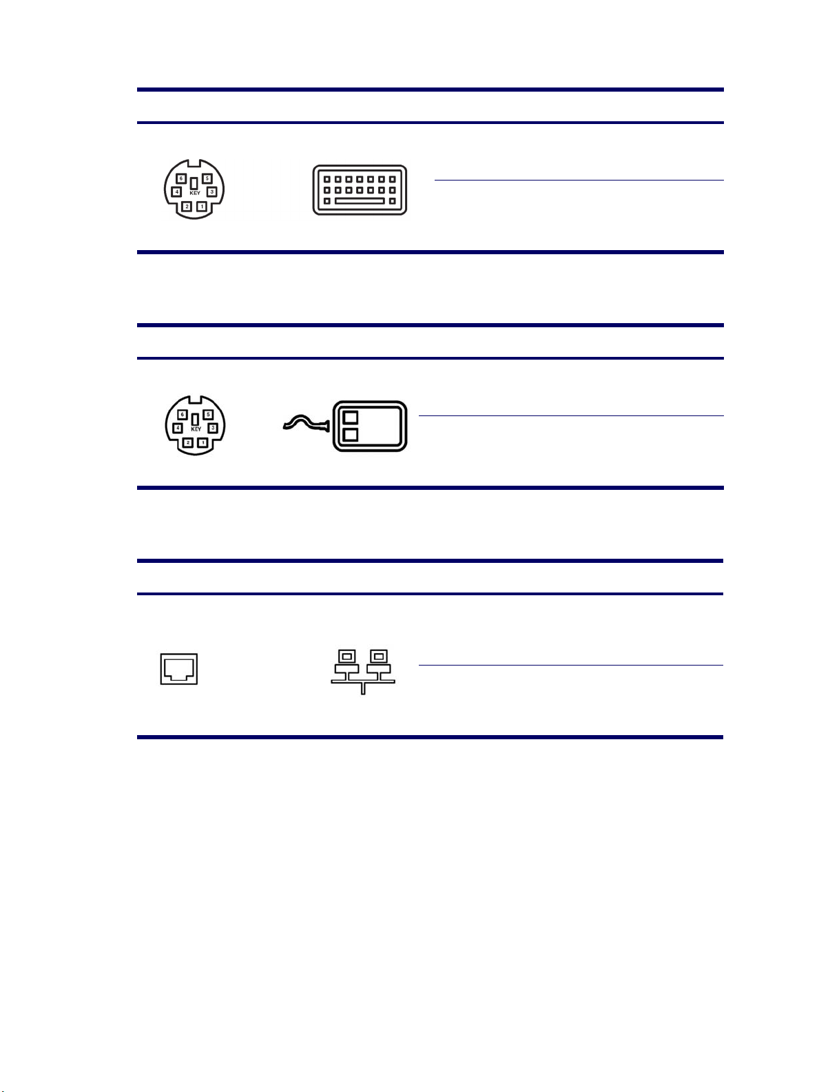
Enhanced Keyboard
Connector and Icon Pin Signal
Mouse
Connector and Icon Pin Signal
Ethernet RJ-45
1
2
3
4
5
6
1
2
3
4
5
6
Data
Unused
Ground
+5 VDC
Clock
Unused
Data
Unused
Ground
+5 VDC
Clock
Unused
Connector and Icon Pin Signal
1
2
3
4
5
6
7
8
(+) Transmit Data
(-) Transmit Data
(+) Receive Data
Unused
Unused
(-) Receive Data
Unused
Unused
164 CONNECTOR PINS
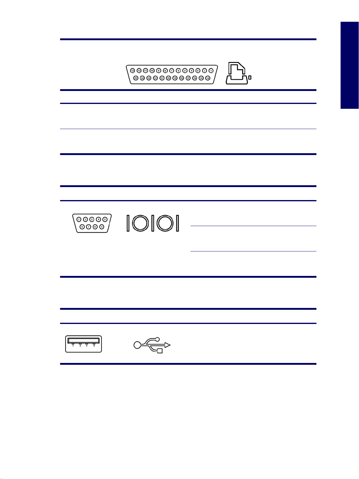
Parallel Interface
Connector and Icon
Pin Signal Pin Signal Pin Signal
Appendix D
1
2
3
4
5
6
Strobe
Data Bit 0
Data Bit 1
Data Bit 2
Data Bit 3
Data Bit 4
Serial Interface
Connector and Icon Pin Signal
7
8
9
10
11
12
Data Bit 5
Data Bit 6
Data Bit 7
Acknowledge
Busy
Paper End
1
2
3
4
5
6
7
8
9
13
14
15
16
17
18–25
Carrier Detect
Receive Data
Transmit Data
Data Terminal Ready
Signal Ground
Data Set Ready
Request to Send
Clear to Send
Ring Indicator
Select
Auto Linefeed
Error
Initialize Printer
Select IN
Signal Ground
USB
Cable connector and Icon Pin Signal
1
2
3
4
+5 VDC
- Data
+ Data
Ground
PARALLEL INTERFACE 165

Microphone
Connector and Icon (1/8") Pin Signal
Headphone
Connector and Icon (1/8") Pin Signal
Line-In Audio
Connector and Icon (1/8") Pin Signal
1 (Tip)
2 (Ring)
3 (Shield)
1 (Tip)
2 (Ring)
3 (Shield)
1 (Tip)
2 (Ring)
3 (Shield)
Audio
Power
Ground
Audio_Left
Audio_Right
Ground
Audio_In_Left
Audio_In_Right
Ground
Line-Out Audio
Connector and Icon (1/8") Pin Signal
166 CONNECTOR PINS
1 (Tip)
2 (Ring)
3 (Shield)
Audio_Out_Left
Audio_Out_Right
Ground

Ultra SCSI
Connector and Icon
SATA
Pin Signal Pin Signal Pin Signal Pin Signal
1–11
12
13
14
15–25
26
27
28
Connector
Pin Usage Pin Usage Pin Signal
Ground
Reserved
Open
Reserved
Ground
DB0
DB1
DB2
29
30
31
32
33
34
35
36
DB3
DB4
DB5
DB6
DB7
DBP
Ground
Ground
37
38
39
40
41
42
43
44
Reserved
TERMPWR
Reserved
Ground
ATN #
Ground
BSY #
ACK #
45
46
47
48
49
50
RST #
MSG #
SEL #
C/D
REQ #
Input/Output
Appendix D
Data Cable Power Cable Power Cable
S-1 Ground P-1 3.3 V power P-8 5V power
S-2* A+ P-2 3.3 V power P-9 5V power
S-3* A- P-3 3.3 V power P-10 Ground
S-4 Ground P-4 Ground P-11 Reserved
S-5** B- P-5 Ground P-12 Ground
S-6** B+ P-6 Ground P-13 12V power
S-7 Ground P-7 5V power P-14 12V power
*S-2 and S-3 differential signal pair
**S-5 and S-6 differential signal pair
P-15 12V power
ULTRA SCSI 167

Monitor
Connector and Icon
Pin Signal Pin Signal Pin Signal
1
2
3
4
5
Red Analog
Green Analog
Blue Analog
Monitor ID
Ground
6
7
8
9
10
Ground
Ground
Ground
+5 V DC
Ground
NOTE Monitor connectors might vary depending on your configuration.
ATA/ATAPI (IDE) Standard Drive Cable
Connector
Pin Signal Pin Signal Pin Signal
11
12
13
14
15
Monitor ID
DDC Serial Data
Horizontal Sync
Vertical Sync
DDC Serial Clock
1
2
3
4
5
6
7
8
9
10
11
12
13
14
168 CONNECTOR PINS
Reset
Ground
DD7
DD8
DD6
DD9
DD5
DD10
DD4
DD11
DD3
DD12
DD2
DD13
15
16
17
18
19
20
21
22
23
24
25
26
27
28
DD1
DD14
DD0
DD15
Ground
(Key)
DMARQ
Ground
DIOW
Ground
DIOR
Ground
IORDY
CSEL
29
30
31
32
33
34
35
36
37
38
39
40
DMAK
Ground
INTRQ
IOCS16
DA1
PDIAG (cable detect)
DA0
DA2
CS1FX
CS3FX
DASP
Ground

24-Pin Power
Connector
Pin Signal Pin Signal Pin Signal Pin Signal
+3.3 V
1
+3.3 V
2
GND
3
+5 V
4
GND
5
+5 V
6
7
8
9
10
11
12
4-Pin Power (for CPU)
24
23
22
21
20
19
18
17
16
15
14
13a
13b
GND
POK
+5 Vaux
+12 V
+12 V
+3.3 V
13
14
15
16
17
18
12
11
10
9
8
7
6
5
4
3
2
1
+3.3 V
-12 V
GND
PSON
GND
GND
19
20
21
22
23
24
Appendix D
GND
NC
+5 V
+5 V
+5 V
GND
Connector and Icon Pin Signal
6-Pin PCI Express
Connector and Icon Pin Signal
1
2
3
4
1
6
5
4
3
2
1
2
3
4
5
6
GND
GND
+12 V
-12 V
+12 V
+12 V
+12 v
GND
GND
GND
24-PIN POWER 169

DVI-I Signals
Connector and Icon Pin Signal
1
2
3
4
5
6
7
8
9
10
11
12
13
14
15
16
17
18
19
20
21
22
23
24
C1
C2
C3
C4
C5
TMDS Data2 TMDS Data2 +
TMDS Data2/4 shield
TMDS Data4 TMDS Data4 +
DCC Clock (SCL)
DCC Bi-directional Data (SDA)
Analog Vertical Sync
TMDS Data1 TMDS Data1 +
TMDS Data1/3 shield
TMDS Data3 TMDS Data3 +
+5V DC Power
Ground Return: +5V, Hsync, Vsync
Hot Plug Detect
TMDS Data0 TMDS Data0 +
TMDS Data0/5 shield
TMDS Data5 TMDS Data5 +
TMDS Clock shield
TMDS Clock +
TMDS Clock Analog Red
Analog Green
Analog Blue
Analog Horizontal Sync
Analog Ground Return: analog Red, Green, Blue
170 CONNECTOR PINS
 Loading...