

Page 1

Quick Setup Guide
Virtual TapeServer for NonStop Servers
Model: VT5900-H, VT5900-K, and VT5900-L, Release: 6.04.03
Part number: 577733-004
Virtual TapeServer (VTS) is a fully integrated virtual tape, hardware, and software solution.
VTS allows host systems to read from and write to a local or SAN-attached file system. For every
host connection to VTS, the host system “sees” a tape drive; the virtual tape drive emulates the
type of tape drive specified during the initial installation and setup process. Data can be
manually migrated to physical tape for archival storage or disaster recovery, if long-term backup
copies are required. The integrated support for backup management application software
enables VTS to write data to physical tape drives and libraries.
This Quick Setup Guide describes how to deploy the VTS hardware and configure VTS on the
network, as follows:
1. Prepare for installation
2. Unpack and identify the hardware
3. Mount the VTS hardware in a rack
4. Cable the VTS server
5. Power on the hardware
6. Configure network settings
7. Configure and label ports
8. Configure storage space and path failover, if necessary
Then, to complete the installation of VTS, you must log in to the web interface as described in
Access the web interface and configure VTS as described in the Virtual TapeServer Installation
Guide. Get help on page 20 describes how to access the product documentation and specifications
and contact Support.
1 Prepare for installation
To ensure that you are ready for deployment, complete the following tasks.
Choose a location
VTS can be mounted in a 19-inch rack near the host server. Allow the following unit spacing:
• VTS server — Allow 2U for the VTS server
• SCSI converter — Allow 1U for the SCSI converter, if necessary
• External storage — Allow 2U each for the VT5917 and VT5918, if purchased
© Copyright 2009 Hewlett-Packard Development Company, L.P.
Page 2

When considering the installation location, note the following guidelines:
• Place the server and its components near 110 or 220/240 volt power outlets. VTS uses
redundant power supplies, so consider independent power sources for high-availability
operation. Additional power outlets might be required for external tape drives or RAID
storage devices.
• Place the VTS server near the host server, within the limits of the cable specifications.
• Identify ports on the host server(s) to which you can connect VTS.
• Make sure the location is a clean, dust-free area that is well ventilated.
• Avoid areas where heat, electrical noise, and electromagnetic fields are generated.
Obtain tools and supplies for installation
You may need the following items to complete the installation instructions:
• #2 Phillips screwdriver
• Level
• Pliers
• Tape measure
• Terminal, keyboard, and mouse, or a computer running a terminal emulation program
•Cables:
Model # Type Description
VT5900-H Up to 4 SCSI (HVD) To connect from the SCSI converter to the host
server or external storage device.
To connect to the SCSI converter, the cable
must have a male MD68 connector. SCSI cable
length is limited to 25 meters (82 feet). Note
that four 2-meter VHDCI-to-MD68 HVD cables
are provided with the SCSI converter.
Up to 4 Fibre optic To connect to one or more host servers, to
connect to one or more external tape drives or
libraries, and to connect to an external disk
array.
It is recommended that you acquire M8900
MMF cables, and a male LC connector is
required to attach to the VTS server.
Up to 3 CAT-5 Ethernet To connect VTS to the network and for HP
Integrated Lights_out (iLO) support.
1 VGA To connect the terminal or computer to VTS.
2 | Virtual TapeServer Quick Setup Guide
Page 3

Model # Type Description
VT5900-K Up to 4 Fibre optic To connect to the host server, and to connect to
an external drive or library. If a second
(optional) Fibre Channel card is installed, you
can connect to up to two host servers and up to
two external drives or libraries.
It is recommended that you acquire M8900
MMF cables, and a male LC connector is
required to attach to the VTS server.
Up to 2 CAT-5 Ethernet To connect VTS to the network.
1 VGA To connect the terminal or computer to VTS.
VT5900-L Up to 10Fibre optic By default, you can connect to up to six host
servers or external drives or libraries. Up to two
additional Fibre Channel cards may be
installed, allowing for up to four more
connections.
It is recommended that you acquire M8900
MMF cables, and a male LC connector is
required to attach to the VTS server.
Up to 5 CAT-5 Ethernet To connect VTS to the network for LAN/WAN
connectivity and for HP Integrated Lights-Out
(iLO) support.
1 VGA To connect the terminal or computer to VTS.
For the most reliable service, use cables of the highest quality and shortest possible length
based on the location of the equipment in the data center. The following is a list of HP cables
and their part numbers, which are provided by HP for VTS installations. (These cables are
provided if listed in the CPSA description for the PID.)
• S-series SCSI cable, 3 m, part number 518-010W
• S-series SCSI cable, 7.6 m, part number 518-025W
• S-series SCSI cable, 15.2 m, part number 518-050W
• S-series SCSI cable, 22.9 m, part number 518-075W
• LC-LC, Multimode Fibre cable, 2 m, part number M8900-02
• LC-LC, Multimode Fibre cable, 5 m, part number M8900-05
• LC-LC, Multimode Fibre cable, 15 m, part number M8900-15
• LC-LC, Multimode Fibre cable, 40 m, part number M8900-40
• LC-LC, Multimode Fibre cable, 80 m, part number M8900-80
Virtual TapeServer Quick Setup Guide | 3
Page 4
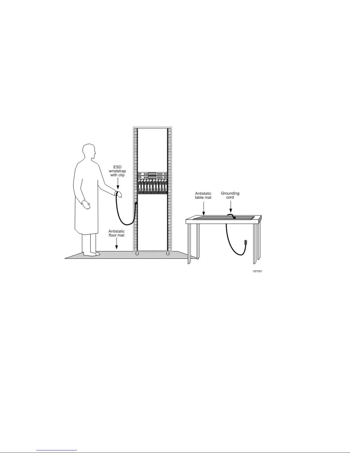
Review standard operating practices
Standard operating practices include
• Obtaining an ESD protection kit and following the directions that come with the kit.
• Ensuring that your ESD protection kit contains an antistatic table mat and that your ESD
wrist strap has a built-in series resistor.
• Removing all metal accessories before working with the equipment.
• Restraining any dangling items that can get caught in equipment.
• Working in an ESD-protected environment:
Gather network information
After you mount and cable the hardware, you must configure the following network settings if
you do not plan to use DHCP (DHCP is not supported with GFS):
• Fully qualified domain name
• IP address
• Subnet mask
• Default router (gateway)
• DNS or DHCP addresses with VTS name entered
A second set of IP settings may be required if configuring Instant DR or AutoCopy. It is
recommended that you segregate Instant DR and AutoCopy traffic from network and EMS traffic
to ensure adequate response times.
It is also recommended that you determine the time zone in which the VTS server will reside.
4 | Virtual TapeServer Quick Setup Guide
Page 5

2Unpack and identify the hardware
Before mounting and cabling VTS, you must unpack the hardware and verify the box contents.
Unpack all hardware
A. Unpack all hardware and retain packing materials.
B. Inspect the hardware and the contents of the box(es). If damage is apparent, contact the
carrier and your vendor.
C. Place hardware on a flat, stable work surface. Always lift the enclosures by the sides.
Because the hardware is heavy, it is recommended that you use an assistant when lifting it.
Confirm that you received the following components, in addition to this guide and the hardware:
• VT5900-H
• Power cords
• HP ProLiant Essentials Foundation Pack CDs
• HP ProLiant DL385 G5 Documentation CD and posters
• HP Virtual TapeServer Base Release 6.04.03 DVD
• Labels for bus numbers
•Rail kit
• VT5900-K
• Power cords
• HP ProLiant DL185 G5 Server Support and Documentation CD
• HP ProLiant DL185 Generation 5 Server Installation Sheet
• HP Virtual TapeServer Base Release 6.04.03 DVD
• External DVD/CD-ROM drive and USB cable
• Labels for bus numbers
•Rail kit
• VT5900-L
• Power cords
• Power Cord Strain Relief Kit (clips and documentation)
• HP Insight Foundation Suite for ProLiant CDs
• HP ProLiant Firmware Maintenance CD
• HP Server Adapter Quick Installation Sheet
• HP ProLiant Server Setup Poster (includes DL380 G6 documentation CD)
• Rail kit (includes rail installation instructions)
• HP Virtual TapeServer Base Release 6.04.03 DVD
• External DVD/CD-ROM drive and USB cable
• Labels for bus numbers
Virtual TapeServer Quick Setup Guide | 5
Page 6

• SCSI converter (shipped with the VT5900-H)
• Power cord
•Rail kit
•SCSI cables
• Virtual TapeServer SCSI Interface Connection Module Sliding Rail Kit Installation guide
• VT5917 (may have been shipped with the VT5900-H and VT5900-L)
• Power cords
• Serial cable
•Rail kit
• VT5918 (may have been shipped with the VT5900-H and VT5900-L)
• HP StorageWorks Modular Smart Array 30 Installation Kit CD
• Power cords
• SAS cables
•Rail kit
Review the VTS server configuration
Here is an overview of the VTS hardware that may have been purchased:
VT5900-H VT5900-K VT5900-L
Server DL385 G5 DL185 G5 DL380 G6
Fibre
Channel
and SCSI
Cards
• Two SCSI cards
(four ports),
or one SCSI card (two
ports) and one FC
card (two 2Gb ports)
One FC card
(two 4Gb ports),
or two FC cards
(four 4Gb ports)
*
• Three FC cards
(six 4Gb ports),
or up to five FC cards
‡
(ten 4Gb ports)
• One FC card
(two 4Gb ports)
Additional
Internal
Eight 146GB internal
disks (VT5904-E)
Six 1TB internal disks
(VT5900-6TB)
Not supported
Storage
External
Disk
Storage
Up to four MSA2000s
(one VT5917 and up to
three VT5918s); each
Not supported Up to one MSA2000
(VT5917 or VT5918),
which provides 12TB
MSA2000 provides
†
12TB
‡
†
6 | Virtual TapeServer Quick Setup Guide
Page 7

VT5900-H VT5900-K VT5900-L
Host
Server
4 2 Up to 10 (if optional FC
cards are installed)
Support
Virtual
Tape Drive
Support
Up to four SCSI VTDs
(one per port),
or up to two SCSI VTDs
and eight FC VTDs (four
Two FC VTDs are
provided; up to six more
can be purchased for a
total of eight FC VTDs
Four FC VTDs are
provided; up to 28 more
can be purchased for a
total of 32 FC VTDs
per port), if an FC card
replaces a SCSI card
* A dual-port 2Gb FC card (VT5900-FCU) may have been purchased to replace one of the SCSI cards in slot 4 or 5
† This is the disk capacity specified by the manufacturer; after RAID 5 formatting, approximately 9.5TB is available
‡ A dual-port 4Gb FC card (VT5900-FC4) may have been purchased and added to the VT5900-K; up to two 4Gb FC cards
(VT5900-FC4) may be added to the VT5900-L
3 Mount the VTS hardware in a rack
To mount the VTS hardware, refer to the following:
• VT5900-H (DL385 G5)
Refer to the HP ProLiant DL385 G5 Documentation poster, which was shipped with the VTS
server.
• VT5900-K (DL185 G5)
Download the HP Rack Rail Kit installation instructions (c01362353.pdf), first edition (Feb
2008).
• VT5900-L (DL380 G6)
Refer to the rail installation instructions provided with the rail kit (part number 506472-001,
November 2008).
• SCSI converter
Refer to the Virtual TapeServer SCSI Interface Connection Module Sliding Rail Kit
Installation guide, which was shipped with VTS.
• MSA2000
Download the HP StorageWorks 2000 Modular Smart Array racking instructions
(c01505852.pdf), first edition (May 2008).
Contact the HP Global Mission Critical Solution Center (GMCSC) if you encounter problems or
need assistance.
Virtual TapeServer Quick Setup Guide | 7
Page 8
4 Cable the VTS server
You must cable the VTS server to the host server, then cable to any external storage devices.
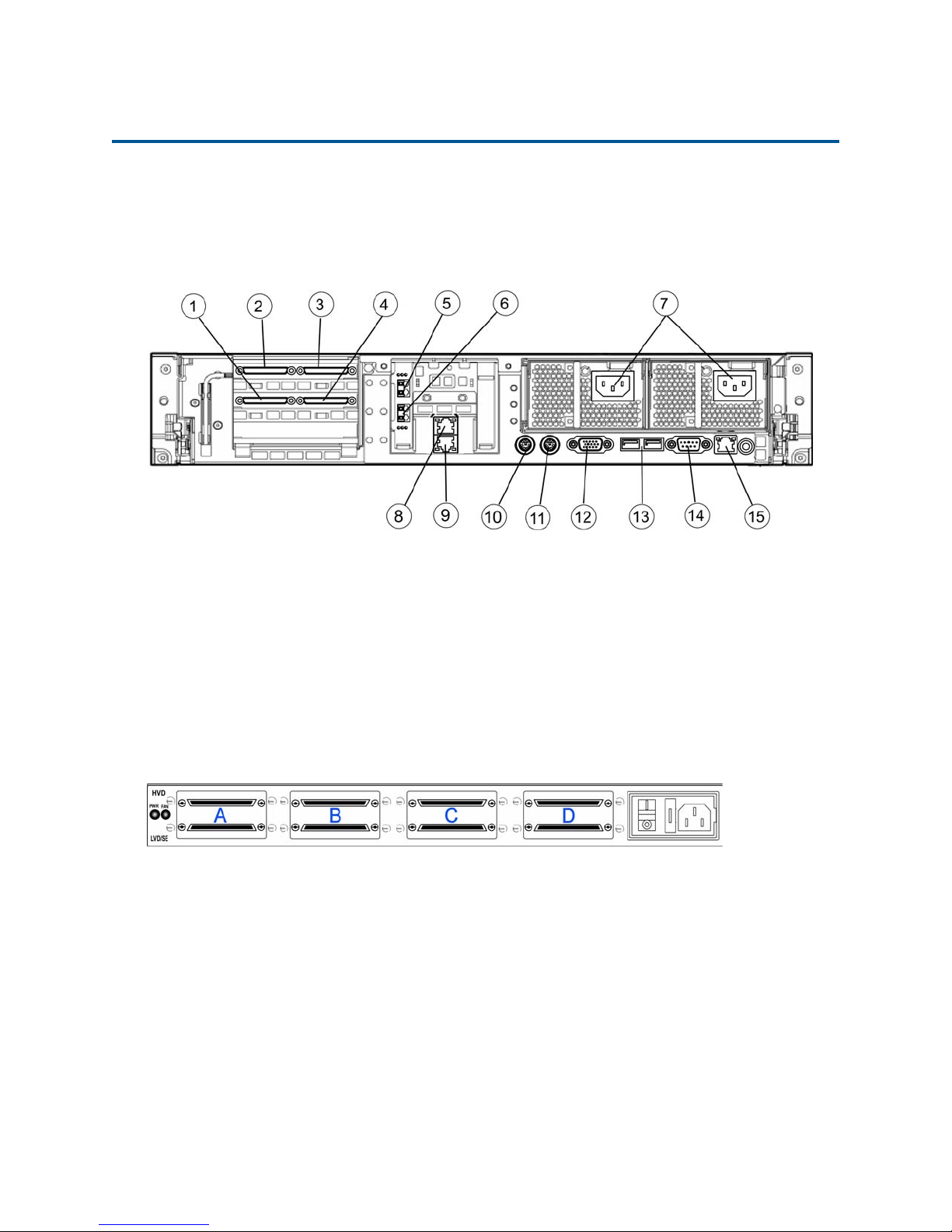
Connect the VT5900-H
Here is an illustration of the back of the VT5900-H (base model):
1. SCSI port (slot 4, port A)
2. SCSI port (slot 5, port A)
3. SCSI port (slot 5, port B)
4. SCSI port (slot 4, port B)
5. 4Gb FC port (slot 2, port A)
The SCSI card in slot 4 may be replaced by a dual-port 2Gb Fibre Channel card (VT5900-FCU).
If the host server requires an HVD SCSI connection, such as the NonStop S-series, you must
connect the VTS server to the SCSI converter, and then connect the SCSI converter to the host
server. Here is an illustration of the HVD and LVD ports on the back of the SCSI converter:
As a best practice, use all 4Gb ports first and connect the external disk array or external tape
device to a 4Gb port. Then, if necessary, connect external storage to the 2Gb ports, which may
provide half the performance as the 4Gb ports.
6. 4Gb FC port (slot 2, port B)
7. Power plugs
8. Ethernet port 2
9. Ethernet port 1
10. PS/2 port
11. PS/2 port
12. VGA port
13. USB ports
14. Serial port
15. iLO port
8 | Virtual TapeServer Quick Setup Guide
Page 9

To connect to host servers through the SCSI converter
Cable the host server to the SCSI converter and cable the SCSI converter to the VTS server:
A. Connect one end of an LVD cable to an LVD bus (port) on the SCSI converter. If cabling to
multiple host servers, the recommended cable connection order is as follows:
HVD Bus A HVD Bus B HVD Bus C HVD Bus D
To NonStop server To NonStop server To NonStop server To NonStop server
LVD Bus A LVD Bus B LVD Bus C LVD Bus D
To VTS slot 4A To VTS slot 4B To VTS slot 5A To VTS slot 5B
It is recommended that you attach to HVD bus D then to HVD bus C and then to HVD buses
A and B if necessary. Also, note that you do not have to use all of the SCSI buses (or
converter ports) for VTDs. You can use the ports as initiators for legacy SCSI tape drives.
B. Connect the other end of the LVD cable to the appropriate SCSI port on the VTS server.
C. Connect one end of an HVD cable to the appropriate HVD bus on the SCSI converter.
D. Connect the other end of the HVD cable to the host server.
E. If you are cabling multiple host servers to VTS, repeat steps A-D.
F. Note the port number used on the VTS server. Later, you will have to set this port to target
mode using the VTS web interface.
To connect to an external Fibre Channel disk array or tape device
A. Connect one end of a Fibre optic cable to the Fibre Channel (FC) port on the VTS server.
B. Connect the other end of the cable to the external disk array or tape drive or library.
You may want to connect a second cable, to provide redundancy. You can connected to a separate
SAN switch or RAID controllers on the server.
To connect to external SCSI tape devices
If the drive or library requires an HVD SCSI connection, follow the steps in To connect to host
servers through the SCSI converter on page 9 to cable the drive or library to the SCSI converter.
Then, follow these steps to cable the SCSI converter to the VTS server.
A. For a SCSI connection, connect one end of an LVD cable to a SCSI port on the VTS server.
For a Fibre Channel connection, connect one end of a Fibre optic cable to a Fibre Channel
(FC) port on the VTS server.
B. Connect the other end of the cable to the external drive or library.
C. Repeat steps A-B for additional drives or libraries.
D. Note the port number(s) used on the VTS server. Later, you will have to set the port(s) to
physical mode using the VTS web interface.
To connect to the network
Connect one end of an Ethernet cable to Ethernet port 1. (Port 1 corresponds to Eth0 in Linux.)
Connect the other end of the cable to the LAN or WAN switch.
If Instant DR or AutoCopy is licensed, you may also want to connect to Ethernet port 2. (Port 2
corresponds to Eth1.) Performance on port 1 may be affected if you do not dedicate a port to
Instant DR or AutoCopy.
Virtual TapeServer Quick Setup Guide | 9
Page 10

To connect to power
A. Connect both power cords to the VTS server.
B. Plug each power cord into a grounded electrical outlet. It is recommended that the cords be
routed to separate power sources for redundancy.
To connect to monitor, keyboard, and mouse
A. Connect one end of a VGA cable into the VGA port on the VTS server.
B. Connect the other end of the cable into the monitor or computer with terminal emulation.
C. If using a keyboard, connect it to a PS/2 or USB port on the VTS server.
D. If using a mouse, connect it to a PS/2 or USB port on the VTS server.
To connect the iLO port to the network
A. Connect one end of an Ethernet cable to the iLO port.
B. Connect the other end of the cable to the LAN or WAN switch.
Connect the VT5900-K
Here is an illustration of the back of the VT5900-K:
1. Power plugs
2. PS/2 port
3. PS/2 port
4. Serial port
The second 4Gb FC card (VT5900-FC4) shown in slot 2 is optional and may not be installed.
To connect to the host server
A. Connect one end of a Fibre optic cable to a Fibre Channel (FC) port on the VTS server.
B. Connect the other end of the cable to the host server.
C. Note the port number used on the VTS server. Later, you will have to set this port to target
mode using the VTS web interface.
10 | Virtual TapeServer Quick Setup Guide
5. FC port (slot 3, port A)
6. FC port (slot 3, port B)
7. Ethernet ports
8. USB ports
9. Mgmt port
10. VGA port
11. FC port (slot 2, port A)
12. FC port (slot 2, port B)
Page 11

To connect to an external tape device
A. Connect one end of a Fibre optic cable to a Fibre Channel (FC) port on the VTS server.
B. Connect the other end of the cable to the external drive or library.
C. Note the port number used on the VTS server. Later, you will have to set the port to physical
mode using the VTS web interface.
To connect to the network
Connect one end of an Ethernet cable to port 1, which is the Ethernet port on the bottom. (Port 1
corresponds to Eth0 in Linux.) Connect the other end of the cable to the LAN or WAN switch.
If Instant DR or AutoCopy is licensed, you may also want to connect to port 2, which is the top
Ethernet port. (Port 2 corresponds to Eth1.) Performance on port 1 may be affected if you do not
dedicate a port to Instant DR or AutoCopy.
To connect to power
A. Connect both power cords to the VTS server.
B. Plug each power cord into a grounded electrical outlet. It is recommended that the cords be
routed to separate power sources for redundancy.
To connect to monitor, keyboard, mouse, and DVD/CD-ROM drive
A. Connect one end of a VGA cable into the 15-pin VGA port on the VTS server.
B. Connect the other end of the cable into the monitor or computer with terminal emulation.
C. If using a keyboard, connect it to a PS/2 or USB port on the VTS server.
D. If using a mouse, connect it to a PS/2 or USB port on the VTS server.
E. Connect one end of the USB cable to the DVD/CD-ROM drive.
F. Connect the other end of the cable to one of the USB ports on the back of the VTS server.
To connect to the management port for Lights-Out 100 support
A. Connect one end of an Ethernet cable to the Mgmt port.
B. Connect the other end of the cable to the LAN or WAN switch.
Virtual TapeServer Quick Setup Guide | 11
Page 12

Connect the VT5900-L
Here is an illustration of the back of the VT5900-L (base model):
1. 4Gb FC ports (slot 2)
2. 4Gb FC ports (slot 3)
3. Power plugs
4. 4Gb FC ports (slot 6)
5. Ethernet ports 4 and 3
6. iLO port
7. Serial port
8. PS/2 ports
9. Ethernet ports 2 and 1
10. VGA port
11. USB ports
An FC card (VT5900-FC4) may be installed in slot 5 (above slot 6). A FC card (VT5900-FC4) may
also be installed in slot 1 (above the fan and power plug on the left), replacing the P800 card that
is installed in the base model.
To connect to host servers using Fibre Channel
A. Connect one end of a Fibre optic cable to a Fibre Channel (FC) port on the VTS server.
B. Connect the other end of the cable to the host server.
C. If you are cabling multiple host servers to VTS, repeat steps A-B for each host server.
D. Note the port number used on the VTS server. Later, you will have to set this port to target
mode using the VTS web interface.
To connect to an external Fibre Channel disk array or external tape devices
A. Connect one end of a Fibre optic cable to the Fibre Channel (FC) port on the VTS server.
B. Connect the other end of the cable to the external disk array or tape drive or library.
C. If you are cabling to multiple tape devices, repeat steps A-B.
You may want to connect a second cable, to provide redundancy. When using the VT5917, for
example, active/active failover can be configured.
To connect to the network
Connect one end of an Ethernet cable to Ethernet port 1, which is the right-most port. (Port 1
corresponds to Eth0 in Linux.) Connect the other end of the cable to the LAN or WAN switch.
If Instant DR or AutoCopy is licensed, you may also want to connect to Ethernet port 2. (Port 2
corresponds to Eth1.) Performance on port 1 may be affected if you do not dedicate a port to
Instant DR or AutoCopy.
12 | Virtual TapeServer Quick Setup Guide
Page 13

To connect to power
A. Connect both power cords to the VTS server.
B. Plug each power cord into a grounded electrical outlet. It is recommended that the cords be
routed to separate power sources for redundancy.
To connect to monitor, keyboard, and mouse
A. Connect one end of a VGA cable into the 15-pin VGA port on the VTS server.
B. Connect the other end of the cable into the monitor or computer with terminal emulation.
C. If using a keyboard, connect it to a PS/2 or USB port on the VTS server.
D. If using a mouse, connect it to a PS/2 or USB port on the VTS server.
To connect the iLO port to the network
A. Connect one end of an Ethernet cable to the iLO port.
B. Connect the other end of the cable to the LAN or WAN switch.
5 Power on the hardware
Perform these steps in order to power all VTS hardware:
A. Press the power button located on the front panel of the VTS server. The power button on the
front panel changes from yellow to green, and the server module self-boots.
Allow the VTS server to completely boot before proceeding. The console will display a login
prompt when it is ready to proceed.
B. Power up the VTS SCSI converter using the power switch on the rear panel, if necessary.
C. Start tape services on the host server. For example, on a NonStop server, use the SCF
START $VTAPE command, where VTAPE is the name of the tape device.
If problems arise, make sure there are no warning lights for any of the disk drives. Contact the
HP Global Mission Critical Solution Center (GMCSC) if you encounter hardware issues.
6 Configure network settings
You must configure the hostname, date, time, and time zone. If you do not want to use Dynamic
Host Configuration Protocol (DHCP), you can also reconfigure VTS to set the IP address (DHCP
is not supported with GFS).
A. Launch a console window and log in as root.
B. When prompted, enter the current password, which is bbill, and then set a new password.
C. Enter startx. The user interface is displayed.
Virtual TapeServer Quick Setup Guide | 13
Page 14

D. Set the IP address and hostname, as follows:
1. From the OS menu, select System Tools→Network Device Control. The Network
Configuration dialog is displayed:
2. Select the network device to modify (eth0 or eth1) and then click Configure. Eth0
corresponds to port 1 on the back of the VTS server, and Eth1 corresponds to port 2. The
Network Configuration dialog is displayed:
14 | Virtual TapeServer Quick Setup Guide
Page 15

3. Double-click the device to modify on the Devices tab. The Ethernet Device dialog is
displayed:
4. Configure the device with static IP settings, or select the option to use DHCP. Then, click
OK to return to the Network Configuration dialog.
5. Click the DNS tab and type the IP address of your DNS server(s) and the domain (DNS
search path).
Note
Do not set the hostname on the DNS tab. You will set this value on the Hosts tab
instead.
6. Click the Hosts table and click New to set the hostname of the VTS server. The Add/Edit
Hosts entry dialog is displayed.
7. Type the fully qualified domain name you want to assign to the VTS server in the
Hostname field, and then specify the IP address and alias (short hostname). Then, click
OK to return to the Network Configuration dialog.
8. Save the settings.
9. Click on the Devices tab, select eth0 (or eth1), and click Activate. When prompted,
click Yes to save the changes. Then, click OK on the next popup dialog.
10. Close the Network Device Control dialog.
Virtual TapeServer Quick Setup Guide | 15
Page 16

E. Set the date, time, and time zone, as follows:
1. From the OS menu, select Administration→Date & Time. The Date/Time Properties
dialog is displayed:
2. Set the date and time on the Date & Time tab.
3. Click the Network Time Protocol tab and enable NTP. Then, add NTP servers.
4. Click the Time Zone tab and set the time zone.
5. Click OK to save the date, time, and time zone settings and close the Date/Time
Properties dialog.
6. Reboot the system.
Note
If you need to configure path failover as described in the next section, you can
reboot after completing those steps.
7. To verify that the fully qualified domain name is set correctly for the VTS server, enter
the following from the command line.
hostname --fqdn
If this is not correct, return to the Network Device Control dialog and correct the
problem.
F. Replace the server certificate. VTS ships with a self-signed certificate that is used to
establish a secure communication channel between your browser and the VTS web
application server, through Secure Sockets Layer (SSL). After the hostname is set on the
server, you must regenerate the certificate with the new hostname. (Later, you can generate
16 | Virtual TapeServer Quick Setup Guide
Page 17
and install a certificate that is signed by a Certificate Authority, as described in the Virtual
TapeServer Installation Guide.)
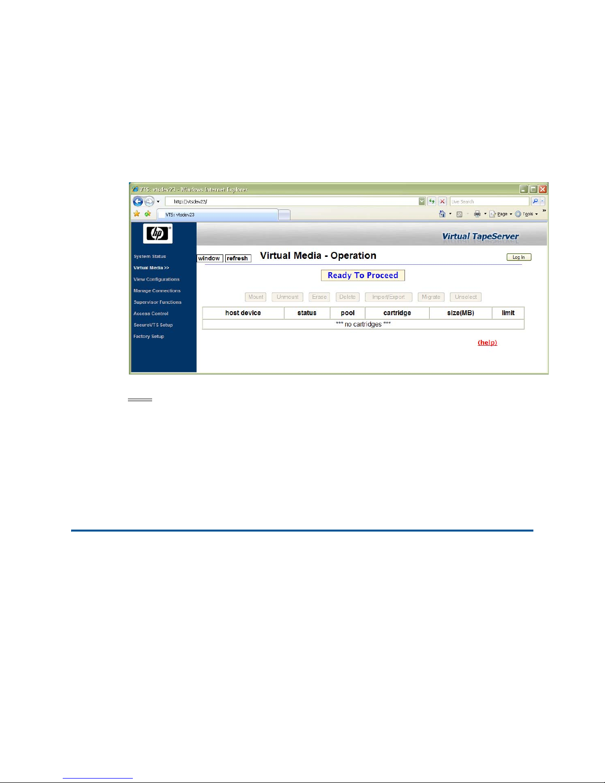
1. From the console window, launch a browser and enter the following URL to access the
web interface:
http://localhost/
The VTS web interface is displayed:
Note
When accessing the web interface from a browser on a remote system, the VTS
web server will redirect the browser to use a secure connection to the fully
qualified domain name of the VTS server. However, the browser is not redirected
if you are accessing the web interface from the local console.
2. Click Log In and log in as a user with Administrative privileges.
3. Click Supervisor Functions on the navigation pane.
4. Click Generate Web Server Certificate.
5. When prompted, click OK to replace the existing web server certificate and restart the
web server.
7 Configure and label ports
After cabling the host server and external devices to the VTS server, you must configure the
ports using the VTS web interface. This will enable VTS to communicate properly with each type
of device (target or initiator).
A. Launch a web browser and enter the IP address or hostname of the VTS server in the
address field. The VTS web interface is displayed.
B. Click Factory Setup on the navigation pane.
C. When prompted to log in, enter factory as the username and zfactoryz as the password.
D. Click Factory Options on the Factory Setup page.
E. Again, enter the login credentials.
Virtual TapeServer Quick Setup Guide | 17
Page 18
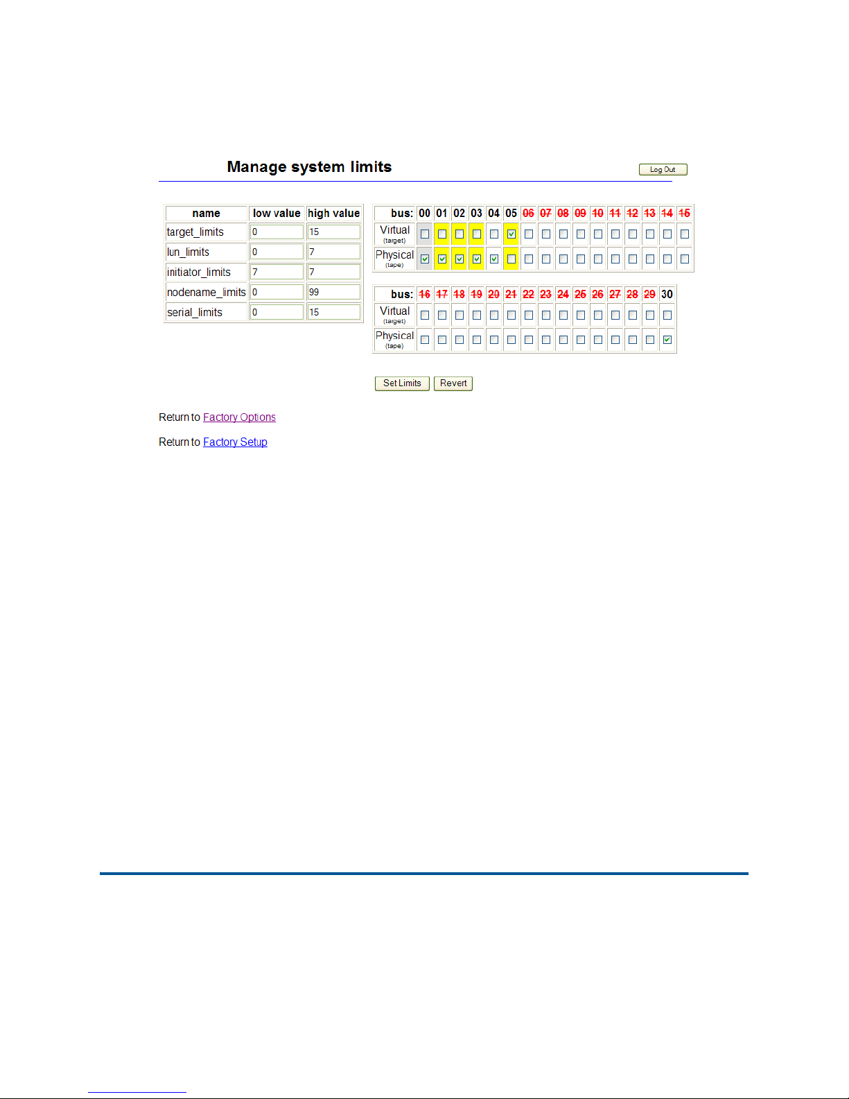
F. Click Manage system limits. The following page is displayed:
G. Configure the port used to attach VTS to the host server. Select the Virtual checkbox for the
bus (port) that is attached to the host server. Be aware of the following:
• Grey boxes indicate ports on the SCSI card(s)
• Yellow boxes indicate ports on the Fibre Channel card(s); hold your cursor over the
checkbox to view the speed of the port
• It is recommended that you set the highest numbered ports to Virtual.
Click OK to acknowledge that the bus may migrate to a new bus number following a reboot,
and the click OK to confirm that you want to set the bus to virtual mode.
H. Configure the port(s) used to attach VTS to the external storage device(s). For each port that
was used, select the Physical checkbox.
I. Click Set Limits. The VTS server automatically reboots.
J. Label the ports on the back of the VTS server. Locate the bus number labels that were
shipped with VTS. For each port that is used, apply a label. The number on the label should
correspond to the bus number on the Manage system limits page.
If problems arise:
• Be sure that you are using a local web browser instead of remote web browser.
• Enter localhost in the address field of the browser instead of the hostname or IP address.
• Make sure there are no bus conflicts with a physical drive on a virtual port or with the
virtual port.
8 Configure storage space and path failover
If deploying external storage for use with VTS, you must define a storage space on the disk array
for use with the Linux operating system. Then, present a logical unit number (LUN) that refers
to this storage space. Note that each LUN should not represent more than 4TB of space.
18 | Virtual TapeServer Quick Setup Guide
Page 19

Path failover is required when more than one physical or logical path exists between VTS and
external disk storage, such as an MSA or HP StorageWorks Enterprise Virtual Array (EVA). (For
the EVA, a path failover connection is required through two ports on the VTS server to two ports
on the EVA.) If a path fails, another path becomes active and handles I/O for the LUNs on the
failed path. Only one path is active at a time for a LUN. You can run the multipath -v2 -ll
command to see a list of known multi-pathed disks.
You can use the Device Mapper Multipath Enablement Kit to configure path failover. The dmmultipath and devicemapper RPMs are installed by default on the VTS server. You must
download the latest version of the Device Mapper Multipath Enablement Kit; the kit contains a
multipath.conf file that can be used with VTS:
http://h20000.www2.hp.com/bizsupport/TechSupport/
SoftwareIndex.jsp?lang=en&cc=us&prodNameId=3559652&prodTypeId=12169&prodSeriesId=3
559651&swLang=13&taskId=135&swEnvOID=4004
Then, download the latest version of the Device Mapper Multipath Enablement Kit for HP
StorageWorks Disk Arrays Release Notes document from this URL:
http://h20000.www2.hp.com/bizsupport/TechSupport/
DocumentIndex.jsp?lang=en&cc=us&prodClassId=1&contentType=SupportManual&prodTypeId=18964&prodSeriesId=3559651
Note
Review the “Device Mapper Multipath support matrix” section of these release notes to
ensure that the firmware version of your storage device supports multi-pathing. If
necessary, upgrade your storage device firmware.
Then, install and configure the device mapper tools as described in the following sections of the
release notes:
• “Installing Device Mapper Multipath tools”
• “Configuring Device Mapper Multipath to enable HP arrays”
• “Setting up Device Mapper Multipath daemon”
9 Access the web interface
The VTS web interface enables you to configure and manage VTS. To access the web interface,
launch a web browser and enter the following in the address field:
https://ip_address
where ip_address is the management network interface address.
Or, if the Domain Name System (DNS) is configured on the network, enter the following:
https://hostname
where hostname is that of the VTS server.
When accessing the web interface from a browser on a remote system, the VTS web server will
redirect the browser to use a secure connection to the fully qualified domain name of the VTS
server. If problems arise, access the web interface from the local console; the browser is not
redirected in this case. Accessing the web interface from the local console may help you resolve
problems that may result from the redirection and use of certificates.
Virtual TapeServer Quick Setup Guide | 19
Page 20

Get help
This section lists documents and URLs that you can reference for more information about VTS.
Documentation
• Virtual TapeServer Installation Guide, which describes how to configure VTS.
• Virtual TapeServer Operations and Administration Guide, which describes how to use the
VTS web interface to manage VTS
Specifications
• VT5900-H (DL385 G5)
http://h18004.www1.hp.com/products/quickspecs/13012_na/13012_na.html
• VT5900-K (DL185 G5)
http://h18004.www1.hp.com/products/quickspecs/12864_na/12864_na.html
• VT5900-L (DL380 G6)
http://h18004.www1.hp.com/products/quickspecs/13234_na/13234_na.html
• SCSI Converter
http://www.rancho.com/Products.aspx?ID=2&Model=RTLVD-HVDRxER&CatID=1
http://www.rancho.com/DataSheets/RTLVD-xxxRxE_M.pdf
• MSA2000
http://h18000.www1.hp.com/products/quickspecs/13187_na/13187_na.html
Support
Contact the HP Global Mission Critical Solution Center (GMCSC).
Safety and compliance
Regulatory Compliance Statements
The following regulatory compliance statements apply to the products documented by this guide.
FCC Compliance
This equipment has been tested and found to comply with the limits for a Class A digital device,
pursuant to part 15 of the FCC Rules. These limits are designed to provide reasonable protection
against harmful interference when the equipment is operated in a commercial environment. This
equipment generates, uses, and can radiate radio-frequency energy and, if not installed and used
in accordance with the instruction manual, may cause interference to radio communications.
Operation of this equipment in a residential area is likely to cause harmful interference in which
case the user will be required to correct the interference at his own expense.
Any changes or modifications not expressly approved by Hewlett-Packard Computer Corporation
could void the user’s authority to operate this equipment.
Canadian Compliance
This class A digital apparatus meets all the requirements of the Canadian Interference-Causing
Equipment Regulations.
20 | Virtual TapeServer Quick Setup Guide
Page 21

Cet appareil numérique de la classe A respecte toutes les exigences du Règlement sur le matériel
brouilleur du Canada.
Korea MIC Compliance
Taiwan (BSMI) Compliance
Japan (VCCI) Compliance
This is a Class A product based on the standard or the Voluntary Control Council for
Interference by Information Technology Equipment (VCCI). If this equipment is used in a
domestic environment, radio disturbance may occur, in which case the user may be required to
take corrective actions.
European Union Notice
Products with the CE Marking comply with both the EMC Directive (89/336/EEC) and the Low
Voltage Directive (73/23/EEC) issued by the Commission of the European Community.
Compliance with these directives implies conformity to the following European Norms (the
equivalent international standards are in parenthesis):
• EN55022 (CISPR 22)—Electromagnetic Interference
• EN55024 (IEC61000-4-2, 3, 4, 5, 6, 8, 11)—Electromagnetic Immunity
• EN61000-3-2 (IEC61000-3-2)—Power Line Harmonics
Virtual TapeServer Quick Setup Guide | 21
Page 22

• EN61000-3-3 (IEC61000-3-3)—Power Line Flicker
• EN60950-1 (IEC60950-1)—Product Safety
Laser Compliance
This product may be provided with an optical storage device (that is, CD or DVD drive) and/or
fiber optic transceiver. Each of these devices contains a laser that is classified as a Class 1 Laser
80 Safety and Compliance Product in accordance with US FDA regulations and the IEC 60825-1.
The product does not emit hazardous laser radiation.
WARNING: Use the controls or adjustments or performance of procedures other than
those specified herein or in the laser product’s installation guide may result in hazardous
radiation exposure. To reduce the risk of exposure to hazardous radiation:
• Do not try to open the module enclosure. There are no user-serviceable components
inside.
• Do not operate controls, make adjustments, or perform procedures to the laser device
other than those specified herein.
• Allow only HP Authorized Service technicians to repair the module.
The Center for Devices and Radiological Health (CDRH) of the U.S. Food and Drug
Administration implemented regulations for laser products on August 2, 1976. These regulations
apply to laser products manufactured from August 1, 1976. Compliance is mandatory for
products marketed in the United States.
SAFETY CAUTION
The following icon or caution statements may be placed on equipment to indicate the presence of
potentially hazardous conditions:
DUAL POWER CORDS CAUTION: “THIS UNIT HAS MORE THAN ONE POWER
SUPPLY CORD. DISCONNECT ALL POWER SUPPLY CORDS TO COMPLETELY
REMOVE POWER FROM THIS UNIT.” “ATTENTION: CET APPAREIL COMPORTE
PLUS D'UN CORDON D'ALIMENTATION. DÉBRANCHER TOUS LES CORDONS
D'ALIMENTATION AFIN DE COUPER COMPLÈTEMENT L'ALIMENTATION DE
CET ÉQUIPEMENT”. DIESES GERÄT HAT MEHR ALS EIN NETZKABEL. VOR DER
WARTUNG BITTE ALLE NETZKABEL AUS DER STECKDOSE ZIEHEN.
Any surface or area of the equipment marked with these symbols indicates the presence of
electric shock hazards. The enclosed area contains no operator-serviceable parts.
WARNING: To reduce the risk of injury from electric shock hazards, do not open this
enclosure.
NOT FOR EXTERNAL USE
CAUTION: NOT FOR EXTERNAL USE. ALL RECEPTACLES ARE FOR INTERNAL USE
ONLY.
ATTENTION: NE PAS UTILISER A L’EXTERIEUR DE L’EQUIPEMENT
IMPORTANT: TOUS LES RECIPIENTS SONT DESTINES UNIQUEMENT A UN USAGE
INTERNE.
VORSICHT: ALLE STECKDOSEN DIENEN NUR DEM INTERNEN GEBRAUCH.
HIGH LEAKAGE CURRENT
To reduce the risk of electric shock due to high leakage currents, a reliable grounded (earthed)
connection should be checked before servicing the power distribution unit (PDU).
22 | Virtual TapeServer Quick Setup Guide
Page 23

Observe the following limits when connecting the product to AC power distribution devices: For
PDUs that have attached AC power cords or are directly wired to the building power, the total
combined leakage current should not exceed 5 percent of the rated input current for the device.
“HIGH LEAKAGE CURRENT, EARTH CONNECTION ESSENTIAL BEFORE CONNECTING
SUPPLY”
“HOHER ABLEITSTROM. VOR INBETRIEBNAHME UNBEDINGT
ERDUNGSVERBINDUNG HERSTELLEN”
“COURANT DE FUITE E’LEVE’. RACCORDEMENT A LA TERRE INDISPENSABLE AVANT
LE RACCORDEMENT AU RESEAU”
FUSE REPLACEMENT
CAUTION – For continued protection against risk of fire, replace fuses only with fuses of the
same type and the same rating. Disconnect power before changing fuses.
Important Safety Information
Safety information is located in two places.
HP NonStop NS-Series Servers
Safety information is available from the NTL home page. Select Safety and Compliance >
Important Safety Information. To open the safety information in a language other than English,
select the language. Local HP support can also help direct you to your safety information.
HP NonStop S-Series Servers
Customer Installation and Servicing of Equipment
The following statements pertain to safety issues regarding customer installation and servicing
of equipment described in this manual.
• Keep door closed for normal operation.
• The equipment must be installed near the receptacles for the power cords, and the
receptacles must be easily accessible to the user.
Do not touch the DC power connector on the S7400/S7x000 PMF CRU after you have
unplugged the DC power cable from the CRU. It is possible to incur a severe energy
hazard for as long as fifteen (15) seconds after unplugging the cable. You can make sure
the CRU is safe to remove by testing (by using a volt meter) before touching the pins on
the DC power connector.
Applicability of Procedures, Instructions, and Examples
WARNING! The procedures and instructions and the examples of procedures and
instructions found in this manual apply only to the system enclosures and components
found in Himalaya S-series servers which are described in the Himalaya S-series server
documentation. Do not attempt to use these instructions with any other Tandem NonStop
system equipment. You can determine that your system is a Himalaya S-series server by
reading the label that appears inside each system enclosure on the CRU in slot 50 or 55.
The label includes the product number 1980. Read the label before proceeding with any
procedure or instruction found in this manual.
Virtual TapeServer Quick Setup Guide | 23
Page 24

24 | Virtual TapeServer Quick Setup Guide
 Loading...