

Page 1
User’s Guide
HP Vectra XM
5/xx Series 3
blckfoot.bk : 1bookf.fb4 Page 1 Monday, July 21, 1997 3:38 PM
Page 2
Notice
The information contained in this document is subject to change
without notice.
Hewlett-Packard makes no warranty of any kind with regard to this
material, including, but not limited to, the implied warranties of
merchantability and fitness for a particular purpose. Hewlett-Packard
shall not be liable for errors contained herein or for incidental or
consequential damages in connection with the furnishing, performance,
or use of this material.
Hewlett-Packard assumes no responsibility for the use or reliability of
its software on equipment that is not furnished by Hewlett-Packard.
This document contains proprietary information that is protected by
copyright. All rights are reserved. No part of this document may be
photocopied, reproduced, or translated to another language without the
prior written consent of Hewlett-Packard Company.
Centronics
®
is a registered trademark of Centronics Data Computer
Corporation.
Microsoft
®
and MS-DOS® are U.S. registered trademarks of Microsoft
Corporation. LAN Manager, Microsoft Windows, and Windows 95 are
products of Microsoft Corporation.
OS/2 is a registered trademark of International Business Machines
corporation.
Novell
®
and NetWare® are U.S. registered trademarks of Novell, Inc.
PENTIUM
TM
is a trademark of Intel Corporation.
UNIX
®
is a registered trademark of UNIX System Laboratories Inc. in
the U.S.A. and other countries.
Hewlett-Packard France
Grenoble Personal Computer Division
Technical Marketing
38053 Grenoble Cedex 9
France
1995 Hewlett-Packard Company
blckfoot.bk : legal.fb4 Page ii Monday, July 21, 1997 3:38 PM
Page 3
User’s Guide
blckfoot.bk : title.fb4 Page iii Monday, July 21, 1997 3:38 PM
Page 4
iv Francais
Welcome to Your HP Vectra PC
Congratulations on the purchase of your new Hewlett-Packard
Personal Computer. Your high-performance HP Vectra PC provides:
•
a PentiumTM processor in a Zero Insertion Force (ZIF) socket for
easy processor upgrades
•
an integrated level-two cache of 256 KB for improved performance
•
a main memory of 8 MB, upgradeable to 192 MB
•
an Ultra VGA PCI (Peripheral Component Interconnect) video
controller with 1 MB of video memory (upgradeable to 2 MB)
•
an integrated Enhanced IDE (Integrated Drive Electronics)
controller on the PCI bus supporting Fast IDE and Standard IDE
•
a 32-bit PCI integrated Ethernet LAN controller
•
four mass storage shelves:
❒
three front-access shelves
❒
one internal shelf
•
four free slots for accessory boards:
❒
one 32-bit PCI (Peripheral Component Interconnect) slot
❒
two 16-bit ISA (Industry Standard Architecture) slots
❒
one combination ISA or PCI slot
•
one LAN connector, one parallel port, and two serial ports
•
preloaded HP utilities to ease system configuration tasks
•
BIOS stored in Flash ROM (for easy upgradeability)
•
BIOS support for ISA “Plug and Play”
•
DMI compliant with preloaded DMI demonstration application
•
Designed for WindowsTM 95
•
Energy Star compliant.
blckfoot.bk : title.fb4 Page iv Monday, July 21, 1997 3:38 PM
Page 5
Francais v
Preloaded Software
For your convenience, your HP Vectra PC comes with the following
software:
Software, Utilities,
and Drivers
❒
MS-DOS 6.22
❒
MS-Windows for Workgroups 3.11
❒
HP User Tools
❒
Dashboard
❒
Mouse Control Center
❒
HP Video drivers
❒
HP LAN drivers
❒
Microsoft network client
❒
Novell network client
❒
HP IDE Disk drivers (for 32-bit disk access)
❒
ISA Plug and Play configuration utility (ICU) and driver
❒
Advanced Power Management
❒
Desktop Management Interface.
HP recommends that you create master diskettes for your preloaded
software as soon as possible. Refer to chapter 1 for instructions.
Online Guides
Additionally, your HP Vectra PC has these online guides preloaded in
the HPutils group in the Windows Program Manager:
❒
Discover Your HP Vectra
❒
Network Administrator Guide.
blckfoot.bk : title.fb4 Page v Monday, July 21, 1997 3:38 PM
Page 6
vi Francais
blckfoot.bk : title.fb4 Page vi Monday, July 21, 1997 3:38 PM
Page 7
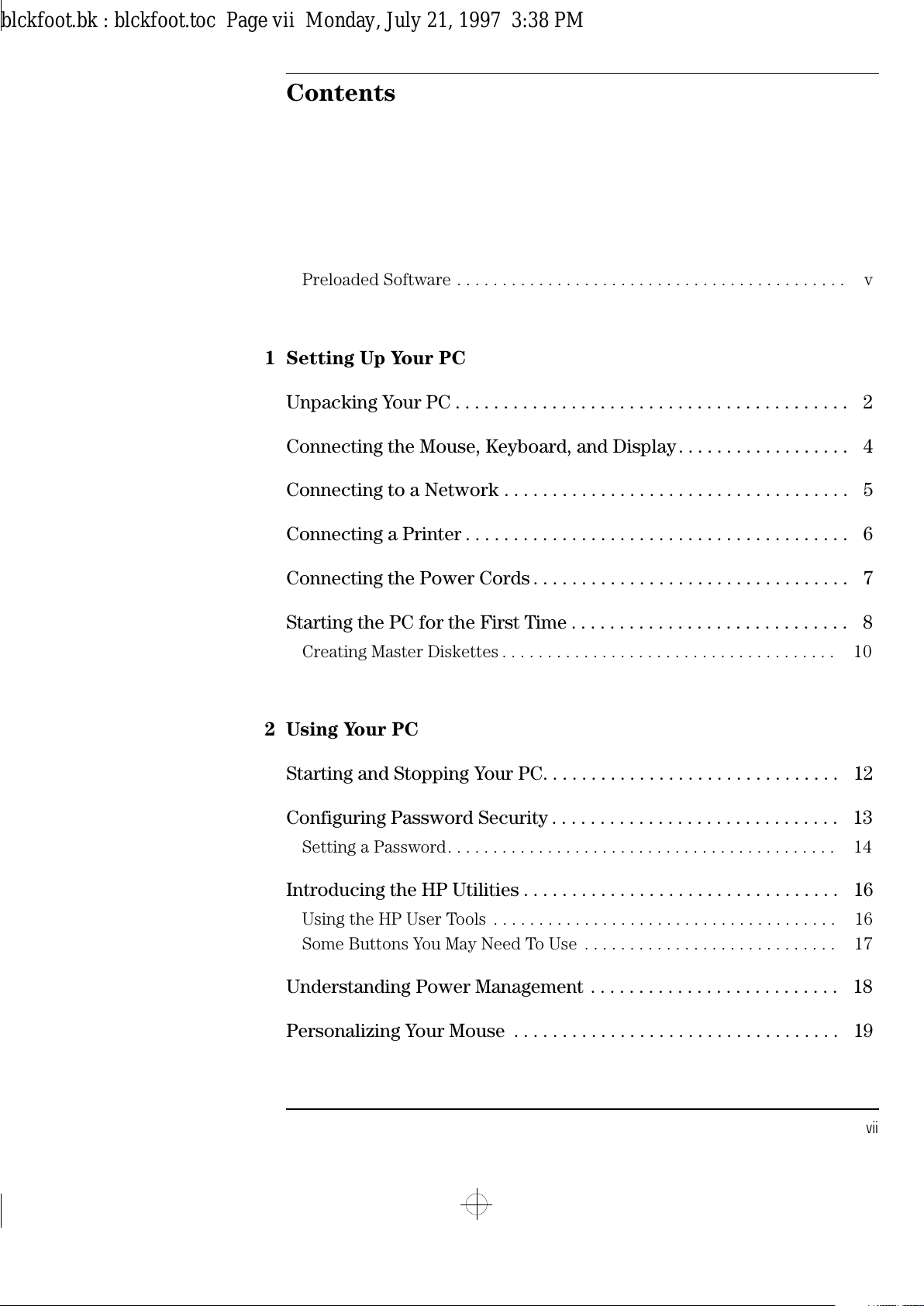
Contents
English vii
Preloaded Software . . . . . . . . . . . . . . . . . . . . . . . . . . . . . . . . . . . . . . . . . . . v
1 Setting Up Your PC
Unpacking Your PC . . . . . . . . . . . . . . . . . . . . . . . . . . . . . . . . . . . . . . . . . 2
Connecting the Mouse, Keyboard, and Display. . . . . . . . . . . . . . . . . . 4
Connecting to a Network . . . . . . . . . . . . . . . . . . . . . . . . . . . . . . . . . . . . 5
Connecting a Printer . . . . . . . . . . . . . . . . . . . . . . . . . . . . . . . . . . . . . . . . 6
Connecting the Power Cords . . . . . . . . . . . . . . . . . . . . . . . . . . . . . . . . . 7
Starting the PC for the First Time . . . . . . . . . . . . . . . . . . . . . . . . . . . . . 8
Creating Master Diskettes . . . . . . . . . . . . . . . . . . . . . . . . . . . . . . . . . . . . . 10
2 Using Your PC
Starting and Stopping Your PC. . . . . . . . . . . . . . . . . . . . . . . . . . . . . . . 12
Configuring Password Security . . . . . . . . . . . . . . . . . . . . . . . . . . . . . . 13
Setting a Password. . . . . . . . . . . . . . . . . . . . . . . . . . . . . . . . . . . . . . . . . . . 14
Introducing the HP Utilities . . . . . . . . . . . . . . . . . . . . . . . . . . . . . . . . . 16
Using the HP User Tools . . . . . . . . . . . . . . . . . . . . . . . . . . . . . . . . . . . . . . 16
Some Buttons You May Need To Use . . . . . . . . . . . . . . . . . . . . . . . . . . . . 17
Understanding Power Management . . . . . . . . . . . . . . . . . . . . . . . . . . 18
Personalizing Your Mouse . . . . . . . . . . . . . . . . . . . . . . . . . . . . . . . . . . 19
blckfoot.bk : blckfoot.toc Page vii Monday, July 21, 1997 3:38 PM
Page 8
viii English
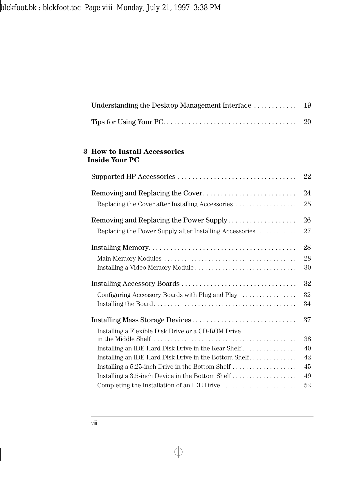
Understanding the Desktop Management Interface . . . . . . . . . . . . 19
Tips for Using Your PC. . . . . . . . . . . . . . . . . . . . . . . . . . . . . . . . . . . . . 20
3 How to Install Accessories
Inside Your PC
Supported HP Accessories . . . . . . . . . . . . . . . . . . . . . . . . . . . . . . . . . 22
Removing and Replacing the Cover. . . . . . . . . . . . . . . . . . . . . . . . . . 24
Replacing the Cover after Installing Accessories . . . . . . . . . . . . . . . . . . 25
Removing and Replacing the Power Supply . . . . . . . . . . . . . . . . . . . 26
Replacing the Power Supply after Installing Accessories . . . . . . . . . . . . 27
Installing Memory. . . . . . . . . . . . . . . . . . . . . . . . . . . . . . . . . . . . . . . . . 28
Main Memory Modules . . . . . . . . . . . . . . . . . . . . . . . . . . . . . . . . . . . . . . . 28
Installing a Video Memory Module . . . . . . . . . . . . . . . . . . . . . . . . . . . . . . 30
Installing Accessory Boards . . . . . . . . . . . . . . . . . . . . . . . . . . . . . . . . 32
Configuring Accessory Boards with Plug and Play . . . . . . . . . . . . . . . . . 32
Installing the Board. . . . . . . . . . . . . . . . . . . . . . . . . . . . . . . . . . . . . . . . . . 34
Installing Mass Storage Devices. . . . . . . . . . . . . . . . . . . . . . . . . . . . . 37
Installing a Flexible Disk Drive or a CD-ROM Drive
in the Middle Shelf . . . . . . . . . . . . . . . . . . . . . . . . . . . . . . . . . . . . . . . . . . 38
Installing an IDE Hard Disk Drive in the Rear Shelf . . . . . . . . . . . . . . . . 40
Installing an IDE Hard Disk Drive in the Bottom Shelf. . . . . . . . . . . . . . 42
Installing a 5.25-inch Drive in the Bottom Shelf . . . . . . . . . . . . . . . . . . . 45
Installing a 3.5-inch Device in the Bottom Shelf . . . . . . . . . . . . . . . . . . . 49
Completing the Installation of an IDE Drive . . . . . . . . . . . . . . . . . . . . . . 52
blckfoot.bk : blckfoot.toc Page viii Monday, July 21, 1997 3:38 PM
Page 9
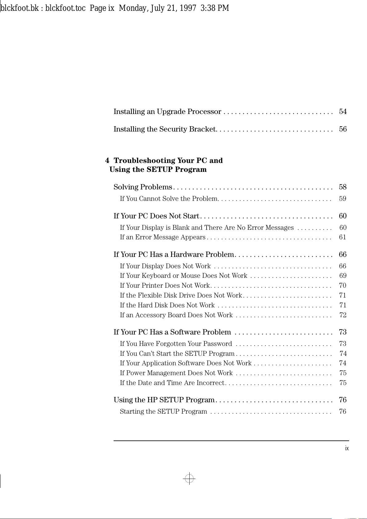
English ix
Installing an Upgrade Processor . . . . . . . . . . . . . . . . . . . . . . . . . . . . . 54
Installing the Security Bracket. . . . . . . . . . . . . . . . . . . . . . . . . . . . . . . 56
4 Troubleshooting Your PC and
Using the SETUP Program
Solving Problems. . . . . . . . . . . . . . . . . . . . . . . . . . . . . . . . . . . . . . . . . . 58
If You Cannot Solve the Problem. . . . . . . . . . . . . . . . . . . . . . . . . . . . . . . . 59
If Your PC Does Not Start. . . . . . . . . . . . . . . . . . . . . . . . . . . . . . . . . . . 60
If Your Display is Blank and There Are No Error Messages . . . . . . . . . . 60
If an Error Message Appears . . . . . . . . . . . . . . . . . . . . . . . . . . . . . . . . . . . 61
If Your PC Has a Hardware Problem. . . . . . . . . . . . . . . . . . . . . . . . . . 66
If Your Display Does Not Work . . . . . . . . . . . . . . . . . . . . . . . . . . . . . . . . . 66
If Your Keyboard or Mouse Does Not Work . . . . . . . . . . . . . . . . . . . . . . . 69
If Your Printer Does Not Work. . . . . . . . . . . . . . . . . . . . . . . . . . . . . . . . . . 70
If the Flexible Disk Drive Does Not Work. . . . . . . . . . . . . . . . . . . . . . . . . 71
If the Hard Disk Does Not Work . . . . . . . . . . . . . . . . . . . . . . . . . . . . . . . . 71
If an Accessory Board Does Not Work . . . . . . . . . . . . . . . . . . . . . . . . . . . 72
If Your PC Has a Software Problem . . . . . . . . . . . . . . . . . . . . . . . . . . 73
If You Have Forgotten Your Password . . . . . . . . . . . . . . . . . . . . . . . . . . . 73
If You Can’t Start the SETUP Program . . . . . . . . . . . . . . . . . . . . . . . . . . . 74
If Your Application Software Does Not Work . . . . . . . . . . . . . . . . . . . . . . 74
If Power Management Does Not Work . . . . . . . . . . . . . . . . . . . . . . . . . . . 75
If the Date and Time Are Incorrect. . . . . . . . . . . . . . . . . . . . . . . . . . . . . . 75
Using the HP SETUP Program. . . . . . . . . . . . . . . . . . . . . . . . . . . . . . . 76
Starting the SETUP Program . . . . . . . . . . . . . . . . . . . . . . . . . . . . . . . . . . 76
blckfoot.bk : blckfoot.toc Page ix Monday, July 21, 1997 3:38 PM
Page 10
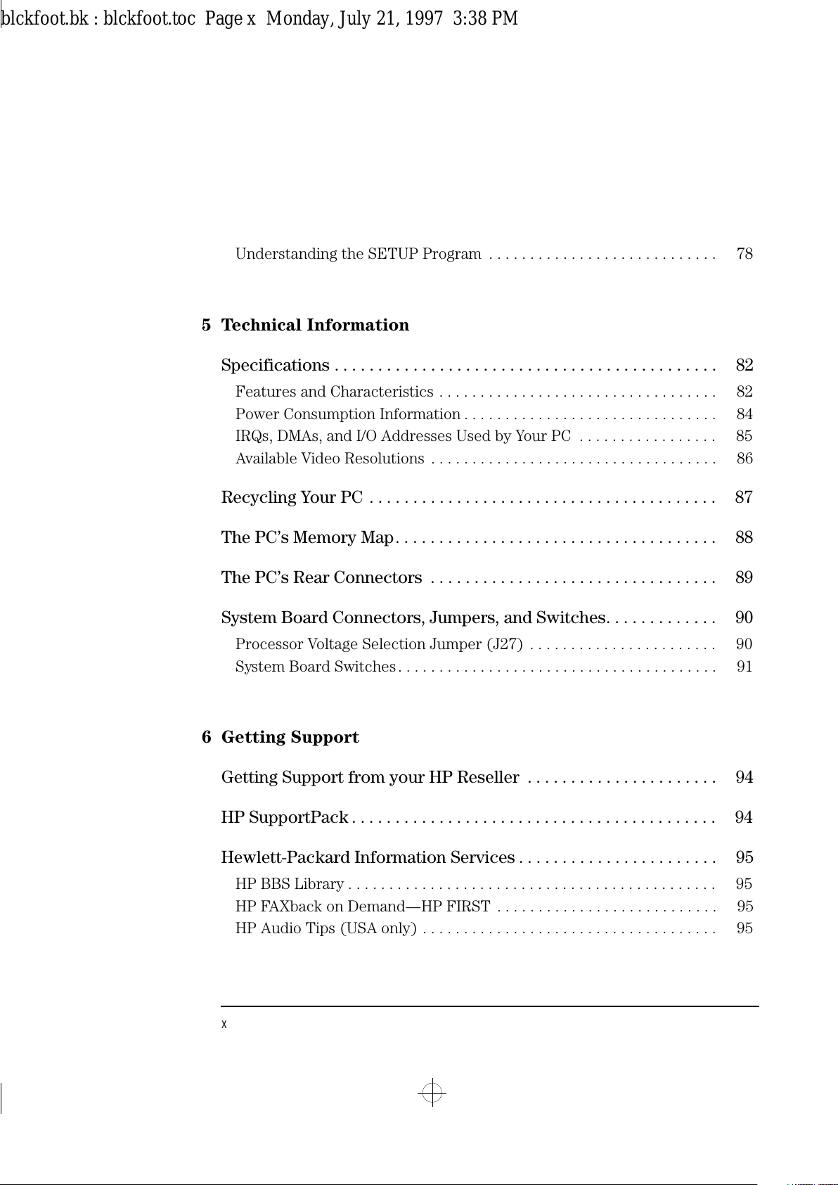
x English
Understanding the SETUP Program . . . . . . . . . . . . . . . . . . . . . . . . . . . . 78
5 Technical Information
Specifications . . . . . . . . . . . . . . . . . . . . . . . . . . . . . . . . . . . . . . . . . . . . 82
Features and Characteristics . . . . . . . . . . . . . . . . . . . . . . . . . . . . . . . . . . 82
Power Consumption Information . . . . . . . . . . . . . . . . . . . . . . . . . . . . . . . 84
IRQs, DMAs, and I/O Addresses Used by Your PC . . . . . . . . . . . . . . . . . 85
Available Video Resolutions . . . . . . . . . . . . . . . . . . . . . . . . . . . . . . . . . . . 86
Recycling Your PC . . . . . . . . . . . . . . . . . . . . . . . . . . . . . . . . . . . . . . . . 87
The PC’s Memory Map. . . . . . . . . . . . . . . . . . . . . . . . . . . . . . . . . . . . . 88
The PC’s Rear Connectors . . . . . . . . . . . . . . . . . . . . . . . . . . . . . . . . . 89
System Board Connectors, Jumpers, and Switches. . . . . . . . . . . . . 90
Processor Voltage Selection Jumper (J27) . . . . . . . . . . . . . . . . . . . . . . . 90
System Board Switches. . . . . . . . . . . . . . . . . . . . . . . . . . . . . . . . . . . . . . . 91
6 Getting Support
Getting Support from your HP Reseller . . . . . . . . . . . . . . . . . . . . . . 94
HP SupportPack . . . . . . . . . . . . . . . . . . . . . . . . . . . . . . . . . . . . . . . . . . 94
Hewlett-Packard Information Services . . . . . . . . . . . . . . . . . . . . . . . 95
HP BBS Library . . . . . . . . . . . . . . . . . . . . . . . . . . . . . . . . . . . . . . . . . . . . . 95
HP FAXback on Demand—HP FIRST . . . . . . . . . . . . . . . . . . . . . . . . . . . 95
HP Audio Tips (USA only) . . . . . . . . . . . . . . . . . . . . . . . . . . . . . . . . . . . . 95
blckfoot.bk : blckfoot.toc Page x Monday, July 21, 1997 3:38 PM
Page 11
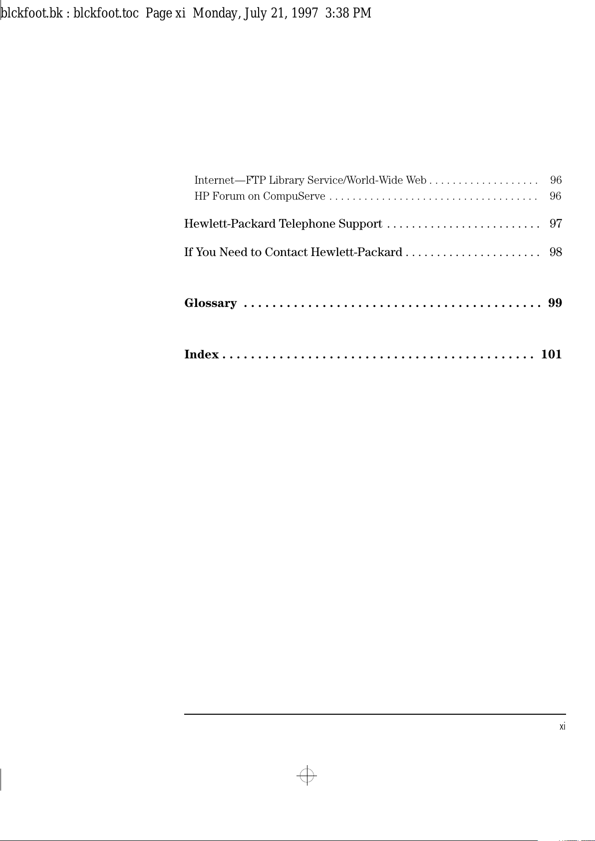
English xi
Internet—FTP Library Service/World-Wide Web . . . . . . . . . . . . . . . . . . . 96
HP Forum on CompuServe . . . . . . . . . . . . . . . . . . . . . . . . . . . . . . . . . . . . 96
Hewlett-Packard Telephone Support . . . . . . . . . . . . . . . . . . . . . . . . . 97
If You Need to Contact Hewlett-Packard . . . . . . . . . . . . . . . . . . . . . . 98
Glossary . . . . . . . . . . . . . . . . . . . . . . . . . . . . . . . . . . . . . . . . . . 99
Index . . . . . . . . . . . . . . . . . . . . . . . . . . . . . . . . . . . . . . . . . . . . 101
blckfoot.bk : blckfoot.toc Page xi Monday, July 21, 1997 3:38 PM
Page 12
xii English
blckfoot.bk : blckfoot.toc Page xii Monday, July 21, 1997 3:38 PM
Page 13
1
Setting Up Your PC
This chapter leads you through the first time installation of your
HP Vectra PC.
blckfoot.bk : chapter1.fb4 Page 1 Monday, July 21, 1997 3:38 PM
Page 14
1 Setting Up Your PC
Unpacking Your PC
2 English
Unpacking Your PC
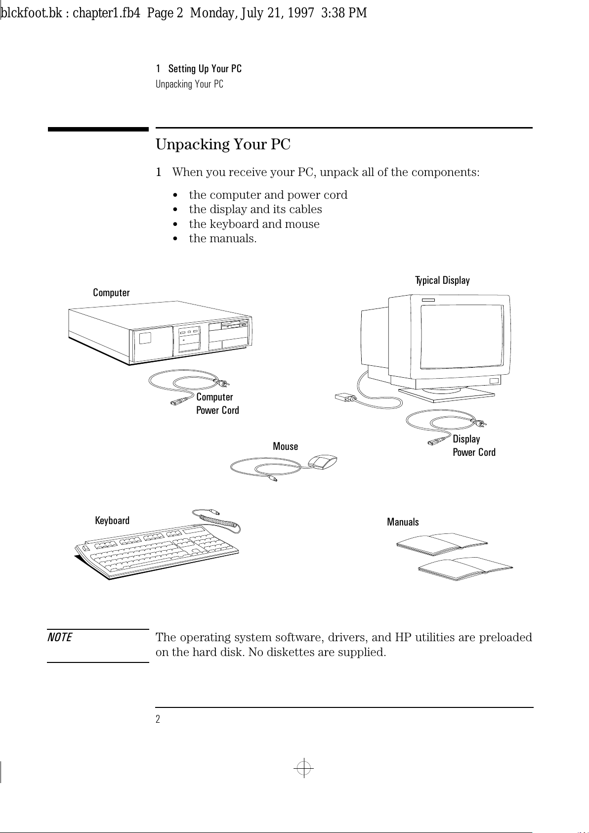
1
When you receive your PC, unpack all of the components:
•
the computer and power cord
•
the display and its cables
•
the keyboard and mouse
•
the manuals.
NOTE The operating system software, drivers, and HP utilities are preloaded
on the hard disk. No diskettes are supplied.
Computer
Power Cord
Computer
Typical Display
Mouse
Keyboard
Manuals
Display
Power Cord
blckfoot.bk : chapter1.fb4 Page 2 Monday, July 21, 1997 3:38 PM
Page 15
English 3
1 Setting Up Your PC
Unpacking Your PC
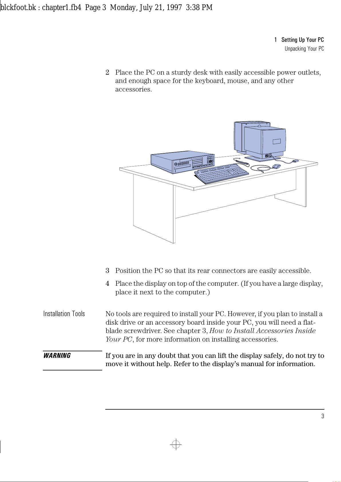
2 Place the PC on a sturdy desk with easily accessible power outlets,
and enough space for the keyboard, mouse, and any other
accessories.
3 Position the PC so that its rear connectors are easily accessible.
4 Place the display on top of the computer. (If you have a large display,
place it next to the computer.)
Installation Tools
No tools are required to install your PC. However, if you plan to install a
disk drive or an accessory board inside your PC, you will need a flat-
blade screwdriver. See chapter 3, How to Install Accessories Inside
Your PC, for more information on installing accessories.
WARNING
If you are in any doubt that you can lift the display safely, do not try to
move it without help. Refer to the display’s manual for information.
blckfoot.bk : chapter1.fb4 Page 3 Monday, July 21, 1997 3:38 PM
Page 16
1 Setting Up Your PC
Connecting the Mouse, Keyboard, and Display
4 English
Connecting the Mouse, Keyboard, and Display
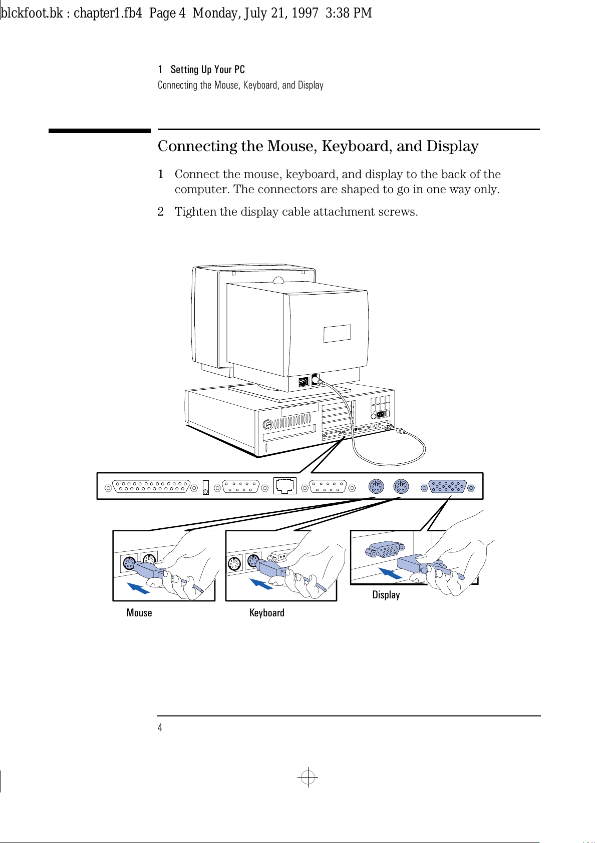
1
Connect the mouse, keyboard, and display to the back of the
computer. The connectors are shaped to go in one way only.
2
Tighten the display cable attachment screws.
Mouse Keyboard
Display
blckfoot.bk : chapter1.fb4 Page 4 Monday, July 21, 1997 3:38 PM
Page 17
English 5
1 Setting Up Your PC
Connecting to a Network
Connecting to a Network
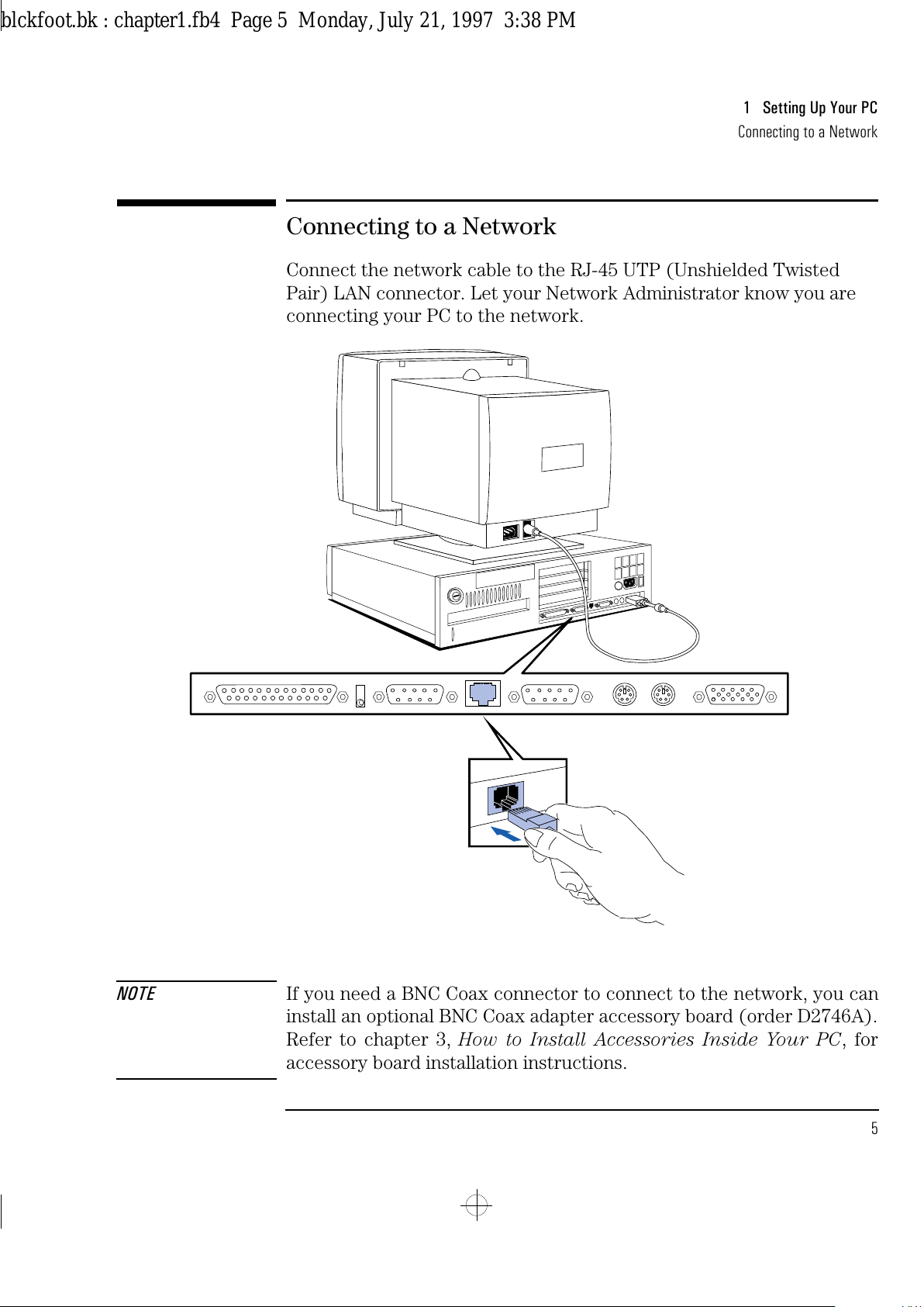
Connect the network cable to the RJ-45 UTP (Unshielded Twisted
Pair) LAN connector. Let your Network Administrator know you are
connecting your PC to the network.
NOTE If you need a BNC Coax connector to connect to the network, you can
install an optional BNC Coax adapter accessory board (order D2746A).
Refer to chapter 3, How to Install Accessories Inside Your PC, for
accessory board installation instructions.
blckfoot.bk : chapter1.fb4 Page 5 Monday, July 21, 1997 3:38 PM
Page 18
1 Setting Up Your PC
Connecting a Printer
6 English
Connecting a Printer
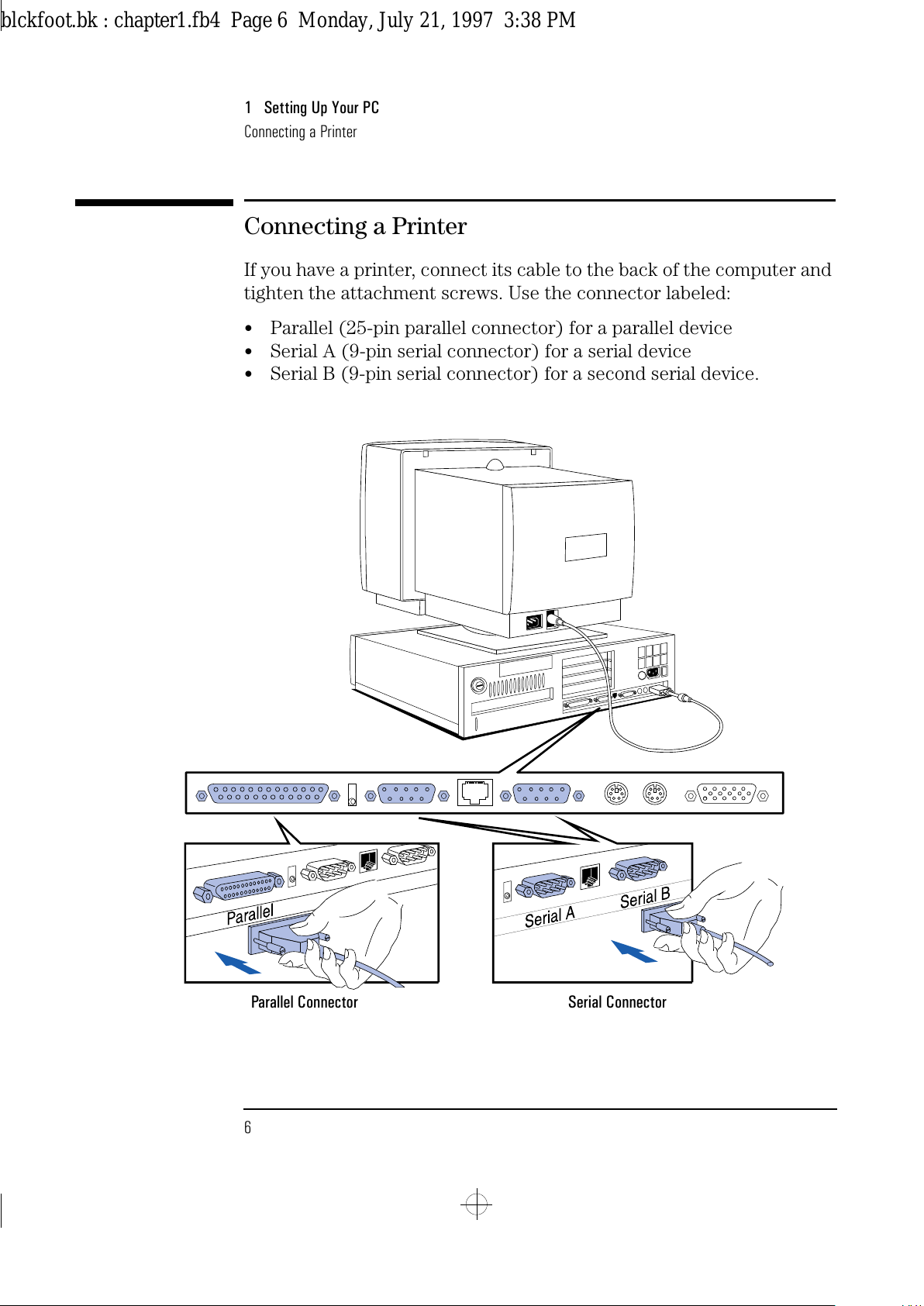
If you have a printer, connect its cable to the back of the computer and
tighten the attachment screws. Use the connector labeled:
•
Parallel (25-pin parallel connector) for a parallel device
•
Serial A (9-pin serial connector) for a serial device
•
Serial B (9-pin serial connector) for a second serial device.
Parallel Connector Serial Connector
blckfoot.bk : chapter1.fb4 Page 6 Monday, July 21, 1997 3:38 PM
Page 19
English 7
1 Setting Up Your PC
Connecting the Power Cords
Connecting the Power Cords
1
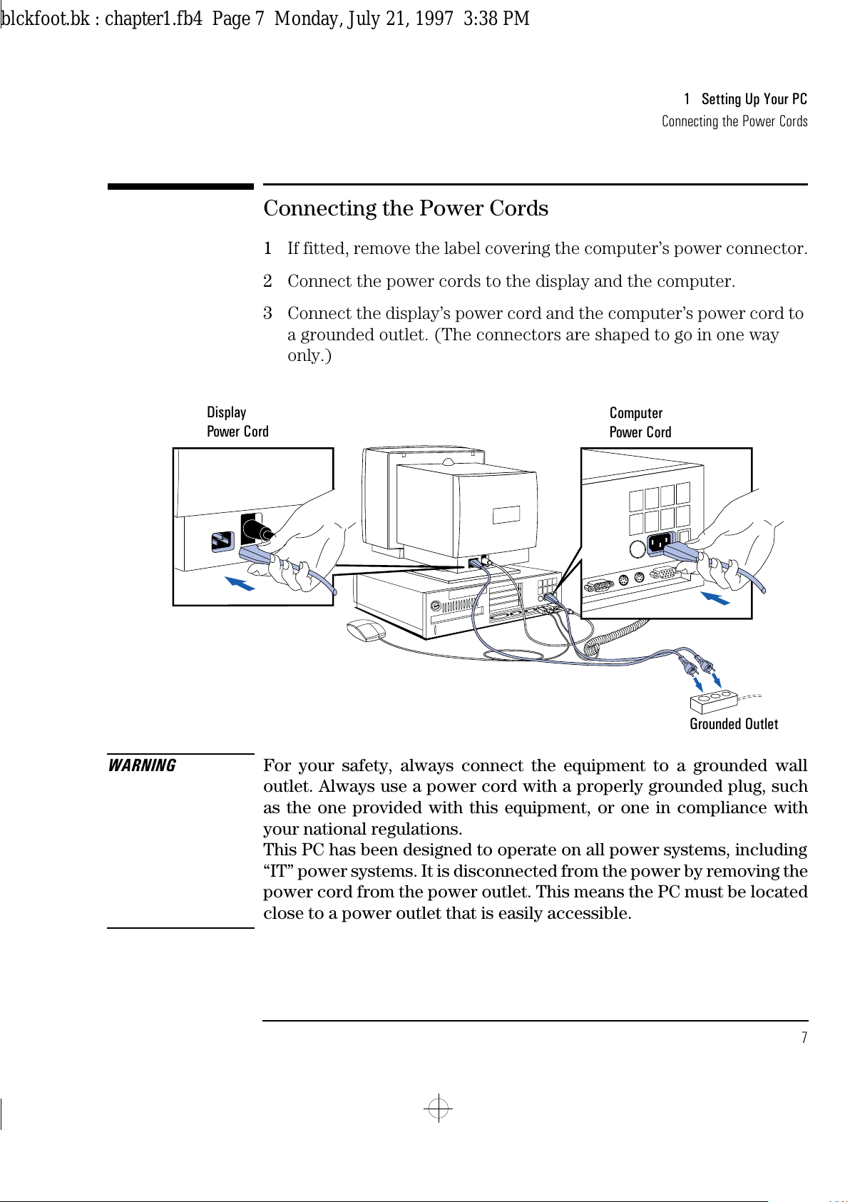
If fitted, remove the label covering the computer’s power connector.
2
Connect the power cords to the display and the computer.
3
Connect the display’s power cord and the computer’s power cord to
a grounded outlet. (The connectors are shaped to go in one way
only.)
WARNING
For your safety, always connect the equipment to a grounded wall
outlet. Always use a power cord with a properly grounded plug, such
as the one provided with this equipment, or one in compliance with
your national regulations.
This PC has been designed to operate on all power systems, including
“IT” power systems. It is disconnected from the power by removing the
power cord from the power outlet. This means the PC must be located
close to a power outlet that is easily accessible.
Display
Power Cord
Computer
Power Cord
Grounded Outlet
blckfoot.bk : chapter1.fb4 Page 7 Monday, July 21, 1997 3:38 PM
Page 20
1 Setting Up Your PC
Starting the PC for the First Time
8 English
Starting the PC for the First Time
Your PC has preinstalled software. This software is initialized the first
time you start the PC. The software initialization takes approximately
three minutes, and:
•
sets up the software in your language
•
sets up your software to use the hardware installed in your
computer—note that you can change the settings after the software
has been initialized.
To initialize your software:
1
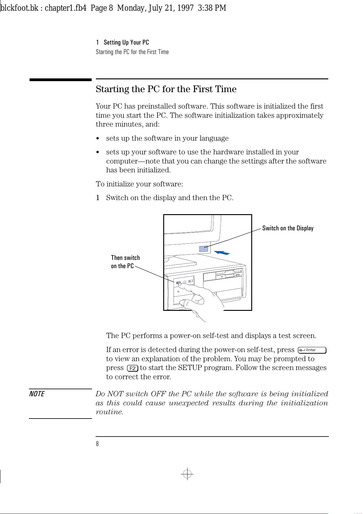
Switch on the display and then the PC.
The PC performs a power-on self-test and displays a test screen.
If an error is detected during the power-on self-test, press
to view an explanation of the problem. You may be prompted to
press to start the SETUP program. Follow the screen messages
to correct the error.
NOTE
Do NOT switch OFF the PC while the software is being initialized
as this could cause unexpected results during the initialization
routine.
Switch on the Display
Then switch
on the PC
blckfoot.bk : chapter1.fb4 Page 8 Monday, July 21, 1997 3:38 PM
Page 21
English 9
1 Setting Up Your PC
Starting the PC for the First Time
2 The software initialization routine starts. It displays the software
license agreement, gives you an opportunity to read Working in
Comfort (ergonomic advice for computer users), and then asks you
questions about the PC. For example:
•
The name of the person who will use the computer and your
company name. (If necessary, the name of the user can be
modified later.)
•
The current date and time.
•
The type of printer (for example, HP LaserJet 4M). This is shown
on the front of the printer. You also need to enter the connection
used by the printer (for example, LPT1 for a parallel printer or
COM1 for a serial printer).
•
The type of network you are going to use your computer with.
You will need to enter the name of the person who will use the
computer, the name of the LAN Workgroup this user will be
connected to, and the name you wish to give this computer.
•
The model number of your display. The display’s model number
is shown on the cover of the manual supplied with the display and
on a label on the rear of the display.
3 While the initialization program is running, complete your Warranty
Registration card (in the back of this manual).
When the initialization routine is finished, click on OK and the PC
will restart.
blckfoot.bk : chapter1.fb4 Page 9 Monday, July 21, 1997 3:38 PM
Page 22
1 Setting Up Your PC
Starting the PC for the First Time
10 English
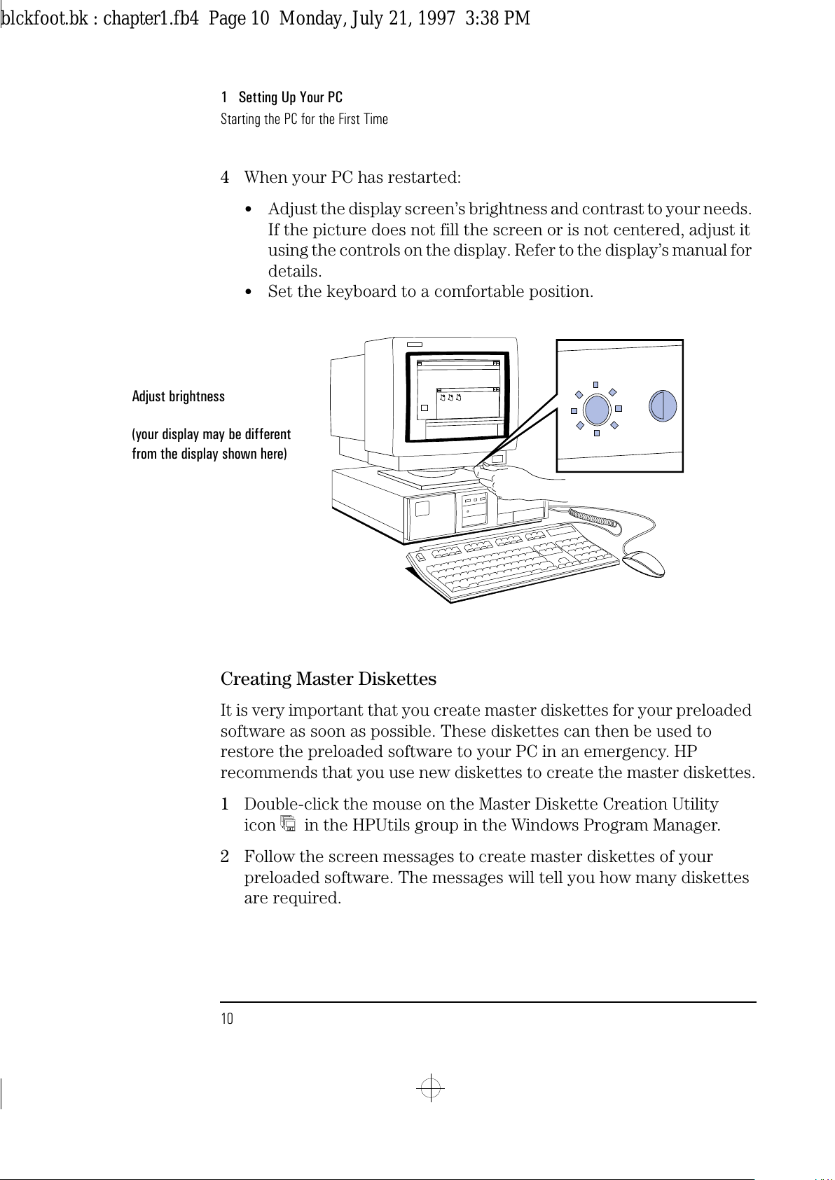
4 When your PC has restarted:
•
Adjust the display screen’s brightness and contrast to your needs.
If the picture does not fill the screen or is not centered, adjust it
using the controls on the display. Refer to the display’s manual for
details.
•
Set the keyboard to a comfortable position.
Creating Master Diskettes
It is very important that you create master diskettes for your preloaded
software as soon as possible. These diskettes can then be used to
restore the preloaded software to your PC in an emergency. HP
recommends that you use new diskettes to create the master diskettes.
1 Double-click the mouse on the Master Diskette Creation Utility
icon in the HPUtils group in the Windows Program Manager.
2 Follow the screen messages to create master diskettes of your
preloaded software. The messages will tell you how many diskettes
are required.
Adjust brightness
(your display may be different
from the display shown here)
blckfoot.bk : chapter1.fb4 Page 10 Monday, July 21, 1997 3:38 PM
Page 23
2
Using Your PC
This chapter explains how to use the HP Vectra features and tools
designed to increase your productivity.
blckfoot.bk : chapter2.fb4 Page 11 Monday, July 21, 1997 3:38 PM
Page 24
2 Using Your PC
Starting and Stopping Your PC
12 English
Starting and Stopping Your PC
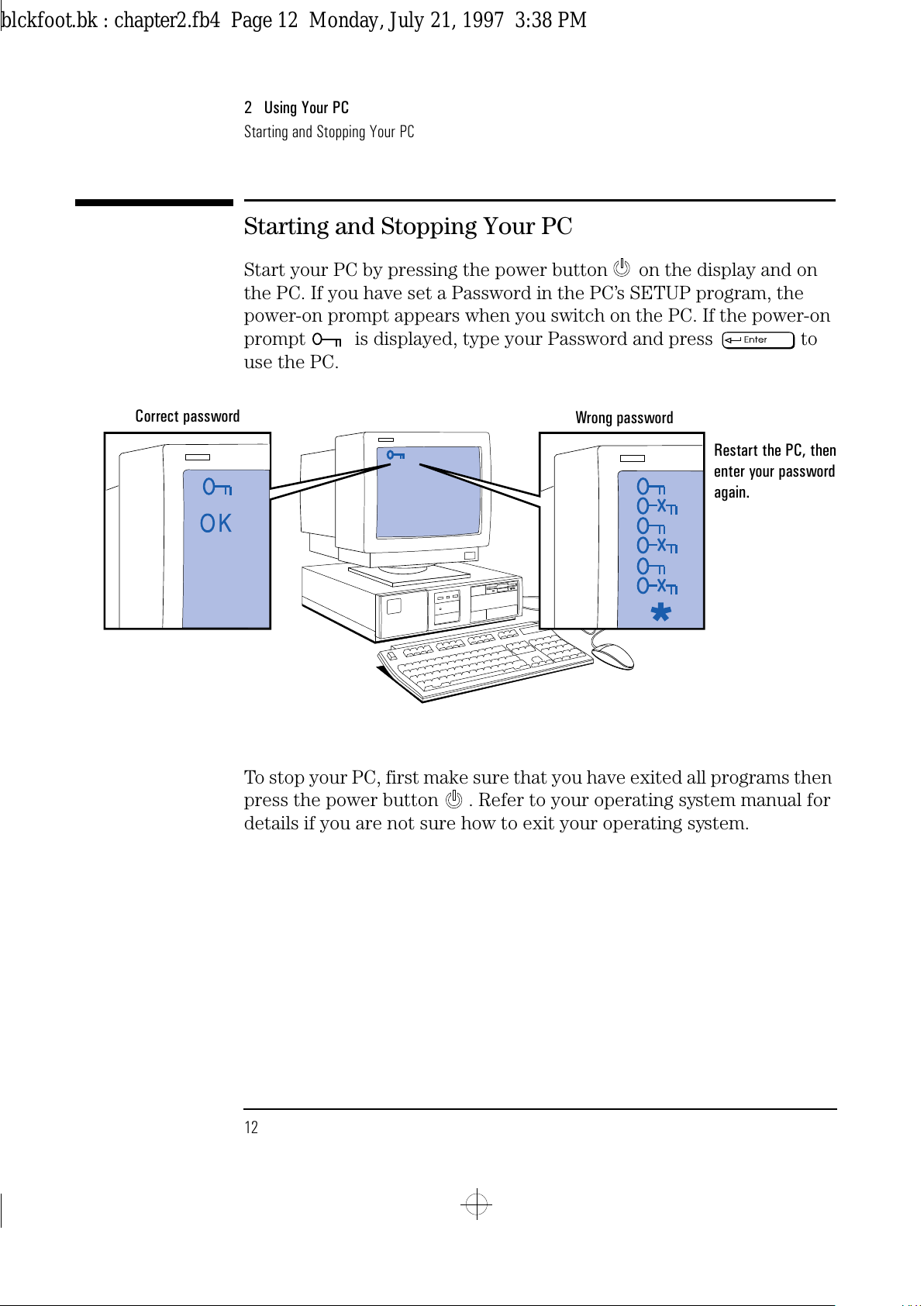
Start your PC by pressing the power button on the display and on
the PC. If you have set a Password in the PC’s SETUP program, the
power-on prompt appears when you switch on the PC. If the power-on
prompt is displayed, type your Password and press to
use the PC.
To stop your PC, first make sure that you have exited all programs then
press the power button . Refer to your operating system manual for
details if you are not sure how to exit your operating system.
Correct password
Restart the PC, then
enter your password
again.
Wrong password
blckfoot.bk : chapter2.fb4 Page 12 Monday, July 21, 1997 3:38 PM
Page 25
English 13
2 Using Your PC
Configuring Password Security
Configuring Password Security
You can set two passwords, which can be used to provide two levels of
protection for your PC.
User Password
The User Password provides these security features:
•
a power-on password prompt to prevent your PC being started in
your absence
•
a keyboard lock timer which you can use to lock your PC after a
specified number of minutes of keyboard inactivity
•
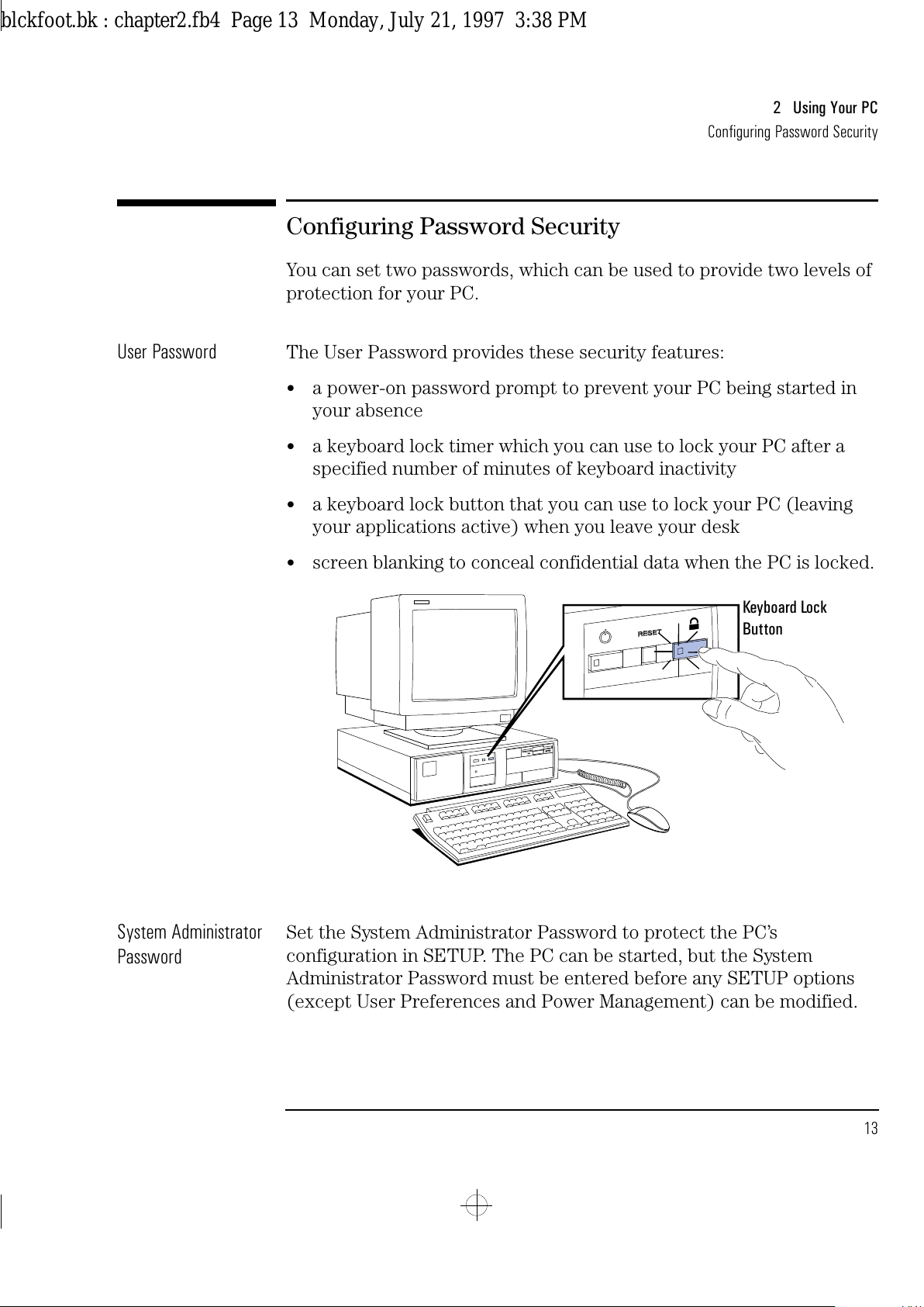
a keyboard lock button that you can use to lock your PC (leaving
your applications active) when you leave your desk
•
screen blanking to conceal confidential data when the PC is locked.
System Administrator
Password
Set the System Administrator Password to protect the PC’s
configuration in SETUP. The PC can be started, but the System
Administrator Password must be entered before any SETUP options
(except User Preferences and Power Management) can be modified.
Keyboard Lock
Button
blckfoot.bk : chapter2.fb4 Page 13 Monday, July 21, 1997 3:38 PM
Page 26
2 Using Your PC
Configuring Password Security
14 English
Setting a Password
1
Turn on the PC and the display.
If the PC is already turned on, exit all applications and then press
and to restart the PC.
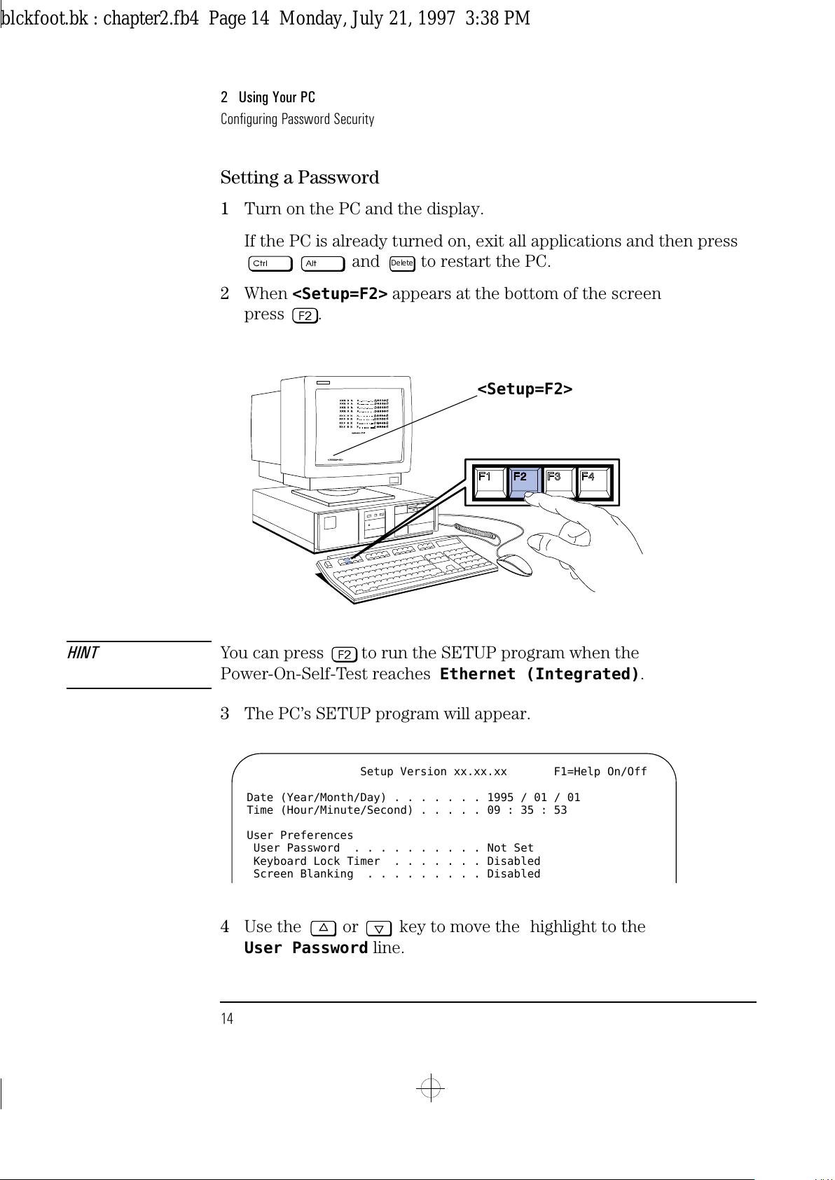
2
When
<Setup=F2>
appears at the bottom of the screen
press .
HINT You can press to run the SETUP program when the
Power-On-Self-Test reaches
Ethernet (Integrated)
.
3
The PC’s SETUP program will appear.
4
Use the or key to move the highlight to the
User Password
line.
Delete
<Setup=F2>
Setup Version xx.xx.xx F1=Help On/Off
Date (Year/Month/Day) . . . . . . . 1995 / 01 / 01
Time (Hour/Minute/Second) . . . . . 09 : 35 : 53
User Preferences
User Password . . . . . . . . . . Not Set
Keyboard Lock Timer . . . . . . . Disabled
Screen Blanking . . . . . . . . . Disabled
blckfoot.bk : chapter2.fb4 Page 14 Monday, July 21, 1997 3:38 PM
Page 27
English 15
2 Using Your PC
Configuring Password Security
5 To set your User Password, press once.
a Type your password and press .
b Type your password and press again.
The screen displays
User Password . . . . . . . Set
6 If you wish to erase your Password, press twice.
If you only want to set a password, press the key now to save
your password and exit SETUP.
Setting the Keyboard
Lock Timer
7 Press the key until the
Keyboard Lock Timer
line is
highlighted.
8 Press or to select a value between 1 and 75 minutes.
If you wish to save this setting and leave SETUP, press the key
now.
Setting Screen Blanking
9 Press the key until the
Screen Blanking
line is highlighted.
10 Press or to select
Screen Blanking . . . Enabled
.
11 Use the key to save this setting and exit SETUP.
blckfoot.bk : chapter2.fb4 Page 15 Monday, July 21, 1997 3:38 PM
Page 28
2 Using Your PC
Introducing the HP Utilities
16 English
Introducing the HP Utilities
The Hewlett-Packard Utilities are located in the Hputils group in the
Windows program manager. These utilities include:
❒
Discover Your HP Vectra
an online introduction to the main features of your PC
❒
Network Administrator Guide
a guide to configuring your PC for different network operating
systems (this guide exists in English only)
❒
Network Setup
a setup program for your Windows network connections
❒
Master Diskette Creation utility
an utility for creating master diskettes of your preloaded software
❒
HP PCID
a program which lets you create a personalized message, which will
appear during your PC’s power-on self-test
❒
HP User Tools
the HP User Tools are described below.
Using the HP User Tools
The HP User Tools let you select a better Windows video resolution,
configure your printer, set the date and time, change the user name,
read the Working in Comfort document (ergonomic information), and
read the license agreement for your preinstalled software.
To access the HP User Tools:
1
Double-click on the Hputils group icon to display the Hewlett-
Packard utilities.
2
Double-click on the HP User Tools icon to display the HP User
Tools utility.
3
Click on the button of the tool that you wish to use.
blckfoot.bk : chapter2.fb4 Page 16 Monday, July 21, 1997 3:38 PM
Page 29
English 17
2 Using Your PC
Introducing the HP Utilities
Some Buttons You May Need To Use
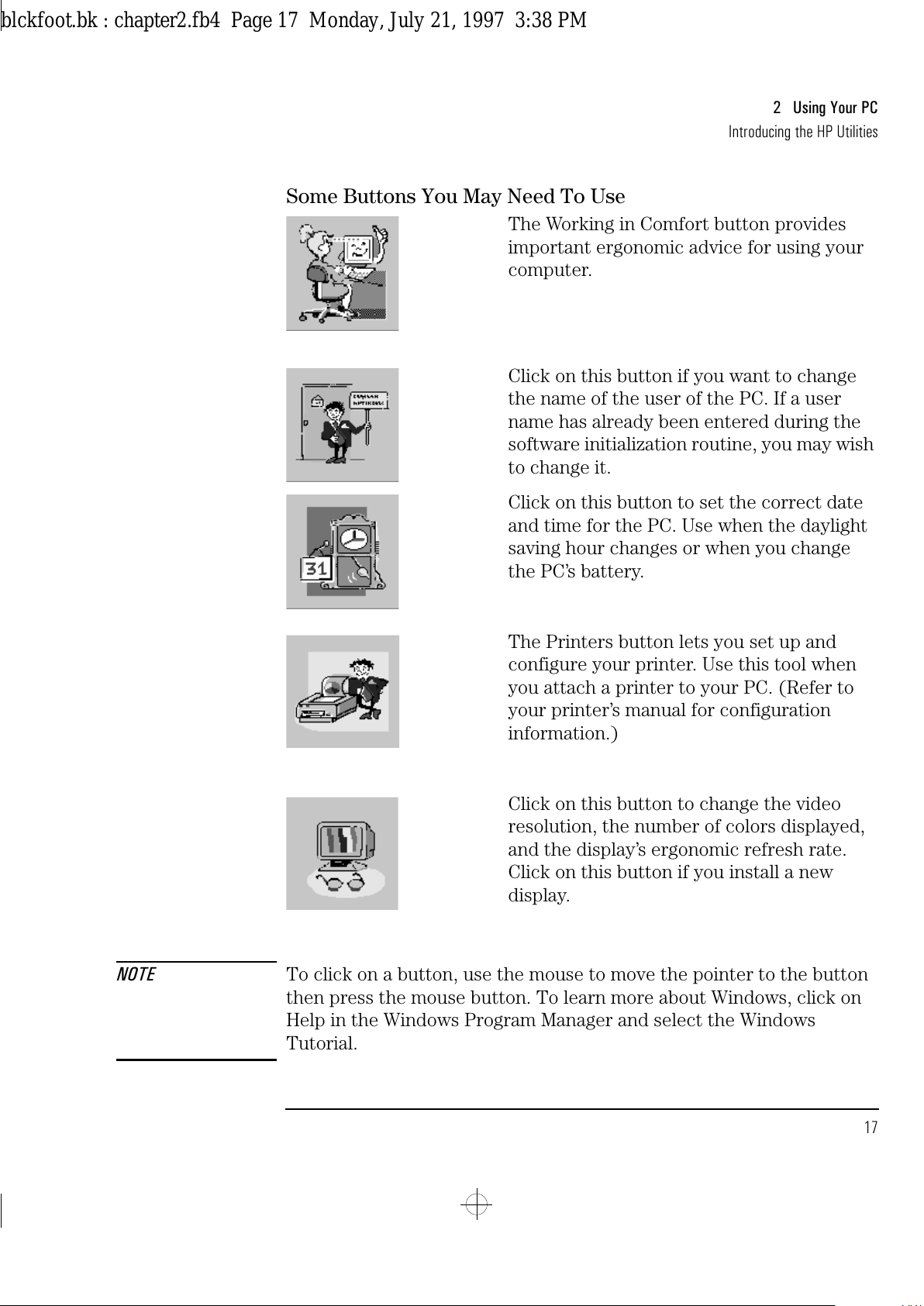
The Working in Comfort button provides
important ergonomic advice for using your
computer.
Click on this button if you want to change
the name of the user of the PC. If a user
name has already been entered during the
software initialization routine, you may wish
to change it.
Click on this button to set the correct date
and time for the PC. Use when the daylight
saving hour changes or when you change
the PC’s battery.
The Printers button lets you set up and
configure your printer. Use this tool when
you attach a printer to your PC. (Refer to
your printer’s manual for configuration
information.)
Click on this button to change the video
resolution, the number of colors displayed,
and the display’s ergonomic refresh rate.
Click on this button if you install a new
display.
NOTE To click on a button, use the mouse to move the pointer to the button
then press the mouse button. To learn more about Windows, click on
Help in the Windows Program Manager and select the Windows
Tutorial.
blckfoot.bk : chapter2.fb4 Page 17 Monday, July 21, 1997 3:38 PM
Page 30
2 Using Your PC
Understanding Power Management
18 English
Understanding Power Management
Your PC supports a power management system which complies with
the EPA (Environmental Protection Agency) Energy Star program. You
can use power management to reduce the power used by your PC
when you aren’t using it. Two power management modes are
supported:
•
Standby mode reduces power consumption significantly
•
Sleep mode reduces power consumption to a minimum.
Configuring Power
Management in
Windows
1
Double-click on the Main Group icon to display the Main
program group.
2
Double-click on the Control Panel icon .
3
Double-click on the Power icon to display the Power dialog box.
4
Select the Advanced mode.
5
Click on Options and the Setup Power Management dialog box
appears.
6
Select the “Standby” timeout (set to 30 min., by default), the “Sleep
At” time (set to Off, by default), or both.
NOTE Click on the Advanced button to configure your PC to be woken up by a
call coming into a fax/modem, or to select a hard disk sleep mode.
7
Click on OK to close the Setup Power Management dialog box.
8
Click on OK to enable Power Management in Windows.
Activating Sleep Mode
in Windows
To activate Sleep mode, click on the Sleep Mode icon (at the
bottom-left of the screen).
To return to full power mode, press any key.
Power Management in
DOS
For more information about the DOS power management utility, at the
DOS prompt type
HELP POWER
and press .
blckfoot.bk : chapter2.fb4 Page 18 Monday, July 21, 1997 3:38 PM
Page 31
English 19
2 Using Your PC
Personalizing Your Mouse
Personalizing Your Mouse
Your PC has preinstalled Windows software which lets you personalize
the functionality of your mouse.
1
Double-click on the Mouse Software group icon to display the
Mouse Software.
2
Double-click on the Mouse Control Center icon in the
Windows Program manager to display the Mouse Control Center.
3
Click on the Help button for more information about the Mouse
Control Center.
Understanding the Desktop Management Interface
Your PC supports the Desktop Management Interface (DMI). The DMI
lets an application request information about your computer. For
example, an application can use the DMI to view:
•
the hardware and software components installed in your PC
•
the operating system used by your PC
•
the number of available accessory board slots.
All this information is stored in a Management Information Format
(MIF) file, installed on your PC as part of the DMI package.
To install the DMI demonstration application and learn more about the
Desktop Management Interface:
1
Double-click on the DMI group icon in the Windows Program
Manager.
2
Double-click on the DMI Readme icon for up-to-date
information about the DMI support for your PC.
3
Double-click on the DMI Setup icon to install the DMI
demonstration application on your PC.
blckfoot.bk : chapter2.fb4 Page 19 Monday, July 21, 1997 3:38 PM
Page 32
2 Using Your PC
Tips for Using Your PC
20 English
Tips for Using Your PC
If you want to: You need to:
1 Install hardware accessories. Refer to chapter 3 “How to Install Accessories
Inside Your PC”.
2 Configure hardware accessories. Refer to chapter 3 “How to Install Accessories
Inside Your PC”.
3 Install new applications, and set up and use
an application.
Read the manuals supplied with the application
software.
4 Start a Windows application. Double-click on its icon.
5 Switch to another application that is running
under Windows.
Press and simultaneously.
6 Change the mouse double-click and tracking
speed, and left-hand or right-hand mouse
buttons.
Use the Mouse Control Center icon.
7 Set up your network connection. Use the Network Setup icon in the HPutils group.
8 Set up a printer. Use the Printers icon in the HP User Tools.
9 Make more disk space available. Delete unnecessary files and increase disk space
by using a disk compression program.
Install a larger disk drive.
10 Make more memory available. Install more main memory. Refer to chapter 3.
11 Display more colors. Use the Video Mode icon in the HP User Tools.
Install more video memory. Refer to chapter 3.
12 Stop anyone from starting the PC in your
absence.
Run the built-in SETUP program and set a
Password. Refer to chapter 2 for details.
blckfoot.bk : chapter2.fb4 Page 20 Monday, July 21, 1997 3:38 PM
Page 33
3
How to Install Accessories
Inside Your PC
This chapter explains how to install accessories, such as extra memory,
accessory boards, and additional disk drives, in your PC.
blckfoot.bk : chapter3.fb4 Page 21 Monday, July 21, 1997 3:38 PM
Page 34
3 How to Install Accessories Inside Your PC
Supported HP Accessories
22 English
Supported HP Accessories
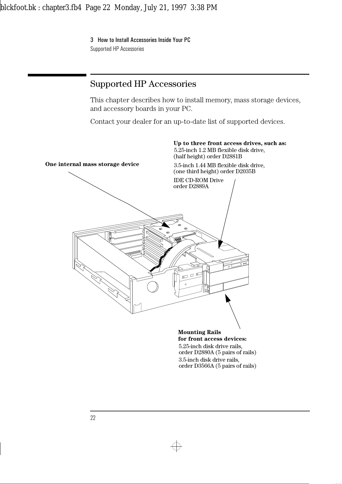
This chapter describes how to install memory, mass storage devices,
and accessory boards in your PC.
Contact your dealer for an up-to-date list of supported devices.
Up to three front access drives, such as:
5.25-inch 1.2 MB flexible disk drive,
(half height) order D2881B
3.5-inch 1.44 MB flexible disk drive,
(one third height) order D2035B
IDE CD-ROM Drive
order D2889A
One internal mass storage device
Mounting Rails
5.25-inch disk drive rails,
order D2880A (5 pairs of rails)
for front access devices:
3.5-inch disk drive rails,
order D3566A (5 pairs of rails)
blckfoot.bk : chapter3.fb4 Page 22 Monday, July 21, 1997 3:38 PM
Page 35
English 23
3 How to Install Accessories Inside Your PC
Supported HP Accessories
WARNING
For your safety, never remove the PC’s cover without first removing
the power cord, and any connection to a telecommunications network.
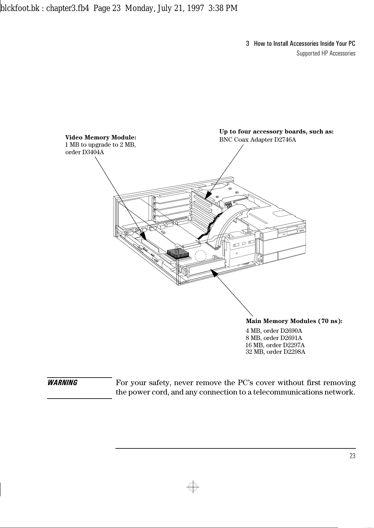
Main Memory Modules (70 ns):
4 MB, order D2690A
8 MB, order D2691A
16 MB, order D2297A
32 MB, order D2298A
Video Memory Module:
1 MB to upgrade to 2 MB,
order D3404A
Up to four accessory boards, such as:
BNC Coax Adapter D2746A
blckfoot.bk : chapter3.fb4 Page 23 Monday, July 21, 1997 3:38 PM
Page 36
3 How to Install Accessories Inside Your PC
Removing and Replacing the Cover
24 English
Removing and Replacing the Cover
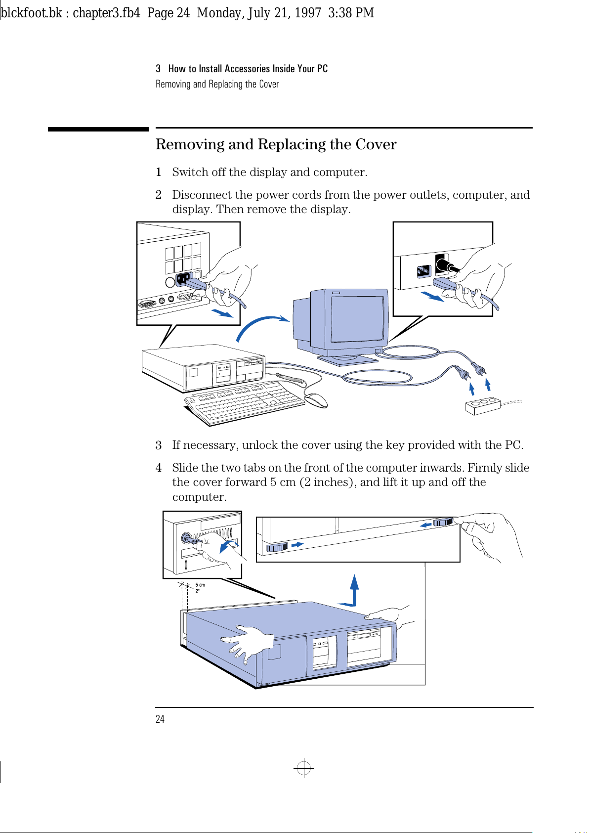
1
Switch off the display and computer.
2
Disconnect the power cords from the power outlets, computer, and
display. Then remove the display.
3
If necessary, unlock the cover using the key provided with the PC.
4
Slide the two tabs on the front of the computer inwards. Firmly slide
the cover forward 5 cm (2 inches), and lift it up and off the
computer.
blckfoot.bk : chapter3.fb4 Page 24 Monday, July 21, 1997 3:38 PM
Page 37
English 25
3 How to Install Accessories Inside Your PC
Removing and Replacing the Cover
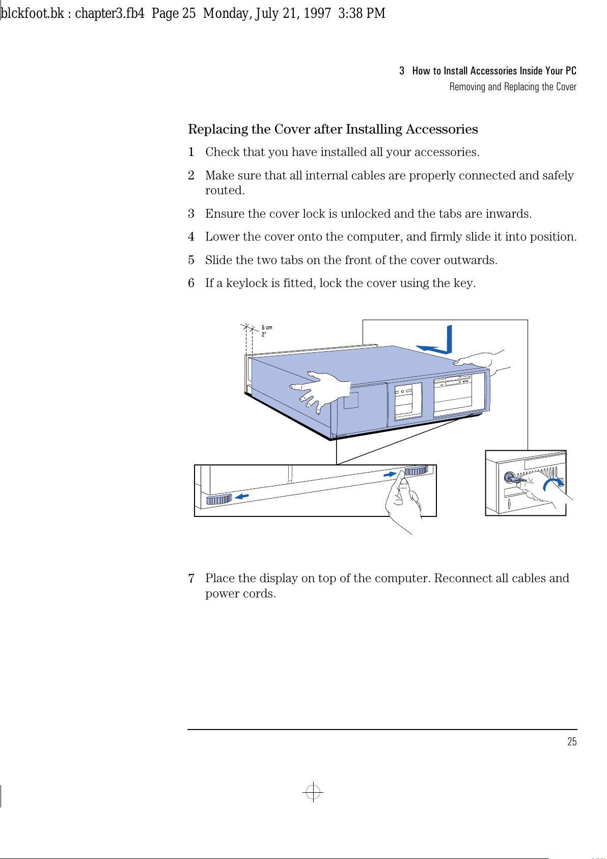
Replacing the Cover after Installing Accessories
1
Check that you have installed all your accessories.
2
Make sure that all internal cables are properly connected and safely
routed.
3
Ensure the cover lock is unlocked and the tabs are inwards.
4
Lower the cover onto the computer, and firmly slide it into position.
5
Slide the two tabs on the front of the cover outwards.
6
If a keylock is fitted, lock the cover using the key.
7
Place the display on top of the computer. Reconnect all cables and
power cords.
blckfoot.bk : chapter3.fb4 Page 25 Monday, July 21, 1997 3:38 PM
Page 38
3 How to Install Accessories Inside Your PC
Removing and Replacing the Power Supply
26 English
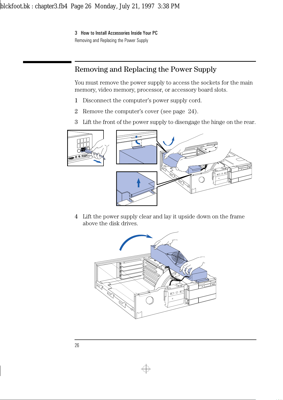
Removing and Replacing the Power Supply
You must remove the power supply to access the sockets for the main
memory, video memory, processor, or accessory board slots.
1
Disconnect the computer’s power supply cord.
2
Remove the computer’s cover (see page 24).
3
Lift the front of the power supply to disengage the hinge on the rear.
4
Lift the power supply clear and lay it upside down on the frame
above the disk drives.
blckfoot.bk : chapter3.fb4 Page 26 Monday, July 21, 1997 3:38 PM
Page 39
English 27
3 How to Install Accessories Inside Your PC
Removing and Replacing the Power Supply
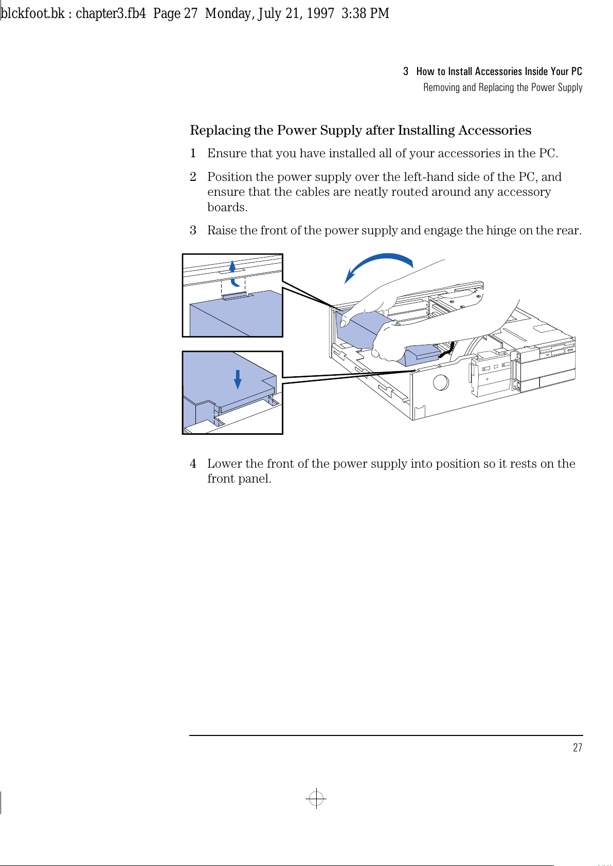
Replacing the Power Supply after Installing Accessories
1
Ensure that you have installed all of your accessories in the PC.
2
Position the power supply over the left-hand side of the PC, and
ensure that the cables are neatly routed around any accessory
boards.
3
Raise the front of the power supply and engage the hinge on the rear.
4
Lower the front of the power supply into position so it rests on the
front panel.
blckfoot.bk : chapter3.fb4 Page 27 Monday, July 21, 1997 3:38 PM
Page 40
3 How to Install Accessories Inside Your PC
Installing Memory
28 English
Installing Memory
Main Memory Modules
Your PC is supplied with main memory. If you need more main memory
to run your application software, you can install up to a total of 192 MB.
Main memory is available in modules of 4 MB, 8 MB, 16 MB, or 32 MB.
Memory modules must be installed from bank A, up to bank C. When
two modules are installed in a bank, they must be the same size. For a
list of available modules, refer to the beginning of this chapter.
WARNING
Static electricity can damage electronic components. Turn all
equipment OFF. Don’t let your clothes touch the accessory.
To equalize the static electricity, rest the accessory bag on top of the
power supply while you are removing the accessory from the bag.
Handle the accessory as little as possible and with care.
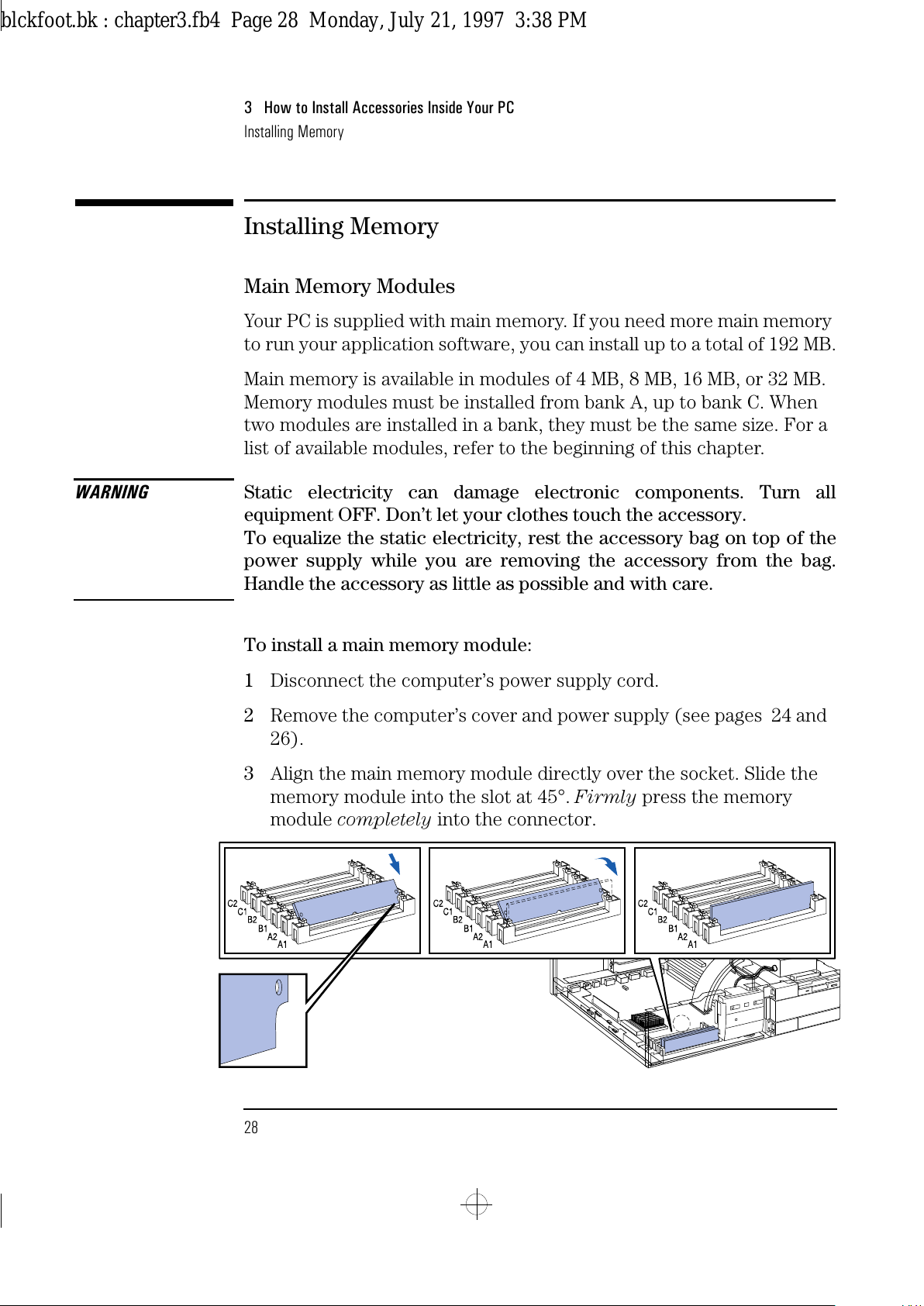
To install a main memory module:
1
Disconnect the computer’s power supply cord.
2
Remove the computer’s cover and power supply (see pages 24 and
26).
3
Align the main memory module directly over the socket. Slide the
memory module into the slot at 45°. Firmly press the memory
module completely into the connector.
blckfoot.bk : chapter3.fb4 Page 28 Monday, July 21, 1997 3:38 PM
Page 41
English 29
3 How to Install Accessories Inside Your PC
Installing Memory
4 Pivot the memory module to the vertical position.
5 Repeat this procedure for each memory module you are installing.
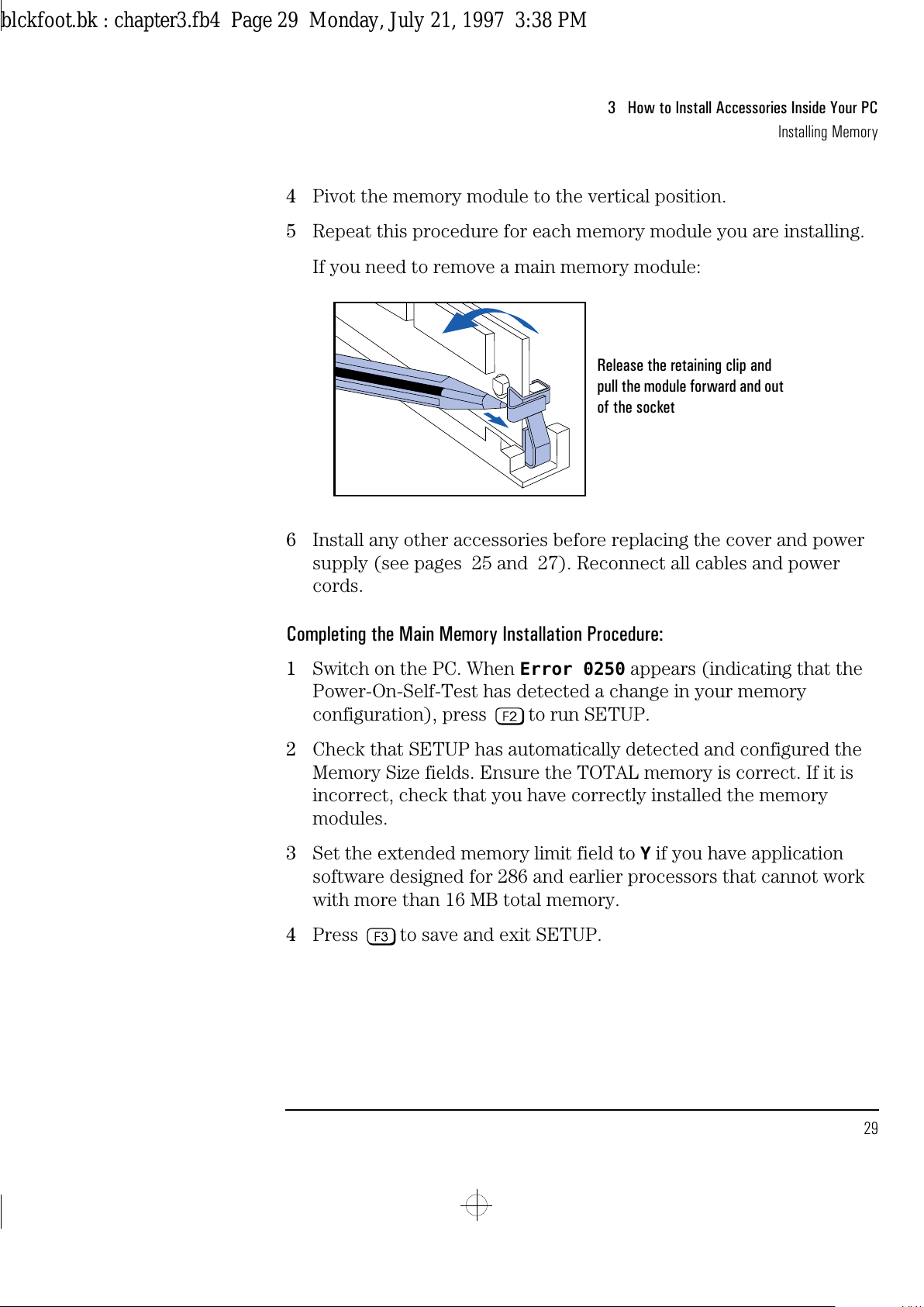
If you need to remove a main memory module:
6 Install any other accessories before replacing the cover and power
supply (see pages 25 and 27). Reconnect all cables and power
cords.
Completing the Main Memory Installation Procedure:
1 Switch on the PC. When
Error 0250
appears (indicating that the
Power-On-Self-Test has detected a change in your memory
configuration), press to run SETUP.
2 Check that SETUP has automatically detected and configured the
Memory Size fields. Ensure the TOTAL memory is correct. If it is
incorrect, check that you have correctly installed the memory
modules.
3 Set the extended memory limit field to
Y
if you have application
software designed for 286 and earlier processors that cannot work
with more than 16 MB total memory.
4 Press to save and exit SETUP.
Release the retaining clip and
pull the module forward and out
of the socket
blckfoot.bk : chapter3.fb4 Page 29 Monday, July 21, 1997 3:38 PM
Page 42
3 How to Install Accessories Inside Your PC
Installing Memory
30 English
Installing a Video Memory Module
Your PC is supplied with 1 MB of video memory. If you need to have
more video memory to display more colors, higher resolutions, or for
increased speed, you can install up to 2 MB inside your PC. The PC has
one socket for a 1 MB video memory module (order D3404A). Some of
the available video resolutions are listed below (refer to page 86 for
more detailed information on video resolutions).
To Install a Video
Memory Module
1
Disconnect the power supply cord.
2
Remove the computer’s cover and power supply (see pages 24 and
26).
3
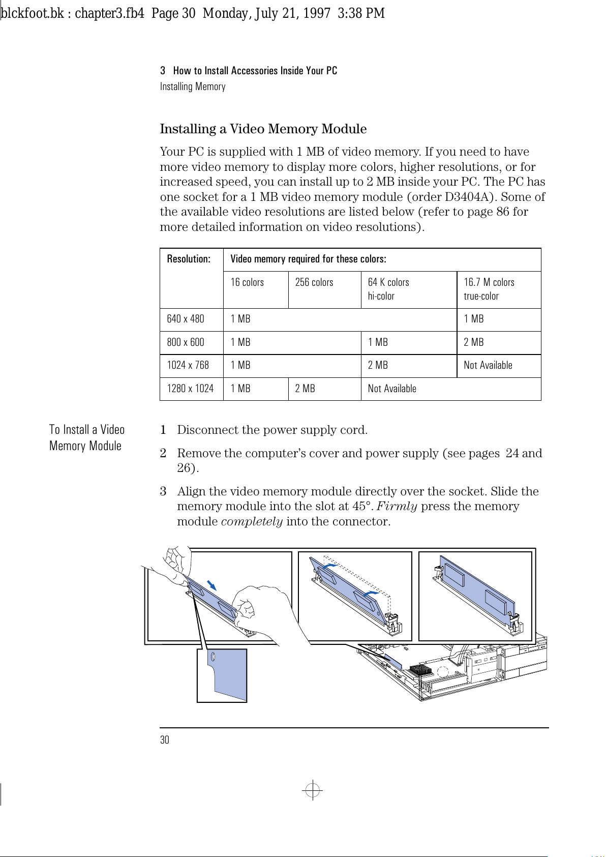
Align the video memory module directly over the socket. Slide the
memory module into the slot at 45°. Firmly press the memory
module completely into the connector.
Resolution: Video memory required for these colors:
16 colors 256 colors 64 K colors
hi-color
16.7 M colors
true-color
640 x 480 1 MB 1 MB
800 x 600 1 MB 1 MB 2 MB
1024 x 768 1 MB 2 MB Not Available
1280 x 1024 1 MB 2 MB Not Available
blckfoot.bk : chapter3.fb4 Page 30 Monday, July 21, 1997 3:38 PM
Page 43
English 31
3 How to Install Accessories Inside Your PC
Installing Memory
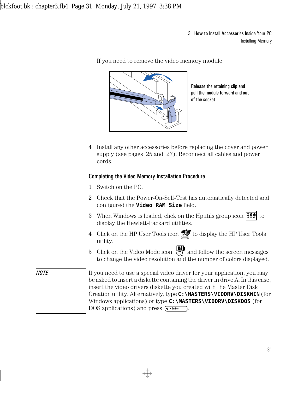
If you need to remove the video memory module:
4 Install any other accessories before replacing the cover and power
supply (see pages 25 and 27). Reconnect all cables and power
cords.
Completing the Video Memory Installation Procedure
1 Switch on the PC.
2 Check that the Power-On-Self-Test has automatically detected and
configured the
Video RAM Size
field.
3 When Windows is loaded, click on the Hputils group icon to
display the Hewlett-Packard utilities.
4 Click on the HP User Tools icon to display the HP User Tools
utility.
5 Click on the Video Mode icon and follow the screen messages
to change the video resolution and the number of colors displayed.
NOTE If you need to use a special video driver for your application, you may
be asked to insert a diskette containing the driver in drive A. In this case,
insert the video drivers diskette you created with the Master Disk
Creation utility. Alternatively, type
C:\MASTERS\VIDDRV\DISKWIN
(for
Windows applications) or type
C:\MASTERS\VIDDRV\DISKDOS
(for
DOS applications) and press .
Release the retaining clip and
pull the module forward and out
of the socket
blckfoot.bk : chapter3.fb4 Page 31 Monday, July 21, 1997 3:38 PM
Page 44
3 How to Install Accessories Inside Your PC
Installing Accessory Boards
32 English
Installing Accessory Boards
The PC has four accessory board slots:
•
Slot 1 (the bottom slot) can be used for half-length 16-bit ISA boards
•
Slot 2 can be used for full-length 16-bit ISA boards
•
Slot 3 can be used for either a full-length 32-bit PCI or
a full-length 16-bit ISA board
•
Slot 4 (the top slot) can be used for a half-length 32-bit PCI board.
Configuring Accessory Boards with Plug and Play
Plug and Play is an industry standard for automatically configuring
your PC's hardware resources and the accessory boards installed in it.
Your PC has configurable support for Plug and Play in the BIOS.
When you start your PC, the Plug and Play BIOS automatically detects
which hardware resources (IRQs, DMAs, memory ranges, and I/O
addresses) are used by the system-based components.
Configuring Plug and
Play with the SETUP
program
You can use the SETUP program to select the level of support provided
by the BIOS for Plug and Play-compatible accessory boards:
1
Turn on the PC and press when
<Setup=F2>
appears.
2
Highlight the
Plug and Play Device Management
line and use
or to select
None, Boot Only
, or
Full
.
•
If
None
is selected, you must use the ISA Configuration Utility
(ICU) to configure all accessory boards.
•
If
Boot Only
is selected, Plug and Play accessory boards which
have the ability to boot (start) your PC will be configured by the
BIOS. You must use the ICU to configure all other accessory
boards.
•
If
Full
is selected, all Plug and Play accessories will be
configured by the BIOS. However, if you install a non-Plug and
Play accessory board, you must use the ICU to determine a
conflict-free setting for the board.
3
Press to save your selection and exit from the SETUP program.
blckfoot.bk : chapter3.fb4 Page 32 Monday, July 21, 1997 3:38 PM
Page 45
English 33
3 How to Install Accessories Inside Your PC
Installing Accessory Boards
Using the ISA Configuration Utility (ICU)
You can use the ICU to configure Plug and Play accessory boards if
Plug and Play Device Management
is set to
None
or
Boot Only
in the SETUP program.
The ICU can also determine the recommended settings for each ISA
non-Plug and Play board you want to install. These settings may be
different from those recommended by the accessory board’s
manufacturer. In this case, the board’s jumper settings and driver
options must be altered.
To run the ICU:
1 Double-click on the Plug and Play group icon in the Windows
Program Manager.
2 Double-click on the ICU Notes icon for up-to-date information
about the Plug and Play support for your PC.
3 Double-click on the ICU User Guide icon for detailed
information about using the ICU.
4 Double-click on the ICU icon to launch the ISA Configuration
Utility and configure system resources for the accessory board.
The ICU is preloaded with configuration details for many non-Plug
and Play accessory boards. If your accessory board is not listed by
the ICU, you have two options:
a Some non-Plug and Play accessory boards are supplied with a
configuration file, which can be used by the ICU to determine
which resources are required by the board. Insert the disk
containing the configuration file when prompted by the ICU.
b If you do not have a configuration file for your accessory board,
you will need to enter the configuration details manually when
prompted by the ICU. Refer to the documentation supplied with
your accessory board for information on the resources required
by the board.
NOTE You do not need to run the ICU when you install a PCI accessory board.
PCI accessory boards are automatically configured when installed in
your PC.
blckfoot.bk : chapter3.fb4 Page 33 Monday, July 21, 1997 3:38 PM
Page 46
3 How to Install Accessories Inside Your PC
Installing Accessory Boards
34 English
Installing the Board
1
Before you install a non-Plug and Play accessory board, run the ISA
Configuration Utility in the Plug and Play group in Windows. See
page 33 for instructions.
NOTE PCI boards are configured automatically when installed in the PC.
2
Disconnect the computer’s power supply cord.
3
Remove the computer’s cover and power supply (see pages 24 and
26).
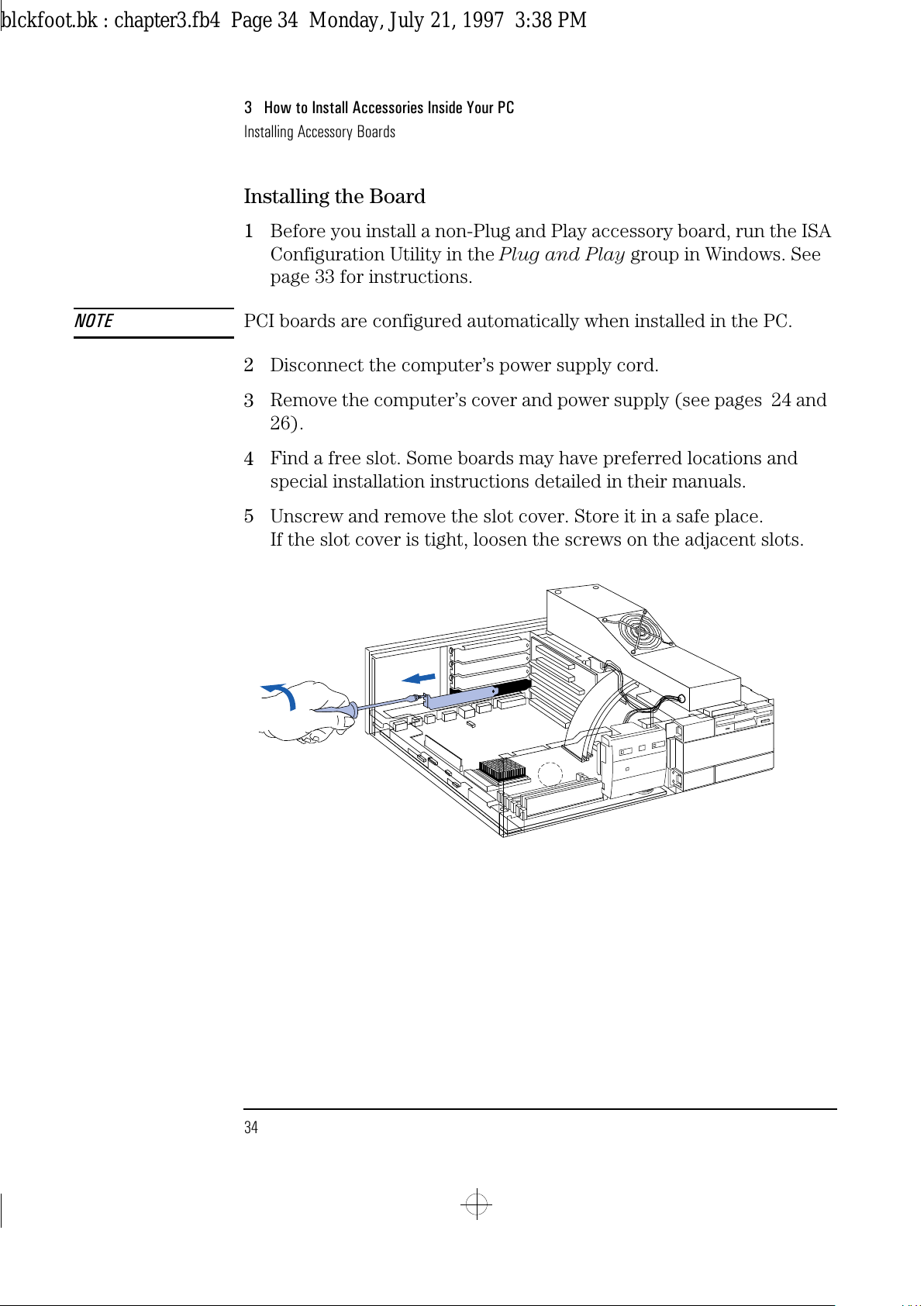
4
Find a free slot. Some boards may have preferred locations and
special installation instructions detailed in their manuals.
5
Unscrew and remove the slot cover. Store it in a safe place.
If the slot cover is tight, loosen the screws on the adjacent slots.
blckfoot.bk : chapter3.fb4 Page 34 Monday, July 21, 1997 3:38 PM
Page 47
English 35
3 How to Install Accessories Inside Your PC
Installing Accessory Boards
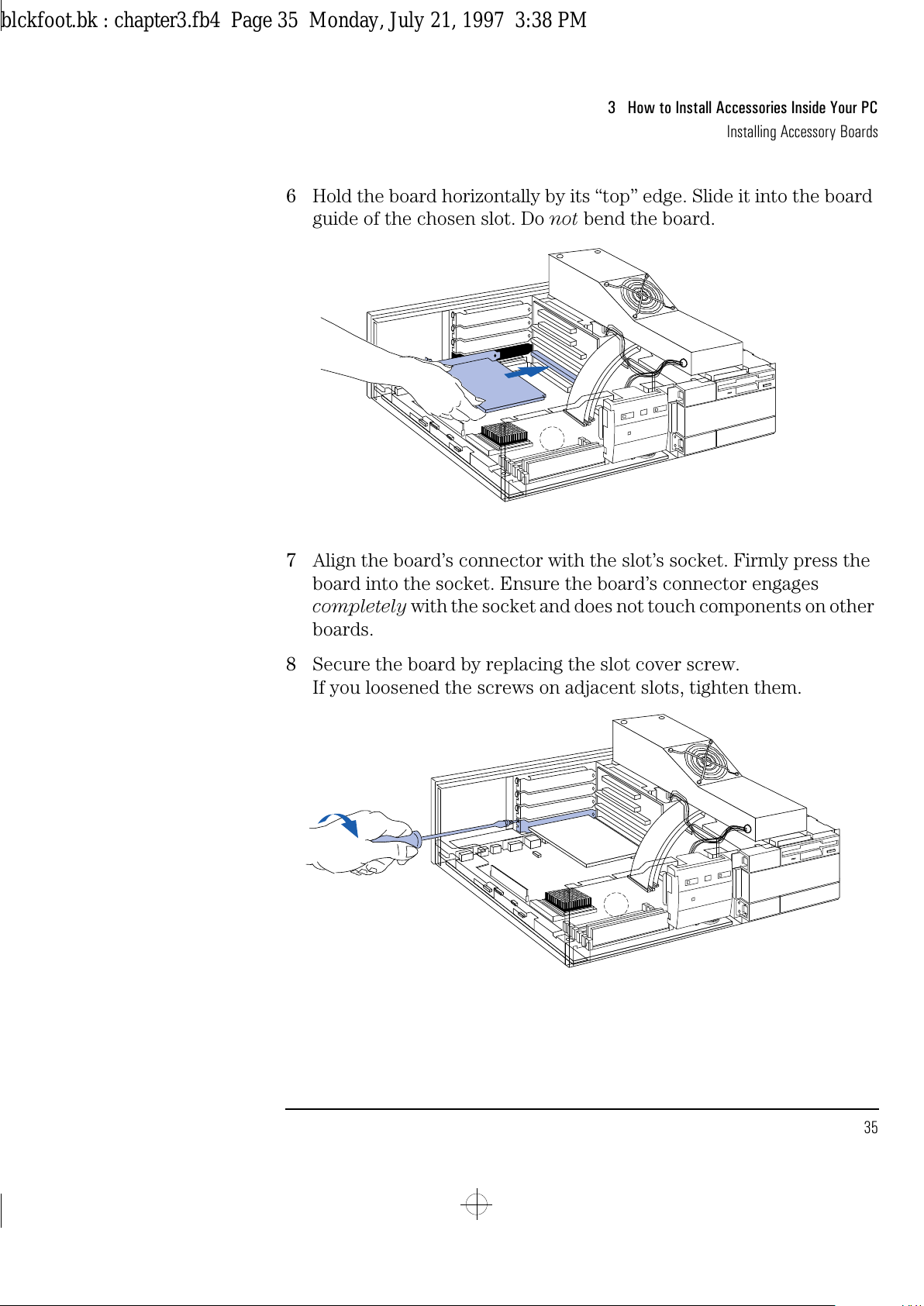
6 Hold the board horizontally by its “top” edge. Slide it into the board
guide of the chosen slot. Do not bend the board.
7 Align the board’s connector with the slot’s socket. Firmly press the
board into the socket. Ensure the board’s connector engages
completely with the socket and does not touch components on other
boards.
8 Secure the board by replacing the slot cover screw.
If you loosened the screws on adjacent slots, tighten them.
blckfoot.bk : chapter3.fb4 Page 35 Monday, July 21, 1997 3:38 PM
Page 48
3 How to Install Accessories Inside Your PC
Installing Accessory Boards
36 English
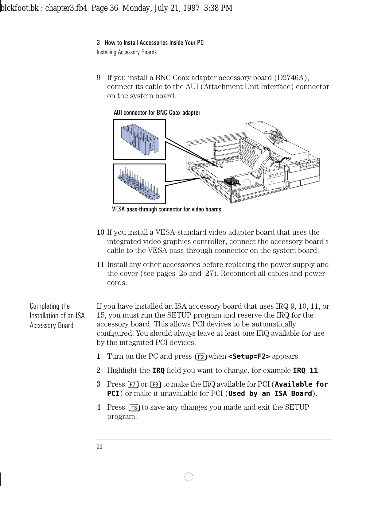
9 If you install a BNC Coax adapter accessory board (D2746A),
connect its cable to the AUI (Attachment Unit Interface) connector
on the system board.
10 If you install a VESA-standard video adapter board that uses the
integrated video graphics controller, connect the accessory board’s
cable to the VESA pass-through connector on the system board.
11 Install any other accessories before replacing the power supply and
the cover (see pages 25 and 27). Reconnect all cables and power
cords.
Completing the
Installation of an ISA
Accessory Board
If you have installed an ISA accessory board that uses IRQ 9, 10, 11, or
15, you must run the SETUP program and reserve the IRQ for the
accessory board. This allows PCI devices to be automatically
configured. You should always leave at least one IRQ available for use
by the integrated PCI devices.
1 Turn on the PC and press when
<Setup=F2>
appears.
2 Highlight the
IRQ
field you want to change, for example
IRQ 11
.
3 Press or to make the IRQ available for PCI (
Available for
PCI
) or make it unavailable for PCI (
Used by an ISA Board
).
4 Press to save any changes you made and exit the SETUP
program.
AUI connector for BNC Coax adapter
VESA pass-through connector for video boards
blckfoot.bk : chapter3.fb4 Page 36 Monday, July 21, 1997 3:38 PM
Page 49
English 37
3 How to Install Accessories Inside Your PC
Installing Mass Storage Devices
Installing Mass Storage Devices
If you need to have extra mass storage space for your application
software, you can install additional mass storage devices.
The PC has one internal drive shelf for a hard disk drive. If your PC
already has a hard disk drive, this shelf will be occupied.
There are three front access drive shelves. The top shelf is occupied by
a 3.5-inch flexible disk drive. The middle shelf may be used to install a
flexible disk drive or a CD-ROM drive. The bottom shelf may be used to
install a second hard disk drive or a 1-inch high, 5.25-inch or 3.5-inch,
front access device.
Your PC has the following connectors on the system board which may
be used by mass storage devices:
•
a flexible disk drive connector
(supporting up to two flexible disk drives)
•
an IDE CD-ROM drive connector
(this connector - colored red - cannot be used for IDE hard disk
drives)
•
an Enhanced IDE hard disk drive connector
(supporting up to two IDE hard disk drives).
Before Installing an
Additional IDE Drive
Create a bootable diskette before installing an additional IDE drive.
Use the Master Diskette Creation utility to create a bootable
master copy of the operating system. This utility is located in the
HPutils group.
For non-DOS/Windows operating systems, refer to the operating
system documentation for information on how to create a bootable
diskette, format a drive, and install the operating system.
NOTE You may install a non-IDE mass storage device, but it will need an
accessory board and driver software (usually supplied with the device).
Contact the product vendor for more information.
blckfoot.bk : chapter3.fb4 Page 37 Monday, July 21, 1997 3:38 PM
Page 50
3 How to Install Accessories Inside Your PC
Installing Mass Storage Devices
38 English
Installing a Flexible Disk Drive or a CD-ROM Drive
in the Middle Shelf
1
Disconnect the computer’s power supply cord.
2
Remove the computer’s cover (see page 24).
3
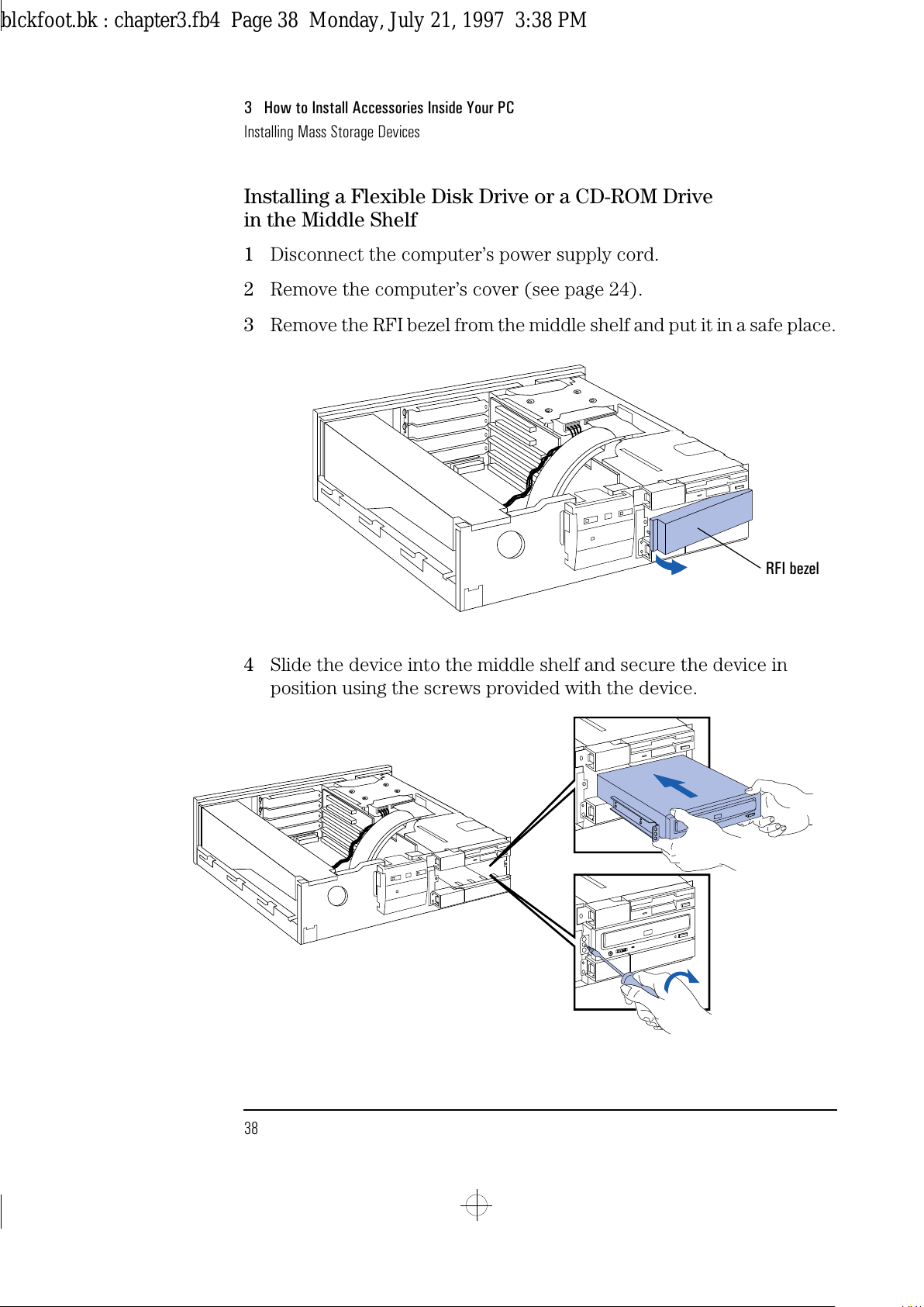
Remove the RFI bezel from the middle shelf and put it in a safe place.
4
Slide the device into the middle shelf and secure the device in
position using the screws provided with the device.
RFI bezel
blckfoot.bk : chapter3.fb4 Page 38 Monday, July 21, 1997 3:38 PM
Page 51
English 39
3 How to Install Accessories Inside Your PC
Installing Mass Storage Devices
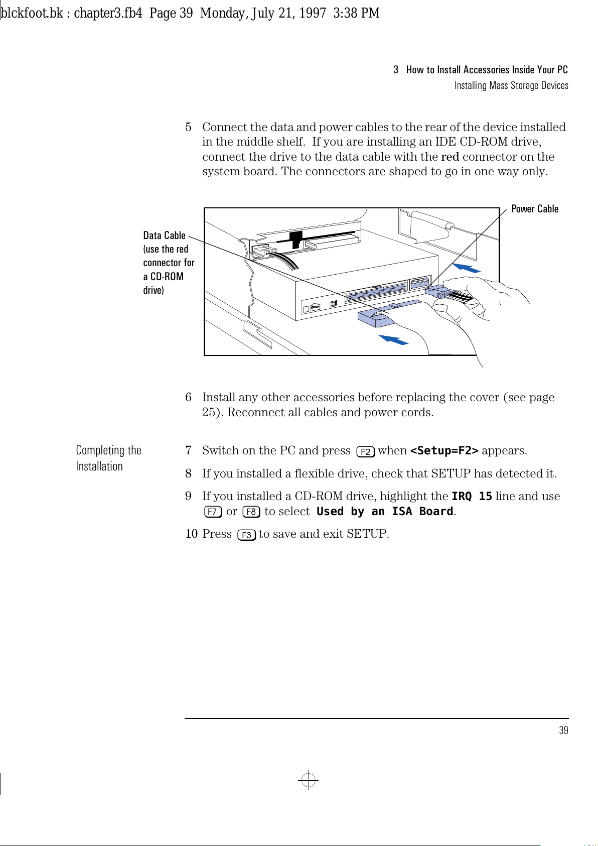
5 Connect the data and power cables to the rear of the device installed
in the middle shelf. If you are installing an IDE CD-ROM drive,
connect the drive to the data cable with the red connector on the
system board. The connectors are shaped to go in one way only.
6 Install any other accessories before replacing the cover (see page
25). Reconnect all cables and power cords.
Completing the
Installation
7 Switch on the PC and press when
<Setup=F2>
appears.
8 If you installed a flexible drive, check that SETUP has detected it.
9 If you installed a CD-ROM drive, highlight the
IRQ 15
line and use
or to select
Used by an ISA Board
.
10 Press to save and exit SETUP.
Power Cable
Data Cable
(use the red
connector for
a CD-ROM
drive)
blckfoot.bk : chapter3.fb4 Page 39 Monday, July 21, 1997 3:38 PM
Page 52
3 How to Install Accessories Inside Your PC
Installing Mass Storage Devices
40 English
Installing an IDE Hard Disk Drive in the Rear Shelf
The PC has an integrated Enhanced IDE controller which supports two
Fast IDE hard disk drives.
Refer to the drive’s manuals to see if you must set jumpers or if there is
a special installation procedure to follow.
1
Disconnect the computer’s power supply cord.
2
Remove the computer’s cover (see page 24).
3
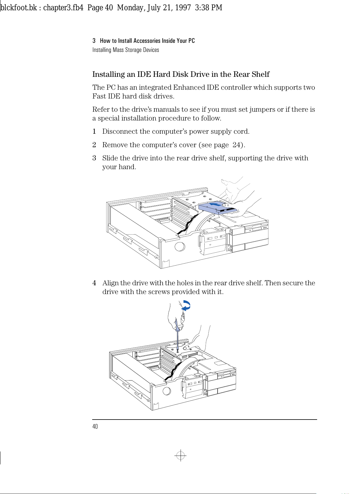
Slide the drive into the rear drive shelf, supporting the drive with
your hand.
4
Align the drive with the holes in the rear drive shelf. Then secure the
drive with the screws provided with it.
blckfoot.bk : chapter3.fb4 Page 40 Monday, July 21, 1997 3:38 PM
Page 53
English 41
3 How to Install Accessories Inside Your PC
Installing Mass Storage Devices
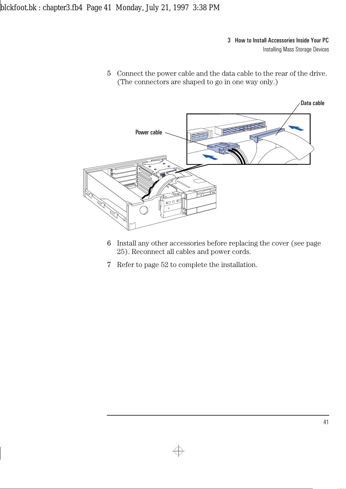
5 Connect the power cable and the data cable to the rear of the drive.
(The connectors are shaped to go in one way only.)
6 Install any other accessories before replacing the cover (see page
25). Reconnect all cables and power cords.
7 Refer to page 52 to complete the installation.
Power cable
Data cable
blckfoot.bk : chapter3.fb4 Page 41 Monday, July 21, 1997 3:38 PM
Page 54
3 How to Install Accessories Inside Your PC
Installing Mass Storage Devices
42 English
Installing an IDE Hard Disk Drive in the Bottom Shelf
The PC has an integrated Enhanced IDE controller which supports two
Fast IDE hard disk drives.
Refer to the drive’s manuals to see if you must set jumpers or if there is
a special installation procedure to follow.
1
Disconnect the computer’s power supply cord.
2
Remove the computer’s cover (see page 24).
3
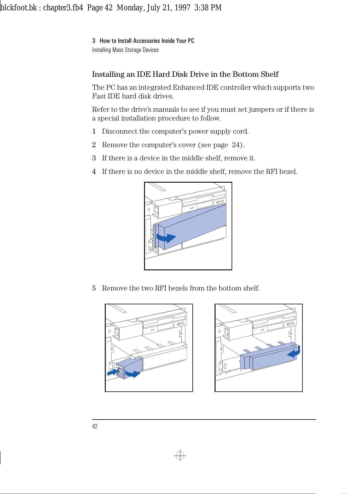
If there is a device in the middle shelf, remove it.
4
If there is no device in the middle shelf, remove the RFI bezel.
5
Remove the two RFI bezels from the bottom shelf.
blckfoot.bk : chapter3.fb4 Page 42 Monday, July 21, 1997 3:38 PM
Page 55
English 43
3 How to Install Accessories Inside Your PC
Installing Mass Storage Devices
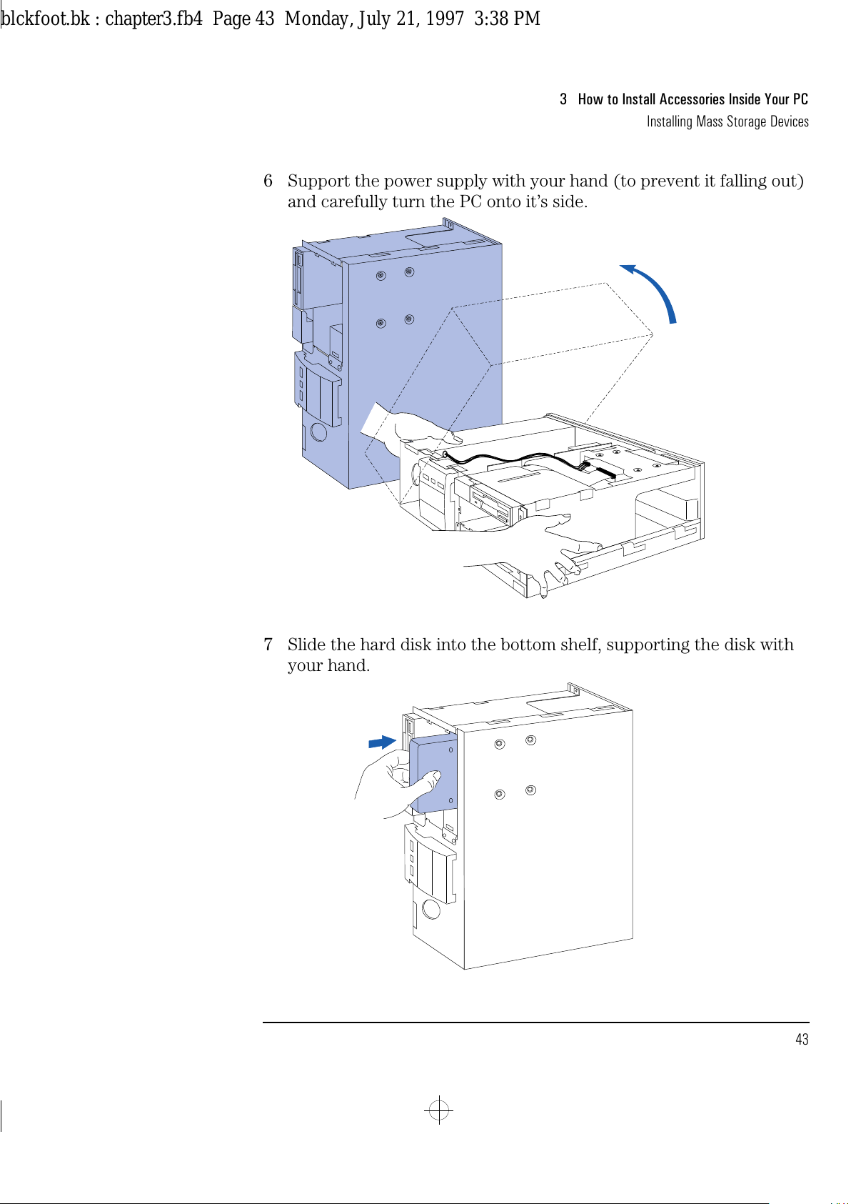
6 Support the power supply with your hand (to prevent it falling out)
and carefully turn the PC onto it’s side.
7 Slide the hard disk into the bottom shelf, supporting the disk with
your hand.
blckfoot.bk : chapter3.fb4 Page 43 Monday, July 21, 1997 3:38 PM
Page 56
3 How to Install Accessories Inside Your PC
Installing Mass Storage Devices
44 English
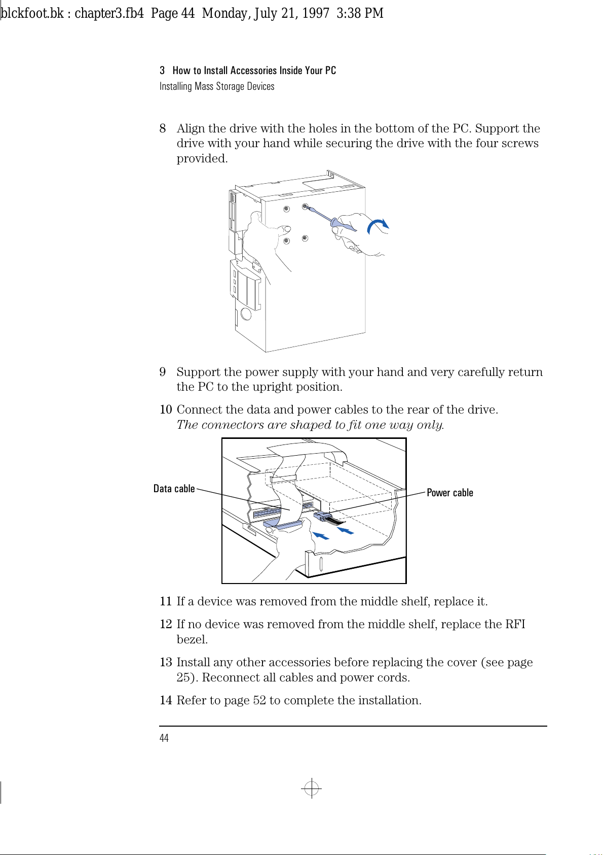
8 Align the drive with the holes in the bottom of the PC. Support the
drive with your hand while securing the drive with the four screws
provided.
9 Support the power supply with your hand and very carefully return
the PC to the upright position.
10 Connect the data and power cables to the rear of the drive.
The connectors are shaped to fit one way only.
11 If a device was removed from the middle shelf, replace it.
12 If no device was removed from the middle shelf, replace the RFI
bezel.
13 Install any other accessories before replacing the cover (see page
25). Reconnect all cables and power cords.
14 Refer to page 52 to complete the installation.
Power cable
Data cable
blckfoot.bk : chapter3.fb4 Page 44 Monday, July 21, 1997 3:38 PM
Page 57
English 45
3 How to Install Accessories Inside Your PC
Installing Mass Storage Devices
Installing a 5.25-inch Drive in the Bottom Shelf
A slim (1-inch high) 5.25-inch front access drive can be installed in the
bottom shelf.
NOTE Disk drives ordered from HP are supplied with mounting rails. If you
order your drive from another supplier, you will need to order drive
mounting rails from HP.
You should order product number D2880A (5.25-inch disk drive rails).
1
Disconnect the computer’s power supply cord.
2
Remove the computer’s cover (see page 24).
3
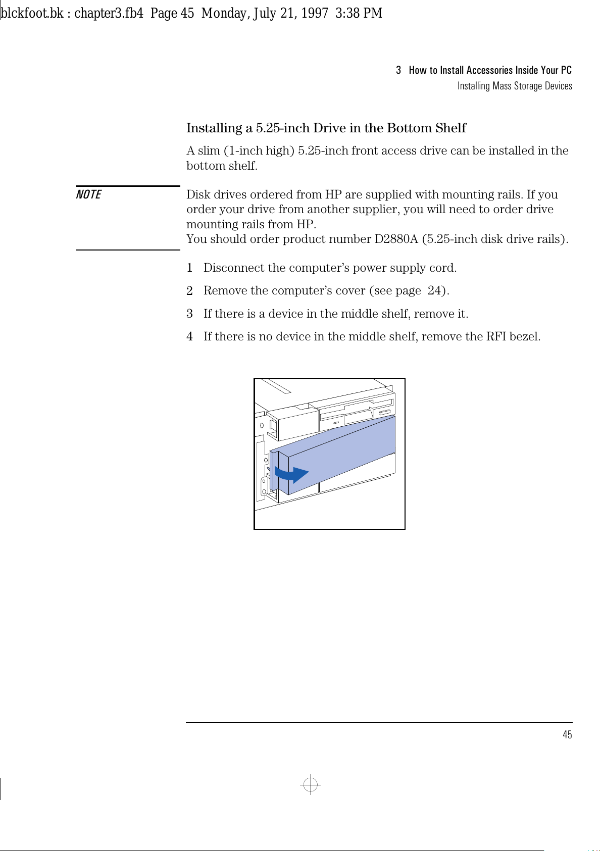
If there is a device in the middle shelf, remove it.
4
If there is no device in the middle shelf, remove the RFI bezel.
blckfoot.bk : chapter3.fb4 Page 45 Monday, July 21, 1997 3:38 PM
Page 58
3 How to Install Accessories Inside Your PC
Installing Mass Storage Devices
46 English
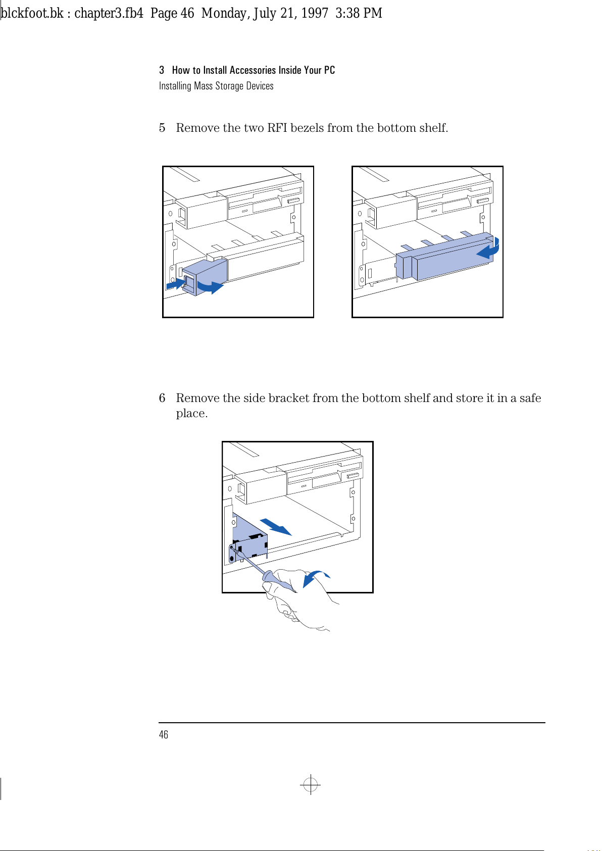
5 Remove the two RFI bezels from the bottom shelf.
6 Remove the side bracket from the bottom shelf and store it in a safe
place.
blckfoot.bk : chapter3.fb4 Page 46 Monday, July 21, 1997 3:38 PM
Page 59
English 47
3 How to Install Accessories Inside Your PC
Installing Mass Storage Devices
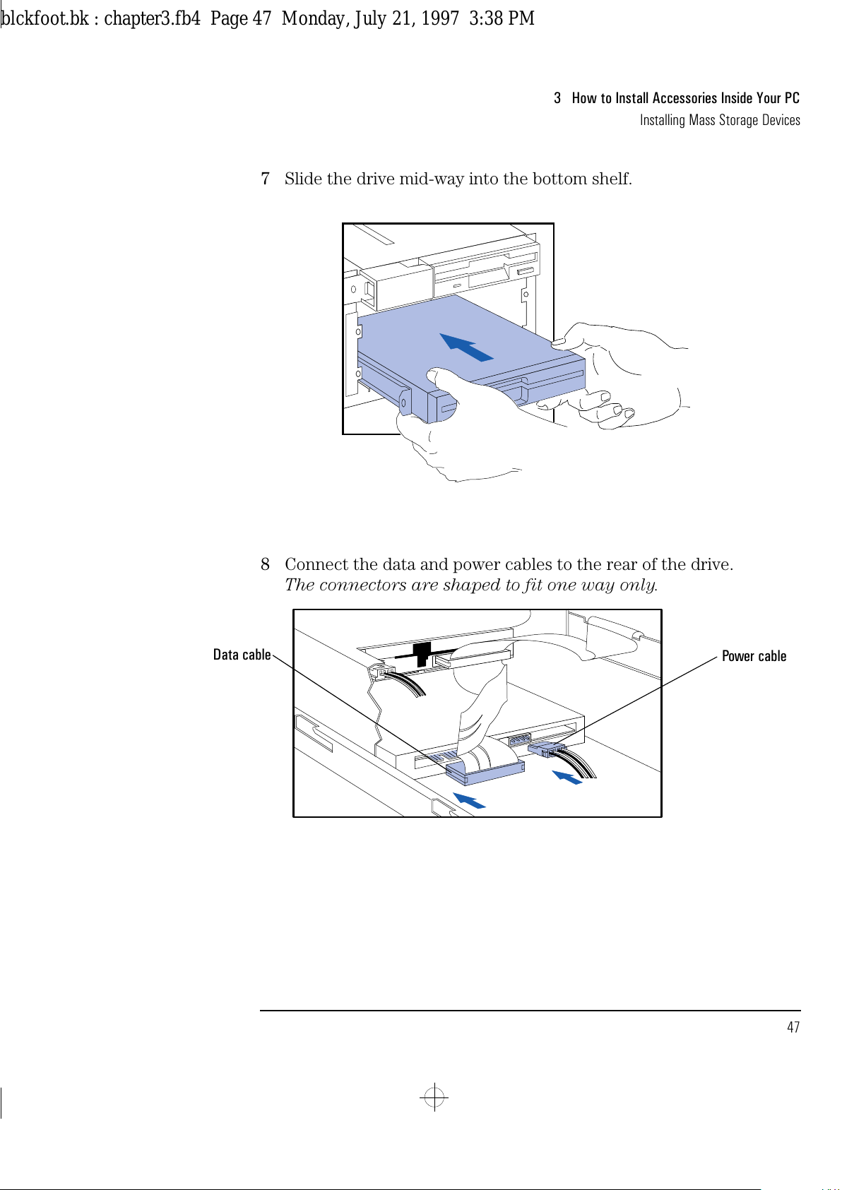
7 Slide the drive mid-way into the bottom shelf.
8 Connect the data and power cables to the rear of the drive.
The connectors are shaped to fit one way only.
Power cable
Data cable
blckfoot.bk : chapter3.fb4 Page 47 Monday, July 21, 1997 3:38 PM
Page 60
3 How to Install Accessories Inside Your PC
Installing Mass Storage Devices
48 English
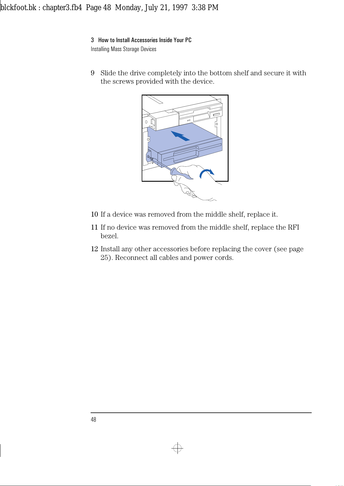
9 Slide the drive completely into the bottom shelf and secure it with
the screws provided with the device.
10 If a device was removed from the middle shelf, replace it.
11 If no device was removed from the middle shelf, replace the RFI
bezel.
12 Install any other accessories before replacing the cover (see page
25). Reconnect all cables and power cords.
blckfoot.bk : chapter3.fb4 Page 48 Monday, July 21, 1997 3:38 PM
Page 61
English 49
3 How to Install Accessories Inside Your PC
Installing Mass Storage Devices
Installing a 3.5-inch Device in the Bottom Shelf
A slim (1-inch high) 3.5-inch front access drive can be installed in the
bottom shelf.
NOTE Disk drives ordered from HP are supplied with mounting rails. If you
order your drive from another supplier, you will need to order drive
mounting rails from HP.
You should order product number D3566A (3.5-inch disk drive rails).
1
Disconnect the computer’s power supply cord.
2
Remove the computer’s cover (see page 24).
3
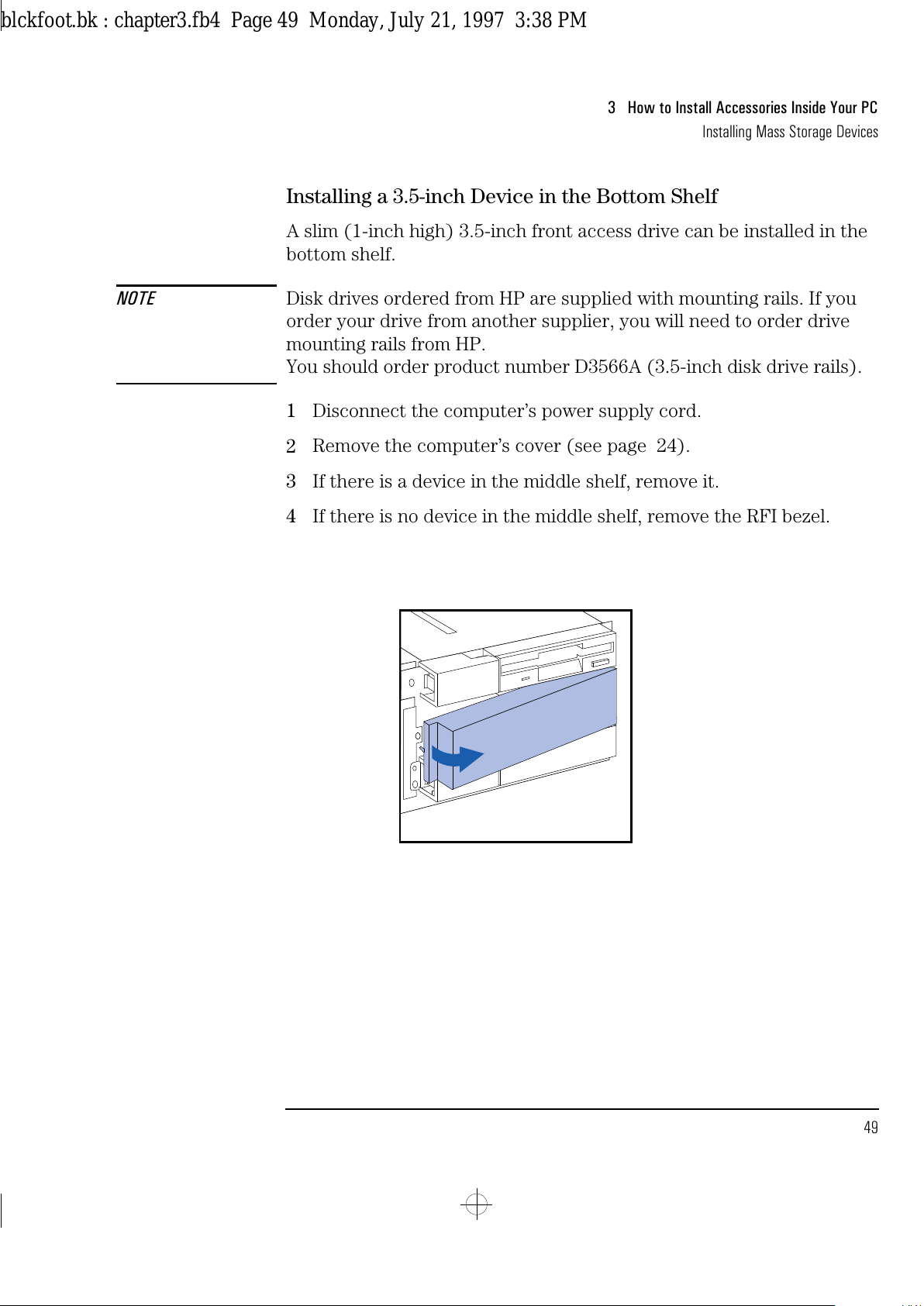
If there is a device in the middle shelf, remove it.
4
If there is no device in the middle shelf, remove the RFI bezel.
blckfoot.bk : chapter3.fb4 Page 49 Monday, July 21, 1997 3:38 PM
Page 62
3 How to Install Accessories Inside Your PC
Installing Mass Storage Devices
50 English
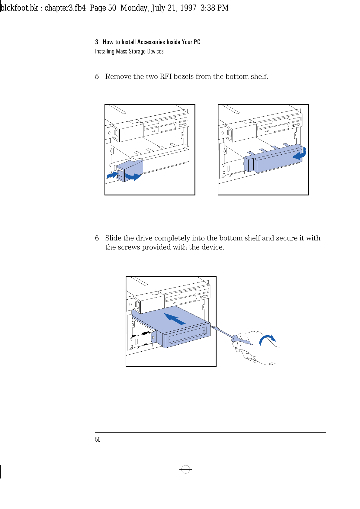
5 Remove the two RFI bezels from the bottom shelf.
6 Slide the drive completely into the bottom shelf and secure it with
the screws provided with the device.
blckfoot.bk : chapter3.fb4 Page 50 Monday, July 21, 1997 3:38 PM
Page 63
English 51
3 How to Install Accessories Inside Your PC
Installing Mass Storage Devices
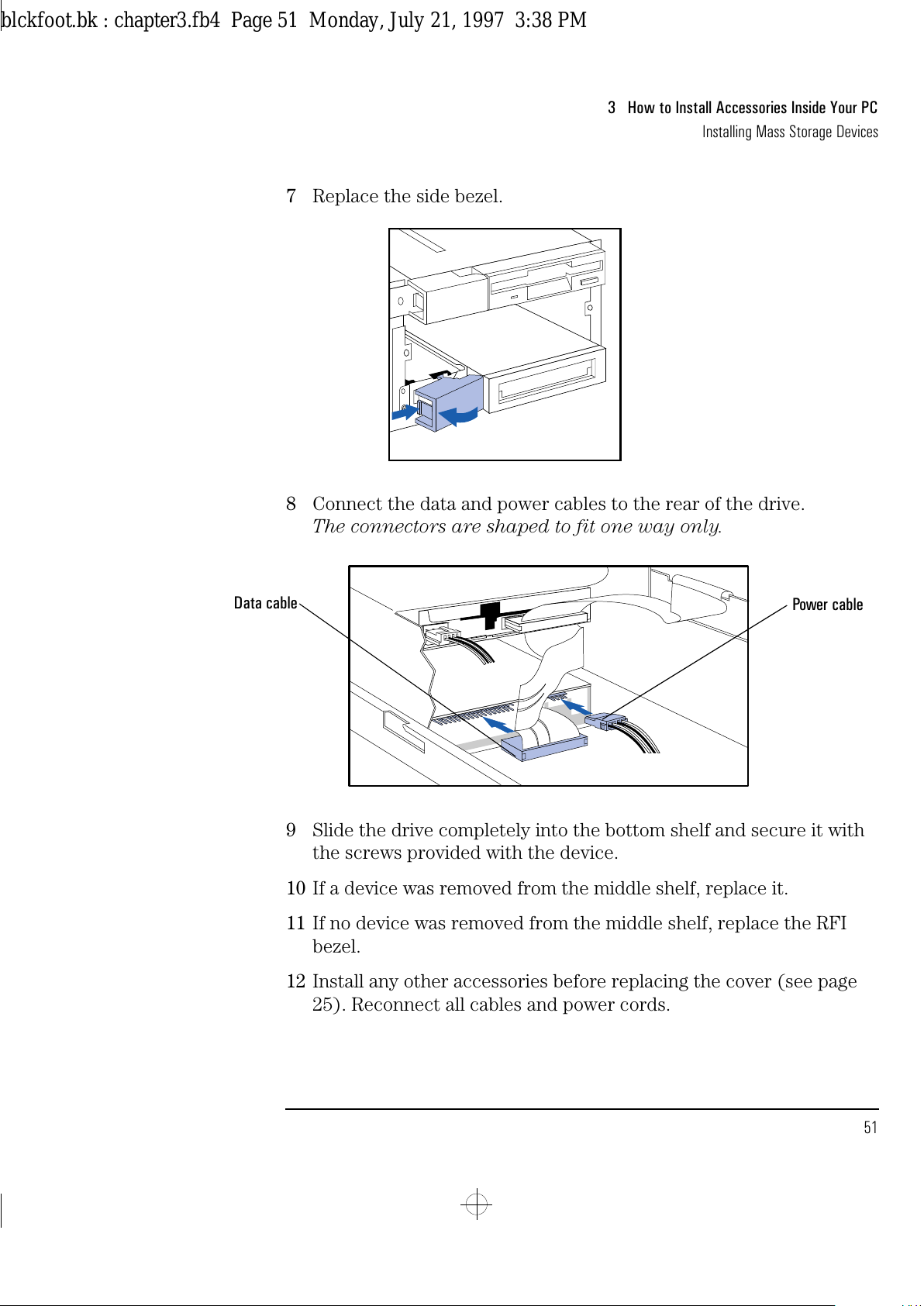
7 Replace the side bezel.
8 Connect the data and power cables to the rear of the drive.
The connectors are shaped to fit one way only.
9 Slide the drive completely into the bottom shelf and secure it with
the screws provided with the device.
10 If a device was removed from the middle shelf, replace it.
11 If no device was removed from the middle shelf, replace the RFI
bezel.
12 Install any other accessories before replacing the cover (see page
25). Reconnect all cables and power cords.
Power cable
Data cable
blckfoot.bk : chapter3.fb4 Page 51 Monday, July 21, 1997 3:38 PM
Page 64
3 How to Install Accessories Inside Your PC
Installing Mass Storage Devices
52 English
Completing the Installation of an IDE Drive
After installing an IDE drive you will need to run the SETUP program
to confirm that the drive has been detected by the PC.
When an Additional IDE
Drive is Installed
1
Switch on the PC.
2
When
<Setup=F2>
appears, press to run the SETUP program.
3
In the
Hard Disk Drives
section, check that the details for
Drive 2
have been correctly detected by the SETUP program.
4
Press to save and exit SETUP.
Refer to the operating system documentation for information on
formatting a drive and installing the operating system.
When the Bootable IDE
Drive is Replaced
1
Switch on the PC.
2
An error message will appear during the Power-On-Self-Test. When
prompted, press to run the SETUP program.
3
In the
Hard Disk Drives
section, check that the details for
Drive 1
have been correctly detected by the SETUP program.
4
Press to save and exit SETUP.
Refer to the operating system documentation for information on
formatting a drive and installing the operating system.
NOTE If an IDE drive is removed, an error message will appear during the
Power-On-Self-Test. You must run the SETUP program and select
None or SCSI
for the missing drive to correct the error.
blckfoot.bk : chapter3.fb4 Page 52 Monday, July 21, 1997 3:38 PM
Page 65
English 53
3 How to Install Accessories Inside Your PC
Installing Mass Storage Devices
When an IDE Drive is
Not Detected by the
SETUP Program
If you have installed an IDE hard disk drive and SETUP has not detected
it, you must enter the details in the SETUP program manually. This
information is supplied by the manufacturer of the hard disk.
1 Switch on the PC.
2 When
<Setup=F2>
appears, press to run the SETUP program.
3 In the
Hard Disk Drives
section, highlight the
Drive 1
—primary
(rear drive)—or
Drive 2
—secondary (front drive)—field, and
change it to
Custom
.
4 Highlight each drive parameter field you want to change.
Press or to change the value, or type in the new value
supplied with the drive. To enter the value -1, type
0
and press .
5 Press to save and exit SETUP.
Refer to the operating system documentation for information on
formatting a drive and installing the operating system.
blckfoot.bk : chapter3.fb4 Page 53 Monday, July 21, 1997 3:38 PM
Page 66
3 How to Install Accessories Inside Your PC
Installing an Upgrade Processor
54 English
Installing an Upgrade Processor
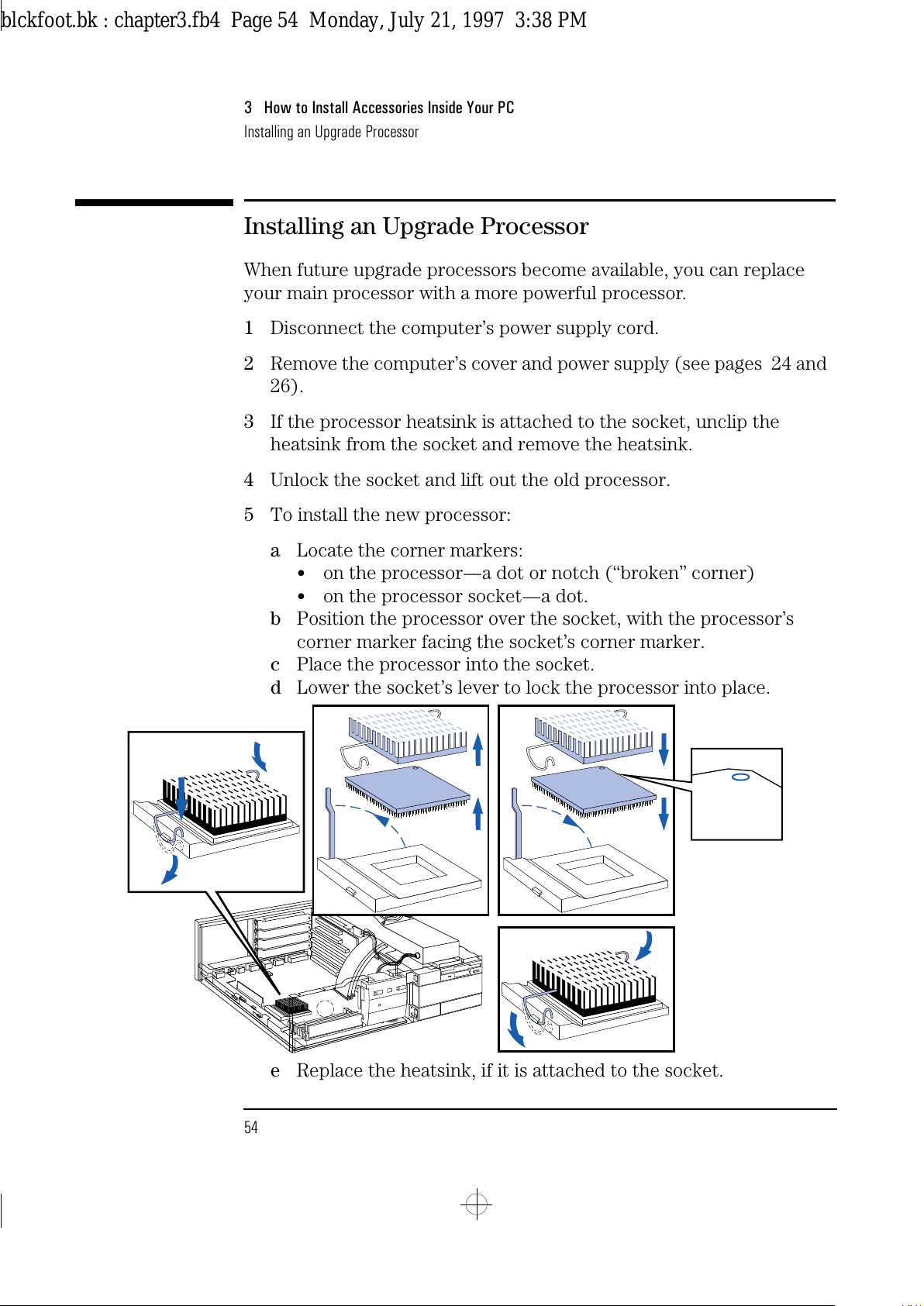
When future upgrade processors become available, you can replace
your main processor with a more powerful processor.
1
Disconnect the computer’s power supply cord.
2
Remove the computer’s cover and power supply (see pages 24 and
26).
3
If the processor heatsink is attached to the socket, unclip the
heatsink from the socket and remove the heatsink.
4
Unlock the socket and lift out the old processor.
5
To install the new processor:
a
Locate the corner markers:
•
on the processor—a dot or notch (“broken” corner)
•
on the processor socket—a dot.
b
Position the processor over the socket, with the processor’s
corner marker facing the socket’s corner marker.
c
Place the processor into the socket.
d
Lower the socket’s lever to lock the processor into place.
e
Replace the heatsink, if it is attached to the socket.
blckfoot.bk : chapter3.fb4 Page 54 Monday, July 21, 1997 3:38 PM
Page 67
English 55
3 How to Install Accessories Inside Your PC
Installing an Upgrade Processor
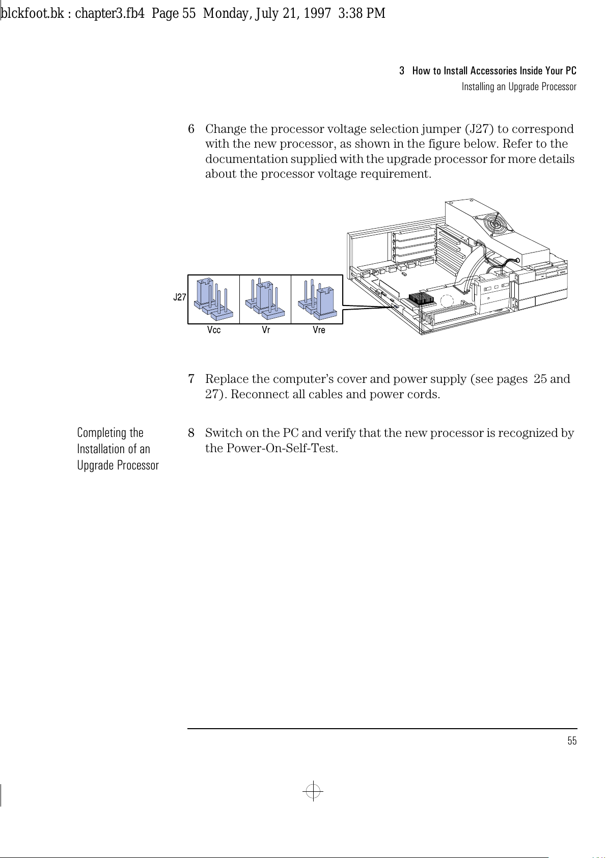
6 Change the processor voltage selection jumper (J27) to correspond
with the new processor, as shown in the figure below. Refer to the
documentation supplied with the upgrade processor for more details
about the processor voltage requirement.
7 Replace the computer’s cover and power supply (see pages 25 and
27). Reconnect all cables and power cords.
Completing the
Installation of an
Upgrade Processor
8 Switch on the PC and verify that the new processor is recognized by
the Power-On-Self-Test.
blckfoot.bk : chapter3.fb4 Page 55 Monday, July 21, 1997 3:38 PM
Page 68
3 How to Install Accessories Inside Your PC
Installing the Security Bracket
56 English
Installing the Security Bracket
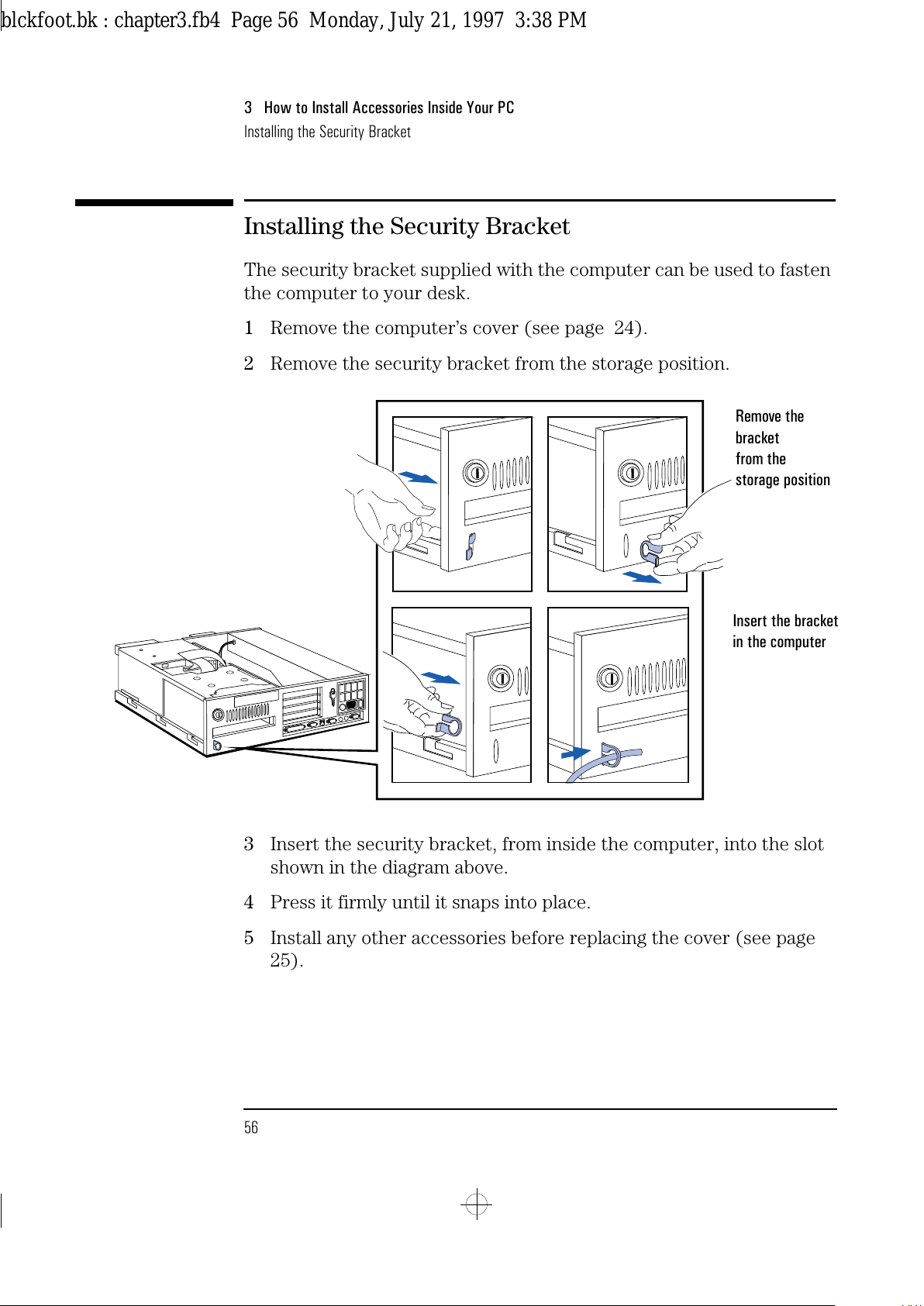
The security bracket supplied with the computer can be used to fasten
the computer to your desk.
1
Remove the computer’s cover (see page 24).
2
Remove the security bracket from the storage position.
3
Insert the security bracket, from inside the computer, into the slot
shown in the diagram above.
4
Press it firmly until it snaps into place.
5
Install any other accessories before replacing the cover (see page
25).
Remove the
bracket
from the
storage position
Insert the bracket
in the computer
blckfoot.bk : chapter3.fb4 Page 56 Monday, July 21, 1997 3:38 PM
Page 69
4
Troubleshooting Your PC and
Using the SETUP Program
This chapter can help you solve problems that you may encounter
when using your PC and describes how to use the HP SETUP program.
blckfoot.bk : chapter4.fb4 Page 57 Monday, July 21, 1997 3:38 PM
Page 70
4 Troubleshooting Your PC and Using the SETUP Program
Solving Problems
58 English
Solving Problems
If you have a problem with your PC, search the list below for the
problem description which most closely matches it. Then turn to the
page indicated for guidance.
If Your PC Does Not
Start
❒
If nothing appears on your display, turn to page 61.
❒
If an error message appears:
•
If a System ROM message appears, turn to page 62.
•
If a Power-On-Self-Test error appears, turn to page 63.
•
If a Power-On-Self-Test error prevents your PC from starting,
turn to page 64.
•
If a BIOS message prevents your PC from starting, turn to page
65.
•
If an Operating System message prevents your PC from starting,
turn to page 66.
If Your PC Has a
Hardware Problem
❒
If your display does not work, turn to page 67.
•
If your display is blurred or unreadable, turn to page 68.
•
If you cannot set any video resolution higher than 640 ✕ 480, turn
to page 69.
❒
If your keyboard or mouse does not work, turn to page 70.
❒
If your printer does not work, turn to page 71.
❒
If the flexible disk drive does not work, turn to page 72.
❒
If the hard disk does not work, turn to page 72.
•
If the hard disk activity light does not work, turn to page 73.
❒
If an accessory board does not work, turn to page 73.
blckfoot.bk : chapter4.fb4 Page 58 Monday, July 21, 1997 3:38 PM
Page 71
English 59
4 Troubleshooting Your PC and Using the SETUP Program
Solving Problems
If Your PC Has a
Software Problem
❒
If you have forgotten your passwords, turn to page 74.
❒
If you can’t start the SETUP program, turn to page 75.
❒
If your application software does not work, turn to page 75.
❒
If power management does not work, turn to page 76.
❒
If the date and time are incorrect, turn to page 76.
If You Cannot Solve the Problem
If you are unable to solve your problem after following the
troubleshooting advice in this chapter, refer to chapter 6 Getting
Support for information on getting help from your HP Reseller or from
your nearest HP Customer Support Center.
WARNING
There is a danger of explosion if the battery is incorrectly
installed. HP recommends that the battery is installed by
trained service personnel.
For your safety, never attempt to recharge, disassemble, or
burn the old battery.
In order to protect the environment, do not dispose of
batteries in the household waste. Please return used batteries
to the shop from which you bought them, or to the dealer from
whom you purchased your PC, or to HP so they can either be
recycled or disposed of in an environmentally sound way.
After removing the old battery, install either a replacement
battery (order 1420-0312) or an external battery (order 1420-
0513).
blckfoot.bk : chapter4.fb4 Page 59 Monday, July 21, 1997 3:38 PM
Page 72
4 Troubleshooting Your PC and Using the SETUP Program
If Your PC Does Not Start
60 English
If Your PC Does Not Start
If Your Display is Blank and There Are No Error Messages
1
Make sure that all cables and power cords are firmly plugged in.
2
Make sure the power outlet is working.
3
Check that the computer and display are turned on. (The power light
should be illuminated.)
4
Check the display’s contrast and brightness settings.
5
If the PC still does not work:
a
Turn off the display, the computer, and all external devices.
b
Unplug all power cords and cables, noting their positions.
c
Remove the cover (refer to page 25).
d
Check that the processor is correctly installed (refer to page 54).
e
Check that the memory modules are correctly installed (refer to
page 28).
f
Check that accessory boards are firmly seated in their slots (refer
to page 32).
g
Verify that any switches and jumpers on the accessory boards are
properly set (refer to the manuals that came with each board).
h
Check that the jumpers and switches on the system board are
properly set (refer to page 90).
i
Replace the cover (refer to page 25).
j
Connect all cables and power cords (refer to pages 4 and 7).
k
Turn on the display and computer.
If your PC still does not start, remove all boards and accessories,
except the hard disk drive. Start the PC. If the PC now works, add the
boards and accessories one at a time to determine which one is causing
the problem.
blckfoot.bk : chapter4.fb4 Page 60 Monday, July 21, 1997 3:38 PM
Page 73
English 61
4 Troubleshooting Your PC and Using the SETUP Program
If Your PC Does Not Start
If an Error Message Appears
If a System ROM Message Appears
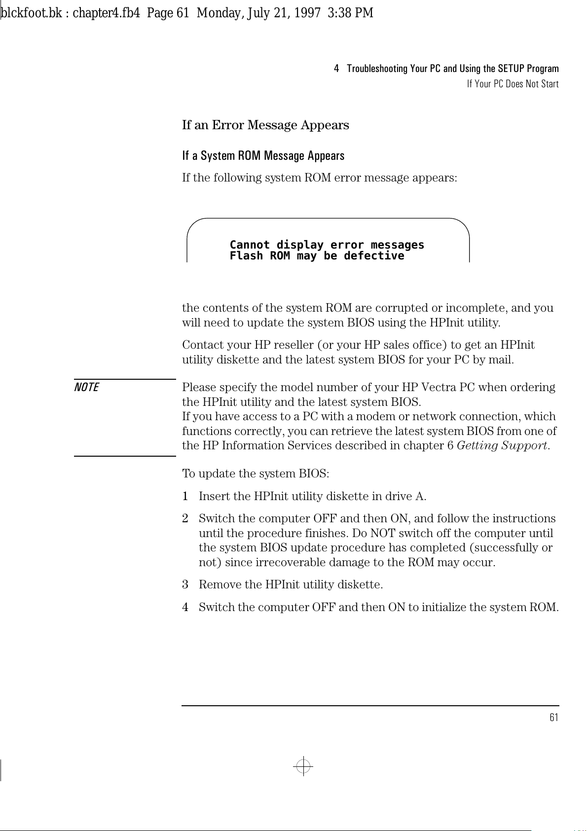
If the following system ROM error message appears:
the contents of the system ROM are corrupted or incomplete, and you
will need to update the system BIOS using the HPInit utility.
Contact your HP reseller (or your HP sales office) to get an HPInit
utility diskette and the latest system BIOS for your PC by mail.
NOTE Please specify the model number of your HP Vectra PC when ordering
the HPInit utility and the latest system BIOS.
If you have access to a PC with a modem or network connection, which
functions correctly, you can retrieve the latest system BIOS from one of
the HP Information Services described in chapter 6 Getting Support.
To update the system BIOS:
1
Insert the HPInit utility diskette in drive A.
2
Switch the computer OFF and then ON, and follow the instructions
until the procedure finishes. Do NOT switch off the computer until
the system BIOS update procedure has completed (successfully or
not) since irrecoverable damage to the ROM may occur.
3
Remove the HPInit utility diskette.
4
Switch the computer OFF and then ON to initialize the system ROM.
Cannot display error messages
Flash ROM may be defective
blckfoot.bk : chapter4.fb4 Page 61 Monday, July 21, 1997 3:38 PM
Page 74
4 Troubleshooting Your PC and Using the SETUP Program
If Your PC Does Not Start
62 English
If a Power-On-Self-Test Error Appears
NOTE You can stop the memory test and jump to the next test by pressing .
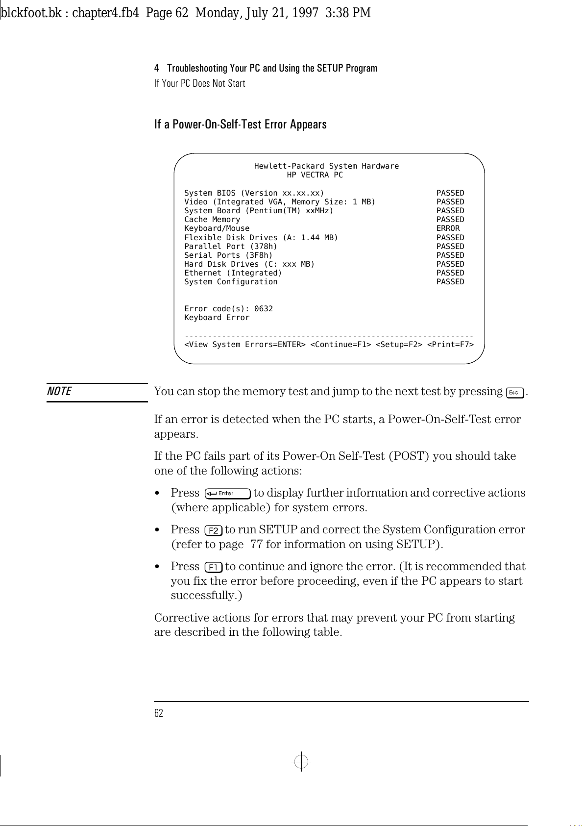
If an error is detected when the PC starts, a Power-On-Self-Test error
appears.
If the PC fails part of its Power-On Self-Test (POST) you should take
one of the following actions:
•
Press to display further information and corrective actions
(where applicable) for system errors.
•
Press to run SETUP and correct the System Configuration error
(refer to page 77 for information on using SETUP).
•
Press to continue and ignore the error. (It is recommended that
you fix the error before proceeding, even if the PC appears to start
successfully.)
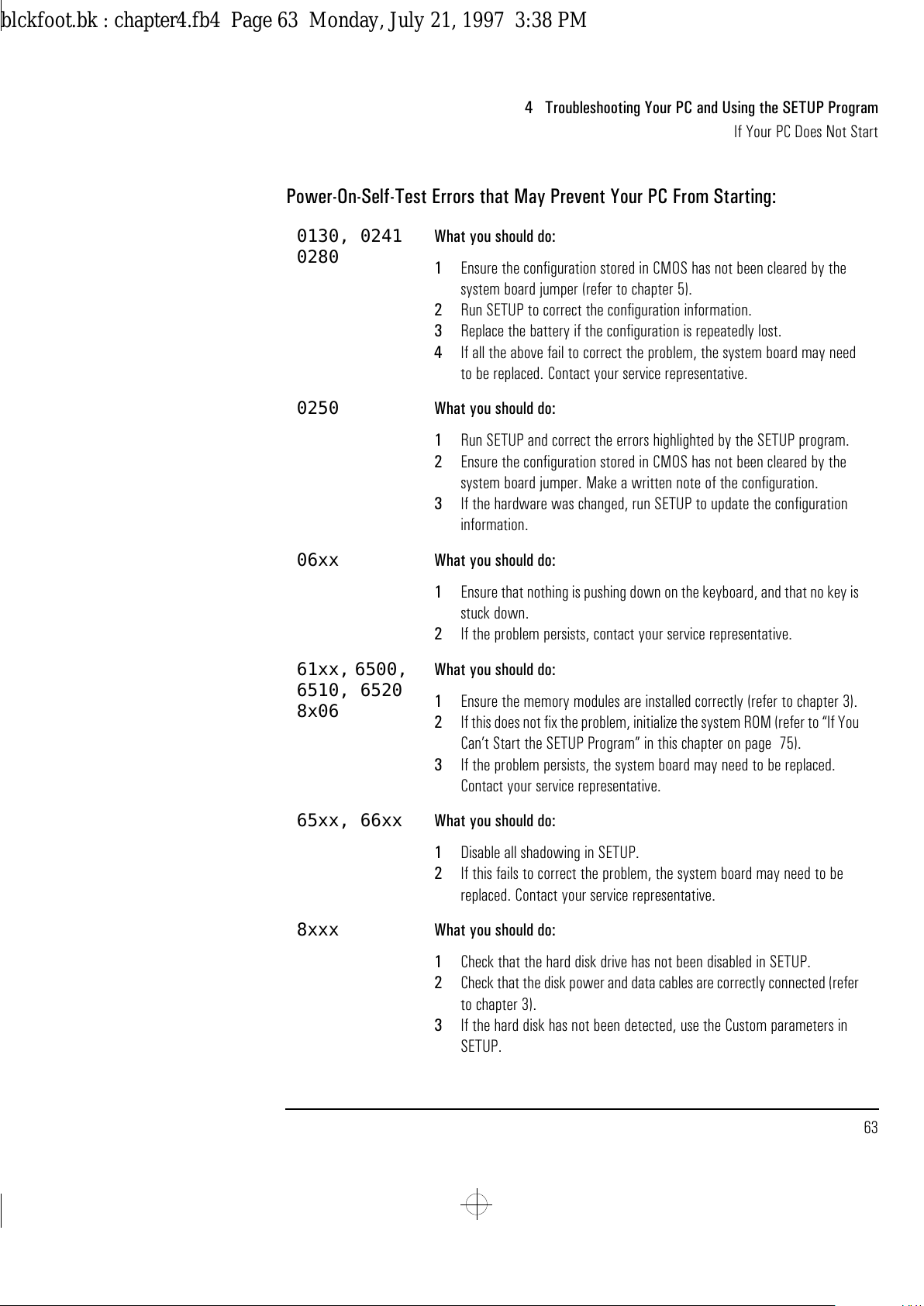
Corrective actions for errors that may prevent your PC from starting
are described in the following table.
Hewlett-Packard System Hardware
HP VECTRA PC
System BIOS (Version xx.xx.xx) PASSED
Video (Integrated VGA, Memory Size: 1 MB) PASSED
System Board (Pentium(TM) xxMHz) PASSED
Cache Memory PASSED
Keyboard/Mouse ERROR
Flexible Disk Drives (A: 1.44 MB) PASSED
Parallel Port (378h) PASSED
Serial Ports (3F8h) PASSED
Hard Disk Drives (C: xxx MB) PASSED
Ethernet (Integrated) PASSED
System Configuration PASSED
Error code(s): 0632
Keyboard Error
--------------------------------------------------------------
<View System Errors=ENTER> <Continue=F1> <Setup=F2> <Print=F7>
blckfoot.bk : chapter4.fb4 Page 62 Monday, July 21, 1997 3:38 PM
Page 75
English 63
4 Troubleshooting Your PC and Using the SETUP Program
If Your PC Does Not Start
Power-On-Self-Test Errors that May Prevent Your PC From Starting:
0130, 0241
0280
What you should do:
1 Ensure the configuration stored in CMOS has not been cleared by the
system board jumper (refer to chapter 5).
2 Run SETUP to correct the configuration information.
3 Replace the battery if the configuration is repeatedly lost.
4 If all the above fail to correct the problem, the system board may need
to be replaced. Contact your service representative.
0250 What you should do:
1 Run SETUP and correct the errors highlighted by the SETUP program.
2 Ensure the configuration stored in CMOS has not been cleared by the
system board jumper. Make a written note of the configuration.
3 If the hardware was changed, run SETUP to update the configuration
information.
06xx What you should do:
1 Ensure that nothing is pushing down on the keyboard, and that no key is
stuck down.
2 If the problem persists, contact your service representative.
61xx, 6500,
6510, 6520
8x06
What you should do:
1 Ensure the memory modules are installed correctly (refer to chapter 3).
2 If this does not fix the problem, initialize the system ROM (refer to “If You
Can’t Start the SETUP Program” in this chapter on page 75).
3 If the problem persists, the system board may need to be replaced.
Contact your service representative.
65xx, 66xx What you should do:
1 Disable all shadowing in SETUP.
2 If this fails to correct the problem, the system board may need to be
replaced. Contact your service representative.
8xxx What you should do:
1 Check that the hard disk drive has not been disabled in SETUP.
2 Check that the disk power and data cables are correctly connected (refer
to chapter 3).
3 If the hard disk has not been detected, use the Custom parameters in
SETUP.
blckfoot.bk : chapter4.fb4 Page 63 Monday, July 21, 1997 3:38 PM
Page 76
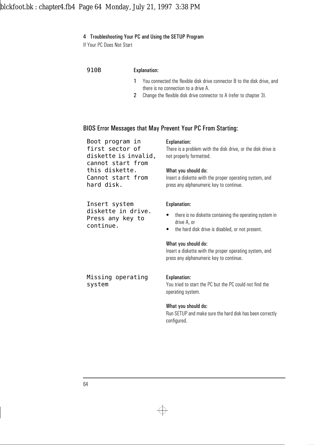
4 Troubleshooting Your PC and Using the SETUP Program
If Your PC Does Not Start
64 English
BIOS Error Messages that May Prevent Your PC From Starting:
910B Explanation:
1 You connected the flexible disk drive connector B to the disk drive, and
there is no connection to a drive A.
2 Change the flexible disk drive connector to A (refer to chapter 3).
Boot program in
first sector of
diskette is invalid,
cannot start from
this diskette.
Cannot start from
hard disk.
Explanation:
There is a problem with the disk drive, or the disk drive is
not properly formatted.
What you should do:
Insert a diskette with the proper operating system, and
press any alphanumeric key to continue.
Insert system
diskette in drive.
Press any key to
continue.
Explanation:
•
there is no diskette containing the operating system in
drive A, or
•
the hard disk drive is disabled, or not present.
What you should do:
Insert a diskette with the proper operating system, and
press any alphanumeric key to continue.
Missing operating
system
Explanation:
You tried to start the PC but the PC could not find the
operating system.
What you should do:
Run SETUP and make sure the hard disk has been correctly
configured
.
blckfoot.bk : chapter4.fb4 Page 64 Monday, July 21, 1997 3:38 PM
Page 77
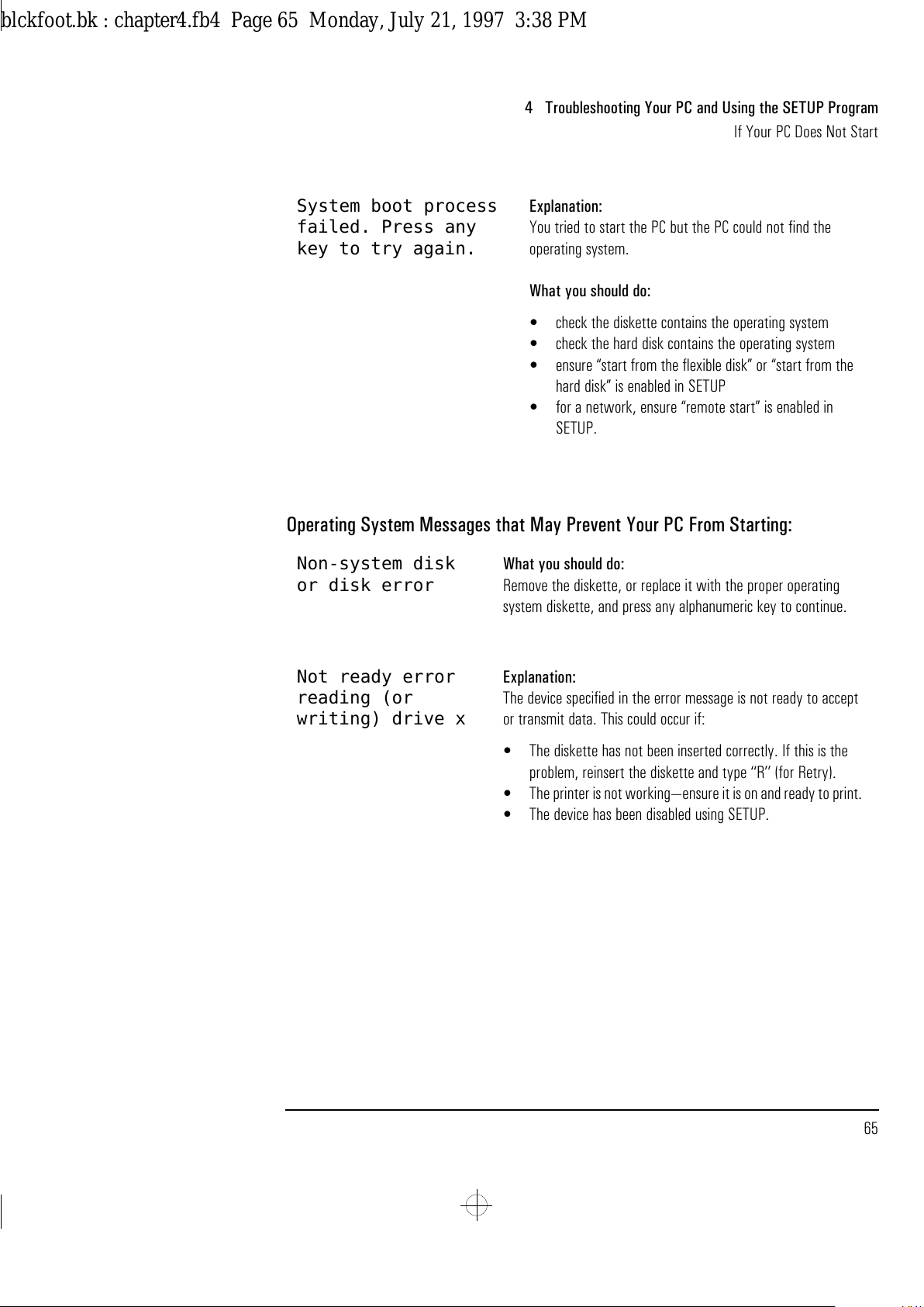
English 65
4 Troubleshooting Your PC and Using the SETUP Program
If Your PC Does Not Start
Operating System Messages that May Prevent Your PC From Starting:
System boot process
failed. Press any
key to try again.
Explanation:
You tried to start the PC but the PC could not find the
operating system.
What you should do:
•
check the diskette contains the operating system
•
check the hard disk contains the operating system
•
ensure “start from the flexible disk” or “start from the
hard disk” is enabled in SETUP
•
for a network, ensure “remote start” is enabled in
SETUP.
Non-system disk
or disk error
What you should do:
Remove the diskette, or replace it with the proper operating
system diskette, and press any alphanumeric key to continue.
Not ready error
reading (or
writing) drive x
Explanation:
The device specified in the error message is not ready to accept
or transmit data. This could occur if:
•
The diskette has not been inserted correctly. If this is the
problem, reinsert the diskette and type ‘‘R’’ (for Retry).
•
The printer is not working—ensure it is on and ready to print.
•
The device has been disabled using SETUP.
blckfoot.bk : chapter4.fb4 Page 65 Monday, July 21, 1997 3:38 PM
Page 78
4 Troubleshooting Your PC and Using the SETUP Program
If Your PC Has a Hardware Problem
66 English
If Your PC Has a Hardware Problem
This section describes what to do if you have problems with your
display, disk drives, printer, accessory board, keyboard, or mouse.
If Your Display Does Not Work
If nothing is displayed on the screen, but the PC starts and the
keyboard, disk drives, and other peripheral devices seem to operate
properly:
1
Check that the brightness and contrast controls are properly set.
2
Make sure that the display is plugged in and switched ON.
3
Ensure that the display video cable is correctly connected.
4
Switch off the display, and unplug it from the power outlet. Examine
the video cable pins to see if they are bent. If they are, carefully
straighten them.
5
Make sure that an accessory board does not use the same I/O address
as the integrated video interface (03B0h to 03DFh). Refer to the
documentation supplied with the accessory for more information
about the I/O addresses used by it.
If the display image is not aligned with the screen (usually when you
change resolutions), use the display’s controls to center the image.
Refer to the display manual for instructions.
If the screens generated by the applications do not appear correct,
check the application’s manual to find out which video standard is
required. Also check your display manual to find out which refresh rate
is required. Use SETUP or the HP User Tools to select the correct
refresh rate.
blckfoot.bk : chapter4.fb4 Page 66 Monday, July 21, 1997 3:38 PM
Page 79
English 67
4 Troubleshooting Your PC and Using the SETUP Program
If Your PC Has a Hardware Problem
If the display works correctly during the Power-On-Self-Test (POST),
but goes blank when Windows starts:
•
Restart the PC and check that the amount of video memory detected
by the POST is correct. If you have installed extra video memory and
only 1 MB is detected, check that the video memory modules are
installed correctly (see page 30).
•
If the video memory is correctly detected by the POST, follow the
instructions below to correct the problem.
If Your Display is Blurred or Unreadable
If you select the wrong display in the HP User Tools menu, the display
screen may become blurred or unreadable. To correct this problem:
1 Restart the PC — either switch the PC off then on, or press
and . The PC will perform its Power-On-Self-Test
(POST).
2 When the POST is finished, press to bypass the startup files and
display the MS-DOS prompt (
C:\
).
3 Type
CD C:\WINDOWS
.
4Type
SETUP
.
5Press the up-arrow key to select the
Display
line, and press
.
6 Select the
VGA
line, and press .
7 Press again to accept the configuration.
8 Press and to restart the PC.
9 If necessary, type
WIN
to restart Windows.
10 When Windows starts, select the correct display with the HP User
Tools. Refer to chapter 2 for more information about the HP User
Tools.
Delete
Delete
blckfoot.bk : chapter4.fb4 Page 67 Monday, July 21, 1997 3:38 PM
Page 80
4 Troubleshooting Your PC and Using the SETUP Program
If Your PC Has a Hardware Problem
68 English
If You Cannot Use Any Video Resolution Higher Than 640 ✕ 480
If you cannot select a video resolution higher than 640 ✕ 480, you
should clear the contents of the CMOS RAM.
To clear the configuration:
1 Switch off the PC and remove the cover (refer to chapter 3).
2 Set the system board switch 3 (CONFG) on the switch block to ON
to clear the configuration (refer to page 91 for the switch location).
3 Switch on the PC to erase the memory.
4 Check that error codes
0240
and
0130
are displayed, and wait until
the PC has started.
5 Switch off the PC.
6 Set the system board switch 3 (CONFG) on the switch block to OFF
to re-enable the configuration.
7 Replace the cover (refer to chapter 3).
8 Switch on the PC and run SETUP by pressing when
<Setup=F2>
appears. (Error code
0130
will appear when the PC
starts.)
9 Press to save the configuration and exit from SETUP.
blckfoot.bk : chapter4.fb4 Page 68 Monday, July 21, 1997 3:38 PM
Page 81
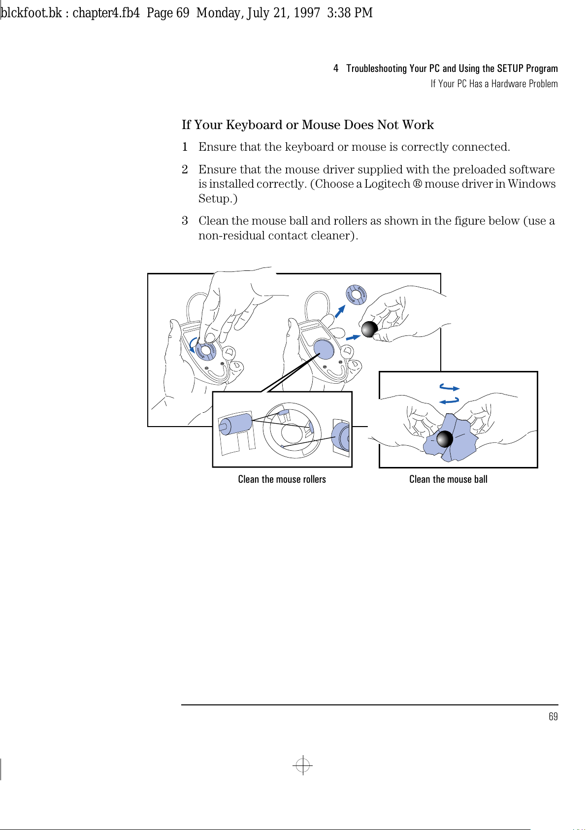
English 69
4 Troubleshooting Your PC and Using the SETUP Program
If Your PC Has a Hardware Problem
If Your Keyboard or Mouse Does Not Work
1
Ensure that the keyboard or mouse is correctly connected.
2
Ensure that the mouse driver supplied with the preloaded software
is installed correctly. (Choose a Logitech ® mouse driver in Windows
Setup.)
3
Clean the mouse ball and rollers as shown in the figure below (use a
non-residual contact cleaner).
Clean the mouse ballClean the mouse rollers
blckfoot.bk : chapter4.fb4 Page 69 Monday, July 21, 1997 3:38 PM
Page 82
4 Troubleshooting Your PC and Using the SETUP Program
If Your PC Has a Hardware Problem
70 English
If Your Printer Does Not Work
1
Verify that the power cord is plugged into the power outlet and the
printer.
2
Make sure the printer’s power switch is ON.
3
Check that the printer is on-line.
4
Examine the paper feed mechanism for a paper jam.
5
Verify that you have the correct cable for the printer. Make sure that
it is securely connected to the correct connector (port) on the PC
and printer.
6
Make sure that the printer is configured correctly for the PC and for
the application.
a
Ensure that the PC’s port has been correctly configured using
SETUP.
b
Make sure the printer is correctly set up in Windows.
NOTE If you are asked to insert a diskette when installing a printer, type
C:\WINDOWS\OPTIONS
and press . All of the Windows printer
drivers are located in this subdirectory.
c
Ensure the application program’s “print” menu has been correctly
set up. (Refer to the manual supplied with the application
software.)
7
Check that the PC’s port is working properly by running another
peripheral connected to the port.
8
If you receive an error message, refer to the printer’s manual for
help.
blckfoot.bk : chapter4.fb4 Page 70 Monday, July 21, 1997 3:38 PM
Page 83
English 71
4 Troubleshooting Your PC and Using the SETUP Program
If Your PC Has a Hardware Problem
If the Flexible Disk Drive Does Not Work
1
Ensure you are using a formatted diskette and it is inserted
correctly.
2
Check you are using a diskette that is the right density.
3
Check that the flexible disk drive has not been disabled in SETUP
(refer to page 77). There are three options in the
Security
Features
section of SETUP which may be used to disable or enable:
•
the flexible disk drives
•
start from flexible disk
•
writing to flexible disks.
4
Check that the disk power and data cables are correctly connected
(refer to chapter 3).
5
Clean the flexible disk drive using a “wet-cleaning diskette kit”.
If the Hard Disk Does Not Work
1
Check that the hard disk drive has not been disabled in SETUP (refer
to page 77). There are two options in the
Security Features
section of SETUP which may be used to disable or enable:
•
the hard disk drives
•
start from hard disk.
2
Check that the disk power and data cables are correctly connected
(refer to chapter 3).
3
Check that power management has been correctly configured.
4
If the hard disk has not been detected, use the Custom parameters
in SETUP.
blckfoot.bk : chapter4.fb4 Page 71 Monday, July 21, 1997 3:38 PM
Page 84
4 Troubleshooting Your PC and Using the SETUP Program
If Your PC Has a Hardware Problem
72 English
If the Hard Disk Activity Light Does Not Work
If the hard disk activity light does not flicker when the PC is accessing
the hard disk drive:
1 Check that the control panel connector is firmly attached to the
system board.
2 Check that the disk power and data cables are correctly connected
(refer to chapter 3).
3 If you are using a hard disk drive with a controller board (a SCSI hard
disk, for example), the activity light does not flicker when the PC is
accessing the hard disk drive.
If an Accessory Board Does Not Work
Perform the following checks:
1 Ensure the board has been firmly installed in the accessory board
slot (refer to chapter 3).
2 Check that the accessory board has been correctly configured with
the ISA Configuration Utility.
3 Ensure the board is not using memory, I/O addresses, an IRQ, or
DMA also used by the PC. Refer to the board’s manual for details. For
information on the current usage of IRQs by the PC, at the MS-DOS
prompt type MSD and press .
4 Check that the PC has been configured correctly in SETUP.
5 If the problem persists, contact your service representative.
blckfoot.bk : chapter4.fb4 Page 72 Monday, July 21, 1997 3:38 PM
Page 85
English 73
4 Troubleshooting Your PC and Using the SETUP Program
If Your PC Has a Software Problem
If Your PC Has a Software Problem
If You Have Forgotten Your Password
❒
If you forget the User Password and the System Administrator
Password is set and known:
1
Restart the PC. If the keyboard is locked, unplug the power cord
and plug it in again.
2
Wait for the message
<F2=Setup>
.
3
Press to start SETUP.
4
Type the System Administrator Password to enter SETUP.
5
Highlight the
User Password
field and set a new User Password.
6
Press to save the new User Password and exit SETUP.
❒
If you forget both the User Password and the System Administrator
Password:
1
Switch off the PC.
2
Remove the computer’s cover (refer to chapter 3).
3
Set switch 4 (PSWRD) on the system board switch block to ON
(refer to chapter 5 for the switch location).
4
Switch on the PC and allow it to complete its startup routine.
5
Switch off the computer.
6
Reset switch 4 (PSWRD) to OFF.
7
Replace the computer’s cover (refer to chapter 3).
8
Switch on the PC and allow it to complete its startup routine.
9
After the Power-On Self-Test has completed, press when
prompted to use SETUP.
10
Set new User and System Administrator Passwords.
11
Press to save the new passwords and exit SETUP.
blckfoot.bk : chapter4.fb4 Page 73 Monday, July 21, 1997 3:38 PM
Page 86
4 Troubleshooting Your PC and Using the SETUP Program
If Your PC Has a Software Problem
74 English
If You Can’t Start the SETUP Program
This may happen if the copy of the PC’s configuration stored in
memory is corrupted. You will need to erase this bad configuration.
To clear the configuration:
1
Switch off the PC and remove the cover (refer to chapter 3).
2
Set the system board switch 3 (CONFG) on the switch block to ON
to clear the configuration (refer to page 91 for the switch location).
3
Switch on the PC to erase the memory.
4
Check that error codes
0240
and
0130
are displayed, and wait until
the PC has started.
5
Switch off the PC.
6
Set the system board switch 3 (CONFG) on the switch block to OFF
to re-enable the configuration.
7
Replace the cover (refer to chapter 3).
8
Switch on the PC and run SETUP by pressing when
<Setup=F2>
appears. (Error code
0130
will appear when the PC
starts.)
9
Press to save the configuration and exit from SETUP.
If Your Application Software Does Not Work
If the PC reports the system is OK but some software won’t run, and
the indicator light over the power switch is illuminated:
1
Check to see if the
AUTOEXEC.BAT
file is present with the correct
settings. Refer to the operating system and application software
manuals.
2
If Windows does not run properly, refer to the Windows manual for
guidance.
blckfoot.bk : chapter4.fb4 Page 74 Monday, July 21, 1997 3:38 PM
Page 87
English 75
4 Troubleshooting Your PC and Using the SETUP Program
If Your PC Has a Software Problem
If Power Management Does Not Work
Power Management in
Windows
Check that the Sleep icon appears in the StartUp Windows group.
If it is absent, click on the File menu in the Program Manager and select
the New option to install
SLEEP.EXE
from the
C:\WINDOWS
directory in
the StartUp group.
Check that Power Management is enabled using the Power icon in
the Windows Control Panel:
1
Double-click on the Power icon in the Windows Control Panel.
2
Check that
Advanced
is selected in the Power dialog box.
If the Power icon does not appear in the Windows Control Panel:
1
Exit from Windows.
2
At the MS-DOS prompt, change to the
C:\WINDOWS
directory.
3
Type
SETUP
to run Windows Setup and set the
Computer
field to
MS-DOS with APM
. Follow the instructions displayed by the
Setup program to return to the MS-DOS prompt.
Power Management in
DOS
Use a text editor to check that
DEVICE=C:\DOS\POWER.EXE ADV:MAX
is present in the CONFIG.SYS file.
If the Date and Time Are Incorrect
The date and time can be incorrect for the following reasons:
•
the time has changed for the seasons
•
the PC has been unplugged from the power too long, and the battery
is discharged.
To change the date and time use the HP User Tools program. Refer to
chapter 2 for more information about the HP User Tools. If you do not
have the HP User Tools program installed, you can use the SETUP
program to change the date and time.
blckfoot.bk : chapter4.fb4 Page 75 Monday, July 21, 1997 3:38 PM
Page 88
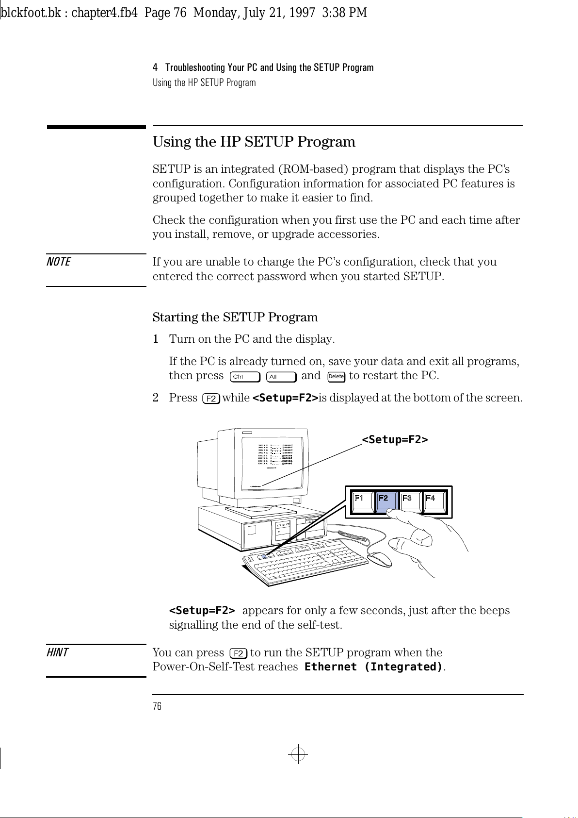
4 Troubleshooting Your PC and Using the SETUP Program
Using the HP SETUP Program
76 English
Using the HP SETUP Program
SETUP is an integrated (ROM-based) program that displays the PC’s
configuration. Configuration information for associated PC features is
grouped together to make it easier to find.
Check the configuration when you first use the PC and each time after
you install, remove, or upgrade accessories.
NOTE If you are unable to change the PC’s configuration, check that you
entered the correct password when you started SETUP.
Starting the SETUP Program
1
Turn on the PC and the display.
If the PC is already turned on, save your data and exit all programs,
then press and to restart the PC.
2
Press while
<Setup=F2>
is displayed at the bottom of the screen.
<Setup=F2> appears for only a few seconds, just after the beeps
signalling the end of the self-test.
HINT You can press to run the SETUP program when the
Power-On-Self-Test reaches
Ethernet (Integrated)
.
Delete
<Setup=F2>
blckfoot.bk : chapter4.fb4 Page 76 Monday, July 21, 1997 3:38 PM
Page 89
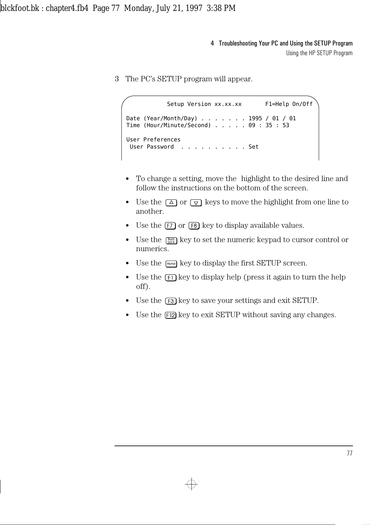
English 77
4 Troubleshooting Your PC and Using the SETUP Program
Using the HP SETUP Program
3 The PC’s SETUP program will appear.
•
To change a setting, move the highlight to the desired line and
follow the instructions on the bottom of the screen.
•
Use the or keys to move the highlight from one line to
another.
•
Use the or key to display available values.
•
Use the key to set the numeric keypad to cursor control or
numerics.
•
Use the key to display the first SETUP screen.
•
Use the key to display help (press it again to turn the help
off).
•
Use the key to save your settings and exit SETUP.
•
Use the key to exit SETUP without saving any changes.
Setup Version xx.xx.xx F1=Help On/Off
Date (Year/Month/Day) . . . . . . . 1995 / 01 / 01
Time (Hour/Minute/Second) . . . . . 09 : 35 : 53
User Preferences
User Password . . . . . . . . . . Set
Num
Lock
Home
blckfoot.bk : chapter4.fb4 Page 77 Monday, July 21, 1997 3:38 PM
Page 90
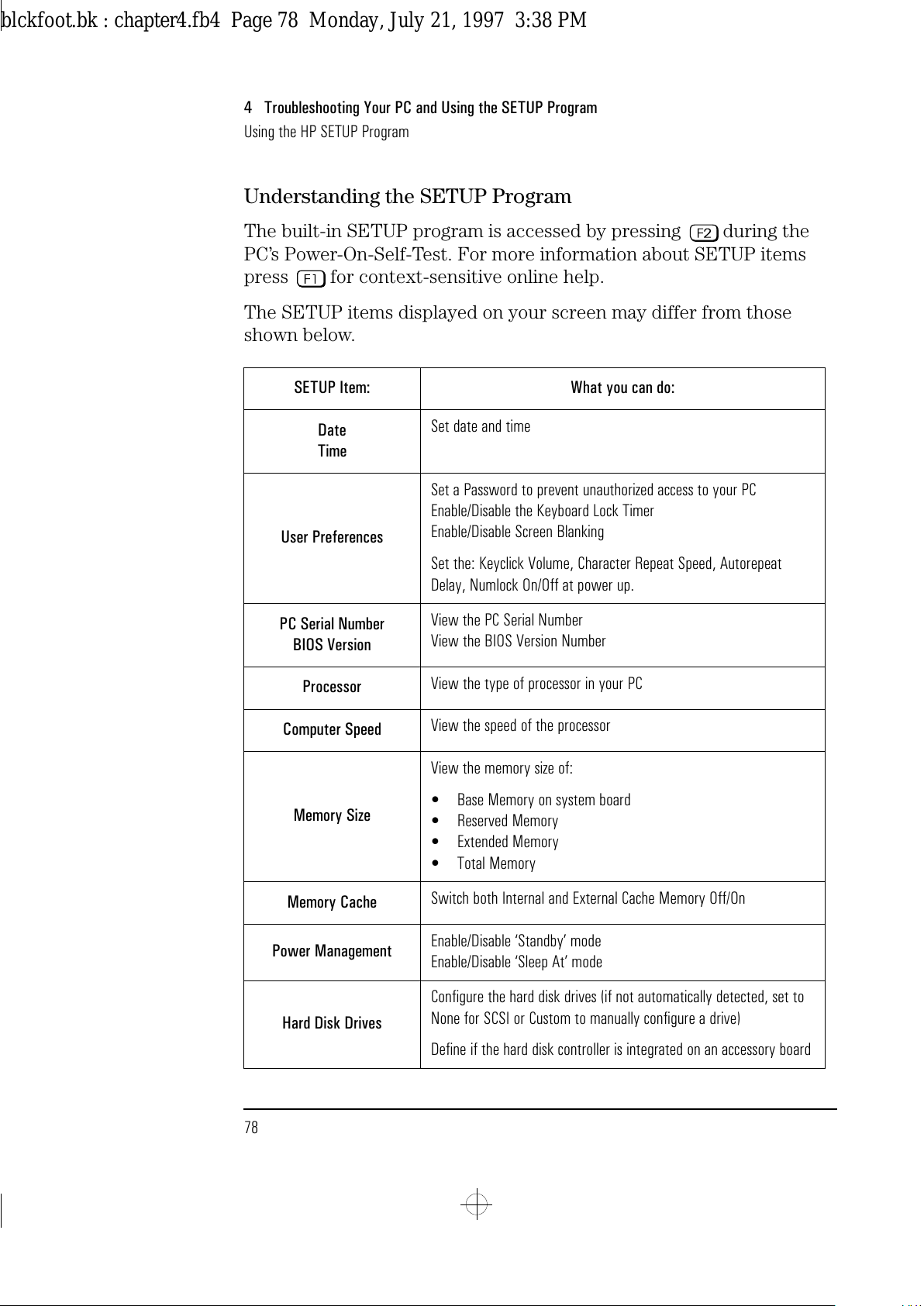
4 Troubleshooting Your PC and Using the SETUP Program
Using the HP SETUP Program
78 English
Understanding the SETUP Program
The built-in SETUP program is accessed by pressing during the
PC’s Power-On-Self-Test. For more information about SETUP items
press for context-sensitive online help.
The SETUP items displayed on your screen may differ from those
shown below.
SETUP Item: What you can do:
Date
Time
Set date and time
User Preferences
Set a Password to prevent unauthorized access to your PC
Enable/Disable the Keyboard Lock Timer
Enable/Disable Screen Blanking
Set the: Keyclick Volume, Character Repeat Speed, Autorepeat
Delay, Numlock On/Off at power up.
PC Serial Number
BIOS Version
View the PC Serial Number
View the BIOS Version Number
Processor
View the type of processor in your PC
Computer Speed
View the speed of the processor
Memory Size
View the memory size of:
•
Base Memory on system board
•
Reserved Memory
•
Extended Memory
•
Total Memory
Memory Cache
Switch both Internal and External Cache Memory Off/On
Power Management
Enable/Disable ‘Standby’ mode
Enable/Disable ‘Sleep At’ mode
Hard Disk Drives
Configure the hard disk drives (if not automatically detected, set to
None for SCSI or Custom to manually configure a drive)
Define if the hard disk controller is integrated on an accessory board
blckfoot.bk : chapter4.fb4 Page 78 Monday, July 21, 1997 3:38 PM
Page 91
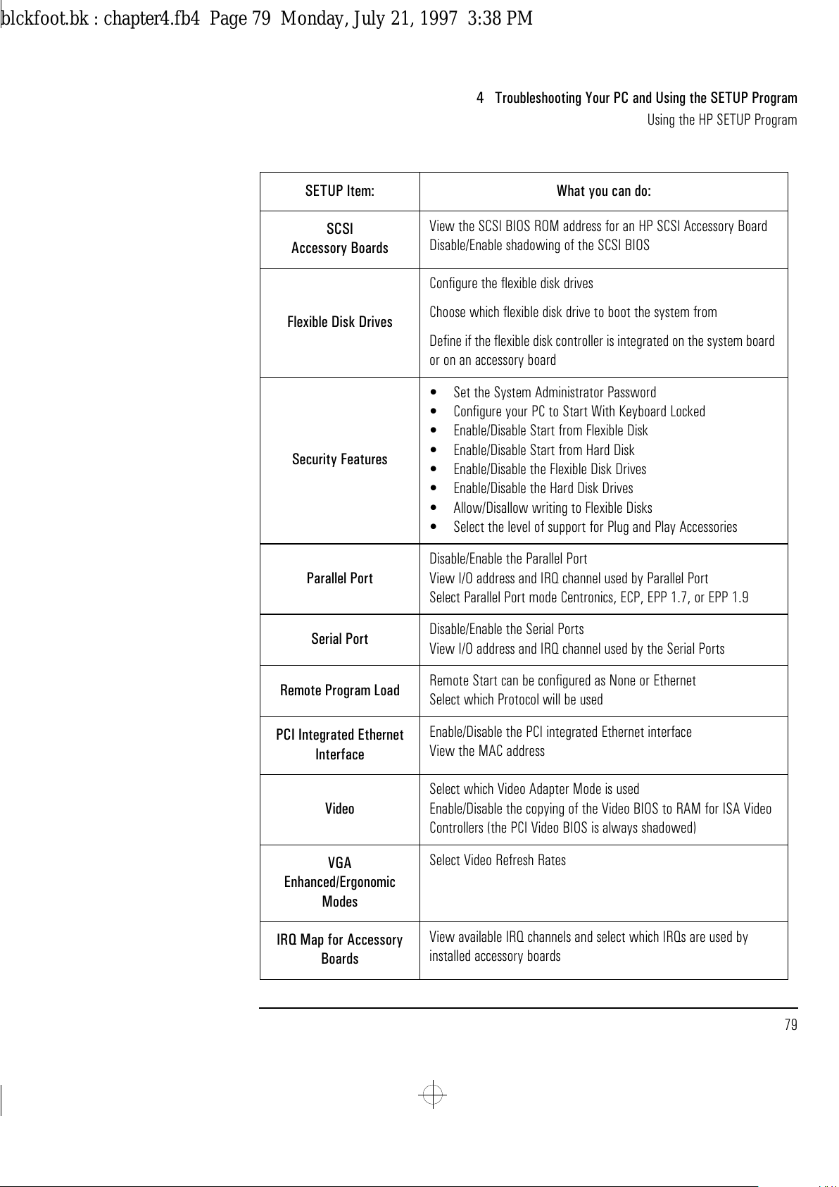
English 79
4 Troubleshooting Your PC and Using the SETUP Program
Using the HP SETUP Program
SCSI
Accessory Boards
View the SCSI BIOS ROM address for an HP SCSI Accessory Board
Disable/Enable shadowing of the SCSI BIOS
Flexible Disk Drives
Configure the flexible disk drives
Choose which flexible disk drive to boot the system from
Define if the flexible disk controller is integrated on the system board
or on an accessory board
Security Features
•
Set the System Administrator Password
•
Configure your PC to Start With Keyboard Locked
•
Enable/Disable Start from Flexible Disk
•
Enable/Disable Start from Hard Disk
•
Enable/Disable the Flexible Disk Drives
•
Enable/Disable the Hard Disk Drives
•
Allow/Disallow writing to Flexible Disks
•
Select the level of support for Plug and Play Accessories
Parallel Port
Disable/Enable the Parallel Port
View I/O address and IRQ channel used by Parallel Port
Select Parallel Port mode Centronics, ECP, EPP 1.7, or EPP 1.9
Serial Port
Disable/Enable the Serial Ports
View I/O address and IRQ channel used by the Serial Ports
Remote Program Load
Remote Start can be configured as None or Ethernet
Select which Protocol will be used
PCI Integrated Ethernet
Interface
Enable/Disable the PCI integrated Ethernet interface
View the MAC address
Video
Select which Video Adapter Mode is used
Enable/Disable the copying of the Video BIOS to RAM for ISA Video
Controllers (the PCI Video BIOS is always shadowed)
VGA
Enhanced/Ergonomic
Modes
Select Video Refresh Rates
IRQ Map for Accessory
Boards
View available IRQ channels and select which IRQs are used by
installed accessory boards
SETUP Item: What you can do:
blckfoot.bk : chapter4.fb4 Page 79 Monday, July 21, 1997 3:38 PM
Page 92
4 Troubleshooting Your PC and Using the SETUP Program
Using the HP SETUP Program
80 English
blckfoot.bk : chapter4.fb4 Page 80 Monday, July 21, 1997 3:38 PM
Page 93
5
Technical Information
This chapter provides technical information about your PC.
blckfoot.bk : chapter5.fb4 Page 81 Monday, July 21, 1997 3:38 PM
Page 94
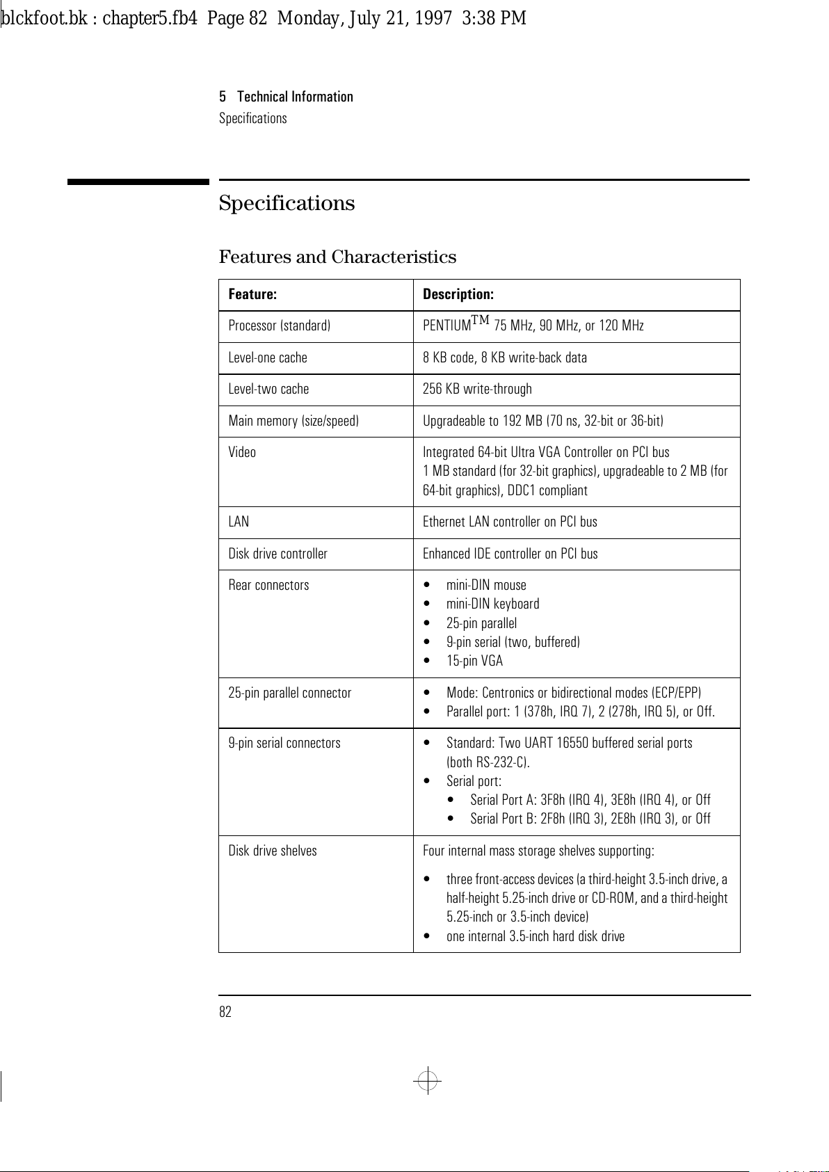
5 Technical Information
Specifications
82 English
Specifications
Features and Characteristics
Feature: Description:
Processor (standard) PENTIUM
TM
75 MHz, 90 MHz, or 120 MHz
Level-one cache 8 KB code, 8 KB write-back data
Level-two cache 256 KB write-through
Main memory (size/speed) Upgradeable to 192 MB (70 ns, 32-bit or 36-bit)
Video Integrated 64-bit Ultra VGA Controller on PCI bus
1 MB standard (for 32-bit graphics), upgradeable to 2 MB (for
64-bit graphics), DDC1 compliant
LAN Ethernet LAN controller on PCI bus
Disk drive controller Enhanced IDE controller on PCI bus
Rear connectors
•
mini-DIN mouse
•
mini-DIN keyboard
•
25-pin parallel
•
9-pin serial (two, buffered)
•
15-pin VGA
25-pin parallel connector
•
Mode: Centronics or bidirectional modes (ECP/EPP)
•
Parallel port: 1 (378h, IRQ 7), 2 (278h, IRQ 5), or Off.
9-pin serial connectors
•
Standard: Two UART 16550 buffered serial ports
(both RS-232-C).
•
Serial port:
•
Serial Port A: 3F8h (IRQ 4), 3E8h (IRQ 4), or Off
•
Serial Port B: 2F8h (IRQ 3), 2E8h (IRQ 3), or Off
Disk drive shelves Four internal mass storage shelves supporting:
•
three front-access devices (a third-height 3.5-inch drive, a
half-height 5.25-inch drive or CD-ROM, and a third-height
5.25-inch or 3.5-inch device)
•
one internal 3.5-inch hard disk drive
blckfoot.bk : chapter5.fb4 Page 82 Monday, July 21, 1997 3:38 PM
Page 95
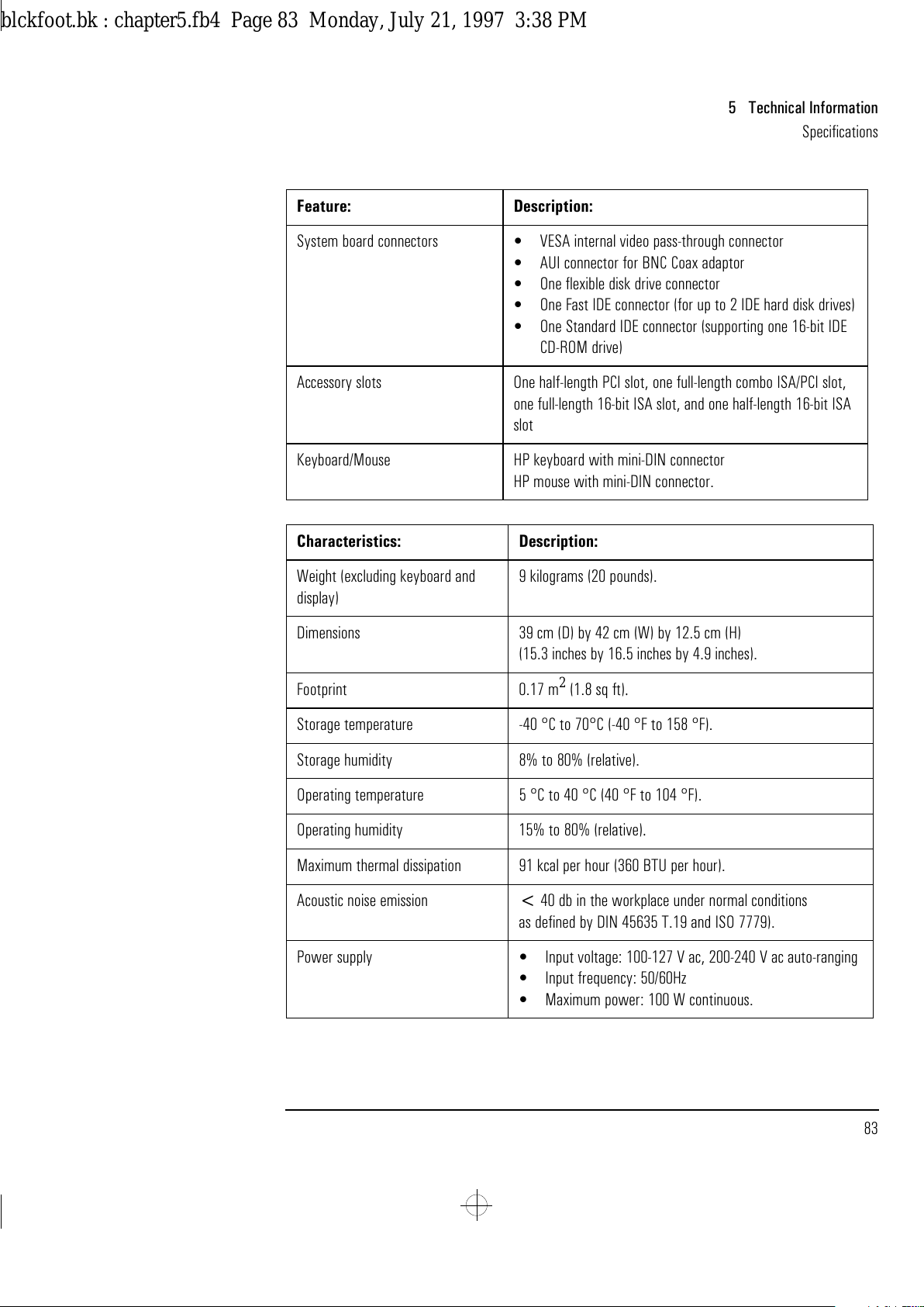
English 83
5 Technical Information
Specifications
System board connectors
•
VESA internal video pass-through connector
•
AUI connector for BNC Coax adaptor
•
One flexible disk drive connector
•
One Fast IDE connector (for up to 2 IDE hard disk drives)
•
One Standard IDE connector (supporting one 16-bit IDE
CD-ROM drive)
Accessory slots One half-length PCI slot, one full-length combo ISA/PCI slot,
one full-length 16-bit ISA slot, and one half-length 16-bit ISA
slot
Keyboard/Mouse HP keyboard with mini-DIN connector
HP mouse with mini-DIN connector.
Characteristics: Description:
Weight (excluding keyboard and
display)
9 kilograms (20 pounds).
Dimensions 39 cm (D) by 42 cm (W) by 12.5 cm (H)
(15.3 inches by 16.5 inches by 4.9 inches).
Footprint 0.17 m
2
(1.8 sq ft).
Storage temperature -40 °C to 70°C (-40 °F to 158 °F).
Storage humidity 8% to 80% (relative).
Operating temperature 5 °C to 40 °C (40 °F to 104 °F).
Operating humidity 15% to 80% (relative)
.
Maximum thermal dissipation 91 kcal per hour (360 BTU per hour).
Acoustic noise emission < 40 db in the workplace under normal conditions
as defined by DIN 45635 T.19 and ISO 7779).
Power supply
•
Input voltage: 100-127 V ac, 200-240 V ac auto-ranging
•
Input frequency: 50/60Hz
•
Maximum power: 100 W continuous.
Feature: Description:
blckfoot.bk : chapter5.fb4 Page 83 Monday, July 21, 1997 3:38 PM
Page 96
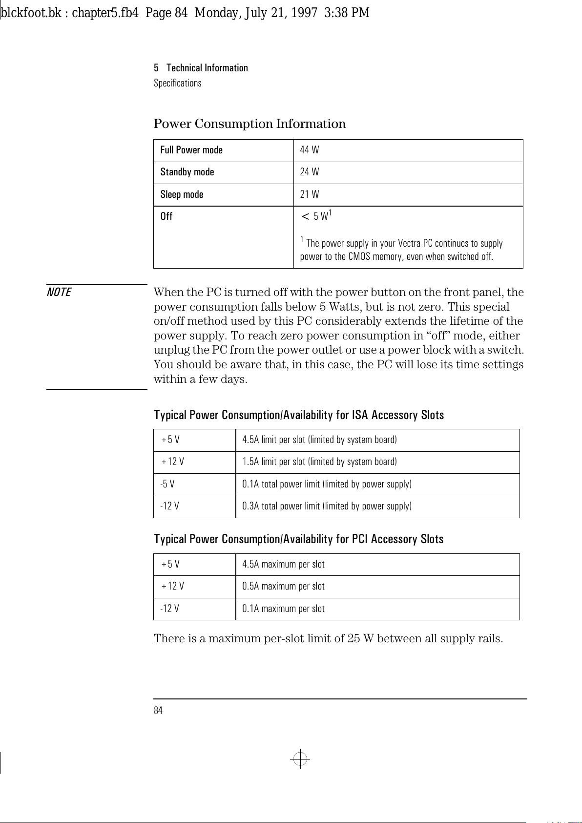
5 Technical Information
Specifications
84 English
Power Consumption Information
NOTE When the PC is turned off with the power button on the front panel, the
power consumption falls below 5 Watts, but is not zero. This special
on/off method used by this PC considerably extends the lifetime of the
power supply. To reach zero power consumption in “off” mode, either
unplug the PC from the power outlet or use a power block with a switch.
You should be aware that, in this case, the PC will lose its time settings
within a few days.
Typical Power Consumption/Availability for ISA Accessory Slots
Typical Power Consumption/Availability for PCI Accessory Slots
There is a maximum per-slot limit of 25 W between all supply rails.
Full Power mode 44 W
Standby mode 24 W
Sleep mode 21 W
Off < 5 W
1
1
The power supply in your Vectra PC continues to supply
power to the CMOS memory, even when switched off.
+5 V 4.5A limit per slot (limited by system board)
+12 V 1.5A limit per slot (limited by system board)
-5 V 0.1A total power limit (limited by power supply)
-12 V 0.3A total power limit (limited by power supply)
+5 V 4.5A maximum per slot
+12 V 0.5A maximum per slot
-12 V 0.1A maximum per slot
blckfoot.bk : chapter5.fb4 Page 84 Monday, July 21, 1997 3:38 PM
Page 97
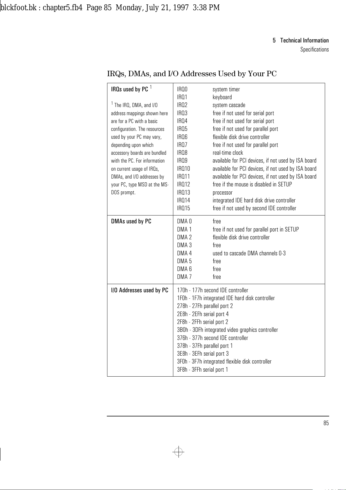
English 85
5 Technical Information
Specifications
IRQs, DMAs, and I/O Addresses Used by Your PC
IRQs used by PC
1
1
The IRQ, DMA, and I/O
address mappings shown here
are for a PC with a basic
configuration. The resources
used by your PC may vary,
depending upon which
accessory boards are bundled
with the PC. For information
on current usage of IRQs,
DMAs, and I/O addresses by
your PC, type MSD at the MS-
DOS prompt.
IRQ0 system timer
IRQ1 keyboard
IRQ2 system cascade
IRQ3 free if not used for serial port
IRQ4 free if not used for serial port
IRQ5 free if not used for parallel port
IRQ6 flexible disk drive controller
IRQ7 free if not used for parallel port
IRQ8 real-time clock
IRQ9 available for PCI devices, if not used by ISA board
IRQ10 available for PCI devices, if not used by ISA board
IRQ11 available for PCI devices, if not used by ISA board
IRQ12 free if the mouse is disabled in SETUP
IRQ13 processor
IRQ14 integrated IDE hard disk drive controller
IRQ15 free if not used by second IDE controller
DMAs used by PC DMA 0 free
DMA 1 free if not used for parallel port in SETUP
DMA 2 flexible disk drive controller
DMA 3 free
DMA 4 used to cascade DMA channels 0-3
DMA 5 free
DMA 6 free
DMA 7 free
I/O Addresses used by PC 170h - 177h second IDE controller
1F0h - 1F7h integrated IDE hard disk controller
278h - 27Fh parallel port 2
2E8h - 2EFh serial port 4
2F8h - 2FFh serial port 2
3B0h - 3DFh integrated video graphics controller
376h - 377h second IDE controller
378h - 37Fh parallel port 1
3E8h - 3EFh serial port 3
3F0h - 3F7h integrated flexible disk controller
3F8h - 3FFh serial port 1
blckfoot.bk : chapter5.fb4 Page 85 Monday, July 21, 1997 3:38 PM
Page 98
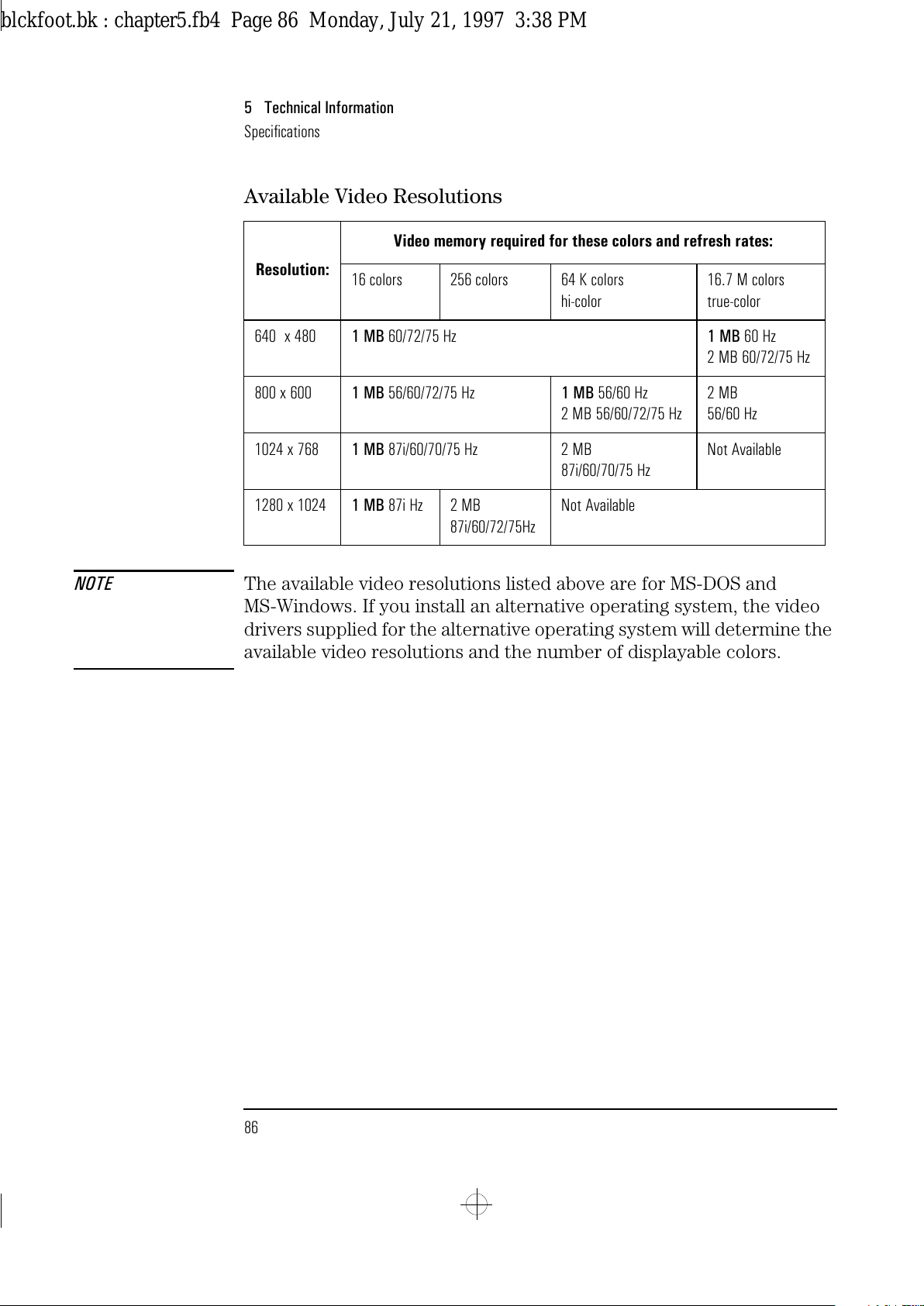
5 Technical Information
Specifications
86 English
Available Video Resolutions
NOTE The available video resolutions listed above are for MS-DOS and
MS-Windows. If you install an alternative operating system, the video
drivers supplied for the alternative operating system will determine the
available video resolutions and the number of displayable colors.
Resolution:
Video memory required for these colors and refresh rates:
16 colors 256 colors 64 K colors
hi-color
16.7 M colors
true-color
640 x 480 1 MB 60/72/75 Hz 1 MB 60 Hz
2 MB 60/72/75 Hz
800 x 600 1 MB 56/60/72/75 Hz 1 MB 56/60 Hz
2 MB 56/60/72/75 Hz
2 MB
56/60 Hz
1024 x 768 1 MB 87i/60/70/75 Hz 2 MB
87i/60/70/75 Hz
Not Available
1280 x 1024 1 MB 87i Hz 2 MB
87i/60/72/75Hz
Not Available
blckfoot.bk : chapter5.fb4 Page 86 Monday, July 21, 1997 3:38 PM
Page 99
English 87
5 Technical Information
Recycling Your PC
Recycling Your PC
HP has a strong commitment toward the environment. Your HP
Personal Computer has been designed to respect the environment as
much as possible.
HP can also take your old PC back for recycling when it reaches the
end of its useful life.
In fact, HP has a product take back program in several countries. The
collected equipment is sent to one of HP’s recycling facilities in Europe
or the USA. As many parts as possible are reused. The remainder is
recycled. Special care is taken for batteries and other potentially toxic
substances, which are reduced into non-harmful components through a
special chemical process.
If you require more details about HP’s product take back program,
contact your dealer or your nearest HP Sales Office.
blckfoot.bk : chapter5.fb4 Page 87 Monday, July 21, 1997 3:38 PM
Page 100
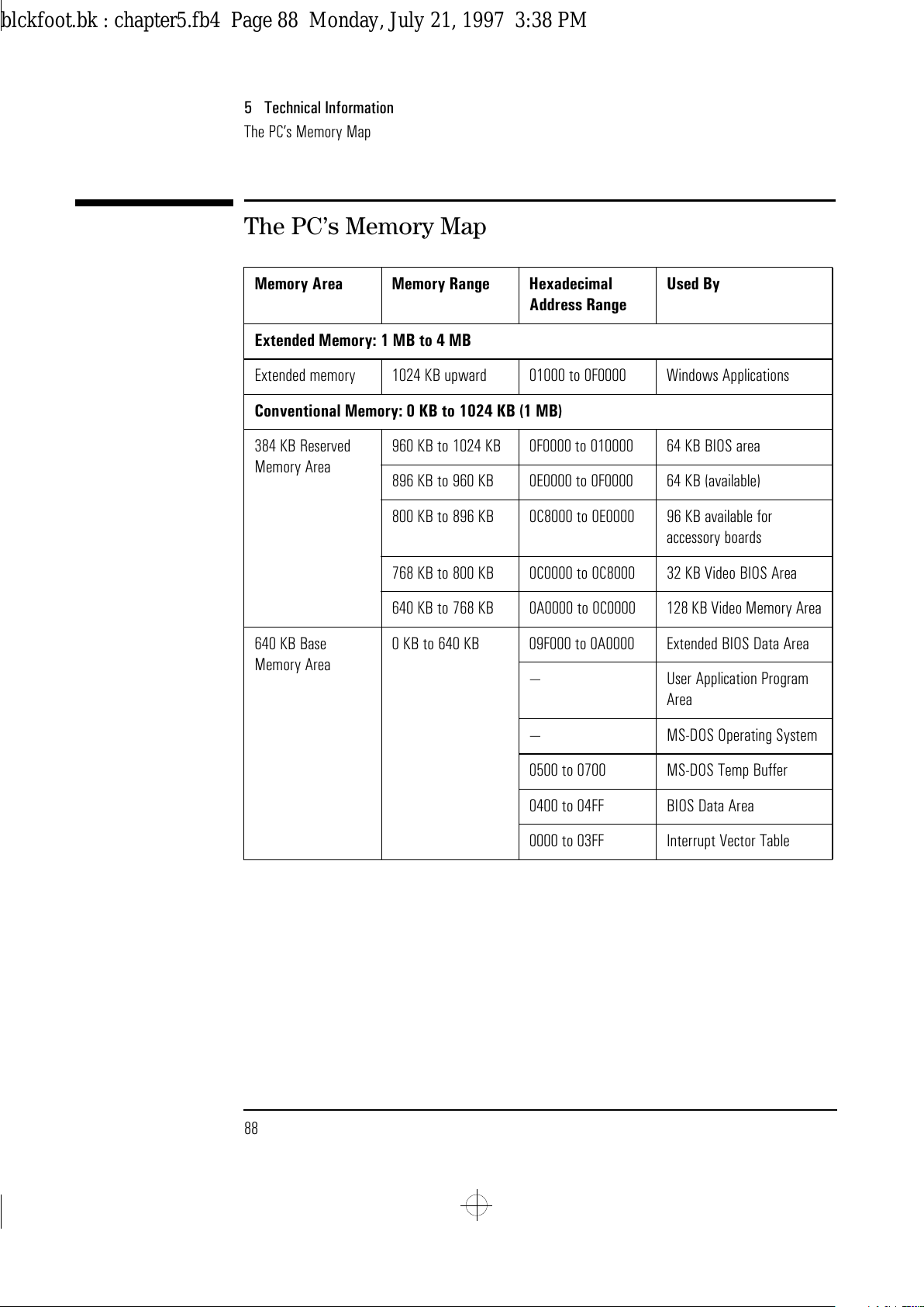
5 Technical Information
The PC’s Memory Map
88 English
The PC’s Memory Map
Memory Area Memory Range Hexadecimal
Address Range
Used By
Extended Memory: 1 MB to 4 MB
Extended memory 1024 KB upward 01000 to 0F0000 Windows Applications
Conventional Memory: 0 KB to 1024 KB (1 MB)
384 KB Reserved
Memory Area
960 KB to 1024 KB 0F0000 to 010000 64 KB BIOS area
896 KB to 960 KB 0E0000 to 0F0000 64 KB (available)
800 KB to 896 KB 0C8000 to 0E0000 96 KB available for
accessory boards
768 KB to 800 KB 0C0000 to 0C8000 32 KB Video BIOS Area
640 KB to 768 KB 0A0000 to 0C0000 128 KB Video Memory Area
640 KB Base
Memory Area
0 KB to 640 KB 09F000 to 0A0000 Extended BIOS Data Area
— User Application Program
Area
— MS-DOS Operating System
0500 to 0700 MS-DOS Temp Buffer
0400 to 04FF BIOS Data Area
0000 to 03FF Interrupt Vector Table
blckfoot.bk : chapter5.fb4 Page 88 Monday, July 21, 1997 3:38 PM
 Loading...