

Page 1

HP V241a/V241 LED Backlit Monitor
User Guide
Page 2

1
© 2013 Hewlett-Pac kard Development Company, L. P.
Microsoft, Windows, and Windows Vista are either trademarks or registered t r ademarks of Microsoft
Corporation in the United St at es and/or other countries.
The only warranties for HP products and services are set fort h in the express warranty statements
accompanying such products and services. Nothing herein should be construe d as constituting an
additional warranty . HP sh all n ot be liable for technical or editorial errors or omissions contained herein.
This document contains p r opr iet ar y information that is protect ed by copyright. No part of this document
may be photocopied, reproduced, or translated to a not her language without the prior writ t en consent of
Hewlett-Packard Company.
First Edition (June 2013)
Document Part Number: 741027-001
Page 3

2
Chapter I. Introduction
1.1 Features
Multilingual OSD adjustment
Compatible with IBM VGA, extended VGA, VESA VGA, SVGA, XG A, and SXGA modes
Wide range of applicable voltages (AC 100-240V 50/60Hz ) enables direct use without any
setting.
Plug-and-play VESA DDC1/ 2B Standard. Comp at i ble with Windows 9x / 2000 / XP / 7 / 8/Vista
operation systems
1.2 Check list
Please make sure the follow ing it ems are included with your LCD m onitor;
The monitor (and the pedestal)
Stand
Power cord
VGA cable
DVI cable (Optional)
Audio cable (only for V241a)
Documentation and s oftware Disc
Setup poster
Warranty certificate (Optional)
If any of these items are missing, please contact your dealer for technical support and custom
service.
Note: Be sure to save original box and all packing mater ials for future transport.
Page 4
3
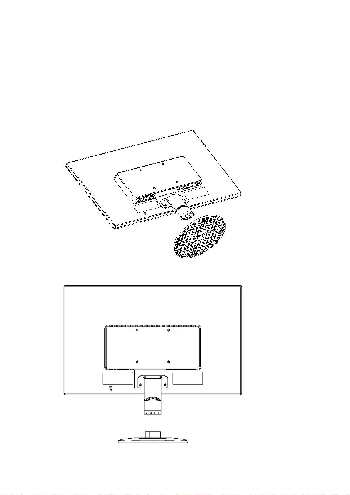
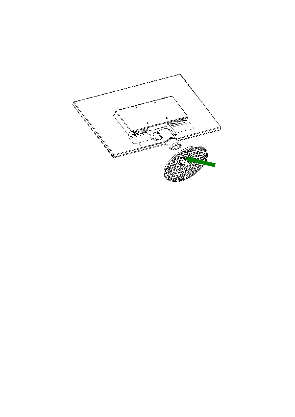
Chapter II. Installation
2.1 Install the pedestal
Please follow the steps illust r at ed below to install the pedestal.
Page 5

4
2.2 Connect your monitor to your computer
1. Power off and unplug your computer.
2. Connect the 15-Pin ends of the signal c able to the VGA port of your m onitor and the VGA OUT jack
on the back of your computer. Secur e t he screws on both ends of the signal cable.
3. Connect one end of power cord to the monitor, t hen connect the other end of the power cords to the
nearest electrical outlet.
4. Power on your computer and monitor. I f y our mo nitor displays an image, the inst al lat i on has been
successfully done. If the mo nit or does not display any image, check all the connections.
Cautions: 1. For installation, please complete signal cord connec tion before plugging the power cor d
into the electrical outlet to avoid damaging the monitor.
2. During installation, please support the front fr ame w ith your han d at its cent er of gravity to
avoid dropping and damaging the monitor.
Overview of the ports on the monitor:
1. AC power supply input
2. AUDIO signal input (V241a only)
3. DVI signal input
4. VGA signal input
Page 6
5
2.3 Disconnect the pedestal for shipping
Press the clip button on the pedesta l and remove the pedestal from the stand.
Page 7

6
Chapter III. Monitor overview
Overview of front panel controls
Page 8

7
Chapter IV. Operational Instruction
4.1 Power ON/OFF Switch
Press this button to power on/ of f your monitor. Note: The ON/OF F switch does not disconne ct your
monitor from the main voltage. To completely disconnect t he m ai n voltage, please remove the
power plug from the socket.
4.2 Power indicator
The power LED is blue when the monitor operates nor m al ly. If the monitor runs in power-saving
mode, this indicator chan ges to amber. When the monit or i s turned off, this indicator is unlit.
4.3 Menu features
All the following features of your monitor can be accesse d and adjusted by using the on screen
display (menu) system.
1. If your monitor is not powered on, press the "Power” button to turn it on.
2. Press the "Menu” button to activate the OSD menu. The OS D main menu will be displayed.
3. To view the main menu or submenu, pr ess t he “+” on the front panel o f your monitor to scroll up
or the “-” to scroll down. Then press the "OK” button to select a high li ght ed function.
When the highlight scrolls down to the bottom of the menu, it r et ur ns t o top of the menu. When the
highlight scrolls up to the top of the menu, it ret ur ns to bottom of the menu."
4. To adjust the selected option, press the “+” or “-” button.
5. Select “Save” and return. If you do not want to save the sett ing, select “Cancel” fro m the
submenu or “Exit” from the main menu.
6. Press the “Menu” button to exit from the OSD menu.
Page 9

8
4.4 OSD operational i ns tr uc t ions
option
white.
Icon
Main menu
Submenu option Note
To adjust the brightness level of the
Brightness
screen. The factory default range is
90.
To adjust the contrast level of the
Contrast
screen.The factory default range is
80.
Color
Selects the screen color.The
factory is 6500K or Custom
color,depending on the mode.
Warm- 5000K
Changes color to slightly reddish
Standard- 6500K Uses standard colors (default).
Cool- 9300K
Change color to slightly blueish
white.
Selects and adjusts your own color
scales:
Red Color – sets y our ow n red col or
levels.
Custom (RGB)
Green Color – sets your own green
color levels.
Blue Color – sets your own blue
color levels.
To adjust the image on the screen.
Image control
The ambient brightness sensor can
also be enabled or disabled (only
applicable to some models)
To automatically adjust the image
Auto-adjustment
on the screen (only applicable to
VGA input).
To adjust the clock phase of the
screen.
Clock and Phase
This adjustment elimin ates al l
horizontal noises to enable clearer
and more lifelike images and
Page 10

9
characters (only applicable to VGA
input).
proportional image.
monitor.
seconds) after the last pressing the
input)
To adjust the horizontal position of
Horizontal position
an image (only applicable to VGA
To adjust the vertical position of an
Vertical position
image (only applicable to VGA
input).
Selects the method on how
displayed information on the
monitor will be formatted.Select
Fill to Screen – image fills the entir e
screen and may look distort ed or
Custom Scaling
elongated because of
non-proportional scaling of height
and width.
Fill to Aspect Ration – image is
sized to fit the screen and maintai ns
OSD Control
Sharppness
Dynamic Contrast
OSD position
Adjusts the screen imageto look
sharper or soft. (range:1~6)
Turns Dynamic Contrast Ratio On
or Off.The factory default is Off.
Provides a menu for adjusting the
on-screen display(OSD)control.
To adjust OSD positio n for your
To adjust the visual position of the
Horizontal OSD
Position
OSD menu to the right or left of the
screen. The factory defaul t
horizontal position value is 97.
To adjust the visual position of the
Vertical OSD
Position
OSD menu up or down the screen.
The factory default vertical position
value is 13.
To adjust the transparency to
OSD Transparency
enable transparent bac kground
information under the OSD .
(range:0~7)
OSD Timeout
To set the OSD display time (in
Page 11

10
Management
management for your monit or .
The factory default setting is On.
on-off setting.
Auto-Sleep Mode
Power Saver Mode
button. The factor y default setting is
“30 seconds”.
To select the function o f pow er
To enable the energy-saving
function, Select
On
off
The factory default setting is On.
The “Power Saver Mode”control
allow quick user selection of
reduced power modes while the
monitor is still in use.Select:
Off
10% Savings
20% Savings
30% Savings
40% Savings
50%Savings
Restores power to the monitor
following an unexpected removal of
power. Select:
Power-On Recall
On
Off
The factory default is On.
The resolution, refresh rate and
frequency information will be
Mode Display
displayed when the OSD main
menu is accessed. Please select
“On” or “Off” as the factory default
The operational status of your
monitor will be displayed when you
power on your monitor. To select
the positions where the status
Monitor Status
information is display e d:
Top
Middle
Bottom
Off
The factory default setting is “Top”
DDC/CI support
Controlling some OSD menu
functions, such as brightness,
Page 12

11
set as “Off”, it will be off all the time.
internal audio test.
awakened from the sleeping mode.
default is English.
information about your moni t or .
Bezel Power LED
Audio(For V241a
only)
Sleep timer
contrast and color temperature, on
your computer is allowed.
This feature can be set as “On” or
“Off”. The factory defaul t setting is
On.
Power on/off the indicator (LED) on
the power button. If the indicator is
1. To adjust the volume level of the
speaker. The factory default
range is 90.
2. Speaker Self-Test : There shall
also be a provision made for an
The following timer adjustment
menu options are available:
Set current time – to set the current
time in hours and minutes.
Set sleep time – to set the desired
time when your monitor works
under the sleeping mode.
Set On time – to set the desired
time when your monitor is
Language
Information
Factory Reset
Input Control
Timer - Set “On’ or “Off” status for
the Sleep Timer. The default setting
is “Off”.
Sleep Now – to activate the sleep
mode for your monitor
Selects the language in which the
OSD menu is displayed.The factory
To select and display important
The factory default settings will be
reset
When the monitor is connected to
two active and valid video sources,
switching between the video input
source is available. Switching the
Page 13

12
video input signal so urces may take
you several seconds.
EXIT Exits the OSD menu screen.
Page 14

13
Chapter V. Technical Information
5.1 Factory preset displa y mode
Criteria Resolution Horizontal frequency Vertical frequency
1 640X480 @60 Hz 31.469 59.94
2 720X400 @70 Hz 31.469 70.087
3 800X600 @60 Hz 37.879 60.317
4 1024X768 @60 Hz 48.363 60.004
5 1280X720 @60 Hz 45.00 60.00
6 1280X1024 @ 60 Hz 63.981 60.02
7 1440X900 @60 Hz 55.935 59.887
8 1600X900 @60 Hz 60.00 60.00
9 1680X1050@60 Hz 65.29 60.00
10 1920X1080@ 60Hz 67.50 60.00
Note: The factory preset disp lay mode is subject to change w it hout notice.
Page 15

14
5.2 Product specifications
2
Size 23.6" wide screen
Max. resolution 1920 x 1080 @ 60 Hz
Recommended resoluti on 1920 x 1080 @ 60 Hz
Horizontal frequency 24-94 kHz
Vertical frequency 50-75 Hz
Viewable size 521.28x 293.22 mm
Viewable angle 170 (H) 160 (V)
Pitching angle -5º to 20º
Pixel frequency 170 MHz
OSD functions Brightness, Contrast, I ma ge Control, OSD control, Languages,
Color, Management, I nformation, Factory Reset, Input Control,
Exit,
Size (Packing) 634 ( L) x 125(W) x 475 (H) mm
Net weight/ Gross weight 4.0 KG / 5.8 KG
Power supply 100-240VAC,50/60Hz
Altitude (under operatio nal condition)
Altitude (under storing co ndition)
Input signal VGA, DVI and Audio(Only for V241a )
Contrast 1000: 1
Brightness 250 cd/m
Response time 5 ms
Color displayed 16.7 M
Power (max) V241a:30 W , V241:26W
Operational environment
Storing environment
0 ~ 5000 m (0 ~16400 feet)
0 ~ 12192 m (0 ~ 40,000 feet)
Temperature: 5-35℃; humidity: 20% ~ 80%
Temperature: -20-60℃; humidity: 5% ~ 95%
Page 16

15
5.3 Signal cable connector
PIN Signal
1 Red Signal
2 Green Signal
3 Blue Signal
4 Ground
5 Cable testing
6 Red Signal Ground
7 Green Signal Ground
8 Blue Signal Ground
9 5 VDC
10 Null
11 Ground
12 SDA (for DDC)
13 Horizontal synchronizat ion
14 Vertical synchronizati on
15 SCL (for DDC)
VGA Interface
Page 17

16
PIN SIGNAL
10 TMDS Data 1 +
11 TMDS Data 1 / 3 Shield
12 TMDS Data 3 13 TMDS Data 3 +
14 +3.3/+5V Power ( from PC)
15 Ground (Retur n f or + 5 V)
16 Hot Plug Detect
17 TMDS Data 0 18 TMDS Data 0 +
19 TMDS Data 0 / 5 Shield
20 TMDS Data 5 21 TMDS Data 5 +
22 TMDS Clock Shield
23 TMDS Clock +
24 TMDS Clock -
DVI Interface
1 TMDS Data 2 2 TMDS Data 2 +
3 TMDS Data 2 / 4 Shield
4 TMDS Data 4 5 TMDS Data 4 +
6 DDC Clock
7 DDC Data
8 No Connect
9 TMDS Data 1 -
Page 18

17
PIN SIGNAL
1 GND
2 LEFT AUDIO CHANAL
3 RIGHT AUDIO CHANAL
4 GND
5 GND
Audio interface(Only for V241a)
5.4 Panel testing
The ratio of valid pixels on each L CD screen r eache s 99.99% or h igher. Howe ver, less than 0.01% of t he
pixels may cause dark dots displayed on the screen.
Page 19

18
A Safety and Maintenance Guidelines
Important Safety Information
A power cord is included with t he m onitor . If another cord is used, use only a power source and
connection appropriate for t his monitor. For inf or mation on t he correct power cor d set to use with
the monitor, refer to the “P ower Cord Set Requirements” section in Agency Regulatory Notices.
Warning! To reduce the risk of electric shoc k or dam age t o the equipment:
• Do not disable the power cord gr ounding feature. The groundi ng plug is an important safety
feature.
• Plug the power cord into an easily accessible grounded o ut let .
• Disconnect the power fro m the equipment by unplugging t he pow er cord from the electrical
outlet.
For your safety, do not place any t hing on power cords or cables. Arrange them so that no one may
accidentally step on or t r ip over them. Do not pull on a cord or cable. When unplugging from the
electrical outlet, grasp the cord by the plug.
To reduce the risk of serious in jury, read the Safety and Comfort Guide. It describes proper
workstation, setup, posture, and health and work ha bits f or computer users, and provides important
electrical and mechanical safety information. This g uid e is l ocated on the Web at
http://www.hp.com/ergo and/or on the document at ion CD, if one is included with the mo nit or .
CAUTION: For the protection of the mon itor , as w ell as the computer, connect all power cords for
the computer and its peripher al devices (such as a monitor, printer and scanner) to some for m o f
surge protection device s uch as a power strip or Uninter r upt ible Power Supply (UPS). Not all power
strips provide surge protection; the power strips mu st be specifically labeled as having this ability.
Use a power strip whose manufacturer offers a Damage Replacement Policy so you can rep lace the
equipment, if surge protection fails.
Use the appropriate and c orrect ly siz ed fur niture d esign ed to pr oper ly supp ort y our HP LC D mon itor.
WARNING! LCD monitors that are inappropr iately situated on dressers, bookc ases, shelves,
desks, speakers, chests, or carts may fall over and cause personal injury.
Care should be taken to route all cor ds and cables connected to t he LCD monitor so that they can
not be pulled, grabbed, or t r ipped over.
Page 20

19
Safety Precautions
Use only a power source and connection compatible w ith this monitor, as indicate d on the label/
back plate of the monitor.
Be sure the total ampere rat ing of the products connected t o t he out let does not exceed the
current rating of the electri ca l outlet, and the total ampere ratin g of the products connected to the
power cord does not exceed the rating of the power cord. Look on the power label to deter min e t he
ampere rating (Amps or A ) for each device.
Install your monitor near a power outlet that you can eas ily r each. Disconnect the monitor by
grasping the plug firmly and pulling it from the outlet. Nev er disconnect the monitor by pulling t he
cord.
Do not allow anything to r est on the power cord. Do not walk on the cord.
Page 21

20
Maintenance Guidelines
To enhance the performance and extend the life of your monitor:
● Do not open your monitor cabinet or attempt to service this product yourself. Adj ust only
those controls that are cov er ed in t he operating instructions. I f your monitor is not
operating properly or has been dropped or damaged, cont act your HP authorized dealer,
reseller, or service provider.
● Use only a power source and connection appropriate for this monitor, as indicated on the
label/ back plate of the monitor.
● Be sure the total ampere rating of the products connected to the outlet does not exceed the
current rating of the electr i ca l o utlet, and the total ampere rat ing of the products connected
to the cord does not exceed the rat ing of the cord. Check the power label to determine the
ampere rating (AMPS or A) for each device.
● Install your monitor near an outlet that you can easily reach. Discon nect the monitor by
grasping the plug firmly and pulling it from the outlet. Never disconnect the monitor by
pulling the cord.
● Turn your monitor off when not in use. You can substantially increase the life expectancy of
your monitor by using a scr een sa ver program and turnin g off the monitor when not in us e.
Note: The HP Warranty does not cover monitors with a burned-in image.
● Slots and openings in the cabinet are provided for ventilation. These openings must not be
blocked or covered. Never push objects of any kind i nt o cabinet slots or other openings.
● Do not drop your monitor or place it on an unstable surface.
● Do not allow anything to rest on the power cord. Do not walk on the cord.
● Keep your monitor in a well-ventilated area, away from excessive light, heat or moisture.
● When removing the monitor base, you must lay the monitor face down on a soft area to
prevent it from being scratched, defaced, or broken.
Cleaning your monitor
1. Turn off the monitor and the co mputer .
2. Unplug the monitor from the wall outlet.
3. Clean the monitor plastics w ith a clean cloth dampened with wat er .
4. Clean the monitor screen with an antistatic screen cleaner.
CAUTION: Do not use benzene, t hinner, ammonia, or any ot her volatil e substances to clean
the monitor or the screen. These chemicals may damage the ca binet finish as well as the
screen.
Shipping the monitor
Keep the original packing box in a storage area. You may need it lat er i f you move or ship your
monitor. To prepare the monit or f or sh i pping, refer to Chapter 2, “Disconnect the Pedestal for
Shipping.”
Page 22

21
B Agency Regulatory Notices
Federal Communications Commission Notice
This equipment has been tested and found to comply with the limits for a Class B digital device, pursuant to
Part 15 of the FCC Rules. These limits are designed to provide reasonable protection against harmful
interference in a residential installation. This equipment generates, uses, and can radiate radio frequency
energy and, if not installed and used in accordanc e with the instructions, may cause harmful interference to
radio communications. However, there is no guarantee that interference will not occur in a particular
installation.
If this equipment does cause harmful interference to radio or television reception, which can be determined by
turning the equipment off and on, the user is encouraged to try to correct the interference by one or more of
the following measures:
● Reorient or relocate the receiving antenna.
● Increase the separation between the equipment and receiver.
● Connect the equipment to an outlet on a circuit different from that to which the receiver is connected.
● Consult the dealer or an experienced radio or television technician for help.
Modifications
The FCC requires the user to be notified that any changes or modifications made to this device that are not
expressly approved by HP may void the user's authority to operate the equipment.
Cables
To maintain compliance with FCC Rules and Regulations, connections to this device must be made with
shielded cables having metallic RFI/EMI connector hoods.
Declaration of Conformity for products marked with the FCC logo
(United States only)
This device complies with Part 15 of the FCC Rules. Operation is subject to the following 2 conditions:
1. This device may not cause harmful interference.
2. This device must accept any interference received, including interference that may cause undesired
operation.
If you have questions about the product that are not related to this declaration, write to
Hewlett-Packard Company
P. O. Box 692000, Mail Stop 530113
Houston, TX 77269-2000
For questions regarding this FCC declaration, write to
Hewlett-Packard Company
P. O. Box 692000, Mail Sto p 51010 1
Houston, TX 77269-2000
or call HP at 281-514-3333
To identify your product, refer to the part, series, or model number located on the product.
Page 23

22
Canadian Notice
This Class B digital apparatus meets all requirements of the Canadian Interference-Causing Equipment
Regulations. CAN ICES-3(B)/NMB-3(B)
Avis Canadien
Cet appareil numérique de la classe B respecte toutes les exigences du Règlement sur le matériel
brouilleur du Canada.
European Union Regulatory Notice
Products bearing the CE marking comply with one or more of the following EU Directives as may
be applicable:
Low Voltage Directive 2006/95/EC; EMC Directive 2004/108/EC; Ecodesign Directive
2009/125/EC; R&TTE Directive 1999/5/EC; RoHS Directive 2011/65/EU
Compliance with these directives is assessed using applicable European Harmonised Standards.
The full Declaration of Conformity can be found at the following web site:
http://www.hp.eu/certificates
(Search with the product model name or its Regulatory Model Number (RMN), which may be
found on the regulatory label.)
The point of contact for regulatory matters is Hewlett-Packard GmbH, Dept./MS:HQ-TRE,
Herrenberger Strasse 140, 71034 Boeblingen, GERMANY.
German Ergonomics Notice
HP products which bear the “GS” approval mark, when forming part of a system comprising HP brand
computers, keyboards and monitors that bear the “GS” approval mark, meet the applicable ergonomic
requirements. The installation guides included with the products provide configuration information.
Power Cord Set Requirements
The monitor power supp ly is provid ed wit h Aut om atic Lin e Sw itchi ng ( ALS). T his featur e al lows th e
monitor to operate on input voltages between 100–120V or 200–240V.
The power cord set (flexible cord or wall plug) received with the monitor meets the requirements
for use in the country wher e you purchased the equipment.
If you need to obtain a po wer cord for a di ffere nt co unt ry , y ou should purc hase a p ow er cord that is
approved for use in that count r y.
The power cord must be rated for t he product and for the voltage and current marked on the
product's electrical ratings label. The voltage and current rating of the cord shoul d be gr eat er t han
the voltage and current rat ing marked on the product. In additio n, the cross-sectional area o f t he
wire must be a minimum of 0.75 mm² or 18 AWG, and the length of the cord must be between 6
feet (1.8 m) and 12 feet (3.6 m).I f y ou have questions about the type of pow er cord to use, contact
Page 24

23
an authorized HP service pr ovider.
A power cord should be ro ut ed so t hat it is not likely to be walked on or pinched by items placed
upon it or against it. Particular attention should be paid to the plug, electrical outlet, and the point
where the cord exits from t he pr oduct.
Product Environmental Notices
ENERGY STAR○
HP Displays marked with the ENERGY STAR
U.S. Environmental Protect ion A gency (EPA) ENERGY ST AR
STAR
Partner, Hewlett Packard Company has determined that this product meets the EN ERGY STAR
program requirements for display energy efficiency.
The following ENERGY STAR
displays:
The ENERGY STAR○R program specifications for displays and computers were created by
the EPA to promote energy efficiency and reduce air pollut io n through more energy-efficient
equipment in homes, offices, and factories. One wa y products achieve this goal is by using the
Microsoft Windows power management feature to reduce power consumption when the product is
not in use. The power management feature enables the computer to initiat e a low -power or
“sleep” mode after a perio d of us er inactivity. When used with an external ENERGY STAR
qualified display, this feat ur e also supports similar pow er ma nagement features for the di splay. To
take advantage of these potential energy savings, u ser s should use the default power
management settings that are provided with ENERGY STAR qualified computers and displays.
The default power management settings on ENERGY STAR
behave in the following ways when the system is operating on A C p ower:
ENERGY STAR
qualified displays resu me operation when the user resumes use of the computer . Examples
include the user pressing the power/sleep button, receiving an input signal from an input device,
receiving an input sig na l from a net wor k conne ct ion with t he Wake On L AN (WOL) feature enable d,
etc.
Additional information on the ENERGY STAR○R program, its environme ntal benefits and the
potential energy and financial savings of the p ow er management feature can be found on the EPA
ENERGY STAR
at
R
○
• Turn off an external display after 15 m inut es of user inactivity
• Initiate a low power sleep mode for t he computer after 30 minutes of user inactivity
http://www.energystar.gov/powermanagement,
R
Qualification
R
○
certification mark meet t he r equirements of the
R
○
program. The EPA ENERGY
certification mark does not imply endorsement by the EPA. As an ENERGY STAR○
R
○
certification mark ap pear s on all ENERGY STAR
R
○
qualified computers ar e pr ese t t o
R
○
qualified
R
○
qualified computers exit the l ow power sleep mode and EN ERGY STAR
R
○
Power Management Web site
○
R
○
R
R
○
R
 Loading...