

HP TouchSmart Elite 7320 Maintenance & Service Manual

Maintenance & Service Guide
HP TouchSmart Elite 7320 All-in-One Business
PC

© Copyright 2011, 2012 Hewlett-Packard
Development Company, L.P. The
information contained herein is subject to
change without notice.
Microsoft and Windows are trademarks of
Microsoft Corporation in the U.S. and other
countries.
The only warranties for HP products and
services are set forth in the express
warranty statements accompanying such
products and services. Nothing herein
should be construed as constituting an
additional warranty. HP shall not be liable
for technical or editorial errors or omissions
contained herein.
This document contains proprietary
information that is protected by copyright.
No part of this document may be
photocopied, reproduced, or translated to
another language without the prior written
consent of Hewlett-Packard Company.
Maintenance & Service Guide
HP TouchSmart Elite 7320 All-in-One
Business PC
Third Edition (May 2012)
First Edition (September 2011)
Document Part Number: 670575-003

About This Book
WARNING! Text set off in this manner indicates that failure to follow directions could result in bodily
harm or loss of life.
CAUTION: Text set off in this manner indicates that failure to follow directions could result in
damage to equipment or loss of information.
NOTE: Text set off in this manner provides important supplemental information.
iii

iv About This Book

Table of contents
1 Product Features ............................................................................................................................................ 1
Overview .............................................................................................................................................. 1
Front Components ................................................................................................................................ 3
Side Components ................................................................................................................................. 4
Rear Components ................................................................................................................................ 5
2 Installing and Customizing the Software ...................................................................................................... 6
Installing the Operating System ........................................................................................................... 6
Downloading Microsoft Windows Updates ........................................................................................... 6
Installing or Upgrading Device Drivers (Windows systems) ................................................................. 7
Accessing Disk Image (ISO) Files ........................................................................................................ 7
Protecting the Software ........................................................................................................................ 7
3 Computer Setup (F10) Utility ......................................................................................................................... 8
Computer Setup (F10) Utilities ............................................................................................................. 8
Using Computer Setup (F10) Utilities .................................................................................. 9
Computer Setup—File ....................................................................................................... 10
Computer Setup—Storage ................................................................................................ 11
Computer Setup—Security ................................................................................................ 13
Computer Setup—Power ................................................................................................... 16
Computer Setup—Advanced ............................................................................................. 17
4 Serial ATA (SATA) Drive Guidelines and Features .................................................................................... 18
SATA Hard Drives .............................................................................................................................. 18
SATA Hard Drive Cables .................................................................................................................... 18
SATA Data Cable .............................................................................................................. 18
SMART ATA Drives ............................................................................................................................ 19
Hard Drive Capacities ........................................................................................................................ 19
5 Routine Care and Disassembly Preparation .............................................................................................. 20
Electrostatic Discharge Information .................................................................................................... 20
v

Generating Static ............................................................................................................... 20
Preventing Electrostatic Damage to Equipment ................................................................ 21
Personal Grounding Methods and Equipment ................................................................... 21
Grounding the Work Area .................................................................................................. 22
Recommended Materials and Equipment .......................................................................... 22
Operating Guidelines .......................................................................................................................... 23
Routine Care ...................................................................................................................................... 23
General Cleaning Safety Precautions ................................................................................ 23
Cleaning the Computer Case ............................................................................................ 23
Cleaning the Keyboard ...................................................................................................... 24
Cleaning the Monitor .......................................................................................................... 24
Cleaning the Mouse ........................................................................................................... 25
Service Considerations ...................................................................................................................... 25
Tools and Software Requirements .................................................................................... 25
Screws ............................................................................................................................... 25
Cables and Connectors ..................................................................................................... 25
Hard Drives ........................................................................................................................ 26
Lithium Coin Cell Battery ................................................................................................... 26
6 Illustrated parts catalog ............................................................................................................................... 27
Computer major components ............................................................................................................. 27
Boards, memory, processors ............................................................................................................. 28
Mass storage devices ......................................................................................................................... 29
Cables ................................................................................................................................................ 30
Misc parts ........................................................................................................................................... 31
Keyboards (not illustrated) ................................................................................................................. 32
Sequential part number listing ............................................................................................................ 33
7 Removal and Replacement Procedures All-in One (AIO) Chassis ........................................................... 40
Preparing to Disassemble the Computer ........................................................................................... 40
Rear Cover ......................................................................................................................................... 41
Stand .................................................................................................................................................. 42
Memory Cover .................................................................................................................................... 43
Memory .............................................................................................................................................. 45
Optical Drive ....................................................................................................................................... 47
Hard Drive .......................................................................................................................................... 49
Converter Board ................................................................................................................................. 52
Touch Controller Board ...................................................................................................................... 54
Webcam Module ................................................................................................................................ 56
Speakers ............................................................................................................................................ 58
System Board Cover .......................................................................................................................... 60
vi

WLAN Module .................................................................................................................................... 62
TV Tuner Module ................................................................................................................................ 64
Heat sinks (Thermal Modules) ........................................................................................................... 66
Processor ........................................................................................................................................... 68
Graphics Card .................................................................................................................................... 70
Fan ..................................................................................................................................................... 72
VESA Cover with Kensington Lock Bracket ....................................................................................... 74
Optical and Hard Drive Cables and Connector .................................................................................. 76
Coaxal Cable Connector .................................................................................................................... 78
System Board ..................................................................................................................................... 80
Display Cable ..................................................................................................................................... 83
Front Bezel and Display Panel ........................................................................................................... 85
Cable Routing ..................................................................................................................................... 91
Appendix A Troubleshooting Without Diagnostics ...................................................................................... 92
Safety and Comfort ............................................................................................................................ 92
Before You Call for Technical Support ............................................................................................... 92
Helpful Hints ....................................................................................................................................... 93
Solving General Problems .................................................................................................................. 95
Solving Power Problems .................................................................................................................... 98
Solving Diskette Problems ................................................................................................................. 99
Solving Hard Drive Problems ........................................................................................................... 102
Solving Media Card Reader Problems ............................................................................................. 105
Solving Display Problems ................................................................................................................. 107
Solving Audio Problems ................................................................................................................... 111
Solving Printer Problems .................................................................................................................. 113
Solving Keyboard and Mouse Problems .......................................................................................... 114
Solving Hardware Installation Problems ........................................................................................... 116
Solving Network Problems ............................................................................................................... 117
Solving Memory Problems ............................................................................................................... 121
Solving Processor Problems ............................................................................................................ 122
Solving CD-ROM and DVD Problems .............................................................................................. 123
Solving USB Flash Drive Problems .................................................................................................. 125
Solving Front Panel Component Problems ...................................................................................... 126
Solving Internet Access Problems .................................................................................................... 126
Solving Software Problems .............................................................................................................. 129
Contacting Customer Support .......................................................................................................... 130
Appendix B POST Error Messages .............................................................................................................. 131
POST Numeric Codes and Text Messages ..................................................................................... 132
Interpreting POST Diagnostic Front Panel LEDs and Audible Codes .............................................. 139
vii

Appendix C Connector Pin Assignments .................................................................................................... 142
Ethernet BNC ................................................................................................................................... 142
USB .................................................................................................................................................. 142
Microphone ....................................................................................................................................... 142
Headphone ....................................................................................................................................... 143
Line-in Audio .................................................................................................................................... 143
Line-out Audio .................................................................................................................................. 143
Appendix D Power Cord Set Requirements ................................................................................................ 144
General Requirements ..................................................................................................................... 144
Japanese Power Cord Requirements .............................................................................................. 144
Country-Specific Requirements ........................................................................................................ 145
Appendix E Specifications ............................................................................................................................ 146
All-in One Models ............................................................................................................................. 146
Index ................................................................................................................................................................. 147
viii
1 Product Features
Overview
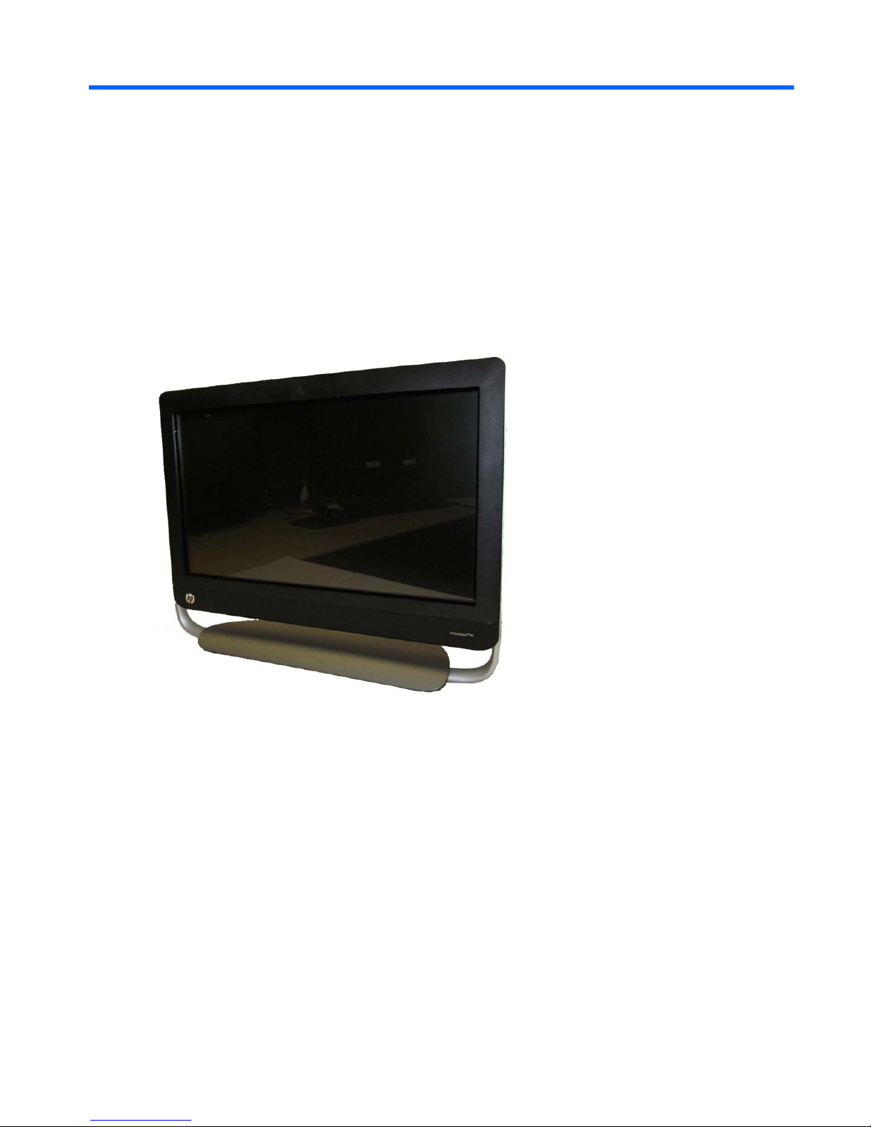
Figure 1-1 HP TouchSmart Elite 7320 All-in-One Business PC
The HP TouchSmart Elite 7320 All-In One Business PC offers the following features:
●
All-in-One form factor with 21.5” diagonal touch-enabled widescreen LED anti-glare display with
full HD, adjustable tilt stand, HD low-light webcam and stereo speakers
●
Intel® Core™ i3, Intel Core i5, Intel Core i7, Intel Pentium Dual Core
●
Intel H61 chipset
●
Operating systems:
◦
Genuine Windows 7 Professional 64
◦
Genuine Windows 7 Home Premium 64
◦
Redflag Linux
◦
FreeDOS
Overview 1

●
Graphics:
◦
Integrated: Intel HD Graphics
◦
Discrete: NVIDIA GeForce 5xx (1GB); NVIDIA GeForce GT 5xx (2GB); AMD Radeon HD
6450A (1GB); AMD Radeon HD 6550A (2GB)
NOTE: Discrete graphics not available in the Americas region.
●
Integrated Realtek RTL8171EH Gigabit Ethernet Controller
●
HP Wireless 802.11 b/g/n Mini Card (2x2)
●
HP Wireless 802.11b/g/n Mini Card (2x2) with Bluetooth Combo
●
(2) SODIMM slots, up to 8 GB DDR3 non-ECC SDRAM (2 X 4 GB)
●
Hard drives:
◦
250GB to 2TB SATA 6.0Gb/s (7200 rpm)
◦
1.5TB to 2TB SATA 6.0Gb/s (5400 rpm)
◦
250GB to 2TB SATA 3.0Gb/s (7200 rpm)
◦
1.5TB to 2TB SATA 3.0Gb/s (5400 rpm)
●
HP Slim Tray-load DVD Writer, HP Slim Tray-load Blu-ray Combo Writer
●
Mini PCIe x1 slot
●
(4) rear USB 2.0; (2) side USB 3.0; Stereo audio headphone jack; Stereo audio line out; Coaxial
cables for tuner; IR blaster; Power connector; RJ-45 Ethernet; 6-in-1 Media Card Reader
●
Integrated IDT 92HD91 with Beats Audio™ and high-performance stereo speakers
●
Power:
◦
External 150W for UMA graphics cards
◦
External 180W for MXM graphics cards
NOTE: Discrete graphics not available in the Americas region.
2 Chapter 1 Product Features
Front Components
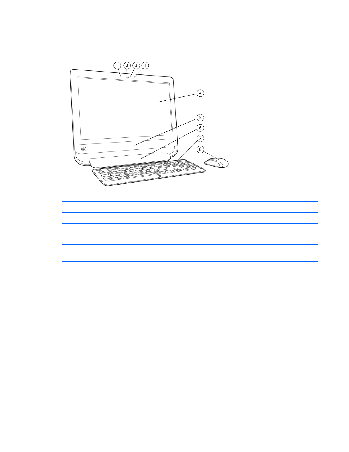
Figure 1-2 Front Components
Table 1-1 Front Components
Component Component
1 Dual microphone array 5 Stereo speakers
2 Fixed 2-MP HD low-light webcam 6 Adjustable tilt stand
3 Webcam LED indicator 7 HP Wireless Keyboard
4 21.5-inch touch-enabled diagonal widescreen LED
anti-glare display with full HD
8HP Wireless Mouse
Front Components 3
Side Components
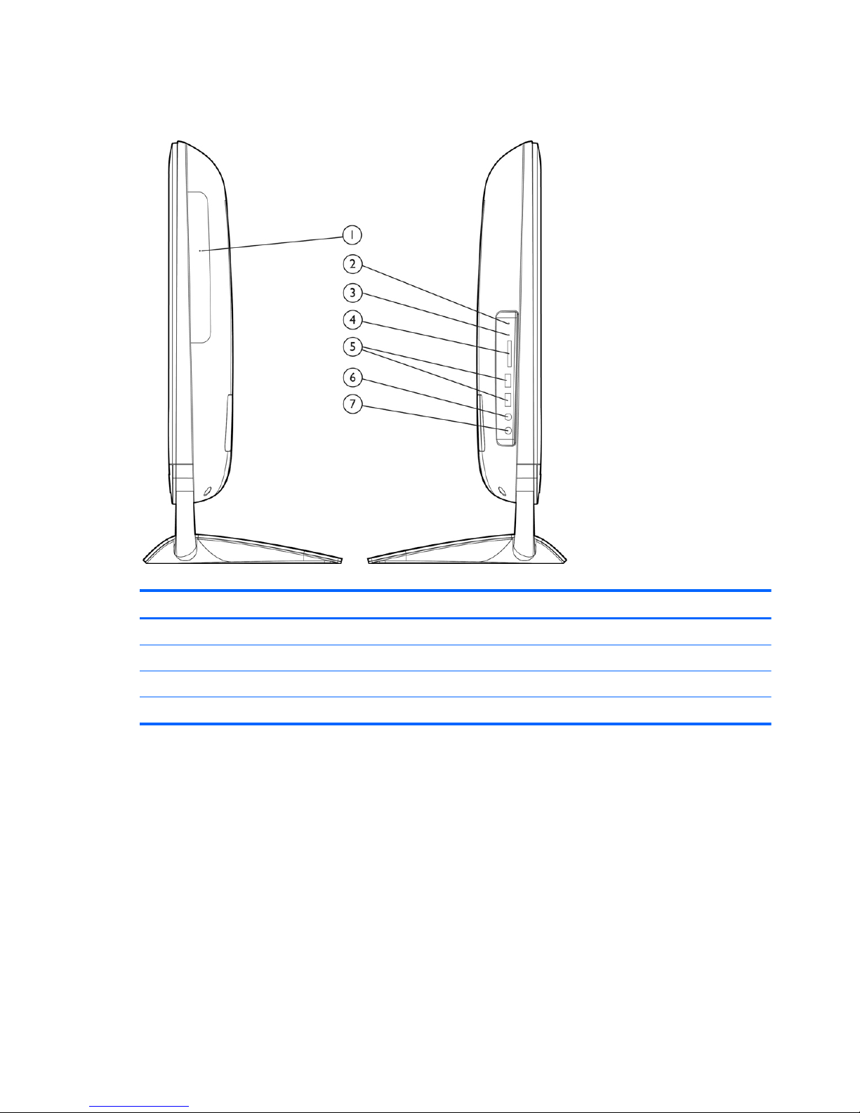
Figure 1-3 Side Components
Table 1-2 Side Components
Component Component
1 Optical Disk Drive 5 2 USB 2.0 ports
2 Hard Disk Drive LED Indicator 6 MIC Port
3 Media Card Reader LED Indicator 7 Headphone Port
4 6-in-1 Media Card Reader
4 Chapter 1 Product Features
Rear Components
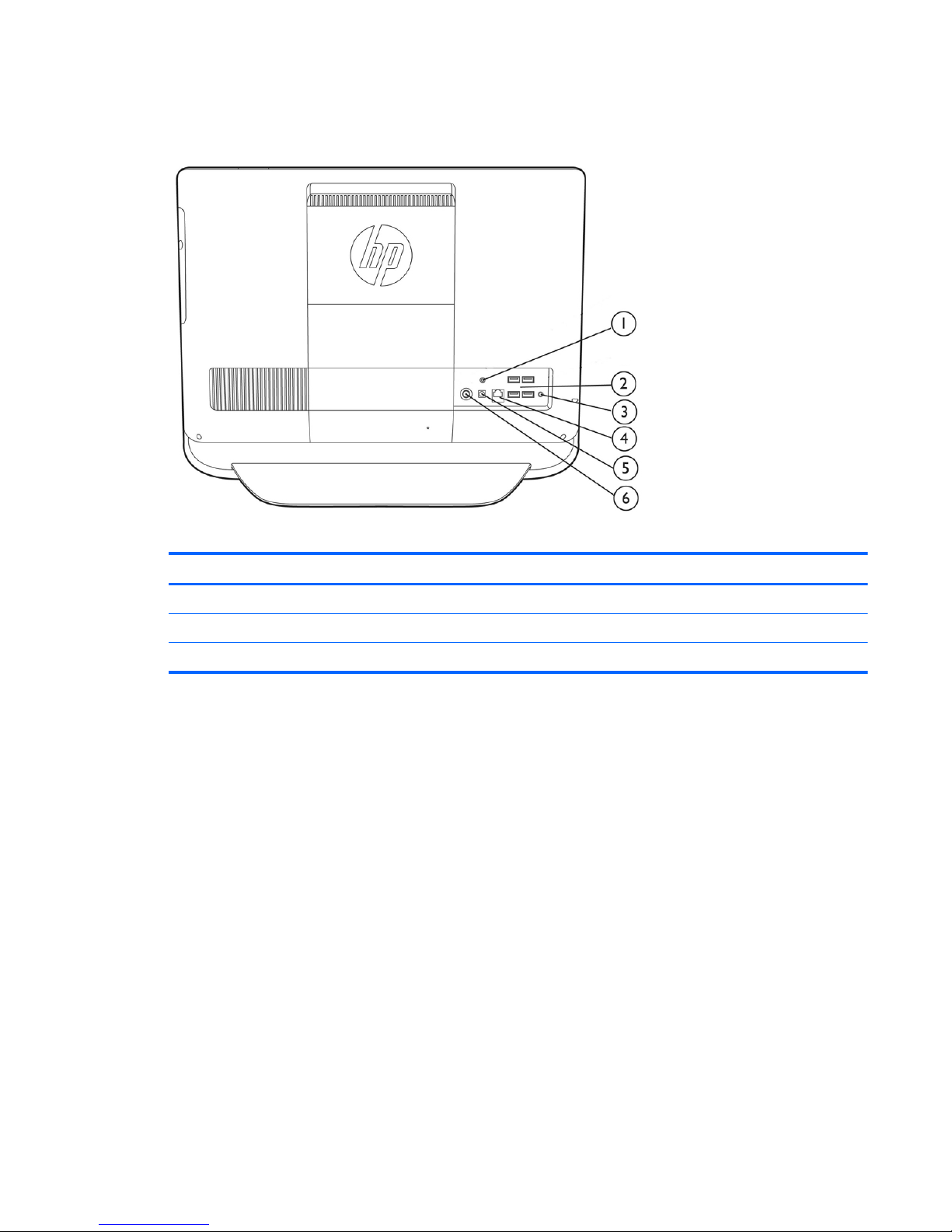
Figure 1-4 Rear Components
Table 1-3 Rear Components
Component Component
1 IR Emitter (Blaster) output 4 RJ-45/Ethernet
2 4 USB 2.0 ports 5 Power connector
3 Line out 6 TV coax in
Rear Components 5

2 Installing and Customizing the
Software
If your computer was not shipped with a Microsoft operating system, some portions of this
documentation do not apply. Additional information is available in online help after you install the
operating system.
NOTE: If the computer was shipped with Windows 7 loaded, you will be prompted to register the
computer with HP Total Care before installing the operating system. You will see a brief movie
followed by an online registration form. Fill out the form, click the Begin button, and follow the
instructions on the screen.
CAUTION: Do not add optional hardware or third-party devices to the computer until the operating
system is successfully installed. Doing so may cause errors and prevent the operating system from
installing properly.
NOTE: Be sure there is a 10.2-cm (4-inch) clearance at the back of the unit and above the monitor
to permit the required airflow.
Installing the Operating System
The first time you turn on the computer, the operating system is installed automatically. This process
takes about 5 to 10 minutes, depending on which operating system is being installed. Carefully read
and follow the instructions on the screen to complete the installation.
CAUTION: Once the automatic installation has begun, DO NOT TURN OFF THE COMPUTER
UNTIL THE PROCESS IS COMPLETE. Turning off the computer during the installation process may
damage the software that runs the computer or prevent its proper installation.
NOTE: If the computer shipped with more than one operating system language on the hard drive,
the installation process could take up to 60 minutes.
If your computer was not shipped with a Microsoft operating system, some portions of this
documentation do not apply. Additional information is available in online help after you install the
operating system.
Downloading Microsoft Windows Updates
1. To set up your Internet connection, click Start > Internet Explorer and follow the instructions on
the screen.
2. Once an Internet connection has been established, click the Start button.
6 Chapter 2 Installing and Customizing the Software

3. Select the All Programs menu.
4. Click on the Windows Update link.
The Windows Update screen appears. Click view available updates and make sure all critical
updates are selected. Click the Install button and follow the instructions on the screen.
It is recommended that you install all of the critical updates and service packs.
5. After the updates have been installed, Windows will prompt you to reboot the machine. Be sure
to save any files or documents that you may have open before rebooting. Then select Yes to
reboot the machine.
Installing or Upgrading Device Drivers (Windows
systems)
When installing optional hardware devices after the operating system installation is complete, you
must also install the drivers for each of the devices.
If prompted for the i386 directory, replace the path specification with C:\i386, or use the Browse
button in the dialog box to locate the i386 folder. This action points the operating system to the
appropriate drivers.
Obtain the latest support software, including support software for the operating system from
http://www.hp.com/support. Select your country and language, select Download drivers and
software (and firmware), enter the model number of the computer, and press Enter.
Accessing Disk Image (ISO) Files
There are disk image files (ISO files) included on your PC that contain the installation software for
additional software. These CD image files are located in the folder C:\SWSetup\ISOs. Each .iso file
can be burned to CD media to create an installation CD. It is recommended that these disks be
created and the software installed in order to get the most from your PC. The software and image file
names are:
● Corel WinDVD SD and BD – installation software for WinDVD – used to play DVD movies
● HP Insight Diagnostics OR Vision Diagnostics – software to perform diagnostic activities on your
PC
Protecting the Software
To protect the software from loss or damage, keep a backup copy of all system software,
applications, and related files stored on the hard drive. Refer to the operating system or backup utility
documentation for instructions on making backup copies of your data files.
Installing or Upgrading Device Drivers (Windows systems) 7

3 Computer Setup (F10) Utility
Computer Setup (F10) Utilities
Use Computer Setup (F10) Utility to do the following:
●
Change factory default settings.
●
Set the system date and time.
● Set, view, change, or verify the system configuration, including settings for processor, graphics,
memory, audio, storage, communications, and input devices.
●
Modify the boot order of bootable devices such as hard drives, optical drives, or USB flash
media devices.
●
Enable Quick Boot, which is faster than Full Boot but does not run all of the diagnostic tests run
during a Full Boot. You can set the system to:
❑
always Quick Boot (default);
❑
periodically Full Boot (from every 1 to 30 days); or
❑
always Full Boot.
● Select Post Messages Enabled or Disabled to change the display status of Power-On Self-Test
(POST) messages. Post Messages Disabled suppresses most POST messages, such as
memory count, product name, and other non-error text messages. If a POST error occurs, the
error is displayed regardless of the mode selected. To manually switch to Post Messages
Enabled during POST, press any key (except F1 through F12).
●
Establish an Ownership Tag, the text of which is displayed each time the system is turned on or
restarted.
●
Enter the Asset Tag or property identification number assigned by the company to this computer.
●
Enable the power-on password prompt during system restarts (warm boots) as well as during
power-on.
●
Establish a setup password that controls access to the Computer Setup (F10) Utility and the
settings described in this section.
●
Secure integrated I/O functionality, including USB, audio, or embedded NIC, so that they cannot
be used until they are unsecured.
●
Enable or disable removable media boot ability.
8 Chapter 3 Computer Setup (F10) Utility

●
Solve system configuration errors detected but not automatically fixed during the Power-On SelfTest (POST).
●
Replicate the system setup by saving system configuration information on a USB flash drive and
restoring it on one or more computers.
●
Execute self-tests on a specified ATA hard drive (when supported by drive).
●
Enable or disable DriveLock security (when supported by drive).
Using Computer Setup (F10) Utilities
Computer Setup can be accessed only by turning the computer on or restarting the system.
To access the Computer Setup Utilities menu, complete the following steps:
1. Turn on or restart the computer.
2. Press Esc while the “Press the ESC key for Startup Menu” message is displayed at the bottom
of the screen.
NOTE: If you do not press Esc at the appropriate time, you must restart the computer and
again press Esc when the monitor light turns green to access the utility.
3. Press F10 to enter Computer Setup.
4. A choice of five headings appears in the Computer Setup Utilities menu: File, Storage, Security,
Power, and Advanced.
5. Use the arrow (left and right) keys to select the appropriate heading. Use the arrow (up and
down) keys to select the option you want, then press Enter. To return to the Computer Setup
Utilities menu, press Esc.
6. To apply and save changes, select File > Save Changes and Exit.
●
If you have made changes that you do not want applied, select Ignore Changes and Exit.
●
To reset to factory settings or previously saved default settings (some models), select
Apply Defaults and Exit. This option will restore the original factory system defaults.
CAUTION: Do NOT turn the computer power OFF while the BIOS is saving the Computer Setup
(F10) changes because the CMOS could become corrupted. It is safe to turn off the computer only
after exiting the F10 Setup screen.
Computer Setup (F10) Utilities 9

Computer Setup—File
NOTE: Support for specific Computer Setup options may vary depending on the hardware
configuration.
Table 3-1 Computer Setup—File
Option Description
System Information Lists:
●
Product name
●
SKU number (some models)
● Processor type/speed/stepping
● Cache size (L1/L2/L3)
●
Installed memory size/speed, number of channels (single or dual) (if applicable)
●
Integrated MAC address for embedded, enabled NIC (if applicable)
● System BIOS (includes family name and version)
●
Chassis serial number
●
Asset Tracking Number
About Displays copyright notice.
Set Time and Date Allows you to set system time and date.
Apply Defaults and
Exit
Applies the currently selected default settings and clears any established passwords.
Ignore Changes
and Exit
Exits Computer Setup without applying or saving any changes.
Save Changes and
Exit
Saves changes to system configuration or default settings and exits Computer Setup.
10 Chapter 3 Computer Setup (F10) Utility

Computer Setup—Storage
NOTE: Support for specific Computer Setup options may vary depending on the hardware
configuration.
Table 3-2 Computer Setup—Storage
Option Description
Device Configuration Lists all installed BIOS-controlled storage devices.
When a device is selected, detailed information and options are displayed. The following options
may be presented:
Hard Disk: Size, model, firmware version, serial number.
Emulation type has the following choices:
● None (prevents BIOS data accesses and disables it as a boot device)
●
Hard Disk (treated as a hard disk)
CD-ROM: Model, firmware version, serial number.
Storage Options SATA Emulation
Allows you to choose how the SATA controller and devices are accessed by the operating
system. There are two supported options: IDE and AHCI.
The default is set based on the Feature Byte code stored in the SMBIOS Type11/Feature Byte
string as follows:
Feature Byte Default
FBC_SATA_RAID RAID
FBC_SATA_AHCI AHCI
FBC_SATA_IDE IDE
Otherwise (none found) Platform-dependent - to be implemented by BIOS Integrator
IDE - This is the most backwards-compatible setting of the three options. Operating systems
usually do not require additional driver support in IDE mode.
AHCI (default option) - Allows operating systems with AHCI device drivers loaded to take
advantage of more advanced features of the SATA controller.
Computer Setup (F10) Utilities 11

Table 3-2 Computer Setup—Storage (continued)
DPS Self-Test Allows you to execute self-tests on ATA hard drives capable of performing the Drive Protection
System (DPS) self-tests.
NOTE: This selection will only appear when at least one drive capable of performing the DPS
self-tests is attached to the system.
Boot Order Allows you to:
●
Specify the order in which EFI boot sources (such as a internal hard drive, USB hard drive,
USB optical drive, or internal optical drive) are checked for a bootable operating system
image. Each device on the list may be individually excluded from or included for
consideration as a bootable operating system source.
EFI boot sources always have precedence over legacy boot sources.
● Specify the order in which legacy boot sources (such as a network interface card, internal
hard drive, USB optical drive, or internal optical drive) are checked for a bootable operating
system image. Each device on the list may be individually excluded from or included for
consideration as a bootable operating system source.
●
Specify the order of attached hard drives. The first hard drive in the order will have priority in
the boot sequence and will be recognized as drive C (if any devices are attached).
NOTE: You can use F5 to disable individual boot items, as well as disable EFI boot and/or
legacy boot.
NOTE: MS-DOS drive lettering assignments may not apply after a non-MS-DOS operating
system has started.
Shortcut to Temporarily Override Boot Order
To boot one time from a device other than the default device specified in Boot Order, restart the
computer and press Esc (to access the boot menu) and then F9 (Boot Order), or only F9 (skipping
the boot menu) when the monitor light turns green. After POST is completed, a list of bootable
devices is displayed. Use the arrow keys to select the preferred bootable device and press Enter.
The computer then boots from the selected non-default device for this one time.
12 Chapter 3 Computer Setup (F10) Utility

Computer Setup—Security
NOTE: Support for specific Computer Setup options may vary depending on the hardware
configuration.
Table 3-3 Computer Setup—Security
Option Description
Setup Password Allows you to set and enable a setup (administrator) password.
NOTE: If the setup password is set, it is required to change Computer Setup options, flash the
ROM, and make changes to certain plug and play settings under Windows.
See the Desktop Management Guide for more information.
Power-On Password Allows you to set and enable a power-on password. The power-on password prompt appears
after a power cycle. If the user does not enter the correct power-on password, the unit will not
boot.
NOTE: This password does not appear on warm boots , such as Ctrl+Alt+Delete or Restart
from Windows, unless enabled in Password Options (see below).
See the Desktop Management Guide for more information.
Password Options
(Appears only if a
power-on password or
setup password is set.)
Allows you to:
● Lock legacy resources (appears if a setup password is set). Default is enable.
●
Enable/Disable Setup Browse Mode (appears if a setup password is set) (allows viewing, but
not changing, the F10 Setup Options without entering setup password). Default is enable.
●
Specify whether the password is required for warm boot (Ctrl+Alt+Delete) (appears if a
power-on password is set). Default is enable.
●
Enable/disable network server mode (appears if a power-on password is set). Default is
disable.
Device Security Allows you to set Device Available/Device Hidden for:
● Embedded Security Device (some models)
●
System Audio
●
Network Controller (some models)
● SATA connectors/devices
USB Security Allows you to enable or disable groups of USB ports or individual USB ports. Default is device
available.
● Front USB Ports
●
Rear USB Ports
●
internal USB Ports
Slot Security Allows you to disable or enable the PCI, PCI Express, and MiniCard slots (as applicable). Default
is enable.
Network Boot Enables/disables the computer’s ability to boot from an operating system installed on a network
server. (Feature available on NIC models only; the network controller must be either a PCI
Express expansion card or embedded on the system board.) Default is enable.
Computer Setup (F10) Utilities 13

Table 3-3 Computer Setup—Security (continued)
System IDs Allows you to view:
● Product Name
● Serial number
● Universal Unique Identifier (UUID) number. The UUID can only be updated if the current
chassis serial number is invalid. (These ID numbers are normally set in the factory and are
used to uniquely identify the system.)
●
SKU Number
●
Family Name
● Asset tag (18-byte identifier), a property identification number assigned by the company to
the computer.
● Feature Byte
● Build ID
● Keyboard locale setting for System ID entry
System Security
(some models: these
options are hardware
dependent)
Data Execution Prevention (enable/disable) - Helps prevent operating system security breaches.
Default is enabled.
Virtualization Technology (VTx/VTd)(some models) (enable/disable) - Controls the virtualization
features of the processor and DMA remapping features of the chipset. Changing this setting
requires turning the computer off and then back on. Default is disabled.
PAVP (Models with Blu-ray drives) (disabled/min/max) - PAVP enables the Protected Audio Video
Path in the Chipset. This may allow viewing of some protected high definition content that would
otherwise be prohibited from playback. Selecting Max will assign 96 Megabytes of system
memory exclusively to PAVP.
Intel TXT (LT) Support (some models) (enable/disable) - Controls the underlying processor and
chipset features needed to support a virtual appliance. Changing this setting requires turning the
computer off and then back on. Default is disabled. To enable this feature you must enable the
following features:
●
Embedded Security Device Support
●
Virtualization Technology
● Virtualization Technology Directed I/O
14 Chapter 3 Computer Setup (F10) Utility

Table 3-3 Computer Setup—Security (continued)
Embedded Security Device (some models) (enable/disable) - Permits activation and deactivation
of the Embedded Security Device. Changing this setting requires turning the computer off and
then back on.
NOTE: To configure the Embedded Security Device, a Setup password must be set.
● Reset to Factory Settings (some models) (Do not reset/Reset) - Resetting to factory defaults
will erase all security keys. Changing this setting requires turning the computer off and then
back on. Default is Do not reset.
CAUTION: The embedded security device is a critical component of many security
schemes. Erasing the security keys will prevent access to data protected by the Embedded
Security Device. Choosing Reset to Factory Settings may result in significant data loss.
OS management of Embedded Security Device (some models) (enable/disable) - This option
allows the user to limit operating system control of the Embedded Security Device. Changing this
setting requires turning the computer off and then back on. This option allows the user to limit OS
control of the Embedded Security Device. Default is enable.
●
Reset of Embedded Security Device through OS (some models) (enable/disable) - This
option allows the user to limit the operating system ability to request a Reset to Factory
Settings of the Embedded Security Device. Changing this setting requires turning the
computer off and then back on. Default is disable.
NOTE: To enable this option, a Setup password must be set.
DriveLock Security Allows you to assign or modify a master or user password for hard drives. When this feature is
enabled, the user is prompted to provide one of the DriveLock passwords during POST. If neither
is successfully entered, the hard drive will remain inaccessible until one of the passwords is
successfully provided during a subsequent cold-boot sequence.
NOTE: This selection will only appear when at least one drive that supports the DriveLock
feature is attached to the system.
Computer Setup (F10) Utilities 15

Computer Setup—Power
NOTE: Support for specific Computer Setup options may vary depending on the hardware
configuration.
Table 3-4 Computer Setup—Power
Option Description
Hardware Power
Management
SATA Power Management – Enables or disables SATA bus and/or device power management.
Default is enabled.
S5 Maximum Power Savings – Turns off power to all nonessential hardware when system is off to
meet EUP Lot 6 requirement of less than 1 Watt power usage. Default is enabled.
S5 Wake on LAN (enable/disable).
●
To disable Wake on LAN during the off state (S5), use the arrow (left and right) keys to
select the Advanced > Device Options menu and set the S5 Wake on LAN feature to
Disable. This obtains the lowest power consumption available on the computer during S5. It
does not affect the ability of the computer to Wake on LAN from suspend or hibernation, but
will prevent it from waking from S5 via the network. It does not affect operation of the
network connection while the computer is on.
●
If a network connection is not required, completely disable the network controller (NIC) by
using the arrow (left and right) keys to select the Security > Device Security menu. Set the
Network Controller option to Device Hidden. This prevents the network controller from being
used by the operating system and reduces the power used by the computer in S5.
Thermal Displays the CPU fan speed (RPMs).
16 Chapter 3 Computer Setup (F10) Utility

Computer Setup—Advanced
NOTE: Support for specific Computer Setup options may vary depending on the hardware
configuration.
Table 3-5 Computer Setup—Advanced
Option Heading
Power-On Options Allows you to set:
●
POST messages (enable/disable). Default is disabled.
●
After Power Loss (off/on/previous state). Default is Power off. Setting this option to:
◦ Power off—causes the computer to remain powered off when power is restored.
◦ Power on—causes the computer to power on automatically as soon as power is
restored.
◦ Previous state—causes the computer to power on automatically as soon as power is
restored, if it was on when power was lost.
NOTE: If you turn off power to the computer using the switch on a power strip, you will not be
able to use the suspend/sleep feature or the Remote Management features.
●
POST Delay (in seconds). Enabling this feature will add a user-specified delay to the POST
process. This delay is sometimes needed for hard disks on some PCI cards that spin up very
slowly, so slowly that they are not ready to boot by the time POST is finished. The POST
delay also gives you more time to select F10 to enter Computer (F10) Setup. Default is
None.
BIOS Power-On Allows you to set the computer to turn on automatically at a time you specify.
Bus Options On some models, allows you to enable or disable:
●
PCI SERR# Generation. Default is enable.
●
PCI VGA Palette Snooping, which sets the VGA palette snooping bit in PCI configuration
space; only needed when more than one graphics controller is installed. Default is disable.
Device Options Allows you to set:
● Num Lock State at Power-On (off/on). Default is off.
●
Multi-Processor (enable/disable). Use this option to disable multi-processor support under
the OS. Default is enabled.
●
Hyper-threading (enable/disable) (some models). Use this option to disable processor
hyperthreading.
●
Integrated Video (enable/disable). Use this option to disable the integrated video controller
when another video controller is present in the system. Default is enabled.
●
NIC PXE Option ROM Download (PXE, iSCSI, disabled). The BIOS contains an embedded
NIC option ROM to allow the unit to boot through the network to a PXE server. This is
typically used to download a corporate image to a hard drive. The NIC option ROM takes up
memory space below 1MB commonly referred to as DOS Compatibility Hole (DCH) space.
This space is limited. This F10 option will allow users to disable the downloading of this
embedded NIC option ROM thus giving more DCH space for additional PCI cards which may
need option ROM space. The default will be to have the NIC option-ROM-enabled. Default is
PXE.
Computer Setup (F10) Utilities 17

4 Serial ATA (SATA) Drive Guidelines
and Features
NOTE: HP only supports the use of SATA hard drives on these models of computer. No Parallel
ATA (PATA) drives are supported.
SATA Hard Drives
Serial ATA Hard Drive Characteristics
Number of pins/conductors in data cable 7/7
Number of pins in power cable 15
Maximum data cable length 39.37 in (100 cm)
Data interface voltage differential 400-700 mV
Drive voltages 3.3 V, 5 V, 12 V
Jumpers for configuring drive N/A
Data transfer rate 3.0 Gb/s
SATA Hard Drive Cables
SATA Data Cable
Always use an HP approved SATA 3.0 Gb/s cable as it is fully backwards compatible with the SATA
1.5 Gb/s drives.
Current HP desktop products ship with SATA 3.0 Gb/s hard drives.
SATA data cables are susceptible to damage if overflexed. Never crease a SATA data cable and
never bend it tighter than a 30 mm (1.18 in) radius.
The SATA data cable is a thin, 7-pin cable designed to transmit data for only a single drive.
18 Chapter 4 Serial ATA (SATA) Drive Guidelines and Features

SMART ATA Drives
The Self Monitoring Analysis and Recording Technology (SMART) ATA drives for the HP Personal
Computers have built-in drive failure prediction that warns the user or network administrator of an
impending failure or crash of the hard drive. The SMART drive tracks fault prediction and failure
indication parameters such as reallocated sector count, spin retry count, and calibration retry count. If
the drive determines that a failure is imminent, it generates a fault alert.
Hard Drive Capacities
The combination of the file system and the operating system used in the computer determines the
maximum usable size of a drive partition. A drive partition is the largest segment of a drive that may
be properly accessed by the operating system. A single hard drive may therefore be subdivided into a
number of unique drive partitions in order to make use of all of its space.
Because of the differences in the way that drive sizes are calculated, the size reported by the
operating system may differ from that marked on the hard drive or listed in the computer specification.
Drive size calculations by drive manufacturers are bytes to the base 10 while calculations by
Microsoft are bytes to the base 2.
Drive/Partition Capacity Limits
Maximum Size
File System Controller Type Operating System Partition Drive
FAT 32 ATA Windows 7 32 GB 2 TB
NTFS ATA Windows 7 2 TB 2 TB
SMART ATA Drives 19

5 Routine Care and Disassembly
Preparation
This chapter provides general service information for the computer. Adherence to the procedures and
precautions described in this chapter is essential for proper service.
CAUTION: When the computer is plugged into an AC power source, voltage is always applied to
the system board. You must disconnect the power cord from the power source before opening the
computer to prevent system board or component damage.
Electrostatic Discharge Information
A sudden discharge of static electricity from your finger or other conductor can destroy static-sensitive
devices or microcircuitry. Often the spark is neither felt nor heard, but damage occurs. An electronic
device exposed to electrostatic discharge (ESD) may not appear to be affected at all and can work
perfectly throughout a normal cycle. The device may function normally for a while, but it has been
degraded in the internal layers, reducing its life expectancy.
Networks built into many integrated circuits provide some protection, but in many cases, the
discharge contains enough power to alter device parameters or melt silicon junctions.
Generating Static
The following table shows that:
●
Different activities generate different amounts of static electricity.
●
Static electricity increases as humidity decreases.
Relative Humidity
Event 55% 40% 10%
Walking across carpet
Walking across vinyl floor
Motions of bench worker
Removing DIPs* from plastic tube
7,500 V
3,000 V
400 V
400 V
15,000 V
5,000 V
800 V
700 V
35,000 V
12,000 V
6,000 V
2,000 V
20 Chapter 5 Routine Care and Disassembly Preparation

Removing DIPs* from vinyl tray
Removing DIPs* from Styrofoam
Removing bubble pack from PCB
Packing PCBs in foam-lined box
2,000 V
3,500 V
7,000 V
5,000 V
4,000 V
5,000 V
20,000 V
11,000 V
11,500 V
14,500 V
26,500 V
21,000 V
*These are then multi-packaged inside plastic tubes, trays, or Styrofoam.
NOTE: 700 volts can degrade a product.
Preventing Electrostatic Damage to Equipment
Many electronic components are sensitive to ESD. Circuitry design and structure determine the
degree of sensitivity. The following packaging and grounding precautions are necessary to prevent
damage to electric components and accessories.
●
To avoid hand contact, transport products in static-safe containers such as tubes, bags, or
boxes.
●
Protect all electrostatic parts and assemblies with conductive or approved containers or
packaging.
●
Keep electrostatic sensitive parts in their containers until they arrive at static-free stations.
●
Place items on a grounded surface before removing them from their container.
●
Always be properly grounded when touching a sensitive component or assembly.
●
Avoid contact with pins, leads, or circuitry.
●
Place reusable electrostatic-sensitive parts from assemblies in protective packaging or
conductive foam.
Personal Grounding Methods and Equipment
Use the following equipment to prevent static electricity damage to equipment:
● Wrist straps are flexible straps with a maximum of one-megohm ± 10% resistance in the ground
cords. To provide proper ground, a strap must be worn snug against bare skin. The ground cord
must be connected and fit snugly into the banana plug connector on the grounding mat or
workstation.
●
Heel straps/Toe straps/Boot straps can be used at standing workstations and are compatible
with most types of shoes or boots. On conductive floors or dissipative floor mats, use them on
both feet with a maximum of one-megohm ± 10% resistance between the operator and ground.
Static Shielding Protection Levels
Method Voltage
Antistatic plastic
Carbon-loaded plastic
Metallized laminate
1,500
7,500
15,000
Electrostatic Discharge Information 21

Grounding the Work Area
To prevent static damage at the work area, use the following precautions:
● Cover the work surface with approved static-dissipative material. Provide a wrist strap connected
to the work surface and properly grounded tools and equipment.
● Use static-dissipative mats, foot straps, or air ionizers to give added protection.
● Handle electrostatic sensitive components, parts, and assemblies by the case or PCB laminate.
Handle them only at static-free work areas.
● Turn off power and input signals before inserting and removing connectors or test equipment.
● Use fixtures made of static-safe materials when fixtures must directly contact dissipative
surfaces.
● Keep work area free of nonconductive materials such as ordinary plastic assembly aids and
Styrofoam.
●
Use field service tools, such as cutters, screwdrivers, and vacuums, that are conductive.
Recommended Materials and Equipment
Materials and equipment that are recommended for use in preventing static electricity include:
●
Antistatic tape
●
Antistatic smocks, aprons, or sleeve protectors
●
Conductive bins and other assembly or soldering aids
●
Conductive foam
●
Conductive tabletop workstations with ground cord of one-megohm +/- 10% resistance
●
Static-dissipative table or floor mats with hard tie to ground
●
Field service kits
●
Static awareness labels
●
Wrist straps and footwear straps providing one-megohm +/- 10% resistance
●
Material handling packages
●
Conductive plastic bags
●
Conductive plastic tubes
●
Conductive tote boxes
●
Opaque shielding bags
●
Transparent metallized shielding bags
●
Transparent shielding tubes
22 Chapter 5 Routine Care and Disassembly Preparation
 Loading...