

Page 1

Maintenance and Service Guide
HP TouchSmart 9100 Business PC
Page 2

© Copyright 2009 Hewlett-Packard
Development Company, L.P. The
information contained herein is subject to
change without notice.
Microsoft and Windows are trademarks of
Microsoft Corporation in the U.S. and other
countries.
The only warranties for HP products and
services are set forth in the express
warranty statements accompanying such
products and services. Nothing herein
should be construed as constituting an
additional warranty. HP shall not be liable
for technical or editorial errors or omissions
contained herein.
This document contains proprietary
information that is protected by copyright.
No part of this document may be
photocopied, reproduced, or translated to
another language without the prior written
consent of Hewlett-Packard Company.
Maintenance and Service Guide
First Edition (December 2009)
Document Part Number: 602766-001
Page 3

About This Book
WARNING! Text set off in this manner indicates that failure to follow directions could result in bodily
harm or loss of life.
CAUTION: Text set off in this manner indicates that failure to follow directions could result in
damage to equipment or loss of information.
NOTE: Text set off in this manner provides important supplemental information.
iii
Page 4

iv About This Book
Page 5

Table of contents
1 Product Description ........................................................................................................................................ 1
2 Components .................................................................................................................................................... 2
Front and right side .............................................................................................................................. 2
Lower left-side components ................................................................................................................. 4
Rear components ................................................................................................................................. 5
Activity LED indicator lights .................................................................................................................. 6
Computer stand .................................................................................................................................... 7
3 Spare Parts ...................................................................................................................................................... 8
Processors and system board .............................................................................................................. 8
Drives ................................................................................................................................................... 8
Memory ................................................................................................................................................ 8
Misc Boards .......................................................................................................................................... 9
Power Adapters .................................................................................................................................... 9
Keyboards and Mice ............................................................................................................................. 9
Misc Parts ........................................................................................................................................... 10
4 Removal and Replacement Procedures ..................................................................................................... 11
Preparing to disassemble the HP TouchSmart PC ............................................................................ 11
Hard drive/memory cover ................................................................................................................... 12
I/O cover ............................................................................................................................................. 13
Feet .................................................................................................................................................... 14
Stand .................................................................................................................................................. 15
Adding Memory .................................................................................................................................. 16
Before you begin ................................................................................................................ 16
Removing a memory module ............................................................................................. 16
Removing the hard drive .................................................................................................................... 19
Back cover .......................................................................................................................................... 20
Graphics card ..................................................................................................................................... 22
WLAN module .................................................................................................................................... 24
TV tuner module ................................................................................................................................. 26
System board ..................................................................................................................................... 29
v
Page 6

Processor ........................................................................................................................................... 31
Bluetooth module ............................................................................................................................... 33
Optical drive ....................................................................................................................................... 35
Synchronizing the wireless keyboard or mouse ................................................................................. 36
Installing a Security Lock .................................................................................................................... 38
5 Computer Setup (F10) Utility ....................................................................................................................... 39
Computer Setup (F10) Utilities ........................................................................................................... 39
Using Computer Setup (F10) Utilities ................................................................................ 39
Computer Setup—Main ..................................................................................................... 40
Computer Setup—Advanced ............................................................................................. 41
Computer Setup—Power ................................................................................................... 42
Computer Setup—Boot ...................................................................................................... 43
Computer Setup—Exit ....................................................................................................... 44
BIOS updates ..................................................................................................................................... 44
6 Software Troubleshooting ........................................................................................................................... 45
Software Repair Overview .................................................................................................................. 45
Updating Drivers ................................................................................................................................. 45
Microsoft System Restore .................................................................................................................. 46
Software Program and Hardware Driver Reinstallation ...................................................................... 46
Creating data backup discs ................................................................................................................ 48
Clearing CMOS .................................................................................................................................. 48
Clearing BIOS passwords .................................................................................................................. 48
Power-On Self Test (POST) ............................................................................................................... 49
Troubleshooting .................................................................................................................................. 50
Determining Whether Your System Is 64-bit or 32-bit ........................................................................ 50
7 System Recovery .......................................................................................................................................... 51
Creating Recovery Discs .................................................................................................................... 51
Choosing Recovery Discs .................................................................................................................. 51
System Recovery Options .................................................................................................................. 52
System recovery from the Windows 7 Start menu ............................................................. 52
System recovery at system startup .................................................................................... 53
Starting system recovery from recovery discs ................................................................... 53
Index ................................................................................................................................................................... 55
vi
Page 7

1 Product Description
The HP TouchSmart 9100 Business PC transforms the PC experience with its All-in-One form factor
and touch-enabled features. The PC can be used as an everyday desktop, but is better suited to
reaching customers with interactive touch-enabled applications.
The HP TouchSmart 9100 features a certified Windows 7 multi-touch touchscreen that enables users
to interact with the PC using gestures and manipulation. Users can optimize the potential of the HP
TouchSmart 9100 with third-party touch applications to improve workflow and information delivery.
The sleek, space-saving, All-in-One design of the PC has the following built-in features:
58.42 cm (23-inch) diagonal full HD widescreen display, multi-touch enabled
●
Integrated VGA camera
●
Speakers
●
WLAN and Bluetooth connectivity
●
The HP TouchSmart 9100 uses the All-in-One form factor and allows businesses to reach their
customers in a new engaging user-friendly way. The PC focuses on providing real-time information
and features video-conferencing capabilities.
The HP TouchSmart 9100 is designed for use in:
Conference rooms
●
High traffic, customer-facing areas
●
Kiosks
●
Education and training
●
1
Page 8
2 Components
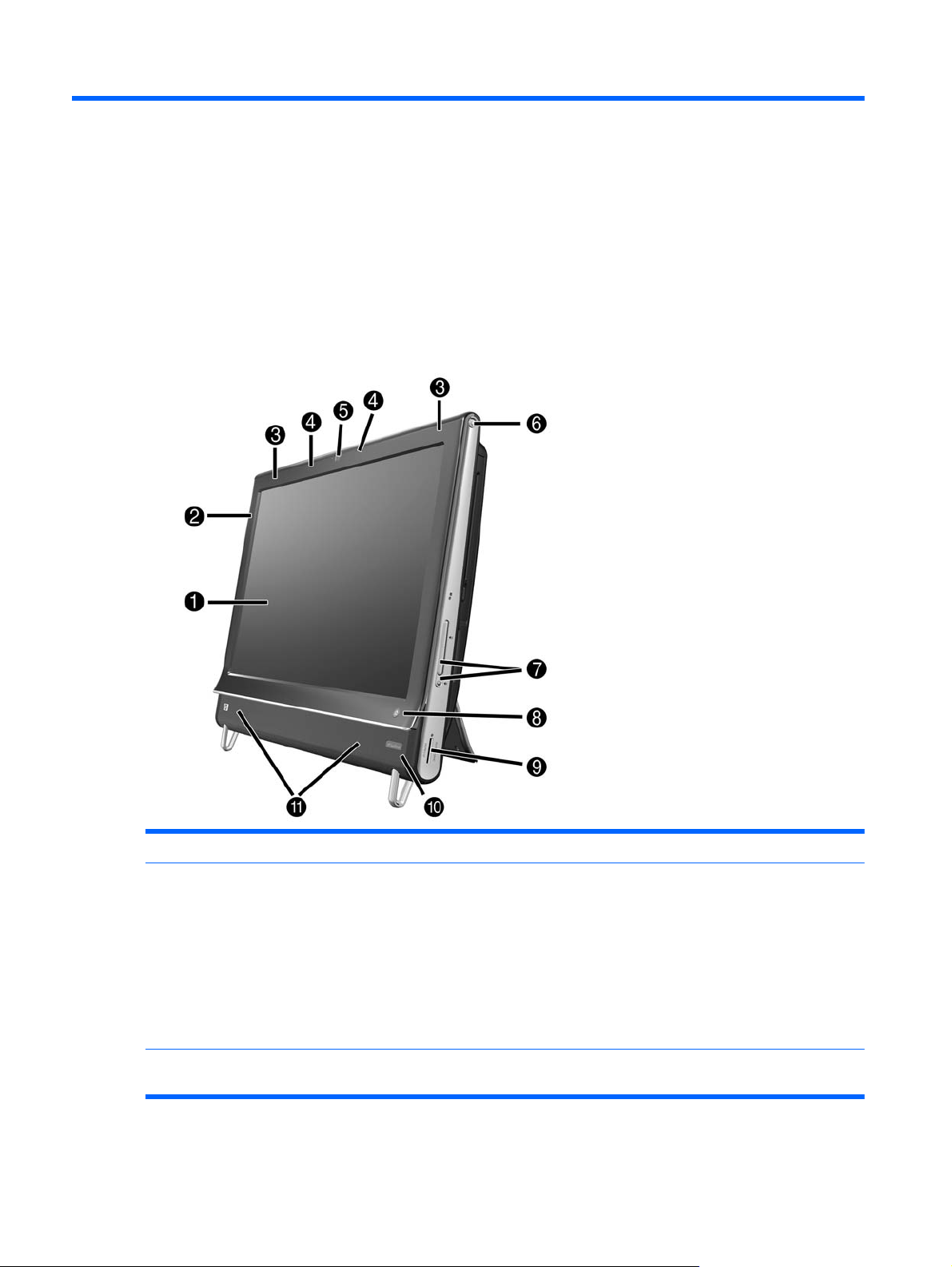
Front and right side
Item Item Component
1 LCD display optimized for
Touch
2 Bluetooth (select models
only)
2 Chapter 2 Components
State-of-the-art 58.4-cm (23-in) diagonal widescreen high-definition display with
HP BrightView technology.* HP BrightView technology improves the contrast and
clarity of your display. In addition, it boasts a high resolution of 1920 x 1080 and a
fast response time of 5 ms.**
* High definition (HD) content is required to view HD images. Most current DVDs
do not provide HD images.
**All specifications represent the typical specifications provided by HewlettPackard’s component manufacturers; actual performance may vary either higher
or lower.
Use Bluetooth to connect to Bluetooth-enabled devices. The diagram shows the
internal location of Bluetooth (not visible externally).
Page 9

3 Built-in wireless LAN
(select models only)
Use the built-in wireless LAN to connect to the Internet through your existing
wireless network. The diagram shows the internal location of the wireless LAN
(top left and right, not visible externally).
The wireless LAN supports IEEE 802.11 b/g/n.
4 Microphone array Use the built-in digital microphones to record sound for your webcam videos, and
5 Webcam Create videos and snapshots that you can view, send by e-mail, and upload to
6 Power/Sleep button Press the Power/Sleep button to turn on your HP TouchSmart 9100 Business PC,
7 Volume, and mute
controls
8 HP TouchSmart button
HP TouchSmart button
to use instant messenger or chat software to have video chats online. The
microphone is designed to provide a cleaner sound by filtering out ambient noise
in your environment. It is designed to record from a distance of up to one-half
meter (2 feet) away from the computer.
video sharing sites. Use the built-in webcam and microphone array to have video
chats with friends and family.*
To adjust the viewing angle of the webcam shot, tilt the screen, or use the adjust
lever immediately behind the webcam. You can also choose how tightly you want
to crop the view of the camera, creating a close-up view of your face or including
more of the background.
* Internet access required.
or to put it into Sleep mode.
To turn off your computer, tap the Start button, and then select Shut Down. Or
tap the arrow next to the Shut Down button to switch users, log off, lock, restart,
or sleep.
Adjust the sound level up or down, or mute.
Turn your HP TouchSmart 9100 Business PC on and open your HP TouchSmart
software. Or, if the computer is already turned on, press the button to open the HP
TouchSmart software for quick access to your music, photos, videos, or the Web.
The HP TouchSmart button cannot turn the computer off.
9 Memory card reader Use the built-in memory card reader to easily access photos and other files
directly from a memory card.
Supported formats include xD media (xD), Secure Digital (SD), Secure Digital
High Capacity (SDHC), MultiMediaCard (MMC), Memory Stick (MS), and Memory
Stick Pro (MS-Pro) memory cards.
Your memory card reader also supports adapters for the following memory cards:
Mini SD, RS MMC, Micro SD, MS-Duo, and MS Duo Pro.
10 IR receiver window
(select models only)
11 Internal Speakers Use the built-in, high-quality stereo speakers for a powerful media experience
12 Slot-loading CD/DVD
drive (located on back
side panel)CD/DVD slot
13 B-CAS card slot (select
models only)
Infrared (IR) receiver window, located on the lower-right side of the computer.
Allows for use with a remote control.
when listening to music, or when watching your home videos and DVDs.
Watch a DVD or listen to a CD. Burn CDs and DVDs.
Read and write DVD-RAM, CD-R/RW, and DVD+/-R/RW.
Read and play CD-ROM, DVD-ROM, CD Audio, DVD+/-R dual layer (DL), DVDVideo, and Video CD.
Insert your B-CAS card (provided by HP), to decrypt high-definition television
signals.
Front and right side 3
Page 10
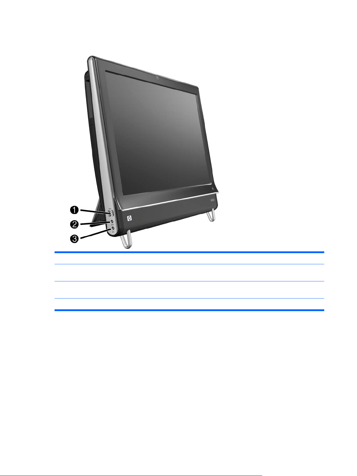
Lower left-side components
Item Item Component
1 USB 2.0 Connect USB devices (USB 2.0) such as printers, external hard disk drives, digital
2 Audio line in Connect MP3 players or other audio players. This connector is not for
3 Headphones Connect headphones to the port to listen to music without disturbing anyone.
cameras, and MP3 players.
headphones or a microphone.
4 Chapter 2 Components
Page 11
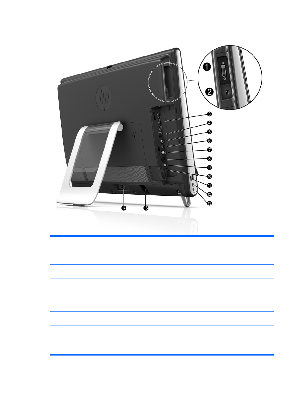
Rear components
Item Item Component
1 DVI Video Out Provides digital video output for use with a second monitor or projector.
2 IEEE 1394 port Provides connectivity to data storage devices and DV (digital video) cameras.
3 USB 2.0 ports (3) Connect USB devices (USB 2.0) such as printers, external hard disk drives, digital
cameras, and MP3 players.
4 Ethernet LAN Connect to the Internet through your wired network.
5 Digital Audio port (SPDIF
Out)
6 Audio line out Connect external 2.0 and 2.1 powered speakers.
7 TV In (TV tuner models
only)
8 S-Video In (TV tuner
models only)
9 Stereo Audio In (TV tuner
models only)
Connect to your home theater system or your surround sound digital speakers.
Supports 3.1, 4.1, and 5.1 speakers.
Connect your TV signal source to watch, record, and pause live TV. This is an Ftype coaxial TV input signal connector.
Capture analog video from a video camera, or connect to a set-top box for TV
input.
Connect audio for A/V input from a set-top box, digital video camera, or other
video device.
Rear components 5
Page 12
10 IR emitter (blaster)
(select models only)
11 USB 2.0 ports (2) Connect USB devices (USB 2.0) such as printers, external hard disk drives, digital
12 Audio Line In Connect MP3 players or other audio players. This connector is not for
13 Headphone jack Connect headphones to the port to listen to music without disturbing anyone.
14 Power connector Plug the power adapter into the computer.
Adhere to your TV set-top box IR receiver area to receive the remote control
signal while watching and recording TV programs. This is not required if you do
not use a set-top box. A remote control is included with select models only.
cameras, and MP3 players.
headphones or a microphone.
15 Wireless keyboard and
mouse receiver
Preinstalled receiver for using a wireless keyboard and mouse.
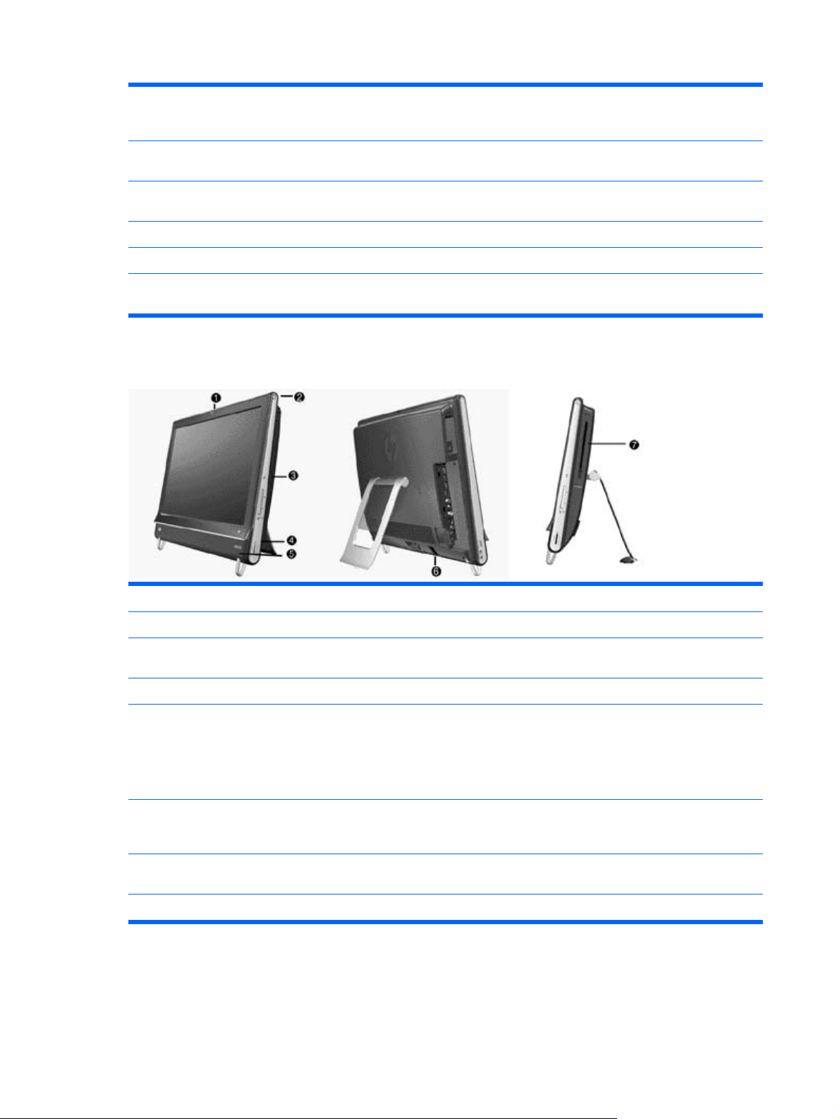
Activity LED indicator lights
Item Item Component
1 Webcam Indicates webcam activity.
2 Power Indicates the power state; blue indicates power on, and amber indicates Sleep
3 Hard disk drive Indicates hard disk drive activity.
mode.
4 Memory card reader Indicates memory card reader activity. When the LED is flashing, do not remove
5 Remote control IR
receiver (select models
only)
6 Wireless keyboard and
mouse receiver
7 Optical Disc Drive Indicates Optical Disc Drive is in use.
6 Chapter 2 Components
your memory card.
When the LED is off, no card is inserted. A solid LED indicates that a card is
inserted with no read or write capacity. A flashing LED indicates that there is
memory card activity, and that a card has read/write capacity.
Indicates that your computer is working with your remote control to navigate
windows, record TV shows, and perform other activities in Windows Media Center.
Indicates wireless signals received from the wireless keyboard and mouse. The
LED is visible from the back of the computer.
Page 13
Computer stand
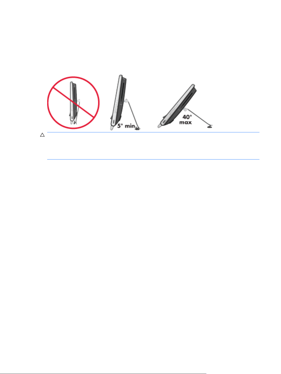
The HP TouchSmart 9100 Business PC is shipped with the computer stand collapsed against the
back of the computer. To assure that the computer is in a stable position on your desktop, pull the
computer stand open until it snaps into place. Then, if you want to change the angle of the HP
TouchSmart 9100, hold each side of the computer, and tilt it (the monitor moves forward; the stand
stays in place) to an angle of between 5 degrees and 40 degrees from the vertical.
CAUTION: The computer stand stays in place as you increase the angle; the computer moves
forward. Take care that the computer screen does not move off the table.
CAUTION: Make sure the angle of the computer is at least 5 degrees from the vertical; otherwise
the computer will be unstable and could fall over.
Computer stand 7
Page 14

3Spare Parts
See the following available spare parts for the HP TouchSmart PC.
Processors and system board
Description Spare Part Number
Intel Core 2 Duo P7570 (2.26-GHz, 3-MB L2 cache) processor 593893-001
Intel Core 2 Duo T6570 (2.10-GHz, 2-MB L2 cache) processor 593892-001
System board 602998-001
Drives
Description Spare Part Number
Hard drives
500 GB, 7200 rpm, SATA 595170-001
320 GB, 7200 rpm, SATA 505914-001
250 GB, 7200 rpm, SATA 595171-001
Solid State Drive (SSD), 64-GB 581057-001
Hard drive adapter, 2.5-inch 586721-001
Optical drives
Blu-ray Disc ROM with SuperMulti DVD±R/RW DL Drive 583093-001
DVD±RW SuperMulti Drive with LightScribe 583092-001
Memory
Description Spare Part Number
SODIMM, 4 GB, PC10600, DDR3-1333 593896-001
SODIMM, 2 GB, PC10600, DDR3-1333 593895-001
8 Chapter 3 Spare Parts
Page 15

Misc Boards
Description Spare Part Number
TV tuner, PCIe x1 card, includes hardware kit 582726-001
GeForce GT230 1-GB PCIe graphics card 593888-001
802.11b/g/n WLAN PCIe adapter 593897-001
Antenna (for use with 802.11b/g/n WLAN PCIe adapter) 593890-001
Power Adapters
Description Spare Part Number
Power adapter, 150W 505911-001
Power adapter, 120W 593891-001
Power cord 142766-005
Keyboards and Mice
Description Spare Part Number
Keyboard (blue, USB)
For use in Brazil 596411-201
For use in French Canada 596411-121
For use in Latin America 596411-161
For use in the United States 596411-371
Keyboard (wireless, 2.4 GHz)
For use in Brazil 596413-201
For use in France 596413-051
For use in Latin America 596413-161
For use in the United States 596413-001
Mice
Mouse, optical, USB 596410-001
Mouse, wireless, 2.4 GHz 596412-001
Misc Boards 9
Page 16

Misc Parts
Description Spare Part Number
Wall mount assembly, VESA 593887-001
Bluetooth module 593889-001
10 Chapter 3 Spare Parts
Page 17
4 Removal and Replacement Procedures
The following sections provide information about disassembling various components of the HP
TouchSmart PC.
Preparing to disassemble the HP TouchSmart PC
To avoid injury and equipment damage, always complete the following steps in order, when opening
the HP TouchSmart PC.
1. Remove all media (CD, DVD, etc.) from the computer.
2. Disconnect any external devices that are connected to the computer.
3. Shut down the computer.
4. After the system has completely shut down, disconnect the power adapter from the back of the
HP TouchSmart PC.
5. Remove the connector cover by inserting your finger under the gap on the bottom-left side of the
cover and then pulling gently.
6. Disconnect all other attached cables from the back of the HP TouchSmart PC.
Preparing to disassemble the HP TouchSmart PC 11
Page 18
7. Place the computer face down on a soft flat surface. HP recommends that you set down a
blanket, towel, or other soft cloth to protect the touch screen surface from scratches or other
damage.
8. Using the notch on the wireless keyboard and mouse receiver, pull the receiver out of and away
from the back of the computer.
WARNING! Beware of sharp edges inside the chassis.
To upgrade your hard disk drive, see Removing the hard drive on page 19.
Hard drive/memory cover
1. Prepare the computer for disassembly (see Preparing to disassemble the HP TouchSmart PC
on page 11).
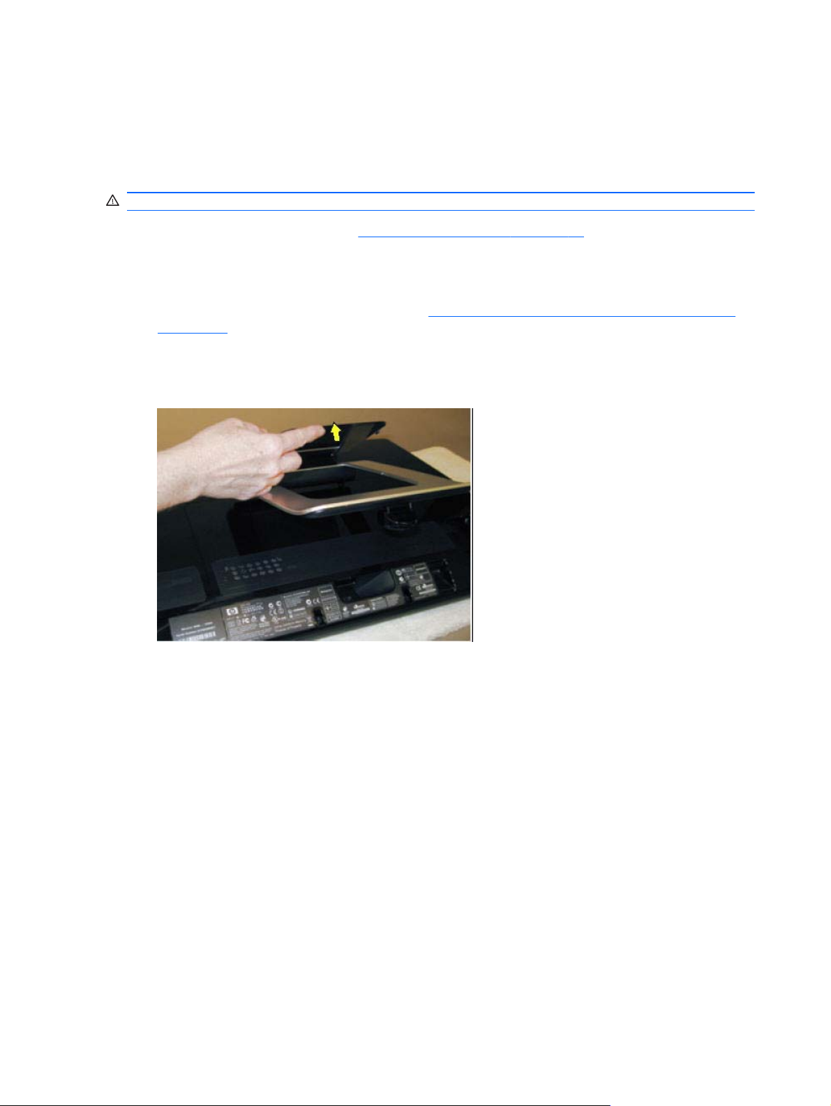
2. Place the computer face down on a soft, flat surface.
3. Lift the stand and pull up on the stand flip cover.
12 Chapter 4 Removal and Replacement Procedures
Page 19
4. Remove the screw that secures the hard drive/memory cover to the computer, and then pull the
bottom edge of the cover away from the computer.
To install the hard drive/memory cover, reverse the removal procedures.
I/O cover
Remove the connector cover on the back of the computer by inserting your finger under the gap
▲
on the bottom-left side of the cover (A), and then pulling straight out gently (B).
To install the I/O cover, reverse the removal procedures.
AB
I/O cover 13
Page 20

Feet
1. Prepare the computer for disassembly (see Preparing to disassemble the HP TouchSmart PC
on page 11).
2. Place the computer face down on a soft, flat surface.
3. Remove the screw that secures the foot to the computer (1).
4. Slide the foot off the computer (2).
To install the feet, reverse the removal procedures.
14 Chapter 4 Removal and Replacement Procedures
Page 21

Stand
1. Prepare the computer for disassembly (see Preparing to disassemble the HP TouchSmart PC
on page 11).
2. Place the computer face down on a soft, flat surface.
3. Remove the hard drive/memory cover (see
4. Remove the four screws that secure the stand to the computer.
Hard drive/memory cover on page 12).
Stand 15
Page 22

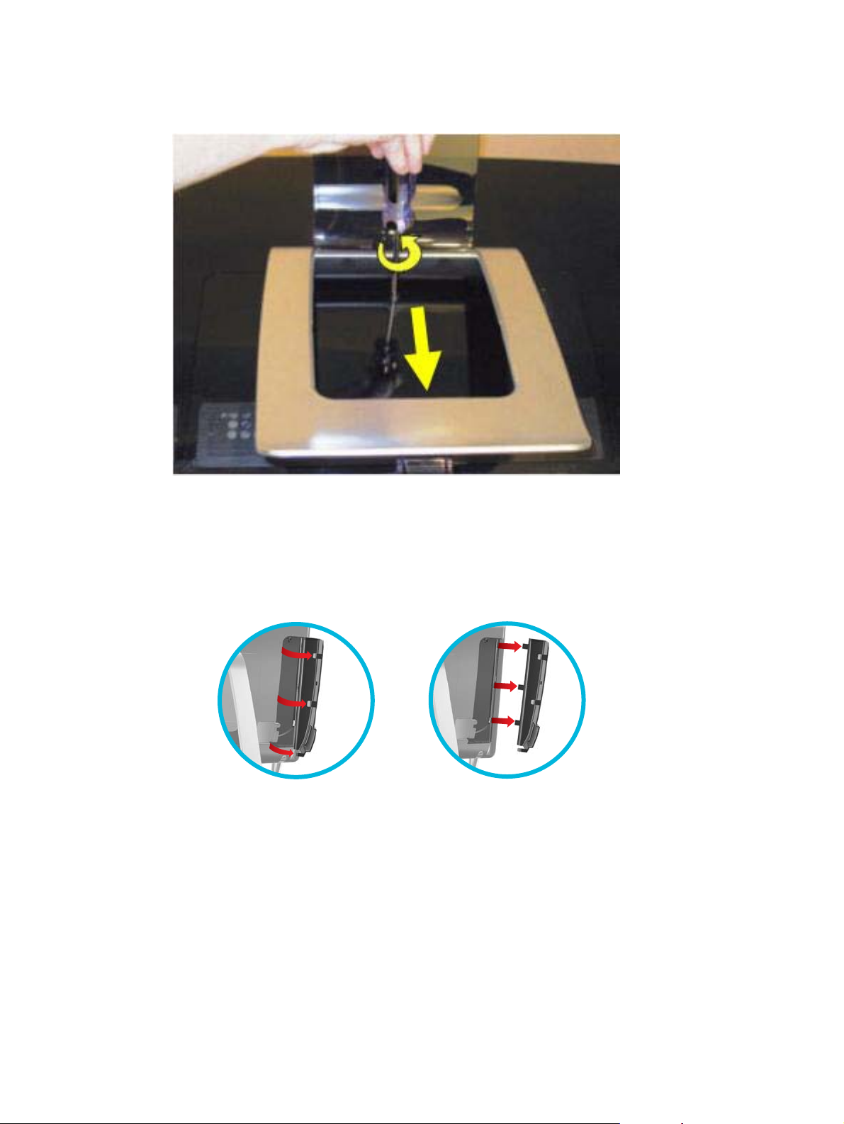
5. Lift the stand straight up and off the computer.
To install the stand, reverse the removal procedures.
When installing the stand, make sure the two tabs fit into the slots in the computer so the stand sits
flush on the back of the computer.
Adding Memory
The HP TouchSmart PC comes with random access memory (RAM), which temporarily stores data
and instructions on your computer. The HP TouchSmart PC ships with one or two memory modules
that you can replace.
Before you begin
Observe the following requirements before removing and replacing the memory module.
The motherboard contains sockets for SODIMMs (small outline dual in-line memory modules).
To determine which type and speed of memory module your HP TouchSmart PC uses, and for
specific memory module information and specifications, go to
CAUTION: Using the wrong type of memory module could damage the computer.
Removing a memory module
1. Prepare the computer for disassembly (see Preparing to disassemble the HP TouchSmart PC
on page 11).
http://www.hp.com/support
2. Place the computer face down on a soft, flat surface.
3. Remove the hard drive/memory cover (see
16 Chapter 4 Removal and Replacement Procedures
Hard drive/memory cover on page 12).
Page 23

4. Lift the cover off the memory module slot.
5. Push the two latches of the retaining clips away from the memory module (1). The memory
module pops up at an angle.
Adding Memory 17
Page 24

6. Lift the memory module from the memory socket by pulling the module away from the slot at an
angle (2).
NOTE: Memory modules are designed with a notch (3) to prevent incorrect insertion into the
memory module slot.
7. Store the memory module in antistatic packaging.
To reinstall memory, reverse the removal procedure.
18 Chapter 4 Removal and Replacement Procedures
Page 25

Removing the hard drive
1. Prepare the computer for disassembly (see Preparing to disassemble the HP TouchSmart PC
on page 11).
2. Place the computer face down on a soft, flat surface.
3. Remove the hard drive/memory cover (see
4. Remove the stand (see
5. Loosen the captured screw (1) that secures the hard drive to the computer.
6. Pull up on the handle (2) of the hard drive assembly, and the pull the assembly partially out of
the computer (3).
Stand on page 15).
Hard drive/memory cover on page 12).
7. Remove the power/data cable from the rear of the hard drive.
8. Remove the hard drive from the computer.
To remove the hard drive from the hard drive cage:
1. Remove the four screws, two on each side, that secure the hard drive into the hard drive cage.
2. Lift the cage off the hard drive.
Removing the hard drive 19
Page 26

Back cover
1. Prepare the computer for disassembly (see Preparing to disassemble the HP TouchSmart PC
on page 11).
2. Place the computer face down on a soft, flat surface.
3. Remove the hard drive/memory cover (see
4. Remove the stand (see
5. Remove the I/O cover (see
6. Remove the feet (see
7. Squeeze the larger of the two pegs (1) holding the I/O cable clip in place and pull the clip off the
pegs (2).
Stand on page 15).
I/O cover on page 13).
Feet on page 14).
Hard drive/memory cover on page 12).
20 Chapter 4 Removal and Replacement Procedures
Page 27

8. Remove the side trims from each side by prying them at the bottom (1) and lifting up and off the
computer (2).
9. Remove the optical drive cover.
Back cover 21
Page 28

10. If the computer includes a game console cover, press the side tab and remove the game
console cover.
11. Remove the 13 screws that secure the back cover to the computer, as follows:
three under each side panel
●
three in the I/O connector area
●
two at the bottom of the back cover
●
two near the optical drive
●
12. Lift the back cover off the computer.
To install the back cover, reverse the removal procedures.
When installing the back cover, note that the back cover has several tabs at the top of the cover that
fit into slots in the top inside of the computer.
Graphics card
1. Prepare the computer for disassembly (see Preparing to disassemble the HP TouchSmart PC
on page 11).
2. Place the computer face down on a soft, flat surface.
3. Remove the hard drive/memory cover (see
4. Remove the stand (see
5. Remove the I/O cover (see
6. Remove the feet (see
7. Remove the back cover (see
Stand on page 15).
I/O cover on page 13).
Feet on page 14).
Back cover on page 20).
Hard drive/memory cover on page 12).
22 Chapter 4 Removal and Replacement Procedures
Page 29

8. Remove the amp board shield by removing the two screws, rotating the top of the shield upward,
and lifting the shield off the computer.
9. Remove the system board shield by removing the nine screws that secure it to the computer,
and then lifting it off the computer.
Graphics card 23
Page 30

10. Disconnect the fan connector from the system board (1), remove the four screws (2) that secure
the fan to the computer, and then loosen the four captive screws (3) that secure the heat sink to
the graphics card in the order indicated on the heat sink.
11. Lift the thermal kit off the system board. The graphics card is located under the metal heat sink.
12. Remove the two screws that secure the graphics card to the system board.
13. Lift the card to a 45-degree angle, and then remove it from the slot at an angle.
To install the graphics card, reverse the removal procedures.
Before reinstalling the system board shield, make sure the small EMI shield near the hard drive is
correctly installed.
When reinstalling a graphics card, be sure to remove all old thermal material and apply new thermal
material.
When installing a new graphics card, be sure to apply thermal material.
WLAN module
1. Prepare the computer for disassembly (see Preparing to disassemble the HP TouchSmart PC
on page 11).
2. Place the computer face down on a soft, flat surface.
3. Remove the hard drive/memory cover (see
4. Remove the stand (see
5. Remove the I/O cover (see
Hard drive/memory cover on page 12).
Stand on page 15).
I/O cover on page 13).
6. Remove the feet (see
7. Remove the back cover (see
24 Chapter 4 Removal and Replacement Procedures
Feet on page 14).
Back cover on page 20).
Page 31

8. Remove the amp board shield by removing the two screws, rotating the top of the shield upward,
and lifting the shield off the computer.
9. Remove the system board shield by removing the nine screws that secure it to the computer,
and then lifting it off the computer.
10. Disconnect the two antenna cables from the module (1).
WLAN module 25
Page 32

11. Remove the two screws that secure WLAN module to the system board (2).
12. Lift the module up to a 45 degree angle, and then remove it from the slot at an angle.
To install the WLAN module, reverse the removal procedures.
WLAN modules include a notch that prevents incorrect installation.
TV tuner module
1. Prepare the computer for disassembly (see Preparing to disassemble the HP TouchSmart PC
on page 11).
2. Place the computer face down on a soft, flat surface.
3. Remove the hard drive/memory cover (see
4. Remove the stand (see
5. Remove the I/O cover (see
6. Remove the feet (see
7. Remove the back cover (see
Hard drive/memory cover on page 12).
Stand on page 15).
I/O cover on page 13).
Feet on page 14).
Back cover on page 20).
26 Chapter 4 Removal and Replacement Procedures
Page 33

8. Remove the amp board shield by removing the two screws, rotating the top of the shield upward,
and lifting the shield off the computer.
9. Remove the system board shield by removing the nine screws that secure it to the computer,
and then lifting it off the computer.
TV tuner module 27
Page 34

10. Locate the TV tuner module on the system board.
11. Detach the side USB I/O module connectors from the system board, and then move them aside
to gain access to the TV tuner module.
12. Disconnect the antenna cable from the top of the module.
13. Disconnect the AV input connector from the side of the module.
14. Remove the two screws that secure the TV tuner module to the system board.
15. Lift the module up to a 45 degree angle, and then remove it from the slot at an angle.
To install the TV tuner module, reverse the removal procedures.
TV tuner modules include a notch that prevents incorrect installation.
28 Chapter 4 Removal and Replacement Procedures
Page 35

System board
1. Prepare the computer for disassembly (see Preparing to disassemble the HP TouchSmart PC
on page 11).
2. Place the computer face down on a soft, flat surface.
3. Remove the hard drive/memory cover (see
4. Remove the stand (see
5. Remove the I/O cover (see
6. Remove the feet (see
7. Remove the hard drive (see
8. Remove the back cover (see
9. Remove the frame support by removing the three screws that secure the frame support to the
computer, and then lifting the support out of the computer.
NOTE: The system board (right) screw is longer than the other screws.
Stand on page 15).
I/O cover on page 13).
Feet on page 14).
Removing the hard drive on page 19).
Back cover on page 20).
Hard drive/memory cover on page 12).
System board 29
Page 36

10. Remove the USB wireless mouse and keyboard receiver, as well as its housing, by pulling both
devices straight out of and off the computer.
11. Remove the graphics card (see Graphics card on page 22).
12. Remove the processor thermal kit as follows:
a. Disconnect the fan cable from the system board (1).
b. Remove the four screws that secure the fan to the system board (2).
c. Loosen the four captive screws in the order indicated on the heat sink (3).
d. Lift the thermal kit from the system board.
13. Remove the WLAN module (see
14. Remove the TV tuner module (see
WLAN module on page 24).
TV tuner module on page 26).
15. Detach all remaining connectors from the system board.
30 Chapter 4 Removal and Replacement Procedures
Page 37

16. Remove the one remaining screw securing the system board to the base pan.
NOTE: If the computer has a gaming console, one of the screws is a grounding screw for the
gaming console DVI connector.
17. Lift the left side of the system board, and then pull the system board out of the computer to the
left at an angle.
NOTE: If replacing the system board, remove the processor and memory and install into the
new system board.
To install the system board, reverse the removal procedures.
Processor
1. Prepare the computer for disassembly (see Preparing to disassemble the HP TouchSmart PC
on page 11).
2. Place the computer face down on a soft, flat surface.
3. Remove the hard drive/memory cover (see
4. Remove the stand (see
5. Remove the I/O cover (see
6. Remove the feet (see
Hard drive/memory cover on page 12).
Stand on page 15).
I/O cover on page 13).
Feet on page 14).
7. Remove the hard drive (see
8. Remove the back cover (see
Removing the hard drive on page 19).
Back cover on page 20).
Processor 31
Page 38

9. Remove the processor thermal kit as follows:
a. Disconnect the fan cable from the system board (1).
b. Remove the four screws that secure the fan to the system board (2).
c. Loosen the four captive screws in the order indicated on the heat sink (3).
d. Lift the thermal kit from the system board.
10. Rotate the locking lever to its full open position (1).
11. Raise and rotate the microprocessor retainer to its full open position (2)
32 Chapter 4 Removal and Replacement Procedures
Page 39

12. Carefully lift the processor from the socket (3).
CAUTION: Do NOT handle the pins in the processor socket. These pins are very fragile and
handling them could cause irreparable damage. Once pins are damaged it may be necessary to
replace the system board.
CAUTION: The heat sink must be installed within 24 hours of installing the processor to
prevent damage to the processor’s solder connections.
To install a new processor:
1. Place the processor in its socket and close the retainer.
2. Secure the locking lever.
If reusing the existing heat sink, go to step 3.
If using a new heat sink, go to step 6.
3. If reusing the existing heat sink, clean the bottom of the heat sink with the alcohol pad provided
in the spares kit.
4. Apply the thermal material provided in the spares kit to the top of the processor and install the
heat sink atop the processor.
5. If using a new heat sink, remove the protective covering from the bottom of the heat sink and
place it in position atop the processor.
Bluetooth module
1. Prepare the computer for disassembly (see Preparing to disassemble the HP TouchSmart PC
on page 11).
2. Place the computer face down on a soft, flat surface.
3. Remove the hard drive/memory cover (see
4. Remove the stand (see
Stand on page 15).
Hard drive/memory cover on page 12).
Bluetooth module 33
Page 40

5. Remove the I/O cover (see I/O cover on page 13).
6. Remove the feet (see
7. Remove the back cover (see
8. Partially remove the left side cap by lifting it straight up and off the computer and resting it next
to the computer with the cables attached.
9. Locate the Bluetooth holder and module assembly.
Feet on page 14).
Back cover on page 20).
10. Push in on the side of the Bluetooth holder, and pull the holder off the computer.
34 Chapter 4 Removal and Replacement Procedures
Page 41

11. Unplug the Bluetooth cable from the Bluetooth module, and then remove the holder assembly
from the computer.
12. Remove the Bluetooth module from the holder by pulling on the small arm at the mouth of the
holder, and then sliding the module out of the holder.
To install the Bluetooth module, reverse the removal procedures.
Optical drive
CD and DVD media can be removed from the optical drive manually, even if the system is not
running.
1. Prepare the computer for disassembly (see
on page 11).
2. Place the computer face down on a soft, flat surface.
3. Remove the hard drive/memory cover (see
4. Remove the stand (see
5. Remove the I/O cover (see
6. Remove the feet (see
7. Remove the back cover (see
8. Disengage the optical drive eject button connector from the cable guide at the side of the optical
drive cage.
Stand on page 15).
I/O cover on page 13).
Feet on page 14).
Back cover on page 20).
Preparing to disassemble the HP TouchSmart PC
Hard drive/memory cover on page 12).
9. Loosen the captured screw that secures the optical drive cage to the computer (1).
Optical drive 35
Page 42

10. Slide the cage out to the side and pull it partially out of the unit (2).
11. Remove the power/data connector cable from the back of the optical drive, and then remove the
drive cage assembly from the computer.
To remove the optical drive from the cage:
1. Remove the four screws, two on each side of the cage.
2. Slide out the optical drive.
Synchronizing the wireless keyboard or mouse
The wireless keyboard and mouse are pre-synchronized for your convenience, to work with your HP
TouchSmart PC. They should work immediately after pulling the battery tabs, which activate the preinstalled batteries, and turning the mouse switch on (2).
You may need to manually synchronize the wireless keyboard or mouse if they are not functioning.
To synchronize them:
Make sure the keyboard and mouse are next to the HP TouchSmart PC, within 30 cm (1 foot)
●
and away from interference from other devices.
Keyboard: Press the connect button on the bottom of the keyboard (1) for five seconds. The
●
blue activity LED from the wireless receiver illuminates when the synchronization command has
been received and turns off when synchronization is complete.
Mouse: Press the connect button on the bottom of the mouse (3) for five seconds. The blue
●
activity LED from the wireless receiver illuminates when the synchronization command has been
received and turns off when synchronization is complete.
36 Chapter 4 Removal and Replacement Procedures
Page 43

If this does not work, remove and then reinsert the wireless keyboard and mouse receiver from the
back of the computer and then synchronize the keyboard and mouse again.
Synchronizing the wireless keyboard or mouse 37
Page 44

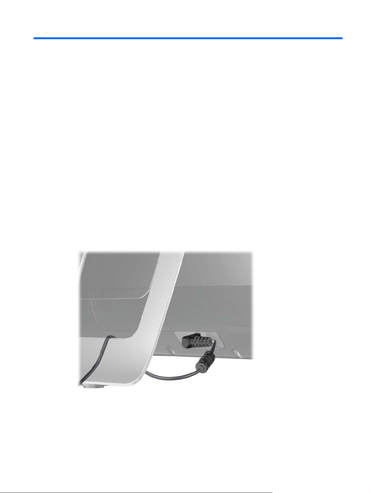
Installing a Security Lock
A security lock (sold separately) enables you to secure your computer from theft and unwanted
changes. A security lock is a key lock device that has a wire cable attached. You attach one end of
the cable to your desk (or other stationary object) and the other to this security slot on the computer.
Secure the security lock with the key.
38 Chapter 4 Removal and Replacement Procedures
Page 45

5 Computer Setup (F10) Utility
Computer Setup (F10) Utilities
Access the BIOS Setup Utility by pressing the F10 button during startup. Use Computer Setup (F10)
Utility to do the following:
Change factory default settings.
●
Set the system date and time.
●
Set, view, change, or verify the system configuration, including settings for processor, graphics,
●
memory, audio, storage, communications, and input devices.
View processor and memory settings
●
Modify the boot order of bootable devices such as hard drives, diskette drives, optical drives, or
●
USB media.
Run hard drive self-tests.
●
Establish a supervisor password that controls access to Computer Setup (F10) Utility and the
●
settings described in this section.
Using Computer Setup (F10) Utilities
Computer Setup can be accessed only by turning the computer on or restarting the system.
To access the Computer Setup Utilities menu, complete the following steps:
1. Turn on or restart the computer.
2. As soon as the computer is turned on, press F10 before the system boots to the operating
system to enter Computer Setup. Press Enter to bypass the title screen, if necessary.
NOTE: If you do not press F10 at the appropriate time, you must restart the computer and
again press F10 before the unit boots to the operating system to access the utility.
3. The Computer Setup Utility screen is divided into menu headings and actions.
Five menu headings appear on the Computer Setup Utility screen:
Main
●
Advanced
●
Boot
●
Computer Setup (F10) Utilities 39
Page 46

Power
●
Exit
●
Use the arrow keys to select the appropriate heading, then press Enter. Use the arrow (up and
down) keys to select the option you want, then press Enter. To return to the previous screen,
press Esc.
4. To apply and save changes, press the F10 key.
If you have made changes that you do not want applied, press the F5 key to return to the default
values.
CAUTION: Do NOT turn the computer power OFF while the ROM is saving the Computer Setup
(F10) changes because the CMOS could become corrupted. It is safe to turn off the computer only
after exiting the F10 Setup screen.
Table 5-1 Computer Setup (F10) Utility Main Menu
Heading Table
Main Computer Setup—Main on page 40
Advanced
Boot
Power
Exit
Computer Setup—Main
NOTE: Support for specific Computer Setup options may vary depending on the hardware
configuration.
Table 5-2 Computer Setup—Main
Option Description
System Time Allows you to set system time.
System Date Allows you to set system date.
Language Allows you to select language.
Floppy Diskette A: Allows you to set drive A to:
Disabled
●
1.44 MB 3.5”
●
Computer Setup—Advanced on page 41
Computer Setup—Boot on page 43
Computer Setup—Power on page 42
Computer Setup—Exit on page 44
● Not Installed
40 Chapter 5 Computer Setup (F10) Utility
Page 47

Table 5-2 Computer Setup—Main (continued)
1st Drive
2nd Drive
System Information (view only)
For each, allows you to:
Port Configuration (disable/enable)
●
(view only)
●
◦ Capacity (Size - HDD only)
◦
Smart Support - run HDD self-test for selected channel:
●
◦
◦
◦ SMART Extended Self-Test
● Installed Memory
Memory Bank 1
●
Memory Bank 2
●
● BIOS Revision
Core Version
●
Product Number
●
Transfer Mode
SMART Status Check
SMART Short Self-Test
● Model Number
Serial Number (press Enter to change)
●
Asset Tag (press Enter to change)
●
Computer Setup—Advanced
NOTE: Support for specific Computer Setup options may vary depending on the hardware
configuration.
WARNING! Setting items on this menu to incorrect values may cause your system to malfunction.
Table 5-3 Computer Setup—Advanced
Option Description
CPU Type (view only)
CPU Speed (view only)
Cache RAM (view only)
SATA1 Controller Allows you to disable/enable the SATA Controller.
SATA Controller Mode If SATA1 Controller is enabled, allows you to set the mode to:
● IDE
AHCI
●
USB Ports Allows you to enable/disable individual USB ports (USB Port 1 through USB Port 7).
Computer Setup (F10) Utilities 41
Page 48

Table 5-3 Computer Setup—Advanced (continued)
Onboard LAN Allows you to disable/enable onboard LAN controller.
Onboard LAN Boot
ROM
Onboard 1394 Allows you to disable/enable onboard 1394 port.
Onboard WLAN Allows you to set the on-board WLAN to:
Onboard TV-Tuner Allows you to set the on-board TV tuner to:
Security Option Checks password while invoking Setup or while invoking Setup as well as on each System boot.
Supervisor Password Allows you to view the supervisor password.
User Password Allows you to view the user password.
Onboard Audio Allows you to set the on-board audio to:
Allows you to disable/enable the boot ROM of the onboard LAN chip.
● Enabled
Disabled
●
Enabled
●
Disabled
●
Set to:
● Setup
System
●
Enabled
●
●
Change Supervisor
Password
Allows you to change the supervisor password.
Computer Setup—Power
NOTE: Support for specific Computer Setup options may vary depending on the hardware
configuration.
Table 5-4 Computer Setup—Power
Option Description
After AC Power
Failure
XD (Execute Disable) Disables/enables the processor's XD feature.
Virtualization
Technology
Allows you to select system restart behavior after power loss:
●
●
● Auto
Allows you to disable/enable Virtualization Technology.
Disabled
Stay Off
Power On
42 Chapter 5 Computer Setup (F10) Utility
Page 49

Table 5-4 Computer Setup—Power (continued)
S5 Maximum Power
Savings
WOL in S5 Disables/enables limited Wake on LAN from S5. Note that the computer can only wake from S5
Disables/enables S5 Maximum Power Savings. Enabling this feature reduces the power of this
system as much as possible in the S5 state. This feature must be disabled if you want to enable
Wake on LAN from S5.
during a normal shutdown event. The S5 Maximum Power Savings feature must be disabled in
order to enable limited Wake on LAN from S5.
Computer Setup—Boot
NOTE: Support for specific Computer Setup options may vary depending on the hardware
configuration.
Table 5-5 Computer Setup—Boot
Option Description
Boot-time Diagnostic
Screen
Esc: Boot Menu Disables/enables POST Esc: Boot Menu message display,
F9: Diagnostics Disables/enables POST F9: Diagnostics message display,
F10: Setup Disables/enables POST F10: Setup message display,
F11: Recovery Disables/enables POST F11: Recovery message display,
Disables/enables POST diagnostic messages display.
F12: Boot From LAN Disables/enables POST F12: Boot From LAN message display,
(Boot Device Priority)
1st Boot Device
2nd Boot Device
3rd Boot Device
4th Boot Device
Floppy Group Boot
Priority
CD-ROM Group Boot
Priority
HDD Group Boot
Priority
Network Group Boot
Priority
Allows you to specify which device groups will boot first, second, third, and fourth or to disable any
of the four:
CD-ROM Group
●
HDD Group
●
Floppy Group
●
Network Boot Group
●
NOTE: MS-DOS drive lettering assignments may not apply after a non-MS-DOS operating
system has started.
Specifies boot device priority within removable devices.
Specifies boot device priority within CD/DVD drives.
Specifies boot device priority within hard drives.
Specifies boot device priority within bootable network devices.
Computer Setup (F10) Utilities 43
Page 50

Computer Setup—Exit
NOTE: Support for specific Computer Setup options may vary depending on the hardware
configuration.
Table 5-6 Computer Setup—Exit
Option Description
Exit Saving Changes Press Enter to exit saving changes.
Exit Discarding
Changes
Load Setup Defaults Press Enter to load setup defaults.
Discard Changes Press Enter to discard changes.
Save Changes Press Enter to save changes.
BIOS updates
HP periodically releases system BIOS updates, which are available from the HP website. These
updates often contain fixes for known issues in the BIOS.
To find out whether a PC needs a BIOS update, compare the current BIOS version number against
the latest version available for download. To determine the current BIOS version, you should perform
the following steps:
1. Click Start, and then select Shut Down.
2. Select Restart, and then click OK.
3. When the first screen displays, press F10 to enter Setup. The BIOS revision number is listed on
the Main menu.
4. Write down the current BIOS version that is listed.
Press Enter to exit discarding changes.
5. To exit Setup, press Esc, select Yes, and then press Enter.
44 Chapter 5 Computer Setup (F10) Utility
Page 51

6 Software Troubleshooting
Your computer uses the operating system and installed software programs during normal operation. If
your computer works improperly or stops because of the software, you may be able to repair it.
Some software repairs are as simple as restarting your computer, and others require performing a
system recovery from files on your hard disk drive.
Software Repair Overview
The most efficient way to repair software problems is simply to restart the computer or turn the
computer off completely and then power it back up again. If this does not work, then explore the
following methods for fixing your computer if you are experiencing software problems:
Updating Drivers
●
Microsoft System Restore
●
Software Program and Hardware Driver Reinstallation
●
System Recovery
●
Updating Drivers
A driver is a software program that enables your computer to communicate with an attached device,
such as a printer, hard disk drive, mouse, or keyboard.
Complete the following procedure to update a driver, or to revert to an earlier version of the driver if
the new one does not solve your problem:
1. Click the Start button.
2. Type Device Manager into the Start Search box, and then click Device Manager to open the
Device Manager window.
3. Click the plus sign (+) to expand the type of device for which you want to update or rollback, (for
example, DVD/CD-ROM drives).
4. Double-click the specific item (for example, HP DVD Writer 640b).
5. Click the Driver tab.
6. To update a driver, click Update Driver, and follow the on-screen instructions.
– or –
Software Repair Overview 45
Page 52

To revert to an earlier version of a driver, click Rollback Driver, and follow the on-screen
instructions.
Microsoft System Restore
Microsoft Windows 7 includes a feature that enables you to restore your computer configuration to a
configuration that was in use before the current software problem existed. The feature does this by
creating a restore point where it records the computer settings at that time and date.
When a new program is installed, the operating system automatically creates a restore point before it
adds the new software. You can also set restore points manually.
If you experience a problem that you think may be due to software on your computer, use System
Restore to return the computer to a previous restore point.
NOTE: Always use this System Restore procedure before you use the system recovery program.
To start a System Restore:
1. Close all open programs.
2. Click the Start button, right-click Computer, and then click Properties.
3. Choose System protection, System Restore, and then click Next.
4. Follow the on-screen instructions.
To manually add restore points:
1. Close all open programs.
2. Click the Start button, right-click Computer, and then click Properties.
3. Click System protection.
4. Under Protection Settings, select the disk for which you want to create a restore point.
5. Click Create.
6. Follow the on-screen instructions.
For more information about software restore points:
1. Click the Start button, and then click Help and Support.
2. Type system restore into the Search box, and then press Enter.
Software Program and Hardware Driver Reinstallation
If an individual factory-installed software program or hardware driver is damaged, you can reinstall it
by using the Recovery Manager program (select models only).
NOTE: Do not use the Recovery Manager program to reinstall software programs that came on
CDs or DVDs included in the computer box. Reinstall these programs directly from the CDs or DVDs.
Before you uninstall a program, be sure you have a way to reinstall it. Check that it is still available
from where you initially installed it (for example, discs or the Internet). Or check that the program is in
the list of programs you can reinstall from the Recovery Manager.
46 Chapter 6 Software Troubleshooting
Page 53

To check the list of installable programs in the Recovery Manager:
1. Click the Start button, All Programs, Recovery Manager, and then click Recovery Manager. If
prompted, click Yes to allow the program to continue.
2. Under I need help immediately, click Software Program Reinstallation.
3. Click Next at the Welcome screen.
A list of programs opens. Check whether your program is there.
To uninstall a program:
1. Close all software programs and folders.
2. Uninstall the damaged program:
a. Click the Start button, and then click Control Panel.
b. Under Programs, click Uninstall a program.
c. Select the program you want to remove, and then click Uninstall.
d. Click Yes if you want to continue with the uninstall process.
To reinstall a program using the Recovery Manager:
1. Click the Start button, click All Programs, click Recovery Manager, and then click Recovery
Manager.
2. Click Software Program Reinstallation.
3. Click Next at the Welcome screen.
4. Choose the program you want to install, click Next, and follow the on-screen instructions.
5. When you have finished reinstalling, restart the computer.
NOTE: Do not skip this last step. You must restart the computer when you are finished recovering
software programs or hardware drivers.
Software Program and Hardware Driver Reinstallation 47
Page 54

Creating data backup discs
Use CD or DVD recording (or burning) software that is installed on your computer to create backup
discs of important information, including personal files, e-mail messages, and Web site bookmarks.
You can also move data to an external hard disk drive.
When writing data to a backup disc, use software that includes write verification functionality. This
feature compares the data on your hard disk drive with the data copied to the disc to ensure it is an
exact copy. Depending on your disc recording software, you may need to manually enable this
feature (refer to the software documentation).
If you encounter recording issues, try alternate media (different types or brands). Also, use the
Windows Explorer tool to view your files and verify content was copied over. To open Windows
Explorer, right-click the Start button, and then click Explore.
Clearing CMOS
When the BIOS has been incorrectly configured, it is sometimes necessary to clear all CMOS
settings.
To clear the CMOS, users need to perform the following steps:
CAUTION: Before attempting to remove or touch any parts from the motherboard, check that the
power cord is disconnected from the electrical outlet. Failing to do so can cause hardware damage
and even physical injury.
1. Shut down the operating system and turn off the computer and any external devices.
2. Disconnect the power cords of the computer and any external devices from the power outlet.
3. Disconnect any external devices that are connected to the computer.
4. Remove the chassis cover.
5. Locate the CMOS jumper header on the motherboard.
CAUTION: Removing the incorrect jumper can cause the system configuration to be changed
or even cause irreparable hardware damage.
6. Set the jumper to cover the middle and third pins for at least five seconds.
7. Set the jumper back in its original position.
8. Replace the hood cover.
9. Reconnect the external equipment.
10. Plug in the computer and turn on the power. Allow the operating system to start.
Clearing BIOS passwords
If a user has configured a power-on or setup password using the BIOS and then loses the password,
they cannot access the BIOS in order to change or clear the password.
In this event, to clear the power-on or setup passwords—or to disable the power-on or setup
password feature—users need to perform the following steps:
48 Chapter 6 Software Troubleshooting
Page 55

CAUTION: Before attempting to remove or touch any parts from the motherboard, check that the
power cord is disconnected from the electrical outlet. Failing to do so can cause hardware damage
and even physical injury.
1. Shut down the operating system and turn off the computer and any external devices.
2. Disconnect the power cords of the computer and any external devices from the power outlet.
3. Disconnect any external devices that are connected to the computer.
4. Remove the chassis cover.
5. Locate the BIOS password jumper header on the motherboard.
CAUTION: Removing the incorrect jumper can cause the system configuration to be changed
or even cause irreparable hardware damage.
6. Move the jumper to cover the middle and third pins for at least five seconds. This clears the
current passwords.
7. Replace the jumpers in their default positions.
8. Replace the chassis cover.
9. Reconnect the external equipment.
10. Plug in the computer and turn on the power. Allow the operating system to start.
Power-On Self Test (POST)
When the system is turned on, all installed components are tested to verify that they are working
properly. This series of tests is called the Power-On Self-Test.
The POST runs basic tests on the following system components:
Installed hardware
●
Memory
●
● Cache
● PCI data path
Flash ROM
●
If an error occurs during POST, the HP TouchSmart 9100 Business PC does one or both of the
following:
Displays an error message describing the problem
●
Sounds a beep code
●
Power-On Self Test (POST) 49
Page 56

Troubleshooting
Media Card Reader
Cause Solution
Clicking Stop in the Safely Remove Hardware window with
the USB Mass Storage Device selected results in the
operating system no longer recognizing the Memory Card
Reader.
Optical disk drive (ODD)
Cause Solution
8 cm optical discs are sometimes rejected by the drive or
become stuck in the drive.
Restart the PC to have it recognize the Memory Card Reader
again.
Insert the disc in the center of the slot, instead of inserting
towards the top or bottom of the slot.
The HP TouchSmart 9100 includes the following specific tests:
Screen Health test to support the touch-enabled display
●
a. Verifies the touch signal strength and available touch regions.
b. Screen Coverage test analyzes all touch regions.
c. If below the test threshold, logs a warning in the test log.
d. Cllean the bezel and run the test again.
Webcam test
●
Microphone test
●
Determining Whether Your System Is 64-bit or 32-bit
1. Tap the Start button, and then tap Help and Support.
2. Tap Troubleshooting Tools, and then tap System Information.
3. Tap Touch here to open System Information.
4. After the System Information displays, view Operating System, Name. It will appear as either
(64-bit) or (32-bit).
50 Chapter 6 Software Troubleshooting
Page 57

7 System Recovery
System recovery completely erases and reformats the hard disk drive, deleting all data files you have
created. System recovery reinstalls the operating system, programs, and drivers. However, you must
reinstall any software that was not installed on the computer at the factory. This includes software that
came on CDs included in the computer accessory box, and software programs you installed after
purchase.
You must choose from the following methods for performing a System Recovery:
Recovery Image—Run the system recovery from a recovery image stored on your hard disk drive.
The recovery image is a file that contains a copy of the original factory-shipped software. To perform
a system recovery from the recovery image on your hard disk drive.
NOTE: The recovery image uses a portion of the hard disk drive that cannot be used for data
storage.
Recovery Discs—Run the system recovery from a set of recovery discs that you create from files
stored on your hard disk drive.
Creating Recovery Discs
Complete the procedure described in this section to create a set of recovery discs from the recovery
image stored on your hard disk drive. This image contains the operating system and software
program files that were originally installed on your computer at the factory.
You can create only one set of recovery discs for your computer. Furthermore, the recovery discs you
create can be used only with your computer.
Choosing Recovery Discs
To create recovery discs, your computer must have a DVD writer.
Use DVD+R or DVD-R blank media to create your system recovery discs.
●
You cannot use DVD+RW, DVD-RW, DVD+RW DL, DVD-RW DL, DVD+R DL, DVD-R DL, or
●
CD discs to create recovery discs.
Use high-quality discs to create your set of recovery discs. The verification standard for the recovery
disc creation process is very high. You may see error messages such as Recording failure when
writing disc or Error detected during disc verification.
Your discs may be rejected if they are not defect-free. You will be prompted to insert a new blank disc
to try again. It is normal that some of your discs may be rejected.
Creating Recovery Discs 51
Page 58

The number of discs in the recovery disc set depends on your computer model (typically 1–3 DVD
discs). The Recovery Disc Creator program tells you the specific number of blank discs needed to
make the set.
The process takes some time to verify that the information written on the disc is correct. You can quit
the process at any time. The next time you run the program, it resumes where it left off.
To create recovery discs:
1. Close all open programs.
2. Tap the Start button, All Programs, Recovery Manager, and then tap Recovery Disc
Creation. If prompted, tap Yes to allow the program to continue.
3. Follow the on-screen instructions. Label each disc as you make it (for example, Recovery 1,
Recovery 2).
4. Store the Recovery discs in a safe place.
System Recovery Options
You should attempt system recovery in the following order:
1. Through the hard disk drive, from the Windows 7 Start menu.
2. Through the hard disk drive, by pressing the F11 key on the keyboard during system startup.
3. Through recovery discs that you create.
4. Through recovery discs purchased from HP Support. To purchase recovery discs, go to
http://www.hp.com/support and visit the Software & Driver downloads page for your computer
model.
System recovery from the Windows 7 Start menu
If the computer is working, and Windows 7 is responding, use these steps to perform a system
recovery.
NOTE: System Recovery deletes any data or programs that you created or installed after purchase.
Therefore, ensure you have backed up to a removable disc any data that you want to keep.
1. Turn off the computer.
2. Disconnect all peripheral devices from the computer, except the monitor, keyboard, and mouse.
3. Turn on the computer.
4. Tap the Start button, All Programs, Recovery Manager, and then tap Recovery Manager. If
prompted, tap Yes to allow the program to continue.
5. Under I need help immediately, tap System Recovery.
6. Tap Yes, and then tap Next.
Your computer restarts.
NOTE: If your system does not detect a recovery partition, it will prompt you to insert a
recovery disc.
52 Chapter 7 System Recovery
Page 59

7. Under I need help immediately, tap System Recovery.
8. If you are prompted to back up your files, and you have not done so, select Back up your files
first (recommended) button, and then tap Next. Otherwise, select Recover without backing
up your files button, and then tap Next.
System recovery begins. After system recovery is complete, tap Finish to restart the computer.
9. Complete the registration process, and wait until you see the desktop.
10. Turn off the computer, reconnect all peripheral devices, and turn the computer back on.
System recovery at system startup
If Windows 7 is not responding, but the computer is working, use these steps to perform a system
recovery:
NOTE: System Recovery deletes any data or programs that you created or installed after purchase.
Therefore, ensure you have backed up to a removable disc any data that you want to keep.
1. Turn off the computer. If necessary, press and hold the On button until the computer turns off.
2. Disconnect all peripheral devices from the computer, except the monitor, keyboard, and mouse.
3. Press the On button to turn on the computer.
4. As soon as you see the initial company logo screen appear, repeatedly press the F11 key on
your keyboard until the Windows is Loading Files message appears on the screen.
5. Under I need help immediately, tap System Recovery.
6. If you are prompted to back up your files, and you have not done so, select Back up your files
first (recommended) button, and then tap Next. Otherwise, select Recover without backing
up your files button, and then tap Next. Otherwise, select Recover without backing up your
files button, and then tap Next.
System recovery begins. After system recovery is complete, tap Finish to restart the computer.
7. Complete the registration process, and wait until you see the desktop.
8. Turn off the computer, reconnect all peripheral devices, and turn the computer back on.
Starting system recovery from recovery discs
This section contains the procedure for performing a system recovery from the recovery discs you
created.
NOTE: System Recovery deletes any data or programs that you created or installed after purchase.
Therefore, ensure you have backed up to a removable disc any data that you want to keep.
To perform a system recovery program using recovery discs:
1. If the computer is working, create a backup DVD containing all the data files you want to save.
When you are done, remove the backup disc from the disc tray.
CAUTION: All data on the hard disk drive will be deleted. You will lose data if it is not backed
up.
2. Disconnect all peripheral devices from the computer, except the keyboard and mouse.
System Recovery Options 53
Page 60

3. Insert recovery disc #1 into the DVD drive tray, and close the tray.
4. If the computer works, click the Start button, click the Arrow button next to Shut Down, and
then click Shut Down.
– or –
If the computer is not responding, press and hold the On button for approximately 5 seconds, or
until the computer turns off.
5. Disconnect all peripheral devices from the computer, except the monitor, keyboard, and mouse.
6. Press the On button to turn on the computer.
If you are prompted to choose between running System Recovery from disc or from hard drive,
select Run program from disc, and then click Next.
7. Under I need help immediately, tap Factory Reset.
8. If you are prompted to back up your files, and you have not done so, select Back up your files
first (recommended) button, and then tap Next. Otherwise, select Recover without backing
up your files button, and then click Next.
9. If you are prompted to insert the next recovery disc, do so.
10. When the Recovery Manager is finished, remove all recovery discs from the system.
11. Click Finish to restart the computer.
54 Chapter 7 System Recovery
Page 61

Index
A
activity lights 6
adapter 9
adding memory 16
Audio Line In 6
audio line-in 4
audio line-out 5
B
back cover, removing 20
Bluetooth 2
Bluetooth module, removing 33
C
CD/DVD drive 3
choosing recovery discs 51
components
front 2
left-side 4
rear 5
creating recovery discs 51
D
drivers
reinstalling 46
updating 45
DVI Video Out 5
E
ethernet 5
F
feet, removing 14
front components 2
G
graphics card, removing 22
H
hard drive
removing 12
hard drive light 6
hard drive/memory cover,
removing 12
hardware reinstallation 46
Headphone jack 6
headphones 4
I
I/O cover, removing 13
IEEE 1394 port 5
IR emitter 6
K
keyboard 9
L
LEDs 6
left-side components 4
lights
hard drive 6
memory card reader 6
optical disc 6
power 6
Remote control IR receiver 6
webcam 6
wireless keyboard and mouse
receiver 6
M
memory
adding 16
removing 16
memory card reader 3
memory card reader light 6
microphone 3
Microsoft System Restore 46
mouse 9
O
opening the computer 11
optical drive light 6
P
power adapter 9
power button 3
power connector 6
power cord 9
power light 6
processor
removal and replacement 31
R
rear components 5
recovery
at system startup 53
from the Windows 7 Start
menu 52
starting from recovery
discs 53
recovery discs
choosing 51
creating 51
recovery options 52
Remote control IR receiver light 6
removal and replacement
processor 31
removal and replacement
procedures
11
back cover 20
Bluetooth module 33
feet 14
graphics card 22
hard drive 12
hard drive/memory cover 12
I/O cover 13
memory, adding 16
optical disc 35
Index 55
Page 62

preparing to disassemble the
TouchSmart PC 11
stand 15
system board 29
TV tuner module 26
WLAN module 24
removing
hard drive 12
removing memory 16
repairing software problems 45
restoring the system 46
right-side components 2
S
S-Video In 5
SODIMM 8
software problems 45
software reinstallation 46
SPDIF 5
speakers 3
stand assembly 15
Stereo Audio In 5
system board, removing 29
system recovery options 52
T
TouchSmart button 3
TV In 5
TV tuner module, removing 26
U
updating drivers 45
USB 2.0 4, 5
V
VESA wall mount assembly 10
volume 3
W
wall mount assembly 10
webcam 3
webcam light 6
wireless keyboard and
mouse 3, 6
wireless keyboard and mouse
receiver light 6
wireless LAN 3
WLAN module, removing 24
56 Index
 Loading...