

HP SureStore Optical Jukebox 160ex, SureStore Optical Jukebox 320ex, SureStore Optical Jukebox 400ex, SureStore Optical Jukebox 300mx, SureStore Optical Jukebox 600mx Service Manual
...
HP SureStore Optical Jukebox
160ex/320ex/400ex/300mx/600mx/700mx
Service Manual
Edition 1
Manufacturing Part Number: HP Part No. C1160-90031
Greeley, CO USA
© Copyright August 2000

Notice
This document contains information that is protected by copyright. All
rights are reserved. No part of this document may be photocopied,
reproduced, or translated to another language without the prior written
consent of Hewlett-Packard Company. The information contained in this
document is subject to change without notice.
Hewlett-Packard makes no warranty of any kind with regard to this
printed material, including, but not limited to, the implied warranties of
merchantability and fitness for a particular purpose. Hewlett-Packard
shall not be liable for errors contained herein or for incidental or
consequential damages in connection with the furnishing,
performance, or use of this material.
© Copyright August 2000
Printing History
New editions of this manual incorporate all material updated since the
previous edition. The manual printing date and part number indicate the
current edition. The printing date changes when a new edition is printed.
(Minor corrections and updates incorporated at reprint do not change
this date.)
Part Number C1160-90031 Edition 1 August 2000
ii

Typographical Conventions
The following typographical conventions are used in this manual:
Emphasis: Denotes important information.
Keycap: Keys on the control panel.
Computer Output: Information displayed in the display window and
menu items that you can select.
WARNING Warnings call attention to a procedure or practice that could
result in personal injury if not correctly performed. Do not
proceed until you fully understand and meet the required
conditions.
CAUTION Cautions call attention to an operating procedure or practice that could
damage the product if not correctly performed. Do not proceed until you
understand and meet the required conditions.
NOTE Notes provide information that aid in understanding the operation of the
product.
iii

In This Manual
This user’s guide includes:
Chapter 1 Product Information
Chapter 2 Installation
Chapter 3 Operation and Configuration
Chapter 4 Troubleshooting and Diagnostics
Chapter 5 Removal and Replacement
Chapter 6 Theory of Operation
Appendix A Safety and Regulatory Information
Index
iv

Contents
1. Product Information
Overview ............................................................................................... 1-2
Technical Specifications ....................................................................... 1-3
Environmental Specifications .............................................................. 1-6
Clearance Requirements................................................................ 1-9
Location Requirements .................................................................. 1-10
Responsibilities .............................................................................. 1-11
2. Installation
Overview ............................................................................................... 2-2
Identifying Controls and Features ...................................................... 2-3
Connecting SCSI Cables to the Jukebox ............................................. 2-6
Connecting the Jukebox as the Only Peripheral ................................ 2-8
Connecting the Jukebox With Other SCSI Peripherals ..................... 2-10
Connecting Power ................................................................................ 2-11
Configuring Write Verify...................................................................... 2-12
Default SCSI IDs in the Jukebox When Using Basic
SCSI Addressing and When Using LUN Mode............................... 2-13
Moving or Shipping the Jukebox ......................................................... 2-19
Moving the Jukebox a Short Distance .......................................... 2-19
Shipping the Jukebox..................................................................... 2-20
3. Operation and Configuration
Overview .............................................................................................. 3-2
Operating the Control Panel ................................................................ 3-3
TOC-v

Contents
Using Selection Buttons....................................................................... 3-7
Understanding Display Window Messages......................................... 3-8
Top Level Menus............................................................................ 3-8
Second Level Menus ...................................................................... 3-8
Loading a Disk...................................................................................... 3-10
Ejecting a Disk ..................................................................................... 3-11
Entering the Administration Menu Password.................................... 3-12
Changing the Administration Menu Password .................................. 3-13
Setting the SCSI IDs............................................................................ 3-15
Setting the LUN Mode................................................................... 3-15
Viewing the Current SCSI IDs...................................................... 3-15
Changing the Current SCSI IDs ................................................... 3-17
Setting an Operating Configuration ................................................... 3-20
Retrieving Log History......................................................................... 3-24
4. Troubleshooting and Diagnostics
Overview .............................................................................................. 4-2
Troubleshooting Using the Control Panel........................................... 4-3
Obtaining Troubleshooting Information....................................... 4-3
List of Possible Suspect FRUs....................................................... 4-3
Recovery Procedures for Operation/Installation Errors..................... 4-5
Recovery Procedures for Specific Hardware Errors ........................... 4-14
Micro-Move Error Codes ...................................................................... 4-26
Description of Micro-Moves ................................................................. 4-30
Running an Internal Test .................................................................... 4-43
TOC-vi

Contents
5. Removal and Replacement
Overview ............................................................................................... 5-2
Protecting Yourself and the Product.................................................... 5-3
Electrostatic Discharge (ESD) Precautions .................................. 5-3
Required Tools................................................................................ 5-3
Service Access ....................................................................................... 5-5
Removing the Right, Left, and Rear Access Panels ..................... 5-5
Removing the Left and Right Front Panels.................................. 5-6
Replacing a Power Supply.................................................................... 5-9
Replacing the Mailslot Assembly......................................................... 5-11
Reassembly Notes .......................................................................... 5-12
Replacing the Control Panel Assembly ............................................... 5-13
Reassembly Notes .......................................................................... 5-13
Replacing an Optical Drive — Jukebox Offline .................................. 5-15
Replacing an Optical Drive — Jukebox Online................................... 5-19
Reassembly Notes .......................................................................... 5-24
Replacing the Interposer PCA ............................................................. 5-26
Replacing the Picker............................................................................. 5-27
Removing/Replacing the Translate Frame (Including the Picker) .... 5-33
Reassembly Notes .......................................................................... 5-39
Removing/Replacing the Vertical Encoder Strip................................. 5-42
Replacing the Vertical Motion Motor................................................... 5-44
Replacing the Vertical Motor Gear Box............................................... 5-46
Reassembly Notes .......................................................................... 5-48
TOC-vii

Contents
Replacing the Controller PCA ............................................................. 5-50
Replacing the Interface PCA ............................................................... 5-52
Replacing the SCSI Cable .................................................................... 5-55
Checking the RFI Adjustments ........................................................... 5-56
Upgrading Firmware to the Current Revision Level ......................... 5-58
What is Needed .............................................................................. 5-58
Check the Firmware Revision Level ............................................. 5-59
Download Firmware as Necessary................................................ 5-59
Replaceable Parts ................................................................................. 5-62
6. Theory of Operation
Overview .............................................................................................. 6-2
Jukebox Robotics .................................................................................. 6-3
Movements ..................................................................................... 6-3
The Robotics Controller PCA ............................................................... 6-5
Interposer PCA..................................................................................... 6-7
Configuration Module .......................................................................... 6-10
Power Supplies ..................................................................................... 6-11
SCSI Interface PCA.............................................................................. 6-12
Configuring This Jukebox on a SCSI Bus .......................................... 6-15
Adding Devices to the Bus............................................................. 6-16
Picker .................................................................................................... 6-20
Single-picker Mode ........................................................................ 6-20
Dual-picker Mode........................................................................... 6-20
Optical Drive Mechanism .................................................................... 6-21
TOC-viii

Contents
Controller........................................................................................ 6-21
Central Processing Unit (CPU) ..................................................... 6-22
Gate Array ...................................................................................... 6-22
DSP (Digital Signal Processor)...................................................... 6-22
Read / Write Channel Electronics ................................................. 6-22
Loading Motor ............................................................................... 6-22
Bias Magnet.................................................................................... 6-23
Optical Head................................................................................... 6-23
Errors.............................................................................................. 6-23
A. Safety and Regulatory Information
Overview of this Appendix ................................................................... A-2
CDRH Regulations (USA Only) ........................................................... A-3
United Kingdom Telecommunications Act 1984 ................................. A-4
Declaration of Conformity .................................................................... A-5
Herstellerbescheinigung....................................................................... A-6
English Translation of German Sound Emission Directive ........ A-6
Turvallisuusyhteenveto........................................................................ A-7
Laserturvallisuus ........................................................................... A-7
Huolto ............................................................................................. A-7
English Translation of Finland Regulatory Information ................... A-9
Japanese VCCI Statement ................................................................... A-10
Index
TOC-ix

Contents
TOC-x

Figures
Figure 1-1. Clearance Requirements . . . . . . . . . . . . . . . . . . . . . . . . . . . . . . . . . . . . 1-10
Figure 2-1. Right Side . . . . . . . . . . . . . . . . . . . . . . . . . . . . . . . . . . . . . . . . . . . . . . . . . 2-3
Figure 2-2. Left Side. . . . . . . . . . . . . . . . . . . . . . . . . . . . . . . . . . . . . . . . . . . . . . . . . . . 2-4
Figure 2-3. Connecting the Jukebox as the Only Peripheral. . . . . . . . . . . . . . . . . . . 2-8
Figure 2-4. Two or Four Drives, Basic SCSI Addressing . . . . . . . . . . . . . . . . . . . . . 2-15
Figure 2-5. Two or Four Drives, LUN Addressing,
Controller/Drives Use Same ID . . . . . . . . . . . . . . . . . . . . . . . . . . . . . . . . . . . . . . . 2-16
Figure 2-6. Two or Four Drives, LUN Addressing,
Controller/Drives Use Different IDs . . . . . . . . . . . . . . . . . . . . . . . . . . . . . . . . . . . 2-17
Figure 3-1. The Jukebox Control Panel. . . . . . . . . . . . . . . . . . . . . . . . . . . . . . . . . . . . 3-4
Figure 3-2. Jukebox Display Menu Tree . . . . . . . . . . . . . . . . . . . . . . . . . . . . . . . . . . . 3-6
Figure 3-3. Loading a Disk . . . . . . . . . . . . . . . . . . . . . . . . . . . . . . . . . . . . . . . . . . . . 3-10
Figure 4-1. Suspect FRUs . . . . . . . . . . . . . . . . . . . . . . . . . . . . . . . . . . . . . . . . . . . . . . 4-4
Figure 5-1. Mounting Screws on the Right, Left, and Rear Access Panels . . . . . . . . 5-6
Figure 5-2. Control Panel Cables Disconnected When Removing the
Right Front Panel. . . . . . . . . . . . . . . . . . . . . . . . . . . . . . . . . . . . . . . . . . . . . . . . . . . 5-6
Figure 1. Left and Right Front Panel Mounting Screws . . . . . . . . . . . . . . . . . . . . . . 5-8
Figure 5-3. Cables and Mounting Screws on the Power Supplies . . . . . . . . . . . . . . 5-10
Figure 5-4. Mailslot Assembly Mounting Screws . . . . . . . . . . . . . . . . . . . . . . . . . . . 5-11
Figure 5-5. Control Panel Assembly Mounting Screws . . . . . . . . . . . . . . . . . . . . . . 5-13
Figure 5-6. Removing Drive Cables and Enclosure Mounting Screw . . . . . . . . . . . 5-15
Figure 5-7. Unmounting a Drive From An Enclosure . . . . . . . . . . . . . . . . . . . . . . . 5-16
Figure 5-8. Removing Cables From a Drive . . . . . . . . . . . . . . . . . . . . . . . . . . . . . . . 5-17
Figure 5-9. Disk Eject Hole . . . . . . . . . . . . . . . . . . . . . . . . . . . . . . . . . . . . . . . . . . . . 5-18
Figure 5-10. Online Drive Replacement LEDs, Communication Switches,
and Drive Cables . . . . . . . . . . . . . . . . . . . . . . . . . . . . . . . . . . . . . . . . . . . . . . . . . . 5-19
Figure 5-11. Disk Eject Hole . . . . . . . . . . . . . . . . . . . . . . . . . . . . . . . . . . . . . . . . . . . 5-22
Figure 5-12. Unmounting a Drive From an Enclosure . . . . . . . . . . . . . . . . . . . . . . 5-22
Figure 5-13. Disconnecting the Cables . . . . . . . . . . . . . . . . . . . . . . . . . . . . . . . . . . . 5-23
Figure 5-14. Disconnecting Cables and Screws . . . . . . . . . . . . . . . . . . . . . . . . . . . . 5-26
Figure 5-15. Picker Umbilical Cable . . . . . . . . . . . . . . . . . . . . . . . . . . . . . . . . . . . . 5-27
Figure 5-16. Releasing and Stowing the Picker Translate Cable . . . . . . . . . . . . . . 5-28
Figure 5-17. Holding the Translate Frame in Position . . . . . . . . . . . . . . . . . . . . . . 5-30
Figure 5-18. Releasing the the Picker Capture Bracket . . . . . . . . . . . . . . . . . . . . . 5-31
Figure 5-19. Removing the Translate Frame Capture Bracket. . . . . . . . . . . . . . . . 5-31
Figure 5-20. Rotating the Picker Assembly Out of the Translate Frame . . . . . . . . 5-32
TOC-xi

Figures
Figure 5-21. Raising the Translate Frame and Holding the Frame in Position. . . 5-34
Figure 5-22. Releasing the Lower End of the Vertical Encoder Strip . . . . . . . . . . . 5-35
Figure 5-23. The Visual Locator Bracket . . . . . . . . . . . . . . . . . . . . . . . . . . . . . . . . . 5-36
Figure 5-24. Disconnecting the Vertical Umbilical Cable
From the Translate Frame . . . . . . . . . . . . . . . . . . . . . . . . . . . . . . . . . . . . . . . . . . 5-36
Figure 5-25. Removing the Tensioners From the Translate Frame . . . . . . . . . . . . 5-38
Figure 5-26. Rotating the Translate Frame Out of the Chassis . . . . . . . . . . . . . . . 5-39
Figure 5-27. Remounting the Tensioners on the Translate Frame . . . . . . . . . . . . . 5-40
Figure 5-28. Releasing the Ends of the Vertical Encoder Strip . . . . . . . . . . . . . . . . 5-43
Figure 5-29. Cables and Mounting Screws on the Vertical Motion Motor . . . . . . . 5-45
Figure 5-30. Opening the Tensioners to Relieve Cable Tension . . . . . . . . . . . . . . . 5-46
Figure 5-31. Disconnecting the Rope Coupler . . . . . . . . . . . . . . . . . . . . . . . . . . . . . 5-47
Figure 5-32. Vertical Motor Gear Box Mounting Screw. . . . . . . . . . . . . . . . . . . . . . 5-48
Figure 5-33. Positioning the Tensioner to Mount on the Translate Frame . . . . . . 5-49
Figure 5-34. Placement of the Ropes in the Rope Coupler. . . . . . . . . . . . . . . . . . . . 5-49
Figure 5-35. Removing the Controller PCA Cover . . . . . . . . . . . . . . . . . . . . . . . . . . 5-50
Figure 5-36. Controller PCA Cables and Screws . . . . . . . . . . . . . . . . . . . . . . . . . . . 5-51
Figure 5-37. Removing the SCSI Interface Module . . . . . . . . . . . . . . . . . . . . . . . . . 5-52
Figure 5-38. Removing the SCSI Interface PCA . . . . . . . . . . . . . . . . . . . . . . . . . . . 5-53
Figure 5-39. Cables on the Interface PCA . . . . . . . . . . . . . . . . . . . . . . . . . . . . . . . . 5-54
Figure 5-40. RFI Clamp on the GPIO and SCSI Cables . . . . . . . . . . . . . . . . . . . . . 5-56
Figure 5-41. Cable Clamps on the GPIO and SCSI Cables . . . . . . . . . . . . . . . . . . . 5-57
Figure 5-42. EMI Strip on the Right-Side Panel . . . . . . . . . . . . . . . . . . . . . . . . . . . 5-57
Figure 5-43. Exploded View (1 of 3) . . . . . . . . . . . . . . . . . . . . . . . . . . . . . . . . . . . . . 5-66
Figure 5-44. Exploded View (2 of 3) . . . . . . . . . . . . . . . . . . . . . . . . . . . . . . . . . . . . . 5-67
Figure 5-45. Exploded View (3 of 3) . . . . . . . . . . . . . . . . . . . . . . . . . . . . . . . . . . . . . 5-68
Figure 5-46. Power Cabling . . . . . . . . . . . . . . . . . . . . . . . . . . . . . . . . . . . . . . . . . . . . 5-69
Figure 5-47. Rope and Pulley System . . . . . . . . . . . . . . . . . . . . . . . . . . . . . . . . . . . . 5-70
Figure 6-1. SCSI Command Translations. . . . . . . . . . . . . . . . . . . . . . . . . . . . . . . . . . 6-3
Figure 6-2. Robotic Controller PCA Block Diagram. . . . . . . . . . . . . . . . . . . . . . . . . . 6-6
Figure 6-3. Interposer PCA Block Diagram . . . . . . . . . . . . . . . . . . . . . . . . . . . . . . . . 6-7
Figure 6-4. Power Supplies and Poweron Sequence. . . . . . . . . . . . . . . . . . . . . . . . . 6-11
Figure 6-5. SCSI Interface PCA Block Diagram. . . . . . . . . . . . . . . . . . . . . . . . . . . . 6-12
Figure 6-6. SCSI Interface PCA . . . . . . . . . . . . . . . . . . . . . . . . . . . . . . . . . . . . . . . . 6-13
Figure 6-7. Single-ended and Differential Interfaces on This Jukebox . . . . . . . . . 6-15
Figure 6-8. Optical Drive Functional Diagram. . . . . . . . . . . . . . . . . . . . . . . . . . . . . 6-21
TOC-xii

Tables
Table 1-1. Technical Specifications . . . . . . . . . . . . . . . . . . . . . . . . . . . . . . . . . . . . . . . 1-3
Table 1-2. Environmental Specifications . . . . . . . . . . . . . . . . . . . . . . . . . . . . . . . . . . 1-6
Table 1-3. Power Requirements . . . . . . . . . . . . . . . . . . . . . . . . . . . . . . . . . . . . . . . . . . 1-8
Table 1-4. Reliability . . . . . . . . . . . . . . . . . . . . . . . . . . . . . . . . . . . . . . . . . . . . . . . . . . 1-8
Table 1-5. Product Certifications. . . . . . . . . . . . . . . . . . . . . . . . . . . . . . . . . . . . . . . . . 1-9
Table 2-1. Maximum SCSI External Cable Lengths
(Assuming no SCSI devices internal to the host computer) . . . . . . . . . . . . . . . . . 2-6
Table 2-2. Default SCSI and LUN Settings . . . . . . . . . . . . . . . . . . . . . . . . . . . . . . . 2-13
Table 2-3. LUN Mapping if “DRVs” SCSI ID is Changed
to an ID Different Than the Jukebox (IDs used here are an example) . . . . . . . . 2-14
Table 2-4. Possible Additional SCSI Addresses Available . . . . . . . . . . . . . . . . . . . . 2-18
Table 3-1. Configuration Choices. . . . . . . . . . . . . . . . . . . . . . . . . . . . . . . . . . . . . . . . 3-21
Table 3-2. Information Logs. . . . . . . . . . . . . . . . . . . . . . . . . . . . . . . . . . . . . . . . . . . . 3-24
Table 4-1. Troubleshooting . . . . . . . . . . . . . . . . . . . . . . . . . . . . . . . . . . . . . . . . . . . . . 4-5
Table 4-2. Hardware Errors Verification/Recovery . . . . . . . . . . . . . . . . . . . . . . . . . 4-14
Table 4-3. Micro-Move Error Codes. . . . . . . . . . . . . . . . . . . . . . . . . . . . . . . . . . . . . . 4-26
Table 4-4. Micro-Move IDs and Expanded Descriptions . . . . . . . . . . . . . . . . . . . . . 4-30
Table 4-5. Internal Tests . . . . . . . . . . . . . . . . . . . . . . . . . . . . . . . . . . . . . . . . . . . . . . 4-43
Table 5-1. Default Configuration Settings . . . . . . . . . . . . . . . . . . . . . . . . . . . . . . . . 5-61
Table 5-2. Exchange Parts . . . . . . . . . . . . . . . . . . . . . . . . . . . . . . . . . . . . . . . . . . . . . 5-62
Table 5-3. Non-Exchange Assemblies . . . . . . . . . . . . . . . . . . . . . . . . . . . . . . . . . . . . 5-62
TOC-xiii

Tables
TOC-xiv

Information
Product
1 Product Information
Chapter 1 1-1

Product Information
Overview
Overview
This chapter gives information on the following topics:
• technical specifications
• environmental specifications
• replacing the control panel assembly
• other documents that apply to this product
Chapter 11-2

Technical Specifications
Table 1-1 Technical Specifications
Characteristics Description
5.2-GB Drive Characteristics
Rotational speed (rpm) • 3000 (5.2 Gb media)
Average seek, typical (ms) 25.0
Product Information
Technical Specifications
• 3600 (650 Mb, 1.2 Gb, 2.6 Gb
media)
Information
Product
Average access time, typical
(ms)
Write transfer rate - max
sustained (Mb/s)
Burst transfer rate -fast
synchronous (Mb/s)
Burst transfer rate synchronous (Mb/s)
Burst transfer rate asynchronous (Mb/s)
Raw read/write error rate Less than 2.0x10⁻⁴ errors / total
Buffer size (Mbytes) 1
Read buffering Readaheads
Write buffering Immediate reporting
35
• 2.1 (5.2 Gb media)
• 1.7 (2.6 Gb media)
• 1.2 (1.2 Gb media)
10
5
3
bytes read
write re-ordering
Interface Single-ended
Chapter 1 1-3

Product Information
Technical Specifications
Table 1-1 Technical Specifications
Characteristics Description
9.1-Gb Drive
Rotational speed (rpm) • 3000 (9.1 Gb media)
Average seek, typical (ms) 25.0
• 3300 (5.2 Gb media)
• 3600 ( 2.6 Gb media)
Average access time, typical
35
(ms)
Write transfer rate - max
sustained (Mb/s)
• 3.1 (9.1 Gb media)
• 2.5 (5.2 Gb media)
• 2.0 (2.6 Gb media)
Burst transfer rate -fast
20
synchronous (Mb/s)
Burst transfer rate -
5
synchronous (Mb/s)
Burst transfer rate -
6.7
asynchronous (Mb/s)
Raw read/write error rate Less than 2.0x10⁻⁴ errors / total
bytes read
Buffer size (Mbytes) 1
Read buffering Readaheads
Write buffering Immediate reporting
write re-ordering
Interface Single-ended
Chapter 11-4
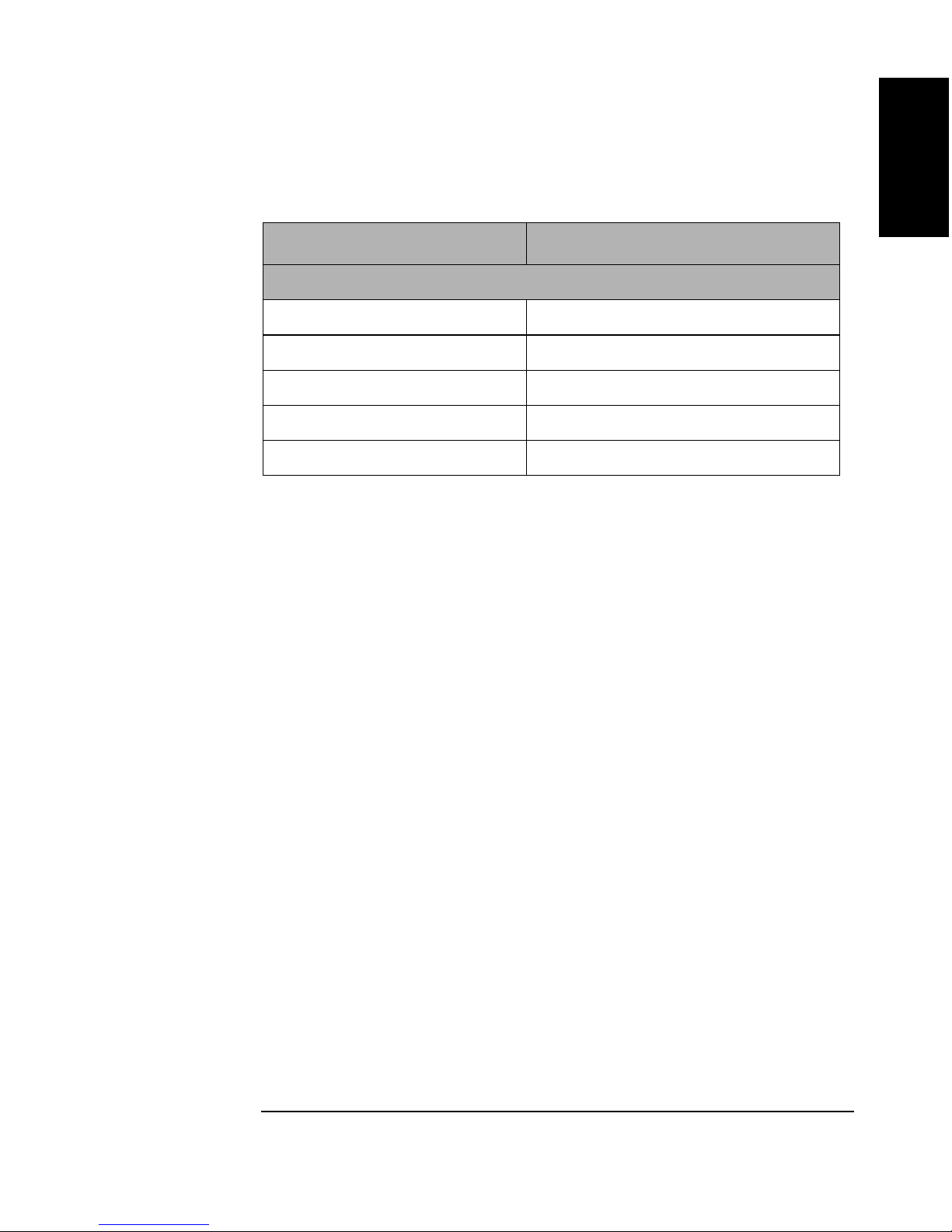
Table 1-1 Technical Specifications
Characteristics Description
Physical Characteristics
Height (cm, inches) 180.8, 71.2
Width (cm, inches) 87.6, 34.5
Depth (cm, inches) 73.4, 28.9
Net weight (kg, lbs)) 226.3, 498.8
Packaged weight (kg, lbs) 301.6, 665
Product Information
Technical Specifications
Information
Product
Chapter 1 1-5

Product Information
Environmental Specifications
Environmental Specifications
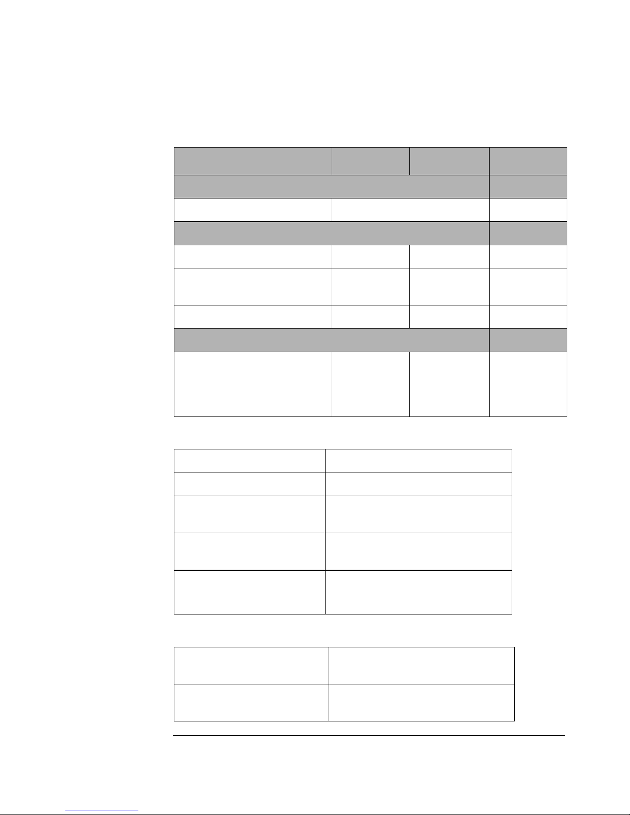
Table 1-2 Environmental Specifications
Characteristics Robotics Drive Media
Temperature (o C)
Operating 10 to 40 5 to 45 10 to 60
Non-operating w/o disk - 40 to 70 - 40 to 60 10 to 60
Max. Temperature
gradient (o C /hr)
Transportation - <14
consecutive days
Humidity, non-condensing (%)
Relative operating 10 to 90 5 to 90 10 to 80
Non-operating w/o disk 5 to 95 5 to 95 10 to 90
Maximum wet bulb (o C) 29 29 29
10 10 10
-40 to 60
Chapter 11-6

Table 1-2 Environmental Specifications
Characteristics Robotics Drive Media
Shock , non-operating (g/ms)
Product Information
Environmental Specifications
Information
Product
End use, handling,
150 / 3 25 / 11 760 mm
half-sine
Transportation,
30 / 523 30 / 742
trapezoidal (g/cm/s)
Vibration, 5-500 Hz range (g rms)
Operating, maximum
0.21 0.3 >0.21
acceleration (g rms)
Non-operating random
23
(g rms)
Non-operating, swept-sine
0.5 0.1
(g, 0-peak)
Altitude (meters, feet)
Operating 4,572 / 15,000
Non-operating 15,240 / 50,000
drop to
2mm
vinyl-cover
ed concrete
Acoustic emissions (dB - L noise power emission level)
Operating (dB - L noise ) 61.5
Idle 47
Chapter 1 1-7
Product Information
Environmental Specifications
Table 1-2 Environmental Specifications
Characteristics Robotics Drive Media
Particulates (µg/cm3)
Electrostatic discharge (kV)
Airgap (operating) 5 to 15 0 to 10
<200
Airgap (non-operating
survival)
Direct contact (operating) 0 to 4 0 to 4
Cooling requirements (CFM)
Table 1-3 Power Requirements
Line voltage (Vac) 100 - 127, 200-240
Line frequency (Hz) 50 - 60
Power consumption,
typical (Watts, BTU)
Power consumption
(Watts, BTU)
0 to 25 0 to 25
15
(bidirection
al through
drive)
300, 1023
340, 1,160
Current (amperes) 6 (120 V)
Table 1-4 Reliability
Mean swaps between
failure (MSBF) - robotics
Mean swaps between
failure (MSBF) -drive
5 (240 V)
2,000,000
750,000
Chapter 11-8

Table 1-4 Reliability
Product Information
Environmental Specifications
Information
Product
Mean time between
failure (MTBF) - robotics
(power-on hours
Mean time between
failure (MTBF) - drive
(power-on hours)
Mean time to repair
(hours)
Preventive maintenance none required*
Table 1-5 Product Certifications
Safety EN 60950/IEC 950
100,000
100,000
2
* for high-usage or zero
downtime installations, see the
Product Support Plan for
special preventative
maintenance schedules
UL 1950 listed or recognized
Electromagnetic emissions FCC Class “A”, CISPR 22,
Class “A”
Class “A” EN 55022/CISPR 22,
Level “A”; VCCI Level 2
Laser CDRH 21 CFR Chapter 1,
Subpart J IEC 825
Clearance Requirements
A minimum 70-80 mm (3 in.) is required behind the rear panel to allow
air to circulate.
Chapter 1 1-9

Product Information
Environmental Specifications
Figure 1-1 Clearance Requirements
A
(w)
B
(x)
(y)
(2)
(z)
Mailslot
• Figure A is usually in a row of peripheral cabinets.
— Rear (w) requires 56 cm (18 in.) for cooling and service.
— Front (z) requires 86 cm (34 in.) for operator access.
— Sides (x) and (y) can be adjacent to other cabinets; the service
panel (y) would be accessed by pulling the cabinet forward on it
wheels.
(1)
Mailslot
(3)
(4)
• Figure B orientation represents free standing or against a wall.
— Rear (1) requires 61 cm (24 in.) for service access.
— Sides (2) and (3) require 30.5 cm (12 in.) for service, operator
access, and cooling.
— Front (4) requires 61 cm (24 in.) for service and operator access,
plus additional space if the cabinet must be moved to access the
rear panel (1).
Location Requirements
Position the jukebox away from sources of particulate contamination
such as frequently-used doors and walkways, stacks of supplies that
collect dust, printers, and smoke-filled rooms.
Chapter 11-10

Product Information
Environmental Specifications
Responsibilities
Customer site preparation/verification and installation are the
customer’s or reseller’s responsibility; HP will perform the site
preparation/verification and/or installation on a time-and-materials
basis.
Information
Product
Chapter 1 1-11

Product Information
Environmental Specifications
Chapter 11-12

Installation
2 Installation
Chapter 2 2-1

Installation
Overview
Overview
This chapter gives information on the following topics:
• identifying controls and features
• connecting SCSI cables to the jukebox
• connecting the jukebox as the only peripheral
• connecting the jukebox with other peripherals
• connecting power
• configuring write verify
• default SCSI IDs in normal and LUN addressing
• moving and shipping the jukebox
Chapter 22-2
Identifying Controls and Features
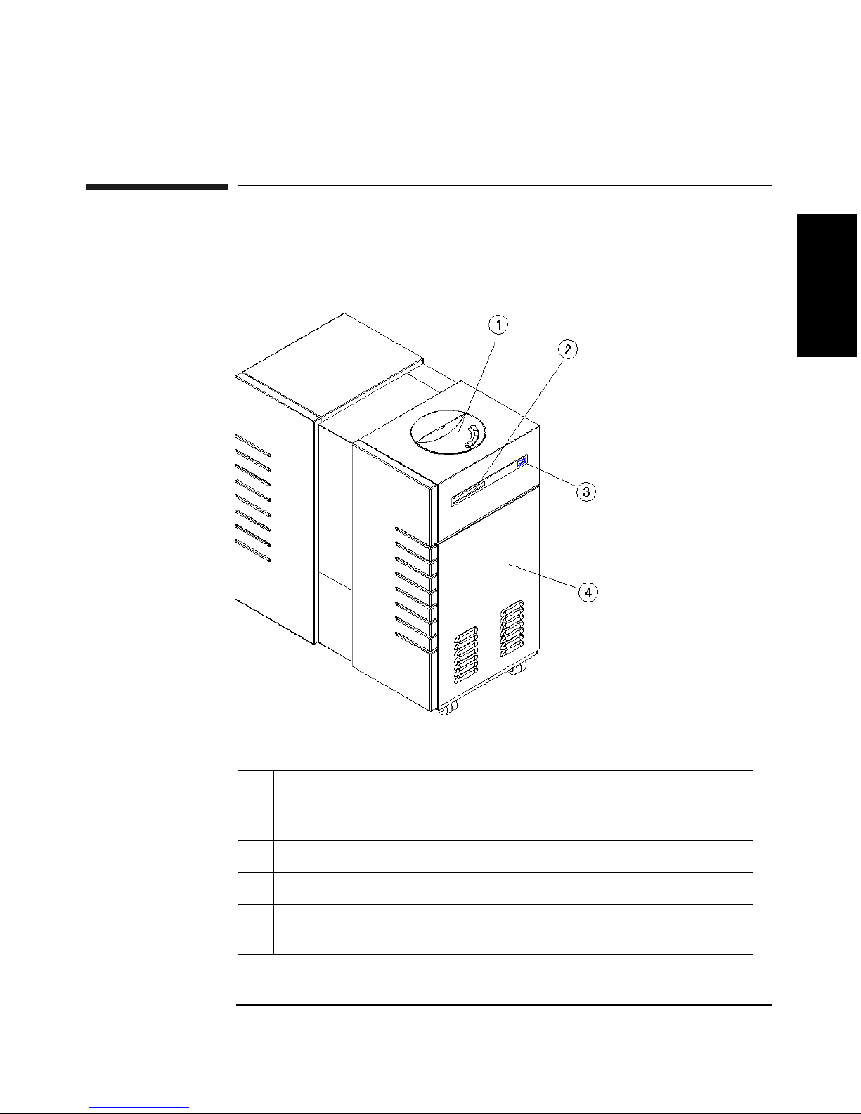
Identifying Controls and Features
Installation
Figure 2-1 Right Side
Installation
1Control
panel
2 Mailslot Used to load and eject optical disks.
3 Power switch Used to power the jukebox on and off.
4 Right access
panel
Chapter 2 2-3
Used to manually control and monitor
operation of the jukebox. A full description of
the controls and indicators is in Chapter 3.
A panel that covers access to the optical drives
and interposer PCA.
Installation
Identifying Controls and Features
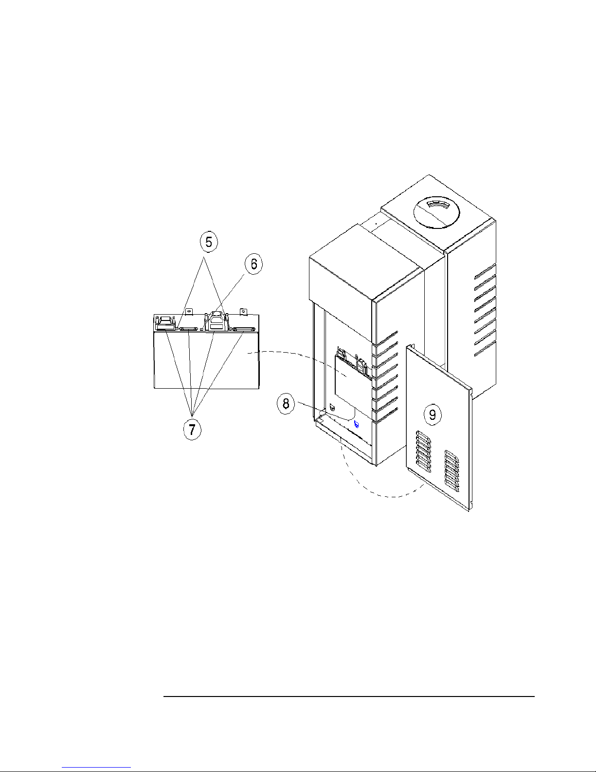
Figure 2-2 Left Side
Chapter 22-4
 Loading...