

Page 1

quick start guide
hp surestore
fc switch 6164
www.hp.com
Page 2

Notice
© Hewlett-Pack a rd C om pa n y, 2001. All rights rese r v ed .
Part number: A7326-90901
Edition: E0801
Hewlett-Packard Company makes no warranty of any
kind with regard to this material, including, but not
limited to, the implied warranties of merchantability and
fitness for a particular purpose. Hewlett-Packard shall not
be liable for errors contained herein or for incidental or
consequential damages in c o nn ectio n with the furnish in g,
performance, or use of this material.
This document conta in s p rop rie ta ry info rm at ion , whic h is
protected by copyr ight. No part of this document may be
photocopie d, reproduced, or translated into another
language without the prior written consent of
Hewlett-Packard. The i nformation contained in this
document is subject to change without notice.
All other brands, product or service names are or may be
trademarks or service ma rks of, and are used to identify
products of services of their respective owners.
Brocade Extende d Fabrics, Brocade Fabr ic Manager,
Brocade Fabric OS, Brocade Fabric Watch, Brocade
QuickLoop, Brocade Remote Switch, Brocade Web T ools,
and Brocade Zoning are hereafter referred to as Extended
Fabrics, Fabric Manager, Fabric OS, Fabric Watch,
QuickLoop, Remote Switch, Web Tools, and Zoning
respectively.
Safety notices
Any servicing , adjustme nt, mainte nance, or re pair must be
performed only by authorized service-trained personnel.
Format convention s
variable Indicates that you must supply a value.
Use, duplication, or disclosure by government is subject
to restrictions as set forth in subdivision (c) (1) (ii) of the
Rights in Technical Data and Computer Software Clause
at DFARS 252.227.7013.
Warranty
If you have any ques tions about the warranty for this
product, contact your d eal er or local Hewlett-Packard
sales representative.
Trademarks
Brocade, SilkWorm, Brocade Extended Fabrics, Brocade
Fabric Manage r, Brocade Fabric OS, Brocade Fabric
Watch, Brocade QuickLoop, Brocade Remote Switch,
Brocade Web Tools, and Brocade Zoning are tradema rks
or registered trademarks of Brocade Communications
Systems, Inc. in the United States and/or in other
countries.
output Denotes text displayed on the screen.
[ ] Indicates that the enclo sed element is
optional and may be left out.
{ } Indicates that you must specify one of the
listed options.
| Separates alternatives.
. . . Indicates a repetition of the precedi ng
parameter.
Denotes ideas for enhanced product usage.
Tip
Note Denotes significant concepts or ope rat ing
instructions.
CAUTION Denotes a hazard that can cause hardware or
software damage.
WARNING Denotes a hazard that can cause personal
injury or death.
2
Page 3

CONTENTS
Revision History . . . . . . . . . . . . . . . . . . . . . . . . . . . . . . . . . . . . . . . . . . . . 5
Updates . . . . . . . . . . . . . . . . . . . . . . . . . . . . . . . . . . . . . . . . . . . . . . . . . . . 5
Related Publications . . . . . . . . . . . . . . . . . . . . . . . . . . . . . . . . . . . . . . . . . 5
1 Overview . . . . . . . . . . . . . . . . . . . . . . . . . . . . . . . . . . . . . . . 7
2 Installing the Switch . . . . . . . . . . . . . . . . . . . . . . . . . . . . . . 9
Rack-Mount Safety Guidelines . . . . . . . . . . . . . . . . . . . . . . . . . . . . . . . . 10
Package Contents . . . . . . . . . . . . . . . . . . . . . . . . . . . . . . . . . . . . . . . . . . 11
Tools Required . . . . . . . . . . . . . . . . . . . . . . . . . . . . . . . . . . . . . . . . . . . . 13
Hardware Identification . . . . . . . . . . . . . . . . . . . . . . . . . . . . . . . . . . . . . 14
Installing the Switch . . . . . . . . . . . . . . . . . . . . . . . . . . . . . . . . . . . . . . . . 15
3 Setup . . . . . . . . . . . . . . . . . . . . . . . . . . . . . . . . . . . . . . . . . 33
System Components . . . . . . . . . . . . . . . . . . . . . . . . . . . . . . . . . . . . . . . . 33
Fibre Channel Cable Connections . . . . . . . . . . . . . . . . . . . . . . . . . . . . . 36
Initialize the Switch . . . . . . . . . . . . . . . . . . . . . . . . . . . . . . . . . . . . . . . . 37
Power Supply . . . . . . . . . . . . . . . . . . . . . . . . . . . . . . . . . . . . . . . . . . . 33
Fabric Operating System . . . . . . . . . . . . . . . . . . . . . . . . . . . . . . . . . . 34
GBIC Modules . . . . . . . . . . . . . . . . . . . . . . . . . . . . . . . . . . . . . . . . . . 34
3
Page 4

Serial Port and Ethernet Connections . . . . . . . . . . . . . . . . . . . . . . . . . . . 38
Ethernet Connection . . . . . . . . . . . . . . . . . . . . . . . . . . . . . . . . . . . . . 38
Serial Port Connection . . . . . . . . . . . . . . . . . . . . . . . . . . . . . . . . . . . . 39
Status Indicators . . . . . . . . . . . . . . . . . . . . . . . . . . . . . . . . . . . . . . . . . . . 40
4 Installing Software . . . . . . . . . . . . . . . . . . . . . . . . . . . . . . 43
Installing Fabric Manager . . . . . . . . . . . . . . . . . . . . . . . . . . . . . . . . . . . . 43
Requirements . . . . . . . . . . . . . . . . . . . . . . . . . . . . . . . . . . . . . . . . . . . 43
Installing Fabric Manager . . . . . . . . . . . . . . . . . . . . . . . . . . . . . . . . . 45
Launching Fabric Manager . . . . . . . . . . . . . . . . . . . . . . . . . . . . . . . . 53
Adding the Browser Pathnam e to the Properties File . . . . . . . . . . . . 54
Uninstalling Fabric Manager . . . . . . . . . . . . . . . . . . . . . . . . . . . . . . . 54
Installing Remote Switch . . . . . . . . . . . . . . . . . . . . . . . . . . . . . . . . . . . . 55
Installing Through Telnet . . . . . . . . . . . . . . . . . . . . . . . . . . . . . . . . . 55
Installing Through Web Tools . . . . . . . . . . . . . . . . . . . . . . . . . . . . . . 56
Installing Extended Fabrics . . . . . . . . . . . . . . . . . . . . . . . . . . . . . . . . . . 57
Installing Through Telnet . . . . . . . . . . . . . . . . . . . . . . . . . . . . . . . . . 57
Installing Through Web Tools . . . . . . . . . . . . . . . . . . . . . . . . . . . . . . 58
5 Diagnostics . . . . . . . . . . . . . . . . . . . . . . . . . . . . . . . . . . . . 61
Diagnostic Tests . . . . . . . . . . . . . . . . . . . . . . . . . . . . . . . . . . . . . . . . . . . 62
Error Messages . . . . . . . . . . . . . . . . . . . . . . . . . . . . . . . . . . . . . . . . . . . . 63
6 Specifications . . . . . . . . . . . . . . . . . . . . . . . . . . . . . . . . . . 65
General . . . . . . . . . . . . . . . . . . . . . . . . . . . . . . . . . . . . . . . . . . . . . . . . . . 65
Environmental . . . . . . . . . . . . . . . . . . . . . . . . . . . . . . . . . . . . . . . . . . . . . 66
Dimensions . . . . . . . . . . . . . . . . . . . . . . . . . . . . . . . . . . . . . . . . . . . . . . . 67
Power Supply . . . . . . . . . . . . . . . . . . . . . . . . . . . . . . . . . . . . . . . . . . . . . 67
Product Regulatory Information . . . . . . . . . . . . . . . . . . . 69
4
Quick Start Guide
Page 5

Revision History
August 2001 First release.
Updates
For the most current technical support information for the fc-Switch 6164,
visit the HP web site lo cated at:
http://www.hp.com
Firmware and software updates are found on the HP web site at:
http://www.hp.com
For information ab out produ ct avai labil ity, configurat ion, and co nnecti vity,
consult your HP account representative.
Related Publications
Related product information can be found in the following publications.
Those publications with part numbers are provided as printed copies with
your product. The HP Surestore FC Switch 6164 Documentation CD
contains all publications listed in the table below and is also provided with
your product.
Title Part Number
HP Surestore FC Switch 6164 Documentation
CD
HP Surestore FC Switch 6164 Installation and
Reference Guide
Distributed Fabrics User’s Guide, version 2.2 Available only on CD
Fabric OS Reference Manual, version 2.4 Available only on CD
Fabric Wa tch User’s Guide, versi on 2.2 Available only on CD
MIB Reference Manual, version 2.3 Available only on CD
A7326-11011
A7326-90902
5
Page 6

Title Part Number
QuickLoop User’s Guide, version 2.3 Available only on CD
Web Tools User’s Guide, version 2.3 Available only on CD
Zoning User’s G uide, version 2.2 Available only on CD
For information about Fibre Channel standards, visit the Fibre Channel
Association web site, locat ed at
http://www.fibrechannel.com.
6
Quick Start Guide
Page 7

1
OVERVIEW
The HP Surestore FC Switch 6164 provides a 64-port ent erpri se-cl ass fi bre
channel switching solution for any-to-any connectivity requirements in a
Storage Area Network (SAN). The FC 6164 provides a cost- effective
means of meeting the large-port-count requirements of workgroups and
enterprises.
The FC 6164 is a rack-mountable solution, comprised of a chassis and six
fully integrated Silkworm 2250 switch modules, with preconfigured
inter-switch link (ISL) fibre optic cables and enhanced management
software. The FC 6164 includes Fabr ic Manager , a management application
that provides a centralized view of the integrated switch modules to
simplify administration and maintenance.
Using this preconfigured, stand-alone fabric as a building block of larger
fabrics, you can sca le your st orage envi ronment as n eeded while leveragi ng
your existing server and storage infrastructure.
7
Page 8

8
Quick Start Guide
Page 9

INSTALLING THE SWITCH
This chapter provides the step-by-step instructions for installing the FC
Switch 61 64 in either a HP rack or a Compaq/Rit tal 19-inch rack.
2
Note
was installed at an HP inte grati on cente r prior to sh ipme nt. However, Steps
16 and 17 (assembling and installing the plenum) and Step 19 (installing
the switch door) must be performed for factory-integrated switches (see
pages 29 and 32).
Most of the steps in this procedure are unnecessary if the FC 6164
9
Page 10

Rack-Mount Safety Guidelines
In a rack-mount installation, follow these safety guidelines:
• When installing a switch in a closed or multi-rack assembly, make
certain the air te mper ature, measured a t th e front panel, doe s not exce ed
40° C during operation.
• Ensure that the airflo w available to the switch is at least 300 cfpm .
• Verify the supply circuit, line fusing, and wire size are adequate. Refer
to the switch’s nameplate for its p ower requirements.
• Verify that all equipment installed in the rack has a reliable ground
connection. Do not rely on conn ection to a branc h circuit , such as powe r
strips.
• Route and support the power cord to ensure that it does not become
crimped or damaged a nd to preve nt it from interfering with other
equipment and cabling installed in the rack.
• The FC 6164 weighs approximately 200 pounds. A lift is required to
move and position the switc h safely, and at lea st two people ar e require d
to lift and position the switch onto the lift. Two or more people are also
required to move the switch from the lift into the rack and when
positioning the switch in the rack. Move the switch chassis slowly and
carefully at all times, and continue supporting it until it is correctly
positioned on the rail tray and fastened t o t he r ac k. Use extreme caution
when handling or transporting the switch to prevent injury to personnel,
damage to the switch, and/or damage to the rack and other equipment
mounted in it.
10
Quick Start Guide
Page 11
Package Contents
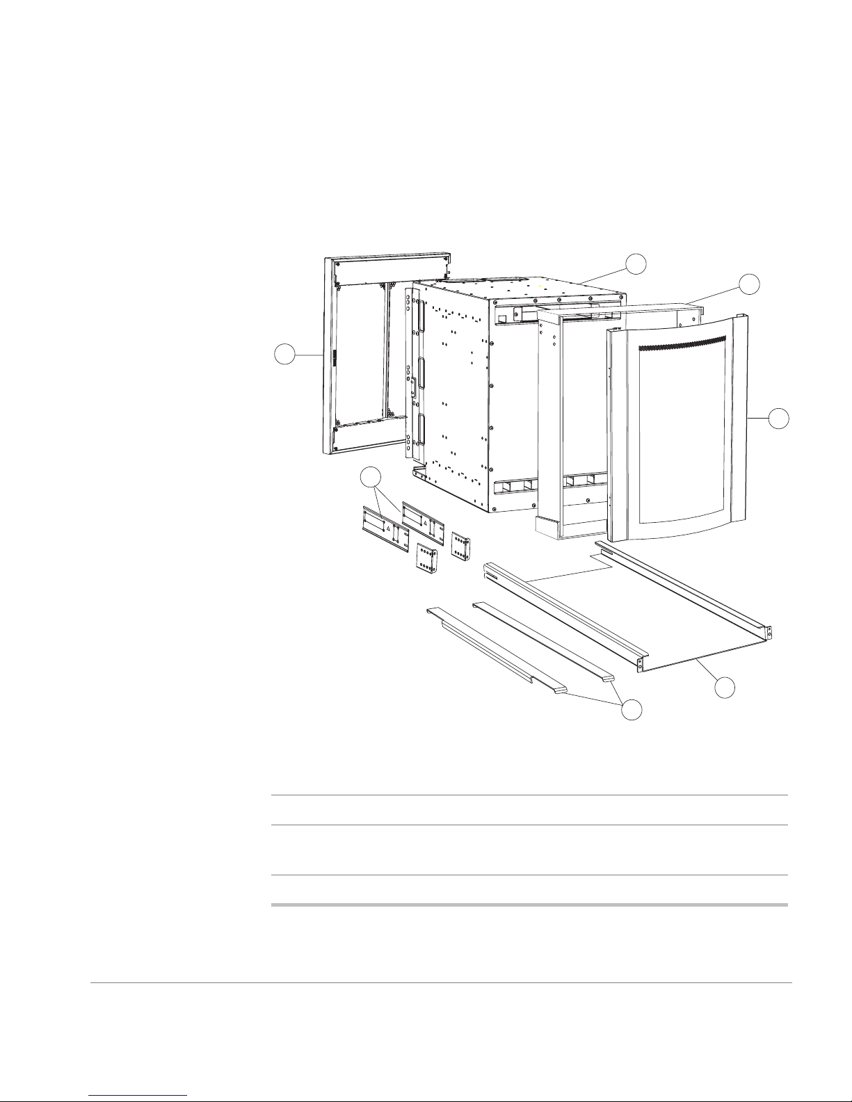
Figure 1 shows the major items contained in the FC 6164 shipping
carton(s). Table 1 lists the contents of the shipping carton.
G
A
B
C
F
F
Figure 1. Major Items Contained in the Shipping Carton(s)
Table 1. Contents of the Shipping Carton(s)
ASwitch
B Plenum kit (4 rectangular sheets of Lexan with 6 adhesive strips
C Front bezel (HP P/N A7326-40001)
Installing the Switch
D
E
pre-attached) (HP P/N A7326-87903)
11
Page 12

Table 1. Contents of the Shipping Carton(s) (continued)
D Rail Tray kit (Rail tray, 2 brackets, 2 M5 Tinnerman nuts, 4 M5 torx
screws) (HP P/N A6534-60016)
E Shim plates (2 ea. HP P/N A7326-87904)
F Rack-Mount Bracket set (2 Rack-Mount brackets)
(HP P/N A7326-87901)
G Switch door (part of Accessory kit [HP P/N A7326-70001], which
also includes: software CD, docu mentation C D, and seri al cable)
H Miscellaneous hardware: (not shown) (HP P/N A7326-87905)
Note: The hardware in the standard hardware package (unmarked plastic bag)
is required to install the switch in an HP rack. Some of the hardware in the
standard hardware package and the hardware in the Compaq/Rittal hardware
package is required to install the switch in a Compaq/Rittal rack.
Standard hardware package
8 #8-32 x .375-inch (.3125) flat-head screws w/patchlock
8 M5 torx screws with lock washers
6 M5 Tinnerman nuts
4 1/4-20 x 1/2-inch Phillips pan-head screws with lock washers
Compaq/Rittal hardware package
6 #10-32 Tinnerman nuts
6 #10-32 x 5/8-inch Phillips pan-head screws with captive lock washers
6 spacers
4 1/4-inch flat wash e r s
4 M5 flat washers
Note
A package containing two mounting rails may be included with the
switch. These rails are not used and can be discarded.
12
Quick Start Guide
Page 13

Tools Required
The following tools are required to install the switch:
• #2 Phillips screw driver
• T20 torx screwdriver
• Genie lift (to transport switch); for information on the li ft, see:
http://www.genielift.com/ml-series/ml-1-2.html
or
http://slick2.atl.hp.com/ceworld/siteservices/tools/genie/genielift_ordering.htm
Installing the Switch
13
Page 14

Hardware Identification
Figure 2 contains drawings and descriptions of the hardware used when
installing the FC 6164 in an HP rack or a Compaq /Ri tt al rack. Use this key
to help identify the hardware specified in the installation procedure in this
chapter.
#8-32 x .375-inch flat-head Phillips screw
M5 Torx screw with captive lock washer
M5 Tinnerman nut
1/4-20 x 1/2 inch Phillips screw and washer
14
#10-32 Tinnerman nut
#10-32 X 5/8-inch pan-head Phillips screw
Spacers for Compaq/Rittal racks
1/4-inch flat washer
M5 flat washer
Figure 2. Hardware Key
Quick Start Guide
Page 15
Installing the Switch
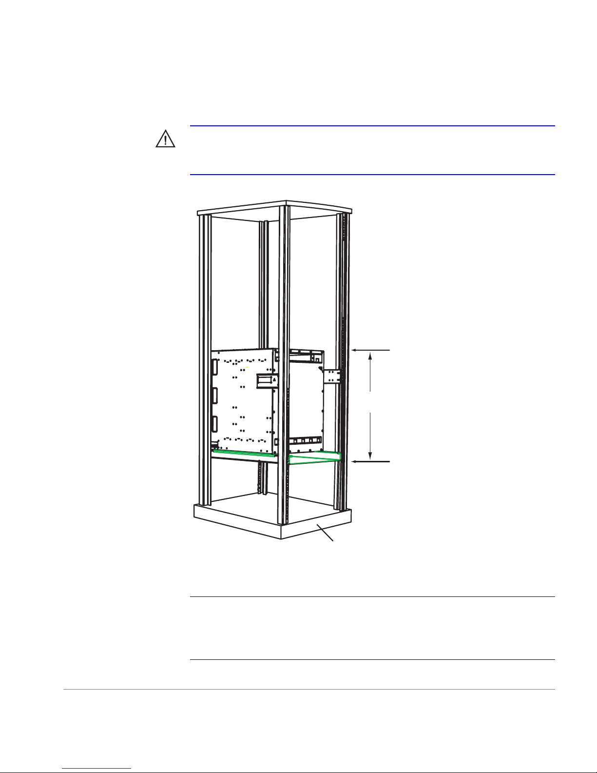
WARNING
Mount the switch as low as possible in the rack to ensure that
the weight of the switch does not make the rack unstable. 15 Rack Units
(RUs) are required (see Figure 3).
Back
of
switch
15 RU
Figure 3. Switch Mounted Back-to-Front and Low in the Rack
CAUTION
of the rack. When the switch is mounted this way, the air flows throu gh t he
switch in the same direction as it does through the other equipment in the
rack (see Figure 3).
Installing the Switch
Front of rack
The switch must be installed with the front end facing the back
15
Page 16

Note
In these inst ruc ti ons , the 15 RUs used to mount the switch ar e called
RU-1 through RU-15 (see Figure 3); RU-1 is the lowest of the 15 RUs.
1. Check the contents of the shipping carton and the kits within the carton
to verify that all of the required parts and hardware are available (see
Figure 2, Table 1, and Figure 3).
2. Choose a mounting l ocation in the rack f or the switch (see the W ARNING
at the beginning of this section and Figure 3).
3. Install the rail tray in the rack:
a. Locate the lowest RU of the 15 you chose for mounting the switch
(this is RU-1).
b. Attach the rear rail-tray brackets to the r ear rack uprights at RU-1:
For an HP rack, use one M5 torx screw for each bracket (see Figure 4).
For a Compaq/Rittal rac k, insert spacers in th e upper and lower hol es
where the brackets are to be mounted, position the brackets on the
spacers, and use one M5 torx screw with captive lock washer and two
M5 flat washers to attach each bracket (see Figure 4).
16
Quick Start Guide
Page 17
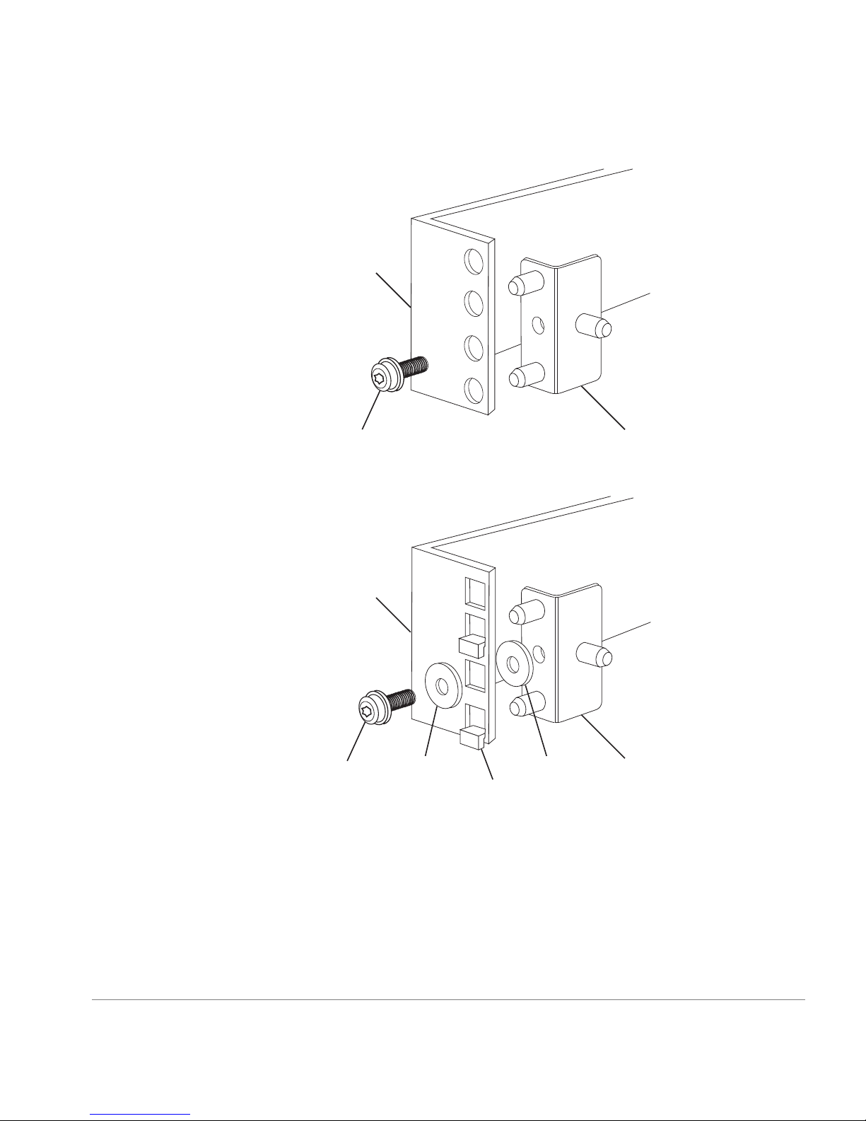
HP rack
M5 Screw
with attached
lock washer
Compaq/Rittal
rack
M5 Screw
with attached
lock washer
Figure 4. Installing the Rear Rail-Tray Brackets
M5
flat
washer
Spacer
M5
flat
washer
Rear Tray
bracket
Rear Tray
bracket
Installing the Switch
17
Page 18
Note
When installing the rail tray in a Compaq/Rittal rack, ignore the
mounting instructions on the label attached to the rail tray (some rail
trays do not have this label).
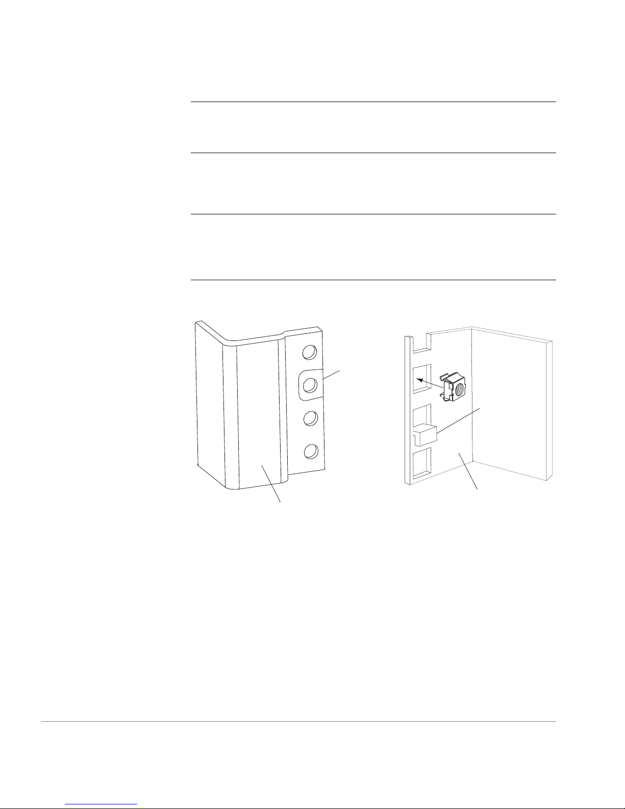
c. Install Tinnerman nuts for the top hol es of RU-1 in both of the r ack’s
front uprights (see Figure 5).
Note
The Tinnerman nuts used for the two types of racks (HP and
Compaq/ Rittal) are o f different styles and diffe rent sizes. Refer to
Figure 3 and Figure 5 to identify the correct Tinnerman nut to use with
the rack you are installing the switch in.
Tinnerman
nut
Spacer
Inner surface of
Outer surface of
HP rack
Compaq/Rittal
rack
Figure 5. Installing Tinnerman Nuts and Spacers on the Front Uprights
18
Quick Start Guide
Page 19
d. For a Compaq/Ritt al rack, insert spacers in the holes immediately
below the Tinnerman nuts you inserted in Step 3c (see Figure 5).
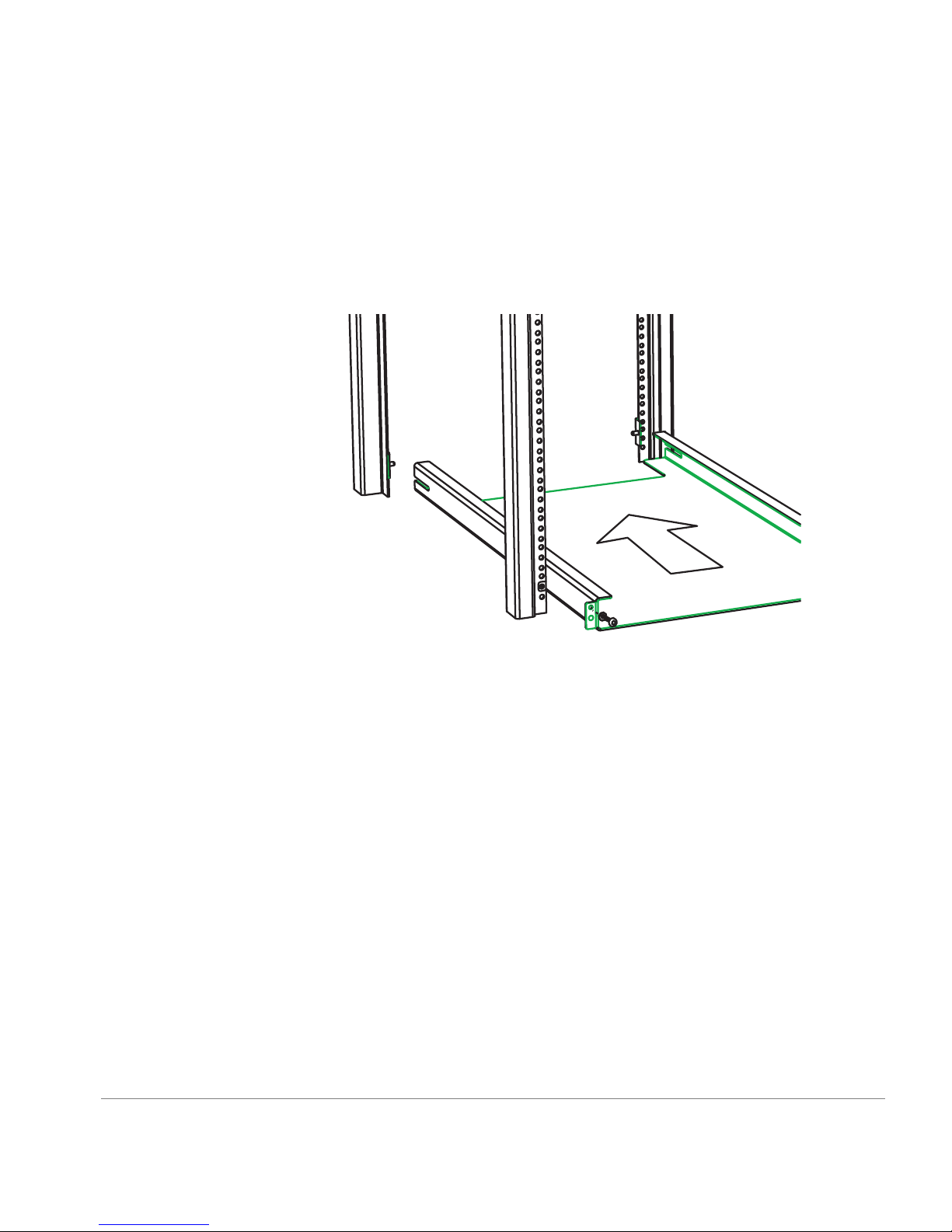
e. Orient the rail tray as shown in Figure 6, and insert it into the rack
from the front. The slots in the sides of the rail tray must slide over
the posts on the re ar ra il-t ray br acket s, and t he pos ts on the rail tra y’s
front mounting flanges must be inserted in the center holes of RU-1.
Installing the Switch
Figure 6. Inserting the Rail Tray in the Rack
f. Insert M5 torx screws through the top holes in both of the rail tray
mounting flanges. The screws pass through the holes in the rack
uprights and thread into the Tinnerman nuts you installed on the
uprights in Step 3c. Tighten the screws.
19
Page 20
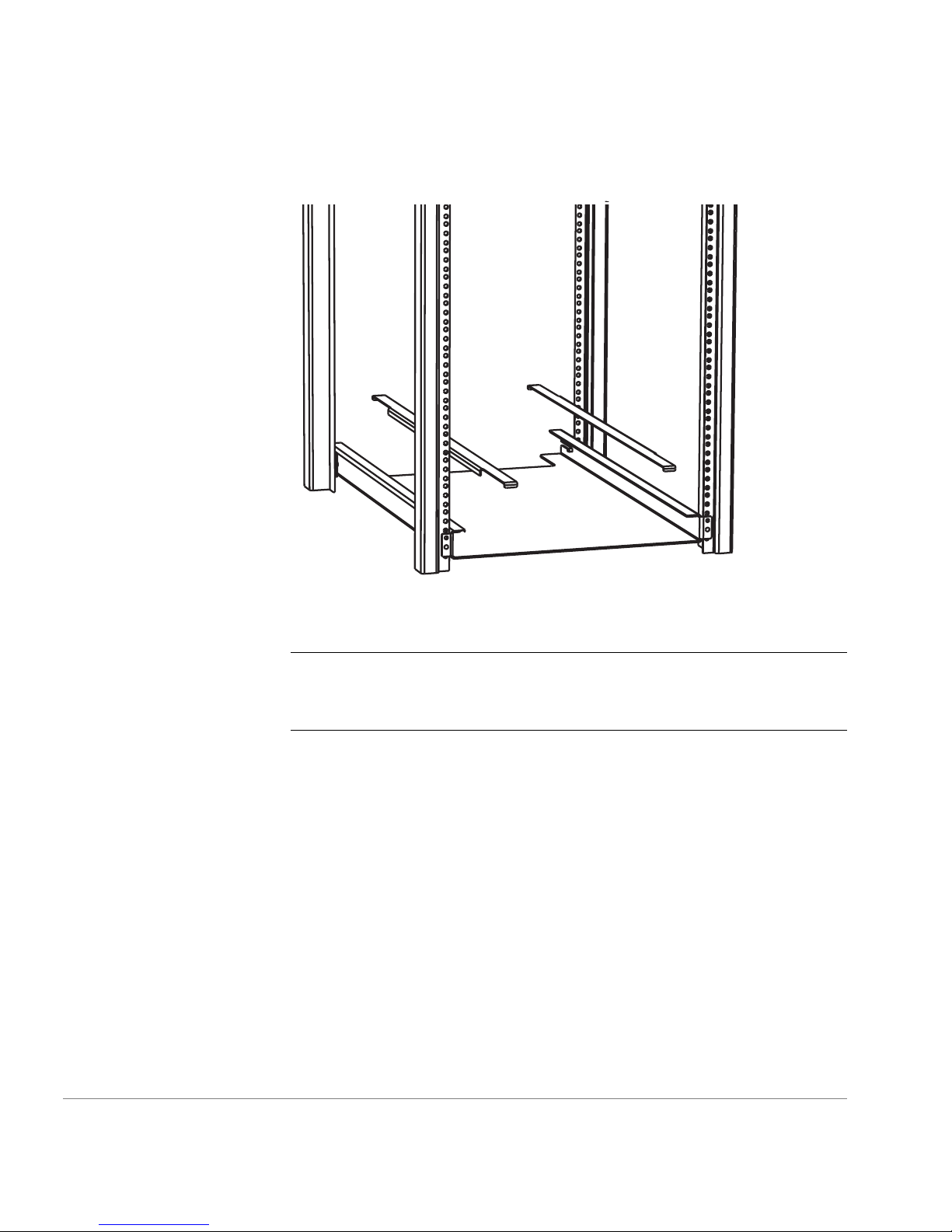
4. Place a shim plate on each side of the rail tray (see Figure 7).
Figure 7. Placing the Shim Plates on the Rail Tray
CAUTION
The shim plates must be placed on top of both sides of the
rail tray to prevent mis alignment b etween the mounting holes in the
switch flanges and the holes in the rack uprights.
20
Quick Start Guide
Page 21
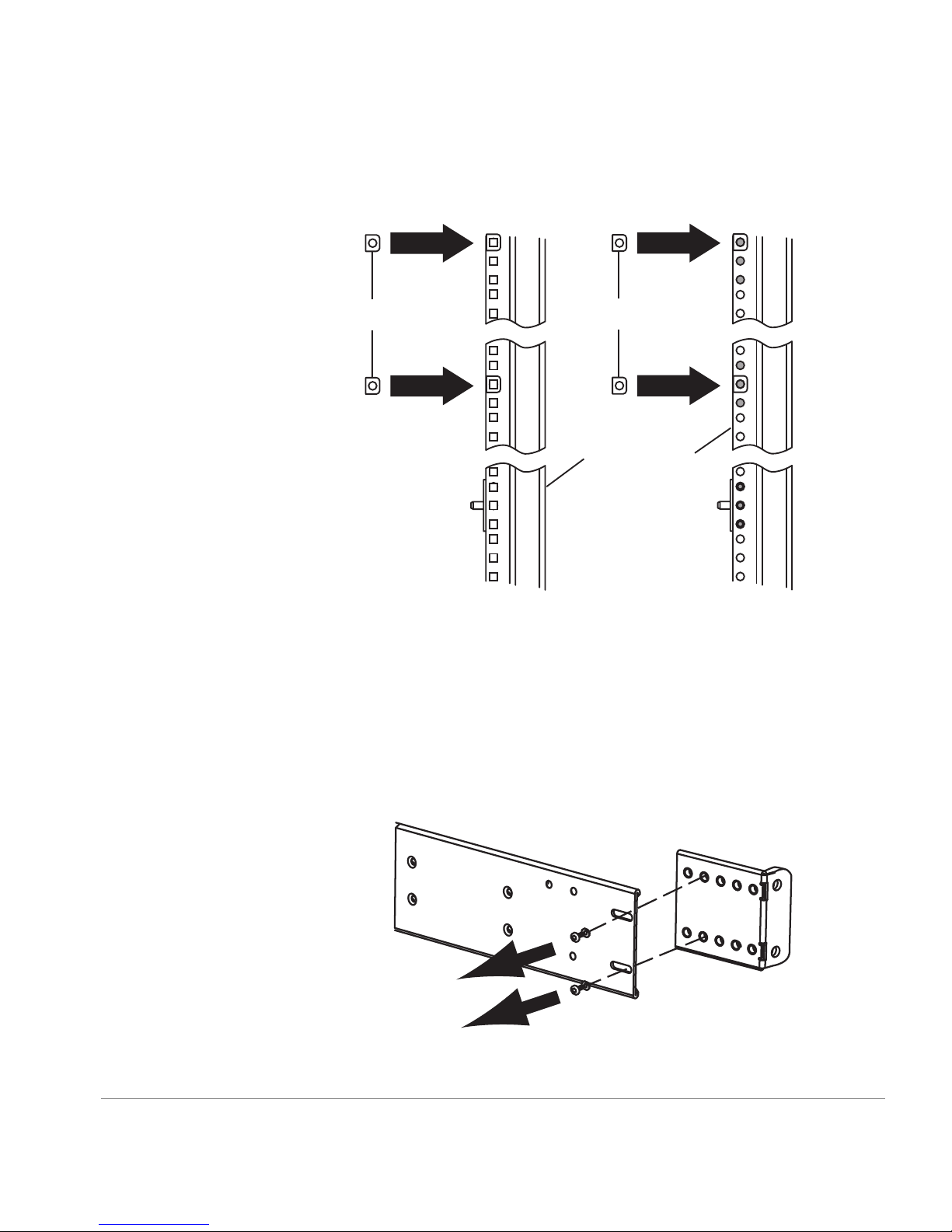
5. Insert T inner man nuts ont o the cent er holes of RU-5 a nd the top h oles of
RU-12 in both of the rack’s rear uprights (see Figure 8).
12
11
M5 Tinnerman nuts
5
4
#10-32Tinnerman nuts
Rack uprights
1
HP Rack Rittal Rack
Figure 8. Installing Tinnerman Nuts in RU-5 and RU-12
12
11
5
4
1
Installing the Switch
6. Install the rack-mount brackets on the switch:
a. The rack-mount b rackets consist of a stati onary plate and an adjusta ble
plate that are attache d to each other with two s crews. Remove the
screws that attach th e adjustable plates t o the stationary plate s. Set the
screws and the adjustable plates aside for later use (see Figure 9).
Figure 9. Separating the Rack-Mount Bracket Plates
21
Page 22
b. Use four #8-32 x 5/1 6-inch Phil lips flat -head screws to moun t one of
the stationary p lat es ont o ea ch side of the switch. The plates must b e
oriented so that the end of the plat e that has the slot ted holes protrude s
past the back of the switch, and if the plate has arrows stamped into
it, the arrows must point up (see Figure 10). Do not tighten the screws
fully at this time.
Note
Some stationary plates have arro ws sta mped into th em, and som e
do not. The arrow determines which side of the switch the plate must be
mounted on. If the stationary plates provided with the switch do not
have arrows, they can be mounted on either side.
Figure 10. Mounting the Rack-Mount Bracket Stationary Plates to the Switch
22
Quick Start Guide
Page 23

7. If you have adequate access to the back of the rack to insert the switch
from the back, sk ip Steps 8, 9, and 10. If yo u do not have a dequate access
to the back of the rack, proceed with Step 8.
Note
If you cannot insert the swi tch int o t he r ack fr om the back , you must
remove several pieces of hardware from the sides of the switch at the front
end as described in Steps 8, 9, and 10. If you have adequate access to insert
the switch into the rack from the back, you can skip these steps.
8. Remove the four #6-32 x 1/4-inch flat-he ad screws that attach each of the
two hinge plates to the left side of the switch at the front end (see
Figure 11). Set the scr ews and the hinge plates aside for later use.
x 8
Installing the Switch
Figure 11. Removing the Hinge Plates from the Switch
23
Page 24

9. Remove the two screws that attach the latch plate to the right side of the
switch at the front, an d remove the latch plate (see Figure 12). Set the
latch plat e and the screws aside for later use.
Note
The latch plate fits through a cutout in the rack-mounting flange on
the right side of the switch.
Rack-mounting
flange
Latch plate
Figure 12. Removing the Latch Plate and the Mounting Flanges
10.Remove the eight #10-32 Phillips screws that attach each of the
rack-mounting fla nges to t he sides o f the swit ch at th e front, a nd remove
the rack-mountin g flanges (see Figure 12). Set the rack-mounti ng flanges
and the screws aside for later use.
24
Quick Start Guide
Page 25

WARNING
If the rack you are mounting the switch in is on wheels,
make sure the l eveli ng feet are down or the wheels are lock ed to pr event
the rack from moving while you are installing the switch. Failure to
prevent the rack from moving could result in injury to personnel and/or
damage to the switch, the rack, or other equipment.
11.Insert the switch in the rack:
WARNING
The FC 6164 weighs approximately 200 pounds. A lift is
required to move and position the switch safely, and at least two people
are requi red to lift and position the switch ont o the lift. Two or more
people are also require d to move the switch from the lift into the rack
and when positioning the switch in the rack. Move the switch chassis
slowly and carefully at all times, and continue supporting it until it is
correctly positioned on the rail tray and fasten ed to the rack. Use
extreme caution when handling or transporting the switch to prevent
injury to personnel, damage to the switch, and/or damage to the rack and
other equipment mounted in it.
a. Place the switch on a lift. If you are instal ling the switch from the f ront
of the rack, orient the switch so t hat its front end faces the front of the
rack. If you are i nstal ling t he s witch f rom the bac k of th e rack, ori ent
the switch so that its back end is at the edge of the lift. (The switch
must be installed so the front of the switch faces the back of the rack.)
b. Position the lift close to the rack, and raise it until the bottom of the
switch is even with or very slightly above the t op surfaces of the shim
plates that you positioned on top of the rail tray in Step 4.
Installing the Switch
c. Carefully slide the switch from the lift onto the shim plates on the rail
tray.
d. Position the switch so that its front end protrudes out the back of the
rack approximately six inches.
25
Page 26

12.If you in serted the switch into th e rack from th e back, skip this step.
Reinstall the removed hardware:
a. Use the 16 #10-32 Philli ps screws you removed in Step 10 to re-attach
the rack-m ounting flan ges to the switch (see Figure 12).
b. Use the two screws you remove d in Step 9 to re-attach the latch plate
(see Figure 12). Make sure that there is a gap of approximately
3/16-inch between the edges of the latch plate and the edges of the
cutout in the rack-mounting flange.
c. Orient the hinge plates so th at th e sides tha t have the loo ps face eac h
other (see Figure 13). Use the eight #6-32 x 1/4-inch f lat-head screws
you removed in Step 8 to re- att ac h the hinge plates to the left side of
the switch at the front end (see Figure 11).
Loops
Figure 13. Orienting the Hinge Plates Prior to Reinstallation
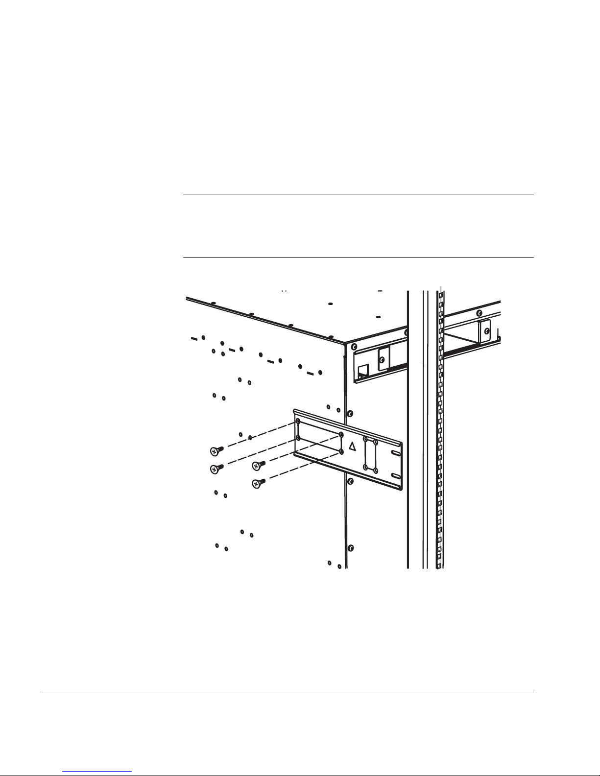
13.Re-attach the rack-mount bracket adjustable plates:
a. From t he front of the rack, slide the switch forward a short distance.
b. Insert one of the a djustable plates i nto one of the stati onary plates (see
Figure 14).
26
Quick Start Guide
Page 27

Figure 14. Re-attaching the Rack-Mount Bracket Adjustable Plates
c. Insert the scr ews yo u remove d in Ste p 6a thro ugh the slott ed holes in
the stationary plate and into the second set of threaded ho les in the
adjustable plate from the rack-mounting flange (see Figure 14). Do
not tighten the screws at this time.
d. Repeat Steps b and c for the rack-m ount bra cket on th e opposit e side
of the switch.
e. Move t he switch forward in the rack as far as it can go. T he amount
of movement is limited by the rack-mount bracket adjustable plates
contacting the rack uprights.
Installing the Switch
WARNING
The FC 6164 weighs approximately 200 pounds.Two or
more people are requi red when positioni ng the switch i n the r ack. Mo ve
the switch chassis slowly and carefully at all times, and continue
supporting it until it is correctly positioned on the rail tray and fastened
to the rack. Use extreme caution when handling or transporting the
switch to prevent inju ry to personnel, damage to the switch, and/or
damage to the rack and other equipment mounted in it.
f. Put flat washers on four 1/4-20 scre ws with captive l ock washers, an d
insert the screws through the holes in the rack uprights and into the
threaded holes in the flanges of the rack-mount bracket adjustable
plates (see Figure 14). Do not tighten the screws at this time.
27
Page 28

14.From the back of the rack, insert fou r #10-32 x 5/8-inch Phil lips pan-head
screws with captive lock washers through the holes in the rack-mount
flanges attached to the front end of the switch and i nto the Tinnerman nut s
you placed in the ra ck in Step 5 (see Figure 8 and Figure 15). Tighten the
screws fully.
Note
For an HP rack, you may have to adjust the positions of the
Tinnerman nuts to get them to align properly with the holes in the rack
uprights. If neces sary, use a screwdriver bl ade inserted through the hole s
in the rack uprights to reposition the Tinnerman nuts.
Figure 15. Attaching the Rack-Mount Flanges to the Rack
28
Quick Start Guide
Page 29

15.Fully tighten the screws that attach the rack-mount bracket adjustable
plates to rack uprights, then fully tighten the screws that attach the
adjustable plates to the stationary plates an d the screws that attach the
stationary plates to the switch chassis (see Figure 14).
16.Assemble the plenum:
a. Position the bottom pane l of the plenum on a flat surfa ce with the two
folded ends facing up (see Figure 16).
Adhesive
strips
Adhesive
strips
Bottom of
plenum
Adhesive
strips
Figure 16. Assembling the Plenum
b. Remove the paper backing from one of th e adhe sive strips on one of
the plenum side panels, and carefully position the side panel against
the inner surface of one of the folded ends of the bottom panel (see
Figure 16). Press the side panel firmly against the upright end of the
bottom panel to ensure that the adhesi ve strip on the side pan el makes
full contact wit h the end of the bottom panel. Y ou can use a s crewdriver
handle to increase the pressure you apply when joining the parts.
c. Repeat Step 16b for the other side panel.
d. Remove the paper b acking from the adhesiv e strips on the upper ends
of both plenum side panels.
Installing the Switch
29
Page 30

e. Carefully position the plenum top panel over the side panels so that
the folded ends of the top panel fa ce down and ar e outside of the side
panels.
f. Wit h the top panel aligned with the side panels, press one of the side
panels firmly against the inner surface of the folded end of the top
panel to ensure that the adhesive strip on the side panel makes full
contact with the folded end of the top panel. Re peat this step for the
other side panel.
17.Install the plenum in the rack:
a. Remove the paper backing from the two a dhesive strips on th e bottom
surface of the plenum.
b. Position the plenum against the back of the switch and slide it down
until the adhesive strips on the underside of the plenum contact the
shim plates that are on top of the rail tray (see Figure 17).
Back
of
switch
Figure 17. Inserting the Plenum
c. Press down firmly on the bottom panel of the plenum above the
adhesive strips t o ensure that the adhesive strips make full contact with
the shim plates on top of the rail tray.
30
Quick Start Guide
Page 31

18.Install the front bezel:
a. Orient the front bezel so that its outer surface is facing you.
b. Align the bottom end of the front bezel with the bottom edge of the
rail tray (see Figure 18). There are two alignment posts and two spring
clips on each s ide of th e bezel t hat grip the rack u prights and hold the
bezel in position. Each of the lower alignment posts fits into the second
unused hole above the front mounting flange on each side of the rail
tray.
Installing the Switch
Figure 18. Installing the Front Bezel
c. Press the sides of the bezel against the rack uprights until the bezel
snaps into place. Snap the bottom end in first and then the top end.
d. Inspec t the bezel to ensure that i t is installed so that its top edge is
aligned with the top su rface of the switch.
31
Page 32

19.Install the switch door:
a. Rotate the knobs on the switch door so that they are in the down
position and the springs are compressed.
b. Position the door so that the hinge pins are between the loops on the
hinge plates mounted on the switch (see Figure 13 and Figure 19).
Note
When you rotate the door to the closed position, the
spring-loaded hinge pins will snap into the loops on the hinge plates.
Figure 19. Installing the Switch Door
Note
be installed, and it must be kept closed during normal operation.
32
T o ensur e that the swit ch does not emi t RFI, the switch doo r must
Quick Start Guide
Page 33

System Components
Power Supply
The SilkWorm 2250 switch is ready to use once the unit is plugged in.
When the power cord is connected to the switch, the switch is powered on.
The 2250 switch meets IEC 61000-4-5 surge voltage requirements. See
Chapter 6 for specific in formation o n power requ irements for the switch.
3
SETUP
33
Page 34

AC Module
Figure 20. 2250 Switch
DB-9 port
GBIC port
10/100BaseT port
Note
The 2250 switch does not have a power switch. When the power
cord is connected to the switch, the switch is powered on.
Fabric Operating System
Included with the switch is the Fabric OS. The system provides a large
number of commands and libraries to manage real-time tasks. See the
Fabric OS Reference Manual, Version 2.4 for details.
GBIC Modules
The switch accommodates up to sixteen GBIC modules. All interfaces have
status lights visible from the front panel giving a quick, visual check of the
switch port’s status and activity.
GBIC modules supported are the short wavelength (SWL) and long
wavelength (LWL) fibre-optics.
34
Quick Start Guide
Page 35

If your installation requires installing less than sixteen GBIC modules, the
unused port positions are protected by a metal, spring-loaded door that
covers the opening.
SWL Fibre-Optic GBIC Module
The SWL fibre-optic GBIC module, with a bl ack SC connector, is based on
short-wavelength 850 nm lasers supporting 1.0625 Gbps link speeds. This
GBIC module supports both 50-micron and 62.5-micron, multi-mode fibre
optic cables up to 500 meters in length. Figure 21 shows a SWL GBIC
module.
Figure 21. Short-Wavelength Las er (SWL) Fib r e-O pti c GBIC Mod ule
Note
The SWL GBIC module uses a Class 1 laser, which complies with
the 21 CFR, subpart (J) as of the date of manufacture.
LWL Fibre-Optic GBIC Module
The LWL fibre-optic GBIC module, with a blue SC connector, is based on
long-wavelength 1300 nm lasers supporting 1.0625 Gbps link speeds. This
Setup
35
Page 36

GBIC module supports 9-micron single-mode fibre optic cables up to 10
kilometers. Figure 22 shows a LWL GBIC module.
Figure 22. Long-Wavelength Laser (LWL) Fibre-Optic GBIC Module
Fibre Channel Cable Connections
All network cable connections are to the switch’s front panel. All
recommended cabling supports the switch’s 1.0625-Gbps transfer rate, as
shown in Table 2.
Table 2. Cabling Connections
Cable type Cable Specification
SWL Fibre Optic Duplex SC plug connectors
Multi-mode fibre
50 µm core diameter
62.5 µm core diameter
125 µm cladding diameter duplex cable
LWL Fibre Optic Duplex SC plug connectors
Single-mode fibre
9 µm core diameter
125 µm cladding diameter duplex cable
Note
The switch is not designed to interoperate with devices using an
Open Fibre Control optical interface.
Maximum run
length
500 meters
1641 feet
10 Kilometers
32,808 feet
GBIC module
Optical Wavelength
780-860 nm
without open fibre
control (non-O FC)
1270-1350 nm
without open fibre
control (non-O FC)
36
Quick Start Guide
Page 37

Fibre cable connect ions are made to GBICs loc ated on the fron t panel of the
switch using standard dual SC plug connectors as shown in Figure 23.
Figure 23. Dual SC Fibre Optic Plug Connector
The connectors are keyed and must be inserted into the GBIC module
connector in proper alignment. In most cases, one of the two connector
plugs is a different color to aid in proper connector alignment.
Note
optic plug into the GBIC module as you may damage the connector, the
GBIC module, or both. Make certain the fibre surface is clean and free of
dust or debris before inserting the connector into the GBIC module.
Initialize the Switch
To initialize the switch:
1. Insert the GBICs into th e GBIC ports and connect the Fibre Channel cable
to the GBIC. This may be done before o r after the switch is initialized.
2. Connect the power cord to the AC module of the switch. The switch
automatically performs a Power On Self Test (POST). The POST will
take approximately 2.5 minutes.
Remove the protective plug from the GBIC. Do not force the fibre
Setup
37
Page 38

Note
If a switch boot failure occurs, the switch must be taken offline
for repair or replacement. Contact your switch supplier for assistance.
3. If the factory- set IP address is compatible with your network, connect th e
Ethernet connection.
Note
The factory-set IP address is: 10.77.77.77. The Subnet Mask is:
255.255.255.0.
4. If the factory-se t IP address is not compatible wit h your network, connect
the serial por t connect ion, then f ollow the pr ocedure to s et the IP a ddress
on page 39.
5. Monitor the status indicators for port status, see “Status Indicators” on
page 40.
If a malfunction occurs during POST, specific error messages are written to
the system error log and can be analyzed via a Te lnet session when the
POST session completes. If the malfunction prohibits the switch from
completing the boot process (fatal error), the swit ch stops the boot process.
If the switch does not fully boot, the switch prompt will not be displayed
when the serial port is connected.
Serial Port and Ethernet Connections
The 2250 switch contains a serial port for initial configuration and an
Ethernet connection for remote monitoring and testin g.
Ethernet Connection
An Ethernet connection must be es tablished to obtain access to the inte rnal
SNMP agent in the switch and local area network (LAN). Once the
connection is made, remote Telnet and Web access is made available. To
establish an Ethernet connection, connect to an existing Ethernet
10/100BaseT LAN via the front panel RJ45 connector.
Note
Ethernet cable.
38
Remove shipping plug from the Ethernet port before inserting
Quick Start Guide
Page 39

Serial Port Connection
The 2250 switch has a serial port for initial configuration of the IP address.
This port can also be used for service purposes. The serial port should not
be used during normal operation.
Note
Remove the dust cover fr om the s erial port bef ore inse rting the se rial
cable.
Note
Do not use the serial port during normal operation or for regular
maintenance. Remove the serial port cable and, using the dust cover
supplied with the switch, cover the port during normal operation of the
switch.
To set the IP address on the switch for normal Ethernet access, perform the
following initial procedure:
1. Attach the provi ded serial cab le between the serial port o n the switch an d
an RS-232 serial port on your l aptop or host computer . The cable is wir ed
with only pins 2, 3, and 5 wired straight through.
Note
If needed, the adapter can be removed to allow for RJ45 serial
connection to your host computer.
2. Turn on the switch and wait for the power on self test (POST) to complete.
POST is complete whe n all LED activity has stopped; this takes
approximately 2 minutes.
3. Disable all serial communication programs running on your computer,
4. Run a terminal emulation program such as Hyperterm on Windows
5. Configure the te rminal for 9600 Baud, 8 Data Bi ts, No Parity, 1 Stop Bit,
6. Press
7. If prompted, provide a log in and password. The default is logi n =
Setup
such as sy nc programs for a PDA .
95/NT, or TERM in a Unix environment.
and no flow control. Click OK.
Enter
to get a prompt.
and the password =
password
admin
39
Page 40

8. At the prompt, type the command
ipAddrSet
, then press
Enter
9. When prompted, provide the IP Address, Subnet mask, and Gateway
Address in the standa rd IP form of xxx.xxx.xxx.xxx.
Note
address.
10.When prompted type
11.Power down the switch and disconnect the serial cable (and adapter, if
12.Power up the switch. IP-based management (T elnet, SNMP , or W ebTool s)
13.Record the IP address on the label provided on the switch.
Status Indicators
Each port contains an LED that indicates the status for that port. Table 3
describes the status indicators and possible corrective actions.
Table 3. Status Indicators and Corrective Actions
LED Description Action
For now, only edit the Ethernet addresses, not the Fibre Channel
y
and press
Enter
to apply the new values.
used). Connect the switch to a 10/100BaseT Ethernet connection.
can now be accessed by using the newly defined IP address.
40
No light showing No light or signal carrier (no
module, no cable) for media
interface LEDs.
Steady yellow Receiving light or signal
carrier, but not yet online.
Slow yellow Disabled (result of diagnostics
or port Disable command).
Flashes every 2 seconds.
Fast yellow Error, fault with port. Flashes
every 1/2 second.
Steady green Online (connected with device
over cable).
Check media
connection.
No action required.
Reset at management
station.
Reset switc h.
No action required.
Quick Start Guide
Page 41

Table 3. Status Indicators and Corrective Actions (continued)
LED Description Action
Slow green Online, but segmented
(loopback cable or
incompatible switch ). Flashes
every 2 seconds.
Fast green Internal loopback (diagnostic).
Flashes every 1/2 second.
Flickering green Online and frames flowing
through port.
Interleaving green
Port is bypassed. Reset at management
and yellow
AC Module LE D Description
No light showing No power is being supplied to
the switch. Check power cord
connection to the switch.
Steady Green Receiving power. Switch is
online.
Check media
connection at both
ends.
No action required.
station.
Setup
41
Page 42

42
Quick Start Guide
Page 43

INSTALLING SOFTWARE
This chapter provides instructions for installing the following software:
• Fabric Manager
• Remote Switch
• Extended Fabrics
Installing Fabric Manager
Fabric Manager p rov ides a graphi cal inter face tha t allo ws the admini stra tor
to monitor and manage a fabric from a standard workstation. Fabric
Manager runs on the workstation and can be used to manage any switches
that have Fabric OS version 2.0 or later and We b Tools version 2.2 or later
installed (this documentation describes Web Tools version 2.3
functionality).
4
Requirements
The switch and computer workstation must meet specific requirements for
the correct installation and operation of Fabric Manager.
43
Page 44

Switch Requirements
Fabric Manager can be used to manage switches that meet the following
requirements:
• SilkWorm 2400, 2800.
• Fabric OS a2.4.1 or later versions of HP supported Fabric OS.
Fabric Manager can be used to manage switches with earlier versions,
but status and event information is not available.
• HP Surestore FC Switch 6164
Workstation Requirements
The follow ing items are required for the correct installation and operation
of Fabric Manager on the computer workstation:
• one of the following operating systems:
– Windows 2000
– Windows NT 4.0
• adequate RAM:
– 128 MB for fabrics of 21 switches or less
– 256 MB for fabrics containing more than 21 switches
• 10 MB of free disk space
• one of the following web browsers:
– Netscape Communicator 4.51 or later
– Internet Explorer 4.01 or later
Note
The browser must be specifically configured to work with Fabric
Manager. For information about how to do this, see “Configuring the
Web Browser” on page 45.
• Java™ plug-in version 1.2.2-007 or later
44
Quick Start Guide
Page 45

Installing Fabric Manager
Preparing to use Fabric Manager to manage your fabric requires the
following steps:
• installation of one of the supported web browsers on the workstation, if
not already installed
• configuration of the web browser for use with Fabric Manager
• installation of the required Java plug-in on the workstation, if not
already installed
• installation of Fabric Manager on the computer to be used as a
workstation
Installing a Web Browser
Install one of the foll owing browsers, if not already inst alled:
• Netscape Communicator 4.51 or later (available at
http://www.netscape.com
)
• Internet Explorer 4.01 or later (available at
http://www.microsoft.com
)
Configuring the Web Browser
Specific browser settings are required for the correct operation of Fabric
Manager with either Netscape Communicator or Internet Explorer.
Configuring Netscape Communicator
The web browser cache must be cleared after the installation of Fabric OS.
The browser can use local cache copies of jar files and image files to
improve performance (depending on options selected in the browser),
which can cause incorrect display.
To remove cached files from Netscape Communicator:
1. Select Edit > Preferences.
2. Click Advanced in the left text box to expand it, then click Cache.
3. On the Cache panel, click Clear Memory Cache.
4. Click Clear Disk Cache.
Installing Software
45
Page 46

5. Click OK.
6. Exit and relaunch the browse r.
Configuring Internet Explorer
Correct op eration of Fabric Manager with Internet Explorer requires
clearing the web browser cache after installation, and specifying the
appropriate settings for the browser refresh frequency and process model.
The browser cache must be cleared after the installation of Fabric OS. The
browser can use local cache copies of jar files and image files to improve
performance (depending on options selected in the browser), which can
cause incorrect display.
To remove cached files from Internet Explorer:
1. Select Internet Options from the View menu if using Internet Explorer
4.x, or from the Tools menu if using 5.x.
2. Select the General tab.
3. Click Delete Files... (under “Temporary Internet Files”).
4. Click OK.
5. Exit and relaunch the browse r.
Browser pages must be refreshed at every visit to ensure the correct
operation of the Switch Admin feature.
To set the refresh frequency:
1. Select Internet Options from the View menu if using Internet Explorer
4.x, or from the Tools menu if using 5.x.
2. Select the General tab and click Settings (under “Temporary I nternet
Files”).
3. Under “Check for newer versions of stored pages,” s elect “Every visit to
the page.”
The correct Browser Process Model must be selected.
46
Quick Start Guide
Page 47

To select the Browser Process Model (only required for Windows NT):
1. Select View > Internet Option s if using In tern et Expl orer 4.x, or Tools >
Internet Options if using Internet Explorer 5.x.
2. Select the Advanced tab and click to expand the Browsing category.
3. Under “Browsing,” select “Browse in a new process” if using Internet
Explorer 4.x, or “Launch browser windows in a separat e process” if using
Internet Explorer 5. x.
Installing the Java plug-in on the Workstation
A Java plug-in must be instal led on the works tation for the Fabri c Manag er
installer to function, and for Fabric Manager and Web Tools to operate
properly Windows 2000 and NT workstations require Java plug-in version
1.2.2-007.
To determine the version of the Java plug-in installed on Windows 2000 or
NT, and install the plug-in if necessary:
1. Launch the Java plug-in control panel by selecting Start > Programs >
Java plug-in Control Panel and turning on the Java console.
2. Launch the web br owser, enter the name or IP address of a switch running
Fabric OS a2.4.1 or later, and press
Enter
.
The switch launches the Java plug-in console, which displays the Java
plug-in version currently installed.
3. Determine whether the c orrect Java plug-in version is inst alled, and install
if necessary:
– If the correct version is installed, Fabric Manag er is ready for use.
– If no Java plug-in is installed, point the browser towards a switch
running Fabric OS a2.4.1 or later, follow the link to the Sun
Microsystems W eb site, and download the correct Java plug-in, then
double-click the downloaded file to install the plug-in.
– If an outdated version is cur re ntl y in stalled, uninstall it, relaunch the
browser, enter the address of a switch running Fabric OS a2.4.1 or
later , follow th e link to the Sun Web site, and download the new Java
plug-in.
Installing Software
47
Page 48

Installing Fabric Manager on the Workstation
The Fabric Manager 1.0 installation package includes the following items:
• ReadMe.txt file, providing product name, version, and late-breaking
news
• Java plug-in version 1.2.2-007
• FabricManager.Jar file, containing the required Java classes
• FabricManager.Properties file, containing configuration information
To install Fabric Manager 1.0:
1. Insert the Fabri c Manager 1. 0 CD-ROM in the CD dri ve of the compu ter
workstation.
The installer automatically launches.
If Fabric Manager is already installed on the computer, a window
displays to indicat e t his . If t his window displays, you can either exit the
installer and uninstall the existing version, or click Next to continue
with the installatio n.
Note
If you decide to cont inue wit h the i nst alla tion an d selec t the s ame
location, all existing files are overwritten, e xcept for the
FabricManager.Properties file, which contains the selections from the
previous installation, and is saved as FabricManager.Properties.old.
48
Quick Start Guide
Page 49

The Welcome window displays, providing product information and
version.
2. Click Next.
After the Welcome window is dismissed, the installer searches the local
system for the correct version of the Java plug-in. If this version is not
installed, a window displays warning that the correct version of the
plug-in is missing. If the installer warns that the plug-in is missing,
perform Step 3 before continuing. Otherwise, continue with Step 4.
3. If the installer warns that the Java plug- in is missing:
a. Click Exit to close th e Fabric Manager insta ller, then click Exit Instal l
in the warning dialog box that displays.
b. View the local drives, right-click on the icon for th e F abr ic Mana ger
CD-ROM, and select Explore.
c. Click to open the JRE folder, then click the file
jre-1_2_2_007-win.exe.
The plug-in installer launches.
d. Read the license agreement, and click Next if you accept the
agreement.
A window displays to allow selection of the installation location.
Installing Software
49
Page 50

e. Click Next to accept the defaul t inst allat ion loca tion, or br owse for a
custom location and then click Next.
The installation completes and the plug-in installer window closes.
f. Relaunch the Fa bric Manager instal ler by double-cli cking the icon f or
your CD-ROM drive.
The Welcome window displays again.
g. Click Next to dismiss the Welcome window.
When the Java plug-in is successfully located, a window listing Fabric
Manager’s web browser requirements displays.
4. Determine whether a compatible browser is installed. If a compatible
browser is not installed, exit the Fabric Manager installation, install the
browser, and then relaunch the Fabric Manager installation.
Note
installed so that the pathname for the browser can be written to the
Fabric Manager properties file.
5. Click Next to continue.
50
The browser should be installed before Fabric Manager is
Quick Start Guide
Page 51

6. Select the preferred location for the installation.
– To select the default location, click Next.
– To select another location:
a. Click Choose.
b. Select a location fr om the browser window that display s, and click
OK.
c. Click Next in the Select Destination Folder window.
Installing Software
7. Click Install to accept the defaul t installat ion location, or browse for a
custom location.
The installer searches the registry for the web browser and adds the
complete pathname to the FabricManager.Properties file. If the installer
is unable to locate a web browser, a window displays warning that no
browser was found. If this window displays, exit the Fabric Manager
installation, install the browser, and then relaunch the Fabric Manager
installation.
51
Page 52

Note
If the browser is installed or moved after Fabric Manager is
installed, see “Adding the Browser Pathname to the Properties File” on
page 54.
When the ins tallation of Fabric Manag er is complete, the follow ing
window displays:
52
8. Check the checkbox if yo u want to view the ReadMe file, then click Done
to close the installer.
Note
Clicking Exit a t thi s point does not undo th e inst alla tion, but doe s
prevent the ReadMe file from displaying.
Quick Start Guide
Page 53

Launching Fabric Manager
To launch Fabric Manager:
1. Select Start > Programs > Fabric Manager > Fabric Manager.
2. Enter th e switch name or IP addre ss in the Switch URL field.
Note
This switch is assumed to be the local domain. If you want
information specific to QuickLoop to be available, the QuickLoop
switch must be the local domain.
3. If you want to add the addre ss e ntered in the field to the drop-down list,
click Add. To remove an address from the drop- down list, select that
address a nd click De l.
4. Press Enter to submit the address.
Note
If an incorrect address or format is used, an error message
displays, listing the formats that can be used. If this message displays,
determine and enter the correct address.
Installing Software
53
Page 54

When a correct address is ent ered, Fab ric Manage r launch es, display ing
the default view, Fabric View. For more information about using Fabric
Manager, see the HP Surestore FC Switch 6164 Installation and
Reference Guide.
Adding the Browser Pathname to the Properties File
If the browser is installed after Fabric Manage r is installe d, the proper ties
file must be edited to sh ow the correct path for the browser.
Note
Editing any information other than the browser pathname in the
properties file is not recommended.
To add the browser pathname to the properties file:
1. Open the directory where Fabric Manager is installed. T he default
directory is
2. Double-click the FabricManager.Properties
(such as Notepad) as the application for this file.
3. Enter a new line starting with “BrowserPath=”, followed by the correct
pathname for the browser, in quotes. For example:
BrowserPath=“C\:\\Program Files\\Internet Explorer\\iexplore.exe”
This line can be added anywhere in the file, provided it does not
interrupt another line.
Uninstalling Fabric Manager
Note
uninstall an additional installation, open the corresponding installation
folder, open the subdirectory UninstallerData, and double-click Uninstall
FabricManager.exe to launch the uninstaller.
The uninstaller can only access the most recent installation. To
c:\Program Files\Fabric Manager\
file, and select a text editor
, where “c” is the local drive.
To uninstall Fabric Manager:
1. Select Start > Settings > Control Panel.
2. Double-click the Add/Remove control panel.
54
Quick Start Guide
Page 55

3. On the I nstall/Uninstall tab of the control panel, select Fabric Mana ger
and click Add/Remove.
4. Click Uninstall to continue.
A window showing the progress of the uninstallation displays.
5. Click Exit to close the Uni nstall Comp lete window.
Installing Remote Switch
You can use the Remote Switch feature to configure a pair of switches to
operate over an extended WAN interface. This enables the switches to
communicate across an ATM network by using a comp atible Fibre Channel
to an ATM gateway. For detailed information on th e Remote Switch
feature, see the Distributed Fabrics User’s Guide.
Note
Remote Switch can only be implemented in a fabric that contains
exactly two switches.
A Remote Switch fabric requires two switches with Fabric OS version
a2.4.1 or later ins talled; both t he switches must ha ve the same conf iguration
and a separate license for each switch. The switch licenses are applied by
your HP Customer Engineer (CE). You can also install a license through
Telnet or Web Tools. Should any license keys be needed to access features
not already lic ensed on your FC S witch 6 164, t hey ca n be obt ained throug h
the following web site:
http://www.hp.com/support/fc6164
Installing Through Telnet
1. Log onto the switch by Telnet (see the user’s guide provided with the
hardware for detai ls), using an account that has administ rative privil eges.
2. If you want to determine whether a Remote Switch license is already
installed on the s witch, type licenseShow on the T elnet com mand line.
Installing Software
A list displays all licenses currently installed on the switch.
55
Page 56

Example:
admin> licenseShow
1A1AaAaaaAAAA1a:
Release v2.2
Web license
Zoning license
SES license
QuickLoop license
If the Remote Switch license is not includ ed in the li st or is incorr ec t,
continue with Step 3.
3. Enter the following on the command line:
licenseAdd “key”
where “key” is the license key provided to you, surrounded by double
quotes. The license key is case sensitive and must be entered exactly as
given.
4. Verify the license was added by ent er ing the following on the command
line:
licenseShow
If the Remote Switch license is listed, the feature is installed and
immediat ely available. If the license is not l isted, repeat Step 3.
Installing Through Web Tools
1. Launch the web browser, enter the switch name or IP address in the
Location/Address field, and press Enter.
Web Tools launches, displaying the Fabric View.
2. Click the Admin button on the relevant switch panel.
56
Quick Start Guide
Page 57

3. Enter a logon na me and password with administra tive privileges and press
Enter.
The Administration View displays.
4. Select the License Admin tab, enter the license key in the License Key
field, and click Add License.
The Remote Switch feature is available as soon as the license key is
added.
Installing Extended Fabrics
The Extended Fabric feature enables you to configure ports for a
long-distance l ink of up t o 100 km. For d etailed informati on on this feature ,
see the Distributed Fabri cs User’s Guide.
Extended Fabrics requires a switch with Fabric OS version a2.4.1 installed
and a license for each switch in the fabric. An Extended Fa brics licen se is
installed on each switch by your HP Customer Engineer (CE). This license
is installed through either Telnet or Web Tools as described in this chapter.
Should any license keys be needed to access features not already licensed
on your FC Switch 6164, they can be obtained through the follow ing web
site:
http://www.hp.com/support/fc6164
Installing Through Telnet
1. Log on to the switch by Telnet (see the user’s guide provided with the
hardware for detai ls), using an account that has administ rative privil eges.
2. If you want to determine wheth er an Exten ded Fabrics license is alre ady
installed on the switch, type
A list dis plays of all the licenses currentl y installed on the switch.
Installing Software
licenseShow
on the Telnet command line.
57
Page 58

Example:
admin> licenseShow
1A1AaAaaaAAAA1a:
Web license
Zoning license
QuickLoop license
Fabric license
Fabric Watch license
If the Extended Fabrics license is not included in the list, or i s incorrect,
continue with Step 3. If the licence is correctly listed, it is already
installed.
3. Enter the following on the command line:
licenseAdd “key”
where “
key
quotes. The license key is case sensitive and must be entered exactly as
given.
4. Verify the license was added by ent er ing the following on the command
line:
licenseShow
If the Extended Fabric s license is listed, the feature is installed and
immediat ely available. If the license is not l isted, repeat Step 3.
Installing Through Web Tools
1. Launch the web browser, enter the switch name or IP address in the
Location/Address field, and press Enter.
Web Tools launches, displaying the Fabric View.
2. Click the Admin button on the relevant switch panel.
” is the license key provided to you, surrounded by double
58
Quick Start Guide
Page 59

3. Enter a logon na me and password with administra tive privileges and press
Enter.
The Administration View displays.
4. Select the License Admin tab, enter the license key in the License Key
field, and click Add License.
The Extended Fabrics feature is available as soon as the license key is
added.
Installing Software
59
Page 60

60
Quick Start Guide
Page 61

5
DIAGNOSTICS
The 2250 switch is designed for maintenance-free operation. It contains
self-diagnostic capabilities that provide switch status and operating
statistics. In the case of a failure, the self-diagnostics aid in isolating the
problem.
The 2250 switch has loopback pat hs incorpor ated into th e switch hardwa re.
Internal Fibre Channel port logic functions and the paths between the
interfaces and central memory are verified by an internal loopback path test
within the switch. An external loopback path test that includes the main
board, fixed medi a, and the GBIC modul e, checks i nstalle d fibre ca bles and
port fault isolation in cross-port configurations. This test requires external
cables to be looped from one port to another.
61
Page 62

Diagnostic Tests
Available tests which are run from the local Te lnet port are listed below,
along with the command to initiate each. See the Fabric OS Reference
Manual, for detailed information on commands.
Table 4. Diagnostic Tests for the 2250 Switches
Test Command Description
Error Log errDump Displays the error log without
Switch Offline switchDisable Sets the switch to offline state
Memory Test ramTest Checks CPU RAM m emory. Run
page breaks.
necessary to run certain switch
diagnostics.
offline or online.
Port Register
Test
portRegTest Checks that the registers and stat ic
memory in each ASIC can be
successfully accessed. Run
offline.
Central Memory
Test
centralMemoryTest Checks that t he centra l memory in
each ASIC can be successfully
accessed. Run offline.
Control Message
Interface (CMI)
Conn Test
Content
Addressable
cmiTest Verifies that control messages can
be sent from ASIC to ASIC.
Run offline.
camTest Verifies CAM functionality.
Run offline.
Memory (C AM)
Test
Error Log errDump Displays error log without page
breaks.
Port Loopback
Test
portLoopbackTest Checks all switch main board
hardware. Frames transmitted are
looped back and received.
Run offline.
62
Quick Start Guide
Page 63

Table 4. Diagnostic Tests for the 2250 Switches (continued)
Test Command Description
Cross Port Test crossPortTest Checks all switch paths. Frames
transmitted by port M are looped
back via external cable and
received at port N. Run offline or
online.
Spin Silk Test spinSilk Checks all switch paths at the
maximum speed of 1 Gbps.
Frames transmitted by port M are
looped back via external cables
and when received by p ort N are
sent again by port M in an
external loop. Run offline.
Error Messages
SRAM Data
Retention Test
sramRetentionTest Verifies that data written into
ASIC memories is retained. Runs
offline.
CMem Data
Retention Test
CmemRetentionTest Verifies that data written into
ASIC SRAMs is retained. Runs
offline.
Switch Online switchEnable Returns switch to online state.
To analyze error messages, access the error message log via a Telnet
session using the
errDump
command. Note any messages befor e removi ng
power from the switch; error messages are stored in RAM and are lost
when power is removed. See the Fabric OS Reference Manual for a
detailed description of each message.
Diagnostics
63
Page 64

64
Quick Start Guide
Page 65

General
6
SPECIFICATIONS
Table 5 lists the 2250 switch specifications:
Table 5. Switch Specifications
Specification Description
Fabric initialization Complies with FC-SW 3.2
IP over Fibre Channel
(FC-IP)
System architecture Nonblocking shared-memory switch
System processor Superscalar 33 MHz Intel i960RP
Number of Fibre Channel
ports
Fibre Channel port speed 1.0625 Gbps full duplex
Modes of operation Fibre Channel Class-2 service and Fibre
Aggregate switch I/O
bandwidth
Complies with FC-IP 2.3 of the FCA profile
16 GBIC ports
Channel Class-3 connectionless service
16 Gbps, full duplex
65
Page 66

Environmental
Table 5. Switch Specifications (continued)
Specification Description
Frame buffers 16 buffers per port at 2112 bytes per frame
Port to port latency Less than 2 microseconds with no contention
Data transmission range Up to 500 meters (1,625 ft.) for
short-wavelength
optical link
Up to 10 kilometers (32,820 ft.) for
long-wavelength optical link
Chassis type Back-to-front airflo w (AC power connection
out front)
The acceptable environmental ranges for the FC Switch 6164 are shown in
Table 6.
Table 6. FC Switch 6164 Environmental Specifications
Parameter Specification
Temperature (operating) 10°C to 40°C
T emperature
–35°C to 65°C
(non-operating)
Operating humidity 5% to 85% non-condensing @ 40°C
Non-operating humidity 95% RH non-conducting @ 40°C
Operating altitude 0 to 3 kilometers above sea level
Non-operating altitude 0 to 12 kilometers above sea level
Operating shock 4G, 11MS duration, half sine
Non-op erating s hock 20G, 11MS duration, sq.wave
Operating vibratio n 5G, 0–3 kHz
Non-operating vibration 10G, 0–5 kHz
66
Quick Start Guide
Page 67

Dimensions
Table 7. The 2250 Switch Physical Specifications
Power Supply
Rack-Mount Dimensions
1.5U, 19-in. rack-mount (EIA compliant)
(including rail tray)
Weight 7.7 kg (16.9 lbs.)
Table 8. Power Supply Requirements
Total power 660 watts maximum
Input voltage
100 - 230 VAC
(nominal)
Input line frequency 47 Hz minimum to 63 Hz maximum
Harmonic distortion Power factor correction per IEC1000-3-2
BTU rating 2250 BTU/hr
Specifications
67
Page 68

68
Quick Start Guide
Page 69

PRODUCT REGULATORY INFORMATION
FCC EMC Statement (USA)
This equipment has been tested and found to comply with the limits for a Class A
digital device, pursuant to Part 15 of the FCC Rules. These limits are designed to
provide reasonable protection against harmful interference when the equipment is
operated in a commercial environment. This equipment generates, uses, and can
radiate radio frequency ener gy and, if n ot installed an d used in accordance with the
instruction manual, may cause harmful interference to radio communications.
Operation of this equipment in a residential area is likely to cause harmful
interference, in which case the user will be required to correct the interference at
his own expense. The end u ser of this product should be aware that any changes or
modifications made to this equipment without the approval of Hewlett-Packard
could result in the product not meeting the Class A limits, in which case the FC C
could void the user’s authority to operate the equipment.
EMC Statement (Canada)
This Class A digital apparatus meets all requirements of the Canadian
Interference-Causing Equipment Regulations.
Cet appareil numérique de la Classe A respecte toutes les exigences du Règlement
sur le matér iel b rouilleur du Canada.
EMC Statement (European Union)
This is a Class A product. In a domestic environment this product may cause r a dio
interference, in which case the user may be required to take adequate measures.
Spécification ATI Classe A (France)
DECLARATION D’INSTALLATION ET DE MISE EN EXPLOITATION d’un
matériel de traitement de l'information (ATI), classé A en fonction des niveaux de
perturbations radioélectriques émis, définis dans la norme européenne EN 55022
concernant la Compatibilité Electromagnétique.
69
Page 70

Germany Noise Declaration
Schalldruckpegel Lp = 55 dB(A)
Am Arbeitsplatz (op erator position)
Normaler Betrieb (normal operation)
Nach ISO 7779:1999 (Typprüfung)
VCCI EMC Statement (Japan)
Harmonics Conformance (Japan)
BSMI EMC Statement (Taiwan)
RRL EMC Statement (Korea)
70
Quick Start Guide
Page 71

Laser Safety
A. Certification and Classification Information
This product contains a laser internal to the GigaBit Interface Converter (GBIC)
transceiver module for connection to the Fibre communications port.
In the USA, the GBIC module is certified as a Class 1 laser product conforming to
the requirements contained in the Department Of Health and Human Services
(DHHS) regulation 21 CFR, Subchapter J. The certification is indicated by a label
on the metal GBIC housing.
Outside the USA, the GBIC is certified as a Class 1 laser product conforming to the
requirements contained in IEC 825-1:1993 and EN 60825-1:1994, including
Amendment 11:1 996 .
The GBIC includes the following certifications:
• UL Recognized Component (USA)
• CSA Certified Component (Canada)
• TUV Certified Component (European Union)
• CB Certificate (Worldwide)
The following figure shows the Class 1 information label that appears on the metal
housing of the GBIC.
CLASS 1 LASER PRODUCT DHHS 21 CFR(J)
B. Product Information
Each communications port consists of a transmitter and receiver optical
subassembly. The transmitter subassembly contains internally a semiconductor
laser diode in the wavelength range of 780 nanometers (shortwave laser) or 1310
nanometers (longwave laser). In the event of a break anywhere in the fibre path,
the GBIC control system prevents laser emissions from exceeding Class 1 levels.
Class 1 laser products are not considered hazardous.
WARNING
performed on any GBIC module.
There are no user maintenance operations, or adjustments to be
C. Usage Restrictions
Failure to comply with these usage restrictions may result in incorrect operation of
the system and points of access may emit laser radiation above the Class 1 limits
established by the IEC and U.S. DHHS.
Product Regulatory Information
71
Page 72

Declaration of Conformity
DECLARATION OF CONFORMITY
according to ISO/IEC Guide 22 and EN 45014
Manufacturer's Name: Hewlett-Packard Company
Netwo rk Storage Solu t ions Organization
Manufacturer's Address: 8000 Foothills Blvd.
Roseville, CA 95747
USA
declares, that the product
Product Name:
Model Number(s):
HP SureStore FC Switch 6164
A7326A, A7326AZ
Product Op ti ons: All
conforms to t he f ollowing Product Specifications :
Safety: IEC 60950:1991 + A1, A2, A3, A4 / EN 60950:1992 + A1, A2, A3, A4, A11
GB 4943-1995
IEC 60825-1:1993 / EN 60825-1:1994 + A11, Class 1 (Laser/LED)
EMC: CISPR 22: 1997 +A1 / EN 55022:1998 +A1 Class A
CISPR 24:1997 / EN 5502 4:1 998
IEC 61000-3-2:1995 / EN 61000-3-2:1995 +A14
IEC 61000-3-3:1994 / EN 61000-3-3:1995
GB 9254-1988
1
72
Suppleme nt ary Information
The product h erewith complies with the requirements of the Low Voltage Directive
73/23/EEC and the EMC Directive 89/336/EEC and carries the CE marking accordingly.
1) The Product was tested in a worst-case test configuration which maximizes RFI
emissions.
:
Roseville, July 16, 2001
European Contact: Your local Hewlett-Packard Sales and Service Office or Hewlett-Packard GmbH,
Department HQ-TRE, Herrenberger Straße 130, D-71034 Böblingen (FAX: + 49-7031-14-3143)
Quick Start Guide
 Loading...