

Page 1

User’s Guide
hp surestore director fc-64
product manager
Page 2

Page 3

hp surestore director fc-64
product manager User’s Guide
KS+
Edition E0102
Order No. A6534-90907
Printed in U.S.A.
Page 4

Notice
Safety Instructions
© Hewlett-Pac kard Company, 2002. All rights
reserved.
Hewlett-Packard Company makes no warranty of
any kind with regard to this material, including, but
not limited to, the implied warranties of merchantability and fitness for a partic ular purpose. HewlettPackard shall not be liable for errors contained
herein or for incidental or consequential damages in
connection with the furnishing, performance, or use
of this material.
This document contains proprietary information,
which is protected by copyright. No part of this document may be photocopied, reproduced, or translated into another language witho ut the prio r written
consent of Hewlett-Packard. The information contained in this document is subject to change witho ut
notic e.
Your Hewlett-Packard Director Class Switch is a
highly versatile product capable of operating in a
multitude of configurations. Hewlett-Packard
designs and tests these configurations to optimize
pro duct perfo rmance. As such, your particular installation may, or may not utilize all the features presented in this document. Always consult your
Hewlett-Packard representative for the latest configuration information.
Grounding
This product is a safety class I product and has a
protec tive earthing terminal. There must be an uninterruptible safety earth ground from the main power
source to the product’s input wiring terminals,
po wer c ord, o r supplied power cord set. Whenever it
is likely that the protection has been impaired, disconnect the po wer cord until the ground has been
restored.
Service
Any servicing, adjustment, maintenance, or repair
must be performed only by authorized servicetrained perso nnel.
Format Conventions
Denotes
WARNING A hazard that can cause per-
sonal injury
Caution A hazard that can cause hardware
or software damage
Note Significant concepts or operating
instructions
Warranty
If you have any questions about the warranty for
this product, contact your dealer or local HewlettPackard sales representative.
ii
this font Text to be typed verbatim: all
commands, path names, file
names, and direc tory names
this font Text displayed on the screen
<this font> Keys to be pressed, for example,
the <Return> key
Page 5

1 Product Manager Overview
Managing the HP Surestore Director FC-64 . . . . . . . . . . . . . . . . . . . . . . . . . . . . . . . . .2
EFC Management Menu Options . . . . . . . . . . . . . . . . . . . . . . . . . . . . . . . . . . . . . . . . . .3
HP EFC Manager. . . . . . . . . . . . . . . . . . . . . . . . . . . . . . . . . . . . . . . . . . . . . . . . . . . . .3
Fabric Manager . . . . . . . . . . . . . . . . . . . . . . . . . . . . . . . . . . . . . . . . . . . . . . . . . . . . . .4
Product Manager . . . . . . . . . . . . . . . . . . . . . . . . . . . . . . . . . . . . . . . . . . . . . . . . . . . . .5
Product Manager Description . . . . . . . . . . . . . . . . . . . . . . . . . . . . . . . . . . . . . . . . . .7
Using the Product Manager . . . . . . . . . . . . . . . . . . . . . . . . . . . . . . . . . . . . . . . . . . . . . .11
Using Dialog Boxes. . . . . . . . . . . . . . . . . . . . . . . . . . . . . . . . . . . . . . . . . . . . . . . . . .11
Keyboard Navigation . . . . . . . . . . . . . . . . . . . . . . . . . . . . . . . . . . . . . . . . . . . . . . . .11
Logging in to the HP EFC Manager. . . . . . . . . . . . . . . . . . . . . . . . . . . . . . . . . . . . .11
Opening the Product Manager. . . . . . . . . . . . . . . . . . . . . . . . . . . . . . . . . . . . . . . . .14
Window Layout and Function . . . . . . . . . . . . . . . . . . . . . . . . . . . . . . . . . . . . . . . . .16
Title Panel . . . . . . . . . . . . . . . . . . . . . . . . . . . . . . . . . . . . . . . . . . . . . . . . . . . . . . . . .16
Closing the Product Manager . . . . . . . . . . . . . . . . . . . . . . . . . . . . . . . . . . . . . . . . .39
User Rights. . . . . . . . . . . . . . . . . . . . . . . . . . . . . . . . . . . . . . . . . . . . . . . . . . . . . . . . .40
Contents
CONTENTS
Backing Up and Restoring Product Manager Data. . . . . . . . . . . . . . . . . . . . . . . . . . .43
Restoring Data to the HP EFC Server. . . . . . . . . . . . . . . . . . . . . . . . . . . . . . . . . . .44
Using QuikSync . . . . . . . . . . . . . . . . . . . . . . . . . . . . . . . . . . . . . . . . . . . . . . . . . . . . .44
2 Monitoring and Managing the Director
Hardware View . . . . . . . . . . . . . . . . . . . . . . . . . . . . . . . . . . . . . . . . . . . . . . . . . . . . . . . .50
Identifying FRUs . . . . . . . . . . . . . . . . . . . . . . . . . . . . . . . . . . . . . . . . . . . . . . . . . . . .50
Monitoring Director Operation . . . . . . . . . . . . . . . . . . . . . . . . . . . . . . . . . . . . . . . .50
iii
Page 6

Monitoring Hardware Operation. . . . . . . . . . . . . . . . . . . . . . . . . . . . . . . . . . . . . . . 53
Obtaining Hardware Information . . . . . . . . . . . . . . . . . . . . . . . . . . . . . . . . . . . . . . 56
Using Menu Options . . . . . . . . . . . . . . . . . . . . . . . . . . . . . . . . . . . . . . . . . . . . . . . . . 59
Using the Port Card View. . . . . . . . . . . . . . . . . . . . . . . . . . . . . . . . . . . . . . . . . . . . . 66
Port List View . . . . . . . . . . . . . . . . . . . . . . . . . . . . . . . . . . . . . . . . . . . . . . . . . . . . . . . . .78
Menu Options . . . . . . . . . . . . . . . . . . . . . . . . . . . . . . . . . . . . . . . . . . . . . . . . . . . . . . 80
FRU List View . . . . . . . . . . . . . . . . . . . . . . . . . . . . . . . . . . . . . . . . . . . . . . . . . . . . . . . . .82
Node List View . . . . . . . . . . . . . . . . . . . . . . . . . . . . . . . . . . . . . . . . . . . . . . . . . . . . . . . . 84
Menu Options . . . . . . . . . . . . . . . . . . . . . . . . . . . . . . . . . . . . . . . . . . . . . . . . . . . . . . 86
Displaying Node Properties . . . . . . . . . . . . . . . . . . . . . . . . . . . . . . . . . . . . . . . . . . .87
Performance View . . . . . . . . . . . . . . . . . . . . . . . . . . . . . . . . . . . . . . . . . . . . . . . . . . . . . 90
Menu Options . . . . . . . . . . . . . . . . . . . . . . . . . . . . . . . . . . . . . . . . . . . . . . . . . . . . . . 90
Bar Graph Display. . . . . . . . . . . . . . . . . . . . . . . . . . . . . . . . . . . . . . . . . . . . . . . . . . . 91
Port Statistics . . . . . . . . . . . . . . . . . . . . . . . . . . . . . . . . . . . . . . . . . . . . . . . . . . . . . . 92
Troubleshooting Tips . . . . . . . . . . . . . . . . . . . . . . . . . . . . . . . . . . . . . . . . . . . . . . . . 96
Button Functions . . . . . . . . . . . . . . . . . . . . . . . . . . . . . . . . . . . . . . . . . . . . . . . . . . . 97
Port Operational States . . . . . . . . . . . . . . . . . . . . . . . . . . . . . . . . . . . . . . . . . . . . . . . . . 98
Link Incident Alerts . . . . . . . . . . . . . . . . . . . . . . . . . . . . . . . . . . . . . . . . . . . . . . . . . . .101
Threshold Alerts . . . . . . . . . . . . . . . . . . . . . . . . . . . . . . . . . . . . . . . . . . . . . . . . . . . . . . 102
3 Configuring the Director
Configure Identification. . . . . . . . . . . . . . . . . . . . . . . . . . . . . . . . . . . . . . . . . . . . . . . . 105
Procedure. . . . . . . . . . . . . . . . . . . . . . . . . . . . . . . . . . . . . . . . . . . . . . . . . . . . . . . . . 105
Configure Operating Mode . . . . . . . . . . . . . . . . . . . . . . . . . . . . . . . . . . . . . . . . . . . . .107
Introduction. . . . . . . . . . . . . . . . . . . . . . . . . . . . . . . . . . . . . . . . . . . . . . . . . . . . . . . 107
Procedure. . . . . . . . . . . . . . . . . . . . . . . . . . . . . . . . . . . . . . . . . . . . . . . . . . . . . . . . . 107
Configure Operating Parameters . . . . . . . . . . . . . . . . . . . . . . . . . . . . . . . . . . . . . . . . 110
Procedure. . . . . . . . . . . . . . . . . . . . . . . . . . . . . . . . . . . . . . . . . . . . . . . . . . . . . . . . . 113
iv
Page 7

Configure Ports . . . . . . . . . . . . . . . . . . . . . . . . . . . . . . . . . . . . . . . . . . . . . . . . . . . . . . .115
Menu Options. . . . . . . . . . . . . . . . . . . . . . . . . . . . . . . . . . . . . . . . . . . . . . . . . . . . . .118
Procedure . . . . . . . . . . . . . . . . . . . . . . . . . . . . . . . . . . . . . . . . . . . . . . . . . . . . . . . . .120
Configure SNMP . . . . . . . . . . . . . . . . . . . . . . . . . . . . . . . . . . . . . . . . . . . . . . . . . . . . . .123
Procedure . . . . . . . . . . . . . . . . . . . . . . . . . . . . . . . . . . . . . . . . . . . . . . . . . . . . . . . . .123
Configure Open Systems Management Server . . . . . . . . . . . . . . . . . . . . . . . . . . . . .126
Procedure . . . . . . . . . . . . . . . . . . . . . . . . . . . . . . . . . . . . . . . . . . . . . . . . . . . . . . . . .126
Configure Feature Key . . . . . . . . . . . . . . . . . . . . . . . . . . . . . . . . . . . . . . . . . . . . . . . . .127
Procedure . . . . . . . . . . . . . . . . . . . . . . . . . . . . . . . . . . . . . . . . . . . . . . . . . . . . . . . . .127
Configure Date and Time . . . . . . . . . . . . . . . . . . . . . . . . . . . . . . . . . . . . . . . . . . . . . . . 130
Procedure . . . . . . . . . . . . . . . . . . . . . . . . . . . . . . . . . . . . . . . . . . . . . . . . . . . . . . . . .130
Configure Threshold Alerts . . . . . . . . . . . . . . . . . . . . . . . . . . . . . . . . . . . . . . . . . . . . .133
Procedures . . . . . . . . . . . . . . . . . . . . . . . . . . . . . . . . . . . . . . . . . . . . . . . . . . . . . . . .134
Contents
Export Configuration Report. . . . . . . . . . . . . . . . . . . . . . . . . . . . . . . . . . . . . . . . . . . . 142
Procedure . . . . . . . . . . . . . . . . . . . . . . . . . . . . . . . . . . . . . . . . . . . . . . . . . . . . . . . . .142
Enable Web Server . . . . . . . . . . . . . . . . . . . . . . . . . . . . . . . . . . . . . . . . . . . . . . . . . . . .144
Enable Telnet. . . . . . . . . . . . . . . . . . . . . . . . . . . . . . . . . . . . . . . . . . . . . . . . . . . . . . . . .145
Backing Up and Restoring Configuration Data. . . . . . . . . . . . . . . . . . . . . . . . . . . . .146
4 Using Logs
Using Logs . . . . . . . . . . . . . . . . . . . . . . . . . . . . . . . . . . . . . . . . . . . . . . . . . . . . . . . . . . .148
Button Function . . . . . . . . . . . . . . . . . . . . . . . . . . . . . . . . . . . . . . . . . . . . . . . . . . .148
Expanding Columns . . . . . . . . . . . . . . . . . . . . . . . . . . . . . . . . . . . . . . . . . . . . . . . .149
Audit Log . . . . . . . . . . . . . . . . . . . . . . . . . . . . . . . . . . . . . . . . . . . . . . . . . . . . . . . . . . . .150
Event Log . . . . . . . . . . . . . . . . . . . . . . . . . . . . . . . . . . . . . . . . . . . . . . . . . . . . . . . . . . . .153
Hardware Log . . . . . . . . . . . . . . . . . . . . . . . . . . . . . . . . . . . . . . . . . . . . . . . . . . . . . . . .156
Link Incident Log . . . . . . . . . . . . . . . . . . . . . . . . . . . . . . . . . . . . . . . . . . . . . . . . . . . . . 158
Threshold Alert Log . . . . . . . . . . . . . . . . . . . . . . . . . . . . . . . . . . . . . . . . . . . . . . . . . . .160
v
Page 8

5 Using Maintenance Features
Run Port Diagnostics . . . . . . . . . . . . . . . . . . . . . . . . . . . . . . . . . . . . . . . . . . . . . . . . . . 164
Collect Maintenance Data . . . . . . . . . . . . . . . . . . . . . . . . . . . . . . . . . . . . . . . . . . . . . .165
Execute an IPL . . . . . . . . . . . . . . . . . . . . . . . . . . . . . . . . . . . . . . . . . . . . . . . . . . . . . . . 166
Set Online State. . . . . . . . . . . . . . . . . . . . . . . . . . . . . . . . . . . . . . . . . . . . . . . . . . . . . . . 168
Manage Firmware Versions. . . . . . . . . . . . . . . . . . . . . . . . . . . . . . . . . . . . . . . . . . . . . 170
Enable E-Mail Notification . . . . . . . . . . . . . . . . . . . . . . . . . . . . . . . . . . . . . . . . . . . . .171
Enable Call-Home Notification. . . . . . . . . . . . . . . . . . . . . . . . . . . . . . . . . . . . . . . . . . 172
Backup and Restore Configuration . . . . . . . . . . . . . . . . . . . . . . . . . . . . . . . . . . . . . . 173
Reset Configuration . . . . . . . . . . . . . . . . . . . . . . . . . . . . . . . . . . . . . . . . . . . . . . . . . . .175
Notes. . . . . . . . . . . . . . . . . . . . . . . . . . . . . . . . . . . . . . . . . . . . . . . . . . . . . . . . . . . . .175
Procedure. . . . . . . . . . . . . . . . . . . . . . . . . . . . . . . . . . . . . . . . . . . . . . . . . . . . . . . . . 175
Product Manager Messages
A . . . . . . . . . . . . . . . . . . . . . . . . . . . . . . . . . . . . . . . . . . . . . . . . . . . . . . . . . . . . . . . .180
C . . . . . . . . . . . . . . . . . . . . . . . . . . . . . . . . . . . . . . . . . . . . . . . . . . . . . . . . . . . . . . . .181
D . . . . . . . . . . . . . . . . . . . . . . . . . . . . . . . . . . . . . . . . . . . . . . . . . . . . . . . . . . . . . . . .183
E . . . . . . . . . . . . . . . . . . . . . . . . . . . . . . . . . . . . . . . . . . . . . . . . . . . . . . . . . . . . . . . .184
F. . . . . . . . . . . . . . . . . . . . . . . . . . . . . . . . . . . . . . . . . . . . . . . . . . . . . . . . . . . . . . . . . 184
I . . . . . . . . . . . . . . . . . . . . . . . . . . . . . . . . . . . . . . . . . . . . . . . . . . . . . . . . . . . . . . . . . 185
L. . . . . . . . . . . . . . . . . . . . . . . . . . . . . . . . . . . . . . . . . . . . . . . . . . . . . . . . . . . . . . . . . 187
M . . . . . . . . . . . . . . . . . . . . . . . . . . . . . . . . . . . . . . . . . . . . . . . . . . . . . . . . . . . . . . . .187
N . . . . . . . . . . . . . . . . . . . . . . . . . . . . . . . . . . . . . . . . . . . . . . . . . . . . . . . . . . . . . . . .187
P. . . . . . . . . . . . . . . . . . . . . . . . . . . . . . . . . . . . . . . . . . . . . . . . . . . . . . . . . . . . . . . . . 188
R . . . . . . . . . . . . . . . . . . . . . . . . . . . . . . . . . . . . . . . . . . . . . . . . . . . . . . . . . . . . . . . .188
S. . . . . . . . . . . . . . . . . . . . . . . . . . . . . . . . . . . . . . . . . . . . . . . . . . . . . . . . . . . . . . . . . 188
T. . . . . . . . . . . . . . . . . . . . . . . . . . . . . . . . . . . . . . . . . . . . . . . . . . . . . . . . . . . . . . . . . 189
U . . . . . . . . . . . . . . . . . . . . . . . . . . . . . . . . . . . . . . . . . . . . . . . . . . . . . . . . . . . . . . . .191
vi
Page 9

Y. . . . . . . . . . . . . . . . . . . . . . . . . . . . . . . . . . . . . . . . . . . . . . . . . . . . . . . . . . . . . . . . .191
Regulatory Statements
FCC EMC Statement (USA) . . . . . . . . . . . . . . . . . . . . . . . . . . . . . . . . . . . . . . . . . . . . .194
EMC Statement (Canada) . . . . . . . . . . . . . . . . . . . . . . . . . . . . . . . . . . . . . . . . . . . . . .195
EMC Statement (European Union). . . . . . . . . . . . . . . . . . . . . . . . . . . . . . . . . . . . . . .196
Spécification ATI Classe A (France) . . . . . . . . . . . . . . . . . . . . . . . . . . . . . . . . . . . . .197
VCCI EMC Statement (Japan) . . . . . . . . . . . . . . . . . . . . . . . . . . . . . . . . . . . . . . . . . . .198
Harmonics Conformance (Japan). . . . . . . . . . . . . . . . . . . . . . . . . . . . . . . . . . . . . . . .199
RRL EMC Statement (Korea) . . . . . . . . . . . . . . . . . . . . . . . . . . . . . . . . . . . . . . . . . . .200
BSMI EMC Statement (Taiwan) . . . . . . . . . . . . . . . . . . . . . . . . . . . . . . . . . . . . . . . . .201
Germany Noise Declaration. . . . . . . . . . . . . . . . . . . . . . . . . . . . . . . . . . . . . . . . . . . . .202
Laser Safety . . . . . . . . . . . . . . . . . . . . . . . . . . . . . . . . . . . . . . . . . . . . . . . . . . . . . . . . . .203
Declaration of Conformity. . . . . . . . . . . . . . . . . . . . . . . . . . . . . . . . . . . . . . . . . . . . . .204
Contents
Glossary
A. . . . . . . . . . . . . . . . . . . . . . . . . . . . . . . . . . . . . . . . . . . . . . . . . . . . . . . . . . . . . . . . .205
B. . . . . . . . . . . . . . . . . . . . . . . . . . . . . . . . . . . . . . . . . . . . . . . . . . . . . . . . . . . . . . . . .206
C. . . . . . . . . . . . . . . . . . . . . . . . . . . . . . . . . . . . . . . . . . . . . . . . . . . . . . . . . . . . . . . . .207
D . . . . . . . . . . . . . . . . . . . . . . . . . . . . . . . . . . . . . . . . . . . . . . . . . . . . . . . . . . . . . . . .209
E. . . . . . . . . . . . . . . . . . . . . . . . . . . . . . . . . . . . . . . . . . . . . . . . . . . . . . . . . . . . . . . . .211
F. . . . . . . . . . . . . . . . . . . . . . . . . . . . . . . . . . . . . . . . . . . . . . . . . . . . . . . . . . . . . . . . .212
G . . . . . . . . . . . . . . . . . . . . . . . . . . . . . . . . . . . . . . . . . . . . . . . . . . . . . . . . . . . . . . . .214
H . . . . . . . . . . . . . . . . . . . . . . . . . . . . . . . . . . . . . . . . . . . . . . . . . . . . . . . . . . . . . . . .215
I . . . . . . . . . . . . . . . . . . . . . . . . . . . . . . . . . . . . . . . . . . . . . . . . . . . . . . . . . . . . . . . . .216
J . . . . . . . . . . . . . . . . . . . . . . . . . . . . . . . . . . . . . . . . . . . . . . . . . . . . . . . . . . . . . . . . .217
L. . . . . . . . . . . . . . . . . . . . . . . . . . . . . . . . . . . . . . . . . . . . . . . . . . . . . . . . . . . . . . . . .217
M . . . . . . . . . . . . . . . . . . . . . . . . . . . . . . . . . . . . . . . . . . . . . . . . . . . . . . . . . . . . . . . .219
vii
Page 10

N . . . . . . . . . . . . . . . . . . . . . . . . . . . . . . . . . . . . . . . . . . . . . . . . . . . . . . . . . . . . . . . .220
O . . . . . . . . . . . . . . . . . . . . . . . . . . . . . . . . . . . . . . . . . . . . . . . . . . . . . . . . . . . . . . . .221
P. . . . . . . . . . . . . . . . . . . . . . . . . . . . . . . . . . . . . . . . . . . . . . . . . . . . . . . . . . . . . . . . . 222
R . . . . . . . . . . . . . . . . . . . . . . . . . . . . . . . . . . . . . . . . . . . . . . . . . . . . . . . . . . . . . . . .223
S. . . . . . . . . . . . . . . . . . . . . . . . . . . . . . . . . . . . . . . . . . . . . . . . . . . . . . . . . . . . . . . . . 224
T. . . . . . . . . . . . . . . . . . . . . . . . . . . . . . . . . . . . . . . . . . . . . . . . . . . . . . . . . . . . . . . . . 226
U . . . . . . . . . . . . . . . . . . . . . . . . . . . . . . . . . . . . . . . . . . . . . . . . . . . . . . . . . . . . . . . .226
V. . . . . . . . . . . . . . . . . . . . . . . . . . . . . . . . . . . . . . . . . . . . . . . . . . . . . . . . . . . . . . . . . 227
W . . . . . . . . . . . . . . . . . . . . . . . . . . . . . . . . . . . . . . . . . . . . . . . . . . . . . . . . . . . . . . . .227
Z. . . . . . . . . . . . . . . . . . . . . . . . . . . . . . . . . . . . . . . . . . . . . . . . . . . . . . . . . . . . . . . . .228
Index
viii
Page 11

FIGURES
1 HP EFC Server and Remote Workstation Configuration (Dual Ethernet). . . . . . . . . . . . .8
2 HP EFC Manager Icon. . . . . . . . . . . . . . . . . . . . . . . . . . . . . . . . . . . . . . . . . . . . . . . . . . . . . . .12
3 Main HP EFC Manager Window . . . . . . . . . . . . . . . . . . . . . . . . . . . . . . . . . . . . . . . . . . . . . .13
4 FC-64 Icon. . . . . . . . . . . . . . . . . . . . . . . . . . . . . . . . . . . . . . . . . . . . . . . . . . . . . . . . . . . . . . . . .14
5 FC-64 Product Manager Window. . . . . . . . . . . . . . . . . . . . . . . . . . . . . . . . . . . . . . . . . . . . . .15
6 Hardware View. . . . . . . . . . . . . . . . . . . . . . . . . . . . . . . . . . . . . . . . . . . . . . . . . . . . . . . . . . . . .28
7 Port Card View . . . . . . . . . . . . . . . . . . . . . . . . . . . . . . . . . . . . . . . . . . . . . . . . . . . . . . . . . . . . .31
8 Port List View. . . . . . . . . . . . . . . . . . . . . . . . . . . . . . . . . . . . . . . . . . . . . . . . . . . . . . . . . . . . . .33
9 FRU List View. . . . . . . . . . . . . . . . . . . . . . . . . . . . . . . . . . . . . . . . . . . . . . . . . . . . . . . . . . . . . .35
10 Node List View . . . . . . . . . . . . . . . . . . . . . . . . . . . . . . . . . . . . . . . . . . . . . . . . . . . . . . . . . . . . .36
11 Performance View . . . . . . . . . . . . . . . . . . . . . . . . . . . . . . . . . . . . . . . . . . . . . . . . . . . . . . . . . .38
12 QuikSync Icon in Windows System Tray . . . . . . . . . . . . . . . . . . . . . . . . . . . . . . . . . . . . . . .44
13 Iomega QuikSync Dialog Box . . . . . . . . . . . . . . . . . . . . . . . . . . . . . . . . . . . . . . . . . . . . . . . .45
14 Iomega QuikSync Dialog Box (Advanced Tab) . . . . . . . . . . . . . . . . . . . . . . . . . . . . . . . . . .46
15 Iomega QuikSync Dialog Box (Advanced Tab) . . . . . . . . . . . . . . . . . . . . . . . . . . . . . . . . . .47
16 Monitoring Hardware Operation - HP Surestore Director FC-64 Hardware View . . . . .54
17 FRU Properties Dialog Box . . . . . . . . . . . . . . . . . . . . . . . . . . . . . . . . . . . . . . . . . . . . . . . . . .56
18 FPM Card FRU Properties Dialog Box . . . . . . . . . . . . . . . . . . . . . . . . . . . . . . . . . . . . . . . . .57
19 Director Properties Dialog Box . . . . . . . . . . . . . . . . . . . . . . . . . . . . . . . . . . . . . . . . . . . . . . .58
20 Configure Date and Time Periodic Synchronization Dialog Box . . . . . . . . . . . . . . . . . . .61
21 Configure Date and Time (Manually) . . . . . . . . . . . . . . . . . . . . . . . . . . . . . . . . . . . . . . . . . .61
22 Set Online State Dialog Box (Director is Online) . . . . . . . . . . . . . . . . . . . . . . . . . . . . . . . .62
23 Set Online State Dialog Box (Director is Offline) . . . . . . . . . . . . . . . . . . . . . . . . . . . . . . . .62
24 Switchover CTP Dialog box . . . . . . . . . . . . . . . . . . . . . . . . . . . . . . . . . . . . . . . . . . . . . . . . . .64
25 Port Card View . . . . . . . . . . . . . . . . . . . . . . . . . . . . . . . . . . . . . . . . . . . . . . . . . . . . . . . . . . . . .66
26 Port Properties Dialog Box . . . . . . . . . . . . . . . . . . . . . . . . . . . . . . . . . . . . . . . . . . . . . . . . . .69
Figures
ix
Page 12

27 Bind WWN Dialog Box . . . . . . . . . . . . . . . . . . . . . . . . . . . . . . . . . . . . . . . . . . . . . . . . . . . . . .75
28 Clear Threshold Alert(s) Dialog Box . . . . . . . . . . . . . . . . . . . . . . . . . . . . . . . . . . . . . . . . . . 77
29 Port List View. . . . . . . . . . . . . . . . . . . . . . . . . . . . . . . . . . . . . . . . . . . . . . . . . . . . . . . . . . . . . . 78
30 FRU List View . . . . . . . . . . . . . . . . . . . . . . . . . . . . . . . . . . . . . . . . . . . . . . . . . . . . . . . . . . . . . 82
31 Node List View . . . . . . . . . . . . . . . . . . . . . . . . . . . . . . . . . . . . . . . . . . . . . . . . . . . . . . . . . . . . .84
32 Node Properties Dialog Box . . . . . . . . . . . . . . . . . . . . . . . . . . . . . . . . . . . . . . . . . . . . . . . . . 88
33 Performance View. . . . . . . . . . . . . . . . . . . . . . . . . . . . . . . . . . . . . . . . . . . . . . . . . . . . . . . . . .90
34 Configure Identification Dialog Box . . . . . . . . . . . . . . . . . . . . . . . . . . . . . . . . . . . . . . . . . . 105
35 Set Online State Dialog Box (Currently Online) . . . . . . . . . . . . . . . . . . . . . . . . . . . . . . . . 107
36 Configure Operating Mode Dialog Box. . . . . . . . . . . . . . . . . . . . . . . . . . . . . . . . . . . . . . . . 108
37 Configuring Interoperability Mode . . . . . . . . . . . . . . . . . . . . . . . . . . . . . . . . . . . . . . . . . . . 108
38 Set Online State Dialog Box (Currently Offline) . . . . . . . . . . . . . . . . . . . . . . . . . . . . . . . . 113
39 Configure Operating Parameters Dialog Box . . . . . . . . . . . . . . . . . . . . . . . . . . . . . . . . . . 114
40 Warning! Dialog Box . . . . . . . . . . . . . . . . . . . . . . . . . . . . . . . . . . . . . . . . . . . . . . . . . . . . . . . 118
41 Configure Ports Dialog Box . . . . . . . . . . . . . . . . . . . . . . . . . . . . . . . . . . . . . . . . . . . . . . . . . 121
42 Configure SNMP Dialog Box . . . . . . . . . . . . . . . . . . . . . . . . . . . . . . . . . . . . . . . . . . . . . . . . 124
43 Configure SNMP Dialog Box . . . . . . . . . . . . . . . . . . . . . . . . . . . . . . . . . . . . . . . . . . . . . . . . 125
44 Configure Open Systems Management Server Dialog Box . . . . . . . . . . . . . . . . . . . . . . .126
45 Configure Feature Key Dialog Box . . . . . . . . . . . . . . . . . . . . . . . . . . . . . . . . . . . . . . . . . . . 127
46 New Feature Key Dialog Box. . . . . . . . . . . . . . . . . . . . . . . . . . . . . . . . . . . . . . . . . . . . . . . . 128
47 Enable Feature Key Dialog Box. . . . . . . . . . . . . . . . . . . . . . . . . . . . . . . . . . . . . . . . . . . . . .129
48 Configure Periodic Date/Time Synchronization . . . . . . . . . . . . . . . . . . . . . . . . . . . . . . . . 130
49 Configure Date and Time Manually. . . . . . . . . . . . . . . . . . . . . . . . . . . . . . . . . . . . . . . . . . . 131
50 Configure Threshold Alerts Dialog Box . . . . . . . . . . . . . . . . . . . . . . . . . . . . . . . . . . . . . . . 134
51 New Threshold Alerts Dialog Box - First Screen . . . . . . . . . . . . . . . . . . . . . . . . . . . . . . . 135
52 New Threshold Alerts Dialog Box - Second Screen . . . . . . . . . . . . . . . . . . . . . . . . . . . . .136
53 New Threshold Alerts Dialog Box - Third Screen . . . . . . . . . . . . . . . . . . . . . . . . . . . . . . . 137
54 New Threshold Alerts Dialog Box - Summary Screen . . . . . . . . . . . . . . . . . . . . . . . . . . . 138
55 Configure Threshold Alerts Dialog Box - Alert Activated . . . . . . . . . . . . . . . . . . . . . . . . 139
x
Page 13

56 Export Configuration Report Dialog Box. . . . . . . . . . . . . . . . . . . . . . . . . . . . . . . . . . . . . .143
57 Save Dialog Box . . . . . . . . . . . . . . . . . . . . . . . . . . . . . . . . . . . . . . . . . . . . . . . . . . . . . . . . . . .149
58 Audit Log. . . . . . . . . . . . . . . . . . . . . . . . . . . . . . . . . . . . . . . . . . . . . . . . . . . . . . . . . . . . . . . . .150
59 Event Log . . . . . . . . . . . . . . . . . . . . . . . . . . . . . . . . . . . . . . . . . . . . . . . . . . . . . . . . . . . . . . . .153
60 Hardware Log. . . . . . . . . . . . . . . . . . . . . . . . . . . . . . . . . . . . . . . . . . . . . . . . . . . . . . . . . . . . .156
61 Link Incident Log. . . . . . . . . . . . . . . . . . . . . . . . . . . . . . . . . . . . . . . . . . . . . . . . . . . . . . . . . .158
62 Threshold Alert Log. . . . . . . . . . . . . . . . . . . . . . . . . . . . . . . . . . . . . . . . . . . . . . . . . . . . . . . .160
63 IPL Confirmation Dialog Box . . . . . . . . . . . . . . . . . . . . . . . . . . . . . . . . . . . . . . . . . . . . . . . .166
64 Set Online State Dialog Box (State Is Offline) . . . . . . . . . . . . . . . . . . . . . . . . . . . . . . . . . . 169
65 Set Online State Dialog Box (State Is Online) . . . . . . . . . . . . . . . . . . . . . . . . . . . . . . . . . .169
66 Backup and Restore Configuration Dialog Box. . . . . . . . . . . . . . . . . . . . . . . . . . . . . . . . .173
Figures
xi
Page 14

xii
Page 15

TABLES
1 Operating Status - Alert Panel and Director Status. . . . . . . . . . . . . . . . . . . . . . . . . . . . . . .26
2 User Rights for the Product Manager . . . . . . . . . . . . . . . . . . . . . . . . . . . . . . . . . . . . . . . . . .41
3 Port States and Indicators . . . . . . . . . . . . . . . . . . . . . . . . . . . . . . . . . . . . . . . . . . . . . . . . . . .98
4 Data Default Values. . . . . . . . . . . . . . . . . . . . . . . . . . . . . . . . . . . . . . . . . . . . . . . . . . . . . . . .176
Tables
xiii
Page 16

xiv
Page 17

1 PRODUCT MANAGER OVERVIEW
Managing the HP Surestore Director FC-64
EFC Management Menu Options
Using the Product Manager
Backing Up and Restoring Product Manager Data
This c hapter is an intro duction and overview of the FC-64 Product Manager. It is intended
as a quick reference for using features available through the main Pro duct Manager
window.
Product Manager
Overview
1
Page 18

Managing the HP Surestore Director FC-64
Three options are available for managing the FC-64 through a user interface:
• The Product Manager application installed on an HP EFC server. Access to the Product
Manager must be through the HP EFC Manager and Fabric Manager applications. These
applications are installed on the HP EFC server as shipped from the manufacturer.
• The Embedded Web Server interface. Using a browser-capable PC with an internet
connection to the direc to r, you can monitor and manage the director through the web
server interface embedded in the director firmware. The interface provides a GUI
similar to the Product Manager applicatio n and supports director c o nfiguration,
statistics monito ring, and basic operation.
To launch the web server interface, enter the director’s IP address as the internet
uniform resource locator (URL) into any standard browser. Enter a user name and
password at a the login screen. The browser then becomes a management console.
Refer to the web server interface online help for details on use.
The default user name for the right to view status and o ther information is “operator.”
The default user name for the right to modify co nfiguration data, perform maintenance
tasks, or perform other options is “administrator.” The default password for both user
names is “password.”
• The command line interface (CLI). The CLI allows yo u to acc ess many HP EFC Manager
and Pro duct Manager func tions while entering commands during a telnet session with
the switch.The primary purpose o f the CLI is to automate management of a large
number of switches using scripts. The CLI is not an interact interface; no checking is
done fo r pre-existing c o nditions and no prompts display to guide users through tasks.
Refer to the hp surestore director fc-64 Command Line Interface User’s Guide (A6534-
90909). This guide provides details on the Product Manager application for the HP
surestore director fc-64 only. This guide does not cover the embedded web server
interface.
2 Managing the HP Surestore Director FC-64
Page 19

EFC Management Menu Options
This user’s guide provides information on the FC-64 Product Manager application only.
Information on the HP EFC Manager and Fabric Manager applications is provided in the hp
enterprise fabric connectivity manager User’s Guide (HP A6575-90901). Following are
lists of options available under navigation control panel menus in all three applications.
References are provided to the correct publication for detailed information on these
options.
HP EFC Manager
Follo wing are options available thro ugh the HP EFC Manager. For more information, refer
to “Using the HP EFC Manager Navigation Control Panel” in Chapter 2 of the hp enterprise
fabric connectivity manager User’s Guide (HP A6575-90901).
View Menu
•
Produc t View
• Fabric View
• Session View
Product Manager
Overview
Configure Menu
•
New Pro duct
• Users
• Nic knames
• Session Options
• SNMP
Logs Menu
•
Audit Log
EFC Management Menu Options 3
Page 20

• Event Log
• Session Log
• Product Status Log
Maintenance Menu
•
Test Remote Notification
• Enable Call Home Event Notificatio n
• Configure E-Mail
• Configure Ethernet Events
Help Menu
•
Contents
• About
Logout/Exit Menu
•
Lo go ut
• Exit
Fabric Manager
Following are options available through the Fabric Manager. For more information, refer to
“Using the Fabric Manager Navigation Control Panel” in Chapter 3 of the hp enterprise
fabric connectivity manager User’s Guide (A6575-90901).
View Menu
•
To p o l o gy
• Zoning
4 EFC Management Menu Options
Page 21

Configure Menu
•
Zone Sets
• Deac tivate Zone Set
• Default Zone
• Sho w Ro ute
Help Menu
• Contents
• About
Close Menu
•
Close
Product Manager
Following are options available through the Product Manager application for your director.
For more information on these options, refer to Navigation Control Panel o n page 16 in this
guide.
Product Manager
Overview
View Menu
•
Hardware View
• Port List View
• FRU List View
• Node List View
• Performance View
Configure Menu
•
Identification
EFC Management Menu Options 5
Page 22

• Operating Mode
• Operating Parameters
• Ports
• Active
• Sto red
• Management Server
• SNMP Agent
• Features
• Date/Time
• Threshold Alerts
• Export Configuratio n Repo rt
• Enable Web Server
• Enable Telnet
Logs Menu
•
Audit Log
• Event Log
• Hardware Log
• Link Incident Log
• Threshold Alerts Log
Maintenance Menu
•
Port Diagnostics
• Data Collection
• IPL
6 EFC Management Menu Options
Page 23

• Set Online State
• Firmware Library
• Enable E-Mail Notification
• Enable Call Home
• Backup and Resto re Configuratio n
• Reset Co nfiguration
Help Menu
•
Contents
• About
Close Menu
•
Close
Product Manager Description
Product Manager
Overview
The Product Manager for the HP Surestore Director FC-64 has a Java-based graphical user
interface (GUI) that provides in-depth management, co nfiguration, and monitoring
functions for individual directors and their field-replaceable units (FRUs). Although the
Product Manager is accessed from the HP Enterprise Fabric Connectivity (EFC) Manager
application, they are separate applications.
In contrast to the Product Manager, the HP EFC Manager enables administrators to
monitor operational status for all products and Fibre Channel fabrics managed by an HP
EFC server. The HP EFC Manager also provides tools to administer user and product
access to the HP EFC Manager and Product Manager.
The Product Manager provides graphical views of director hardware components and
displays of component status. By positioning the cursor on icons, graphics, panels, and
other visual elements in these views and clicking the left or right mouse button, you can
quickly manage and monitor the director on your network.
EFC Management Menu Options 7
Page 24
Access the director Product Manager by clicking a director Product icon on the HP EFC
Manage r’s Product View or the Fabric Manager’s Topology View.
You can install the HP EFC Manager and Product Manager applications on remote
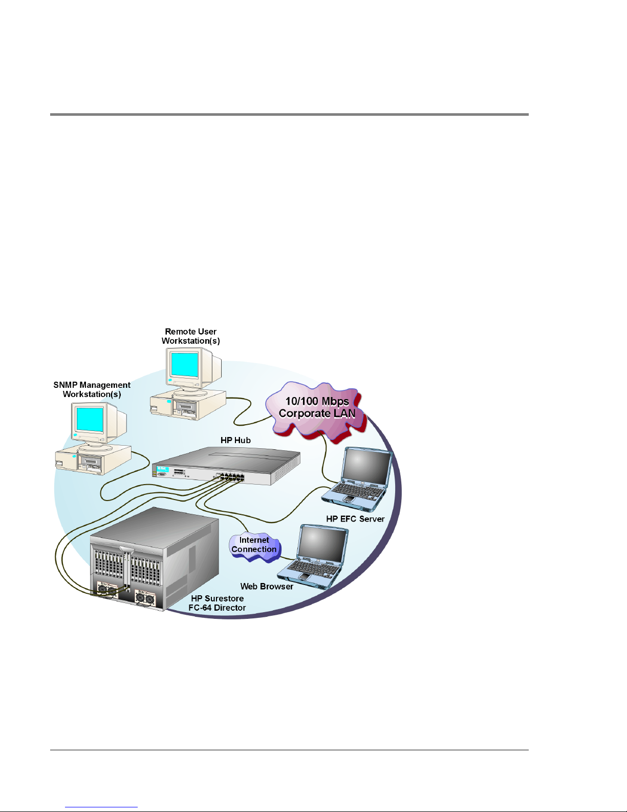
workstations, as shown in Figure 1, using any standard web browser. For instructions,
refer to the appendix in the hp enterprise fabric connectivity manager User’s Guide
(A6575-90901) that pertains to the operating system of your workstatio n.
Install the HP EFC Manager, Fabric Manager, and Product Manager applications on a
customer-supplied server platform, using instructions provided with the applications for
that platform.
Figure 1
8 EFC Management Menu Options
HP EFC Server and Remote Workstation Configuration (Dual Ethernet)
Page 25

Using the Product Manager, you can:
• Back up and restore c o nfiguration data.
• Clear the system error indicator.
• Configure extended distance buffering for po rts.
• Configure Fibre Channel operating parameters for the director.
• Configure individual ports with a port name describing the node attached to the port.
• Configure keys for new features.
• Configure Link Incident (LIN) alerts.
• Configure interoperability mode for multiswitch fabrics.
• Configure a nickname to display instead of the WWN for the director and for attached
node devices.
• Configure port binding.
• Configure SNMP trap recipients and community names.
• Configure the Open Systems Management Server feature, if installed.
Product Manager
Overview
• Configure the director name, lo cation, description, and contact person.
• Control individual Fibre Channel ports by blocking/unblocking operation and running
internal and external loopback diagnostics.
• Display FRU properties such as the FRU name, physical position in the directo r (chassis
slot number), active failed state, part number, and serial number.
• Display information for individual Fibre Channel ports, such as the port name, port
number, Fibre Channel address, operational state, type of port, and login data.
• Display information on nodes attached to ports.
• Display port performance and statistics.
• Display vital product data for the director, such as the system name, description,
contact person, location, status, model number, firmware and EC level, and
manufacturer.
EFC Management Menu Options 9
Page 26

• Enable beaco ning for po rts and the director unit.
• Monitor the operational status of the direc tor and each of its hardware field-replaceable
units.
• Perform an initial program load (IPL).
• Perform maintenance tasks for the director including maintaining firmware levels,
administering the call-home feature, accessing the director logs, and collecting data to
support failure analysis.
Call-home may not be available if you are using a customer-supplied server platform
for the EFC Management applications.
• Reset port operatio n.
• Run po rt diagnostics.
• Set the date and time on the director.
10 EFC Management Menu Options
Page 27

Using the Product Manager
This section provides a general overview of the Product Manager and its functions. For
details on performing specific tasks and using specific dialog boxes, refer to the
appropriate chapters in this guide.
Using Dialog Boxes
Buttons such as OK, Activate and Close or Cancel initiate functions in a dialog box. Click a
button to perfo rm its labeled function. Note the difference between the OK and Activate
butto ns. The OK button saves the data you entered and closes the dialog box. The Activate
button saves the data you entered without closing the dialog box. There is also a difference
between the Close and Cancel buttons. The Close button closes the dialog box and saves
the data you entered. The Cancel button cancels the operation and closes the dialog box
without saving the information you entered.
Keyboard Navigation
Keyboard navigatio n is an alternative to mouse navigation. The Product Manager and HP
EFC Manager support standard keyboard navigation.
Logging in to the HP EFC Manager
Product Manager
Overview
To open the Product Manager, you must first log in to the HP EFC Manager.
1. Perform one of the following steps:
– If you are using the HP EFC server, the HP EFC Manager application automatically
starts when you power on or reboot the EFC server. If you reboot the director or the
Using the Product Manager 11
Page 28

HP EFC server and the HP EFC Manager login screen displays, skip to step 3 to log
in.
– If you are using a remo te user wo rkstation, follo w steps 2 through 5.
– If the HP EFC Manager window is displayed, skip to Opening the Product Manager
on page 14.
2. Perform one of the following steps if you are using a remote user workstation (a
netwo rk PC with a remote client installed) , and the HP EFC Manager login screen or HP
EFC Manager window is not displayed. If the login screen is displayed, go to step 3.
– Start the HP EFC Manager and display the login screen by double-clicking the HP
EFC Manager icon on the desktop.
Figure 2
HP EFC Manager Icon
The HP EFC Manager login screen appears.
– If the HP EFC Manager window is open (Figure 3) and yo u need to log in as another
user or access a different HP EFC server, select Logout from the Logout or Logout/
Exit icon on the navigation control panel to display the login screen. Go to step 3.
3. When the HP EFC Manager login screen displays, enter yo ur user name and password.
The default user name is Administrator and password is password unless changed by
your system administrator.
Note The default user name for the right to view status and o ther information is
“operator.” The default user name for the right to modify c o nfiguration data,
perform maintenance tasks, or perform other options is “administrator.” The
default password for both user names is “password.”
12 Using the Product Manager
Page 29
Note If the HP EFC Manager window is open (Figure 3) and yo u need to log in as
another user or ac cess a different HP EFC server, select Lo go ut fro m the Logout
or Lo gout/Exit menu on the navigation control panel to display the login sc reen.
4. In the EFC server box on the login screen select the HP EFC server to which you wish
to co nnect. Note that if you are logging into an HP EFC server locally, localhost is the
HP EFC server name. Type in the network address of the server if it is not in the list.
5. Click Ac tivate or press the Enter key on your keyboard.
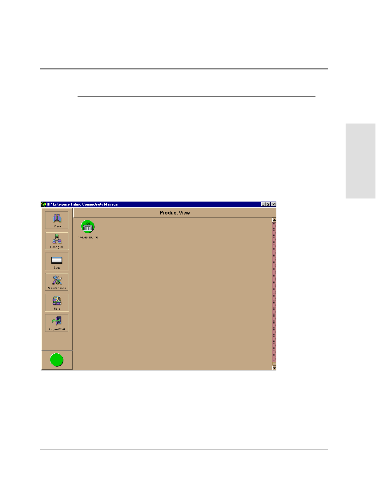
The main HP EFC Manager window displays showing the Product View.
Product Manager
Overview
Figure 3
Main HP EFC Manager Window
Using the Product Manager 13
Page 30

Opening the Product Manager
To open the Product Manager, click the product icon in the Product View or right click the
icon and select Open.
Figure 4
FC-64 Icon
The Produc t Manager displays showing the default Hardware View.
14 Using the Product Manager
Page 31
Title P
l
Navi
l
Alert
Panel
gation Control Pane
ane
Main Panel
Product Manager
Overview
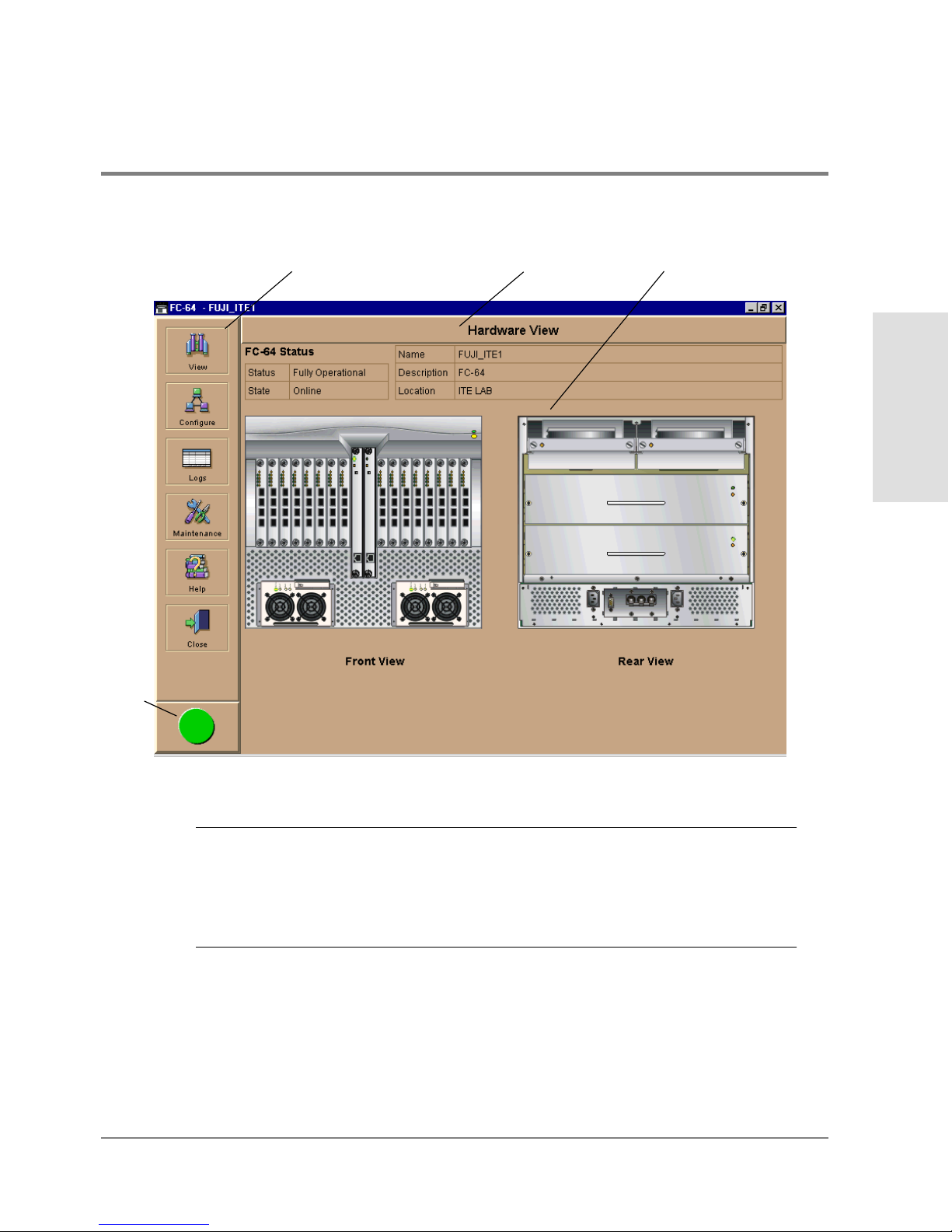
Figure 5 FC-64 Product Manager Window
Note The HP EFC Manager window is still available as a separate window. You can
drag the Produc t Manager windo w away from the HP EFC Manager window
and view both windows on your PC desktop or minimize one or both of them to
icons if desired. You can have a maximum of four Product Manager windows
open concurrently.
Using the Product Manager 15
Page 32

Window Layout and Function
The main Product Manager window is divided into four main panels as shown in Figure 5:
title panel, navigation control panel, alert panel, and main panel. Use features in these
panels to configure director operation, monitor performance, and access maintenance
features.
Title Panel
The title bar identifies the current view. In Figure 5, Hardware View displays in the title
panel. Other possible views include Port List View, FRU List View, Node List View, and
Performance View.
Navigation Control Panel
The navigation control panel is the vertical panel on the left side of the window. Move the
cursor over each of the six icons in this panel to display pop-up menu options that allow
you to perform tasks related to the director. You can select optio ns to c hange views o n the
main panel, perform configuration tasks, and access director performance data,
maintenance tools, and online help. The following sections describe Product Manager
icons and pop-up menus.
Vi e w
Place the cursor over the View icon to display a menu that lists the five following views in
the main panel.
• Hardware
The Hardware View is the Product Manager default view.
The Hardware View is a dynamic illustration of all hardware components installed in
the front and bac k of the director. Operational status o f the director and hardware
components is indicated by simulated light emitting diodes (LEDs) and colored alert
16 Using the Product Manager
Page 33

symbols displayed in the graphics. Refer to Figure 6 for an example of the Hardware
Vi ew.
For additio nal information on this view, refer to Hardware View on page 50.
• Port List
The Port List View is a table of data on all Fibre Channel ports in the director. This data
includes the port number, port name, blocked configuration state, operational state
(such as online or failed), type of port (G_Port, F_Port, or E_Port), and any link
incident alerts.
For additional information on this view, refer to Port List View on page 78.
• FRU List
The FRU List View is a table of detailed information on all FRUs installed in the
director. (A FRU is a hardware component that can be replaced as an assembly if it
fails.) Information includes the FRU name, slot position in the chassis relative to
identical FRUs in the director, operational status (active or failed), part number, and
serial number.
For additional information on this view, refer to FRU List View on page 82.
• Node List
The Node List View is a table of information about the node attachments to existing
F_Ports, sorted by port number. Informatio n inc ludes the directo r’s port number, no de
type, port world wide name, and the buffer-to-buffer credit (BB_Credit) allocated to
the port. To find out more about the attached node, display the Node Properties dialog
box by right clicking on a port’s row and selecting Node Properties from the pop-up
menu.
Product Manager
Overview
For additional information on this view, refer to Node List View on page 84.
Using the Product Manager 17
Page 34

• Perf ormance
The Performance View contains a bar graph for each of the director ports. Each graph
shows the current throughput percentage for each port and marks the highest
throughput achieved. By clic king a bar graph for a port, yo u c an display cumulative
port statistics and error count values for the port, including traffic statistics, class 2
and 3 accounting statistics, and error statistics.
For additio nal information on this view, refer to Performance View on page 90.
Configure
Place the cursor over the Configure icon to display a menu that lists the following options.
For detailed information on using these options, refer to Chapter 3.
• Identification
Select this optio n to display the Configure Identification dialog box. Enter the
following info rmation in this dialog box:
– Name - Assign a product name. Note that you can set this name as the nickname fo r
the director’s WWN, using the Set Name as Nickname chec kbo x. The nickname then
displays instead of the WWN in Product Manager views.
– Description - Assign a unique product description.
– Location - Desc ribe the product’s location.
– Contact - Assign a contact either by name, phone number, or e-mail address.
Note This information displays in the identification table at the top of the Hardware
View and in the HP EFC Manager Product View, if the Produc t View is
configured to display names.
18 Using the Product Manager
Page 35

• Operating Mode
The director must be offline before you change operating modes.
Select this option to displays the Configure Operating Mo de dialog box. Use this dialog
bo x to configure the appropriate interoperability mode to work with the multiswitch
fabric. Refer to Configure Operating Mode on page 107 for instructions.
• Operating Parameters
Select this option to display the Configure Operating Parameters dialog box for setting
Fibre Channel operating parameters. In this dialog bo x, yo u c an set buffer-to -buffer
credit (BB_Credit) from 1 to 60. You can also set the reso urce allocation-time-out value
(R_A_TOV) and error-detect-time-out value (E_D_TOV) in tenth-of-a-second
increments. In addition, you can configure fabric operating parameters, such as
preferred domain ID from 1 to 31 and director priority level as principal, default, or
never principal. Refer to Configure Operating Parameters on page 110 for more
information o n configuring these parameters for the direc tor.
• Port s
Select this option to display the Configure Ports dialog box.
Product Manager
Overview
For each port you c an provide a name, block o r unblock o peration, configure extended
distance buffering for 10 to 100km, enable LIN alerts for each port, define a type (G, F,
and E) , and enable port binding.
Note Ports are automatically configured as G_Ports if no device is connected,
F_Ports if a device is connected, and E_Ports if a director is connected.
• Management Server
Select this option to display the Configure Open Systems Management Server dialog
box, depending on which feature (if any) is enabled for the direc tor. Use this to
configure an open systems inband management program to function with the director.
To use these procedures, you must have enabled the Open Systems Management
Server through the Configure Feature Key dialog bo x.
Using the Product Manager 19
Page 36

• SNMP Agent
Select this option to display the Configure SNMP dialog box. Use this dialog box to
configure network addresses and community names for up to six SNMP trap
recipients. Also authorize write permissions to enable SNMP management stations to
modify writable MIB variables. In addition, you can enable authorization traps to be
sent to management stations when unautho rized stations request access to director
SNMP data.
• Features
Displays the Configure Feature Key dialog box. Use this dialog box to enter a feature
key to enable optional features that you have purchased for the director.
• Date/Time
Select this option to display the Configure Date and Time dialog bo x. Use this option to
set the current date and time in the director. When the Periodic Date/Time
Synchronization check box is checked, the Date and Time fields are greyed out
(disabled), and the HP EFC server date and time periodically synchronizes the director
date and time. If the Periodic Date/Time Synchronization check box is not checked,
you can set the date and time in the dialog box fields manually.
• Threshold Alert(s)
Select this optio n to configure threshold alerts for ports. A threshold alert notifies
users when the transmit (Tx) or rec eive (Rx) throughput reaches specified values for
specific director ports or port types (E_Ports or F_Ports). Using this option, you can
configure:
– A name for the alert.
– A threshold type for the alert (Rx, Tx, or either).
– Active or inactive state of the alert.
Threshold criteria. This includes configuring the threshold as the percent of port traffic
capacity utilized (% utilization), the time interval for measuring throughput and
sending notification, and the amount of cumulative minutes that the % utilization
should exist before an alert is generated.
20 Using the Product Manager
Page 37

• Export Configuration Report
Select this option to display the Export Configuration Report dialog box, which
enables you to specify a file name in which to save an ASCII text file containing all
current user-definable configuration options in a printable format. Note that this file
cannot be read bac k into the Produc t Manager in order to set configuration
parameters.
r Enable Web Server
Select this option place a check mark in the check box to enable the Embedded Web
Server Interface o n the director. Select the optio n again to remove the chec k mark and
disable the Embedded Web Server Interface. When disabled, users at remote
wo rkstations cannot access the interface.
• Enable Telnet
Select this option place a check mark in the c heck box to enable telnet access to the
director. Select the o ption again to remove the chec k mark and disable telnet access.
When disabled, users at remote workstations c annot access the direc to r through telnet
to use the Command Line Interface (CLI) or perform other tasks.
Logs
Product Manager
Overview
Place the cursor over the Logs icon to display a menu that lists the following options. For
detailed information on using these dialog boxes, refer to Using Logs on page 148.
• Audit Log
This log provides a record of all configuration changes made on the director. Each
entry displays the date and time of the change, a description of the change, the source
of the change (such as the HP EFC server o r SNMP management station), and an
identifier for the source, such as the IP address of the HP EFC server or SNMP
management station.
Using the Product Manager 21
Page 38

• Event Log
Select this option to display the director event log. This log provides a record of
significant events that have occurred on the director, such as hardware failures,
degraded operation, and port problems. Each entry includes the date and time of the
event, a reason code for the event, the severity level, a brief description, and up to 32
bytes of supplementary event data. Refer to the hp surestore director fc-64
Installation and Service Manual (HP 6534--90902) for more information.
• Hardware Log
This log displays information on FRUs inserted and removed from the direc tor. Each
log entry includes the name of the FRU inserted or removed, the slot position relative
to identical FRUs installed, whether the FRU was inserted or removed, the FRU part
number and serial number, and the date and time the FRU was inserted or remo ved.
• Link Incident Log
The link incident (LIN) lo g displays the most recent incidents with their date and time,
port number, and description of the incident. A link incident can be one of several
conditions detected on a fiber optic link. For a list of events that may cause a link
incident to be written to the log, refer to Link Incident Log on page 158.
• Threshold Alert Log
This lo g provides notifications of threshold alerts. Besides the date and time that the
alert occurred, it also displays information that was configured through the Configure
Threshold Alert(s) option under the Configure menu. This includes the alert name, port
fo r which the alert is configured. the type of alert (transmit throughput, receive
throughput, o r both), threshold utilization o f traffic capacity, minutes the threshold
was configured for, and the configured time interval for the thresho ld. For more details
on this log, refer to Threshold Alert Log on page 160.
22 Using the Product Manager
Page 39

Maintenance
Product Manager
Place the curso r o ver the Maintenance icon to display a pop-up menu that lists the
following options. For detailed information on using these dialog boxes, refer to Chapter 5.
• Port Diagnostics
This option displays the Port Diagnostics dialog box. Use this dialog box to run internal
and external loopback tests on ports. Refer to the hp surestore director fc-64
Installation and Service Manual (HP A6534-90902) for instructions.
• Data Collection
This option displays the Save Data Collection dialog box. Use this dialog box to collect
maintenance data into a file. This file is used by support perso nnel to diagnose system
pro blems. Refer to the hp surestore director fc-64 Installation and Service Manual
(HP A6534-90902) for instructions.
• IPL
Select this option to initiate an initial program load on the director. A dialog box
displays to allow you to confirm the IPL. Note that an IPL does not affect any
configuration settings done through the Product Manager. Po rt operation is interrupted
during the IPL.
Overview
Refer to the hp surestore director fc-64 Planning Guide (HP A6534-90903) for more
information.
• Set Online State
Select this option to display the Set Online State dialog box. Use this dialog box to
change the online state of the director to offline or online.
• Firmware Library
Select this option to display the Firmware Library dialog box. This dialog box displays
all firmware versions c urrently installed on the HP EFC server that can be downloaded
Using the Product Manager 23
Page 40

to directors. Use this dialog box to add a new firmware version to the HP EFC server
hard disk, modify the description displayed for an existing version, delete a version
from the PC, or download (send) a version for operation on a director. For additional
information on using this option, refer to the hp surestore director fc-64 Installation
and Service Manual ( HP A6534-90902).
• Enable E-Mail Notification
The Simple Mail Transfer Protocol (SMTP) server and e-mail recipient addresses are
configured in the HP EFC Manager application (not in the director’s Product Manager).
E-mail notification is also initially enabled in the HP EFC Manager for all directors
managed by the HP EFC Manager. Note, however, that the E-Mail Notification option
on the Product Manager’s Maintenance menu must be enabled (checked) for e-mail
notification to oc cur for the specific director.
The default setting for the Enable E-Mail Notific ation function is enabled ( checked). To
disable the function, select Enable E-Mail Notification from the Maintenance menu to
clear the check box.
For additional information on using this option, refer to Enable E-Mail Notification on
page 171.
• Enable Call Home Notification
The default setting for the Enable Call Home Notific ation function is disabled
(unchecked).
Select Enable Call Home Notification from the Maintenance icon’s pop-up menu to
enable the call-home function for the director.
The parameters of the call-home feature are configured in Windows 2000. Refer to the
hp surestore director fc-64 Installation and Service Manual (HP A6534-90902) for
instructions.
The call-home feature may not be available if you are using a customer-supplied server
platform for the EFC Management applications.
24 Using the Product Manager
Page 41

• Backup & Restore Configuration
Select this option to save the product configuration stored on the director to the HP
EFC server hard disk or to restore the configuration data from the HP EFC server. Only
a single copy of the configuration is kept on the server.
This backup is primarily for single-CTP systems, where a backup is needed to restore
the c onfiguration data to a replacement CTP card. Yo u cannot modify the location or
the file name of the saved configuration.
For additional information on using this option, refer to Backup and Restore
Configuration on page 173.
You can only restore the configuration to a director with the same IP address.
• Reset Co nfigurat ion
Select this optio n to reset all direc tor configuration data back to the factory defaults. A
confirmation dialog box displays with a warning upon selecting the option. For
additional information on using this option, refer to Reset Configuration on page 175.
CAUTION This operation resets all configuration including any optional features that
have been installed. You will need to re-enter your feature key to enable all
optional features after resetting the configuration.
Product Manager
Overview
Help
Place the cursor over the Help icon to display a menu that lists the following options.
• Contents
Select this option to display the Help window. The Help window contains Contents,
Index, and Glossary buttons and hypertext-- linked items to help you quickly navigate
through information. Use the forward (>) and back (<) buttons to scroll forward and
Using the Product Manager 25
Page 42

backward through the displayed help frames. Exit the help feature at any time by
clicking the Clo se icon at the top of the Help window.
• About
Select this optio n to display the version number for the Product Manager and copyright
information.
Close
Place the cursor over the Close icon to display a menu that displays the Close option.
Select this optio n to close the Product Manager window and return to the HP EFC
Manage r.
Alert Panel
This panel, located below the navigation control panel, displays an alert symbol that
indicates the current state of the direc to r. Refer to Table 1 for the meaning of these alert
symbols and o f the corresponding alert text that displays in the FC-64 Status table at the
top of the Hardware View in the main panel.
If a gray square displays in the alert panel (no Ethernet co nnection), a reason for the status
displays in the Status table at the top of the Hardware View. Refer to No Link Status on
page 51 for details.
Table 1
Symbol
26 Using the Product Manager
Operating Status - Alert Panel and Directo r Status
Alert
Panel
Green
Circle
Operator
Panel Text
Online or
Offline
Director Status Table
Text Meaning
Fully Operational All components and installed ports
are operational; no failures.
Page 43
Table 1 Operating Status - Alert Panel and Directo r Status
Symbol
Alert
Panel
Yellow
Triangle
Red
Diamond
with Yellow
Backgroun
d
Gray
Square
Operator
Panel Text
Director Status Table
Text Meaning
Degraded Redundant Failure A redundant component has failed,
such as a power supply, and the
backup component has taken over
operation.
Minor Failure A failure occurred which has
decreased the director operational
ability. Normal switching opera tions
are not affected.
One or more FPM cards failed, but
at least one FPM card is still
operational.
A fan has failed or is not rotating
sufficiently.
One of two CTP cards failed.
One of two SBAR cards failed.
Failed NOT OPERATIONAL A critical failure prevents the
director from performing
fundamental switching operations.
- All fans fail.
- Both SBAR cards fail.
- All installed FPM cards fail.
N/A Never Connected
Link Timeout
Protocol Mismatch
Duplicate Session
Unknown Network
Address
Incorrect Product Type
Director status is unknown. This
occurs if the Ethernet network
connection between the HP EFC
Server and the director cannot be
established or if the CTP fails.
Refer to No Link Status on page
105 for details on the status table
text.
Product Manager
Overview
Using the Product Manager 27
Page 44

Main Panel
The main panel displays the Hardware View, Port List View, FRU List View, Node List View,
and Performance View. Place the cursor over the View icon and select one of the options
from the pop-up menu. For detailed information on using these views, refer to Chapter 2.
Hardware View
The Hardware View is the default view that displays in the main panel when you open the
director Product Manager. Refer to Figure 6 for an example of this view.
Figure 6
28 Using the Product Manager
Hardware View
Page 45

In the Hardware View, colored indicato rs reflect the status of ac tual LEDs on the director
FRUs. The alert panel displays a symbol to represent the most degraded status currently
reported by any of the director FRUs. For example, for a port failure, indicated by a
blinking red and yellow diamond on a port, a yellow triangle displays on the alert panel to
indicate a degraded condition. However, if a blinking red and yellow diamond displays over
both SBAR cards, the alert panel displays a blinking red and yellow diamond, which
indicates a failure requiring immediate attention. For an explanation of the different alert
symbols and the reasons they display in the Hardware View or Port List View, refer to
Monitoring Hardware Operation on page 53.
Click on the power supply, CTP card, cooling fan module, and SBAR card to display a FRU
Properties dialog box containing detailed information on the hardware component. Click
on the director, away from a FRU, to display the Director Properties dialog box.
For details on navigating and mo nitoring via the Hardware View, refer to Chapter 2.
Director Menu. Click on the graphic away from a FRU to display the Director Properties
dialo g box. Right click on a hardware graphic away from a FRU to display the fo llowing
options:
• Director Properties
• Enable Unit Beaconing
Product Manager
Overview
• Clear System Error Light
• IPL Director
• Set Director Date and Time
• Set Director Online State
For details on menu options, refer to Director Menu on page 59.
For details on navigating and mo nitoring via the Hardware View, refer to Chapter 2.
FPM Card Menu. Click on an FPM card to display the Port Card View. See Using the Port
Card View on page 66. Right click on the FPM card to display the following options:
• Open Port Card View
• FRU Properties
Using the Product Manager 29
Page 46

• Enable Beaconing
• Block All Ports
• Unblock All Po rts
• Diagno stics
CTP Card Menu. Click on a CTP card to display the Properties dialog box for the card.
Right clic k on a CTP card to display the following options. For details refer to Using the
Port Card View on page 66.
• FRU Properties
• Enable Beaconing
• Switc hover
Cooling Fan Module. Click on a Fan Module on the Rear View to display the FRU
Properties dialog box for the module. For details refer to Fan Module on page 65.
SBAR Card Menu. Click on an SBAR card to display the FRU Properties dialog box for
the c ard. Right click on a SBAR card to display the following optio ns: For details refer to
SBAR Card Menu on page 65.
• FRU Properties
• Enable Beaconing
• Switc hover
Port Card View
Click on an FPM card in the Hardware View or right click on an FPM card and select Port
Card View from the pop-up menu to display the Port Card View for that port (Figure 7).
30 Using the Product Manager
Page 47

Figure 7 Port Card View
Product Manager
Overview
In this expanded view of the port card, you can:
• Determine FPM card status by amber LED at the top of the card. A table also displays
on the Port Card View that provides the FRU name, position, operating state, beaconing
state, and part number.
• Determine port status and operation by the alert symbols that display next to the port
connectors and simulated LED indicators above the connectors.
• Right-click on the port card to display a pop-up menu with Block All Ports, Unblock All
Ports, and Diagnostics options.
Using the Product Manager 31
Page 48

• Right-clic k the port co nnector to display a menu with Po rt Properties, Node Properties,
Port Technology, Block Port, Enable Beaconing, Diagnostics, Clear Link Incident
Alert(s), Reset Port, WWN Binding, and Clear Threshold Alert(s) options.
• Click on a port connector to display the Port Properties dialog box.
• Return the Hardware View by clicking Back to Full View.
• Refer to Using the Port Card View on page 66 for detailed information on this view.
Port List View
Select the Port List View from the View menu. A table listing the port number, port name,
the block/unblo ck configuration, operating state, port type, and alert condition displays in
the main panel. Figure 8 shows an example of the Port List View.
32 Using the Product Manager
Page 49
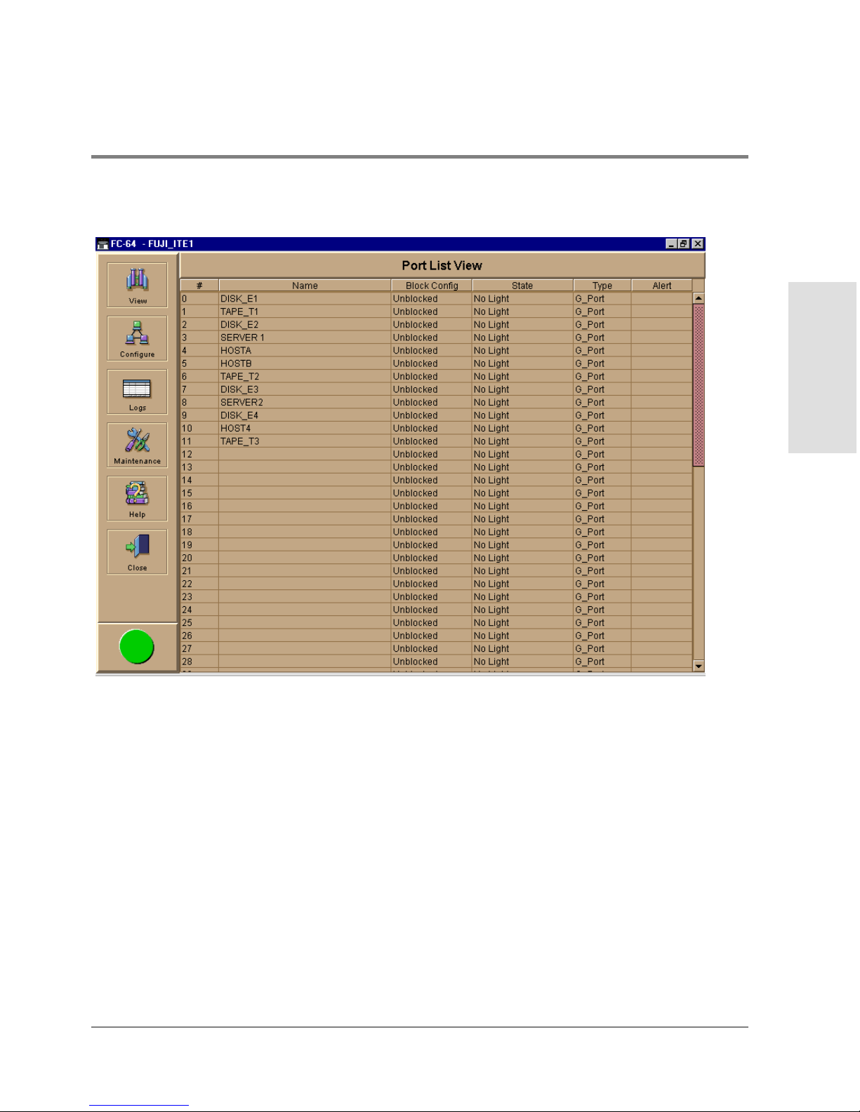
Figure 8 Port List View
Product Manager
Overview
The Port List View displays information about all ports installed in the direc tor. All data is
dynamic and updates automatically. Click on any row in this view to display the Port
Properties dialog box for the port.
Right click on a port row to display the same menu options that display when you right
clic k a port in the Port Card View o r a port’s bar graph in the Performance View. These
include:
• Port Properties
• Node Pro perties
Using the Product Manager 33
Page 50

• Port Tec hno logy
• Block Po rt
• Enable Beaconing
• Diagno stics
• Clear Link Incident Alert(s)
• Reset Port
• WWN Binding
• Clear Threshold Alert(s)
For details on these menu options, refer to Port Menu on page 63.
For details on navigating and monitoring using the Port List View, refer to Port List View on
page 78.
FRU List View
Select FRU List from the View menu. A table with information about each of the FRUs
installed in the director displays in the main panel. All data is dynamic and updates
automatically. Figure 9 shows an example of the FRU List View.
34 Using the Product Manager
Page 51

Figure 9 FRU List View
Product Manager
Overview
For details on navigating and monitoring via the FRU List View, refer to FRU List View o n
page 82.
Node List View
Select Node List from the View menu. Figure 10 shows an example of the Node List View.
This view displays a table with information about all node attachments or N_Ports that
have logged in to existing F_Ports on the director. Only N_Ports display in the Node List
View after nodes have logged in to the fabric. The c olumns that display in the table include:
port number where the node is attached, node type, WWN of the attached node (device),
and BB_Credit used by the attached node.
Using the Product Manager 35
Page 52
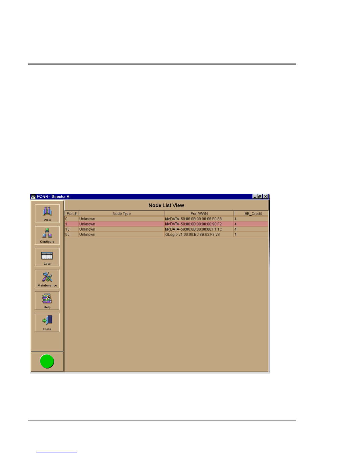
Click on a port ro w to highlight it and display the Node Properties dialog box for that port.
Right clic k on a port row to display the following menu options:
• Node Properties: Displays the Node Properties dialog box.
• Port Properties: Displays the Port Properties dialog box.
• Define Nickname: Displays the Define Nickname dialog box, where you can define a
nickname to display for the attached device instead of the device’s eight-byte WWN.
• Display options: Allows you to display attached devices listed under the Port WWN
column in the Node List View by the device’s nickname configured through the Define
Nickname menu option or the device’s WWN.
Figure 10
36 Using the Product Manager
No de List View
Page 53

For details on navigating and monitoring via the Node List View, refer to Node List View on
page 84.
Performance View
Select Performance from the View menu. Figure 11 shows an example of the Performance
View. This view provides a graphical display of performance for all ports. The top portion
of the Performance View displays bar graphs that show the level of transmit/receive
activity for each port. This information updates every five seconds. Each bar graph also
shows the percentage link utilization for the port. A red arrow marks the highest utilization
level reached since the Performance View was opened. If the system detects activity on a
port, it represents minimal activity with at least o ne bar.
When an end device (node) is logged in to a port, moving the cursor over the port’s bar
graph in the Performance View highlights the graph and displays a message with the WWN
of the connected node. If the connected node has more than one port, this is the WWN of
the specific port on the node. When a port is functioning as an expansion port (E_Port), the
message is “E_Port.” When a port is not logged into an end-device (not functioning as an
F_Port) or to another director (not functioning as an E_Port), the message is the port’s
current online state.
Product Manager
Overview
Using the Product Manager 37
Page 54

Figure 11 Performance View
Right clic k a bar graph to display a menu of port-related actions. The options available on
this menu are the same as those that are available when you right-click a port in the Port
Card View or right click a row in the Port List View. These include:
• Port Properties
• Node Pro perties
• Port Tec hno logy
• Block Po rt
• Enable Beaconing
38 Using the Product Manager
Page 55

• Diagno stics
• Clear Link Incident Alert(s)
• Reset Port
• WWN Binding
• Clear Threshold Alert(s)
For details on port menu optio ns, refer to Port Menu on page 63.
The bottom portion of the Performance View displays cumulative statistical information
fo r the port selected in the bar graph. Click Refresh to update the data with current data
from the port.
Click Clear to clear all of the counters to zero for the selected port and to place an entry in
the audit log indic ating that statistics for the port have been cleared.
Clearing the counters clears the statistics for all users.
For more information about the Perfo rmance View, including statistics descriptions, refer
to Performance View on page 49.
Product Manager
Overview
Closing the Product Manager
To close the Product Manager, use the following steps:
1. Selec t Close from the Close menu to clo se the Product Manager window.
2. Select Logout or Exit from the Logout/Exit menu on the HP EFC Manager’s Product
View w indo w.
– If you select Logout, the HP EFC Manager Login dialog box displays. You can now
log in again using a user name and password. Log into a different HP EFC server by
selecting a different server from the EFC Server box.
– If you select Exit, the Product View window c loses.
Using the Product Manager 39
Page 56

User Rights
The HP EFC Manager’s system administrator can assign levels of access, or “User Rights,”
to Produc t Manager users through the HP EFC Manager application.
Note that the HP EFC Manager’s system administrator only has view rights while operating
in a specific Product Manager application. Conversely, a Product Manager’s product
administrator only has view rights while operating in the HP EFC Manager application.
Detailed instruc tions concerning the assignment of user rights for both the HP EFC
Manager and Product Manager applications appear in Chapter 5 of the hp enterprise fabric
connectivty manager User’s Guide (HP A6575-90901).
There are five levels of access or “user rights” that can be assigned to specific users:
• System Administrator
• Produc t Administrator
• Operator
• Maintenanc e
• Vi ew
By default, all users have view rights, which allow viewing but not changing configurations.
View rights canno t be removed.
The users with system administrator rights can make all control and configuration changes
implemented through the HP EFC Manager application.
User Rights for Specific Functions
Table 2 itemizes the specific functions available to Produc t Manager users that have been
assigned “user rights” of product administrator, operator, and/or maintenance. If a user
does not have the right to perform a specific operation, a not-authorized erro r box appears
when the operation is attempted.
40 Using the Product Manager
Page 57

Table 2 User Rights for the Product Manager
Product
Product Manager Rights
Backup and Restore
Configuration
Clear Audit Log X
Clear Event Log X
Clear Hardware Log X X
Clear LIN Alert X X X
Clear LIN Log X
Clear System Error Light X
Clear Threshold Alerts X
Clear Threshold Event Log X
Configure Date/Time X X X
Configure Feature Key X
Configure Identification X
Configure Management Server X
Configure Operating Mode X
Configur e Operating Parame ters X
Configure Port Binding X X
Configure Ports X X
Configure SNMP X
Configure Threshold Alerts X
Configure Zoning X
Data Collection X
Date/Time Sync Configuration X X X
Enable Call Home Notification X
Enable E-Mail Notification X
Enable Telnet X
Enable Web Server X
Administrator Operator Maintenance
XXX
Product Manager
Overview
Using the Product Manager 41
Page 58

Table 2 User Rights for the Pro duct Manager ( cont’d)
Product
Product Manager Rights
Export Configuration Report X X X
FRU Beaconing X
FRU Switchover X
IPL X X X
Manage Firmware X
Port Diagnostics X
Port Beaconing X X X
Set Online S t ate X X X
Reset Configuration X
Reset Statistics Counters
(Performance View)
Reset Port X X
Unit Beaconing X X X
View Event Log X
View Firmware X
View Hardware Log X X
View LIN Log X X X
View SNMP X X
View Threshold Alert Log X X X
Administrator Operator Maintenance
XX
42 Using the Product Manager
Page 59

Backing Up and Restoring Product Manager Data
As long as a Zip disk remains in the Zip drive of the HP EFC server, critical information
fro m both the Product Manager and HP EFC Manager applications automatically backs up
to the Zip disk when the data directory contents change or when you reboot the HP EFC
server.
The application used for this function is Iomega QuikSync, a separate applic ation installed
on the HP EFC server. QuikSync is c o nfigured to automatically mirror the contents of the
EfcData directory to the Zip drive when the contents are changed or when you reboot the
HP EFC server. This directory c o ntains all HP EFC Manager and Product Manager data, so
it can be copied back to a newly restored HP EFC server to fully recover the preferred
operating environment.
The QuikSync application and a Zip drive may not be available if you are using a customersupplied (non-HP supported) server platform for the EFC Management applications.
The mirroring operation will only occur while a user is logged in to Windows 2000 on the
HP EFC server PC (independent of the HP EFC Manager login).
The data co ntained in the EfcData directory and mirrored to the Zip disk includes the
following:
• All HP EFC Manager configuration including:
Product Manager
Overview
– Produc t definitio ns
– User names, encrypted passwords, and user rights
– Nic knames
– Session options
– HP EFC Manager SNMP configurations
– E-mail configuration
• All log files (both HP EFC Manager log files and individual Product Manager log files).
Backing Up and Restoring Product Manager Data 43
Page 60

• Zoning library (all zone sets and zo ne definitions).
• Firmware library.
• Call-home c onfiguration (including phone numbers and dialing options).
• Configuration data saved to the EfcData directory through the Backup & Restore
Configuration option on the Pro duc t Manager Maintenanc e icon po p-up menu.
The QuikSync application will not backup certain Windows 2000 configurations that need
to be rec onfigured on a newly restored HP EFC server, including the following:
• Windows 2000 user names and passwords.
• TCP/IP netwo rk configuration (such as IP address, gateway address, and DNS names).
The QuikSync application will be included on the EFC Management Applications CD. It
automatically installs on the HP EFC server during the EFC server install process. A blank
Zip disk is required for each HP EFC server and is included with the EFC server
deliverables.
Restoring Data to the HP EFC Server
To restore data to the HP EFC server, copy the: EfcData directory from the zip disk to:
C:\(root directory on the C drive)
Using QuikSync
QuikSync is functioning to back up data when the QuikSync icon displays in the system
tray in the right corner of the Windo ws 2000 task bar (Figure 12). This ic on spins when data
is writing to the Zip disk.
Figure 12
If an icon does not display, you must enable the application using the procedure o utlined in
Enabling QuikSync on page 45.
QuikSync Ico n in Windows System Tray
44 Backing Up and Restoring Product Manager Data
Page 61
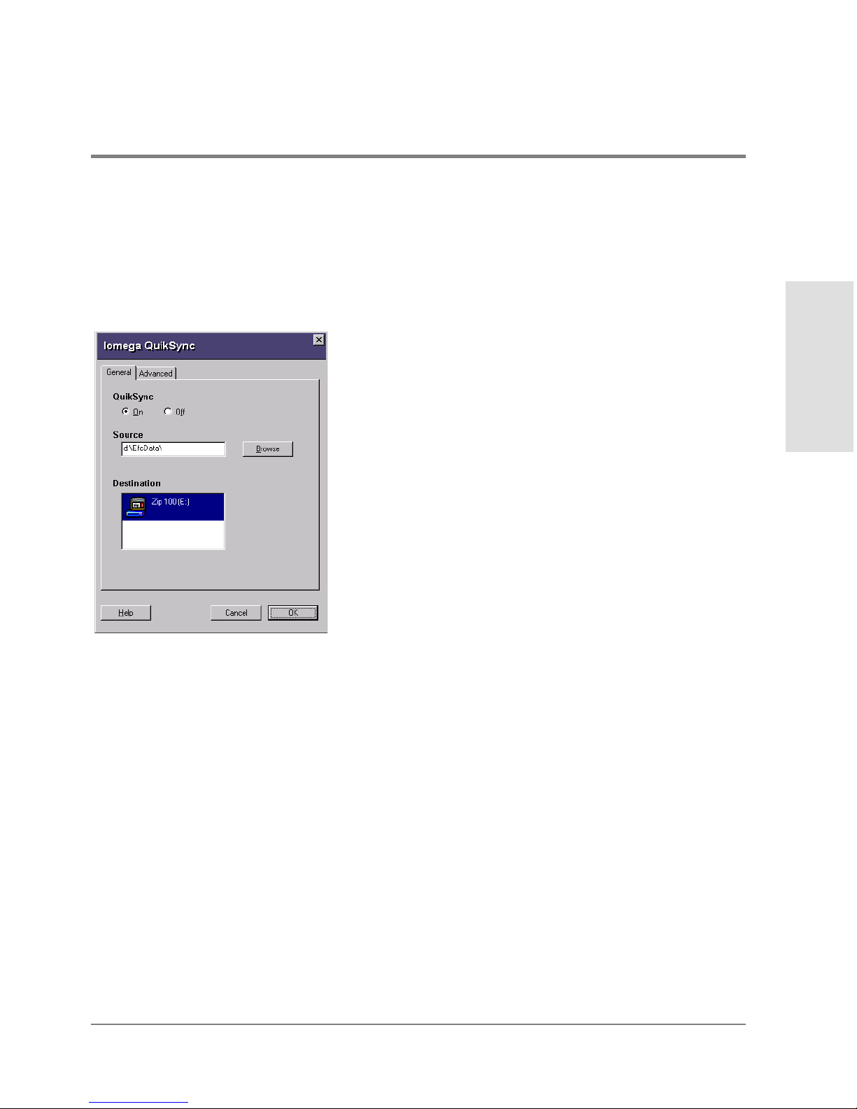
Enabling QuikSync
1. Click the Windows Start button and select Programs, then Iomega QuikSync and choose
QuikSync .
The Iomega QuikSync dialog box displays.
Figure 13
Iomega QuikSync Dialog Box
1. Click On to enable QuikSync
Product Manager
Overview
2. Click OK.
QuikSync Settings
Do not change the default settings for automatic backup of the EfcData directory. If you
feel that QuikSync is not functioning properly, check the settings using the following steps:
Backing Up and Restoring Product Manager Data 45
Page 62
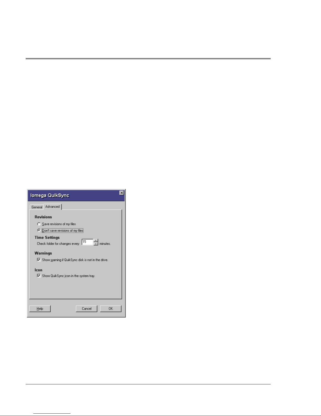
1. Open the QuikSync dialog box using one of these steps.
– Click the Windows Start butto n and select Programs, then Iomega QuikSync and
choose QuikSync.
– Double-click the QuikSync icon on the Windows system bar in the lo wer right co rner
of the Windows 2000 desktop.
– Right-click on the QuikSync icon and select Settings from the pop-up menu.
2. Verify that the dialog box is configured exactly as it displays in <X-Ref>Figure 13.
The d:\EfcData\ directory is a mirrored directory of c:\EfcData\. Do not change this
location in the So u rc e field.
3. Click the Advanced tab. The following displays:
Figure 14
Iomega QuikSync Dialog Box (Advanced Tab)
4. Verify that the dialog box is configured exactly as it displays in Figure 14.
r Clic k OK.
46 Backing Up and Restoring Product Manager Data
Page 63

QuikSync Settings
Do not change the default settings for automatic backup of the EfcData directory. If you
feel that QuikSync is not functioning properly, check the settings using the following steps:
1. Open the QuikSync dialog box using one of these steps.
– Clic k the Windows Start button and select Programs, then Iomega QuikSync->
QuikSync.
– Double-click the QuikSync icon on the Windows system bar in the lo wer right co rner
of the Windows 2000 desktop.
– Right-click on the QuikSync icon and select Settings from the pop-up menu.
2. Verify that the dialog box is configured exactly as it displays in Figure 13.
Note The d:\EfcData\ directory is a mirrored directory of c:\EfcData\. Do not change
this location in the Source field.
3. Click the Advanced tab. The following displays:
Product Manager
Overview
Figure 15
Iomega QuikSync Dialog Box (Advanced Tab)
Backing Up and Restoring Product Manager Data 47
Page 64

4. Verify that the dialog box is configured exactly as it displays in Figure 14.
5. Click OK.
48 Backing Up and Restoring Product Manager Data
Page 65

2 MONITORING AND MANAGING THE DIRECTOR
Hardware View
Port List View
FRU List View
Node List View
Performance View
Port Operational States
Link Incident Alerts
Managing the Director
Monitoring and
Threshold Alerts
49
Page 66

Hardware View
The Hardware View is the default view that is shown when you open the Product Manager.
If another view displays, you can display the Hardware View by selecting Hardware from
the View menu on the navigatio n control panel. Using this graphical view o f the director,
you can view alert symbols and simulated light emitting diode (LED) indicators, display
data, and use mouse func tions to monitor status and o btain vital product info rmatio n for
the director and its hardware components.
Identifying FRUs
Move the curso r o ver parts of the directo r graphic in the Hardware View to display labels
identifying each hardware component and its slot position in the chassis relative to
identical components installed in the director. Components include:
• Fiber po rt module (FPM) c ards. The director can c ontain up to 16 FPM cards, slot
positions 15 through 0 (left to right). As you move the cursor over each card, labels
appear, identifying the card’s slot number and port technology. Acronyms that may
display to identify port technology, such as GSML, GXXL, GSF1, GSF2, GLSR, GSMR,
GLSL, and GXXR, also display in the FRU column of the FRU List View. Refer to FRU
List View on page 82 for details.
• Control processor (CTP) cards. Two CTP cards are installed, slot positions 1 and 0 (left
to right).
• Power supply modules. Two modules are installed, slot positions 1 and 0 (left to right).
• Cooling fan modules. Two modules are installed, slot positions 1 and 0 (left to right).
• Serial Crossbars (SBAR). Two SBARs are installed, slot positions 1 (bottom) and 0 (top).
Monitoring Director Operation
Monitor the operating status of the director using the FC-64 Status table on the Hardware
View and the status indicator on the alert panel.
50 Hardware View
Page 67

Status Table
The Status table at the top of the Hardware View displays the director’s operational status,
operational state, name, description, and location.
Status. Refer to Table 1 for the meaning o f the text that displays in the director Status
table and the co rrespo nding alert symbols that display on the alert panel.
State. The State field displays one of the following:
• Offline
When the director is “OFFLINE,” all ports are offline. The ports cannot accept a login
from an attached device or cannot connect to other directors. You can configure this
state through the Set Online State dialog box. Refer to Set Director Online State o n
page 62 for instructions.
• Online
All unblocked ports are able to connect with devic es. You can configure this state
through the Set Online State dialog box. Refer to Set Online State o n page 163 fo r
instructio ns. Note that the director automatic ally goes online after a power-up, an
initial machine load (IML), or an initial program load (IPL).
Managing the Director
Monitoring and
• Coming online
This is a transitional state that occurs just before the director goes online. This state
normally only happens briefly, unless there is a problem reac hing the online state.
• Going offline
This is a transitional state that occurs just before the director goes offline. This state
normally only happens briefly, unless there is a problem reac hing the offline state.
No Link Status
If the Ethernet network connection between the HP EFC server and the director is down,
the Hardware View displays the front and rear of the unit without FRUs. The HP Surestore
Director FC-64 Status table at the to p of the Hardware View changes to display the status
(No Link) and reason with a yellow background. The name, description, and location fields
are blank.
Hardware View 51
Page 68

The Reason field on the director Status table displays one of the following reasons when
there are no links.
• Never Connected
A network connection was never established between the director and the HP EFC
server or if the CTP card fails. Check the IP addresses, the Ethernet local area network
(LAN) physical c onnection between the director and HP EFC server, and other
network connection conditions.
• Link Timeout
The network connection that was established between the direc tor and HP EFC server
has been lost. Check the IP addresses, the Ethernet LAN physical connection between
the director and HP EFC server, IP addresses, and other network components.
• Protocol Mismatch
The direc tor and the HP EFC server are not at compatible software release levels.
Update the HP EFC Manager software version.
• Duplicate Session
A link has previously been established between the director and another instance of
the HP EFC server. Co nnect to the previously established HP EFC server from the HP
EFC Manager login screen.
• Unknown Network Address
The address defined for the director in the HP EFC Manager could not be found in the
domain name server (DNS). Either the name was mistyped when the director was
added to the HP EFC Manager, or the name was not available from the DNS. Check the
network IP address for the director definition in the HP EFC Manager by right clicking
the product icon and selecting Properties. The IP address displays in the Network
Address field.
• Incorrect Product Type
The product at the configured netwo rk address is not a directo r. Verify address,
configuration, and product type.
52 Hardware View
Page 69

Alert Panel Status Indicator
The alert panel displays a colored alert symbol that indicates the o verall operating status of
the direc tor unit. The operating status depends on hardware component failures, which are
indicated by alert symbols that display over component graphics in the Hardware View.
Refer to Alert Panel on page 26 for the meanings of alert symbols in the alert panel.
The alert panel indicates the director operating status based on component failures. For
example, for a single port failure, a blinking red and yellow diamond displays on the port
connector in the Hardware View. At the same time, a yello w triangle displays in the alert
panel to indicate a degraded director. However, if a blinking red and yellow diamond
displays over both fan modules, the alert panel displays a red and yellow diamond,
indicating a failure that requires immediate attention.
Monitoring Hardware Operation
Determine hardware c o mponent operating status and states by the simulated LED
indicators and alert symbols that appear on FPM cards, CTP cards, power supplies, fan
modules, and SBAR cards illustrated in the Hardware View.
• Green and amber indicators illuminate on each FRU to indicate either an operational or
degraded state respectively. LEDs for individual ports do not illuminate on FPM cards
in the Hardware View, but do illuminate in the Port Card View for each port (refer to
Using the Po rt Card View o n page 66).
Managing the Director
Monitoring and
• Alert symbols, such as flashing red and yellow diamonds and yellow triangles, appear
on FRUs to reflect the overall state of the hardware as changes occur.
• Corresponding or additional descriptions of hardware status and states also display
when you click on components to display Properties dialog boxes.
Figure 16 illustrates the HP Surestore Director FC-64 hardware view with examples of
symbols and simulated LED indicators that c an help you monitor hardware o peration.
Numbers by each example are keyed to descriptions that follow.
Hardware View 53
Page 70
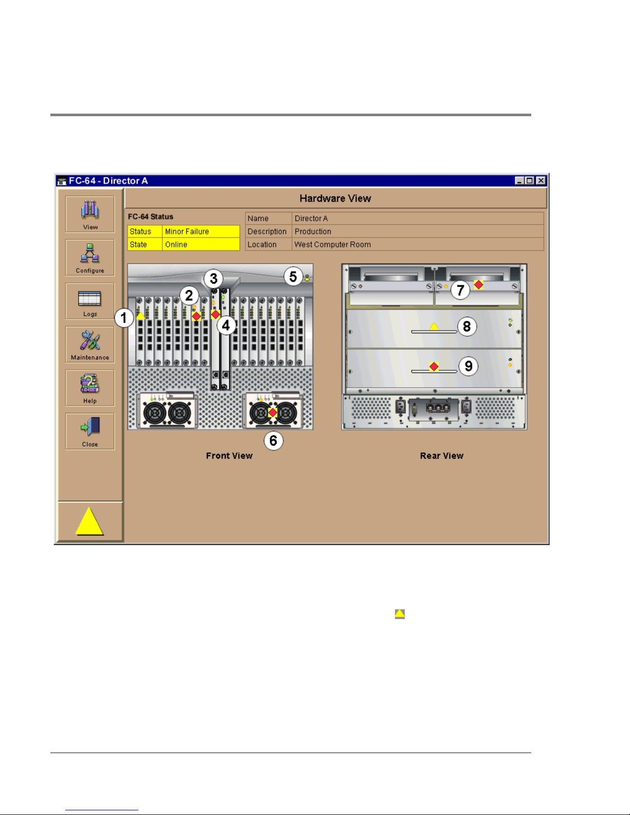
Figure 16 Monitoring Hardware Operation - HP Surestore Director FC-64 Hardware View
1. FPM card attentio n indicator: The yellow triangle alert symbol ( ) indicates that the
FPM card is in a degraded state. This could indicate a problem with an individual port,
such as a link failure or service-required status. A yellow triangle could also indicate
that a port is in beaconing state. Open the Port Card View by clicking the FPM card to
examine individual po rt status. Refer to Using the Port Card View on page 66 for details.
54 Hardware View
Page 71

2. FPM card failure indicator: The blinking red and yellow diamond displayed on the FPM
card with the amber FPM card LED illuminated may indicate that the card has failed.
This may also indic ate that an individual po rt has failed o n the card. Open the Po rt Card
View by clicking the FPM card to examine individual port status. If an individual port
has no t failed, the card is at fault.
Refer to Using the Port Card View on page 66 for details on using the Port Card View.
Refer to Table 3 fo r details o n port operating states and the alert symbol and indicator
operation.
3. CTP card failure indicator: The blinking red and yellow diamond ( ) on the CTP card
with the amber LED illuminated indicates that the card has failed.
4. Active CTP card indicator: The green LED on a CTP card illuminates to indic ate that the
card is active. Since the redundant CTP card on the left has failed, this CTP card has
beco me the active card. If both CTP cards are operational, no LEDs illuminate on the
backup card, while the green LED illuminates on the active CTP card.
5. Po wer, system error, and unit beac oning indicato rs: The green and amber indicators on
the far right of the front bezel simulate the power and system error LEDs on the actual
director bezel.
– Power Indicator. The green indic ator simulates the power LED on the actual
director. When the indicator illuminates, the director is connected to facility AC
power and is operational. The indic ator will be on if either power supply is operating.
Managing the Director
Monitoring and
– System Error Indicator. The amber system error light indicator (illuminated in
Figure 16) simulates the system error light on the actual director. When this
indicator illuminates, an event has occurred requiring immediate attention, such as
a system, fan, power supply, or port failure. View details of system errors by
selec ting Event Log fro m the Logs menu on the navigation control panel. The
indicator in the Hardware View and the LED on the actual unit remains illuminated
until you clear the event by right-clicking on the director graphic, away from a FRU,
and selecting Clear System Error Light from the pop-up menu.
Note that if the amber LED flashes, this indicates that unit beaconing has been
enabled for the director. Enable or disable unit beaconing by right-clicking on the
director graphic, away from a FRU, and selecting Enable Unit Beaconing from the
pop-up menu.
Hardware View 55
Page 72
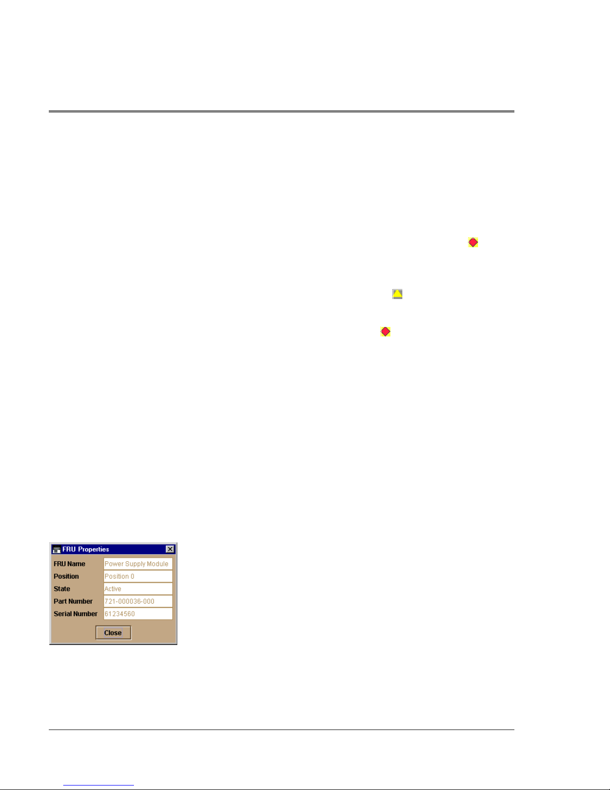
6. Power supply failure indicator: When a blinking red and yellow diamond displays on a
power supply with the amber Fault indicator illuminated, that power supply has failed.
The tandem power supply has taken over to supply DC voltage to the director.
A green indicator displays and no alert symbols appear if the power supply is working,
as shown on the left (position 1) in the illustration.
7. Cooling fan module failure indicator: When a blinking red and yellow diamond
()
displays on a fan module with the amber LED indicator illuminated, the module has
failed or is rotating insufficiently.
8. SBAR card beaconing indicator: The yellow triangle alert symbo l
() displaying on the
SBAR card with the amber LED illuminated indicates that beaconing has been enabled.
9. SBAR failure indicator: The blinking red and yellow diamond
() displaying on the
SBAR card with the amber LED illuminated indic ates a card failure.
Obtaining Hardware Information
This section explains how to access the FRU Properties, Port Properties, and Direc tor
Properties dialog boxes.
Displaying FRU Information
Click a CTP card, power supply, coo ling fan module, or SBAR card in the Hardware View to
display a FRU Properties dialog box. This dialog box displays the FRU name, slot position
relative to identical FRUs installed in the chassis, active or failed state, beaconing state
(CTP card, fan module, SBAR card) part number, and serial number.
Figure 17
56 Hardware View
FRU Properties Dialo g Bo x
Page 73

You can display a properties dialog box for all FRUs by right clicking on the FRU and
selecting FRU Properties from the menu that appears.
Display a Properties dialog box for an FPM card by right clicking on a card and selecting
FRU Properties from the menu that appears. To display a properties dialog box for an
individual port, you must be in the Port Card View. Refer to Using the Port Card View on
page 66 for details.
Managing the Director
Monitoring and
Figure 18
FPM Card FRU Properties Dialog Box
Displaying Director Information
Click on the director illustration, away from a hardware component, to display the Director
Properties dialog box as shown in the following figure.
Hardware View 57
Page 74
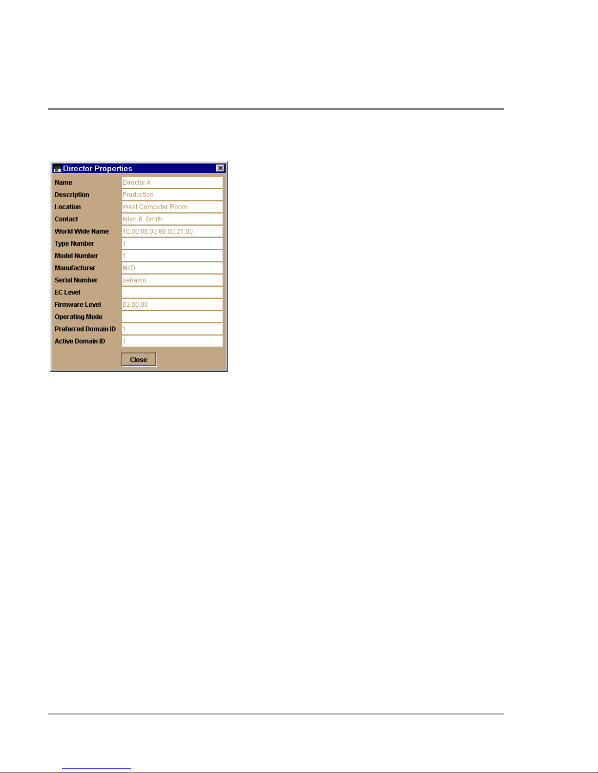
Figure 19 Direc to r Pro perties Dialog Box
The following displays in this dialog box:
• Director name, description, location, and contact configured through the Configure
Identification dialog box.
• Fibre Channel world wide name (WWN) identifier for the director.
• Product type number.
• Produc t mo del number.
• Produc t manufacturer.
• Produc t serial number.
• Engineering change (EC) level.
• Firmware level.
• Operating Mode (open systems mode displays).
58 Hardware View
Page 75

• Preferred Domain ID. This is set through the Configure Operating Parameters dialog
box.
• Active Domain ID. The actual domain ID assigned to the director.
You can also display the Director Properties dialog box by right clicking the director
illustration away from a FRU and selecting Properties from the menu.
Using Menu Options
Right click on various parts of the Hardware View to display pop-up menu options for
displaying status and information and for controlling the director and its FRUs.
Director Menu
Right clic k on any area of the director illustration where a hardware component is not
installed to display the following menu options:
Director Properties
Click to display the Director Pro perties dialog box. This dialog bo x contains the director
name, description, location, and contact person configured through the Co nfigure
Identification dialog box. Also included is other product information as detailed in
Displaying Director Information on page 57. You can also display this dialog box by clicking
an area on the illustration away from a hardware component.
Managing the Director
Monitoring and
Enable Unit Beaconing
Click the check box to toggle unit beaconing on or off. When the check box has a check
mark, unit beaconing is on, and the amber system error light on the director front bezel
blinks to help users locate the actual unit in an equipment room. When you click the check
box to remove the check mark, unit beaconing is disabled and the amber LED goes out.
Note You can o nly enable beaconing if there are no system errors ( the system error
light is off).
Hardware View 59
Page 76

Clear System Error Light
Select this to turn off the amber system error LED, located below the green power LED on
the director front bezel.
IPL Director
Select this option to initiate an IPL on the director. When the dialog box displays
confirming the IPL, click Yes.
Refer to the hp surestore director fc-64 Installation and Service Manual (HP A6534-
90902) for details.
An IPL is not intended for ordinary or casual use and should only be performed when
directed by your support personnel.
Set Director Date and Time
Select this option to display the Configure Date and Time dialog box.
1. Click to display the Configure Date and Time dialog box.
The dialog bo x displays with a chec k mark (the default) in the Periodic Date/Time
Synchronization check box. If this field is checked, the HP EFC server periodically sets
the director time to automatically synchronize with the HP EFC server time. Daylight
savings time auto matic ally updates on the director using this optio n.
The current date and time display in the Date and Time fields. If the Periodic Date/Time
Synchronization field is checked, the Date and Time fields are disabled (grayed out).
To enable and disable Periodic Date/Time Synchronization, click the check box and
then click the Activate button.
60 Hardware View
Page 77
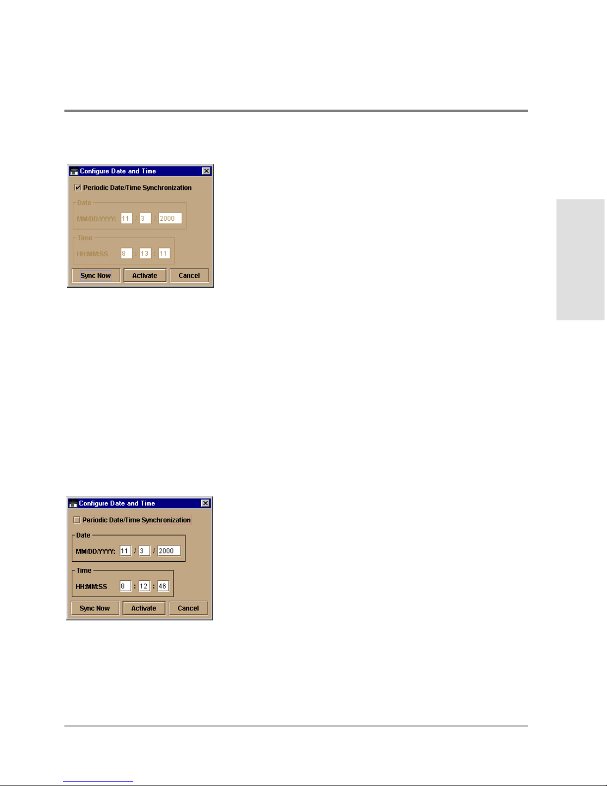
Figure 20 Configure Date and Time Periodic Synchronization Dialog Box
2. Perform one of the following steps:
– To immediately synchronize the director date and time with the HP EFC server, be
sure the Periodic Date/Time Synchronization option is enabled and then click the
Sync Now button.
If you enable the Periodic Date/Time Synchronization feature and click Activate,
the time will synchronize at the next update period.
– To set the director with a spec ific date and time, make sure that the Periodic Date/
Time Synchronization field is not selected. Refer to Figure 21. Enter the date and
time, and then clic k Activate.
Managing the Director
Monitoring and
Figure 21
Configure Date and Time (Manually)
Use the range of 0 to 23 for hours. Use the range o f 0 to 59 fo r minutes and seconds.
Hardware View 61
Page 78
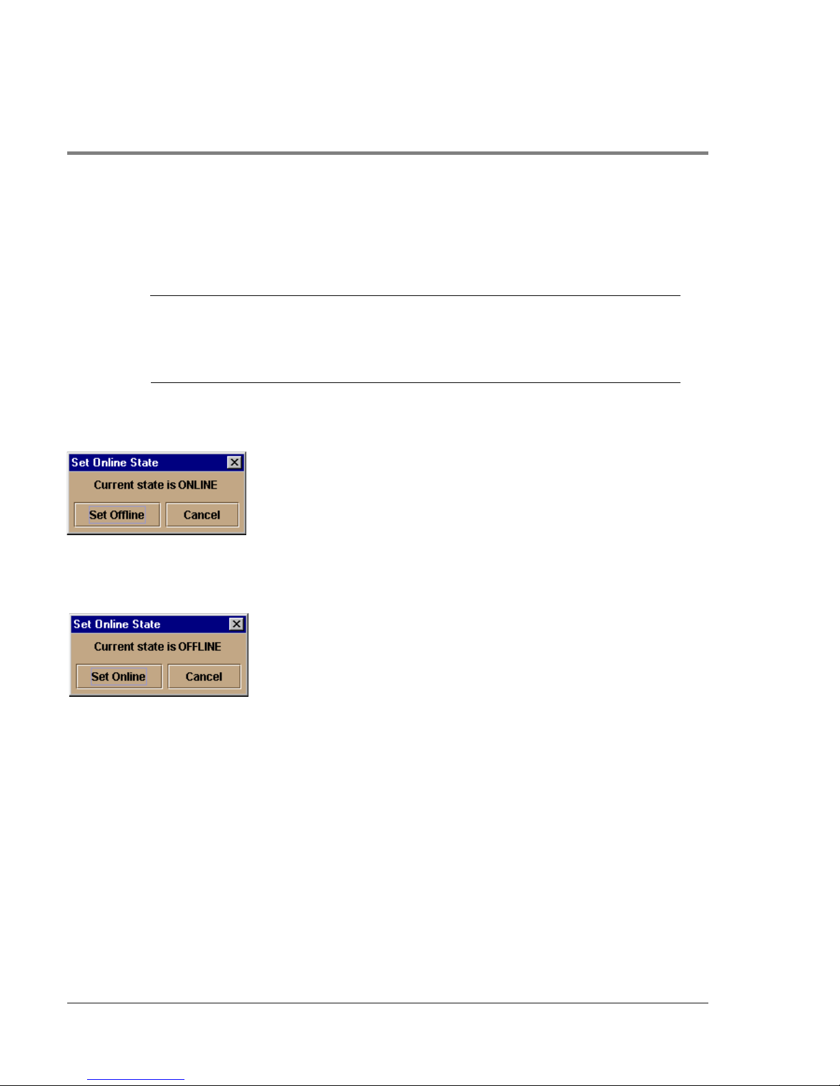
Set Director Online State
Click to display the Set Online State dialog box. The dialog bo x displays the current state
(offline or online) and provides a button for changing the state.
CAUTION Before setting the director offline, warn administrators and users currently
operating attached devices that the director is going offline and that there will
be a disruption of port operation. Also, request that the devices affected by an
interruption of data flow be set offline.
1. Click the Set Offline or Set Online button to toggle between o ffline and online states.
Figure 22
Set Online State Dialog Box (Director is Online)
Figure 23 Set Online State Dialog Box (Director is Offline)
2. When the Set Online or Set Offline warning dialog box displays, click OK to set the
director online or offline.
As the director goes offline, the word “OFFLINE” displays in the State field in the left
corner of the Hardware View. As the direc tor goes online, the word “ONLINE” displays
in the State field in the left corner of the Hardware View. When going offline, LED
indicato rs on all ports with attached devic es stay green, but the director sends offline
sequences (OLS) to these devices.
62 Hardware View
Page 79

FPM Card Menu
Right clic k a FPM c ard in the Hardware View to display the following menu options.
• Open Port Card View
Select this optio n to o pen the Port Card View. You can also open the Port Card View by
clicking on the FPM card. See Using the Port Card View on page 66 for detailed
information.
• FRU Properties
Select this option to display the FPM card’s Properties dialog box. This dialog box
includes the FRU name, position (slot number in backplane), state (active or failed),
beaconing state ( o n or off) part number, and serial number (see Figure 18).
• Enable Beaconing
Select this option to add a check mark to the check bo x and enable beaconing for the
card. This causes the amber LED on the card to flash to help yo u lo c ate the card in the
unit.
• Block All Ports
Select this option to display the Block All Ports dialog box. Click Yes to block all ports
on the selected card or No to cancel.
• Unblock All Ports
Managing the Director
Monitoring and
Select this option to display the Unblock All Ports dialog box. Click the Yes button to
unblock all ports on the selected card or click No to cancel.
• Diagnostics
Select this optio n to display the Port Diagnostics dialog box. Use this dialog box to run
internal loopback and external loopback tests on any port or all ports on the FPM card.
Port Menu
To display the a menu of options for a port on a FPM card, open the Port Card View by
clicking on a port on the FPM card. Refer to Port Menu on page 73 under Using the Port
Card View on page 66 for details on displaying and using the port menu.
Hardware View 63
Page 80
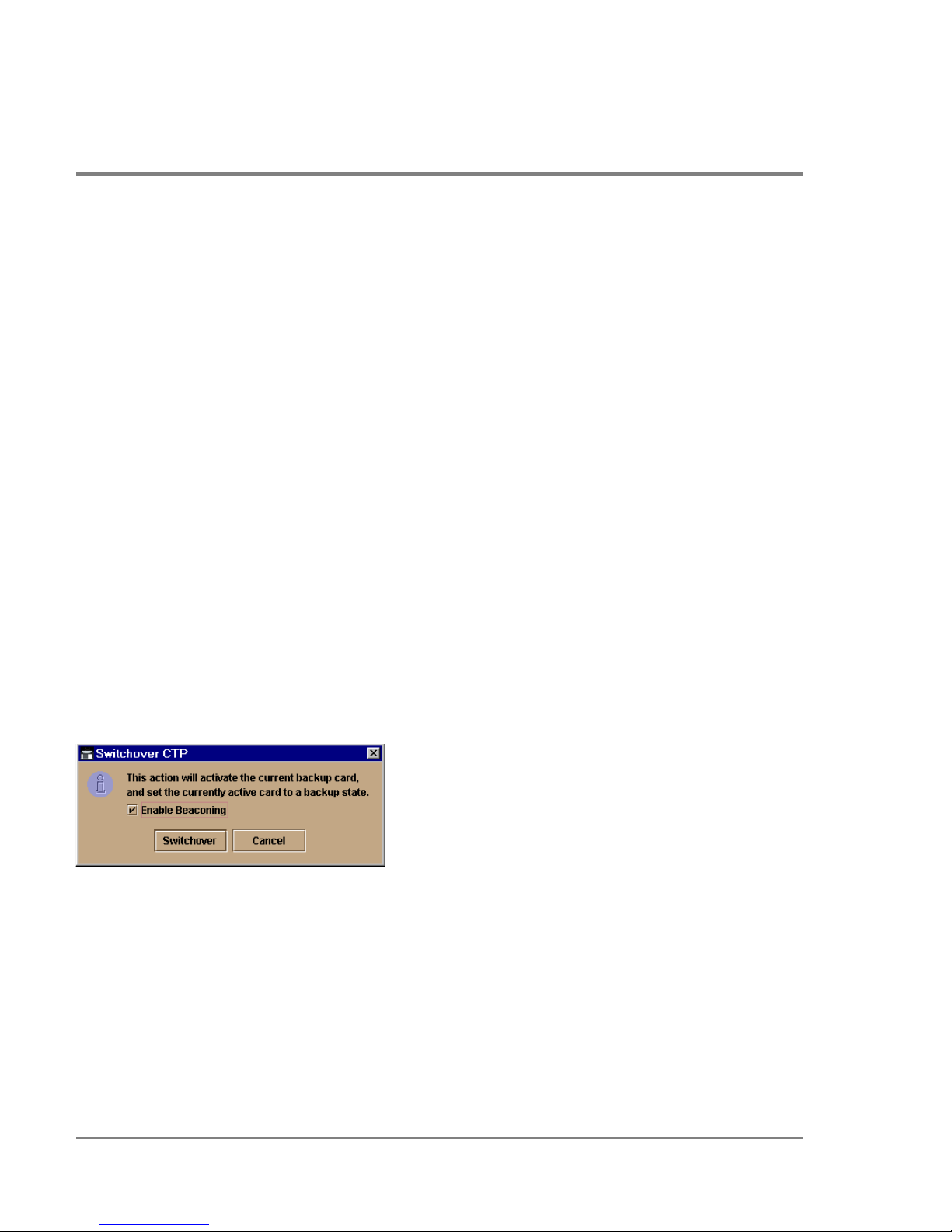
CTP Card Menu
Right clic k the CTP card in the Hardware View to display a menu with the following
options:
• FRU Properties
Select this option to display a FRU Properties dialog bo x for the CTP card. Figure 17 is
an example for the power supply module. The FRU Properties dialog box includes the
FRU name, position (slot number in the backplane), state (active, backup, or failed),
part number, and serial number.
• Beaconing
Select this option to add a check mark to the check bo x and enable beaconing for the
CTP card. This causes the amber LED on the card to flash to help you locate it in the
unit.
• Switchover
You must have maintenanc e authorization rights to access this feature.
Select this option to display the Switchover CTP dialog box. Click the Switchover
button to switch operation from the ac tive card to the backup card. When switchover
occurs, the green LED illuminates on the backup CTP card to indic ate that it is active.
Figure 24
Switc hover CTP Dialog box
If you click the Enable Beaconing check box to add a check mark, the amber LED
beacons (blinks) on the card that was the active card before switchover.
If a redundant card has failed, or is not installed, selecting the Switchover button
displays an error message explaining that two operational cards must be installed to
use this feature.
64 Hardware View
Page 81

Fan Module
Click a co oling fan module card in the Hardware View to display the FRU Properties dialog
box:
Figure 17 is an example for the Properties dialog box for the power supply module. For the
fan, the FRU name will be “Cooling Fan Mode,” position (slot number in the backplane)
will be 1 or 0, and the state will be active, backup, or failed. The appropriate fan part
number and serial number will also be included.
SBAR Card Menu
Right clic k an SBAR card in the Hardware View to display a menu with the following
options:
• FRU Properties
Select this option to display a FRU Properties dialog box for the card. Figure 17 is an
example for the power supply module. The FRU Properties dialog box includes the
FRU name, position (slot number in the backplane), state (active, backup, or failed),
part number, and serial number.
• Enable Beaconing
Managing the Director
Monitoring and
Select this option to add a check mark to the check bo x and enable beaconing for the
SBAR card. This causes the amber LED on the card to flash to help yo u loc ate it in the
unit.
• Switchover
You must have maintenanc e authorization rights to access this feature.
Select this option to display the Switchover SBAR dialog box which is similar to the
Switchover CTP dialog box (refer to Figure 24). Click Switchover to switch operation
from the active card to the backup card. When switchover occurs, the green LED
illuminates on the backup SBAR card to indicate that it is now the active card.
If you click the Enable Beaconing check box to add a check mark, the amber LED
beacons (blinks) on the card that was the active card before switchover.
Hardware View 65
Page 82
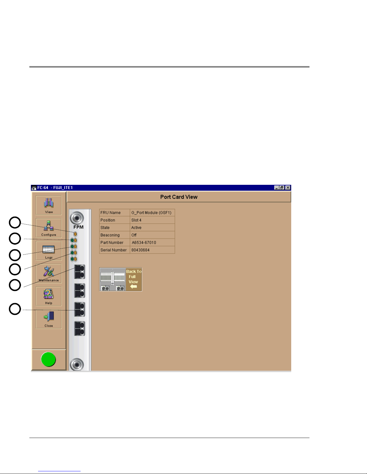
Using the Port Card View
In the Hardware View, click an FPM card or right-click and select Open Port Card View to
see a detailed view of the FPM card. In the Port Card View, colored indicators reflect
functions of the actual LEDs on the card. The table in the Port Card View displays the port
operating state and vital product information.
Symbols and Indicators
The following figure illustrates the alert symbols and LED indicators that may display on a
FPM card in the Port Card View.
1
2
3
4
5
6
Figure 25
66 Hardware View
Port Card View
Page 83

Refer to the following numbered list for the meaning of the alert symbols and LED
indicators shown on the Port Card View in Figure 25. Port states are described in detail
under Port Operational States on page 98.
1. The amber indicator at the top of a FPM card illuminates when the FPM card fails. An
FPM card fails when one or more individual ports fail.
Four sets of green and amber LEDs beneath the amber card status indic ator
correspond to the four port co nnectors installed vertically down the FPM card.
2. In Figure 25, the amber LED is blinking (while the green LED is on) for the first port on
the card, and a yellow triangle displays by the port’s connector. This indicates that
beaconing is enabled for the port and the port is an online state. Note that if the amber
port indicator flashes and the green indicator is off, the port is running diagnostics.
The green indicator illuminates when the port is online with an attached device and
fully operational. The green port LED remains on as long as the port remains in the
online state. The green LED on the physical card flashes when there is active Fibre
Channel traffic through the port. It do es no t flash in the Port Card View.
3. When the port is operational but not communicating with an attached device, the green
indicator remains off. In this case, there may not be a fiber cable attached, no light from
the device (the device switch is powered off), the port may be blocked, or the link may
be recovering.
4. If the port fails, the amber indicator for port illuminates and a blinking red and yellow
diamond displays next to the port connector.
Managing the Director
Monitoring and
5. A yellow triangle (attention indicator) displays next to a po rt connector for a variety of
reasons:
Beaconing for the po rt was enabled through the Enable Beac oning o ption. Note that
this is the case in Figure 25 (refer to number 1 in the figure).
The port is rec eiving the Not Operational sequenc e from the attached device.
The port has an invalid attachment.
The director and attached device are performing a link reset operation.
Hardware View 67
Page 84

LIN alerts have been enabled for a port in the Configure Ports dialog box and a link
incident occurs.
A threshold alert has o ccurred fo r the port.
Diagnostics are running on the port.
6. The Port Card View indicates a failed port by a blinking red and yellow diamond alert
symbol by the port’s connector. The amber LED fo r the port will also illuminated (refer
to number 4 in Figure 25).
Displaying Port Information
Click a port or right click on a port and select Port Properties from the menu to display the
port’s Properties dialog box. Also display this dialog box by:
• Clicking on a row in the Port List View or right clicking on a row and selecting Port
Properties from the menu.
• Clic king o n a port’s bar graph in the Performance View or right clicking on the bar graph
and selecting Port Properties from the menu.
• Right-clicking on a port’s row in the Node List View and selecting Port Properties from
the menu.
68 Hardware View
Page 85

Figure 26 Port Properties Dialo g Bo x
The following paragraphs describe the fields in the Port Properties dialog box.
• Port Number
The physical port number.
• Port Name
Managing the Director
Monitoring and
User-defined po rt name or description. Refer to Configure Po rts on page 115 fo r
instructions.
• Type
– G_port. This displays if nothing is logged into the port.
– F_Po rt. This displays if a device is logged into the port.
– E_Port. This displays if the po rt is connected to another director’s E_Port via an ISL.
• Fibre Channel Address
The port’s Fibre Channel address identifier.
Hardware View 69
Page 86

• Port WWN
The port’s 16-digit world wide name (WWN).
• Attached Port WWN
The WWN of the node lo gged into the port.
• Block Configuration
Blocked or unblocked. Operatio n can be blocked or unblocked through the Configure
Ports dialog box or through the block ports options on right-click menus in the Port
Card View. Refer to Configure Ports o n page 115 and Using the Port Card View on page
66 for details.
• 10-100 km Configuration
Extended distance buffering. This can be enabled o r disabled fo r the port thro ugh the
Configure Ports dialog box. Refer to Configure Ports on page 115 for instructions.
• LIN Alerts Configuration
This field indicates whether LIN alerts are enabled or disabled. LIN alerts can be
configured through the Configure Ports dialog box. The default is for the LIN alerts to
be enabled.
• Beaconing
This field indicates the beaconing status for the port. To enable or disable beaconing,
right click the po rt and select Enable Beaconing.
• Link Incident
Description of the last link incident that occurred on the port.
• Operational State
Online, offline, no light, link down, link recovery, testing, or failed. Refer to Table 3 for
definitions of operational states.
• Reas on
Lists the reason for a segmented E_Port operating state or for an invalid attachment
operating state for the port. An E_Port segmentation only occurs when the director is
70 Hardware View
Page 87

connected to another director or a switch. This field displays “NA” if a segmented
E_Port or invalid attachment o perating state has not occurred.
Refer to the section on joining zoned fabrics in the hp surestore director fc-64
Planning Guide (A6534-90903).
Reason messages for segmentation can include:
– Incompatible operating parameters. Operating parameters, such as resource
allocatio n time-out values (R_A_TOV) or error-detect time-out values (E_D_TOV),
are inconsistent. Refer to Configure Operating Parameters on page 110 fo r more
information.
– Duplicate domain IDs. Identical preferred domain IDs are configured for two or
more directors or switches. Refer to Configure Operating Parameters on page 110
for more information.
– Incompatible zoning configurations. Refer to the hp surestore director fc-64
Planning Guide (HP A6534-90903) and the hp surestore director fc-64 Installation
and Service Manual ( HP A6534-90902) fo r more information on zoning.
– Build fabric protocol error.
Managing the Director
Monitoring and
– No principal switch. A principle switch is not defined for the fabric.
– No response from the attached switch.
Reason messages for an invalid attachment can include:
– 01 Un known . The reason is not known.
– 02 ISL connection not allowed on this port. ISL is connected to a port configured as
an F_Port.
– 03 ELP rejected by the attached switch. This director or switch transmitted an
exchange link protocol (ELP) frame that was rejected by the switch at the other end
of the ISL.
– 04 Incompatible switch at other end of the ISL. The switch is configured for Open
Fabric mode, and the switch at the other end of the ISL is a McDATA switch
configured for McDATA Fabric mo de.
Hardware View 71
Page 88

– 05 External loopback adapter connected to the port. A loopback plug is connected
to the port, and no diagnostic test running.
– 06 N_Port connection not allowed on this port. The port type configuration does not
match the actual po rt use ( the po rt is co nfigured as an E_Port, but attaches to a node
device).
– 07 Non_McDATA switch at other end of the ISL. The cable is connected to a non-
McDATA switch, and interop mode is set to McDATA Fabric mode.
– 08 ISL connection not allowed on this port. The port type configuration does not
match the actual po rt use (the port is configured as an F_Port, but attaches to a
director or switch).
– 10 Port binding violation - Unauthorized WWN. The WWN that was entered to
configure port binding for this port is no t valid, or a nickname was used that was not
configured for the attached device in the Pro duct Manager or Fabric Manager.
– 11 Unresponsive node connected to port. Possible causes are: (1) a hardware
problem on a switch or connected node where ELP frames are not delivered; the
response is no t received, or a fabric lo gin (FLOGI) c annot be rec eived ( there may be
problem in the switch SBAR); (2) a faulty or dirty cable connection; (3) faulty host
bus adapters that do not send out a FLOGI within a reasonable timeframe.
• Threshold Alert
If a threshold alert exists for the port, an alert indicator (yellow triangle) will appear by
the Threshold Alert field, and the configured name for the last alert received will
appear in the field.
Port Card Menu
While in the Port Card View, right-click on the card away from a port c onnector to
display a pop-up menu of port card functions.
• Block All Ports
Select this option to display the Block All Ports dialog box. Click Yes to block all ports
on the selected card or click No to cancel.
72 Hardware View
Page 89

• Unblock All Ports
Select this option to display the Unblock All Ports dialog box. Click Yes to unblock all
ports on the selected card or No to cancel.
• Diagnostics
Select this optio n to display the Port Diagnostics dialog box. Use this dialog box to run
internal loopback and external loopback tests on any port or all ports on the FPM card.
Refer to the hp surestore director fc-64 Installation and Service Manual (HP A6534-
90902) for instructions on using these diagnostics.
Port Menu
While in the Port Card View, right-click on any port to display the following menu options:
Port Properties
Click this to display the Port Properties dialog box. This dialog bo x displays information
about the port. See Displaying Port Information on page 68 for more information.
Node Properties
Managing the Director
Monitoring and
Click this to display the Node Properties dialog box. Note that if a node is not logged into
the port, a message appears indicating that node information is not available. For details on
info rmatio n that displays in this dialog box, refer to Displaying Node Properties on page 87.
Port Technology
Click this to display the Port Technology dialog box. This dialog bo x displays the following
information:
• Port number
• Connector type: Always LC.
• Transceiver type: Longwave laser LC or shortwave laser LC.
• Distance: General distance range for port transmission. This can be either short to long
distances for the longwave laser LC transceiver or short distances for the shortwave
laser LC transceivers.
Hardware View 73
Page 90

• Media: The Fibre Channel mode and optic size. For the longwave laser LC transceiver,
this would be singlemode 9 micron. For the shortwave laser LC transceiver, this would
be multimode 50-micron or 62.5-micron.
• Speed: This will always be 1 Gbit per second.
Block Port
Click to display a check mark and block port transmission. If blocked, a node attached to
the port is prevented from logging into the director or communicating with other devices
attached to director ports. A blocked port continuously transmits offline signals (OLS).
Click to remove the c heck mark and unblock the port. If unblocked, a node attached to the
port can communicate with the director and communicate with other nodes attached to the
director.
Enable Beaconing
Click this to make the amber LED by the port blink on the actual director and the amber
indicato r blink for the port in the Hardware View. This enables users to locate the unit
where the port is located. When a blinking amber LED indicator displays by a port, an
attention indicator ( ) displays below the port’s connecto r in the Port Card View, Port List
View, and on the FPM card in the Hardware View.
Diagnostics
Click this option to display the Port Diagnostics dialog box. Use this dialog box to run an
internal loopback and external loopback test on the port. The Port Diagnostics option
enables you to run internal and external loopback tests on any port or all ports on an FPM
card. To use this option, follow the detailed steps in the hp surestore director fc-64
Installation and Service Manual (HP A6534-90902).
Clear Link Incident Alerts
Click this to clear the attention indicator on the Hardware View, the Port List View, and the
Performance View. In addition, the procedure clears the alert description in port Properties
dialog boxes. If there are no link incident alerts set for a port, no actions occur. Although
you can manually clear link incidents, they may also be cleared by actions outside of the
user interface, such as when rebooting the HP EFC server.
74 Hardware View
Page 91
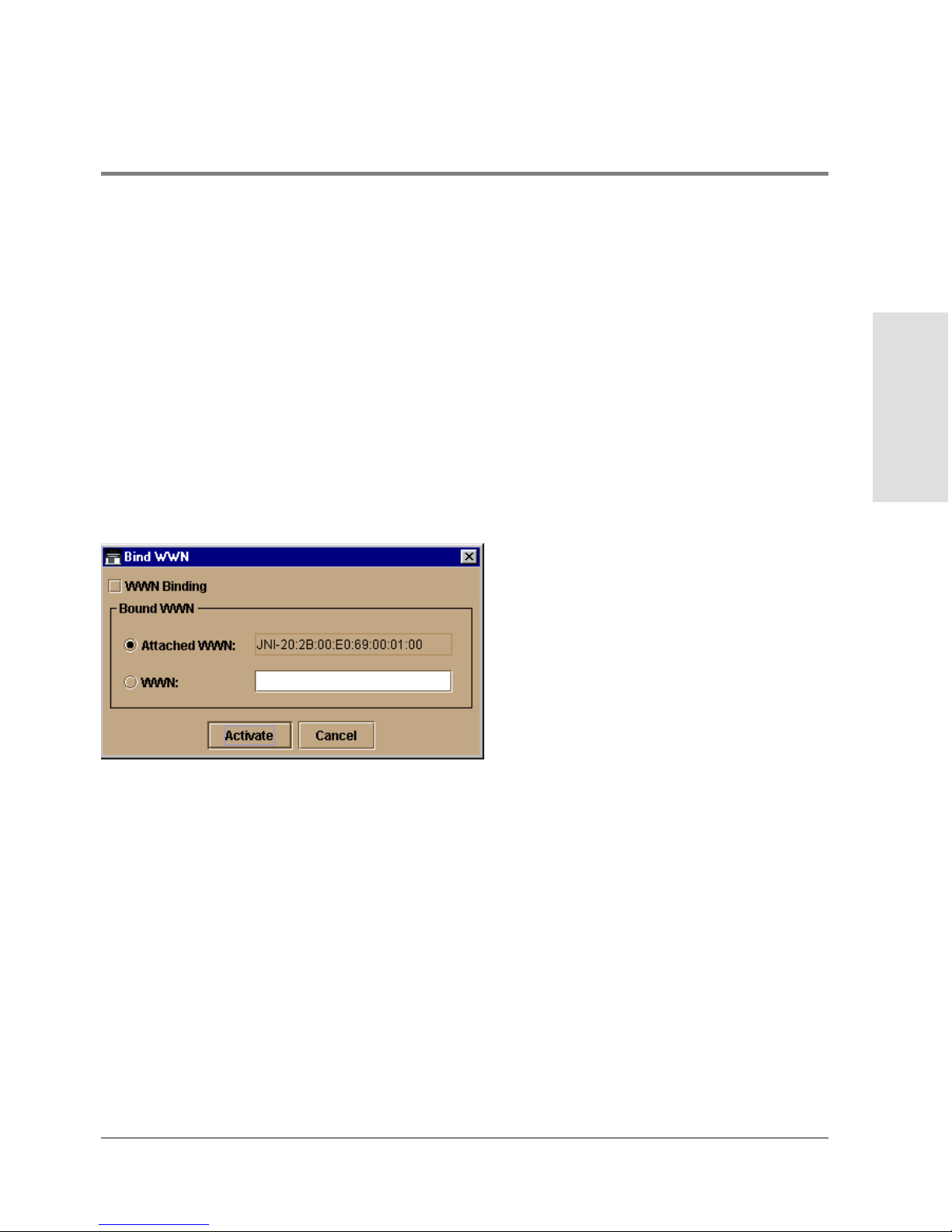
Reset Port
Click to display a confirmation dialog box. Click Yes on the dialog box to reset the port. If a
switch is attached to the port and o nline, this operation sends a link reset to the attached
switch; otherwise, this action disables port beaconing for the port. If the port is in a failed
state, such as after failing a loopback test, the reset restores the port to an operational
state, clearing the service required (amber) LED. The reset does not affect other ports in
the director.
WWN Binding
Click to display the Bind WWN dialog box Figure 27. Use this dialog box to allow a device
with a specific WWN or nickname to have exclusive communication privileges over a port.
To use this dialog box, refer to the following paragraphs.
Managing the Director
Monitoring and
Figure 27
Bind WWN Dialog Box
Bind WWN dialog box parameters:
• WWN Binding: Click to place check mark in the box and enable WWN binding for the
port. When enabled, only a specific device can communicate through the po rt.This
device is specified by the WWN or nickname entered into the Bound WWN field (either
the Attached WWN or WWN options) . With the check box cleared, any device can
communic ate through the port even if a WWN or nickname is specified in the Bo und
WWN field.
Hardware View 75
Page 92

• Attached WWN: Click the radio button and, if a device is logged into the port, the
device’s WWN will display in the field. The device with this WWN or nickname will have
exclusive communication privileges to the port if WWN Binding is enabled.
If yo u click this radio button to bind the port to a logged-in device and there are no
devices logged in, the port is essentially bound to a WWN of “0.” This prevents any
device from logging in until this button is re-enabled to bind the WWN of a logged-in
device or until you explicitly bind the WWN of a device by clicking the WWN radio
button and entering a WWN o r nic kname (see the following). Changes only take effect
when you click the Activate button.
• WWN: Click the radio button and enter a world wide name (WWN) in the proper format
(xx.xx.xx.xx.xx.xx.xx.xx) or a nickname configured through the Product or Fabric
Manager applications. The device with this WWN or nickname will have exclusive
communication privileges through the port if WWN Binding is enabled.
Note the following:
– If you do not enter valid WWN or nickname in this field, but the WWN Binding check
bo x is checked (enabled) , then no devic es c an c o mmunicate over the port.
– If you enter a WWN or nic kname in this field and do no t place a c heck in the WWN
Binding checkbox, the WWN or nickname will be stored, and all devices can
communicate o ver the port.
• Activate: Click to activate settings in this dialog box.
WWN Binding warning and error message display:
• If one or more of the nodes logged into a port does not match the WWN or nickname
configured in the field by the WWN radio button, a warning dialog box displays after you
activate the configuration. This warning box displays a list of all nodes that will be
logged o ff if you continue. If you Continue, these nodes will be logged off and the port
will only attach to the device with the device with the WWN or nickname configured in
the WWN field.
• An error message displays after you ac tivate the c o nfiguration if the format for the
WWN entered in the WWN field is not valid (not in xx.xx.xx.xx.xx.xx.xx.xx format) or
if you have entered a nickname that was not configured through the Produc t o r Fabric
Manage r.
76 Hardware View
Page 93
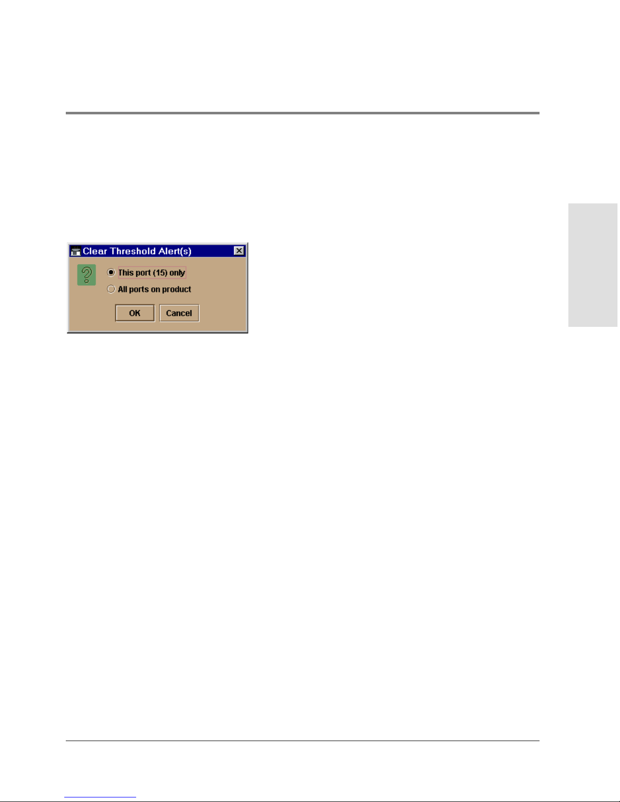
Clear Threshold Alert( s)
Click this to display the Clear Threshold Alert(s) dialog box. Select the appropriate option
to clear alerts for the selected po rt only or all ports on the director. This clears all attention
indicato rs that notify users of threshold alerts in dialog boxes and views. This action also
restarts the notification interval and the cumulative minutes for utilization % interval.
Managing the Director
Monitoring and
Figure 28
Clear Threshold Alert(s) Dialog Box
Hardware View 77
Page 94
Port List View
Display the Port List View (Figure 29) in the main panel by selecting the Port List option
from the View menu.
Figure 29
The Port List View displays the following information on all ports that can be installed in
the director. All information is updated automatically.
Port List View
• #
Number of the port from 0 through 63.
78 Port List View
Page 95

• Name
Displays the po rt name as configured through the Configure Ports dialog box.
• Block Config
Indicates the blocked or unblocked configuration of the port as set through:
– The Configure Ports dialog box.
– The Blo c k Po rt o ption available through port right-c lick menus in the Port Card
View, Block All Ports option on the FPM card right-click menus in the Po rt Card View
and Hardware View, port row right-c lick menus in the Port List view, and the port bar
graph right-clic k menus in the Performanc e View.
Blocked states are:
– Blocked: Devices communicating with the port are prevented from logging into the
director or communicating with other devices attached to director ports. A bloc ked
port continuously transmits OLS.
– Unblocke d: Devices communicating with the port can log into the director and
communicate with devices attached to any other unblocked port in the same zone.
• State
The following port operational states may display in this table. For more information
on these states and corresponding alert symbol and LED indicator operations in the
Hardware View, see Port Operational States on page 98.
Managing the Director
Monitoring and
– No Light
– Online
– Offline
– Beaconing
– Link Re set
– Not Operational
– Not Installed
Port List View 79
Page 96

– Invalid Attachment
– Port Failure
– Segmented E_Po rt
• Type
The type of port.
– It is an F_Port if an N_Port is attached.
– It is an E_Port if another E_Port is attached.
– It is a G_Port if the port is capable of acting as either an F_Port or an E_Port, but
nothing is currently attached.
• Alert
This column displays a yellow triangle if a link incident occurs on the port or if the
port’s LED is beaconing. Blinking red and yellow diamonds display for port failures or
for ports requiring service. Clic k on the row to display the reason for the alert in the
Port Properties dialog box.
Click a row to select it, highlight it, and display the Port Properties dialog box. For an
explanation of the fields on the Port Properties dialog box, refer to Displaying Port
Information on page 68.
Menu Options
Right clic k a row to select it, highlight it, and display a menu with the following port-related
action options. These are the same menu options that display when you right click a port in
the Port Card View and Performance View. Refer to Port Menu on page 73 for an
explanation of these menu options.
• Port Properties
• Node Pro perties
• Port Tec hno logy
• Block Po rt
80 Port List View
Page 97

• Enable Beaconing
• Diagnostics
• Clear Link Incident Alert
• Reset Port
• WWN Binding
• Clear Threshold Alert(s)
For Node Properties, if a node is not logged in a message displays indicating that node
information is not available.
Managing the Director
Monitoring and
Port List View 81
Page 98
FRU List View
Display the FRU List in the main panel selecting the FRU List option from the View menu.
This view displays information about all installed FRUs on the director. All data is dynamic
and updates automatically as the software detects changes.
Figure 30
Info rmation on the FRU List View fo r each FRU includes:
82 FRU List View
FRU List View
Page 99

• FRU - an acronym representing the FRU type. The meanings of FRU acronyms are:
– BKPLNE - backplane.
– CTP - CTP card.
– SBAR - SBAR card.
• FPM card. For the fiber port module (FPM) card, the following acronyms may display
to indic ate the card’s port technology:
– GLSL - G_Port, long wave, single mode LC connector, 1 Gigabit
– GSML - G_Port, short wave, multimode, LC connector, 1 Gigabit
– GXXL - G_Port, mixed mode, LC connector, 1 Gigabit
– GSF1 - G_Po rt, small form factor optics (SFO) pluggable, 1 Gigabit
– GSF2 - G_Po rt, small form factor optics (SFO) pluggable, 2 Gigabit
– GLSR - G_Port, short wave, single mode, MT-RJ connector, 1 Gigabit
– GXXR - G_Port, mixed mode, MT-RJ connector, 1 Gigabit
– GXXL - G_Port, mixed mode, LC connector, 1 Gigabit
• FAN - fan module.
• PWR - power supply.
Managing the Director
Monitoring and
Position - a number representing the FRU chassis position. The chassis (slot) position
for a nonredundant FRU is 0. The chassis positions for redundant FRUs are 0 and 1.
The chassis positions for FPM cards are 0 through 15.
Status - the FRU status (Active or Backup).
Part Number - the FRU part number.
Serial Number - the FRU serial number.
FRU List View 83
Page 100
Node List View
Display the Node List View in the main panel by selecting Node List from the View menu.
This view displays info rmation about all node attachments to any F_Ports on the director
sorted by port number. All data is dynamic and updates automatically as devices log in and
log out.
Figure 31
84 Node List View
No de List View
 Loading...