

Page 1

getting started guide
hp surestore
fc 1Gb/2Gb entry switch 8B
and fc 1Gb/2Gb switch 8B
www.hp.com
Page 2

Notice
Safety notices
© Hewlett-Pack a rd C om pa n y, 2001. All rights rese r v ed .
Part number: A7346-96002
Edition: E1201
Hewlett-Packard Company makes no warranty of any
kind with regard to this material, including, but not
limited to, the implied warranties of merchantability and
fitness for a particular purpose. Hewlett-Packard shall not
be liable for errors contained herein or for incidental or
consequential damages in c o nn ectio n with the furnish in g,
performance, or use of this material.
This document conta in s p rop rie ta ry info rm at ion , whic h is
protected by copyr ight. No part of this document may be
photocopie d, reproduced, or translated into another
language without the prior written consent of
Hewlett-Packard. The i nformation contained in this
document is subject to change without notice.
Use, duplication, or disclosure by government is subject
to restrictions as set forth in subdivision (c) (1) (ii) of the
Rights in Technical Data and Computer Software Clause
at DFARS 252.227.7013.
Any servicing , adjustme nt, mainte nance, or re pair must be
performed only by authorized service-trained personnel.
Format convention s
variable Indicates that you must supply a value.
output Denotes text displayed on the screen.
[ ] Indicates that the enclo sed element is
optional and may be left out.
{ } Indicates that you must specify one of the
listed options.
| Separates alternatives.
. . . Indicates a repetition of the precedi ng
parameter.
Tip Denotes ideas for enhanced product usage.
Note De no te s significa nt con cep ts or operat ing
instructions.
Warranty
If you have any ques tions about the warranty for this
product, contact your dealer or local Hewle t t-P ackard
sales representative.
Trademarks
BROCADE, the Brocade B weave logo, Brocade: the
Intelligent Platform for Networking Sto rag e, Silk Worm,
and SilkWorm Express, are trademarks or registered
trademarks of Brocade Communications Systems, Inc. or
its subsidiaries in the United States and/or in other
countries.
All other brands, product or service names are or may be
trademarks or service marks of, and are used to identify
products of servi ces of their respe c tive owners.
CAUTION Denotes a hazard that can cause hardware or
software damage.
WARNING Denotes a hazard that ca n cause personal
injury or death.
Page 3

CONTENTS
Revision History . . . . . . . . . . . . . . . . . . . . . . . . . . . . . . . . . . . . . . . . . . . . v
Updates . . . . . . . . . . . . . . . . . . . . . . . . . . . . . . . . . . . . . . . . . . . . . . . . . . . v
Related Publications . . . . . . . . . . . . . . . . . . . . . . . . . . . . . . . . . . . . . . . . . v
1 Installing the Switch . . . . . . . . . . . . . . . . . . . . . . . . . . . . . . 1
Product Description . . . . . . . . . . . . . . . . . . . . . . . . . . . . . . . . . . . . . . . . . 1
Safety Guidelines . . . . . . . . . . . . . . . . . . . . . . . . . . . . . . . . . . . . . . . . . . . 2
Package Contents . . . . . . . . . . . . . . . . . . . . . . . . . . . . . . . . . . . . . . . . . . . 3
Installing the Switch as a Stand-Alone Unit . . . . . . . . . . . . . . . . . . . . . . . 3
Installing the Switch in a Rack . . . . . . . . . . . . . . . . . . . . . . . . . . . . . . . . . 4
2 Setup . . . . . . . . . . . . . . . . . . . . . . . . . . . . . . . . . . . . . . . . . 19
System Components . . . . . . . . . . . . . . . . . . . . . . . . . . . . . . . . . . . . . . . . 19
SFP Media Side . . . . . . . . . . . . . . . . . . . . . . . . . . . . . . . . . . . . . . . . . 20
Fan Side . . . . . . . . . . . . . . . . . . . . . . . . . . . . . . . . . . . . . . . . . . . . . . . 21
Power Supply . . . . . . . . . . . . . . . . . . . . . . . . . . . . . . . . . . . . . . . . . . . 21
Fabric Operating System . . . . . . . . . . . . . . . . . . . . . . . . . . . . . . . . . . 22
SFPs . . . . . . . . . . . . . . . . . . . . . . . . . . . . . . . . . . . . . . . . . . . . . . . . . . 22
Fibre Channel Cable Connections . . . . . . . . . . . . . . . . . . . . . . . . . . . 22
Configuring and Connecting the Switch . . . . . . . . . . . . . . . . . . . . . . . . . 23
Saving the System Configuration Files . . . . . . . . . . . . . . . . . . . . . . . . . . 28
Backing up the Switch Configuration Settings . . . . . . . . . . . . . . . . . 28
Restoring the System Configuration Settings . . . . . . . . . . . . . . . . . . 29
iii
Page 4

Next Steps . . . . . . . . . . . . . . . . . . . . . . . . . . . . . . . . . . . . . . . . . . . . . . . . 30
Setting QuickLoop Mode on Ports . . . . . . . . . . . . . . . . . . . . . . . . . . 30
Setting Up Speed Negotiation . . . . . . . . . . . . . . . . . . . . . . . . . . . . . . 30
Configuring Supported Devices . . . . . . . . . . . . . . . . . . . . . . . . . . . . 31
3 Diagnostics . . . . . . . . . . . . . . . . . . . . . . . . . . . . . . . . . . . . 35
Switch Status Indicators . . . . . . . . . . . . . . . . . . . . . . . . . . . . . . . . . . . . . 35
LEDs on the SFP Media Side . . . . . . . . . . . . . . . . . . . . . . . . . . . . . . 36
LEDs on the Fan Side . . . . . . . . . . . . . . . . . . . . . . . . . . . . . . . . . . . . 39
Maintenance and Diagnostic Tests . . . . . . . . . . . . . . . . . . . . . . . . . . . . . 40
Error Messages . . . . . . . . . . . . . . . . . . . . . . . . . . . . . . . . . . . . . . . . . . . . 42
Getting Support . . . . . . . . . . . . . . . . . . . . . . . . . . . . . . . . . . . . . . . . . . . . 43
Service and Support . . . . . . . . . . . . . . . . . . . . . . . . . . . . . . . . . . . . . . 43
Additional Licenses . . . . . . . . . . . . . . . . . . . . . . . . . . . . . . . . . . . . . . 43
4 Specifications . . . . . . . . . . . . . . . . . . . . . . . . . . . . . . . . . . 45
General . . . . . . . . . . . . . . . . . . . . . . . . . . . . . . . . . . . . . . . . . . . . . . . . . . 45
Environmental . . . . . . . . . . . . . . . . . . . . . . . . . . . . . . . . . . . . . . . . . . . . . 46
Dimensions . . . . . . . . . . . . . . . . . . . . . . . . . . . . . . . . . . . . . . . . . . . . . . . 47
Power Supply . . . . . . . . . . . . . . . . . . . . . . . . . . . . . . . . . . . . . . . . . . . . . 47
Product Regulatory Information . . . . . . . . . . . . . . . . . . . 49
iv Getting Started Guide
Page 5

Revision History
December 2001 First release.
Updates
For the most current information about the HP Surestore FC 1Gb/2Gb
Entry Switch 8B and FC 1Gb/2Gb Switch 8B, visit the support Web site
located at
For information ab out produ ct avai labil ity, configurat ion, and co nnecti vity,
consult your HP account representative.
Related Publications
Related product information can be found in the following publications.
Those publications with part numbers are provided as printed copies with
your product. The FC Entry Switch 8B and FC Switch 8B Documentation
CD contains all publications listed in the table below and is also provided
with your product. These publications are also available at
http://www.hp.com/support/fc8B.
http://www.hp.com/support/fc8B.
Title Part Number
HP Surestore FC 1Gb/2Gb Entry Switch 8B and FC
1Gb/2Gb Switch 8B Getting Started Guide
HP Surestore FC 1Gb/2Gb Entry Switch 8B and FC
1Gb/2Gb Switch 8B Documentation CD
HP Surestore FC 1Gb/2Gb Entry Switch 8B and FC
1Gb/2Gb Switch 8B Installation and Reference Guide
Fabric OS Reference Manual, version 3.0 Available on CD
Fabric OS Procedures Guide, version 3.0 Available on CD
Fabric OS Version 3.0.1b Release Notes Available on CD
Fabric Watch User’s Guide, version 3.0 Available on CD
QuickLoop User’s Guide, version 3.0 Available on CD
A7346-96002
A7346-11001
Available on CD
v
Page 6

Title Part Number
Web Tools User’s Guide, version 3.0 Available on CD
Distributed Fabrics User’s Guide, version 3.0 Available on CD
Zoning User’s Guide, version 3.0 Available on CD
MIB Reference Manual, version 3.0 Available on CD
ISL Trunking User’s Guide, version 3.0 Available on CD
Advanced Performance Monitoring User’s Guide,
Available on CD
version 3.0
Merging Heterogeneous Fabrics Instructions Available on CD
For information about Fibre Channel standards, visit the Fibre Channel
Association Web site, located at
http://www.fibrechannel.com.
vi Getting Started Guide
Page 7

Product Description
The FC Entry Switch 8B and FC Switch 8B products are 8-port Fibre
Channel gigabit switches that support link speeds up to 2 Gbps. Each port
automatically negotiates to the highest common speed of all devices
connected to the port. The ports are compatible with SFPs (small form
factor pluggable medi a), are universa l and self-con figuring, and ar e capable
of individually becoming an F_Port (fabric enabled), FL_Port (fabric loop
enabled), or an E_Port (expansion port).
The base product, FC Entry Switch 8B (A7346A/AZ), includes a single
E_Port, Fabric OS version 3.0.1b or later, QuickLoop, and Web Tools.
Zoning may be purchased as a licensed upgrade. The FC Entry Switch 8B
can also be upgraded to a full fabric switch, the FC Switch 8B by
purchasing a license.
1
INSTALLING THE SWITCH
The FC Switch 8B (A7347A/AZ) includes full switch interconnect (eight
E_Ports), Fabric OS version 3.0.1b or later, QuickLoop, Web Tools,
Zoning, Fabric Watch, and free licenses for Extended Fabrics and Remote
Switch. ISL Trunking and Advanced Performance Monitoring can be
purchased as optional licensed upgrades.
1
Page 8

Safety Guidelines
Follow these safety guidelines to ensure successful and safe operation of
the switch:
• The supply circuit, line fusing, and wire size must conform to the
• The ambient air temper ature ne ar the swit ch must not e xceed 40 degr ees
• The volume of air flow available to the switch must be at least 50 cubic
Follow these safety guidelines for a rack-mount installation:
• The rack space should be 1U high, 19 inches wide, and 26 inches deep.
• All equipment install ed in the rac k shou ld hav e a rel ia ble branch circuit
• The additional weight of the switch should not unbalance the rack or
electrical rating on the switch nameplate.
Celsius. This is particularly impo rtant to ver ify if the switch is installed
in a closed or multi-rack assembly.
feet per minute, and all air vents should have a minimum of 1.5 inches
of airspace.
ground connection. Do not rely on a secondary connection to a branch
circuit, such as a power strip.
exceed the rack’s weight limits.
• The rack should be mechanically secured to insure stability in the event
of an earthquake.
WARNING For safety reasons, when installing this product in an
equipment rack, you must consider rack stability against tipping. Please
refer to the Hewlett-Packard Rack System/E User's Manual provided with
the equipment rack to determine rack stability (also available in electronic
format through the HP Web site at
http://www.hp.com/racksolutions/). If the
necessary stability is not achieved, through the placement of additional
equipment or ballast, the equipment rack must be anchored to the building
structure before operation.
2 Getting Started Guide
Page 9

Package Contents
The major items included in the shipping carton(s) include the following
items:
• One FC Entry Switch 8B or FC Switch 8B
• One 10 ft. RS-232 serial cable (convertible to an RJ-45 connector by
removing the adapter on the end of the cable)
• One grounded 6 ft. power cord
• Rubber mounting feet (used only for setting up the switch as a
stand-alone unit)
• Two rails and one bag of rail mounting hardware (required if the switch
is to be installed in a r ack)
• One plenum
• HP Surestore FC 1Gb/2Gb Entry Switch 8B and FC 1Gb/2Gb Switch
8B Getting Started Guide
• HP Surestore FC 1Gb/2Gb Entry Switch 8B and FC 1Gb/2Gb Switch
8B Documentation CD
Installing the Switch as a Stand-Alone Unit
This section provi de s i nstructions for setting up the swi tch as a st and-alone
unit on a flat surface. The following items are required:
• FC Entry Switch 8B or FC Switch 8B
• Power cord
• Rubber mounting feet
To set up the switch as a stand-alone unit:
1. Check contents of th e shipp ing carton to verif y all the r equired p arts and
hardware are available.
2. Apply the rubber feet by completing the following steps:
CAUTION Installing the rubber feet on the switch is recommended to help
prevent the switch from accidentally sliding off the supporting surface.
Installing the Switch 3
Page 10
a. Clean the four depressions on each bottom corner of the switch to
ensure they are free of dust.
b. Place a rubber foot in each depression with the adh esi ve side against
the chassis and press into place.
3. Place the switch with the bottom side down on a flat, sturdy surface.
4. Provide power to the swit ch by connecting the power cord to the swi tc h
power supply and to a power outlet. Ensure the power cord is routed so
that it is not expose d to str ess. Power is supplied t o the switch a s soon as
the cord is connected. The switch runs POST (power on self-test) by
default each time it is turned on.
Note Do not connect the switch to the network until the IP address is
correctly set. For instructions on how to set the IP address, see
“Configuring and Connecting the Switch” on page 23.
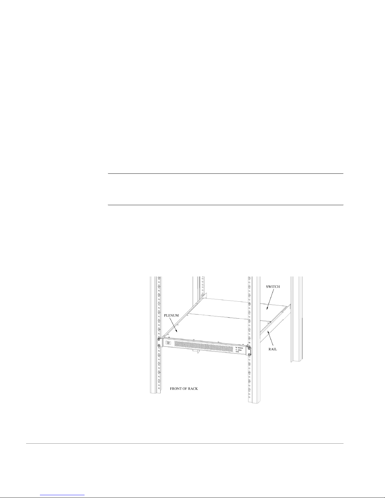
Installing the Switch in a Rack
This section provides instructions for installing the FC Entry Switch 8B or
FC Switch 8B in an HP or Compaq/Rittal rack.
Figure 1. FC Entry Switch 8B and FC Switch 8B Rack-Mounted Switch
4 Getting Started Guide
Page 11
The following items are required to install the switch in a rack:
• FC Entry Switch 8B or FC Switch 8B
• Power cable
• #2 Phillips and T25 Torx screwdrivers
•Plenum
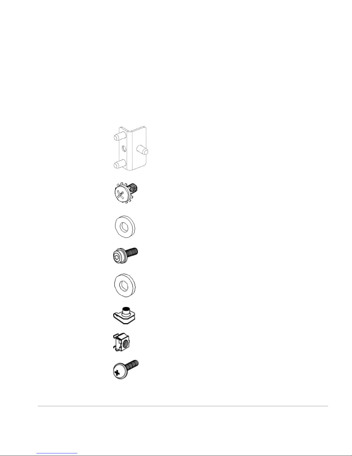
• Rails and rail mounting hardware:
(2) Rear mounting bracket
(8) #8-32 x 5/16 Phillips pan-head screw with captive star
lock wash er
(8) #8 Flat washer
(6) M5 Torx head screw with captive lock washer
(2) Rubber washer
(4) M5 U-type Tinnerman clip (HP rack only)
(4) #10-32 square Tinnerman nut (Compaq/Rittal rack only)
(4) #10-32 x 5/8 Phi ll ip s pan-head screw with attached lo ck
washer (Compaq/Rittal rack only)
Installing the Switch 5
Page 12

(6) Spacer (Compaq/Rittal rack only)
(4) M5 flat washer (Compaq/Rittal rack only)
CAUTION For proper airflow, the SFP media side of the FC Entry Switch
8B or FC Switch 8B faces the rear of the rack. This mounting allows air to
enter the front of the rack through the plenum and to exhaust at the rear of
the rack, s imilar to other rack-mou nted equipm ent. This pr events switch
overheatin g that may cause it to fail.
To install the switch in an HP rack:
1. Check contents of th e shipp ing carton to verif y all the r equired p arts and
hardware are available.
2. Choose a mounting location in the rack for the switch.
3. Attach the rear rail-tray brackets to the rear rack uprights by installing
each of the two mounting brackets with one M5 Torx head screw with
captive l ock washer as shown in Figure 2.
6 Getting Started Guide
Page 13
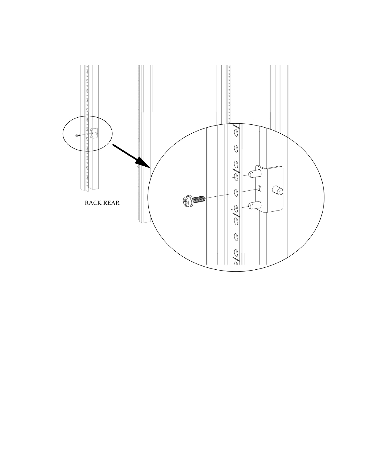
Figure 2. Installing the Rear Rail-Tray Brackets
4. Install two M5 U-type Tinnerman clips for each of the front columns of
the rack in the t op a nd bottom positions of the three-ho le EIA pattern as
shown in Figure 3.
Installing the Switch 7
Page 14
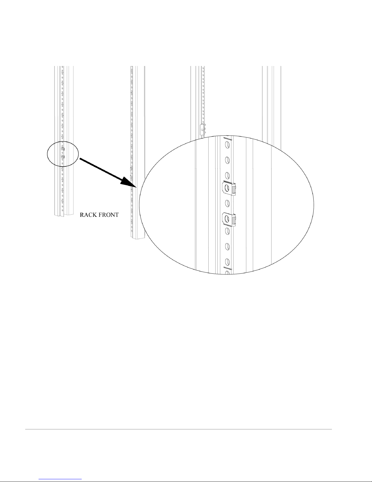
Figure 3. Installing the Tinnerman Clips
5. Assemble the outer rails by completing the followin g steps:
a. As an aid in asse mbly , two rub ber washers have been included to h elp
keep the rear slotted portion of the outer rail flush against the rear
rail-tray brackets. Install them as shown in Figure 4.
8 Getting Started Guide
Page 15
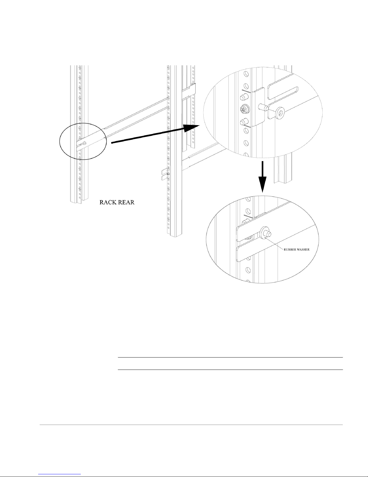
Figure 4. Installing the Rubber Washers
b. Insert the alignment pins attached to the outer rail front flange into the
center opening in the rack.
c. Install one M5 Torx screw in the upper hole location of the right rail.
Then, install one M5 T orx screw in the lower location of the left rail.
See Figure 5.
Note Do not install the upper left and lower right screws until later.
Installing the Switch 9
Page 16
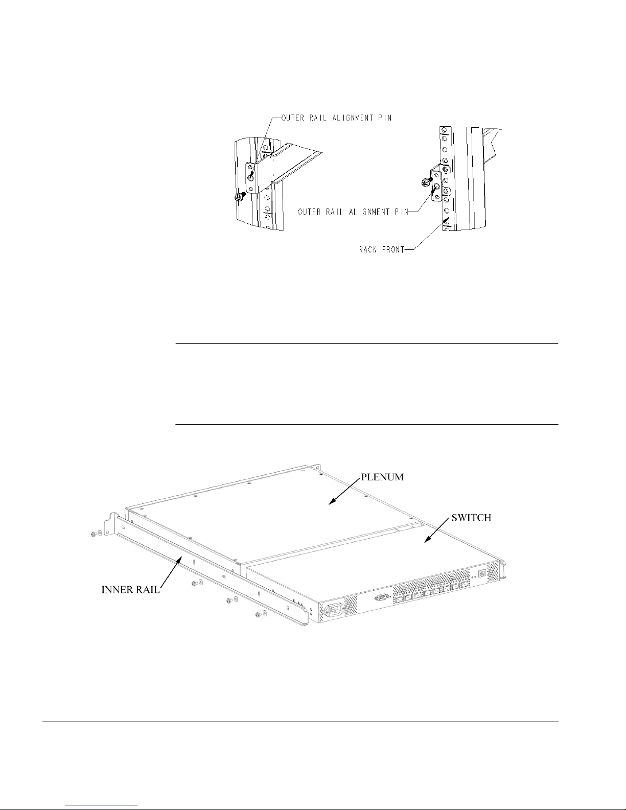
Figure 5. Assembling the Outer Rails
6. Assemble each of th e two i nne r rails (o ne on e ach si de of t he swi tch an d
plenum) using eight #8- 32 x 5/16 Phillips pan-head screws (wit h attached
star lock washers) and eight #8 flat washers as shown in Figure 6.
CAUTION Do not use any other screws other than the eight that are
provided. Use of any longer lengths can cause damage to internal
components of the switch. Be sur e t o install the flat washers along with the
pan-head screws. Before tightening screws, make sure that the rails are
centered to the overall height of the switch.
Figure 6. Assembling the Inner Rails
7. Insert the switch with the attached inne r rails into the out er rails as shown
in Figure 7.
10 Getting Started Guide
Page 17
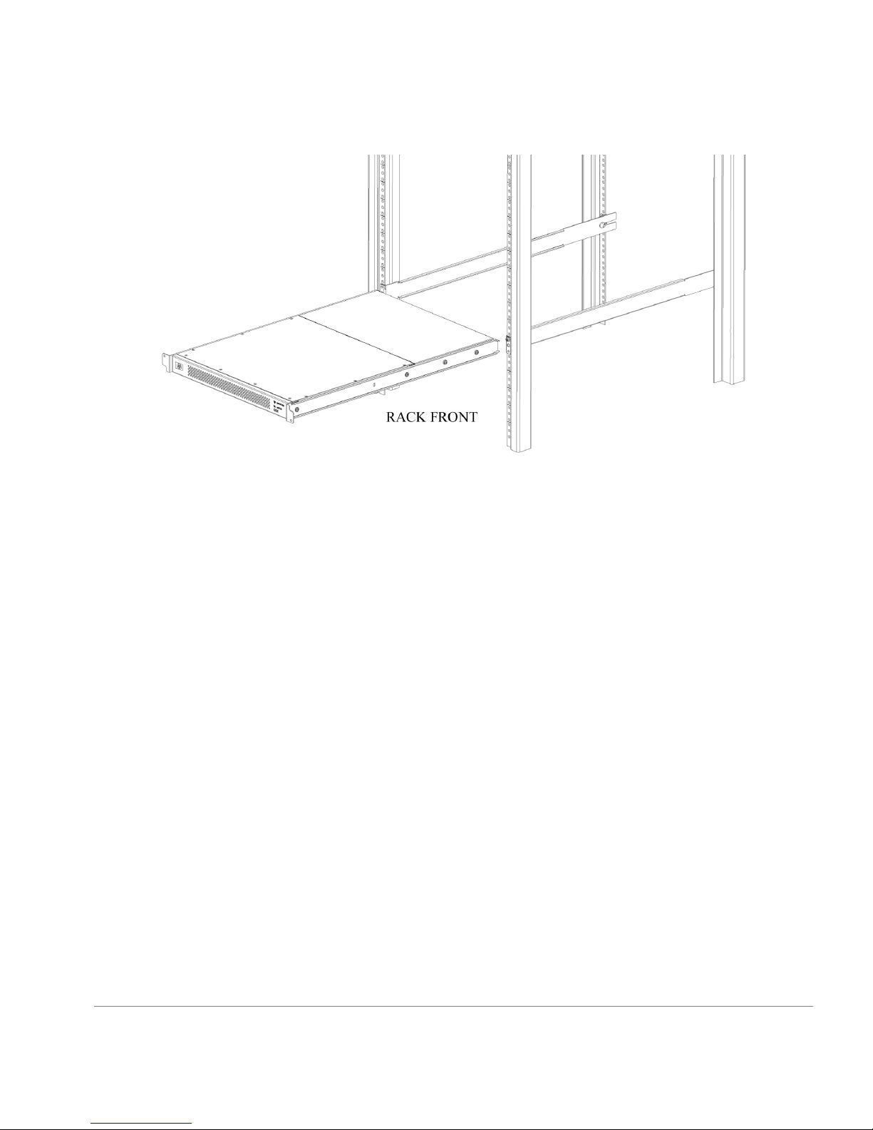
Figure 7. Installing the Switch into an HP Rack
8. Install the two remaining M5 Torx screws into the upper left and lower
right holes to complete the installation. See Figure 8.
Installing the Switch 11
Page 18
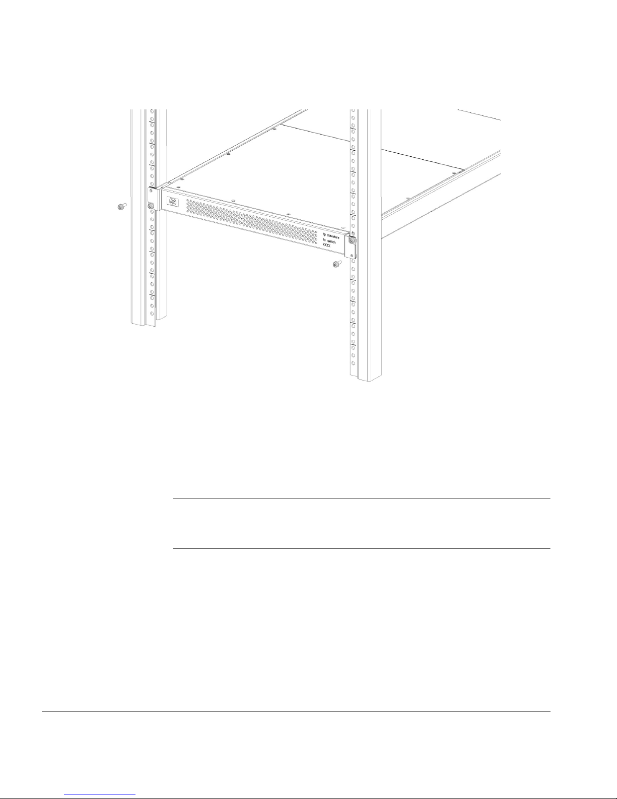
Figure 8. Securing the Switch
9. Provide power to the swit ch by connecting the power cord to the swi tc h
power supply and to a power outlet. Ensure the power cord is routed so
that it is not expose d to str ess. Power is supplied t o the switch a s soon as
the cord is connected. The switch runs POST (power on self-test) by
default each time it is turned on.
Note Do not connect the switch to the network until the IP address is
correctly set. For instructions on how to set the IP address, see
“Configuring and Connecting the Switch” on page 23.
To install the switch in a Compaq/Rittal rack:
1. Check contents of th e shipp ing carton to verif y all the r equired p arts and
hardware are available.
2. Choose a mounting location in the rack for the switch.
12 Getting Started Guide
Page 19

3. Attach the rear rai l-tr ay brack ets to t he re ar rac k uprigh ts by asse mbli ng
each of the two bracke ts with two spacers, t wo M5 flat wa shers, and o ne
M5 Torx head screw with captive lock washer as shown in Figure 9.
Note The alignment pins will be resting on the top surfaces of the spacers.
Figure 9. Installing the Rear Rail-Tray Brackets
4. Install two #10-32 square Tinnerman nuts for each of the front columns
Installing the Switch 13
of the rack in the top an d bottom posit ions of the three-hole EI A pattern.
Also install one spacer in the center position for each column on the front
of the rack. See Figure 10.
Page 20

Figure 10. Installing the Tinnerman Nuts and Spacers
5. Assemble the outer rails by completing the followin g steps:
a. As an aid in asse mbly , two rub ber washers have been included to h elp
keep the rear slotted portion of the outer rail flush against the rear
rail-tray brackets. Install them as shown in Figure 11.
14 Getting Started Guide
Page 21

Figure 11. Instal l ing the Rubber Washers
b. Insert the alignment pins attached to the outer rail front flange into the
center opening in the rack.
Note The alignment pins will be resting on the top surfaces of the spacers.
c. Install one #10-32 x 5/8 Phillips pan-head screw in the upper hole
location of the right rail. Then, install one #10-32 x 5/8 Phillips
pan-head screw in the lower locatio n of the left rail as shown in
Figure 12.
Note Do not install the upper left and lower right screws until later.
Installing the Switch 15
Page 22

Figure 12. Assembling the Outer Rack
6. Assemble each of th e two i nne r rails (o ne on e ach si de of t he swi tch an d
plenum) using eight #8- 32 x 5/16 Phillips pan-head screws (wit h attached
star lock washers) and eight #8 flat washers as shown in Figure 13.
CAUTION Do not use any other screws other than the eight that are
provided. Use of any longer lengths can cause damage to internal
components of the switch. Be sur e t o install the flat washers along with the
pan-head screws. Before tightening screws, make sure that the rails are
centered to the overall height of the switch.
16 Getting Started Guide
Page 23

Figure 13. Assembling the Inner Rails
7. Insert the switch with the attached inne r rails into the out er rails as shown
in Figure 14.
Figure 14. Installing the Switch into a Compaq/Rittal Rack
8. Install the re maining #10-32 x 5/8 Phillips pan-head screws into the upper
Installing the Switch 17
left and low er right holes to complete the installa tion. See Figure 15.
Page 24

Figure 15. Securing the Switch
9. Provide power to the swit ch by connecting the power cord to the swi tc h
power supply and to a power outlet. Ensure the power cord is routed so
that it is not expose d to str ess. Power is supplied t o the switch a s soon as
the cord is connected. The switch runs POST (power on self-test) by
default each time it is turned on.
Note Do not connect the switch to the network until the IP address is
correctly set. For instructions on how to set the IP address, see
“Configuring and Connecting the Switch” on page 23.
18 Getting Started Guide
Page 25

System Components
The FC Entry Switch 8B or FC Switch 8B consists of the following
components:
• A chassis designed to be mounted in a 1U rack space, w ith forced -air
cooling that flows fr om the fan side of the switch to the cable side.
• Eight optical ports, compatible with SFP (small form factor pluggable)
media.
• One RS-232 serial port (DB9 connector) on the SFP media side.
2
SETUP
• One IEEE compliant RJ-45 connector on the SFP media side for use
• Human-readable labels (including IP address label) and bar code labels
• A total of 20 LEDs:
with 10/100 Mbps Ethernet or in-band.
on the top of the switch.
– One LED on the SFP media side to indic at e the overall switch status.
– Two LEDs for each of the eight ports to indicate port status and link
speed information.
– Two LEDs for t he Ether net po rt to indi cate port s tatus and l ink s peed
information.
19
Page 26

SFP Media Side
– One LED in the center of the fan side to indicate the overall switch
status.
• One universal input power supply.
•Five fans:
– Two dedicated to cooling the power supply, three dedicated to
cooling the motherboard.
– Air is pulled in through the rear intake and pushed out through the
vents in the SFP media side.
• Three digital thermometers, capable of sensing a temperature range
from -55°C to +125°C, in 0.5°C increments.
• A real-time clock (RTC) with a 10-year battery and 56 bytes of
NVRAM.
Figure 16 shows the SFP media side of the switch, which contains the
power connector, IP label, serial port, switch status LED, fiber optic ports
and their corresponding LEDs, and the Ethernet port and its corresponding
LEDs.
Figure 16. The SFP Media Side of the FC Entry Switch 8B and FC Switch 8B
The switch ports are col or-coded into two groups of four, to indicate which
ports can be used in the same ISL Trunking group.
20 Getting Started Guide
Page 27

Fan Side
Note ISL Trunking is a Fabric OS feature that enables distribution of
traffic over the combined bandwidth of up to four ISLs between two
directly adjacent switches, while preserving in-order delivery. For
information about ISL Trunking, refer to the ISL Trunking User’s Guide.
Figure 17 shows the fan side of the switch, which contains the fa ns an d the
switch status LED.
Figure 17. The Fan Side of the FC Entry Switch 8B and FC Switch 8B
Power Supply
The power supply is universal and capable of functioning worldwide
without using voltage jumpers or switches. It meets IEC 61000-4-5 surge
voltage requirements and is autoranging in terms of accommodating input
voltages and line fre quencies. The power supply has its own built -in fan for
cooling, pushing the air towards the SFP media side of the switch. See
“Power Supply” on page 47 for a list of power supply specifications.
To turn the FC Entry Switch 8B or FC Switch 8B on, connect the power
cable to the power connector on the switch and to a power source. The
switch takes approximately 4.5 minutes to boot after it is turned on.
To turn the switch off, disconnect the power cable from the power source.
Setup 21
Page 28

Note Rem oving all power from th e switch tri ggers a system reset. When
power is restored, all devices are returned to the initial state and the switch
runs POST, a system check that lasts approximately 2.5 minutes.
POST can be skipped by using the fastboot command. For more
information abo ut thi s command, re fer to th e Fabric OS Refer enc e Manual.
A fast boot requires approximately two minutes to complete.
Fabric Operating System
Included with the switch is the Fabric OS. The system provides a large
number of commands and libraries to manage real-time tasks. See the
Fabric OS Reference Manual and the Fabric OS Procedures Guide for
details.
SFPs
The FC Entry Switch 8B or FC Switch 8B accommodates up to 8 SFPs
(small form factor pluggable media). The SFPs supported are the SWL
(short wavelength) and LWL (long wavelength) fibre-optics. Shortwave
SFPs have black dots visible from the fr ont. Longwave SFPs have blue dots
visible from the front. The SFPs qualified by HP are 1Gb/2Gb capable.
To install an SFP, position the SFP so that the key (the tab near the
cable-end of the SFP) is on top and insert the SFP into the port until it is
firmly seated and the latching mechanism clicks. For more specific
instructions, refer to the SFP manufacturer’s documentation.
Note The SFP is keyed so that it can only be inserted with the correct
orientation into the port. If the SFP does not slide in easily, ensure it is
correctly oriented.
Fibre Channel Cable Connections
LC cables are used to plug into SFPs. The cables required for the
HP/Brocade 2400 and 2800 switches have SC connectors and connect into
GBIC optic modules. LC to SC cables or adapters are required to connect
the cables together.
22 Getting Started Guide
Page 29

To connect an SC cable to the FC Entry Switch 8B or FC Switch 8B, use
the HP C7540A - 2M LC male - SC male cable adapter.
Connect inter switch links (ISLs) between two FC Entry Switch 8B or FC
Switch 8B products using an LC to LC cable.
Table 1. Cables Used with the FC Entry Switch 8B or FC Switch 8B
LC - SC Cable Connectors
Product
Number
Part
Number Description
C7534A 5183-2684 SC female - SC female adapter
C7540A N/A 2M LC male - SC male adapter kit -
contains both C7534A (adapter) and
C7529A (2 m eter cable)
C7529A 5065-5106 2m FC Cable LC-SC duplex M/M
C7530A 5065-5107 16m FC Cable LC-SC duplex M/M
LC - LC Cables
Product
Number
Part
Number Description
C7524A 5065-5101 2m FC Cable LC duplex M/M
C7525A 5065-5102 16m FC Cable LC duplex M/M
C7526A 5065-5103 50m FC Cable LC duplex M/M
C7527A 5065-5104 200m FC Cable LC duplex M/M
Configuring and Connecting the Switch
This procedure provides instructions for configuring and con necting the FC
Entry Switch 8B or FC Switch 8B for use in a network and fabric.
The following items are required to configure and connect the FC Entry
Switch 8B or FC Switch 8B:
• The FC Entry Switch 8B or FC Switch 8B installed and connected to a
Setup 23
power source
Page 30

• Workstation that has a terminal emula tor applica tion (such as
HyperTerminal)
• Serial cable provided with the switch for connecting the switch to the
workstation
• An unused IP address
• Ethernet cable for connecting the switch to the workstation or to a
network containing the workstation
• SFPs and FC cables as required to connect the switch to the fabric
To configure the switch and connect it to a fabric:
1. Replace the factory IP address and related inform ation with the IP
information provided by your network administrator by completing the
following steps:
a. Remove the shipping plug from the serial port and insert the serial
cable provided with the switch.
b. Connect the other end of the serial cable to an RS-232 serial port on
the workstation. If no RS-232 serial port is available on the
workstation, the ad apter on the end of the serial cable ca n be removed
to use the RJ-45 connector to create a serial connection.
c. V erify t hat the switch has power and POST is compl eted (LED display
has returned to a standard healthy state).
d. Disable any serial communication programs running on the
workstation.
e. Open a terminal emulator application (such as HyperTerminal on a
PC, or TERM in a Unix environment), and configure as follows:
– In a Windows 95, 98, 2000, or NT environment:
Parameter Value
Bits per second: 9600
Databits: 8
Parity: None
Stop bits: 1
Flow control: None
24 Getting Started Guide
Page 31

– In a UNIX environment, enter the following string at the prompt:
tip /dev/ttyb -9600.
f. From the terminal emulator application, lo g on to the switch with
administrative privileges through the serial connection. The default
administrative logon is admin and the default password is
password.
CAUTION Do not change the default password unless local administration
policy requires it.
g. Enter the following at the terminal emulator application prompt:
ipAddrSet.
h. Enter th e requested information at the prompts:
– Ethernet IP Address [10.77.77.77]:
Enter the new Etherne t IP address.
– Ethernet Subnetmask [0.0.0.0]:
Enter the new Ethernet subnetm ask.
– Fibre Channel IP Address [none]:
Enter the new Fibre Ch annel IP ad dress if des ired.
– Fibre Channel Subnetmask [none]:
Enter the new Fibre Channel subnet mask if de sired.
– Gateway Address [172.17.1.1]:
Enter the new gateway address.
– Set IP address now? [y = set now, n = next
reboot]:
Enter “y” to set now.
i. Optional: Verify the address was correctly set by entering the
following: ipAddrShow.
j. Record the IP address on the label provided for this purpose on the
switch.
k. Once the IP address is verified as correct, remove the serial cable and
replace the shipping plug in the serial port.
Setup 25
Page 32

Note The serial port is intended only for use during the initial setting of
the IP address and fo r serv ice pu rpo ses. Usi ng the seria l port duri ng normal
switch operation or for regular maintenance is not recommended.
2. Connect the switch to the workstation computer by Ethernet cable (can
be a direct connection or through a network).
a. Remove the shipping plug from the Ethernet port.
b. Insert one end of an Ethernet cable in the Ethernet port.
c. Connect the oth er end of the Ethernet cable to the workst ation (use a
cross-over Ethernet cable and the default IP address [10.77.77.77]
when connecting directl y to the workstation) or to an Ethe rnet network
containing the work station (us e a straight -through Ethe rnet cable a nd
the assigned IP address from Step 1 above).
Note The switch can now be accessed remotely, using telnet (although
only one telnet session can be active at a time) or Web Tools. Ensure that
the switch is not being modified from any other connections during the
remaining steps.
3. Log on to the switch with administrative privileges by telnet. The default
administrative logon is admin and the default password is password.
CAUTION Do not change the default password unless local administration
policy requires it.
4. Modify the domain IDs if desired by completing the following steps:
Note The default domain ID is 1. If the defau lt domain I D is alrea dy in use
when the switch is connected to the fabric, the domain ID for the new
switch is automatically reset to a unique value. The domain IDs that are
currently in use can be determined using the telnet command
fabricShow.
a. Disable the switch by entering the following: switchDisable.
26 Getting Started Guide
Page 33

b. Then enter the following to display the configuration prompts:
configure.
c. Enter “y” after the pr ompt “Fabric parameters”. For example:
Fabric parameters (yes, y, no, n): [no] y
d. Enter a unique domain ID: Domain: (1..239) [1] 3.
e. Complete the remaining prom pts or press CTRL+D to accept the
remaining settings without completing all the prompts.
f. Re-enable the swi t ch by entering the following: switchEnable.
5. Optional: Specify a ny custom status policies for the fabric by comple ting
the follow ing steps:
a. Enter th e following at the prompt: switchStatusPolicySet.
b. Customize the status pol icies as desired. T o comple tely deactivate the
alarm for a particular condition, enter “0” at the prompt for that
condition.
6. If necessary, install or change the SFPs (small form factor pluggable
media) by completing the following steps:
Note The ports selected for use in trunking groups must meet specific
requirements. For a list of these requirements, refer to the ISL Trunking
User’s Guide.
a. Remove the shipping plugs from the ports to be used.
b. Position the SFP so tha t the key (the tab near the cable-end of the SFP)
is on top and insert the SFP into the port until it is firmly seated and
the latching mechanism clicks. For instructions specific to the SFP
type, refer to the SFP manufacturer’s documentation.
Note The SFP is keyed so that it can only be inserted with the correct
orientation into the port. If the SFP does not slide in easily, ensure it is
correctly oriented.
7. Connect the cables to the SFPs as appropriate to the fabric topology.
Position each cable so that the key (the ridge on one side of the cable
connector) is align ed with the slot in the SFP. Then, insert the cable into
Setup 27
Page 34

the SFP un til it is firml y seated and the latchi ng mechanism clicks. For
instructions specific to the cable type, refer to the cable manufacturer’s
documentation.
Note The cables used in trunking groups must meet specific re quirements .
For a list of these requiremen ts , refer to the ISL Trunking User’s Guide.
The cable is keyed so that it can only be inserted correctly into the SFP. If
the cable does not slide in easily, ensure it is correctly oriented.
8. Optional: Verify the correct operation of the switch by entering the
following command from a workstatio n: switchShow. This command
provides informat ion about the status of t he switch and the ports. For more
information about this and other commands, refer to the Fabric OS
Procedures Guide.
Use the cfgSave and cfgEnable commands to save any zone
configurations before the switch is powered off. The saved
configuration is automatically reloaded by the switch on power up. If a
configuration was enabled at the time it was saved, the same
configuration is reinstalled with an automati c cfgEnable command.
Saving the System Configuration Files
Upload the switch configuration file for disaster recovery and keep it in a
safe place where it can be easily found. Backing up the configuration after
the initial configuration changes and periodically thereafter is strongly
recommended.
Backing up the Switch Configuration Settings
FTP must be used on Windows workstations to backup the system
configuration. The FTP server must be r unning be fore a n upload can o ccur.
Use the RSHD service or FTP on a UNIX machine.
Note The two supplied utilities, RSHD.EX E and CAT.EXE currently do
not support uploads for Windows, only downloads. These utilities are
available from the support Web site: http://www.hp.com/support/fc8B.
28 Getting Started Guide
Page 35

1. Verify that the RSHD service (on a UNIX machine) or the FTP service
(on a Windows machine) is running on the host workstation.
2. Log on to the switch as the admin user.
3. At the command line enter the following command:
configUpload "hostIPaddr", "user",
"path_filename","password"
where hostIPaddr is th e IP address of the host computer, user is the
User ID used to log into t his computer,
location and filename of the configuration file, and
password for the user ID specified. If only
path_filename is the path
password is the
configUpload is entered
the system prompts you for each parameter.
Example:
switch:admin> configupload
Server Name or IP Address [host]: 123.45.678.901
User Name [user]: kelev
File Name [config.txt]: switch1
Protocol (RSHD or FTP) [rshd]: ftp
Password:
upload complete
Restoring the System Configuration Settings
To restore the system configuration settings from a backup:
1. Verify that the RSHD service or the FTP service is runni ng on the hos t
workstation (Windows or UNIX).
2. Login to the switch as the admin user.
3. Shut down the switch by entering the following command:
switchDisable
4. At the command line enter the following command:
configDownload "hostIPaddr", "user",
"path_filename","password"
where hostIPaddr is the IP address of the host computer containing
the configuration file,
computer,
Setup 29
path_filename is the path location and filename of the
user is the User ID used to log into this
Page 36

system configuration f ile, and password is the password for the user ID
specified.
Note The password operand is only required if you are using FTP.
5. Reboot the switch by entering the following command:
fastBoot
Next Steps
Specific tasks re main to be com plet ed befo re th e swit ch is f ully op era tiona l
and manageable in your network with your equipment. These tasks and the
associated tools are descri bed in t he remai ning doc uments sh ipped wit h the
product on the Document ation CD. This sect ion provid es spec ific guidanc e
for completing tasks that many users may need to do.
Setting QuickLoop Mode on Ports
The default configuration for a port is fabric mode. QuickLoop is used to
connect private host s to private storage usi ng the Fibre Chann el network. A
QuickLoop zone, connecting two switches, may be used to expand the
number of private hosts and stora ge connected. An entire switch can be set
to operate in QuickLoop mode using the
port on a switch operating in Mixed mode can be set to or removed from
QuickLoop using the telnet commands
qlPortDisable. See the QuickLoop User’s Guide for more de tails.
qlEnable telnet co mmand. A
qlPortEnable and
Setting Up Speed Negotiation
There are two methods for confi guring t he ports o n the FC Entr y Switch 8B
and FC Switch 8B. The po rt can be set to auto-sensing mode, whi ch al lows
the port to automatically be configured to the highest speed. Ports can also
be set to a fixed speed of either 1 or 2 Gbps.
To display the configuration settings of the ports on a switch, use the
portCfgShow. The port speed is displayed as 1G (f ixed speed of 1
Gbps), 2G ( fi xed speed of 2 Gbps), or AN ( auto-n egoti ate). To set the speed
level for all the ports on a switch, use the telnet command
30 Getting Started Guide
Page 37

switchCfgSpeed. To set the speed level for a single port, use the
portCfgSpeed.
Depending on your environment you may need to force a port to use a
specific speed level. Auto negotiation may not be supported by the device.
Check the configuration information for your network components for
specific requirements. See the Fabric OS Reference Manual for a detailed
command description.
Configuring Supported Devices
HP Surestore Director FC-64 Switch
The FC Entry Switch 8B or FC Switch 8B switch can be used with the HP
Surestore Director FC-64 switch. Specific configurations must be set on
both devices to make this work.
On the FC Entry Switch 8B or FC Switch 8B, log on to the switch with
administrative privileges and enter the following telnet commands:
1. switchDisable
2. interopMode 1
3. switchEnable
On the Dire ctor FC-64 switch, the following steps must be completed to
configure the switch f or interoperability:
Step 1: Verify Unique Domain IDs
Step 2: Select a Single Surestore FC-64 Director as Principal Switch
Step 3: Verify Unique Zone Names
Step 4: Verify Brocade Product Zoning Configurations
Step 5: Verify Zone Naming Conventions
Step 6: Verify Operating Mode
Step 7: Verify Surestore FC-64 Director Switches’ Operating
Parameters
Step 8: Verify Firmware Versi on
Step 9: Verify EFC Manager Version
Step 10: Verify Private Loop Targets on Brocade Products are
Translated to Fabric
Step 11: Add Switches to Fabric
Setup 31
Page 38

Step 12: Complete Zoning Activities
Step 13: Save Active Zone Set
For complete inst ructi ons on con figuring the HP Dir ector FC-64 s witch see
“Checklist for Merging Fabrics” in the Merging Heterogeneous Fabrics
Instructions white paper on the FC Entry Switch 8B or FC Switch 8B
Documentation CD.
HP Surestore VA 7400
The FC Entry Switch 8B or FC Switch 8B also can support a 2Gb
connection to an HP Surestore Virtual Array 7400. Set the port speed to
2Gb using the telnet command
portCfgSpeed.
Use the V i rtual Fr ont Panel ( VFP) on the VA 7400 and configure the de vice
as follows:
1. Change the controller port data rate to 2 Gbits/s
a. T o change the port data rate to 2 gigabi ts/second for contro ller 1, enter:
vfpmgr -S 2 -c 1
When prompted to reset, enter no.
b. To change the port data rate for controller 2, enter:
vfpmgr -S 2 -c 2
When prompted to reset, enter no if additional settings must be
changed. If all changes have been made, enter
yes to reset the array.
2. Change the controller port topology.
a. To change the port topology for controller 1 enter the following
command, selecting
vfpmgr -t 4 -c 1
4 for Direct Fabric Attach:
When prompted to reset, enter no.
b. To change the port topology for controller 2 enter the following
command, using the same topology value used for controller 1:
vfpmgr -t 4 -c 2
When prompted to reset, enter no if additional settings must be
changed. If all changes have been made, enter
yes to reset the array.
32 Getting Started Guide
Page 39

Private Loop Devices
To work with private loop devices such as the FC 60, the FC 10, or the
SCSI bridge FC 4/2, set th e FC Entry Switch 8 B or FC Swit ch 8B por t as an
L_PORT. See the telnet command
portCfgLport.
Setup 33
Page 40

34 Getting Started Guide
Page 41

Switch Status Indicators
System activity and status can be determined through the activity of the
LEDs on the switch .
Note The LEDs may flash yellow during diagnostic tests, and green,
yellow, or orange during POST. This is normal, and does not indicate a
problem unless the LEDs do not display a he althy patt ern after POST or t he
other diagnostic tests are complete.
3
DIAGNOSTICS
The orange light may be referred to as “amber” in other documentation.
The switch includes the following LEDs:
• Eight port status LEDs on the SFP media side (above and to the left of
• Eight port speed LEDs on t he SFP media side (above and to the right o f
• One switch status LED on the SFP media side and one on the fan side,
each port) to indicate the status of each port.
each port) to indicate the current link speed of each port.
to indicate whether the switch is on and has successfully booted, and
whether any of the ports are faulty.
35
Page 42

• Two Ethernet port LEDs, one to show link speed and one to show link
status.
LEDs on the SFP Media Side
Figure 18 shows the SFP media side of the swit ch with the LEDs id entifie d.
Figure 18. The SFP Media Side of the FC Entry Switch 8B and FC Switch 8B
Note The LEDs may flash different colors during diagnostic tests and
POST. This does not indicate a problem unless the LEDs do not display a
healthy pattern after POST or the other diagnostic tests are complete.
The following table describes the switch status LED located to the right of
the serial port on the SFP media side of the switch.
Color of LED Status of Hardware Recommended Action
No light Either the switch is off, or boot
is not complete, or boot has
failed.
Verify that the switch
is on and boot has had
time to complete. If
there is still no light,
contact HP support.
Steady green Switch is on and all ports are
No action required.
ready for use.
36 Getting Started Guide
Page 43

Color of LED Status of Hardware Recommended Action
Steady yellow One or more ports are not ready
for use. Switch may be booting
or disabled, or one or more
ports may be faulty.
Verify that the switch
has completed
booting and is not
disabled. If the light
is still yellow, check
the port status LEDs.
Slow-flashing
yellow
One or more ports are faulty. Check the port status
LEDs. Also, any
errors are listed in the
error log. For more
information about t he
error log, refer to the
Fabric OS
Procedures Guide.
The following ta bl e de scr ib es t h e por t s tat us LEDs located above each port
on the left.
Color of LED Status of Hardware Recommended Action
No light No light or signal carrier
(media or cable) is detected.
Steady green Port is online (connected to an
external device) but has no
traffic.
Slow-flashing
green (on 1
second; off 1
Port is online but segmented,
indicating a loopback cable or
incompatible switc h.
second)
Fast-flashing
green (on 1/4
The port is in intern al loopba ck
(diagnostic).
second; off 1/4
second)
Verify that media and
cable are both firmly
seated an d functiona l.
No action required.
Verify correct device
is connected to port.
No action required.
Diagnostics 37
Page 44

Color of LED Status of Hardware Recommended Action
Flickering green Port is online, with traffic
No action required.
flowing through port.
Steady orange Port is receiving light or signal
No action required.
carrier, but is not yet online.
Slow-flashing
orange (on 1
second; off 1
The port is disabled
(result of diagnostics or
portDisable command).
Reset the port from a
management station.
second)
Fast-flashing
orange (on 1/4
second; off 1/4
The port is faulty. Reset the switch from
a management
station.
second)
Alternating green
and yellow
Port is bypassed. Reset the port from a
management station.
The following ta bl e de scr ib es the port speed LEDs located above each port
on the right.
Color of LED Status of Hardware Recommended Action
No light The port is
No action required.
transmitting/receiving at
1 Gbps.
Steady green The port is
No action required.
transmitting/receiving at
2 Gbps.
No light The port is
No action required.
transmitting/receiving at
10 Mbps.
Steady green The port is
No action required.
transmitting/receiving at
100 Mbps.
38 Getting Started Guide
Page 45

Color of LED Status of Hardware Recommended Action
No light No Ethernet traffic is flowing
Steady green Ethernet traffic is flowing
LEDs on the Fan Side
Figure 19 shows the fan side of the switch with the LED identified.
through the RJ-45 port.
through the RJ-45 port.
Verify that the switch
has power and the
Ethernet cable is
firmly seated.
No action required.
Figure 19. The Fan Side of the FC Entry Switch 8B and FC Switch 8B
Note The LEDs may flash different colors during diagnostic tests and
POST. This does not indicate a problem unless the LEDs do not display a
healthy pattern after POST or the other diagnostic tests are complete.
Diagnostics 39
Page 46

The following table describes the switch status LED on the fan side of the
switch.
Color of LED Status of Hardware Recommended Action
No light Either the switch is off, or boot
is not complete, or boot has
failed.
Steady green Switch is on and all ports are
ready for use.
Steady yellow One or more ports are not rea dy
for use. Switch may be booting
or disabled, or one or more
ports may be faulty.
Slow-flashing
One or more ports are faulty. Check the port status
yellow
Verify that the switch
is on and boot has had
time to complete. If
there is still no light,
contact HP support.
No action required.
Verify that the switch
has completed
booting and is not
disabled. If the light
is still yellow, check
the port status LEDs.
LEDs. Also, any
errors are listed in the
error log. For more
information about t he
error log, refer to the
Fabric OS
Procedures Guide.
Maintenance and Diagnostic Tests
Neither the FC Entry Switch 8B nor FC Switch 8B requires any regular
physical maintenance and is designed to minimize the chance of failure.
Diagnostic tests are provided to help troubleshoot the hardware and the
firmware. The diagnostic tests provided on the switch include tests of
internal connections and circuitry, fixed media, and any SFP modules and
fiber optic cables in use. The tests are implemented by command, either
through a telnet session or thr ough a terminal set up for a serial connection
to the switch. Some tests require the ports to be connected by external
40 Getting Started Guide
Page 47

cables, to al low dia gnostics to verify the seri ali ze r/ deserializer interface, as
well as the attached SFP and cable.
All diagnostic tests are run at link speeds of both 1 Gbps and 2 Gbps. For
detailed information about the specific diagnostic tests and how to run
them, refer to the Fab ric OS Procedures Gu ide.
Note The transmit and receive speed of the links may be temporarily
locked to a specific speed during diagnostic testing.
Test Command Description
Error Log errDump Displays the error log without
page breaks.
Switch Offline switchDisable Sets the switch to offline state
necessary to run certain switch
diagnostics.
Memory Test ramTest Checks CPU RAM memory. Run
offline or online.
Port Register
Test
Central Memo ry
Test
Control Message
Interface (CMI)
Conn Test
Content
Addressable
Memory (C AM)
Test
portRegTest Checks that the registers and stat ic
memory in each ASIC can be
successfully accessed. Run
offline.
centralMemoryTest Checks that the c entral me mory in
each ASIC can be successfully
accessed. Run offline.
cmiTest Verifies that control mess age s c an
be sent from ASIC to ASIC.
Run offline.
camTest Verifies CAM functionality. Run
offline.
Diagnostics 41
Page 48

Test Command Description
Port Loopback
Test
portLoopbackTest Checks all switch main board
hardware. Frames transmitted are
looped back and received. Run
offline.
Cross Port Test crossPortTest Checks all switch paths. Frames
transmitted by port M are looped
back via external cable and
received at port N. Run offline or
online.
Spin Silk Test spinSilk Checks all switch paths at the
maximum speed of 1 Gbps.
Frames transmitted by port M are
looped back via external cables
and when received by port N are
sent again by port M in an
external loop. Run offline.
SRAM Data
Retention Test
sramRetentionTest Verifies that data written into
ASIC memories is retained. Runs
offline.
CMem Data
Retention Test
CmemRetentionTest Verifies that data written into
ASIC SRAMs is retained. Runs
offline.
Switch Online switchEnable Returns switch to online state.
Error Messages
To analyze error messages, access the error message log via a Telnet
session using the
power from the switch; error messages are stored in RAM and are lost
when power is removed. See the Fabric OS Reference Manual for a
detailed description of each message.
42 Getting Started Guide
errDump command. Note any messages befor e removi ng
Page 49

Getting Support
Service and Support
There are no customer servicea ble parts in the FC Entr y Switch 8B or FC
Switch 8B. For the most current technical support information for the FC
Entry Switch 8B and FC Switch 8B, visit the HP Web site at
http://www.hp.com/support/fc8B.
Additional Licenses
For information on obtaining license keys visit the HP Web site at
http://www.hp.com/support/fc8B.
Diagnostics 43
Page 50

44 Getting Started Guide
Page 51

General
4
SPECIFICATIONS
The following ta bl e l is ts the general specifications f or t he FC Entry Switch
8B and FC Switch 8B.
Specification Description
Fabric
initialization
IP over Fibre
Channel
(FC-IP)
System
architecture
System
processor
Number o f
Fibre Channel
ports
Fibre Channel
port speed
Complies with FC-SW 5.0
Complies with FC-IP 2.3 of the FCA profile
Non-blocking shared-memory switch
Intel 80960VH, 100MHz CPU
8 SFP ports
1 or 2 Gbps, full duplex
45
Page 52

Specification Description
Modes of
Fibre Channel Class 2 and Class 3
operation
Aggregate
32 Gbps if all 8 ports running at 2 Gbps, full duplex
switch I/O
bandwidth
Frame buffers 27 buffers per E_Port and 16 buffers per F_Port at 2112
bytes per frame
Port to port
latency
Data
transmission
range
Less than 2 microseconds with no contention (destination
port is free)
With 50 u cable at 2 Gbps:
Up to 300 m (984 ft.) for short-wavelength optical link
Up to 10 km (6.2 mi.) for long-wavelength optical link
With 62.5 u cable at 2 Gbps:
Up to 150 m (492 ft.) for short-wavelength optical link
Up to 10 km (6.2 mi.) for long-wavelength optical link
Chassis type Forced-air cooling that fl ows from the fan side to the SFP
media side
Environmental
The following table lists the acceptable environmental ranges.
Condition Acceptable Range
Temperature (operating) 10°C to 40°C
Temperature (non-operating) -35°C to 65°C
Humidity (operating) 20% to 85% RH non-condensing, at 40° C
Humidity (non-operating) 85% RH non-conducting, at 70°C
Altitude (operating) 0 to 3 kilometers above sea level
Altitude (non-operating) 0 to 12 kilometers above sea level
Shock (operating) 4 G, 11 MS duration, half sine
46 Getting Started Guide
Page 53

Dimensions
Condition Acceptable Range
Shock (non-operating) 20 G, 11 MS duration, sq. wave
Vibration (operating) 5 G, 0-3 kHz at 1.0 octave/minute
Vibration (non-operating) 10 G, 0-5 kHz at 1.0 octave/minute
The following table li sts t he dimensi ons of th e FC Entry Swit ch 8B and FC
Switch 8B.
Dimension Value
Height 1.69 inches (4.2 cm)
Depth 10.4 inches (26.4 cm)
Width 16.9 inches (42.8 cm)
Weight 8.0 lbs (3.6 kg)
Power Supply
The following table lists the power supply specifications.
Specification Value
Maximum output 75 watts
Maximum system power
50 watts
consumption
Input voltage 90 - 264 VAC
Input line frequency 47 - 63 Hz
Harmonic distortion Active power factor correction per
IEC1000-3-2
BTU rating 60 Watts x 3.412 BTU/Hr /Watts = 204.72
BTU/hr
Specifications 47
Page 54

48 Getting Started Guide
Page 55

PRODUCT REGULATORY INFORMATION
FCC EMC Statement (USA)
This equipment has been tested and found to comply with the limits for a Class A
digital device, pursuant to Part 15 of the FCC Rules. These limits are designed to
provide reasonable protection against harmful interference when the equipment is
operated in a commercial environment. This equipment generates, uses and can
radiate radio frequency ener gy and, if n ot installed an d used in accordance with the
instruction manual, may cause harmful interference to radio communications.
Operation of this equipment in a residential area is likely to cause harmful
interference, in which case the user will be required to correct the interference at
his own expense. The end u ser of this pro duct sho uld be aware that any changes or
modifications made to this equipment without the approval of Hewlett-Packard
could result in the product not meeting the Class A limits, in which case the FC C
could void the user's authority to operate the equipment.
EMC Statement (Canada)
This Class A digital apparatus meets all requirements of the Canadian
Interference-Causing Equipment Regulations.
Cet appareil numérique de la Classe A respecte toutes les exigences du Règlement
sur le matériel brouilleur du Canada.
EMC Statement (European Union)
This is a Class A product. In a domestic environment this product may cause r a dio
interference, in which case the user may be required to take adequate measures.
Spécification ATI Classe A (France)
DECLARATION D'INSTALLATION ET DE MISE EN EXPLOITATION d'un
matériel de traitement de l'information (ATI), classé A en fonction des niveaux de
perturbations radioélectriques émis, définis dans la norme européenne EN 55022
concernant la Compatibilité Electromagnétique.
49
Page 56

Germany Noise Declaration
Schalldruckpegel Lp = 46.1 dB(A)
Am Arbeitsplatz (op erator position)
Normaler Betrieb (normal operation)
Nach ISO 7779:1999 (Typprüfung)
VCCI EMC Statement (Japan)
Harmonics Conformance (Japan)
BSMI EMC Statement (Taiwan)
RRL EMC Statement (Korea)
50 Getting Started Guide
Page 57

Laser Safety
A. Certification and Classification Information
When equipped with native Fibre Channel adapters, this product contains a laser
internal to the small form factor pluggable (SFP) transceiver modules.
In the USA, the SFP module is certified as a Class 1 Laser product, conforming to
the requirements contained in Department Of Health and Human Services (DHHS)
regulation 21 CFR, Subchapter J. The certification is indicated by a label on the
metal SFP housing.
Outside the USA, the SFP is certified as a Class 1 Laser product conform ing to
requirements contained in IEC 825-1:1993 and EN60825-1:1994, including
Amendment 11:1 996 .
The SFP includes the following certifications:
• UL Recognized Component (USA)
• CSA Certified Component (Canada)
• TUV Certified Component (European Union)
• CB Certificate (Worldwide)
The following figure shows the Class 1 information label that appears on the metal
housing of the SFP.
CLASS 1 LASER PRODUCT 21 CFR(J)
B. Product Information
Each communications port consists of a transmitter and receiver optical
subassembly. The transmitter subassembly contains internally a semiconductor
laser diode in the wavelength of either 850 nanometers (shortwave laser) or 1310
nanometers (longw ave laser).
Class 1 Laser products are not considered hazardous.
WARNING There are no user maintenance operations, service operations, or
adjustments to be performed on the SFP module.
C. Usage Restrictions
Failure to comply with these usage restrictions may result in incorrect operation of
the system and points of access may emit laser radiation above the Class 1 limits
established by the IEC and U.S. DHHS.
Product Regulatory Information 51
Page 58

Declaration of Conformity
Manufacturer's Name:
Network Storage Solutions Organization
Manufacturer's Address:
Roseville, CA 95747
USA
declares, that the product
Product Name:
Model Number(s):
Product Options:
conforms to the following Product Specifications:
Safety: IEC 60950:1991 + A1, A2, A3, A4 / EN 60950:1992 + A1, A2, A3, A4, A11
GB 4943-1995
IEC 60825-1:1993 / EN 60825-1:1994 + A11, Class 1 (Laser/LED)
EMC: CISPR 22:1997 / EN 55022:1998 Class A
CISPR 24:1997 / EN 55024:1998
IEC 61000-3-2:1995 / EN 61000-3-2:1995 +A14
IEC 61000-3-3:1994 / EN 61000-3-3:1995
A7346A, A7346AZ, A7347A, A7347AZ
All
GB 9254-1988
DECLARATION OF CONFORMITY
accordin g to ISO/ IEC Gui de 22 and EN 4501 4
Hewlett-Packard Company
8000 Foothills Blvd.
hp surestore fc 1Gb/2Gb entry switch 8B
hp surestore fc 1Gb/2Gb switch
8B
1
Supplementary Information
The product herewith complies with the requirements of the Low Voltage Directive 73/23/EEC
and the EMC Directive 89/336/EEC and carries the CE marking accordingly.
1) The Product was tested in a worst-case test configuration which maximizes RFI emissions.
Roseville, CA
October 15, 2001
European Contact: You r local Hewlett-Pac kard Sales and Servic e Office or Hewlett-Pac kard GmbH, Departm ent HQTRE, Herrenberger Straße 130, D-71034 Böblingen (FAX: + 49-7031-14-3143)
:
52 Getting Started Guide
Page 59

Page 60

Technical information in this document
is subject to change without notice.
© Copyright Hewlett-Packard Company 2001.
All right reserved.
Reproduction, adaptation, or translation
without prior written permission is pro hibited
except as allowed under the copyright laws.
Printed in U.S.A.
E1201
Manual Part Number
A7346-96002
*A7346-96002*
 Loading...