

Page 1

Site Prep Guide
HP SureStore E Disk Array XP512
Page 2

Notice
Safety notices
© 2000, Hewlett-Packard Company.
Order number A5951-90915
E0800 A5951-96150
Hewlett-Packard Company makes no warranty of any
kind with regard to this material, including, but not
limited to, the implied warranties of merchantability and
fitness for a particular purpose. Hewlett-Packard shall not
be liable for errors contained herein or for incidental or
consequential damage s in c o nn ectio n with the fu rnish in g,
performance, or use of this material.
This document conta in s p rop rie tar y info rm at ion , whic h is
protected by co pyright. No part of t his document may be
photocopied, reproduced, or translated into another
language without the prior written consent of HewlettPackard. The inform ation contained in this document is
subject to change without notice.
Warranty
Any servicing, adjustment, maintenance, or repair that
must be performed only by authorized service-trained
personnel.
Caution
WARNING
Denotes a hazard that can cause
hardware or software damage.
Denotes a hazard that can cause
personal injury or death.
If you have any qu es ti ons about the warran ty f or this
product, contact your dealer or local HP sales
representative.
Trademarks
Windows NT, Microsoft, Windows, MS Windows, and
MS-DOS are U.S. registered tra demarks of Microsoft
Corporation.
Other reserved names are trademarks of the respective
companies.
2
Page 3

Revision History 7
Updates 8
1 Introduction 9
2 The Site Prep Team and Tasks 11
The Site Prep Team 12
The HP Sales Representative (SR) 12
The HP Customer Engineer (CE) 12
The HP Application Software Engineer (ASE) 12
The Customer 13
Site Prep Technical Tasks 14
Site Planning Timetable 16
CONTENTS
3 Preparing for Installation 17
Safety Requirements 18
General Computer Room Requirements 19
Site Safety Consideration 18
Fire Safety 18
Equipment Servicing Hazards 18
Space planning 19
The HP SureStore E Disk Array XP512 20
3
Page 4

Physical Requirements 21
Dimensions 21
HP SureStore E Disk Array XP512 Weight 23
Specific Component Dimensions And Weights 23
Service and Cable Routing Space Requirements 27
Data Comm Requirements 38
Phone Home With Continuous Track 38
Local Area Network (LAN) 39
Outside Phone Line 40
Electrical Requirements 41
Line Voltage 41
Branch Circuit Breakers 41
Frequency 42
AC Line Voltage Requirements for the HP SureStore E Disk Array
XP512 42
Safety and Dedicated Ground 44
HP SureStore E Disk Array XP512 Grounding Requirements 44
Receptacles 45
Power Line Transients 45
Maximum Peak Inrush and Crest Factor 46
Sources of Electrical Interference 47
3-Phase AC Cabling for USA 49
Connecting the External Power Supply Cord 49
Branch Circuit Requirements 49
3-Phase AC Cabling for Europe 51
Connecting the Power Supply Cord 51
Branch Circuit Requirements 52
Single-Phase AC Cabling for USA 53
Connecting the Power Supply Cord 53
Branch Circuit Requirements 55
Single-Phase Cabling for Europe 56
Connecting the Power Supply Cord 56
Branch Circuit Requirements 57
4
HP SureStore E Disk Array XP512: Site Prep Guide
Page 5

Uninterruptible Pow er Supply (UPS) 58
UPS Features 58
UPS Limitations 58
Power Requirements: Single Secondary Input (Primary Offline) 59
Reference Supplier Information 59
Environmental Requirements 60
Air Conditioning Ducts 60
Humidity 60
Dust and Pollution Control 61
HP SureStore E Disk Array XP512 Temperature and Humidity
Specifications 61
Heat Dissipation 64
Altitude 65
Acoustics 66
Delivery Space Requirements 67
4 Upon Receipt of Your HP SureStore E Disk Array
XP512 69
Checking for Shipping Shortage and Damage 70
Unpacking the Cartons 71
Contents
Index 73
5
Page 6

6
HP SureStore E Disk Array XP512: Site Prep Guide
Page 7

Revision History
11 July 2000 First release.
23August 2000 Second release; fill ed in some mi ssing va lues on t he
weight table (Chapter 3)
Revision History
7
Page 8

Updates
For the most current information about HP SureStore E XP products, visit
the support web site:
www.hp.com/support/xp512
For information about product availa bili ty, co nfigur atio n, and connec tivi ty,
consult your HP account representative.
8
HP SureStore E Disk Array XP512: Site Prep Guide
Page 9

1
INTRODUCTION
The objective of a site prep is to prepare your site for the successful and
timely installation of your HP SureStore E Disk Array XP512. Proper site
preparation and maintenance is vital to the reliability of your HP SureStore
E Disk Array XP512. A site prep is a delicate balance of equipment design
criteria, site env ironmen tal va riabl es, your busine ss need s, a nd your bu dget
constraints. This guide contains site preparation information for the HP
SureStore E Disk Array XP512. Other site preparation resources may also
be available to you. Consul t with your HP repre sentati ve specializi ng in the
HP SureStore E Disk Array XP512.
The contents of this manual are arranged as follows:
Chapter 1 This introduction chapter.
Chapter 2 Introduction to HP’s service organization and site
Chapter 3 Site preparation and planning information specific to
Chapter 4 Information on the receipt of your HP Sure S tore E Disk
planning services. It also outlines your responsibilities
and the responsibiliti es of HP service personnel.
the HP SureStore E Disk Array XP512.
Array XP512.
9
Page 10

10
HP SureStore E Disk Array XP512: Site Prep Guide
Page 11

2
THE SITE PREP TEAM AND TASKS
The HP service organization is committed to making sure you receive the
maximum benefits of your HP SureStore E Disk Array XP512. Brief
descriptions of the HP team and how they can assist you are inclu ded in this
chapter. You are also an integral part of the site prep team. Your
responsibilities are al so descri bed here. The table on pa ge 14 provi des a site
inspection checklist and includes a reference for pertinent information.
11
Page 12

The Site Prep Team
The site prep pl anning team i s res ponsib le fo r det ermini ng sit e loc ation and
location size, ensuring that construction requirements and local codes are
met, and scheduling all events related to site co mpletion to prepare for the
successful installation and maintenance of the HP SureStore E Disk Array
XP512. The site prep team consists of the following personnel:
• sales representative
• customer engineer
• application software engineer
•customer
The HP Sales Representative (SR)
The sales representative is your primary point of contact. A sales rep
coordinates all the HP resources to ensure successful delivery and
installation of your disk array.
The HP Customer Engineer (CE)
The HP CE is train ed and experienced in the installation of your disk array.
They have the tools, part s, and knowledge to install and maintain your HP
SureStore E Disk Array XP512. The CE will also assist you in determining
your site prep requirements.
The HP Application Software Engineer (ASE)
The HP ASE is a software technical specialist trained in configuring your
HP SureStore E Disk Array XP512. The ASE can install and configure all
software applications for your disk array.
12
HP SureStore E Disk Array XP512: Site Prep Guide
Page 13

The Customer
As part of the site prep planning team, your responsibilities include
scheduling, planning, and preparing a suitable environment for the HP
SureStore E Disk Array XP512 . Your site team may inc lude a sit e special ist
for your computer room, a site electrician, and other site personnel
specializing in your site computer room. Responsibilities include proper:
• physical space necessary for proper subsystem function and
maintenance activity, including space and weight limita tions and
system accessibility
• electrical power input including adherence to:
local building codes
local electrical codes
local safety codes
• connectors and rece ptacles, including
hardware or cables
network links
telephone equipment
equipment supplied by companies other than HP
• environmental requirements including:
temperature requirements
humidity limitations
• floor ventilation areas
• cable access holes
• RJ-11 analog telephone lines for Phone Home capabilities
The Site Prep Team and Tasks
13
Page 14

Site Prep Technical Tasks
Use the following table as an action item checklist.
Customer S ummary
Customer :
Contact: Telephone:
Address: HP CE:
Date: Time:
Safety Yes No Reference
á when completed
q Is there a fire protection system in the computer room qqpage 16
q Are there any equipment servicing hazards? qqpage 16
Computer Room Yes No Reference
áwhen completed
q
Is there a copy of the existing floor plan? q q page 17
q
Is there a copy of the newly developed floor plan? q q page 17
q
Is there adequate space for airflow and maintenance needs? q q page 17
q
Is the computer room structurally complete? q q page 19
Is the raised floor adequate for equipment loading? q q page 20
q
q
Are there channels or cut-outs for cable routing? q q page 39
q Is antistatic flooring installed? qqpage 21
q
Is there a telephone jack for Phone Home configuration? q q page 38
q
Is there a telephone line for customer engineer use? q q page 40
q
Is there a private LAN available? q q page 39
14
HP SureStore E Disk Array XP512: Site Prep Guide
Page 15

Electrical Yes No Reference
áwhen completed
q Are two AC outlets/DKU (on different lines) available for the
qqpage 44
proposed equipment?
q Does the input voltage correspond to equipment specifications? qqpage 41
q Are the input circuit breakers adequate for eq uipment loads? qqpage 41
q Does the input frequency correspond to equipment specifications? qqpage 42
q Are lightening arresters installed? qqpage 47
q Has all sources of electrical interferences been corrected? qqpage 47
Air-Conditioning Yes No Reference
á when completed
q
Can the temperature be maintained between 20
q
Can temperature changes be held to less that 5
o
- 30o C?
o
per hour?
qqpage 61
qqpage 61
q Can humidity level be maintained between 40% and 60%? qqpage 61
Building Access and Security Yes No Reference
á when completed
q Is there access control to the computer room? qqpage 67
q Is there access control for the customer site? qqpage 67
q Will any stair-walkers, lifts, ramps, floor coverings, or ladders be
qqpage 67
required to install the equipment?
Define: _____________
q Will the equipment fit through all doors, corridors, and in lifts, both
qqpage 21
in size and weight?
q Does the building have a loading dock?
qqpage 67
Maximum access height is _____m.
The Site Prep Team and Tasks
15
Page 16

Site Planning Timetable
The following guidelines can be used to monitor the progress of your
preinstallation pr eparation. The time between placing an order to actual
arrival can vary, and we recommend conferring with your HP
representative to determine the best estimated delivery dates for preparation
of your site.
The following are items that may require several weeks of lead time to
complete:
• arranging for an electrician
• adding or modifying air conditioning
• building alterations
• placing an order for data comm equipment
Due to potential delays, we recommend that the suppliers of the listed
services be contacted as soon as you have placed your order:
• Schedule the site planning visit with your HP CE to discuss questions
concerning site planning.
• Select an appropriate location for the disk array and create a plan
outlining the physi cal arran gement of the equipment, inc luding relat ed
furniture.
16
HP SureStore E Disk Array XP512: Site Prep Guide
Page 17

3
PREPARING FOR INSTALLATION
This chapter provides information for planning and preparing your site
before and during i nst al la tion of your HP SureStore E Disk Array XP512.
Before installing your HP SureStore E Disk Array XP512, your site data
center computer room must meet the requirements described in these
sections:
• “Safety Requirements” (page 18)
• “General Computer Room Requirements” (page 19)
• “Physical Requirements” (page 21)
• “Service and Cable Routing Space Requirements” (page 27)
• “Data Comm Requirements” (page 38)
• “Electrical Requirements” (page 41)
• “Uninterruptible Power Supply (UPS)” (page 58)
• “Delivery Space Requirements” (page 67)
17
Page 18

Safety Requirements
The following sections contain information to help you properly prepare
your facility for the arrival of your disk array.
Site Safety Consideration
When making decisions con cerning si te safety, your first concer n should be
the safety of your personnel and then the safety of your equipment. Two
major safety considerations for any computer site are fire safety and
emergency po wer-of f. If you hav e any quest ions on si te safety, consult your
HP CE, your insurance carrier, and local building inspectors for safety
recommendations.
Fire Safety
When considering fire safety, consult your insurance carrier and fire
department for suggestions and recommendations. They can analyze your
existing fire control systems, and advise you of any changes that may be
needed. If you are building a new site, or modifying an old site, consult
your local building co des for fire pre vention and protectio n guideline s. You
can also consult your local HP CE and local fire inspectors for additional
information.
Equipment Servicing Hazards
You and your HP CEs and HP ASEs require safe access to the disk array.
Along with the specifications listed in “General Computer Room
Requirements” (page 19), ensure that electrical or data communication
cables do not create a safety hazard.
18
HP SureStore E Disk Array XP512: Site Prep Guide
Page 19

General Computer Room Requirements
The goal of a computer room is to maintain an ideal environment for your
computer equipment, including your HP SureStore E Disk Array XP512.
The following guidelines are recommended:
• Locate the computer ro om aw ay f rom ext er io r wal ls of th e bui ld ing to
avoid the heat gain fr om windows and exterior wall surfaces.
• When exterior wi ndows a re unavoidable, use windows that ar e double
or tripled glazed and shaded to prevent direct sunlight from entering
the computer room.
• Maintain the computer room at a positiv e pressure relative to the
surrounding spaces to reduce introduction of contaminants.
• Use a vapor barrier installed around the entire computer room
envelope to restrain moisture migration.
• Caulk and vapor-seal all pipes and cables that penetrate the envelope.
• Use a 10-inch to 12-inch raised floor system for the most favorable
room air distribution system.
Space planning
Preparing for Installation
A site prep begins with your existing floor plan. The location of the new
equipment should be selected and a new floor plan should be developed.
You can use this section to satisfy the disk array physical requirements,
ensuring that your site is ready when the disk array arrives. Your floor plan
should include the location of:
• walls
• cable paths, including lengths
• all equipment in your computer room, including furniture, cabinets,
racks, data comm equipment, and systems
• electrical outlets
• immovable objects
• floor vents
19
Page 20

The HP SureStore E Disk Array XP512
Your HP SureStore E Disk Array XP512 has the following major hardware
components:
• one disk controller (DKC)
The single DKU contains the control panel, connection hardware, the
service processor, and control boards for the disk arrays.
• one to six disk array frame units (DKU)
The DKUs contain your disk dr ives; up to six DKUs may be included
in your HP SureStore E Disk Array XP512.
• one remote console PC (optional)
The remote console PC is a ttached t o your disk arra y by a privat e local
area network (LAN). The remote console PC runs applications that
allows you to monitor and manage the disk array operations.
20
HP SureStore E Disk Array XP512: Site Prep Guide
Page 21
Physical Requirements
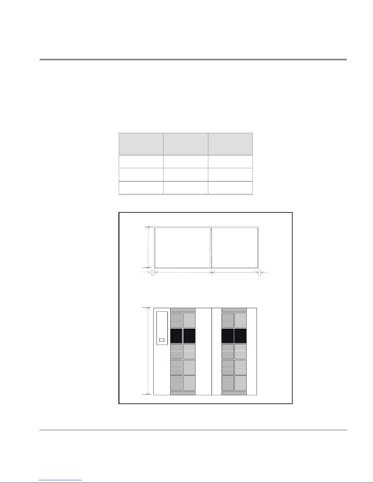
Dimensions
A minimum HP SureStore E Disk Array XP512 configurat ion consists of
one DKU and one DKC, with these approximate dimensions:
Minimum
Dimensions
Height 1790 70.50
Width 1350 53.20
Depth 800 31.52
800
mm in
7RS9LHZ
Preparing for Installation
16
1790
718
)URQW9LHZ
600
16
21
Page 22

800
600
A maximum HP SureStore E Disk Array XP512 configuration consists of
six DKUs and one DKC, with these approximate dimensions:
Maximum
Configuration
mm in
Height 1790 70.5
Width 4350 171.2
Depth 800 31.5
7RS9LHZ
16
1790
600
DKU
600
DKU
600
DKU
718
)URQW9LHZ
DKC
600
600
DKU
DKU
600
DKU
16
22
HP SureStore E Disk Array XP512: Site Prep Guide
Page 23

HP SureStore E Disk Array XP512 Weight
A minimum HP SureStore E Disk Array XP512 configurat ion consists of
one DKU and one DKC. A maximum HP SureStore E Disk Array XP512
configuration consis ts of six DKUs and one DKC. The table below
provides an approximate weight of each configuration:
Weight kg lbs
Minimum configuration 910 2006
Maximum configuration 3136 6911
Specific Component Dimensions And Weights
The following two tables provide the physical dimensions and weights
for each HP SureStore E Disk Array XP512 frame component. The
values listed in these tables are approximate and should be used for
general reference only; use these values to estimate the hallway and
door clearances as well as floor strength for moving the subsystem
frames.
HP SureStore E Disk Array XP512 Dimensions
Component Wid th Depth Height
DKU
product alone
DKU
packaged
DKC
product alone
DKC
packaged
600 mm
23.62 in
890 mm
35 in
750 mm
29.5 in
890 mm
35 in
800 mm
31.50 in
1000 mm
39.37 in
800 mm
31.50 in
1000 mm
39.37 in
1790 mm
70.53 in.
2020 mm
79.58 in
1790 mm
70.53 in
2020 mm
79.58 in
Weight Fully
Loaded
480 kg
1056 lb
539 kg
1185.5 lb
480 kg
1056 lb
537 kg
1181.5 lb
Preparing for Installation
23
Page 24

HP SureStore E Disk Array XP512 Component Weights
Product Description kg lb
A5951A DKC for 50/60 Hz 3-phase 395 870.8
A5951A
Opt 001
A5951A
Opt 002
Disk control frame (parent) for 60 H z
operation: 1 phase power
Disk control frame (parent) for 50 H z
operation: 1 phase power
395 870.8
395 870.8
A5951AX Disk control frame with 1 ACP pair 346 762.8
A5962AX 1GB cache memory 0.1 0.2
2 x A5963AX 256 MB shared memory 0.2 0.4
A5961AX CHIP power supply 15 33
Accessories: manual, code, skirts, terminators, etc. 5 11
A5953A 4-ExSA channel adapter pair 2.0 4.41
A5954A 8-ExSA channel adapter pair 4.0 8.82
A5956A 8 Port Fiber Channel adapter pair 4.0 8.82
A5961A Additional CHIP power supply 8.0 17.64
A5962A 1GB cache memory 0.1 0.22
A5963A 256 MB shared memory module 0.1 0.22
A5964A Additional ACP pairs 3.5 7.72
A5966A 18 GB array group, 4 drives per group 8.5 18.74
A5967A 47 GB array group, 4 drives per group 9 19.84
A5974A FC cable set for DKC frame to L1 frame 2 4.41
A5966S 18 GB spare drive 2.1 4.63
A5967S 47 GB spare drive 2.3 5.07
24
HP SureStore E Disk Array XP512: Site Prep Guide
Page 25

HP SureStore E Disk Array XP512 Upgrade Product Weights
Product Description kg lb
A5953U 4-ExSA channel adapter pair 2.0 4.41
A5954U 8-ExSA channel adapter pair 4.0 8.82
A5956U 8 port Fibre Channel adapter pair 4.0 8.82
A5961U Additional power supply for chips 3 to 4 8.0 17.74
A5962U 1GB cache memory 0.1 0.2
A5963U 256MB shared memory module 0.1 0.2
A5964U Additional ACP pair 3.5 7.72
A5965A
Opt 001
A5965A
Opt 002
A5965A
Opt 003
A5965A
Opt 004
60 Hz disk array frame with 2 disk canister mount
267 588.6
platforms: 3 phase power
60 Hz disk array frame with 1 canister
197 434.3
mount platform
Additional disk canister mount platform 70 154
50 Hz disk array frame with 2 disk canister mount
267 588.6
platforms: 3 phase power
60 Hz disk array frame with 2 disk canister mount
267 588.6
platforms: 1 phase power
60 Hz disk array frame with 1 canister
197 434.3
mount platform
Additional disk canister mount platform 70 154
(continued)
50 Hz Disk Array frame wit h 2 di sk cani ster mount
267 588.6
platforms: 1 Phase Power
50 Hz disk array frame with 1 canister
197 434.3
mount platform
Additional disk canister mount platform 70 154
A5966U 18GB array group, 4 drives per group 8.59 18.74
A5967U 47GB array group, 4 drives per group 9 19.84
Preparing for Installation
25
Page 26

HP SureStore E Disk Array XP512 Upgrade Product Weights (continued)
Product Description kg lb
A5966SU 18GB spare drive 2.1 4.63
A5967SU 47GB spare drive 2.3 5.07
A5974U FC cable set for DKC frame to L1 (frame #4) 2 4.41
A5975U FC cable set for frame R2, R3, L2 or L3 1 2.21
26
HP SureStore E Disk Array XP512: Site Prep Guide
Page 27

Service and Cable Routing Space Requirements
This section contains information about space requirements for the HP
SureStore E Disk Array XP512. Thi s data should be used as a guideli ne f or
space planning development.
The service clearance is the additional flooring space required to access
your HP SureSto re E Dis k Ar ray XP512. This space should be reserved for
the disk array; never use this space for storage.
HP recommends that you prepare a revised floor plan showing the overall
location and a rr ange ment of your computer room, including t he addition of
your disk array. Enough room and lightin g should be pr ovided for people to
work effectively on a da ily basis and for periodic servicing of equipment.
Select a location that ca n accommoda te the a dditi on of more DKU cabinet s
as your requirements increase. Be sure to consider interconnecting cables
and power cord leng ths when planning your layout. Identif y t he location of
all power outlets on the floor plan. Plan to keep cables away from traffic
areas to help prevent accident s and equipment fai lures. Prior to ins tallat ion,
consult your site specialist responsible for your computer room.
Preparing for Installation
HP strongly discou rages th e use of c arpetin g, includi ng anti- static var ieties,
within 6.0 m (20 ft.) of the disk array. If this advice is not foll owed, you
should place stat ic dischar ge mats where per sonnel must walk across befor e
touching any part of the array. Failure to comply with this prec aution can
result in equipment damage through static discharge.
If you are planning to construc t a new computer room or modify an exi sting
site, first consult with your HP representatives and local contractors. It is
important to plan the site with future expansion in mind so that equipment
can be added without disturbing the computer-systems operation.
The computer room floor must be able to support the total weight of the
equipment as well as localized weight at each caster or foot of the
equipment cabinets. A common method of preparing an adequate floor for
a computer room is to co nstru ct a ra ised f loor ov er the buildi ng flo or. The
weight should be spread evenly and the fl ooring should provide an area
27
Page 28

through which interconnecting cables can be run conveniently and
unobtrusively, and allows optimum distribution of conditioned air. Raised
floor access ramps must not exceed 10
° slope.
To estimate floor strength, the following items should be considered:
• The total weight of the equipment (the unpacked and packaged
weights are listed in this chapter)
• The total weight of furniture such as desks, chairs, and storage
cabinets
• Total approximate weight of computer room personnel
• Weight of moving equipment such as forklifts, dollies, and so on.
Any questions regarding the adequacy of airflow construction should be
referred to and evaluated by a qualified structural engineer.
Caution
In addition to determining the adequacy of the computer site floor, ensure
that all floors, stairs, and elevators which might be used when the disk
array is moved to its destination can support the weight and size of the
equipment. Failure to comply can result in damage to the equipment.
Maximum point floor loading is 500kg (1102.3 lbs). The minimum service
access is:
rear: 800m (31.5 in)
side: 0 mm
front: 800m (31.5 in)
28
HP SureStore E Disk Array XP512: Site Prep Guide
Page 29
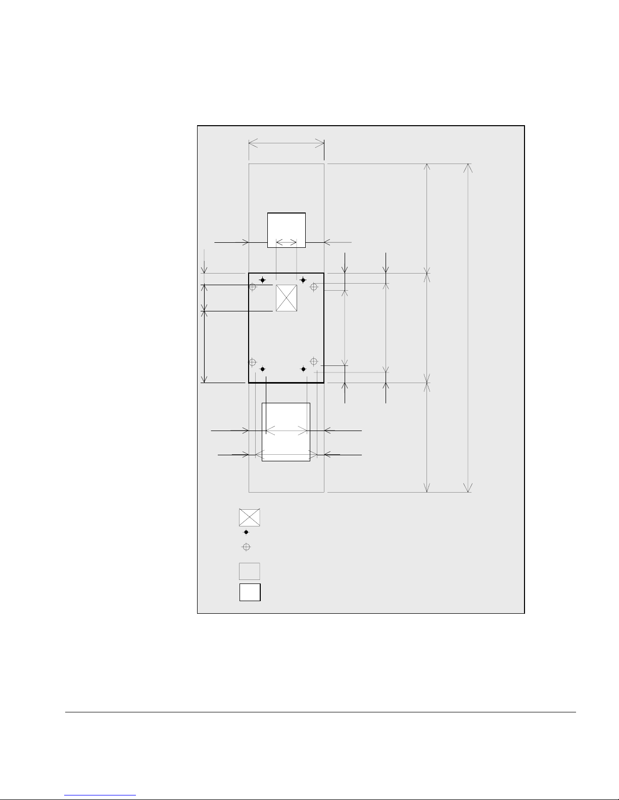
DKU Service Clearance (mm)
225
70
200
530
150
600
G
150
G
300
46070
225
150
70
115
570
115
60
680
60
(Unit: mm)
800
800
800
2400
Preparing for Installation
Front
Floor cutout area for cables
Screw jack
Caster
Service clearance
G
Grid panel(Perforated tile) (over 450mm
x 450mm)
29
Page 30

DKU Service Clearance (in)
8.9”
2.8”
7.9”
20.9”
5.9”
23.6”
G
5.9”
G
11.8”
18.1”2.8”
8.9”
5.9”
2.8”
4.5”
22.4”
4.5”
2.4”
26.8”
2.4”
(Unit: inches)
31.5”
31.5”
94.5”
31.5”
30
Front
Floor cutout area for cables
Screw jack
Caster
Service clearance
G
Grid panel(Perforated tile) (over 17.7”
x 17.7”)
HP SureStore E Disk Array XP512: Site Prep Guide
Page 31
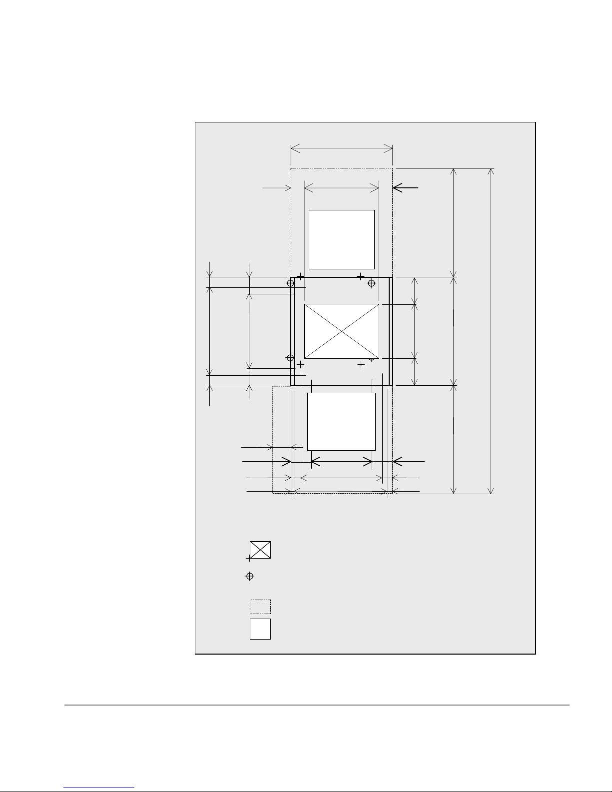
DKC Service Clearance (mm)
60
680
60
118
564
118
90
750
570
G
G
90
200
400
200
(Unit: mm)
800
800
2400
Preparing for Installation
280
166 418
86
16
578
718
Front
Floor cutout area for cables
Screw jack
Caster
Service clearance
Grid panel(Perforated tile) (over 450mm x
G
450mm)
800
166
86
16
31
Page 32

DKC Service Clearance (in)
2.4”
26.8”
2.4”
4.6”
22.2”
4.6”
11.0”
6.5”
3.4”
0.6”
3.5
29.5"
”
22.4”
G
G
(Unit: inches)
”
3.5
7.9”
15.7”
7.9”
31.5”
31.5”
94.5
”
31.5”
16.5”
22.8”
28.3”
6.5”
3.4”
0.6”
32
Front
Floor cutout area for cables
Screw jack
Caster
Service clearance
Grid panel(Perforated tile) (over 450mm x
G
450mm)
HP SureStore E Disk Array XP512: Site Prep Guide
Page 33

Minimum Configuration Service Clearance (mm)
8
1350
118
60
68060564
11
200
400
200
16
*2
b *1a *1
150
Front
225
300
460 8657886
600718
241
G
70
200
530
G
166
16
57090
G
G
418166
d
115
570
115
(U n it: m m)
800
60
680
800
60
800
c *1
2400
Preparing for Installation
Floor cutout area for cables
DKC
DKU
Screw jack
Caster
Service clearance
G
Grid panel (over 450m m x 450m m )
1. Clearance (a+b) d epends on the floor loa d rating and clear ance C. Floor
load ratings are shown below.
2. Clearance (d) must be mo re than.28m to allow for t he DKC front doo r .
33
Page 34

Minimum Configuration Service Clearance (in)
2.4”
26.8”
2.4”
4.6”
22.2”
4.6”
7.9”
15.7”
7.9”
0.6”
53.2”
8.9”
22.4”3.5”
G
G
16.5”6.5”
5.9”
G
G
11.8”
18.1” 3.4”22.8”3.4”
23.6”28.3
b *1a *1
9.5”
70
7.9”
20.9”
6.5”
0.6”
4.5”
22.4”
4.5”
(Unit: inches)
31.5”
2.4”
26.8”
31.5”
2.4”
31.5”
94.5”
34
*2
d
Front
c *1
Floor cutout area for cables
DKC
DKU
Screw jack
Caster
Service clearance
G
Grid panel(Perforated tile)
(ov er 17 .7 ” x 1 7.7 ”)
HP SureStore E Disk Array XP512: Site Prep Guide
Page 35

Required Clearance (a + b) (m)
Floor Load Rating
2
(kg/m
)
Clearance (C) (m)
C=0 C=0.2 C=0.4 C=0.6 C=1.0
500 00000
450 0.20000
400 0.5 0.3 0.1 0 0
350 0.9 0.7 0.5 0.3 0
300 1.6 1.3 1.0 0.8 0.4
Preparing for Installation
35
Page 36

a *1
Maximum Configuration Service Clearance
4350(171.3)
(Unit: mm (in c h e s))
b *1
16
(.6)
600
(23.6)
G
DKU
G G GG
600
(23 .6 )
600
(23.6)
G
DKU
718
(28.3)
GG
Front
DKC
GG
600
(23.6)
G
DKU DKU
600
(23.6)
G G
DKUDKU
G
600
(23.6)
16
(.6)
800
(31 .5 )
800
(31 .5 )
800
(31 .5 )
2400
(94 .5 )
C *1
1. Clearance (a+b) d epends on the floor loa d rating and clearanc e C. Floor
load ratings are shown below.
36
Floor cutout area for cables
Screw jack
Caster
Service clearance
G
Grid panel(Perforated tile) should be at
least 450mm(17.7”) x 450mm(17.7”)
HP SureStore E Disk Array XP512: Site Prep Guide
Page 37

Required Clearance (a + b) (m)
Floor Load Rating
2
(kg/m
)
Clearance (C) (m)
C=0 C=0.2 C=0.4 C=0.6 C=1.0
500 0.20000
450 0.9 0.3 0 0 0
400 1.8 1.1 0.6 0.2 0
350 3.2 2.4 1.7 1.1 0.3
300 5.4 4.3 3.4 2.7 1.6
Adding Additional DKUs
Your disk array can consist of up to 6 DKUs. A minimum configuration
consists of one DKC and one DKU. The following diagram depicts the
order and placement of additional DKUs:
DKU 6
Preparing for Installation
DKU 4
DKU 3
DKC
DKU 1
DKU 2
DKU 5
37
Page 38

Data Comm Requirements
Route data communications cables away from areas of high static electric
fields created by power transformers and heavy foot traffic. Use shielded
data comm cables that meet approved industrial standards to reduce the
effects of external fields.
Phone Home With Continuous Track
The HP SureStore E Disk Array XP512 Phone Home capabilities detect
and report problems even before they are noticed by operators and users.
Continuous Track, a program that resides in the DKC, will phone “home”
to HP Stres-Free Central control center and will provide:
• periodic “well” checkups
Every 24 hours, Continuous Track will call HP Stress-Free Central.
When a successful conn ection is ma de, a preconfigur ed set of fil es will
be transferred from the DKC to the HP Stress-Free Central control
center. Your HP CE will set the time of call and set up the files to be
transferred. This check-up ensures the health of your disk array, on a
day-to-day basis.
38
• incidental “sick” calls
When an error occurs, a service information message (SIM) is
generated. The SIM is stored in the DKC for use by your HP service
representa tive. The Con tinuous Track remote maintenance tool also
reports the SIMs to the HP Stress-Free Central control center. SIMs
are classified according to severity, and many SIMs do not require
immediate attention. These SIMs are often addressed during routine
maintenance, and are corrected before a failure occurs. Serious-level
and acute-level SIMs are reported to HP Stress-Free Central
immediately to ensure that the problem is addressed as soon as
possible.
To activate Phone Home, these requirements are necessary:
• dedicated analog phone line
• an HP CE to configure Continuous Track
HP SureStore E Disk Array XP512: Site Prep Guide
Page 39

Local Area Network (LAN)
Two software products are especially useful in managing your disk array:
• HP SureStore E Remote Control XP
• HP SureStore E Command View XP
Remote Control XP and Your Private LAN
HP SureStore E Remote Control XP is a software application that permits
you to connect to, monitor, and manage up to 8 disk arrays. It
communicates directly with the DKC of each attached disk array. The
software runs on a PC called a remote console. The remote console is
attached over a special private LAN. The private LAN is dedicated to the
remote console, and is not used for any other purpose. There are two ways
to connect your HP SureStore E Disk Array XP512 to the private LAN:
• via the private LAN port in the DKC
If you are using HP Remote Control XP to manag e the local dis k array
only, then your CE will connect your remote console PC directly to
your HP SureStore E Disk Array XP512, using the internal LAN port
included in your DKC. Refer to your HP Remote Contr ol XP manual
for PC requirements.
Preparing for Installation
LAN Hardware needed: One twisted-pair LAN cable
• via a hub
If you are us ing Remote Control XP to manage multip le disk arrays,
then your CE will connect your remote console PC and all disk arrays
to a network hub.
LAN Hardware needed:
one twisted-pair LAN cable for each managed disk array
one twisted-pair LAN c able for the remote console PC
one network hub
39
Page 40

HP SureStore E Command View XP and Your Public Intranet
HP SureStore E Command View XP is a web-based software application
that permits you to connect to, monitor, and manage disk arrays. You can
remotely manage your HP SureStore E Disk Array XP512 from any
location, enabling a remote expert to participate in problem management.
To connect to your Intranet (public LAN), your CE will directly connect
your HP SureStore E Disk Array XP512 to an available Ethernet port on
your public LAN. T o e nsure network secur ity , con sult with your HP CE and
your network administrator before selecting the appropriate location of
your LAN drop.
Network Hardware needed:
Outside Phone Line
• one twisted pair (Cat 5) cable
• one available LAN drop on your Intranet
Recommendation Install a public voice phone line near your disk array. This phone line will
be used by you and your HP CE for voice communication in and outside of
your facili ty.
40
HP SureStore E Disk Array XP512: Site Prep Guide
Page 41

Electrical Requirements
Power requirements are one of the most important considerations prior to
installing your disk array. Each disk array has two separate connections to
AC power, so the rated AC current should be doubled. In case one input
fails, the second input MUST BE CAPABLE OF SUPPORTING THE
ENTIRE CURRENT DEMAND FOR BOTH SETS OF POWER
SUPPLIES.
Line Voltage
The line voltage (AC) at the wall power outlet is a function of the local
power utility and your building power distribution network. Voltages
outside the operating range of the disk array can cause intermittent system
errors or a complete system shutdown. If required, the HP CE along with
your electrician can determine the current line voltage and make
recommendations. Avoid the use of a line voltage conditioner.
Make sure that dis tribution u nit s upports the c orrect v oltage t o support your
entire system.
Branch Circuit Breakers
Three-Phase Branch Circuit Breakers
The power cord supplied with each DKU is sized for connection to a 30amp circuit. This specification per phase is based on the input power
requirements of the first DKU in the subsystem since the first DKU
supplies power to the DKC.
Single-Phase Branch Circuit Breakers
With the single-phase power option, both the DKU and the DKC are
connected to the AC main. The power cord supplied with the DKU and
each DKU is sized for connection to a 20-amp circuit.
Preparing for Installation
41
Page 42

Frequency
AC line frequency is normally determined by your local power providers.
In some cases, electrical power is supplied by motor-generators. Shifts in
AC line frequency can cause system errors. Your HP CE can monitor the
frequency of the input AC line power and make recommendations, if
necessary.
AC Line Voltage Requirements for the HP SureStore E Disk Array XP512
The basic AC power requirements are as follows:
1-Phase 60Hz Operation 60Hz-V1 60Hz-V2s 60Hz-V3
Nominal rated voltage (Vac) 200 208 230
Minimum operating voltage
(Vac)
Maximum operating voltage
(Vac)
Rated line current: DKU
(Arms)
Rated line current: DKC
(Arms)
Dropout carry-thru time at
minimum line voltage (ms)
184 191 212
212 220 244
12.3 11.9 10.8
5.7 5.6 5.2
500 500 500
42
HP SureStore E Disk Array XP512: Site Prep Guide
Page 43

1-Phase 50Hz Operation 50Hz-V1 50Hz-V2s 50Hz-V3 50Hz-V4
Nominal rated voltage (Vac) 200 220 230 240
Minimum Operating Voltage
184 202 212 221
(Vac)
Maximum Operating Voltage
212 233 244 254
(Vac)
Rated Line Current: DKU
12.3 11.1 10.8 10.5
(Arms)
Rated Line Current: DKC
5.7 5.3 5.2 5.1
(Arms)
Dropout carry-thru time at
500 500 500 500
minimum line voltage (ms)
3-Phase 60Hz Operation 6 0Hz -V1 60Hz-V2s 60Hz-V3
Nominal rated voltage (Vac) 200 208 230
Minimum operating voltage
184 191 212
(Vac)
Preparing for Installation
Maximum operating voltage
212 220 244
(Vac)
Rated line current (Arms) 15 14.7 13.2
Dropout carry-thru time at
500 500 500
minimum line voltage (ms)
Nominal rated voltage (Vac) 200 208 230
43
Page 44

3-Phase 50Hz Operation 50Hz-V1 50Hz-V2s 50Hz-V3 50Hz-V4 50Hz-V5 50Hz-V6 50Hz-V7
Nominal rated voltage (Vac) 200 220 230 240 380 400 415
Minimum operating voltage
184 202 212 221 350 368 382
(Vac)
Maximum operating voltage
212 233 244 254 403 424 440
(Vac)
Rated line current (Arms) 15 13.8 13.2 12.6 9.9 9.6 9.5
Dropout carry-thru ti me at
500 500 500 500 500 500 500
minimum line voltage (ms)
Nominal rated voltage (Vac) 200 220 230 240 380 400 415
Safety and Dedicated Ground
The primary reason for grounding electrical systems is safety. The safety
ground is required by the National Elec tric Code (USA) and most other
local, regional, and national codes. In addition to safety ground, HP
requires that a dedica te d (eart h refer ence) gro und be in stall ed as a common
reference point for all system components. You should consult with your
HP CE and your electrician to ensure that your electrical system meets all
local and national safety codes.
HP SureStore E Disk Array XP512 Grounding Requirements
Your subsystem must meet all of the following conditions:
• An insulated grounding conductor that is identical in size and
insulation material and thickness to the ungrounded branch-circuit
supply conductors. It should be green, with or without yellow stripes,
and is to be installed as a part of the branch circuit that supplies the
unit or system.
• The grounding conductor mentioned above should be grounded to
earth at the service equipment or other acceptable building earth
ground such as the building frames (in case of a high rise steel-frame
structure).
44
HP SureStore E Disk Array XP512: Site Prep Guide
Page 45

Receptacles
When receptacles are used to connect your disk array components to AC
power, they must include a dedicated ground connection that is insulated
from the receptacle . It is important that the recep tacle box be groun ded with
an additional ground connection that is nondedicated. The additional
ground can be hard conduit.
Each disk array has two separate connections to AC power, and the second
input must be capab le of supporting the entire current demand f or bot h s ets
of power supplies.
When installing the r ec ept acl es, make sure that each r ece pta cl e has it s own
neutral (if required) and ground. Using the same neutral/ground for more
than one circuit will cause voltage loss, heat problems, and can result in a
fire hazard. A shared neutral conductor that fails open-circuit will result in
possible over-voltage damage to equipment.
For 3-phase 60Hz operation, the outlet must be either:
• Connector Russell & Stoll 3934 or
• Receptacle Russell & Stoll 3754
The plug type provided with the power cord is a
• Russell & Stoll 3760
• Russell & Stoll 3760PDG
Power Line Transients
Heavy electrical loads from nearby machinery or equipment (elevators,
electric welders, etc.) can cause intermittent system errors, even if that
equipment is on a separate circuit breaker. When faced with these
conditions, you should provide a separate, completely independent power
panel with an isolated ground and circuit breaker coming directly from the
main building power source or secondary power source.
Preparing for Installation
45
Page 46

If necessary, your HP CE can measure your power line noise level and
make appropriate recommendations concerning the use of line treatment
devices.
Maximum Peak Inrush and Crest Factor
The inrush current for the HP SureStore E Disk Array XP512 is:
3-Phase
60 amps fo r the first DK U
25 amps for 2nd DKU
Single-Phase
50 amps fo r the first DK U
40 amps for DKC
Crest Factor
The crest-factor for the HP SureStore E Disk Array XP512 is 1.68.
46
HP SureStore E Disk Array XP512: Site Prep Guide
Page 47

Sources of Electrical Interference
Ensure that the disk array is protected from sources of electrical
interference:
wall outlets Convenience power outlets for building maintenance
equipment (vacuum cleaners, floor buffers, etc.) must
be wired from circuit breakers on a power panel
separate from the computer system panel. The ground
wires from these outlets must be connected to the
normal building di stributio n panel and n ot to the s ystem
ground.
If a separate power source and separate ground are not
provided, operation of janitorial equipment can induce
electric noise and cause abnormal operation of the
computer system. Your electrician can verify whether
or not maintenance outlets are on separate panels.
lightning In some geographical areas it may by advisable to
install lightning protection for both personnel and
computer systems.
Preparing for Installation
The principles of lightning protection and personnel
safety are outlined in detail in the lightning protection
code contained in the National Fire Protection
Association (NFPA) Handbook.
vibration Continuous vibration can cause a slow degradation of
mechanical parts and, when severe, can cause data
errors in disk drives. Mechanical connections such as
printed circuit assembly (PCA) conductors, cable
connectors, and pr ocesso r ba ckpla ne wiri ng can also b e
affected by vibrations.
electromagnetic int erference
The disk array is specifically designed to reduce its
susceptibility to radiated and conducte d interference.
Electromagnetic interference can cause a variety of
system problems. Your HP CE can advi se you about
47
Page 48

many of the most common causes of electromagnetic
interference.
metal If metal is used in the construction of the raised floor,
ensure that there is a common ground connection
between the raised floor and main floor to avoid
possible build up of di fferen t voltage pot ential s. Failure
to comply can result in serious injury to personnel and
damage to equipment.
flammable materia ls
Fundamental safeguards for disk arrays should include
a site well away from any sources of potential damage.
The system should not be installed or operated in an
environment where there is a risk of fire or explosion
due to the presence of highly flammable gases, volatile
liquids, or combustible dust.
airborne contaminants
Airborne contaminants and particles of a certain size
and hardness can damage you r disk a rrays. Some of t he
most common contaminants are dust, smoke, ash,
eraser debris, food crumbs, and salty air.
48
Your HP CE can assist you in determining whether or
not you need be concerned about airborne
contaminants.
HP SureStore E Disk Array XP512: Site Prep Guide
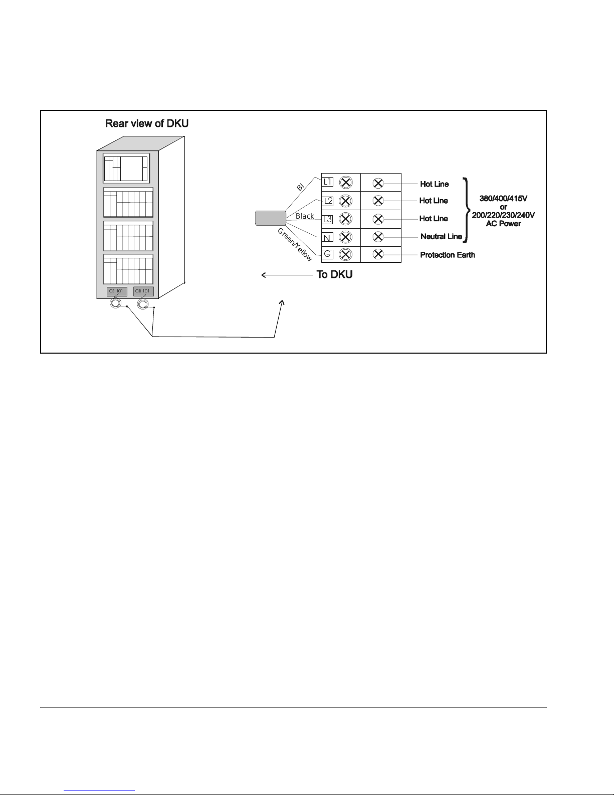
Page 49

3-Phase AC Cabling for USA
Connecting the External Power Supply Cord
The DKU has two power supply cords. If one power source malfunctions,
the other power source will assume th e total load, ca using no da ta loss . It is
also good practice t o put each power cor d on a dif ferent electrical circuit , in
case of a circuit failure. Each power supply cord is supplied with an
attachment plug type R&S FS 3760. Be sure to prepare the following
socket receptac les betwee n the power distribut ion board of the bu ilding an d
the attachment plugs for the unit:
Socket receptacle: R&S FS 3754 or FS 3934 (or equivale nt)
Branch Circuit Requirements
To protect your disk array, your building must be wired correctl y. Each line
(R/S/T line) should be protected by a short circuit protective device and by
an overcurrent protective device rated 30 amp on building installation.
Preparing for Installation
49
Page 50

The protective device on building installation shall comply with national
standards of the country where the units shall be instal led, and if a
protective device interrupts a conductor, it shall also interrupt all other
supply conductors
This protection is not required for the neutral line of this unit.
50
HP SureStore E Disk Array XP512: Site Prep Guide
Page 51

3-Phase AC Cabling for Europe
Caution
The DKC and the basic DKU commonly have two main disconnect devices
(two main breakers for dual power lines) so that AC Power of the unit can
be supplied from the separate power distribution board with two power
supply cords. Similarly, each of the 2nd DKU, the 3rd DKU, the 4th DKU,
the 5th DKU, and the 6th DKU also has two main disconnect devices.
Observe all instructions described in this manual before connecting the
equipment to the power source and before servicing.
Connecting the Power Supply Cord
50Hz European disk arrays are shipped with an unterminated power cord.
Your electrician must select and install the correct power plug. Be sure to
prepare the following socket receptacles and power cords between the
power distribution board of the building and the attachment plugs for the
unit:
A power cord of type H07RN-F or equivalent, with five 6.0mm
provided with the unit.
2
is
Preparing for Installation
Be sure to connect a power c ord to th e distri butio n box as illu strat ed bel ow.
Miswiring of the neutral conductor may cause damage to your disk array.
To reduce the risk of a wrong connection, you should use a plug and sock et
that is approved for this disk array. It is your electrician’s responsibility to
select and instal l the proper plug.
51
Page 52
&%
&%
High leakage current may occur betw een the power supp ly and the unit . To
avoid an electrica l shock, be sure t o perform the protec tive earth co nnection
before the supply connections are made.
Branch Circuit Requirements
k
c
/
a
l
B
n
/
w
o
r
B
B
c
l
a
k
/
B
l
u
G
e
r
e
e
n
/
Y
e
l
l
o
*
w
52
To protect your disk array, your building must be wired correctl y. Each line
(R/S/T line) should be protected by a short circuit protective device and by
an overcurrent protective device rated 30 amp on building installation.
The protective devices on building installation shall be comply with
national standards of the country where the units shall be installed, and if a
protective device interrupts a conductor, it shall also interrupt all other
supply conductors.
HP SureStore E Disk Array XP512: Site Prep Guide
Page 53

Single-Phase AC Cabling for USA
Caution
The DKC has two main disconnect devices (two main Breaker CB200s for
dual power lines) so that AC Power of the unit can be supplied from the
separate power distribution board with two power supply cords. Similarly,
each of the 1st DKU, the 2nd DKU, the 3rd DKU, the 4th DKU, the 5th
DKU, and the 6th DKU also has two main disconnect Devices (two main
breaker CB101s for dual power lines).
described in this manual before connecting the equipment to the
power source and before servicing.
Connecting the Power Supply Cord
The unit has two power supply cords with attachment plug type R&S
5720DP/0625. Be sure to prepare the foll owing socke t recep tacle s between
the power distribution board of the building and the attachment plugs for
the unit:
• Socket receptacle: R&S 3743 or 3913
• The power cord that is provided with your disk array is type SJT or
equivalent, nonshielded type, with three min. #10 AWG conductors,
terminated at one end with an assembled socket receptacle cap.
Observe all instructions
Preparing for Installation
53
Page 54

&%&%
54
HP SureStore E Disk Array XP512: Site Prep Guide
Page 55

Branch Circuit Requirements
To protect your disk array, your building must be wired correctl y. Each line
(U/L1, V/L2 line) should be protected by a short circuit protective device
and by an overcurrent protective device rated 20 amp on building
installation.
The protective de vice on bu ilding i nstalla tion sha ll be comply wi th natio nal
standards of the country where the units shall be installed, and if a
protective device interrupts a conductor, it shall also interrupt all other
supply conductors.
Preparing for Installation
55
Page 56

Single-Phase Cabling for Europe
Caution
The DKC has two main disconnect devices (two main breaker CB200s for
dual power Lines) so that AC Power of the unit can be supplied from the
separate power distribution board with two power supply cords. Similarly,
each of the 1st DKU, the 2nd DKU, the 3rd DKU, the 4th DKU, the 5th
DKU, and the 6th DKU also has two main disconnect devices (two main
breaker CB101s for dual power Lines). Observe all instructions described
in this manual before connecting the equipment to the power source and
before servicing.
Connecting the Power Supply Cord
The unit ha s two power supply co rds. The pow er cord inc luded with the
unit is a type H07RN-F or equivalent, with five 2.5 mm
Socket Receptacle: As shown in the following figure.
2
conductors.
56
/
/
e
u
Bl
G
/
n
e
e
r
*
Y
e
l
l
w
o
HP SureStore E Disk Array XP512: Site Prep Guide
Page 57

&%
&%
Be sure to connect a power cord to the distribution box as illustrated in the
figure below. To reduce the risk of a wrong connection, use a socket
approved for this dis k array.
/
/
e
l
u
B
G
e
e
r
n
*
/
Y
e
l
o
l
w
High leakage current may occur betw een the power supp ly and the unit . To
avoid an electrica l shock, be sure t o perform the protec tive earth co nnection
before the supply connections are made.
Branch Circuit Requirements
To protect your disk array, your building must be wired correctl y. Each line
(U/L1, V/L2 line) should be protected by a short circuit protective device
and by an overcurrent protective device rated 20 amp on building
installation.
The protective device on building installation shall be comply with
National Stan dards of the country wher e the units shall be insta lled, and i f a
protective device interrupts a conductor, it shall also interrupt all other
supply conductors.
Preparing for Installation
57
Page 58

Uninterruptible Power Supply (UPS)
Most HP SureStore E Disk Array XP512 units are installed in data centers
where an uninterruptible power system (UPS) strategy is already in place.
However, if you are making your first large disk array purchase, you may
have a need for a separate UPS solution. HP references the Silcon DP300
series UPS solution. The Silcon DP300 is product from American Power
Conversion Corp (APC), manufacturers of uninterruptible power systems.
UPS Features
The APC UPS, Silcon DP300 series, provides the following feature set:
• Protection agains t short line transient s
• Continued availability during short duration power failures (A
minimum of 30 minutes for a fully-configured system)
• Stable AC output voltage
UPS Limitations
• LCD display unit with ability to display key AC input/output
parameters, alarm log, events log and programming functions
• Communications Interface option for communicating a remote UPS
shutdown through the serial port connection.
While the UPS will provide uninterru pted power to the XP array in the
event of a power failure, once the battery runtime is exceeded, it will shut
down, resulting in a loss of AC power to the array. The UPS does have the
ability to communicate an oncoming shutdown to the host via the Silcon
Triple Chas sis. The host can then p ass t his mes sag e in- band to the XP arra y
using the “xppf” program.
58
HP SureStore E Disk Array XP512: Site Prep Guide
Page 59

Power Requirements: Single Secondary Input (Primary Offline)
This is based on a worst-case voltage (Vac input 10 percent) and a
maximum configuration for disk control and disk array frames. A phase
imbalance of 15 percent is also included in the calculati on.
First DKU/DKC
Input (Vac )
Combination
208 25.0 A (9.0kVA) 15.0 A (5.4kVA)
400 16.3 A (11.3k VA) 9.9 A (6.9K VA)
Reference Supplier Information
American Power Conversion
32 Fairgrounds Road
West Kingston, RI 0289
Phone Numbers:
Technical Support & Product Info.
1-800-800-4272
Corporate
1-800-788-2208
1-401-789-5735
Each Additional
DKU
To find out more about the recommended American Power Conversion
UPS, travel to the APC web site:
You can also contact your HP service representatives for specific
configuration needs for your area.
Preparing for Installation
www.apcc.com
59
Page 60

Environmental Requirements
The environmental specification for operating your disk array must be
satisfied prior to installation.
Air Conditioning Ducts
Use separate computer room air co nditioning duc t work. If i t is not se parate
from the rest of the building, it might be difficult to control cooling and air
pressure levels. Duct work seals are important for maintaining a balanced
air conditioning system and high static air pressure . Adequate cooling
capacity means little if the direction Humidity levels may increase if the
ducts are exposed to warm air.
Humidity
Maintain proper humidity levels. High humidity levels causes galvanic
actions to occur between some dissimilar metals. This eventually causes a
high resistance between connections, leading to equipment failure.
60
Caution
Low humidity contributes to undesirably high levels of electrostatic
charges . Th is i ncreases the electr ost atic disch arge (ESD) voltage potential .
ESD can cause component damage during servicing operations.
Static charges (voltage levels) occur when objects are separated or rubbed
together. The voltage level of a static charge is determined by the following
factors:
• types of materials
• relative humidity
• rate of change or separation
HP SureStore E Disk Array XP512: Site Prep Guide
Page 61

Follow these precautions to minimize possible ESD-induced failures in
your computer room:
• Install conductive flooring (conductive adhesive must be used when
laying tile s).
• Use conductive wax if waxed floors are installed.
• Ensure that all equipment and flooring are properly grou nded and ar at
the same ground potential.
• Use conductive tables and chairs.
• Store spar e electric parts in antistatic containers.
• Maintain recommended hum idity level an airflow rates.
Low humidity levels are often the res ult of the facility heati ng system and
occur during the cold season. Most heating systems provide air with a low
humidity level, unless the system has a built-in humidifie r.
Dust and Pollution Control
For troublefree operation, disk drives require a dust-free environment, The
HP SureStore E Disk Array XP512 disk drive is protected from dust
particles by mechanical air filters designed to trap large dust particles.
Smaller particles can pass through some filters, and, over a period of time,
can cause problems in mechanical parts. Small dust particles ca n be
prevented from entering the computer room by maintaining its air
conditioning system at a high static air pressure level.
HP SureStore E Disk Array XP512 Temperature and Humidity
Specifications
When the disk array is operating, the recommended temperature range is
21°C to 24°C and recommended relative humidity range to be (at 22
between 50 to 55 percent. The following table lists the temperature,
humidity, and vibration specifications for the HP SureStore E Disk Array
XP512. The vibration and shock specifications apply to all three axes.
° C)
Preparing for Installation
61
Page 62

Caution
No condensation in and around the HP SureStore E Disk Array XP512
should be observed under any conditions.
Shipping and
Specification Operating
1
Nonoperating
2
Storage
3
Temperature (°C) 16 ~ 32 -10 ~ 43 -25 ~ 60
Relative humidity
4
(%)
20 ~ 80 8 ~ 90 5 ~ 95
Max wet bulb (°C) 26 27 29
Temperature
10 10 20
deviation (°C/
hour)
Vibration
5
0.25mm,
5 ~ 10Hz
0.05G,
10-300Hz
2.5mm,
5 ~ 10 Hz
0.5G,
10 ~ 70 Hz
0.05mm,
0.5, 15 min.
At four most
severe resonanc e
between
5~200Hz
6
70 ~ 99 Hz
1.0G,
99 ~ 300 Hz
Shock 8G, 15ms
Horizontal:
7
incline
impact:1.22m/s
1. Environmental specification for operating condition should be
satisfied before the disk subsystem is p owered on. Max. temperature
of 32ºC should be strictly satisfied at the air inlet portion. The
recommended tempe rature range is 21~24ºC.
62
8
Vertical:
rotational
edge:.15m
HP SureStore E Disk Array XP512: Site Prep Guide
Page 63

2. Nonoperating condition includes both packing and unpacking
conditions unless otherwise specified.
3. On shipping/storage condition, the product should be packed with
factory packing.
4. No condensation in and around the drive should be observed under
any conditions.
5. The specifications apply to all three axes
6. See ASTM D999-86 Standa rd Methods for Vibration Testing of
Shipping Containers
7. See ASTM D880-86 Standard Methods of Incline Impact Test for
Shipping Containers
8. See ASTM D775-80 Standard Methods for Drop Test for Loaded
Boxes.
Preparing for Installation
63
Page 64

Heat Dissipation
The following table describes the heat dissipation of the DKC and DKU
(fully loaded):
Heat Dissipation DKU
1
DKC
2
DKC
3
DKC
4
Power consumption (kVA) 3.14 3.72 1.57 2.41
Heat dissipation (kW) 2.85 3.43 1.46 2.32
BTUs per hour 9,727 11,707 4,983 7,918
kcal per hour 2,451 2,949 1,255 1,995
1. DKU fully configured with 18GB HDDs
2. DKU fully configured with 47GB or 72GB HDDs
3. DKC configured with 8GB Cache Memory, two fibre 8-port adapters
and one additional disk adapter
4. DKC fully configured
64
HP SureStore E Disk Array XP512: Site Prep Guide
Page 65

Altitude
When operating the HP SureStore E Disk Array XP512, the maximum
altitude is 3,000 meters. Nonoperational, the maximum altitude is 4,000
meters.
Preparing for Installation
65
Page 66

Acoustics
Computer equipment and air conditioning blowers cause computer rooms
to be noisy. Ambient noise level in a computer room can be reduced as
follows:
dropped ceiling Cover with a commercial -grade fire-resistant, acoustic
rated, fibe rglass ceiling tile.
sound deadening Cover the walls with sound-deadeni ng ma te ri al.
removable partitions
To be most effective, use foam rubber models.
acoustic emissions
7.63 Bels (A) sound power
59.8 dB (A) sound pressure, operator position
66
HP SureStore E Disk Array XP512: Site Prep Guide
Page 67

Delivery Space Requirements
There should be enough clearance to move equipment safely from the
receiving area to the computer room. Permanent obstructions, such as
pillars or narrow doorways, can cause equipment damage.
Delivery plans should include the possible removal of walls or doors. the
physical dimensions were summarized on page 23.
Preparing for Installation
67
Page 68

68
HP SureStore E Disk Array XP512: Site Prep Guide
Page 69

4
UPON RECEIPT OF YOUR HP
SURESTORE E DISK ARRAY XP512
Your HP SureStore E Disk Array XP512 is shipped directly from HP. If
your disk array is part of a system order, HP coordinates the shipment of
equipment from all locations so that it arrives at your site at approximately
the same time.
In some cases, factors beyond the control of HP can cause delivery delays.
If you have not received your equipment within a two week period, notify
your HP sales representative. The HP sales representative will trace your
order and expedite delivery.
Caution
Be sure to allow for size and weight in regards to placing the disk array at
its installation site. Refer to “Physical Requirements” (page 19) for
specific size and weight values.
69
Page 70

Checking for Shipping Shortage and Damage
As your disk array arrives, check the carr ier’s bill of lading carefully to
ensure that all items shipped by HP are deli vered. Notify the carr ier
immediately if there are any discrepancies or items missing.
Inspect all of the shipping containers for signs of damage before actually
unpacking the equi pment. Some typ ical signs of s hipping damage are dents,
scratches, cuts, or water marks. If any damage is found, note on the bill of
lading that there is apparent damage subject to inspection. Arrange for the
carrier’s representative and a representative from He wlett-Packard to be
present when the item in question is unpacked.
Regardless of the circumstances, the HP CE will take immediate action to
replace any damaged components without waiting for the settlement of
claims.
70
HP SureStore E Disk Array XP512: Site Prep Guide
Page 71

Unpacking the Cartons
The equipment cartons can be unpacked at your convenience; it is your
responsibility to have the equipment unpacked and moved to its proper
installation location prior to the day of installation.
Leave the packing list (invoice) for each carton that is to be unpacked and
ensure that each item on the list can be accounted for. Contact your HP
sales representative immediately if there are any missing items, or if the
items are not the same as you ordered.
Leave the sealed cartons of CDs, cables, and any other installation
hardware intact for the HP CE. Your HP CE and HP ASE will install and
configure your disk ar ray.
Upon Receipt of Your HP SureStore E Disk Array XP512
71
Page 72

72
HP SureStore E Disk Array XP512: Site Prep Guide
Page 73

INDEX
A
acoustics
XP512 66
altitude
XP512 65
American Power Conversion (APC)
supplier information 59
application software engineer (ASE)
site preparation team 12
C
cables
XP512 routing space 27
clearance
XP512 service 29
computer room
XP512 requirements 19
customer
site preparation responsibilities 13
customer engineer (CE)
site preparation team 12
D
damage, shipping
XP512 70
data communications
XP512 requirements 38
delivery
XP512 67
dimensions
XP512 21
E
electrical interference
sources of 47
electrical requirements
XP512 41
environmental requirements
XP512 60
F
floor
XP512 load 28
H
heat dissipation
XP512 64
73
Page 74

I
installation
XP512 17, 69
P
power cord
3-phase AC (Europe) 51
3-phase AC (USA) 49
single-phase (Europe) 56
single-phase AC (USA) 53
power supply
XP512 58
S
safety
XP512 18
sales representative (SR)
site preparation team 12
site preparation
checklist 14
physical requirements 21
preparations before delivery 16
team 12
W
weight
XP512 23
X
XP512
unpacking 71
74
HP SureStore E Disk Array XP512: Site Prep Guide
Page 75

Reader Comment Sheet
PRELIMINARY
HP SureStore E Disk Array XP512
Site Prep Guide
We welcome your evaluation of this manual. Your comments and suggestions will help us improve our publicatio ns. Remov e
this page and mail or FAX it to 916-785-2299. Use and attach additional pages if necessary.
Agree Disagree N/A
The manual is well organized.
The information is technically accurate.
Information is easy to find.
Step-by-step procedures are easy to perform.
There are enough examples and pictures.
The examples and pictures are useful.
Comments_________________________________________________________________________________
________________ ___________________ ___________________________________ __________
________________ ___________________ ___________________________________ __________
________________ ___________________ ___________________________________ __________
Name: Phone:
Title: FAX:
Company: E-mail:
Address: ZIP:
City & State: Country:
___ Check here if you would like a reply.
Hewlett-Packard has the right to use submitted suggestions witho u t obligation, with all such ideas becoming the property of Hewlett-Packard.
XPSO Roseville Information Engine er ing E0800 A5951-96150
Page 76

Please Do Not Staple
BUSINESS REPLY MAIL
FIRST CLASS MAIL P ERMIT NO. 256 ROSEVILLE, CA
POSTAGE WILL BE PAID BY ADDRESSEE
Attention: Information Engineering (MS 5668)
HPSO
Hewlett-Packard Company
8000 Foothills Blvd.
Roseville, CA 95747-9987
NO POSTAGE
NECESSARY
IF MAILED
IN THE
UNITED STATES
Fold Here
Tape Please Do Not Staple Tape
 Loading...