

Page 1

Site Prep Guide
HP SureStore E Disk Array XP48
Page 2

Notice
Safety notices
© 2000, Hewlett-Packard Comp any.
E1200 A5921-90900
Hewlett-Packard Company makes no warranty of any
kind with regard to this material, including, but not
limited to, the implied warranties of merchantability and
fitness for a particular purpose. Hewlett-Packard shall not
be liable for errors contained herein or for incidental or
consequential damages in c o nn ectio n with the furnish in g,
performance, or use of this material.
This document conta in s p rop rie ta ry info rm at ion , whic h is
protected by copyr ight. No part of this document may be
photocopie d, reproduced, or t ranslated into an other
language without the prior written consent of HewlettPackard. The informat ion contained in this document is
subject to change without notice.
Warranty
If you have any ques tions about the warra n ty f or t his
product, contact your dealer or loca l HP sales
representative.
Any servicing, adjustment, maintenance, or repair that
must be performed only by authorized service-trained
personnel.
Caution Denotes a hazard that can cause
hardware or software damage.
WARNING Denotes a hazard that can cause
personal injury or death.
Trademarks
Windows NT, Microsoft, Windows, MS Windows, and
MS-DOS are U.S. registered tradem arks of Microsoft
Corporation.
Other reserved names are trademarks of th e respective
companies.
2
Page 3

Revision History 7
Updates 8
1 Introduction 9
2 The Site Prep Team and Tasks 11
The Site Prep Team 12
The HP Sales Representative (SR ) 12
The HP Customer Engineer (CE) 12
The HP Application Software Engineer (ASE) 12
The Customer 13
Site Prep Technical Tasks 14
Site Planning Timetable 16
CONTENTS
3 Preparing for Installation 17
Safety Requirements 18
General Computer Room Requirements 19
Site Safety Consideration 18
Fire Safety 18
Equipment Servicing Hazards 18
Space planning 19
The HP SureStore E Disk Array XP48 20
3
Page 4

Physical Requirements 23
Dimensions 23
Specific Component Dimensions And Weights 25
Service and Cable Routing Space Requirements 27
Data Comm Requirements 31
Phone Home With Continuous Track 31
Local Area Network (LAN) 32
Outside Phone Line 33
Electrical Requirements 34
Line Voltage 34
Branch Circuit Breake rs 34
Frequency 34
AC Line Voltage Requirements for the HP SureStore E Disk Array
XP48 35
Safety and Dedicated Ground 35
HP SureStore E Disk Array XP48 Grounding Requirements 36
Receptacles 36
Power Line Transient 37
Maximum Peak Inrush and Crest Factor 37
Sources of Electrical Interference 38
Single-Phase AC Cabling for USA 40
Connecting the Power Supply Cord 40
Branch Circuit Requirements 41
Single-Phase Cabling for Europe 42
Connecting the Power Supply Cord 42
Branch Circuit Requirements 43
Environmental Requirements 44
Air Conditioning Ducts 44
Humidity 44
Dust and Pollution Control 45
HP SureStore E Disk Array XP48 Temperature and Humidity
Specifications 45
Heat Dissipation 48
Altitude 49
Acoustics 50
4 HP SureStore E Disk Array XP48: Site Prep Guide
Page 5

Delivery Space Requirements 51
4 Upon Receipt of Your HP SureStore E Disk Array XP48 53
Checking for Shipping Shortage and Damage 54
Unpacking the Cartons 55
Index 57
Contents 5
Page 6

6 HP SureStore E Disk Array XP48: Site Prep Guide
Page 7

PRELIMINARY
Revision History
November 30, 2000 First release.
Revision History 7
Page 8

Updates
PRELIMINARY
For the most current information about HP SureStore E XP products, visit
the support web sites:
www.hp.com/support/xp512
www.hp.com/support/xp256
www.hp.com/support/xp48
For information about produ ct avai labil ity, confi gurat ion, and co nnecti vity,
consult your HP account representative.
8 HP SureStore E Disk Array XP512: Site Prep Guide
Page 9

INTRODUCTION
The objective of a site prep is to prepare your site for the successful and
timely installation of your HP SureStore E Disk Array XP48. Proper site
preparation and mai nte nance is vital to the reliability of your HP Sure Store
E Disk Array XP48. A site prep is a delicate balance of equipment design
criteria, site env ironmen tal va riabl es, your bus iness needs, a nd your bu dget
constraints. This guide contains site preparation information for the HP
SureStore E Disk Array XP48. Other site preparation resources may also
be available to you. Consult with your HP repre sentati ve special izing in the
HP SureStore E Disk Array XP48.
The contents of this manual are arranged as follows:
Chapter 1 This introduction chapter.
Chapter 2 Introduction to HP’s service organization and site
Chapter 3 Site preparation and planning information specific to
Chapter 4 I nformation on t he receipt of your HP Sure Stor e E Disk
planning services. It also outlines your responsibilities
and the responsibilities of HP service personnel.
the HP SureStore E Disk Array XP48.
Array XP48.
9
Page 10

10 HP SureStore E Disk Array XP48: Site Prep Guide
Page 11

THE SITE PREP TEAM AND TASKS
The HP service organization is committed to making sure you receive the
maximum benefits of your HP SureStore E Disk Array XP48. Brief
descriptions of the HP tea m and how they can assist you are included in this
chapter. You are also an integral part of the site prep team. Your
responsibiliti es are also desc ribed he re. The ta ble on pa ge 14 pr ovides a site
inspection checklist and include s a referenc e for pertinent information.
11
Page 12

The Site Prep Team
The site prep pl anning team i s res pon sible for deter mining s ite loc ation and
location size, ensuring that construction requirements and local codes are
met, and scheduling all events rela ted to site completion to prepare for the
successful installation and maintenance of the HP SureStore E Disk Array
XP48. The site prep team consists of the following personnel:
• sales representative
• customer engineer
• application software engineer
• customer
The HP Sales Representative (SR)
The sales representative is your primary point of contact. A sales rep
coordinates all the HP resources to ensure successful delivery and
installation of your disk array.
The HP Customer Engineer (CE)
The HP CE is train ed and experienced in the installation of your disk ar ray.
They have the tools, parts, and knowledge to install and maintain your HP
SureStore E Disk Array XP48. The CE will also assist you in determining
your site prep requirements.
The HP Application Software Engineer (ASE)
The HP ASE is a software technical specialist trained in configuring your
HP SureStore E Disk Array XP48. The ASE can install and configure all
software applications for your disk array.
12 HP SureStore E Disk Array XP48 Site Prep Guide
Page 13

The Customer
As part of the site prep planning team, your responsibilities include
scheduling, planning, and preparing a suitable environment for the HP
SureStore E Disk Array XP48. Your site team may include a site specialist
for your computer room, a site electrician, and other site personnel
specializing in your site computer room. Responsibilities include proper:
• physical space necessary for proper subsystem function and
maintenance activity, including space and weight limitations and
system accessibility
• electrical power input including adherence to:
local building codes
local electrical codes
local safety codes
• connectors and receptacles, including
hardware or cables
network links
telephone equipment
equipment supplied by companies other than HP
• environmental requirements including:
temperature requirements
humidity limitati ons
• floor ventilation areas
• cable access holes
• RJ-11 analog telephone lines for Phone Home capabilities
The Site Prep Team and Tasks 13
Page 14

Site Prep Technical Tasks
Use the following table as an action it em checklist.
Customer Summary
Customer:
Contact: Telephone:
Address: HP CE:
Date: Time:
Safety Yes No Reference
á when completed
q Is there a fire protection system in the computer room qqpage 18
q Are there any equipment servicing hazards? qqpage 18
Computer Room Yes No Reference
áwhen completed
q
Is there a copy of the existing floor plan? q q page 19
Is there a copy of the newly developed floor plan? q q page 19
q
q
Is there adequate space for airflow and maintenance needs? q q page 19
q
Is the computer room structurally complete? q q page 19
Is the raised floor adequate for equ ipment loading? q q page 19
q
q
Are there channels or cut-outs for cable routing? q q page 27
q Is antistatic flooring installed? qqpage 27
q
Is there a telephone jack for Phone Home configuration? q q page 31
q
Is there a telephone line for customer engineer use? q q page 33
q
Is there a private LAN available? q q page 32
14 HP SureStore E Disk Array XP48 Site Prep Guide
Page 15

Electrical Yes No Reference
áwhen completed
q Are two AC outlets (on different lines) available for the proposed
qqpage 36
equipment?
q Does the input voltage correspond to equipment specifications? qqpage 35
q Are the in put circuit breakers adequate for equipment loads? qqpage 34
q Does the input frequency correspond to equipment specifications? qqpage 34
q Are lightening arresters installed? qqpage 38
q Has all sources of electrical interferences been corrected? qqpage 38
Air-Conditioning Yes No Reference
á when com pleted
q
Can the temperature be maintained between 20
q
Can temperature changes be held to less that 5
o
- 30o C?
o
per hour?
qqpage 45
qqpage 45
q Can humidity level be maintained between 40% and 60%? qqpage 45
Building Access and Security Yes No Reference
á when com pleted
q Is there access control to the computer room? qqpage 51
q Is there access control for the customer site? qqpage 51
q Will any stair-walkers, lifts, ramps, floor coverings, or ladders be
qqpage 51
required to install the equipment?
q Will the equipment fit through all doors, corridors, and in lifts, both
qqpage 23
in size and weight?
q Does the building have a loading dock?
qqpage 23
Maximum access height is _____m.
The Site Prep Team and Tasks 15
Page 16

Site Planning Timetable
The following guidelines can be used to monitor the progress of your
preinstallation preparation. The time between placing an order to actual
arrival can vary, and we recommend conferring with your HP
representative to determine the best estimated delivery dates for preparation
of your site.
The following are items that may require several weeks of lead time to
complete:
• arranging for an electrician
• adding or modifying air conditioning
• building alterations
• placing an order for data comm equipment
Due to potential delays, we recommend that the suppliers of the listed
services be contacted as soon as you have placed your order:
• Schedule the site planning visit with your HP CE to discuss questions
concerning site planning.
• Select an appropriate location for the disk array and create a plan
outlining the physi cal arran gement of the equipment, inc luding rel ated
furniture.
16 HP SureStore E Disk Array XP48 Site Prep Guide
Page 17

PREPARING FOR INSTALLATION
This chapter provides information for planning and preparing your site
before and during installation of your HP SureStore E Disk Array XP48.
Before installing your HP SureStore E Disk Array XP48, your site data
center computer room must meet the requirements described in these
sections:
•“Safety Requirements” (pa ge 18)
•“General Computer Room Requirements” (page 19)
•“Physical Requirements” (page 23)
•“Service and Cable Routing Space Requirements” (page 27)
•“Data Comm Requirements” (page 31)
•“Electrical Requirements” (page 34)
•“Delivery Space Requirements” (page 51)
17
Page 18

Safety Requirements
The following sections contain information to help you properly prepare
your facility for the arrival of your disk array.
Site Safety Consideration
When making decisions con cerning si te safet y, your first concern should be
the safety of your personnel and then the safety of your equipment. Two
major safe ty considerations for any computer site are fire safety and
emergency p ower- off . If you hav e any quest ions on si te safet y, consult your
HP CE, your insurance carrier, and local building inspectors for safety
recommendations.
Fire Safety
When considering fire safety, consult your insurance carrier and fire
department for suggestions and recommendations. They can analyze your
existing fire control systems, and advise you of any changes that may be
needed. If you are building a new site, or modifying an old site, consult
your local building co des for fir e preventi on and protect ion guidel ines. You
can also consult your local HP CE and local fire inspectors for additional
information.
Equipment Servicing Hazards
You and your HP CEs and HP ASEs require safe access to the disk array.
Along with the specifications listed in “General Computer Room
Requirements” (page 19), ensure that electrical or data communication
cables do not create a safety hazard.
18 HP SureStore E Disk Array 48: Site Prep Guide
Page 19

General Computer Room Requirements
The goal of a computer room is to maintain an ideal environment for your
computer equipment, including your HP SureStore E Disk Array XP48.
The following guidelines are recommended:
• Locate the computer room away from exterior walls of the building to
avoid the heat gain from windows and exterior wall surfaces.
• When exterior wi ndows are unavoidable , use windows that ar e doubl e
or tripled glazed and shaded to prevent direct sunlight from entering
the computer room.
• Maintain the computer room at a positive pressure relative to the
surrounding spaces to reduce introduction of contaminants.
• Use a vapor barrier installed around the entire computer room
envelope to restrain moisture migration.
• Caulk and vapor-seal all pipes and cables that penetrate the envelope.
• Use a 10-inch to 12-inch raised floor system for the most favorable
room air distribution system.
Space planning
A site prep begins with your existing floor plan. The location of the new
equipment should be selected and a new floor plan should be developed.
You can use this section to satisfy the disk array physical requirements,
ensuring that your site is ready when the disk array arrives. Y our floor plan
should include the location of:
• walls
• cable paths, including lengths
• all equipment in your computer room, including furniture, cabinets,
racks, data comm equipment, and systems
• electrical outlets
• immovable objects
• floor vents
Preparing for Installation 19
Page 20

The HP SureStore E Disk Array XP48
Your HP SureStore E Disk Array XP48 is a high-performance disk array
system. It is used to store large quantities of data in an efficient and secure
manner and uses the same archictecture as the HP SureStore E Disk Array
XP512.
Figure 1. HP SureStore E XP48 Disk Array
Your disk array has the following major hardware components:
• disk array cabinet
The single disk array frame cabinet contains the control panel,
connection hardware, the service processor, control boards and hard
disk drives.
• one service processor (SVP)
The service processor (SVP) is a built-in PC inside the disk array
cabinet. The SVP gives your HP Service Representative a method to
access the software system on the disk array.
Your H P Service Representative uses the S VP to config ure, mainta in,
and upgrade your disk array software and hardware. The service
20 HP SureStore E Disk Array 48: Site Prep Guide
Page 21

processor also collects performance data on the disk array for
diagnostic testing and analysis.
To protect the users’ security, the SVP does not have access to any
user data stored on the disk array.
• control panel
The control panel is your view to the disk array. Once the disk array is
powered on and running normally, there are no user operations
required at the control panel (except in the case of a power failure
recovery).
• hard disk drives
Your disk array uses 3.5 -i nch d is k dr ives, and diff ere nt disk capacities
are available. Ask your HP Service Representative about currently
available disk drives or visit the XP48 website at www.hp.com/
support/xp48. Any of the disk dri ves in your disk array f rames can be
replaced without dis rupting user activ ity. The disk array automatical ly
detects and corrects disk errors.
• (Optional) one remote console PC
The remote console PC is attach ed to your di sk array by a private l ocal
area network (LAN). The remote console PC runs applications that
allow you to monitor and manage the disk array operations.
The HP SureStore E Disk Array XP48 allows from 60Gbyte up to 3.5
TBytes (raw) of raw storage.
A standard HP SureStore E Disk Array XP48 consists of the XP48 disk
controller frame, 1 GByte Cache memory, 256 MByte and an SNMP
support kit. You can increase the cache memory up to a maximum of 16
GBytes, and up to 1280 MByres of shared memory. The HP SureStore E
Disk Array XP48 supports up to 24 Fibre Channel or 24 ESCON
connections, or a mixture of Fiber Channel and ESCON ports not
exceeding 24 ports. Operating systems supported on the HP SureStore E
Disk Array XP48 include UP-UX, Microsoft NT, AIX, MPE and Solaris.
Click on www.hp.com/support/xp48 to find the list of the most current
supported operating systems.
Preparing for Installation 21
Page 22

To manage your HP SureStore E Disk Array XP48 disk array, a remote
console PC is required, The remote console PC is attached to your disk
array by a private local area network (LAN). The remote console PC runs
applications that allows you to monitor and manage the disk array
operations.
22 HP SureStore E Disk Array 48: Site Prep Guide
Page 23

Physical Requirements
Dimensions
Your HP SureStore E Disk Array XP48 con si sts of one Disk Arra y Frame ,
with these approximate dimensions:
Minimum
Dimensions
Height 1790 70.47
Width 700 27.56
Depth 800 31.50
mm in
Preparing for Installation 23
Page 24

)URQW9LHZ
24 HP SureStore E Disk Array 48: Site Prep Guide
Page 25

Specific Component Dimensions And Weights
The following tables provide the physical dimensions and weights for
each HP SureStore E Disk Array XP48 frame component. The
values listed in these tables are approximate and should be used for
general reference only; use these values to estimate the hallway and
door clearances as well as floor strength for moving the subsystem
frames
HP SureStore E Disk Array XP48 Dimensions
Component Width Depth Height Weight
Disk Array Frame
product alone
700 mm
27.56 in
800 mm
31.50 in
1790 mm
70.53 in
506-525
kg
1
1116-1157
lb
Disk Array Frame
packaged
1.Hard disk drive dependent
2.Full option and normal ramp. In case a dummy ramp is inclu ded. the
weight of the disk array is 12kg lighter.
HP SureStore E Disk Array XP48 Upgrade Product Weights
Product Description kg lb
890 mm
35 in
1000 mm
39.37 in
2020 mm
79.58 in
590 kg
1299.6lb
2
A5923U 4 Port ExSA Channel Adapter Pair 2.0 4.4
A5924U 8 Port ExSA Channel Adapter Pair 2.0 4.4
A5925U 4 Port Fibre Channel Adapter Pair for short wave 2.0 4.4
Preparing for Installation 25
Page 26

HP SureStore E Disk Array XP48 Upgrade Product Weights (continued)
Product Description kg lb
A5926U 8 Port Fibre Channel Adapter Pair for short wave 2.0 4.4
A5932U 2 GB Cache Memory Module .1 .22
A5933U 256 MB shared memory module .1 .22
A5936U 18 GB 10k rpm, FC Disk Array Group-4 drives/
8.59 18.74
group
A5938U 73GB 10k rpm, FC Disk Array Group-4 drives/
7.2 15.87
group
A5936SU 18 GB array group 2.1 4.65
A5938SU 73 GB 10k rpm, FC Disk Array Group 1.8 3.97
26 HP SureStore E Disk Array 48: Site Prep Guide
Page 27

Service and Cable Routing Space Requirements
This section contains information about space requirements for the HP
SureStore E Disk Array XP48. This data should be used as a guideline for
space planning development.
The service clearance is the additional flooring space required to access
your HP SureStore E Disk Array XP48. This space should be reserved for
the disk array; never use this space for storage.
HP recommends that you prepare a revised floor plan showing the overall
location and a rr ange ment of your comput er r oom, including the a ddi ti on of
your disk array. Enough room and lightin g should be pr ovided for people to
work effectively on a daily basis and for periodic servicing of equipment.
Select a location that can accommodate the addition of more disk array
cabinets as your r equire ments i ncreas e. Be sur e to con sider intercon necti ng
cables and power cord lengths when planning your layout. Identify the
location of all power outlets on the floor plan. Plan to keep cables away
from traffic areas to help preve nt acci dents and equipment failur es. Prio r to
installation, consult your site specialist responsible for your computer
room.
HP strongly discou rages the use o f carpet ing, incl uding ant i-static varieti es,
within 6.0 m (20 ft.) of the disk array. If this advice is not followed, you
should place stat ic dischar ge mats where personnel must walk across befor e
touching any part of the array. Failure to comply with this precaution can
result in equipment damage through static discharge.
If you are planning to const ruct a new computer room or modify an exi sting
site, first consult with your HP representatives and local contractors. It is
important to plan the site with future expansion in mind so that equipment
can be added without disturbing the computer-systems operation.
The computer room floor must be able to support the total weight of the
equipment as well as localized weight at each caster or foot of the
equipment cabinets. A common method of preparing an adequate floor for
a computer room is to const ruct a rais ed floo r over t he buildi ng flo or. The
Preparing for Installation 27
Page 28

weight should be spread evenly and the flooring should provide an area
through which interconnecting cables can be run conveniently and
unobtrusively, and allows optimum distribution of conditioned air. Raised
floor access ramps must not exceed 10
° slope.
To estimate floor strength, the following items should be considered:
• The total weight of the equipment (the unpacked and packaged
weights are listed in th is chapter)
• The total weight of furniture such as desks, ch airs, and storage
cabinets
• Total approximate weight of computer room personnel
• Weight of moving equipment such as forklifts, dollies, and so on.
Any questions regarding the adequacy of airflow construction should be
referred to and evaluated by a qualified structural engineer.
Caution In addition to determining the adequacy of the computer site floor, ensure
that all floors, stairs, and elevators which might be used when the disk
array is moved to its destination can support the weight and size of the
equipment. Failure to comply can result in damage to the equipment.
28 HP SureStore E Disk Array 48: Site Prep Guide
Page 29

XP48 Service Clearance (mm)
The service clearance is the space for CE work. Never use this space for
storage of any article to prevent da mage
.
5959147.5
505
682
147.5
a
*1
90
200
400
200
100
16 668
280 d
*2
Disk Arr ay
700
520
G
G
500
566
Front
*1
b
90
800
800
800
100
6767
16
(Unit: mm)
2400
C *1
Floor cutout area for cables
Screw jack
Caster
Service clearance
Grid panel
G
(over 450mm x 450mm)
Preparing for Installation 29
Page 30

*1:Clearance (a+b) depends on the floor load rating and clearance c.
Floor load rating and required clearances are shown below.
*2:Clearance (d) is required over 0.28m so as to open the subsystem
front door. In case that clearance(d) is less than clearance(a), give
priority to clearance(a).
Table 1:
Floor load Required clearance (a+b)m
rating Clearance (c)m
(kg/m2) C=0 C=0.2 C=0.4 C=0.6 C=1.0
500 0.6 0.3 0.1 0 0
450 0.8 0.5 0.3 0.1 0
400 1.0 0.7 0.5 0.3 0
350 1.4 1.0 0.7 0.5 0.2
300 2.0 1.5 1.1 0.9 0.5
1.Actual clearances for installation should be decided after consulting
with construction specialist responsible for installation building, as
they could vary depending on the size/layout of the system and
building conditions.
2.When various configurations of subsystems are arranged in a row,
clearance values based on the largest subsystem configuration should
be used.
From the viewpoint of maintenance operations, it is suggested that
Clearance (c) be made as large as pos sible.
30 HP SureStore E Disk Array 48: Site Prep Guide
Page 31

Data Comm Requirements
Route data communications cables away from areas of high static electric
fields created by power transformers and heavy foot traffic. Use shielded
data comm cables that meet approved industrial standards to reduce the
effects of external fields.
Phone Home With Continuous Track
The HP Sure Store E Disk Array XP48 Phon e Home capabilities detect and
report problems even before they are noticed by operators and users.
Continuous Track, a program that resides in the Disk Array Frame, will
phone “home” to HP Stress-Free Central control center and will provide:
• periodic “well” checkups
Every 24 hours, Continuous Track will call HP Stress-Free Central.
When a successful conn ection is made, a preconfigur ed set of fil es will
be transf erred from the Disk Array Frame to t he HP Stress-F ree
Central control center. Your HP CE will set the time of call and set up
the files to be transferred. This ch eck-up ensures the health of your
disk array, on a day-to-day basis.
• incidental “sick” calls
When an error occurs, a service information message (SIM) is
generated. The SIM is stored in the Disk Array Frame for use by your
HP service represe n ta ti ve. The Continuous Track remote main te nance
tool also reports th e SIMs to the HP S tress- Free Centra l control ce nter.
SIMs are classified according to severity, and many SIMs do not
require immediate attention. These SIMs are often addressed during
routine maintenance, and are corrected before a failure occurs.
Serious-level and acut e-l ev el SIM s are rep ort ed to HP S t re ss- Fr ee
Central immediatel y to ensure that the pr oblem is add ressed as s oon as
possible.
To activate Phone Home, these requirements are necessary:
• dedicated analog phone line
• an HP CE to configure Continuous Track
Preparing for Installation 31
Page 32

Local Area Network (LAN)
Two software products are especially useful in managing your disk array:
• HP SureStore E Remote Control XP
• HP SureStore E Command View XP
Remote Control XP and Your Private LAN
HP SureStore E Remote Control XP is a software application that permits
you to connect to, monitor, and manage up to 8 disk arrays. It
communicates directly with the Disk Array Frame of each attached disk
array. The software runs on a PC called a remote console. The remote
console is attached over a special private LAN. The private LAN is
dedicated to the remote console, and is not used for any other purpose.
There are two ways to connect your HP SureStore E Disk Array XP48 to
the private LAN:
• via the private LAN port in the Disk Array Frame
If you are using HP Remote Control XP to manag e the local dis k array
only, then your CE will connect your remote console PC directly to
your HP SureStore E Disk Array XP48, using the internal LAN port
included in your Disk Array Frame. Refer to your HP Remote
Control XP manual for PC requirements .
LAN Hardware needed: One twisted-pair LAN cable
• via a hub
If you are using Remote Control XP to manage multiple disk arrays,
then your CE will connect your remote console PC and all disk arrays
to a network hub.
LAN Hardware needed:
one twisted-pair LAN cable for each managed disk array
one twisted-pair LAN cable for the remote console PC
one network hub
32 HP SureStore E Disk Array 48: Site Prep Guide
Page 33

HP SureStore E Command View XP and Your Public Intranet
HP SureStore E Command View XP is a web-based software application
that permits you to connect to, monitor, and manage disk arrays. You can
remotely manage your HP SureStore E Disk Array XP48 from any
location, enabling a remote expert to participate in problem management.
To connect to your Intranet (public LAN), your CE will directly connect
your HP SureStore E Disk Array XP48 to an available Ethernet port on
your public LAN. To ensure network security, consult with your HP CE and
your network administrator before selecting the appropriate location of
your LAN drop.
Network Hardware needed:
Outside Phone Line
• one twiste d pair (Cat 5) cable
• one available LAN drop on your Intranet
Recommendation Install a public voice phone line near your disk array. This phone line will
be used by you and your HP CE for voice communication in and outside of
your facility.
Preparing for Installation 33
Page 34

Electrical Requirements
Power requirements are one of the most important considerations prior to
installing your disk array. Each disk array has two separate connections to
AC power, so the rated AC current should be doubled. In case one input
fails, the second input MUST BE CAPABLE OF SUPPORTING THE
ENTIRE CURRENT DEMAND FOR BOTH SETS OF POWER
SUPPLIES.
Line Voltage
The line voltage (AC) at the wall power outlet is a function of the local
power utility and your building power distribution network. Voltages
outside the operating range of the disk array can cause intermittent system
errors or a complete system shutdown. If required, the HP CE along with
your electrician can determine the current line voltage and make
recommendations. Avoid the use of a line voltage conditioner.
Make sure that d istributi on unit s upports t he correc t voltag e to suppor t your
entire sy stem.
Branch Circuit Breakers
The power cord supplied with the disk array is sized for connection to a
20-amp circuit.
Frequency
AC line frequency is normally determined by your local power providers.
In some cases, electrical power is supplied by motor-generators. Shifts in
AC line frequency can cause system errors. Your HP CE can monitor the
frequency of the input AC line power and make recommendations, if
necessary.
34 HP SureStore E Disk Array 48: Site Prep Guide
Page 35

AC Line Voltage Requirements for the HP SureStore E Disk Array XP48
The basic AC power requirements are as follows:
60Hz Operation 60Hz-V1 60Hz-V2s 60Hz-V3
Nominal rated voltage (Vac) 200 208 230
Minimum operating voltage
184 191 212
(Vac)
Maximum operating voltage
212 220 244
(Vac)
Rated line current: Disk
8.8 8.5 7.8
Array Frame (Arms)
Dropout carry-thru time at
500 500 500
minimum line voltage (ms)
50Hz Operation 50Hz-V1 50Hz-V2s 50Hz-V3 50Hz-V4
Nominal rated voltage (Vac) 200 220 230 240
Minimum Operating Vo ltage
184 202 212 221
(Vac)
Maximum Operating Voltage
212 233 244 254
(Vac)
Rated Line Current: Disk
8.8 8.2 7.8 7.5
Array Frame (Arms)
Dropout carry-thru time at
minimum line voltage (ms)
Safety and Dedicated Ground
The primary reason for grounding electrical systems is safety. The safety
ground is required by the National Electric Code (USA) and most other
local, regional, and national codes. In addition to safety ground, HP
Preparing for Installation 35
500 500 500 500
Page 36

requires that a dedica te d (earth reference ) gro und be inst alled as a common
reference point for all system components. You should consult with your
HP CE and your electrician to ensure that your electrical system meets all
local and national safety codes.
HP SureStore E Disk Array XP48 Grounding Requirements
Your subsystem must meet all of the following conditions:
• An insulated grounding conductor that is identical in size and
insulation material and thickness to the ungrounded branch-circuit
supply conductors. It should be green, with or without yellow stripes,
and is to be installed as a part of the branch circuit that supplies the
unit or system.
• The grounding conductor mentioned above should be grounded to
earth at the service equipment or other acceptable building earth
ground such as the building frames (in case of a high rise steel-frame
structure).
Receptacles
When receptacles are used to connect your disk array components to AC
power, they must include a dedicated ground connection that is insulated
from the receptacle . It is import ant that the re ceptacle box be grounded with
an additional ground connection that is nondedicated. The additional
ground can be hard conduit.
Each disk array has two separate connections to AC power, and the second
input must be capab le of supporting the entire current dema nd f or bot h s et s
of power supplies.
When installing the r ec ept acl es, make sure that each r ece pta cl e has it s own
neutral (if required) and ground. Using the same neutral/ground for more
than one circuit will cause voltage loss, heat problems, and can result in a
fire hazard. A shared neutral conductor that fails open-circuit will result in
possible over-voltage damage to equipment
36 HP SureStore E Disk Array 48: Site Prep Guide
Page 37

Power Line Transient
Heavy electrical loads from nearby machinery or equipment (elevators,
electric welders, etc.) can caus e int ermittent system error s, eve n if th at that
equipemnt is on a separate circuit breaker. When faced with these
conditions, you should provide a separate, completely independent power
panel with an isolated ground and circuit panel coming directly from the
main building power source or secondary source. \\
Maximum Peak Inrush and Crest Factor
The inrush current for the XP48 is 54 amps. The crest factor is 1.68.
Preparing for Installation 37
Page 38

Sources of Electrical Interference
Ensure that the disk array is protected from sources of electrical
interference:
wall outlets Convenience power outlets for building maintenance
equipment (vacuum cleaners, floor buffers, etc.) must
be wired from circuit breakers on a power panel
separate from the computer system panel. The ground
wires from these outlets must be connected to the
normal buildin g distributio n panel and n ot to the system
ground.
If a separate power source and separate ground are not
provided, operation of janitorial equipment can induce
electric noise and cause abnormal operation of the
computer system. Your electrician can verify whether
or not maintenance outlets are on separate panels.
lightning In some geographical areas it may by advisable to
install lightning protection for both personnel and
computer systems.
The principles of lightning protection and personnel
safety are outlined in detail in the lightning protection
code contained in the National Fire Protection
Association (NFPA) Handbook.
vibration Continuous vibration can cause a slow degradation of
mechanical parts and, when severe, can cause data
errors in disk drives. Mechanical connections such as
printed circuit assembly (PCA) conductors, cable
connectors, and proce ssor ba ckpla ne wiri ng can als o be
affected by vibrations.
electromagnetic int er fe rence
The disk array is specifically designed to reduce its
susceptibility to radiated and conducted interference.
Electromagnetic interference can cause a variety of
system problems. Your HP CE can advi se you about
38 HP SureStore E Disk Array 48: Site Prep Guide
Page 39

many of the most common causes of electromagnetic
interference.
metal If metal is used in the construction of the raised floor,
ensure that there is a common ground connection
between the raised floor and main floor to avoid
possible build up of di ffe rent volta ge potenti als. Failu re
to comply can result in serious injury to personnel and
damage to equipment.
flammable materials
Fundamental safeguards for disk arrays should include
a site well away from any sources of potential damage.
The system should not be installed or operated in an
environment where there is a risk of fire or explosion
due to the presence of highly flammable gases, volatile
liquids, or combustible dust.
airborne contaminants
Airborne contaminants and particles of a certain size
and hardness can damage you r disk ar rays. Some of t he
most common contaminants are dust, smoke, ash,
eraser debris, food crumbs, and salty air.
Your HP CE can assist you in determining whether or
not you need be concerned about airborne
contaminants.
To protect your disk array, your building must be wired correc tly. Each line
(R/S/T line) should be protected by a short circuit protective device and by
an overcurrent protective device rated 30 amp on building installation.
The protective device on building installation shall comply with national
standards of the country where the units shall be installed, and if a
protective device interrupts a conductor, it shall also interrupt all other
supply conductors
This protection is not required for the neutral line of this unit.
Preparing for Installation 39
Page 40

Single-Phase AC Cabling for USA
Caution The HP SureStore E Disk Array XP48 has two main disconnect devices
(two main Breaker CB101 for dual power lines) so that AC power of the
unit can be supplied from the separate power distribution board with two
power supply cords.
before connecting the equipment to the power source.
Connecting the Power Supply Cord
The unit has two power supply cords with attachment plug type R&S
3720DP. Be sure to prepare the following socket receptacles between the
power distribution board of the building and the attachment plugs for the
unit:
• Socket receptacle: R&S 3743 or 3913 or equivalent
• The power cord that is provided with your disk array is type SJT or
equivalent, nonshielded type, with three min. #10 AWG conductors,
terminated at one end with an assembled on above socket receptacle
cap.
Observe all instructions described in this manual
40 HP SureStore E Disk Array 48: Site Prep Guide
Page 41

&%
&%
Branch Circuit Requirements
To protect your disk array, your building must be wired correc tly. Each line
(U/L1, V/L2 line) should be protected by a short circuit protective device
and by an overcurrent protective device rated 20 amp on building
installation.
The protective device on building installation should comply with national
standards of the country where the units shall be installed, and if a
protective device interrupts a conductor, it shall also interrupt all other
supply conductors.
Preparing for Installation 41
Page 42
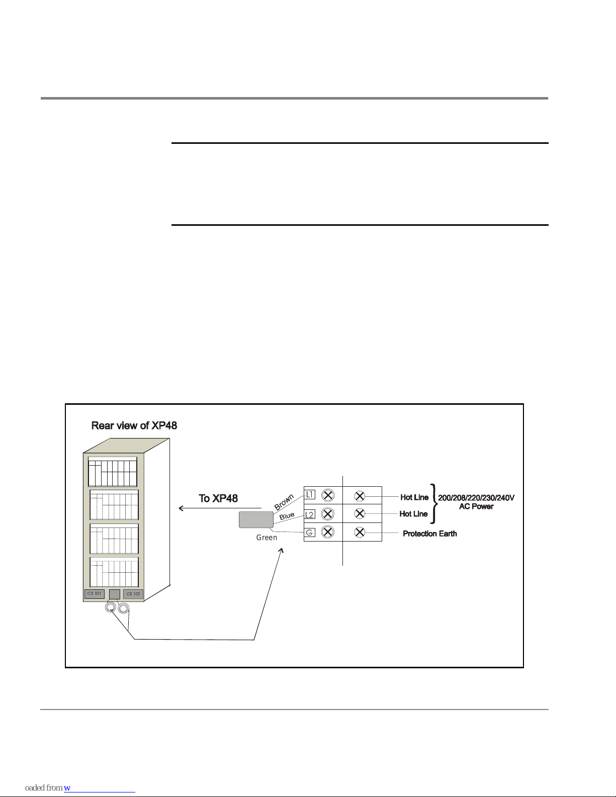
Single-Phase Cabling for Europe
Caution The HP SureStore E Disk Array XP48 has two main disconnect devices
(two main Breaker CB101 for dual power lines) so that AC power of the
unit can be supplied from the separate power distribution board with two
power supply cords.
before connecting the equipment to the power source.
Connecting the Power Supply Cord
The unit has two powe r supply cords. The power cord included with th e
unit is a type H07RN-F or equivalent, with five 2.5 mm
Be sure to connect a power cord to the distribution box as illustrated in the
figure below. To reduce the risk of a wrong connection, use a socket
approved for this disk array.
Observe all instructions described in this manual
2
conductors.
/
/
*
Y
/
e
l
l
o
w
&%
&%
G
e
e
r
n
42 HP SureStore E Disk Array 48: Site Prep Guide
Page 43

High leakage curr ent may occur between the power supply and the unit. T o
avoid an electrica l shock, be sure t o perform the pro tective eart h connection
before the supply connections are made.
Branch Circuit Requirements
To protect your disk array, your building must be wired correc tly. Each line
(U/L1, V/L2 line) should be protected by a short circuit protective device
and by an overcurrent protective device rated 20 amp on building
installation.
The protective devi ce on buildi ng inst allat ion sho uld compl y with Na tiona l
Standards of the country where the units shall be installed, and if a
protective device interrupts a conductor, it shall also interrupt all other
supply conductors.
Preparing for Installation 43
Page 44

Environmental Requirements
The environmental specification for operating your disk array must be
satisfied prior to installation.
Air Conditioning Ducts
Use separate computer room air co nditioni ng duct work. I f it is no t separate
from the rest of the building, it might be difficult to control cooling and air
pressure levels. Duct work seals are important for maintaining a balance d
air conditioning system and high static air pressure. Adequate cooling
capacity means little if the direction Humidity levels may increase if the
ducts are exposed to warm air.
Humidity
Maintain proper humidity levels. High humidity levels causes galvanic
actions t o occur between some dissimilar metals. This e ventually causes a
high resistance between connections, leading to equipment failure.
Caution Low humidity contributes to undesi rably high levels of electrostatic
char ges. Th is i ncreases the electrostatic dischar ge (ESD) volt age po tenti al.
ESD can cause component damage during servicing operations.
Static charges (voltage levels) occur when objects are separated or rubbed
together. The voltage level of a static charge is determined by the following
factors:
• types of materials
• relative humidity
• rate of change or separation
44 HP SureStore E Disk Array 48: Site Prep Guide
Page 45

Follow these precautions to minimize possible ESD-induced failures in
your computer room:
• Install conductive flooring (conductive adhesive must be used when
laying tiles).
• Use conductive wax if waxed floors are installed.
• Ensure that all equi pment and fl oorin g are prope rly g rounded an d ar at
the same ground potential.
• Use conductive tables and chairs.
• Store spare electric par t s in antista tic containers.
• Maintain recommended humidity level an airflow rates.
Low humi dity levels are often th e result of th e facility heating system and
occur during the cold season. Most heating systems provide air with a low
humidity level, unless the system has a built-in humidifier.
Dust and Pollution Control
For troublefree operation, disk drives require a dust-free environment, The
HP SureStore E Disk Array XP48 disk drive is protected from dust particles
by mechan ical air filters designed to trap large d ust particl es. Smaller
particles can pass through some filters, and, over a period of time, can
cause problems in mechanical parts. Small dust particles can be prevented
from entering the computer room by maintaining its air conditioning
system at a high static air pressure level.
HP SureStore E Disk Array XP48 Temperature and Humidity
Specifications
When the disk array is operating, the recommended temperature range is
21°C to 24°C and recommended relative humidity range to be (at 22
between 50 to 55 percent. The following table lists the temperature,
humidity, and vibration specifications for the HP SureStore E Disk Array
XP48. The vibration and shock specifications apply to all three axes.
° C)
Preparing for Installation 45
Page 46

Caution No condensation in and around the HP SureStore E Disk Array XP48
should be observed under any conditions.
Shipping and
Specification Operating
1
Nonoperating
2
Storage
3
Temperature (°C) 16 ~ 32 -10 ~ 43 - 25 ~ 60
Relative humidity
4
(%)
20 ~ 80 8 ~ 90 5 ~ 95
Max wet bulb (°C) 26 27 29
T emperature
10 10 20
deviation (°C/
hour)
Vibration
5
0.25mm,
5 ~ 10Hz
0.05G,
10-300Hz
2.5mm,
5 ~ 10 Hz
0.5G,
10 ~ 70 Hz
0.05mm,
0.5G, 15 min.
At four most
severe resonanc e
between
5~200Hz
6
70 ~ 99 Hz
1.0G,
99 ~ 300 Hz
Shock 8G, 15ms
Horizontal:
7
incline
impact:1.22m/s
1. Environmental specification for operating condition should be
satisfied before the disk subsystem is powere d on. Max. temperature
of 32ºC should be strictly satisfied at the air inlet portion. The
recommen ded temperature range is 21~24ºC.
46 HP SureStore E Disk Array 48: Site Prep Guide
Vertical:
8
rotational e dge:
0.15m
Page 47

2. Nonoperating condition includes both packing and unpacking
conditions unless otherwise specified.
3. On shipping/storage condition, the product should be packed with
factory packing.
4. No condensation in and around the drive should be observed under
any conditions.
5. The specifications apply to all three axes
6. See ASTM D999-86 Standard Methods for Vibration Testing of
Shipping Containers
7. See ASTM D880-86 Standard Methods of Incline Impact Test for
Shipping Containers
8. See ASTM D775-80 Standard Methods for Drop Test for Loaded
Boxes.
Preparing for Installation 47
Page 48

Heat Dissipation
The following table describes the heat dissipation of the XP48 (fully
loaded):
Heat Dissipation
Power consumption (kVA) 3.34
Heat dissipation (kW) 3.10
BTUs per hour 10,571
kcal per hour 2,666
48 HP SureStore E Disk Array 48: Site Prep Guide
Page 49

Altitude
When operating the HP SureStore E Disk Array XP48, the maximum
altitude is 3,000 meters. Nonoperational, the maximum altitude is 4,000
meters.
Preparing for Installation 49
Page 50

Acoustics
Computer equipment and air conditioning blowers cause computer rooms
to be noisy. Ambient noise level in a computer room can be reduced as
follows:
dropped ceiling Cover with a commercial-grade fire-resistant, acousti c
rated, fiberglass ceiling tile.
sound deadening Cover the walls with sound-deadening materi al.
removable partitions
To be most effective, use foam rubber models.
acoustic emissions
7.3 Bels (A) sound power
58.5 dB (A) sound pressure, operator position
50 HP SureStore E Disk Array 48: Site Prep Guide
Page 51

Delivery Space Requirements
There should be enough clearance to move equipment safely from the
receiving area to the computer room. Permanent obstruct ions, such as
pillars or narrow doorways, can cause equipment damage.
Delivery plans should include the possible removal of walls or doors. the
physical dimensions were summarized on page 25.
Preparing for Installation 51
Page 52

52 HP SureStore E Disk Array 48: Site Prep Guide
Page 53

UPON RECEIPT OF YOUR HP
SURESTORE E DISK ARRAY XP48
Your HP SureStore E Disk Array XP4 8 is sh ipped d irect ly fr om HP. If your
disk array is part of a system order, HP coordinates the shipment of
equipment from all locations so that it arrives at your site at approximately
the same time.
In some cases, factors beyond the control of HP can cause delivery delays.
If you have not received your equipment within a two week period, notify
your HP sales representative. The HP sales representative will trace your
order and expedite delivery.
Caution Be sure to allow for size and weight in regards to placing the disk array at
its installation site. Refer to “Physical Requirements” (page 23) for
specific size and weight values.
53
Page 54

Checking for Shipping Shortage and Damage
As your disk array arrives, check the carrier’s bill of lading carefully to
ensure that all items sh ipped by HP are deliver ed. Notify the carrier
immediately if ther e are any discrepancies or items missing.
Inspect all of the shipping containers for signs of damage before actually
unpacking the equi pment. Some typ ical signs of shipping damage are dents,
scratches, cuts, or water marks. If any damage is found, note on the bill of
lading that there is apparent dama ge subject to inspection. Arrange for the
carrier’s representative and a representative from Hewlett-Packard to be
present when the item in question is unpacked.
Regardless of the cir cumstances, the HP CE w ill take immediate action to
replace any damaged components without waiting for the settlement of
claims.
54 HP SureStore E Disk Array XP48 Site Prep Guide
Page 55

Unpacking the Cartons
The equipment cartons can be unpacked at your convenience; it is your
responsibility to have the equipment unpacked and moved to its proper
installation location prior to the day of installation.
Leave the packing list (invoice) for each carton that is to be unpacked and
ensure that each item on the list can be accounted for. Contact your HP
sales representative immediately if there are any missing items, or if the
items are not the same as you ordered.
Leave the sealed cartons of CDs, cables, and any other installation
hardware intact for t he HP CE. Your HP CE and HP ASE will install and
configure your disk array.
Upon Receipt of Your HP SureStore E Disk Array XP48 55
Page 56

56 HP SureStore E Disk Array XP48 Site Prep Guide
Page 57

PRELIMINARY
INDEX
A
acoustics
XP512 50
altitude
XP512 49
application software engineer (ASE)
site preparation team 12
C
clearance
XP512 service 29
computer room
XP512 requirements 19
customer
site preparation responsibilities 13
customer engineer (CE)
site preparation team 12
D
damage, shipping
XP512 54
data communications
XP512 requirements 31
delivery
XP512 51
dimensions
XP512 23
E
electrical interference
sources of 38
electrical requirements
XP512 34
environmental requirements
XP512 44
F
floor
XP512 load 29
H
hardware
disk control frame 20
major hardware components 21
remote con sole 21
service processor 20
heat dissipation
XP512 48
I
installation
XP512 17, 53
57
Page 58

M
major hardware components
disk control frame 20
remote con sole 21
service processor 20
P
physical components
major hardware components 21
power cord
single-phase (Europe) 42
single-phase AC (USA) 40
S
safety
XP512 18
sales representative ( SR)
site preparation team 12
site preparation
checklist 14
physical requirements 23
preparations before delivery 16
team 12
PRELIMINARY
W
weight
XP512 25
X
XP512
unpacking 55
58 HP SureStore E Disk Array XP48: Site Prep Guide
Page 59

Reader Comment Sheet
PRELIMINARY
HP SureStore E Disk Array XP48
Site Prep Guide
We welcome your evaluation of this manual. Your comments and suggestions will help us improve our publications. Remove
this page and mail or FAX it to 916-785-2299. Use and attach additional pages if necessary.
Agree Disagree N/A
The manual is well organized.
The information is technically accurate.
Information is easy to find.
Step-by-step procedures are easy to perform.
There are enough examples and pictures.
The examples and pictures are useful.
Comments_________________________________________________________________________________
________________________________________________________________________________
________________________________________________________________________________
________________________________________________________________________________
Name: Phone:
Title: FAX:
Company: E-mail:
Address: ZIP:
City & State: Country:
___ Check here if you would like a reply.
Hewlett-Packard has the right to use submitted suggestio ns witho ut obliga tion, with all such ideas becoming the property of Hewlett-Packard.
XPSO Roseville Information E ngineering E1100 P/NA5921-96000
Page 60
Please Do Not Staple
BUSINESS REPLY MAIL
FIRST CLASS MAIL PERMIT NO. 256 ROSEVILLE, CA
POSTAGE WILL BE PAID BY ADDRESSEE
Attention: Information Engineering (MS 5668)
HPSO
Hewlett-Packard Company
8000 Foothills Blvd.
Roseville, CA 95747-9987
NO POSTAGE
NECESSARY
IF MAILED
IN THE
UNITED STATES
Fold Here
Tape Please Do Not Staple Tape
 Loading...