

Page 1

Hewlett-Packard
SureStore E Hub
Models S10 and L10
Service and
User Manual
Page 2

Page 3

Hewlett-Packard SureStore E Hub
Models S10 and L10
Service and User Manual
Edition E0899
Order No. A3724-90006
Printed in U.S.A.
Page 4

2
Notice
© Hewlett-Packard Company, 1997, 1998, 1999.
All rights reserved.
Hewlett-Packard Company makes no warranty of
any kind with regard to this material, including, but
not limited to, the implied warranties of
merchantability and fitness for a particular purpose.
Hewlett-Packard shall not be liable for errors
contained herein or for incidental or consequential
damages in connection with the furnishing,
performance, or use of this material.
This document contains proprietary information,
which is protected by copyright. No part of this
document may be photocopied, reproduced, or
translated into another language without the prior
written consent of Hewlett-Packard. The
information contained in this document is subject to
change without notice.
Warranty
If you have any questions about the warranty for
this product, contact your dealer or local HewlettPackard sales representative.
Trademark Information
HyperTerminal is a registered trademark of
Hilgreave, Inc.
Windows and Windows NT are either a registered
trademark or trademark of Microsoft Corporation in
the United States and/or other countries.
Safety Instructions
Grounding
This product is a safety class I product and has a
protective earthing terminal. There must be an
uninterruptible safety earth ground from the main
power source to the product’s input wiring
terminals, power cord, or supplied power cord set.
Whenever it is likely that the protection has been
impaired, disconnect the power cord until the
ground has been restored.
Service
Any servicing, adjustment, maintenance, or repair
must be performed only by authorized servicetrained personnel.
Format Conventions
Denotes
WARNING A hazard that can cause
personal injury
Caution A hazard that can cause hardware
or software damage
Note Significant concepts or operating
instructions
this font Text to be typed verbatim: all
commands, path names, file
names, and directory names
this font Text displayed on the screen
<ENTER> Keys to be pressed, for example,
the <ENTER> key
Page 5

3
CONTENTS
Contents
1 Product Description. . . . . . . . . . . . . . . . . . . . . . . . . . . . . . . . . . . . . . . . . . . . . . 11
Overview . . . . . . . . . . . . . . . . . . . . . . . . . . . . . . . . . . . . . . . . . . . . . . . . . . . . . . . . . . . . .12
Features . . . . . . . . . . . . . . . . . . . . . . . . . . . . . . . . . . . . . . . . . . . . . . . . . . . . . . . . . . . . . . 13
Front Panel, Model S10 Short-Wave Hub. . . . . . . . . . . . . . . . . . . . . . . . . . . . . . . . . . . 14
Front Panel, Model L10 Long-Wave Hub . . . . . . . . . . . . . . . . . . . . . . . . . . . . . . . . . . . 15
Rear Panel, Short-Wave and Long-Wave Hubs . . . . . . . . . . . . . . . . . . . . . . . . . . . . . . 16
Supported Topologies . . . . . . . . . . . . . . . . . . . . . . . . . . . . . . . . . . . . . . . . . . . . . . . . . . 17
Single Short-Wave Hub Topology . . . . . . . . . . . . . . . . . . . . . . . . . . . . . . . . . . . . . . 17
Cascaded Short-Wave Hub Topology . . . . . . . . . . . . . . . . . . . . . . . . . . . . . . . . . . .18
Cascaded Long-Wave Hub Topology . . . . . . . . . . . . . . . . . . . . . . . . . . . . . . . . . . . 19
2 Installation. . . . . . . . . . . . . . . . . . . . . . . . . . . . . . . . . . . . . . . . . . . . . . . . . . . . . . . . . . 21
Overview . . . . . . . . . . . . . . . . . . . . . . . . . . . . . . . . . . . . . . . . . . . . . . . . . . . . . . . . . . . . .22
Procedure 1: Prepare to Install the Hub. . . . . . . . . . . . . . . . . . . . . . . . . . . . . . . . . . . .23
Procedure 2: Unpack the Hub . . . . . . . . . . . . . . . . . . . . . . . . . . . . . . . . . . . . . . . . . . . .24
Procedure 3: Verify Hub Operation . . . . . . . . . . . . . . . . . . . . . . . . . . . . . . . . . . . . . . .25
Procedure 4: Mount the Hub into a Rack (Optional) . . . . . . . . . . . . . . . . . . . . . . . . . 27
Procedure 5: Plan the FC-AL Connections . . . . . . . . . . . . . . . . . . . . . . . . . . . . . . . . .32
Correct Cabling Example for a Short-Wave Hub . . . . . . . . . . . . . . . . . . . . . . . . .32
Correct Cabling Example for a Long-Wave Hub . . . . . . . . . . . . . . . . . . . . . . . . . .33
Incorrect Cabling Examples . . . . . . . . . . . . . . . . . . . . . . . . . . . . . . . . . . . . . . . . . . 35
Nonsupported Cabling Example . . . . . . . . . . . . . . . . . . . . . . . . . . . . . . . . . . . . . . . 37
Procedure 6: Connect FC-AL Devices . . . . . . . . . . . . . . . . . . . . . . . . . . . . . . . . . . . . . 38
Procedure 7: Verify the Connections . . . . . . . . . . . . . . . . . . . . . . . . . . . . . . . . . . . . . . 40
Page 6

4
For HP-UX servers: . . . . . . . . . . . . . . . . . . . . . . . . . . . . . . . . . . . . . . . . . . . . . . . . . .40
For HP NetServers: . . . . . . . . . . . . . . . . . . . . . . . . . . . . . . . . . . . . . . . . . . . . . . . . . . 40
3 RS-232 Interface Functions . . . . . . . . . . . . . . . . . . . . . . . . . . . . . . . . . . . . 41
Overview . . . . . . . . . . . . . . . . . . . . . . . . . . . . . . . . . . . . . . . . . . . . . . . . . . . . . . . . . . . . . 42
About the RS-232 Main Menu . . . . . . . . . . . . . . . . . . . . . . . . . . . . . . . . . . . . . . . . . 43
Tips for Using the RS-232 Interface . . . . . . . . . . . . . . . . . . . . . . . . . . . . . . . . . . . . 44
Setting Up an RS-232 Connection . . . . . . . . . . . . . . . . . . . . . . . . . . . . . . . . . . . . . . . . . 45
Setting Up a Connection to a PC. . . . . . . . . . . . . . . . . . . . . . . . . . . . . . . . . . . . . . . 45
Setting Up a Connection to a Dumb Terminal . . . . . . . . . . . . . . . . . . . . . . . . . . . 46
Updating the Hub Firmware . . . . . . . . . . . . . . . . . . . . . . . . . . . . . . . . . . . . . . . . . . . . . 48
Procedure 1: Obtain the Current Firmware. . . . . . . . . . . . . . . . . . . . . . . . . . . . . . 49
Procedure 2: Reboot the Hub . . . . . . . . . . . . . . . . . . . . . . . . . . . . . . . . . . . . . . . . .49
Procedure 3: Update the Hub Controller Firmware . . . . . . . . . . . . . . . . . . . . . . . 50
Procedure 4: Update the Hub Device Agent Code . . . . . . . . . . . . . . . . . . . . . . . . 52
Procedure 5: Reset the Hub . . . . . . . . . . . . . . . . . . . . . . . . . . . . . . . . . . . . . . . . . . . 53
Procedure 6: Set Manufacturing Values . . . . . . . . . . . . . . . . . . . . . . . . . . . . . . . . . 54
Enabling Hub Management . . . . . . . . . . . . . . . . . . . . . . . . . . . . . . . . . . . . . . . . . . . . . . 57
Setting Hub IP Address and Network Configuration Options. . . . . . . . . . . . . . . 57
Verifying and Setting SNMP Values . . . . . . . . . . . . . . . . . . . . . . . . . . . . . . . . . . . .58
Configuring Cascaded Hubs . . . . . . . . . . . . . . . . . . . . . . . . . . . . . . . . . . . . . . . . . . 60
Running Diagnostic Tests . . . . . . . . . . . . . . . . . . . . . . . . . . . . . . . . . . . . . . . . . . . . . . . 64
Viewing Hub Information. . . . . . . . . . . . . . . . . . . . . . . . . . . . . . . . . . . . . . . . . . . . . . . . 65
4 Troubleshooting . . . . . . . . . . . . . . . . . . . . . . . . . . . . . . . . . . . . . . . . . . . . . . . . . . 67
Troubleshooting Procedures. . . . . . . . . . . . . . . . . . . . . . . . . . . . . . . . . . . . . . . . . . . . . 68
LED Indicators . . . . . . . . . . . . . . . . . . . . . . . . . . . . . . . . . . . . . . . . . . . . . . . . . . . . . . . . 70
Page 7

5
Contents
If the Power LED Is Off . . . . . . . . . . . . . . . . . . . . . . . . . . . . . . . . . . . . . . . . . . . . . . . . . 72
If the Hub Fault LED Stays on After Self-Test. . . . . . . . . . . . . . . . . . . . . . . . . . . . . . . 73
If a Fan Is Not Operating . . . . . . . . . . . . . . . . . . . . . . . . . . . . . . . . . . . . . . . . . . . . . . . . 74
If a Device Is Unlisted/UNCLAIMED in ioscan or
Not Displayed in SCSI Adapters Window . . . . . . . . . . . . . . . . . . . . . . . . . . . . . . . . . .75
If a Port LED Is Off . . . . . . . . . . . . . . . . . . . . . . . . . . . . . . . . . . . . . . . . . . . . . . . . . . . . .76
If a Port LED Is On When It Should Be Off . . . . . . . . . . . . . . . . . . . . . . . . . . . . . . . . .77
If the Management Server Cannot Ping the Hub. . . . . . . . . . . . . . . . . . . . . . . . . . . . . 78
If Firmware Upgrade Appears to Fail. . . . . . . . . . . . . . . . . . . . . . . . . . . . . . . . . . . . . . 79
Recovering from Failed Firmware Upgrade . . . . . . . . . . . . . . . . . . . . . . . . . . . . . 80
5 Maintenance and Replacement. . . . . . . . . . . . . . . . . . . . . . . . . . . . . . . . 85
Introduction . . . . . . . . . . . . . . . . . . . . . . . . . . . . . . . . . . . . . . . . . . . . . . . . . . . . . . . . . . .86
Maintenance. . . . . . . . . . . . . . . . . . . . . . . . . . . . . . . . . . . . . . . . . . . . . . . . . . . . . . . . . . . 87
Replacing the Fan Module . . . . . . . . . . . . . . . . . . . . . . . . . . . . . . . . . . . . . . . . . . . . . . .88
6 Reference . . . . . . . . . . . . . . . . . . . . . . . . . . . . . . . . . . . . . . . . . . . . . . . . . . . . . . . . . . . 91
Standard Configurations . . . . . . . . . . . . . . . . . . . . . . . . . . . . . . . . . . . . . . . . . . . . . . . . 92
Configuration Options . . . . . . . . . . . . . . . . . . . . . . . . . . . . . . . . . . . . . . . . . . . . . . . . . . 95
Replacement Parts . . . . . . . . . . . . . . . . . . . . . . . . . . . . . . . . . . . . . . . . . . . . . . . . . . . . . 97
Operating Requirements . . . . . . . . . . . . . . . . . . . . . . . . . . . . . . . . . . . . . . . . . . . . . . . 100
Software and Operating System Requirements. . . . . . . . . . . . . . . . . . . . . . . . . . 100
Physical and Cabling Requirements . . . . . . . . . . . . . . . . . . . . . . . . . . . . . . . . . . . 100
Supported Hardware. . . . . . . . . . . . . . . . . . . . . . . . . . . . . . . . . . . . . . . . . . . . . . . . 103
Supported Distances. . . . . . . . . . . . . . . . . . . . . . . . . . . . . . . . . . . . . . . . . . . . . . . . 104
Environmental Specifications . . . . . . . . . . . . . . . . . . . . . . . . . . . . . . . . . . . . . . . . . . . 107
Physical Characteristics of Standalone Hub . . . . . . . . . . . . . . . . . . . . . . . . . . . . . . . 108
Reference Documents . . . . . . . . . . . . . . . . . . . . . . . . . . . . . . . . . . . . . . . . . . . . . . . . .109
Page 8

6
Regulatory Statements . . . . . . . . . . . . . . . . . . . . . . . . . . . . . . . . . . . . . . . . . . . . . . . . . 110
Laser Safety . . . . . . . . . . . . . . . . . . . . . . . . . . . . . . . . . . . . . . . . . . . . . . . . . . . . . . . . . . 113
Glossary. . . . . . . . . . . . . . . . . . . . . . . . . . . . . . . . . . . . . . . . . . . . . . . . . . . . . . . . . . . . 117
Index . . . . . . . . . . . . . . . . . . . . . . . . . . . . . . . . . . . . . . . . . . . . . . . . . . . . . . . . . . . . . . . . 121
Page 9

7
FIGURES
Figures
1 Front Panel Display, Short-Wave Hub . . . . . . . . . . . . . . . . . . . . . . . . . . . . . . . . . . . . . . . .14
2 Front Panel Display, Long-Wave Hub . . . . . . . . . . . . . . . . . . . . . . . . . . . . . . . . . . . . . . . . .15
3 Rear Panel . . . . . . . . . . . . . . . . . . . . . . . . . . . . . . . . . . . . . . . . . . . . . . . . . . . . . . . . . . . . . . . .16
4 Example Topology: 10 Ports Shared among Server and FC-AL Devices . . . . . . . . . . . . . 17
5 Example Topology: Cascaded Short-Wave Hubs . . . . . . . . . . . . . . . . . . . . . . . . . . . . . . . . 18
6 Example Topology: Cascaded Long-Wave Hubs . . . . . . . . . . . . . . . . . . . . . . . . . . . . . . . .19
7 Standalone Product Contents . . . . . . . . . . . . . . . . . . . . . . . . . . . . . . . . . . . . . . . . . . . . . . . .24
8 Replacing Mounting Ear Brackets and Nylon Retainers . . . . . . . . . . . . . . . . . . . . . . . . . .27
9 Installing Rails . . . . . . . . . . . . . . . . . . . . . . . . . . . . . . . . . . . . . . . . . . . . . . . . . . . . . . . . . . . . . 28
10 Installing the Hub into the Rack . . . . . . . . . . . . . . . . . . . . . . . . . . . . . . . . . . . . . . . . . . . . . .29
11 Installing the Plenum Shroud . . . . . . . . . . . . . . . . . . . . . . . . . . . . . . . . . . . . . . . . . . . . . . . . 30
12 Hub Correctly Installed in a Rack . . . . . . . . . . . . . . . . . . . . . . . . . . . . . . . . . . . . . . . . . . . . . 31
13 Cascaded Short-Wave Hub Configuration . . . . . . . . . . . . . . . . . . . . . . . . . . . . . . . . . . . . . . 33
14 Cascaded Long-Wave Hub Configuration . . . . . . . . . . . . . . . . . . . . . . . . . . . . . . . . . . . . . . 34
15 Incorrect Cabling Example: Connected Ports on the Same Hub . . . . . . . . . . . . . . . . . . .35
16 Incorrect Cabling Example: Disconnected Cable . . . . . . . . . . . . . . . . . . . . . . . . . . . . . . . . 35
17 Incorrect Cabling Example: More Than One Cable Connection Between Hubs . . . . . . 36
18 Incorrect Cabling Example: Long-Wave Port Connections to Wrong Device/Port . . . . 36
19 Nonsupported Cabling Example: More Than Two Hubs Connected . . . . . . . . . . . . . . . 37
20 Nonsupported Cabling Example: HP-UX Server and HP NetServer
Connected to Same Hub . . . . . . . . . . . . . . . . . . . . . . . . . . . . . . . . . . . . . . . . . . . . . . . . . . . .37
21 Removing the Fan Module . . . . . . . . . . . . . . . . . . . . . . . . . . . . . . . . . . . . . . . . . . . . . . . . . . 89
22 Replacing the Fan Module . . . . . . . . . . . . . . . . . . . . . . . . . . . . . . . . . . . . . . . . . . . . . . . . . . . 90
Page 10

8
23 HP SureStore E Hub, Standalone . . . . . . . . . . . . . . . . . . . . . . . . . . . . . . . . . . . . . . . . . . . . . 93
24 HP SureStore E Hub, Factory-Racked . . . . . . . . . . . . . . . . . . . . . . . . . . . . . . . . . . . . . . . . . 94
25 Model S10 or L10 Option 001 Hub Rackmount Kit . . . . . . . . . . . . . . . . . . . . . . . . . . . . . . . 96
26 HP SureStore E Hub Replaceable Parts . . . . . . . . . . . . . . . . . . . . . . . . . . . . . . . . . . . . . . . . 97
Page 11

9
TABLES
Tables
1 Worksheet for Hub Configuration . . . . . . . . . . . . . . . . . . . . . . . . . . . . . . . . . . . . . . . . . . . .42
2 LED Indications . . . . . . . . . . . . . . . . . . . . . . . . . . . . . . . . . . . . . . . . . . . . . . . . . . . . . . . . . . . 70
3 HP SureStore E Hub Product Numbers . . . . . . . . . . . . . . . . . . . . . . . . . . . . . . . . . . . . . . . . 92
4 HP SureStoreE Hub Configuration Options . . . . . . . . . . . . . . . . . . . . . . . . . . . . . . . . . . . . . 95
5 HP SureStore E Hub Replaceable Parts and Service Part Numbers . . . . . . . . . . . . . . . .98
6 Multimode Fiber Optic Cable Part Numbers . . . . . . . . . . . . . . . . . . . . . . . . . . . . . . . . . . . . 98
7 Power Cord Part Numbers . . . . . . . . . . . . . . . . . . . . . . . . . . . . . . . . . . . . . . . . . . . . . . . . . . .99
8 Cable Plant Specifications: Single-Mode (2 km–10km, 100MB/sec) . . . . . . . . . . . . . . .101
9 Cable Plant Specifications: 50-Micron Multimode (500m, 100MB/sec)
Non-OFC Operation. . . . . . . . . . . . . . . . . . . . . . . . . . . . . . . . . . . . . . . . . . . . . . . . . . . . . . . . 102
10 Cable Plant Specifications: 62.5-Micron Multimode (175m, 100MB/sec)
Non-OFC Operation. . . . . . . . . . . . . . . . . . . . . . . . . . . . . . . . . . . . . . . . . . . . . . . . . . . . . . . . 102
11 Supported Cable Distances . . . . . . . . . . . . . . . . . . . . . . . . . . . . . . . . . . . . . . . . . . . . . . . . .104
12 Environmental Specifications for Model S10 Short-Wave and
Model L10 Long-Wave Hubs . . . . . . . . . . . . . . . . . . . . . . . . . . . . . . . . . . . . . . . . . . . . . . . . . 107
13 Physical Characteristics of Model S10 Short-Wave and Model L10 Long-Wave Hubs . 108
Page 12

10
Page 13

Product Description
11
1 PRODUCT DESCRIPTION
Overview
Features
Front Panel, Model S10 Short-Wave Hub
Front Panel, Model L10 Long-Wave Hub
Rear Panel, Short-Wave and Long-Wave Hubs
Supported Topologies
Page 14

12 Overview
Overview
The Hewlett-Packard SureStore E hub, short-wave model S10 and long-wave model L10, is
a full-duplex, 1063-megabit-per-second hub. It increases loop reliability, number of loop
connections, and distances between server and mass storage devices in a Fibre Channel
Arbitrated Loop. The hub’s port detection and bypass circuitry dynamically detects and
bypasses a failed node on the loop. Nodes can be added, removed, and reconnected
without bringing down the loop and disrupting communication for other nodes.
Fibre Channel Manager is a web-based software application that allows you to remotely
manage and monitor the health of the hub. To learn more about Fibre Channel Manager,
visit the Hewlett-Packard (Software Depot (http://www.software.hp.com). Fibre Channel
Manager is available as a free download from this web site.
Older hubs may require a firmware upgrade to meet Fibre Channel Manager’s minimum
requirements. The Software Depot web site has more information about this. The latest
hub firmware and upgrade instructions are available as a free download from this web site.
Detailed configuration information and part numbers for the hub are provided in chapter6,
Reference.
Page 15

Features 13
Product Description
Features
HP SureStore E hubs provide the following features:
• Short-wave hub (model S10): 10 non-Open Fibre Control (non-OFC) short-wave
optical transceivers
• Long-wave hub (model L10): nine non-OFC, short-wave optical transceivers and one
non-OFC, long-wave optical transceiver
• Local retime and regeneration of transmit signals to prevent accumulation of jitter and
improve the signal
• Reliable, automatic bypass of failed nodes; dynamic recognition of newly added or
removed nodes, with a controller in each port permitting the bypass of a port if the port
fails signal validity tests
• Active loop reconfiguration when a node to an arbitrated loop is added, removed, or
moved
• Plug-and-play capability, which allows the hub to connect to compatible servers and
other Fibre Channel Arbitrated Loop (FC-AL) devices while they are operating ( FC-AL
devices can be added or removed while the hub is active.)
• Cascade support (hub-to-hub connections) for increased loop distances
Cascaded short-wave hubs are supported up to 500 meters; cascaded long-wave hubs
are supported up to 3000 meters (3 km). Under certain conditions, cascaded long-wave
hubs are supported up to 10,000 meters (10 km) (see page105 for more information).
The 10-km capability only applies to long-wave hubs connected to HP-UX servers.
Note Increased loop distances are associated with increased latency times.
• Access to the RS-232 interface for firmware upgrades and hub configuration and
troubleshooting
• Support for a hub management tool (Fibre Channel Manager) to remotely manage and
monitor the health of the hub
Page 16
14 Front Panel, Model S10 Short-Wave Hub
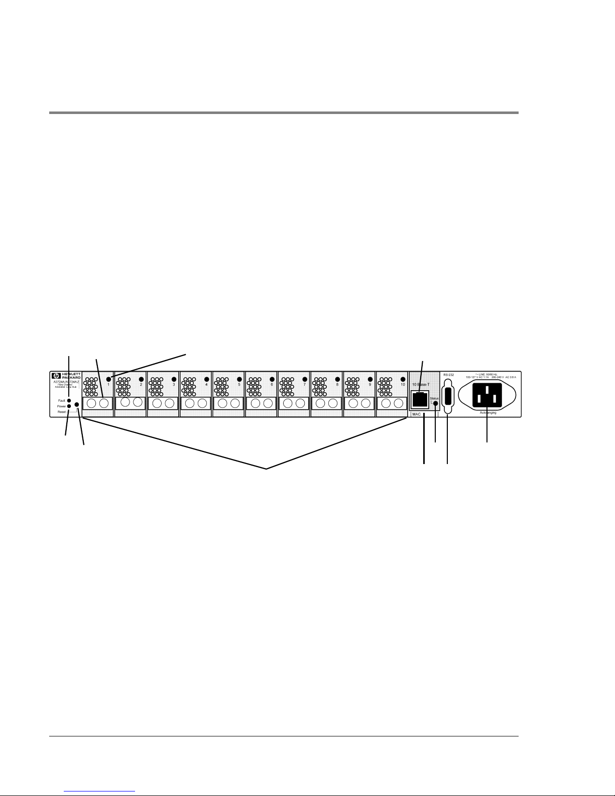
Front Panel, Model S10 Short-Wave Hub
The front panel contains LEDs for monitoring power, fault, and port status. The RS-232
port is provided to configure and troubleshoot the hub and to upgrade its firmware. The
10Base-T port provides an ethernet connection if you choose to manage the hub with Fibre
Channel Manager.
The Reset button resets the internal control microprocessor of the hub. Pushing the Reset
button also forces loop initialization on all devices in the loop.
Figure 1 Front Panel Display, Short-Wave Hub
1 Power LED 7 10Base-T port
2 Fault LED 8 10Base-T Status LED
3 Reset button 9 MAC address
4 Fibre Channel connector (Port 1 indicated) 10 RS-232 port
5 Port LED (Port 1 indicated) 11 AC power connector
6 FC-AL short-wave ports and Port LEDs
1
3
2
4
5
6
7
10
11
9
8
Page 17
Front Panel, Model L10 Long-Wave Hub 15
Product Description
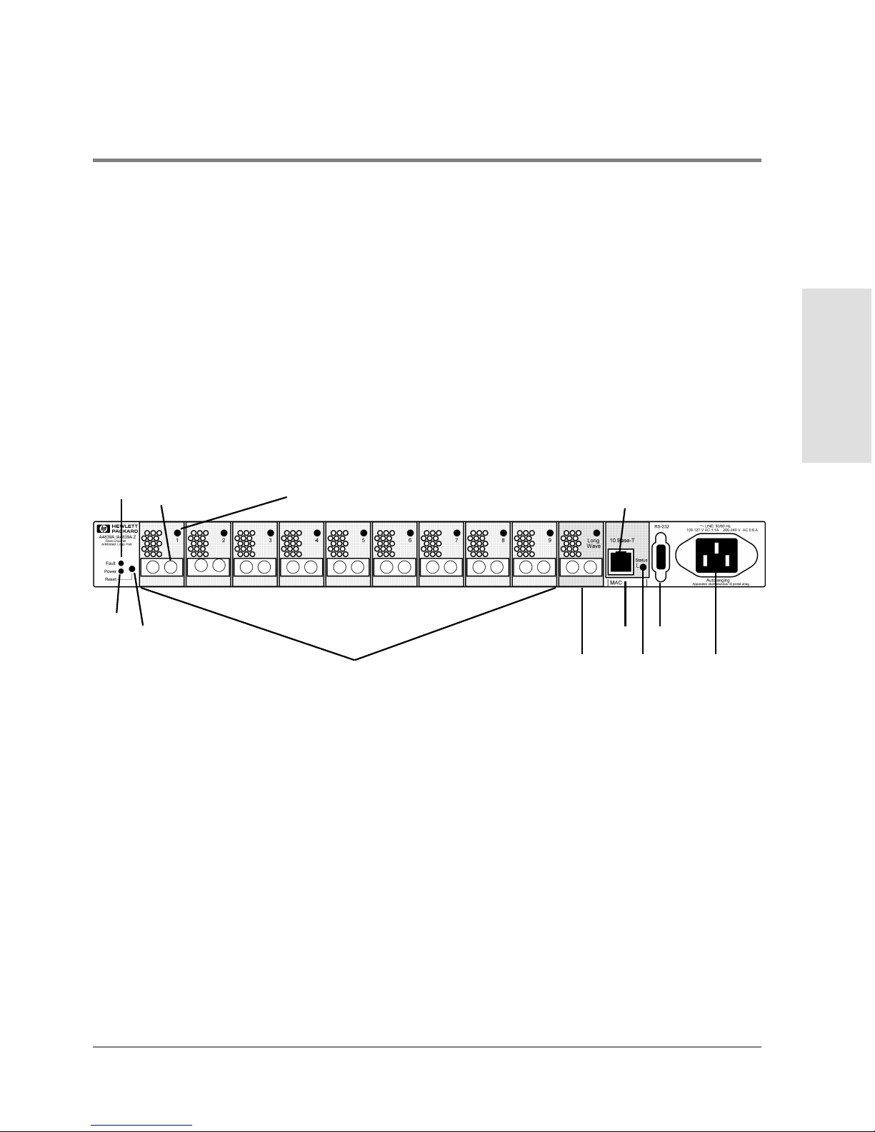
Front Panel, Model L10 Long-Wave Hub
The front panel contains LEDs for monitoring power, fault, and port status. The long-wave
port is between port 9 and the 10Base-T port. The RS-232 port is provided to configure and
troubleshoot the hub and to upgrade its firmware. The 10Base-T port provides an ethernet
connection if you choose to manage the hub with Fibre Channel Manager.
The Reset button resets the internal control microprocessor of the hub. Pushing the Reset
button also forces loop initialization on all devices in the loop.
Figure 2 Front Panel Display, Long-Wave Hub
1 Power LED 7 FC-AL long-wave port and Port LED
2 Fault LED 8 10Base-T port
3 Reset button 9 10Base-T Status LED
4 Fibre Channel connector (Port 1 indicated) 10 MAC address
5 Port LED (Port 1 indicated) 11 RS-232 port
6 FC-AL short-wave ports and Port LEDs 12 AC power connector
1
2
3
4
6
8
10
11
12
5
7
9
Page 18
16 Rear Panel, Short-Wave and Long-Wave Hubs
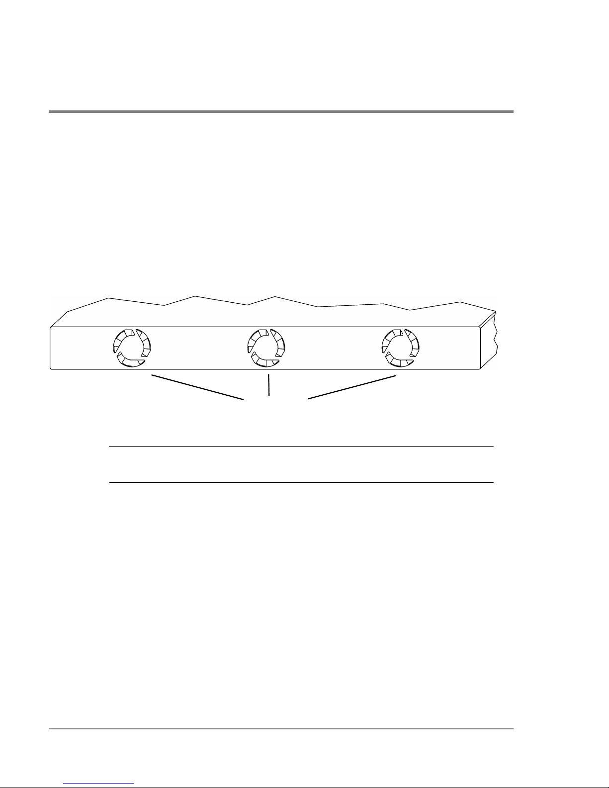
Rear Panel, Short-Wave and Long-Wave Hubs
Three fans, located in a customer-replaceable module at the rear panel, cool the hub. If one
fan fails, the remaining two fans cool the hub temporarily, but it is important to replace the
module as soon as possible (see chapter5, Maintenance and Replacement).
Figure 3 Rear Panel
Caution Although the module will continue to run with two fans, a full complement of
fans ensures system and data integrity.
fan air vents
Page 19
Supported Topologies 17
Product Description
Supported Topologies
Devices such as FC-AL disk arrays and HP system servers that support FC-AL can be
connected to the hub in a loop that includes one or more servers. All nodes in the loop
must be 1063 Mbps short-wave, non-OFC, FC-AL. The ports connected by a cable must
have the same optical transceivers. Figure4, Figure5, and Figure6 show typical hub
topologies. For details on supported topologies, contact an HP sales representative.
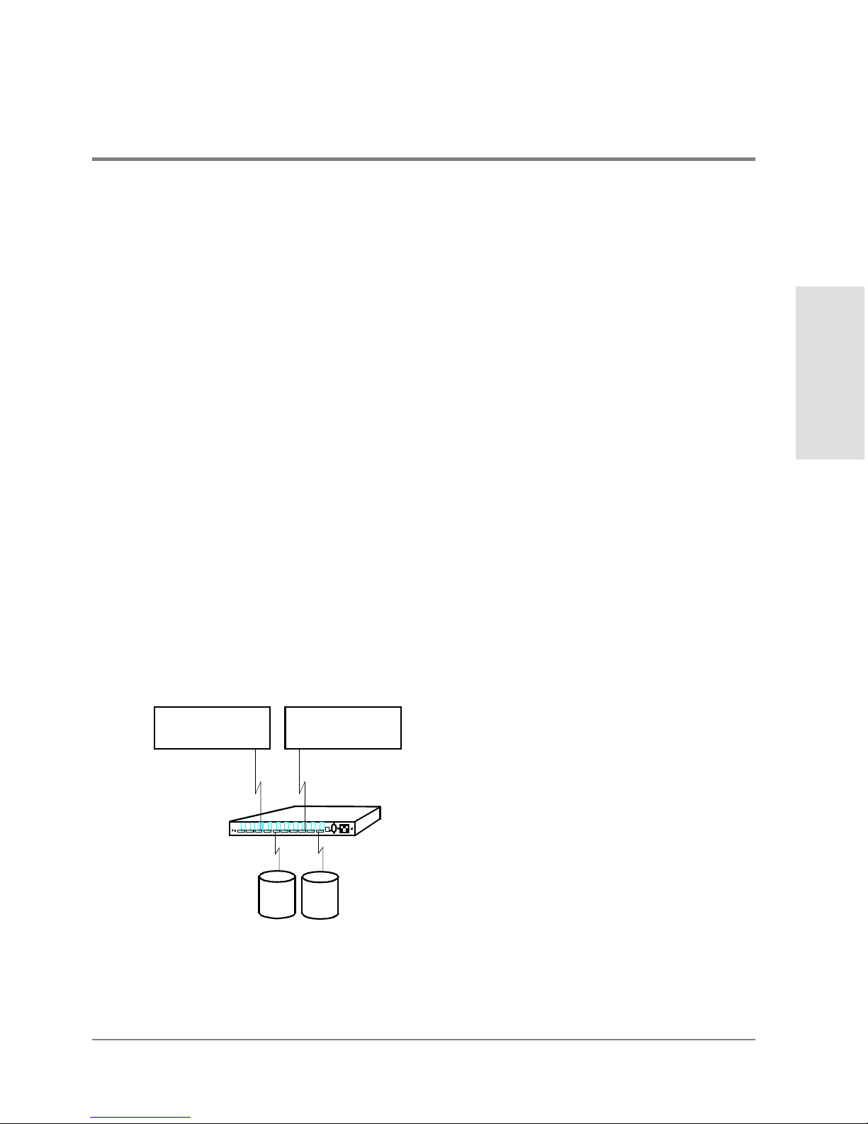
Single Short-Wave Hub Topology
For the model S10 short-wave hub, Hewlett-Packard recommends 50-micron multimode
fiber cable for new installations, but also supports 62.5-micron multimode fiber cable with
SC-style connectors in existing installations. Stated distances assume 50-micron multimode
cable.
A server with an FC-AL short-wave adapter can connect to an hub 500 meters away. Each
of the 10 ports on the short-wave hub can connect to an FC-AL device up to 500 meters
away. The maximum distance between the server and the end FC-AL device is 1000 meters
(1 km).
Figure 4 Example Topology: 10 Ports Shared among Server and FC-AL Devices
...
...
...
...
...
...
...
...
...
...
...
...
...
...
...
...
...
...
...
...
...
...
...
...
...
...
...
...
...
...
...
...
...
...
...
...
...
...
...
...
...
...
...
...
...
...
...
...
...
...
....
.....
500 m
500 m
FC-AL Devices
HP-UX Server
or HP NetServer
Total distance between server
and FC-AL device = 1000 m
HP-UX Server
or HP NetServer
NOTE: Connecting HP-UX servers
and HP NetServers to the same hub
is NOT a supported configuration.
model S10 hub
Page 20
18 Supported Topologies
Cascaded Short-Wave Hub Topology
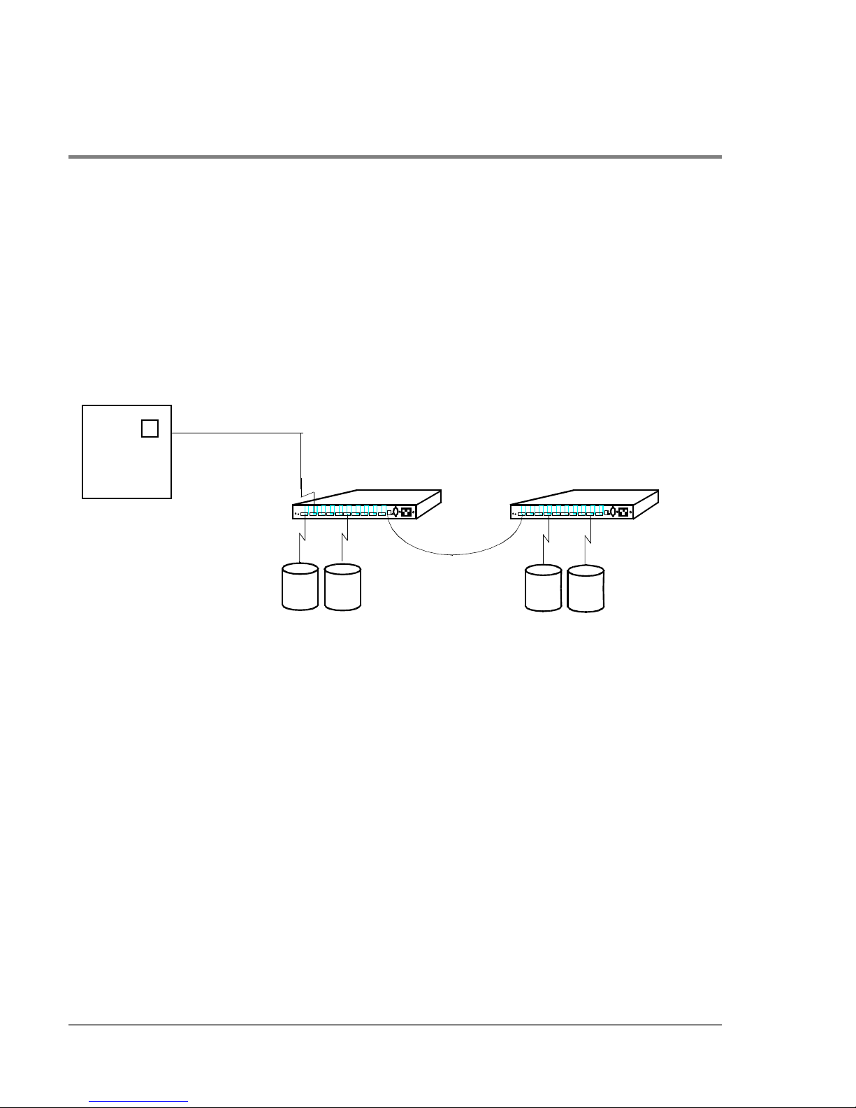
The example in Figure5 shows two model S10 hubs connected in a cascade topology.
Cascaded short-wave hubs use one port on each hub for the hub-to-hub connection. Such a
configuration increases the potential distance between nodes in the loop an additional 500
meters. The maximum distance between the server and FC-AL devices with cascaded
short-wave hubs is 1500 meters (1.5 km).
Figure 5 Example Topology: Cascaded Short-Wave Hubs
Cascaded hubs must have the same firmware versions to operate properly. If you are using
Fibre Channel Manager to manage cascaded hubs, configure the hub that has the LAN
(ethernet) connection as a parent hub and the remaining hub as a child hub (see
Configuring Cascaded Hubs on page60).
...
...
...
...
...
...
...
...
...
...
...
...
...
...
...
...
...
...
...
...
...
...
...
...
...
...
...
...
...
...
...
...
...
...
...
...
...
...
...
...
...
...
...
...
...
...
...
...
...
...
....
.....
...
...
...
...
...
...
...
...
...
...
...
...
...
...
...
...
...
...
...
...
...
...
...
...
...
...
...
...
...
...
...
...
...
...
...
...
...
...
...
...
...
...
...
...
...
...
...
...
...
...
....
.....
Maximum distance between
FC-AL Devices
HP-UX Server
500 m
500 m
500 m
FC-AL Devices
server and FC-AL device = 1500 m
or
HP NetServer
NOTE: Connecting HP-UX
servers and HP NetServers
to the same hub is NOT
a supported configuration.
model S10 hub model S10 hub
Page 21
Supported Topologies 19
Product Description
Cascaded Long-Wave Hub Topology
Cascaded FC-AL, non-OFC, model L10 long-wave hubs use the long-wave port for the hubto-hub connection. The maximum supported distance between cascaded long-wave hubs
with single-mode 9 micron cable is 3 km. The maximum distance between a server and FCAL devices on cascaded long-wave hubs is, therefore, 4000 meters (500m + 3000m +
500m). Under certain conditions, cascaded long-wave hubs are supported up to 10,000
meters (10km) (see page105 for more information). The 10-km capability only applies to
long-wave hubs connected to HP-UX servers.
Caution When cascading long-wave hubs, only connect long-wave ports to long-wave
ports or short-wave ports to short-wave ports.
Ports 1 through 9 on each long-wave hub are for connections to FC-AL devices. Ports 1
through 9 can also be used in a cascaded configuration; however, the maximum distance
between hubs decreases from 3000 meters to 500 meters.
Figure 6 Example Topology: Cascaded Long-Wave Hubs
...
...
...
...
...
...
...
...
...
...
...
...
...
...
...
...
...
...
...
...
...
...
...
...
...
...
...
...
...
...
...
...
...
...
...
...
...
...
...
...
...
...
...
...
...
...
...
...
...
...
....
.....
...
...
...
...
...
...
...
...
...
...
...
...
...
...
...
...
...
...
...
...
...
...
...
...
...
...
...
...
...
...
...
...
...
...
...
...
...
...
...
...
...
...
...
...
...
...
...
...
...
...
....
.....
3000 m (long-wave port to long-wave port only)
500 m
500 m
FC-AL Devices
FC-AL Devices
Maximum distance between
server and FC-AL device = 4000 m
NOTE: Under certain conditions, the
maximum distance between an HP-UX
server and FC-AL device can be 11,000 m.
HP-UX Server
or
HP NetServer
NOTE: Connecting HP-UX
servers and HP NetServers
to the same hub is NOT
a supported configuration.
model L10 hub
model L10 hub
Page 22

20 Supported Topologies
Cascaded hubs must have the same firmware versions to operate properly. If you are using
Fibre Channel Manager to manage cascaded hubs, configure the hub that has the LAN
(ethernet) connection as a parent hub and the remaining hub as a child hub (see page60
for more information).
Page 23

Installation
21
2 INSTALLATION
Overview
Procedure 1: Prepare to Install the Hub
Procedure 2: Unpack the Hub
Procedure 3: Verify Hub Operation
Procedure 4: Mount the Hub into a Rack (Optional)
Procedure 5: Plan the FC-AL Connections
Procedure 6: Connect FC-AL Devices
Procedure 7: Verify the Connections
Page 24

22 Overview
Overview
The procedures for installing an HP SureStore E model S10 or model L10 hub are the
following:
1. Prepare to install the hub.
2. Unpack the hub.
3. Verify hub operation.
4. Mount the hub in a rack (optional).
5. Plan the FC-AL connections.
6. Connect the FC-AL devices.
7. Verify the connections.
Read this chapter completely before installing the hub or attaching any FC-AL devices to
the hub.
Page 25

Procedure 1: Prepare to Install the Hub 23
Installation
Procedure 1: Prepare to Install the Hub
Before installing the hub:
• Complete site-required arrangements for the hub.
• Make sure electrical power and temperature control requirements are met.
• Define a strategy for integrating the hub into an existing loop.
• Draw a map of all nodes to be connected to the hub.
Page 26
24 Procedure 2: Unpack the Hub
Procedure 2: Unpack the Hub
1. Unpack and inspect the hub for damage that may have occurred during shipment.
2. Save the boxes and packing materials in case there is damage or anything needs to be
reshipped at a future date.
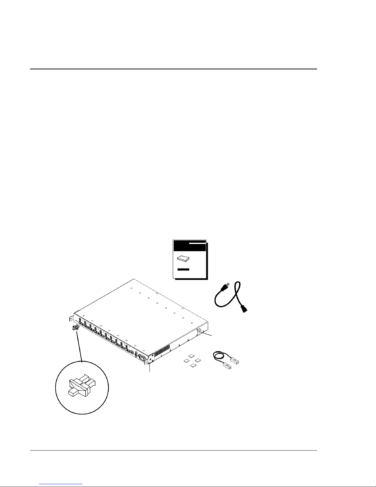
3. Verify that all items shown in Figure7 are present. Contact an HP sales representative
if items are missing.
4. If the hub is to be used as a standalone unit, attach the four rubber feet to the bottom
corners of the hub. Optionally, remove the hub’s preinstalled mounting ear brackets and
nylon retainers. The brackets and retainers are used to mount the hub in a rack.
Figure 7 Standalone Product Contents
Models S10 and L10
Service and User Manual
power cord
loopback
cable
rubber feet
mounting
nylon retainer
installed FC
port covers
ear bracket
NOTE: The long-wave hub
includes an additional loopback
cable for the long-wave port.
HP SureStore E Hub
hub
Page 27

Procedure 3: Verify Hub Operation 25
Installation
Procedure 3: Verify Hub Operation
By performing this procedure, you test the hub and verify that it operates properly before
you mount it in a rack or connect any devices to it.
1. To initialize the self-test, first plug the power cord into the hub and then into a power
receptacle. The hub does not have a power switch.
The hub runs the self-test each time the power cord is plugged in or the Reset button is
pressed.
Note The hub’s power supply automatically adjusts to a range of 100 VAC ±10% or
240VAC ±10%.
2. The hub finishes the self-test in less than 15 seconds.
If the Fault LED (amber) stays on after self-test, the hub failed. Refer to chapter 4,
Troubleshooting, or contact an HP service representative for assistance.
If the Power LED does not light, refer to chapter4, Troubleshooting, or contact an HP
service representative.
Note Interruptions to the hub’s AC power source initiate a self-test. Make sure the
power source circuits are properly grounded before using the supplied power
cord to connect the hub to the circuit.
3. Verify that each Fibre Channel port is operating properly. Insert the loopback cable into
the port and verify that the port status LED turns on. Both ends of the loopback cable
plug into the port connectors.
If you plan to use Fibre Channel Manager to manage the hub, continue with step4. If you
do not plan to use Fibre Channel Manager or another hub management tool, go to step7.
Page 28

26 Procedure 3: Verify Hub Operation
4. Verify that the 10Base-T port is operating properly. Insert an ethernet cable that is
connected to the LAN into the 10Base-T port, and verify that the 10Base-T status LED
turns on. (The status LED may begin flashing.)
5. Set the hub IP address and configure the hub as described in chapter 3, RS-232 Interface
Functions.
6. Verify the connection between the HP-UX server and the hub. At the management server
where Fibre Channel Manager is or will be installed, execute the following command:
/etc/ping <hub IP address> Example: /etc/ping 15.43.214.13
Fibre Channel Manager requires HP-UX 10.20 or 11.0 on the management server.
If you are unable to ping the hub, refer to If the Management Server Cannot Ping the
Hub on page78.
7. Unplug the hub.
Page 29
Procedure 4: Mount the Hub into a Rack (Optional) 27
Installation
Procedure 4: Mount the Hub into a Rack (Optional)
The hub mounts into any standard HP 19-inch wide EIA cabinet. The hub’s front panel will
face the rear of the cabinet. The front of the hub contains the 10 Fibre Channel connectors.
You will need a T25 Torx head screwdriver to complete this procedure.
1. Record the serial number, located on the bottom of the hub, and the MAC address,
located under the 10Base-T port. The MAC address is unique and cannot be changed.
2. Verify that the rack is adequately secured and has enough space (1 EIA) for the hub.
Remove filler panels as needed from the front of the cabinet and open the rear door.
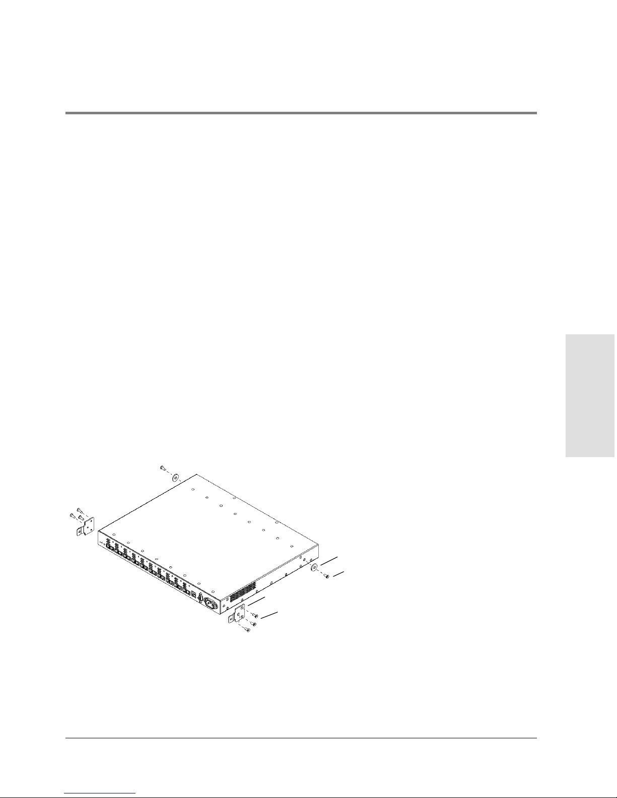
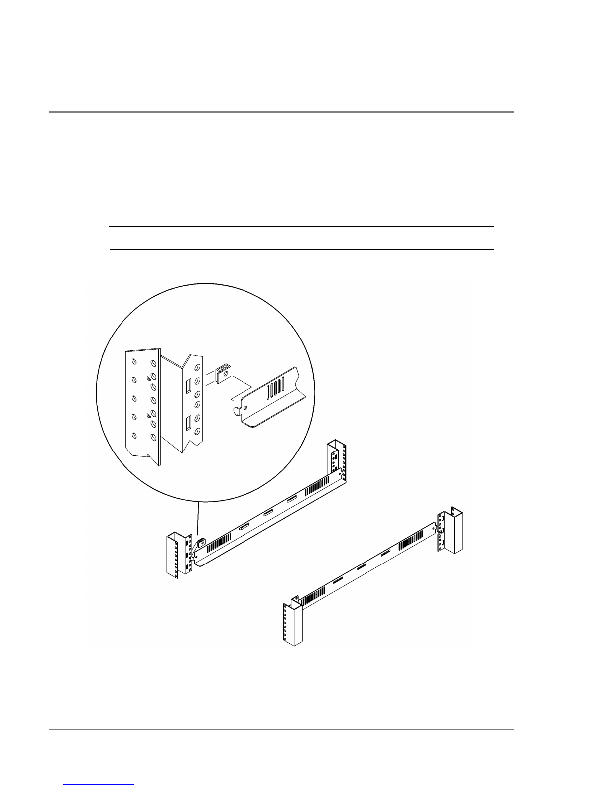
3. If the rubber feet are attached to the bottom of the hub, peel off the feet. Attach the
mounting ear brackets and nylon retainers if they are missing from the left and right
sides of the hub (Figure8).
Secure the mounting ear brackets with three M3 x .5 screws to each front outside
corner, turning the angled end of the bracket outward. Attach the nylon retainers with
one screw through the center of the retainer and into the hole in each side of the hub.
Figure 8 Replacing Mounting Ear Brackets and Nylon Retainers
4. Slide a sheet metal nut onto the outer column in the back of the rack. Make sure to align
the hole in the nut with the hole at the selected EIA location on the column.
3 M3x.5 machine screws
mounting ear bracket
1 M3x.5 machine screw
nylon retainer
Page 30
28 Procedure 4: Mount the Hub into a Rack (Optional)
5. Insert one end of the left rail in the adjoining slot. Line up the hole in the rail lines with
the holes in the nut and column (Figure9).
6. Use a second sheet metal nut and repeat steps 4 and 5 to attach the other end of the rail
to the inner column on the front of the rack.
Note DO NOT attach screws at this time.
Figure 9 Installing Rails
front of rack
rear of rack
Page 31
Procedure 4: Mount the Hub into a Rack (Optional) 29
Installation
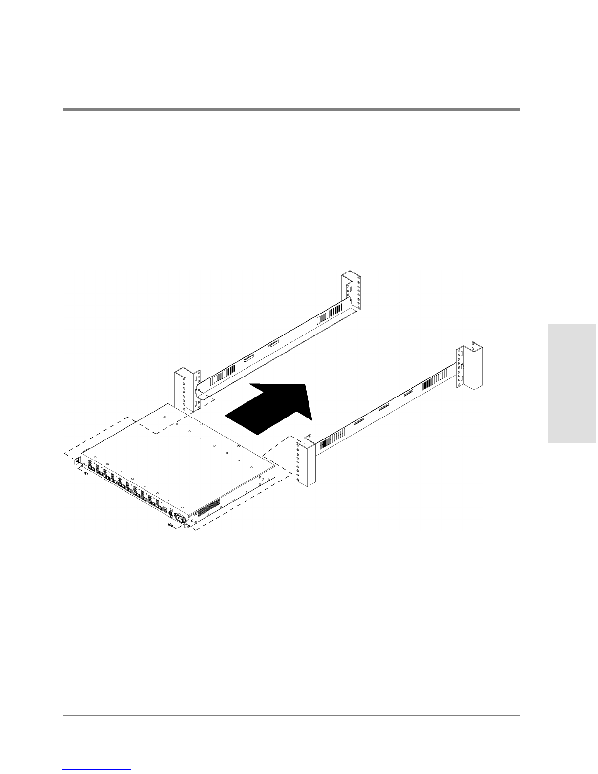
7. Repeat step4 through step6 to install the right rail.
8. Position the hub in the rack. Align the hole in each mounting ear bracket with the holes
in the assembled rail, nut, and column.
9. Insert a 10–32 x .625 machine screw through the mounting ear bracket, rail, nut, and
column on each side of the hub (Figure10). Tighten the screws.
Figure 10 Installing the Hub into the Rack
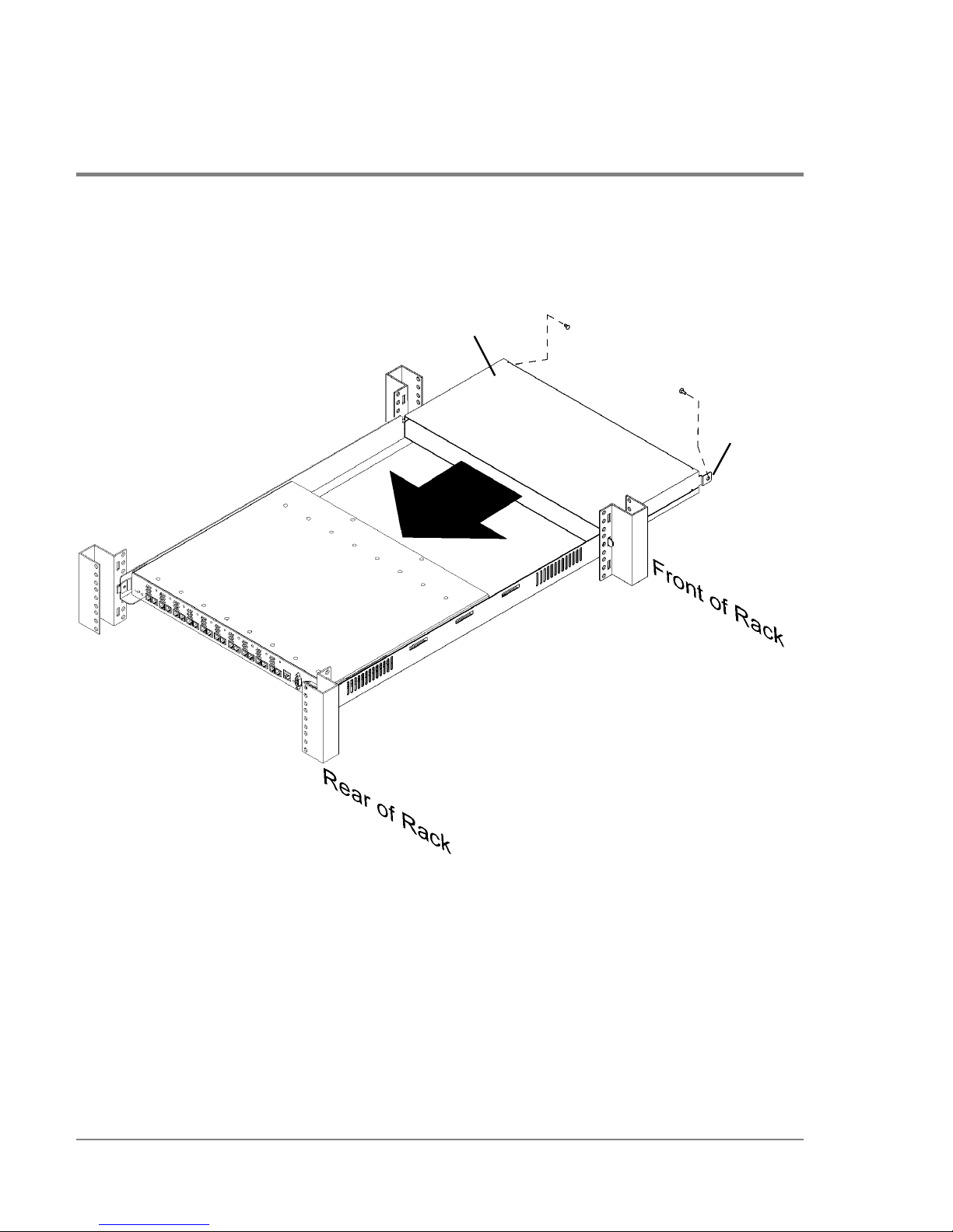
10. Slide the plenum shroud into the front side of the rack. Align the holes in the plenum
shroud brackets with the holes in the assembled rails and outer posts.
Page 32
30 Procedure 4: Mount the Hub into a Rack (Optional)
11. Secure the brackets to the posts with 10–32 x .625 machine screws (Figure11).
Figure 11 Installing the Plenum Shroud
plenum shroud
bracket
Page 33
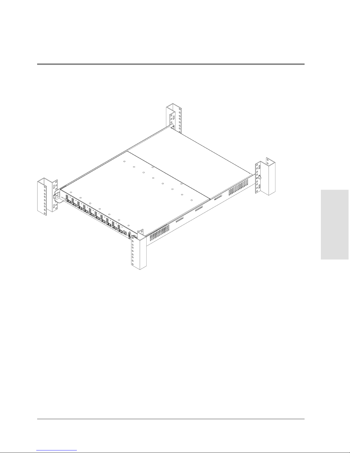
Procedure 4: Mount the Hub into a Rack (Optional) 31
Installation
Figure 12 Hub Correctly Installed in a Rack
12. Plug the PDU cable into the cabinet PDU when you are ready to power on the hub. The
hub finishes the self-test in less than 15 seconds. Verify that the hub passes the self-test.
If the Fault LED (amber) stays on after self-test, the hub failed. Refer to chapter4,
Troubleshooting, or contact an HP service representative for assistance.
If the Power LED is not lighted, refer to chapter4, Troubleshooting, or contact an HP
service representative.
13. Reinstall filler panels over the plenum shroud.
Page 34

32 Procedure 5: Plan the FC-AL Connections
Procedure 5: Plan the FC-AL Connections
The hub does not require drivers or specific versions of operating systems. However,
systems and FC-AL devices that can connect to the hub do have driver and operating
system requirements. Contact an HP sales representative for information on hardware and
software requirements for the systems or FC-AL devices you plan to connect to the hub.
The HP Fibre Channel Manager User Manual lists operating system requirements for
Fibre Channel Manager.
1. Verify that the loop cabling configuration is correct by comparing it to the cabling
examples on the following pages. Modify the network cabling map as needed.
Caution Incorrect wiring can lead to problems such as devices left off the loop and
inaccessible by the server. Follow the guidelines below before starting.
2. Refer to your cabling map to review the user-assigned loop ID (hardware address) of
each FC-AL device to be connected to the hub, and verify that each ID is unique.
Duplicate IDs on the loop can cause problems.
3. Verify that the connections between the hub port and the FC-AL mass storage device or
the FC-AL adapter are of the same wave type and speed. For example, plan to connect
a short-wave port on the hub to a short-wave port on an FC-AL device.
4. Document the planned connections in a cabling map.
Correct Cabling Example for a Short-Wave Hub
For the model S10 short-wave hub, Hewlett-Packard recommends 50-micron multimode
fiber cable for new installations but also supports 62.5-micron multimode fiber cable with
SC-style connectors in existing installations.
Page 35

Procedure 5: Plan the FC-AL Connections 33
Installation
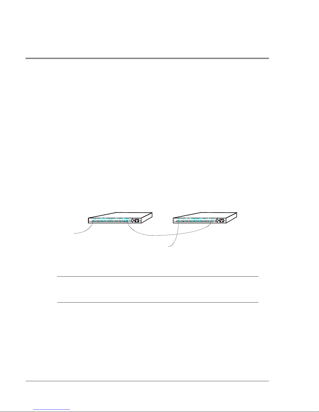
In a cascaded configuration of model S10 short-wave hubs, connect any port on the first
hub to any port on the second hub. Figure13 includes all 18 nodes in the loop formed by
FC-AL Device 1, Hub A, Hub B, and FC-AL Device 2:
– Port 1 on Hub A connects to FC-AL Device 1.
– Port 10 of Hub A connects to Port 1 of Hub B.
– Port 10 on Hub B connects to FC-AL Device 2.
In this configuration, any unused port on Hub A or Hub B can connect to any compatible
FC-AL device. This is just one example of cascaded short-wave hubs. The connection
between short-wave hubs can occupy any combination of ports.
Figure 13 Cascaded Short-Wave Hub Configuration
Note If you plan to use Fibre Channel Manager to manage cascaded hubs, you must
configure the hub that has the LAN (ethernet) connection as a parent hub and
the remaining hub as a child hub (see Configuring Cascaded Hubs on page60).
Correct Cabling Example for a Long-Wave Hub
Hewlett-Packard recommends 9-micron, single-mode fiber cable for the long-wave port.
For ports 1 through 9, the short-wave ports, Hewlett-Packard recommends 50-micron
multimode fiber cable for new installations but also supports 62.5-micron multimode fiber
cable with SC-style connectors in existing installations.
...
...
...
...
...
...
...
...
...
...
...
...
...
...
...
...
...
...
...
...
...
...
...
...
...
...
...
...
...
...
...
...
...
...
...
...
...
...
...
...
...
...
...
...
...
...
...
...
...
...
....
.....
...
...
...
...
...
...
...
...
...
...
...
...
...
...
...
...
...
...
...
...
...
...
...
...
...
...
...
...
...
...
...
...
...
...
...
...
...
...
...
...
...
...
...
...
...
...
...
...
...
...
....
.....
FC-AL Device 2
Short-Wave Hub A Short-Wave Hub B
FC-AL Device 1
Page 36
34 Procedure 5: Plan the FC-AL Connections
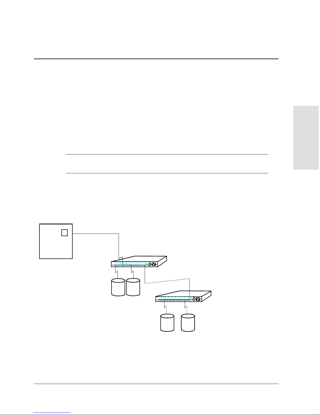
In a cascaded configuration of FC-AL long-wave hubs, connect the long-wave port on the
first hub to the long-wave port on the second hub. Figure14 shows all 18 nodes in the loop
formed by FC-AL Device 1, Hub A, Hub B, and FC-AL Device 2:
– Port 1 on Hub A connects to FC-AL Device 1.
– The long-wave port of Hub A connects to the long-wave port of Hub B.
– Port 1 on Hub B connects to FC-AL Device 2.
Long-wave hubs can be cascaded with ports 1 through 9 (the short-wave ports), but the
supported distance between hubs is reduced from 3000 meters to 500 meters. When
cascading long-wave hubs, ONLY connect long-wave ports to long-wave ports or shortwave ports to short-wave ports. Any unused short-wave port on Hub A or Hub B can
connect to any compatible FC-AL device.
Figure 14 Cascaded Long-Wave Hub Configuration
Note If you plan to use Fibre Channel Manager to manage cascaded hubs, you must
configure the hub that has the LAN (ethernet) connection as a parent hub and
the remaining hub as a child hub (see Configuring Cascaded Hubs on page60).
...
...
...
...
...
...
...
...
...
...
...
...
...
...
...
...
...
...
...
...
...
...
...
...
...
...
...
...
...
...
...
...
...
...
...
...
...
...
...
...
...
...
...
...
...
...
...
...
...
...
....
.....
...
...
...
...
...
...
...
...
...
...
...
...
...
...
...
...
...
...
...
...
...
...
...
...
...
...
...
...
...
...
...
...
...
...
...
...
...
...
...
...
...
...
...
...
...
...
...
...
...
...
....
.....
FC-AL Device 1
FC-AL Device 2
Long-Wave Hub A Long-Wave Hub B
Page 37
Procedure 5: Plan the FC-AL Connections 35
Installation
Incorrect Cabling Examples
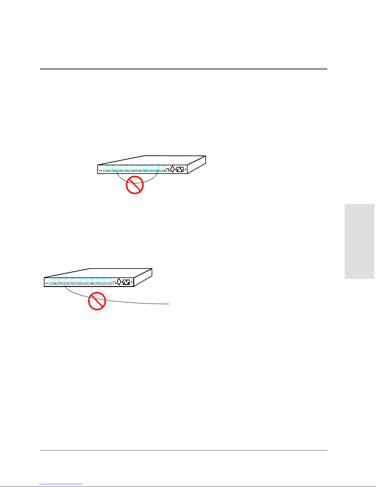
DO NOT cable together two ports on the same hub. Ports between the two connections
will be eliminated from the loop.
Figure 15 Incorrect Cabling Example: Connected Ports on the Same Hub
DO NOT leave cables that are connected to the hub disconnected at the opposite end of
the cable.
Figure 16 Incorrect Cabling Example: Disconnected Cable
...
...
...
...
...
...
...
...
...
...
...
...
...
...
...
...
...
...
...
...
...
...
...
...
...
...
...
...
...
...
...
...
...
...
...
...
...
...
...
...
...
...
...
...
...
...
...
...
...
...
....
.....
...
...
...
...
...
...
...
...
...
...
...
...
...
...
...
...
...
...
...
...
...
...
...
...
...
...
...
...
...
...
...
...
...
...
...
...
...
...
...
...
...
...
...
...
...
...
...
...
...
...
....
.....
Not connected
Page 38

36 Procedure 5: Plan the FC-AL Connections
DO NOT attach more than one cable between any two hubs.
Figure 17 Incorrect Cabling Example: More Than One Cable Connection Between Hubs
When cascading long-wave hubs, DO NOT connect the long-wave port to the short-wave
port on another hub. DO NOT connect long-wave FC-AL devices to long-wave hubs.
Figure 18 Incorrect Cabling Example: Long-Wave Port Connections to Wrong Device/Port
In the example in Figure18:
– The long-wave port on Hub A is incorrectly connected to Port 1, a short-wave port,
on Hub B.
– A device other than the long-wave port of another hub is attached to the long-wave
port of Hub B.
The long-wave port of Hub A should be connected to the long-wave port of Hub B.
...
...
...
...
...
...
...
...
...
...
...
...
...
...
...
...
...
...
...
...
...
...
...
...
...
...
...
...
...
...
...
...
...
...
...
...
...
...
...
...
...
...
...
...
...
...
...
...
...
...
....
.....
...
...
...
...
...
...
...
...
...
...
...
...
...
...
...
...
...
...
...
...
...
...
...
...
...
...
...
...
...
...
...
...
...
...
...
...
...
...
...
...
...
...
...
...
...
...
...
...
...
...
....
.....
...
...
...
...
...
...
...
...
...
...
...
...
...
...
...
...
...
...
...
...
...
...
...
...
...
...
...
...
...
...
...
...
...
...
...
...
...
...
...
...
...
...
...
...
...
...
...
...
...
...
....
.....
...
...
...
...
...
...
...
...
...
...
...
...
...
...
...
...
...
...
...
...
...
...
...
...
...
...
...
...
...
...
...
...
...
...
...
...
...
...
...
...
...
...
...
...
...
...
...
...
...
...
....
.....
FC-AL Device 2
Long-Wave Hub A Long-Wave Hub B
FC-AL Device 1
Page 39
Procedure 5: Plan the FC-AL Connections 37
Installation
Nonsupported Cabling Example
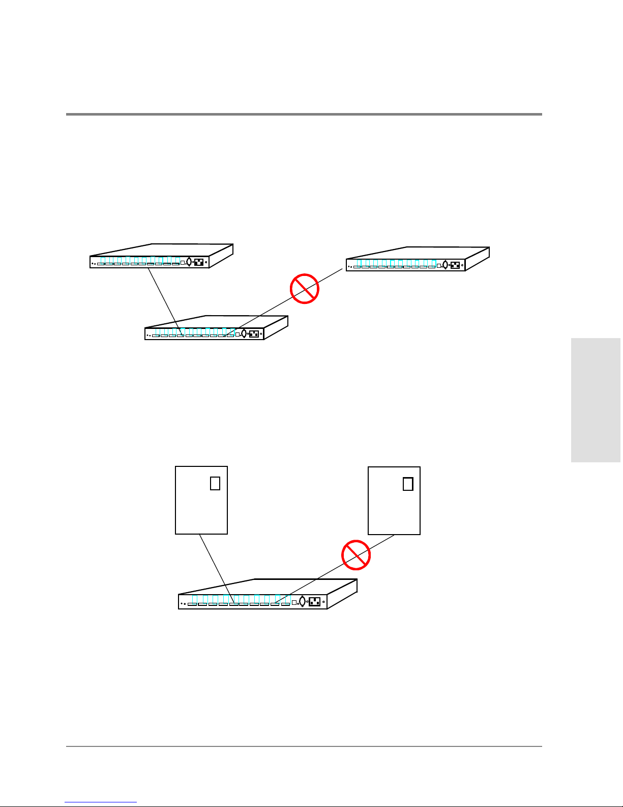
Connecting a hub to more than one other hub is NOT a supported configuration.
Figure 19 Nonsupported Cabling Example: More Than Two Hubs Connected
Connecting an HP-UX server and HP NetServer to the same hub is NOT a supported
configuration.
Figure 20 Nonsupported Cabling Example: HP-UX Server and HP NetServer
Connected to Same Hub
...
...
...
...
...
...
...
...
...
...
...
...
...
...
...
...
...
...
...
...
...
...
...
...
...
...
...
...
...
...
...
...
...
...
...
...
...
...
...
...
...
...
...
...
...
...
...
...
...
...
....
.....
...
...
...
...
...
...
...
...
...
...
...
...
...
...
...
...
...
...
...
...
...
...
...
...
...
...
...
...
...
...
...
...
...
...
...
...
...
...
...
...
...
...
...
...
...
...
...
...
...
...
....
.....
...
...
...
...
...
...
...
...
...
...
...
...
...
...
...
...
...
...
...
...
...
...
...
...
...
...
...
...
...
...
...
...
...
...
...
...
...
...
...
...
...
...
...
...
...
...
...
...
...
...
....
.....
...
...
...
...
...
...
...
...
...
...
...
...
...
...
...
...
...
...
...
...
...
...
...
...
...
...
...
...
...
...
...
...
...
...
...
...
...
...
...
...
...
...
...
...
...
...
...
...
...
...
....
.....
HP-UX
Server
HP
NetServer
Page 40

38 Procedure 6: Connect FC-AL Devices
Procedure 6: Connect FC-AL Devices
After the hub and devices are prepared, connect FC-AL devices as follows:
1. Physically set each FC-AL device to a unique loop ID (hardware address). Refer to the
FC-AL device’s manual to set the loop ID.
If devices are added during normal operation and duplicate IDs occur, the Fibre
Channel driver denies access to both devices until the address conflict is resolved.
Change the address of the second (duplicating) device.
If devices are added or device addresses changed while the system is powered off
and duplicate IDs occur, the system is unavailable until the address conflict is resolved.
An error message appears on the system console. Change the address of the second
(duplicating) device.
2. Remove the covers from the FC-AL ports. Refer to your cabling map, and begin
connecting devices to the hub. Leave the covers on ports not in use.
Caution Fiber optic cables and connectors are extremely fragile. Avoid twisting or
bending the cable beyond a 3-cm radius.
If the hub and all FC-AL devices are powered down, first plug in the hub, then
power on the devices at all the FC-AL nodes on the loop. The hub should be the first
operating component in the loop.
If the hub and all devices are powered up, you can connect the hub to a server or
FC-AL device while the server or FC-AL device is operating.
Page 41

Procedure 6: Connect FC-AL Devices 39
Installation
If the hub is to be connected to an FC-AL adapter that is connected to another FC-AL
device, follow the removal procedures in the document that came with the FC-AL
device before disconnecting the device’s cable.
If the hub is to be connected to an FC-AL device that is connected directly to a server,
follow the removal procedures in the document that came with the FC-AL device
before disconnecting the device’s cable.
When installing model L10 long-wave hubs in a cascaded topology, make sure the
long-wave port is connected only to the long-wave port on another long-wave hub.
3. For the model L10 long-wave hub, connect the long-wave loopback cable to the
long-wave port if the port is not in use.
4. Install any special files the FC-AL devices need. Refer to the device manual for details.
Page 42

40 Procedure 7: Verify the Connections
Procedure 7: Verify the Connections
After connecting devices and the server to the hub, verify the connections.
Note Because the hub is strictly a pass-through device for FC-AL traffic, there is no
hub address and the hub is not listed in ioscan output (HP-UX servers) or the
SCSI Adapters window (HP NetServers).
For HP-UX servers:
1. Use the following HP-UX command to run ioscan and check the hardware paths
between the server and the attached FC-AL devices:
ioscan -f
For details on ioscan and its options, refer to the HP-UX System Administration
Tasks Manual. Also consult the device documentation to interpret the ioscan output.
2. If the Hardware State of a device connected to the hub is “Unclaimed” or “No H/W,” see
chapter4, Troubleshooting, for more information.
For HP NetServers:
1. From the Start menu, select Settings, then select Control Panel.
2. Double-click the SCSI Adapters icon. The SCSI Adapters window appears.
3. Click the Devices tab, then verify that the FC-AL devices connected to the hub are
displayed.
Page 43

RS-232 Interface
Functions
41
3 RS-232 INTERFACE FUNCTIONS
Overview
Setting Up an RS-232 Connection
Updating the Hub Firmware
Enabling Hub Management
Running Diagnostic Tests
Viewing Hub Information
Page 44

42 Overview
Overview
This chapter describes how to use the RS-232 port to update firmware, enable hub
management, run diagnostic tests, and view hub information. The RS-232 port is located on
the front panel of the hub (see Figure1 on page14 or Figure2 on page15).
To configure the hub for Fibre Channel Manager or another management application, use
the hub’s configuration menus to set SNMP values and the IP address.
If you do not plan to manage the hub with Fibre Channel Manager or another management
application, you do not have to update the firmware or enable hub management. You do not
have to update hub firmware to run diagnostic tests or view hub information.
Before beginning the procedures in this chapter, determine the configuration values that
are required for the hub. Obtain IP addresses from the network administrator for the LAN
to which the parent hub is connected. IP addresses are optional for the child hub. Values
can be written in the spaces of the following worksheet.
Table 1 Worksheet for Hub Configuration
Parameter Parent Hub Child Hub (if any)
Firmware version (hub controller) Same as parent
Firmware version (device agent) Same as parent
Proxy master option ENABLED DISABLED
Port bypass persistence option DISABLED DISABLED
Hub IP address
Subnet mask
Default gateway address
Trap IP address (optional, max. of 4)
Trap IP address (optional, max. of 4)
Trap IP address (optional, max. of 4)
Trap IP address (optional, max. of 4)
Page 45

Overview 43
RS-232 Interface
Functions
About the RS-232 Main Menu
When you set up an RS-232 connection and boot the hub, the hub management Main menu
appears on the terminal screen.
Fibre Channel Hub Model Number: HP3724A
Device Agent Version: 02.14
Hub Controller Version: 03.06
Agent Boot PROM Version: 01.04
Status of Device Agent self-test: passed
Status of Hub Controller self-test: passed
1. Reset hub and run self-test
2. Set Networking parameters
3. Management options
4. Hub information
The model and version numbers displayed can be different from the examples shown in
this manual. Fewer menu options are displayed in earlier versions of the hub firmware. To
update the firmware, follow the instructions given in Updating the Hub Firmware on
page48.
If the Main menu does not appear and the display shows the following message, press the
Reset button on the front panel of the hub.
pROBE+>
The Main menu provides four options:
1. Reset hub and run self-test
This option resets the hub and runs the diagnostic tests. When changes are made to
the hub, they do not take effect until the hub is reset.
SNMP get community name
SNMP set community name
SNMP trap community name
Table 1 Worksheet for Hub Configuration (cont’d)
Parameter Parent Hub Child Hub (if any)
Page 46

44 Overview
2. Set Networking parameters
Use this option to view or change the hub network configuration, including the IP
address. For cascaded hubs, use this option to define parent/child relationships.
3. Management options
This option displays a menu for changing SNMP values.
4. Hub information
Use this option to view the media access control (MAC) address and serial number.
Tips for Using the RS-232 Interface
• To enter a command, type the number that corresponds to the desired option, then press
<ENTER>. An appropriate submenu appears.
• To enter a value, type the value and then press <ENTER>. To enter multiple values, enter
each one separately.
• Enter 1 to return to the previous menu or option.
• From the Main menu, enter 1 to reset the hub. New self-test values are displayed after
the hub has been reset.
• When you have finished making changes, you can close the terminal connection and
disconnect the serial cable.
Page 47

Setting Up an RS-232 Connection 45
RS-232 Interface
Functions
Setting Up an RS-232 Connection
The RS-232 interface requires a connection from the hub to a dumb terminal or to a PC with
a terminal emulator program. A PC is required for updating firmware. To access the hub
configuration menus, you can use either a PC or a dumb terminal.
Setting Up a Connection to a PC
Setting up a PC connection requires the following equipment:
• FC-AL hub
• A personal computer, such as an OmniBook notebook PC
• A null-modem serial cable
The cable must have a DB-9 female connector for connection to the hub. For example,
for an OmniBook notebook PC, you can use an HP 24542U RS-232 cable, which has
two DB-9 female connectors.
• Terminal emulation software, such as HyperTerminal
The terminal emulator must be capable of ASCII text file transfers and support VT100
or ANSI emulation with no flow control.
To establish a connection, do the following:
1. Connect the serial cable between the RS-232 port on the hub and a serial (COM) port on
the PC.
Page 48

46 Setting Up an RS-232 Connection
2. Run the terminal emulator application. Configure the terminal emulator to use the
following settings:
3. Press <ENTER> to display the hub configuration Main menu.
If the Main menu does not appear and the following message is displayed, press the
Reset button on the front panel of the hub:
pROBE+>
Setting Up a Connection to a Dumb Terminal
Setting up a connection between a dumb terminal and the hub requires the following
equipment:
• FC-AL hub
• Any terminal that supports VT100 emulation with no flow control
The terminal must be in vt100 mode before you continue with this procedure. Refer to
the terminal’s manual for more information.
• A null-modem serial cable
The cable must have a DB-9 female connector for connection to the hub.
To establish a connection, do the following:
1. Connect the serial cable between the RS-232 ports on the hub and the terminal.
2. Power on the terminal.
Baud rate: 19,200
Data bits: 8
Parity bits: none
Stop bits: 1
Parity check: off
Flow control: none
Page 49

Setting Up an RS-232 Connection 47
RS-232 Interface
Functions
3. Configure the terminal to use the following settings:
4. Press <ENTER> to display the hub configuration Main menu.
If the Main menu does not appear and the following message is displayed, press the
Reset button on the front panel of the hub.
pROBE+>
Baud rate: 19,200
Data bits: 8
Parity bits: none
Stop bits: 1
Parity check: off
Flow control: none
Page 50

48 Updating the Hub Firmware
Updating the Hub Firmware
The hub’s management tool, Fibre Channel Manager, requires the following versions of hub
firmware: .
Before you begin this procedure, determine whether the hub requires a firmware update to
communicate with Fibre Channel Manager. A label on the bottom of the hub chassis lists
the EDC datecode. If the EDC datecode is C-38XX or higher, the hub has the required
firmware.If you are not able to access the label, determine the firmware versions by
connecting to the hub’s RS-232 interface (see Setting Up an RS-232 Connection on page45).
To update the hub firmware, use a PC connected to the hub. First copy the firmware files to
the PC and then transfer the firmware from the PC to the hub.
The general process for updating the hub firmware is the following:
1. Obtain the current firmware.
2. Reboot the hub.
3. Update the hub controller firmware.
4. Update the hub device agent code.
5. Reset the hub.
6. Set manufacturing values.
If any hubs are cascaded, repeat the procedures for each child hub. Parent and child hubs
must have identical versions of the firmware.
The procedures in this section require a total of 30 to 60 minutes to complete.
Device Agent 02.14 (or higher)
Hub Controller 03.06 (or higher)
Page 51

Updating the Hub Firmware 49
RS-232 Interface
Functions
Caution If a hub power failure occurs during the transfer of the new firmware to the hub,
the hub can become inoperable.
Procedure 1: Obtain the Current Firmware
The current release of the hub firmware is available at the Hewlett-Packard Software
Depot.
1. From a Netscape browser window, enter the URL for the Hewlett-Packard Software
Depot (http://www.software.hp.com).
2. Click the Network & Systems Administration link, then click the HP Fibre Channel
Manager link.
3. Click the Download Hub firmware link on the HP Fibre Channel Manager home page.
The firmware files are available as a self-extracting ZIP file for Windows and as a
compressed tar file for HP-UX. These compressed files include the current and
previous release version of the firmware. The previous release versions are necessary
if you need to recover from an unsuccessful firmware update.
4. Follow the instructions at the web site to download the firmware files.
5. Copy the files to the PC you will use to download the new firmware files to the hub.
Procedure 2: Reboot the Hub
1. Set up an RS-232 connection as described in Setting Up a Connection to a PC on page45.
2. After the hub configuration Main menu appears, enter 1 to reset the hub.
The screen begins to display the status of the hub. To reboot, you must interrupt the
status display to go to the Boot menu.
3. Wait for the following message:
Press Enter key for Boot Menu, Agent boot in 6 seconds
Page 52

50 Updating the Hub Firmware
4. Immediately press <ENTER> to display the Boot menu:
Boot menu V01.04
1. Download and update Device Agent code
2. Download and update Hub-Controller code
3. Reset hub and run self test
4. Start Normal Hub operation
Caution Do not update the device agent code at this time. The hub controller firmware
must be updated first.The hub will not operate properly if the firmware is
updated in the wrong sequence. See If Firmware Upgrade Appears to Fail on
page79 if the firmware is updated in the wrong sequence.
Procedure 3: Update the Hub Controller Firmware
1. From the Boot menu, enter 2 to update the hub controller firmware. A prompt appears
for you to begin file transfer; for example:
Ready to download Hub-Controller code to RAM
Start ASCII file (S-record format) transfer now
<Refer to terminal emulator user manual for instructions>
Press control-C at any time to cancel
2. From the terminal emulator application, select the transfer option to send a text file.
The hub’s firmware files have a .frm suffix. Verify that the terminal emulator application
is displaying all file types.
3. Send the following file you downloaded from the web site. (Firmware filenames change
when updated versions are released. Always check the Hewlett-Packard Software
Depot for the latest firmware version and download instructions.) The default directory
for this file is C:\Temp\HUB_FW.
IFCH3820.FRM
Several rows of dots appear to indicate download progress; for example:
...................................................................
...................................................................
....................................
Page 53

Updating the Hub Firmware 51
RS-232 Interface
Functions
After a few minutes, the transfer prompt appears; for example:
Done, memory range [$00001000:$00004FFF]
Ready to transfer Hub-Controller code from RAM to FLASH
Note, once started, this step must not be interrupted
Press Enter to start, control-C to cancel
The values displayed for memory range represent low-level diagnostics; the values
displayed in the status message can be different from the values shown here.
4. Press <ENTER>. Additional progress indicators and status messages appear; for
example:
--+
$..................................................................
*******************************************************************
************************
The hub is automatically rebooted and additional messages appear:
DRAM test (this will take about 10 seconds) > passed
SEEPROM test (this will take about 1 second) > passed
FLASH checksum (this will take about 2 seconds) > passed
Press Enter key for Boot Menu, Agent boot in 7 seconds
To reboot, you must interrupt the display to go to the Boot menu.
5. Immediately press <ENTER> to display the Boot menu.
Note If the Main menu appears instead of the messages above, enter 1 to reboot the
hub, then press <ENTER> before the timeout period is finished.
If the Main menu appears, ignore the Hub Controller version number. It may be
blank or UNKNOWN. If the version number is blank or UNKNOWN, the upgrade
version number will appear in the Main menu after you update the Hub Device
Agent code and reset the hub.
Page 54

52 Updating the Hub Firmware
Procedure 4: Update the Hub Device Agent Code
Caution The hub controller firmware must be updated before the device agent code.
The hub will not operate properly if the firmware is updated in the wrong
sequence. See If Firmware Upgrade Appears to Fail on page79 if the firmware
is updated in the wrong sequence.
1. From the Boot menu, enter 1 to update the device agent code. A prompt appears for you
to begin file transfer; for example:
Ready to download Device Agent code to RAM
Start ASCII file (S-record format) transfer now
<Refer to terminal emulator user manual for instructions>
Press control-C at any time to cancel
2. From the terminal emulator application, select the transfer option to send a text file.
The hub’s firmware files have a .frm suffix. Verify that the terminal emulator application
is displaying all file types.
3. Send the following file you downloaded from the web site. (Firmware filenames change
when updated versions are released. Always check the Hewlett-Packard Software
Depot for the latest firmware version and download instructions.) The default directory
for this file is C:\Temp\HUB_FW.
IFCH3821.FRM
The screen is filled with rows of progress indicator dots as the file is transferred; for
example:
...................................................................
...................................................................
....................................
The transfer process can take 10 to 40 minutes. When the file transfer has been
completed, status messages and a transfer prompt appear; for example:
Done, memory range [$00001000:$0005D666]
Ready to transfer Device Agent code from RAM to FLASH
Note, once started, this step must not be interrupted
Press Enter to start, control-C to cancel
Page 55

Updating the Hub Firmware 53
RS-232 Interface
Functions
The values displayed for memory range represent low-level diagnostics; the values
displayed in the status message can be different from the values shown here.
4. Press <ENTER>. The screen displays status messages; for example:
FLASH programming will take about 40 seconds
FLASH pgm:[$001000:$101000)->[$800000:$900000) >
Caution Do not interrupt the display or press any keys during this process.
After about 40 seconds, the display continues.
When FLASH programming is completed, the checksum appears; for example:
FLASH programming will take about 40 seconds
FLASH pgm:[$001000:$101000)->[$800000:$900000) > complete, no errors
New FLASH checksum = 0x7B04
The value displayed can be different from the example shown here. Then the Boot
menu appears again.
Procedure 5: Reset the Hub
After updating the hub firmware, you must reset the hub for the new firmware to take
effect.
1. From the Boot menu, enter 3 to reset the hub and run the hub self-test. The Main menu
appears and displays the new hub controller and device agent code version numbers.
2. Verify that the upgrade version numbers are displayed, then go to Procedure 6: Set
Manufacturing Values.
If the Main menu displays the Hub Controller version as Unknown, continue with step 3.
Page 56

54 Updating the Hub Firmware
3. From the Main menu, enter 2 (Set Networking parameters) to display the Network
Setup menu.
Network Setup Menu:
1. Return to Main Menu
2. Select IP address [current = nnn.nnn.nnn.nnn]
3. Select Subnetworking Mask [current = nnn.nnn.nnn.nnn]
4. Select Default Gateway address [current = nnn.nnn.nnn.nnn]
5. Save Network Setup changes and reboot
6. Proxy Master Setup
4. Enter 6 to display the Proxy Master menu:
Proxy Master Menu: <Current state: Proxy Master DISABLED>
1. Return to previous Menu
2. Toggle current Proxy Master state and reboot
5. Enter 2 to change the Proxy Master setting to ENABLED and reboot the hub. When the
Main menu appears, verify the new Hub Controller version.
Procedure 6: Set Manufacturing Values
After resetting the hub and verifying the new firmware versions, set the system.sysDescr
and system.sysObjectID values.
1. From the Main menu, enter mfg to display the Manufacturing Settings Menu.
Manufacturing Settings Menu:
1. Return to Main Menu
2. Set sysdescr [current = ]
3. Set system OID [current = 1.3.6.1.4.1]
4. Toggle port bypass persistence mode [current = Enabled]
>
2. Enter 2 to display the Set sysDescr string Menu.
Set sysDescr string Menu: [current = ]
1. Return to Manufacturing Settings Menu
or enter new sysDescr string
>
Page 57

Updating the Hub Firmware 55
RS-232 Interface
Functions
3. For the model S10 short-wave hub, enter: HP A3724A FC-AL Shortwave Hub
For the model L10 long-wave hub, enter: HP A4839A FC-AL Longwave Hub
The Set sysDescr string Menu appears with the new setting. (The following example is
for the short-wave hub.)
Set sysDescr string Menu: [current = HP A3724A FC-AL Shortwave Hub]
1. Return to Manufacturing Settings Menu
or enter new sysDescr string
>
4. Verify that the setting is correct, then enter 1 to return to the Manufacturing Settings
Menu.
Manufacturing Settings Menu:
1. Return to Main Menu
2. Set sysdescr [current = HP A3724A FC-AL Shortwave Hub]
3. Set system OID [current = 1.3.6.1.4.1]
4. Toggle port bypass persistence mode [current = Enabled]
>
5. Enter 3 to display the Set System OID Menu.
Set System OID Menu: [current = 1.3.6.1.4.1]
1. Return to Manufacturing Settings Menu
or enter new system OID suffix in dotted decimal format
The suffix entered will be appended to 1.3.6.1.4.1
example: if desired system OID is 1.3.6.1.4.1.2.3.4, then enter
2.3.4
>
6. Enter 11.2.3.7.5.10
Page 58

56 Updating the Hub Firmware
The Set System OID Menu appears with the new setting.
Set System OID Menu: [current = 1.3.6.1.4.1.11.2.3.7.5.10]
1. Return to Manufacturing Settings Menu
or enter new system OID suffix in dotted decimal format
The suffix entered will be appended to 1.3.6.1.4.1
example: if desired system OID is 1.3.6.1.4.1.2.3.4, then enter
2.3.4
>
7. Verify that the setting is correct, then enter 1 to return to the Manufacturing Settings
Menu.
Manufacturing Settings Menu:
1. Return to Main Menu
2. Set sysdescr [current = HP A3724A FC-AL Shortwave Hub]
3. Set system OID [current = 1.3.6.1.4.1.11.2.3.7.5.10]
4. Toggle port bypass persistence mode [current = Enabled]
>
If you are using Fibre Channel Manager to manage the hub, the bypass persistence setting
controls the behavior of bypassed ports when the hub is power cycled or reset.
If the hub is power-cycled or reset with bypass persistence disabled, the hub
automatically enables all ports that were previously bypassed in Fibre Channel Manager. If
the hub is reset with bypass persistence enabled , the hub continues to bypass ports that
were bypassed in Fibre Channel Manager.
8. Enter 4 to disable port bypass persistence. Verify that the port bypass persistence mode
is disabled.
Manufacturing Settings Menu:
1. Return to Main Menu
2. Set sysdescr [current = HP A3724A FC-AL Shortwave Hub]
3. Set system OID [current = 1.3.6.1.4.1.11.2.3.7.5.10]
4. Toggle port bypass persistence mode [current = Disabled]
>
9. Enter 1 to return to the Main menu.
10. Exit the terminal emulator application and disconnect the serial cable from the hub and
the PC.
Page 59

Enabling Hub Management 57
RS-232 Interface
Functions
Enabling Hub Management
Use the hub RS-232 management menus to enable the hub to be managed by Fibre Channel
Manager. To enable hub management:
• Set hub IP address and network configuration options.
• Set SNMP values.
• Configure cascaded hubs (if you plan to manage hubs in a cascaded configuration).
Setting Hub IP Address and Network Configuration Options
Use this procedure to set the following parameters on the hub.
• Hub IP address
• Subnetworking mask
• Default gateway address
If you have hubs in a cascaded configuration, only perform this procedure for the parent
hub. The parent hub should be the hub that has the LAN (ethernet) connection. Refer to the
values you entered in Table1 on page42 as you set the above parameters.
To set hub IP address and network configuration options:
1. Set up an RS-232 connection between the parent hub and a PC or dumb terminal (see
Setting Up a Connection to a PC on page45 or Setting Up a Connection to a Dumb
Terminal on page46).
Page 60

58 Enabling Hub Management
2. From the Main menu, enter 2 (Set Networking parameters) to display the Network
Setup menu:
Network Setup Menu:
1. Return to Main Menu
2. Select IP address [current = nnn.nnn.nnn.nnn]
3. Select Subnetworking Mask [current = nnn.nnn.nnn.nnn]
4. Select Default Gateway address [current = nnn.nnn.nnn.nnn]
5. Save Network Setup changes and reboot
6. Proxy Master Setup
3. Enter 2 to set the hub IP address. A command prompt appears.
4. Type the IP address for the hub, then press <ENTER>.
5. Enter 3 to set the Subnetworking Mask. A command prompt appears.
6. Type the Subnetworking Mask for the hub, then press <ENTER>.
7. Enter 4 to set the Default Gateway address. A command prompt appears.
8. Type the Default Gateway address for the hub, then press <ENTER>.
9. Enter 5 to save your changes. The hub is rebooted with the new values. The Main menu
appears.
Caution You must enter 5 to save changes. If you do not want to change the hub values,
do not enter 5. Instead, enter 1 to return to the Main menu.
Verifying and Setting SNMP Values
Use the following procedure to set the following SNMP values. If you have hubs in a
cascaded configuration, only perform this procedure for the parent hub. The parent hub
should be the hub that has the LAN (ethernet) connection. Refer to the values you entered
in Table1 on page42 as you set the above parameters.
• get community name
Page 61

Enabling Hub Management 59
RS-232 Interface
Functions
The get community name must be the same name used when a device was added to
Fibre Channel Manager. If the names are not identical, Fibre Channel Manager cannot
report management information for this hub. The default value is public.
• set community name
The set community name must be the same name used when a device was added to
Fibre Channel Manager. If the names are not identical, Fibre Channel Manager cannot
set management parameters for this hub. The default value is private.
• SNMP trap community name
The hub includes the trap community name in event messages sent to the management
application. The default value is SNMP_trap.
• trap server IP addresses
This option sets the destination addresses for SNMP event messages. A maximum of
four addresses can be specified.
Caution If you enter the name of an existing IP address, the existing address is deleted.
• MIB-2 system name
This value is returned for the SNMP MIB-2 system.sysName variable.
• default values
This option resets the get, set, and trap community names to the default values.
To verify and set SNMP values, do the following:
1. Verify with your network administrator that the default get community name is
acceptable. The default is public.
2. Verify with your network administrator that the default set community name is
acceptable. The default is private.
3. Verify with your network administrator that the default trap community name is
acceptable. The default is SNMP_trap.
Page 62

60 Enabling Hub Management
4. From the Main menu, enter 3 (Management options) to display the Management
Options menu:
Management options Menu:
1. Return to Main Menu
2. Set SNMP get community name
3. Set SNMP set community name
4. Set SNMP trap community name
5. Set SNMP trap server IP addresses
6. Set MIB-2 sysname
7. Restore default values to SNMP get, set, trap community names
8. Clear SNMP trap server IP address list
5. Enter 5 to set the IP address(es) where you want Fibre Channel Manager to send traps
(optional). The Set Trap IP address Menu appears.
6. Type the trap server IP address, then press <ENTER>.
To enter additional addresses, repeat step 6. You can enter up to four IP addresses.
To delete an existing trap server IP address, enter the value of the existing IP address.
7. Enter 1 to return to the Management Options menu.
8. Enter 6 to set the MIB-2 sysname (optional). The SNMP MIB-2 sysName Menu appears.
9. Type a unique name for the hub, then press <ENTER>.
10. Enter 1 to return to the Management Options menu, then enter 1 again to return to the
Main menu.
Configuring Cascaded Hubs
By default, HP SureStore E hubs are configured as parent hubs. However, you can connect
two hubs in a cascaded configuration in which one hub (the parent) is connected to the
LAN (ethernet) and the other hub (the child) is connected to the parent hub. For
information about setting up a cascaded hub configuration, see page18 and page32.
Page 63

Enabling Hub Management 61
RS-232 Interface
Functions
Configuring the Parent Hub
If you plan to manage cascaded hubs with Fibre Channel Manager, configure the hub
connected to the LAN as a parent hub.
1. From the Main menu, enter 2 (Set Networking parameters) to display the Network
Setup menu.
Network Setup Menu:
1. Return to Main Menu
2. Select IP address [current = nnn.nnn.nnn.nnn]
3. Select Subnetworking Mask [current = nnn.nnn.nnn.nnn]
4. Select Default Gateway address [current = nnn.nnn.nnn.nnn]
5. Save Network Setup changes and reboot
6. Proxy Master Setup
2. Enter 6 to display the Proxy Master menu:
Proxy Master Menu: <Current state: Proxy Master ENABLED>
1. Return to previous Menu
2. Toggle current Proxy Master state and reboot
For the parent hub, verify that the master is ENABLED , then enter 1 to return to the
Network Setup menu. Enter 1 again to return to the Main menu.
3. Enter 5 to save your changes. The hub is rebooted with the new values.
4. Close the terminal connection and disconnect the serial cable.
Configuring the Child Hub
If you plan to manage cascaded hubs with Fibre Channel Manager, configure the hub that is
connected to the parent hub as a child hub.
1. Set up an RS-232 connection between the child hub and a PC or dumb terminal (see
Setting Up a Connection to a PC on page45 or Setting Up a Connection to a Dumb
Terminal on page46).
Page 64

62 Enabling Hub Management
2. From the Main menu, enter 3 (Management options) to display Management Options
menu:
Management options Menu:
1. Return to Main Menu
2. Set SNMP get community name
3. Set SNMP set community name
4. Set SNMP trap community name
5. Set SNMP trap server IP addresses
6. Set MIB-2 sysname
7. Restore default values to SNMP get, set, trap community names
8. Clear SNMP trap server IP address list
3. Enter 6 to set the MIB-2 sysname for the child hub (optional).
4. Type a unique name for the child hub, then press <ENTER>.
5. Enter 1 to return to the Management Options menu, then enter 1 again to return to the
Main menu.
6. From the Main menu, enter 2 (Set Networking parameters) to display the Network
Setup menu.
Network Setup Menu:
1. Return to Main Menu
2. Select IP address [current = nnn.nnn.nnn.nnn]
3. Select Subnetworking Mask [current = nnn.nnn.nnn.nnn]
4. Select Default Gateway address [current = nnn.nnn.nnn.nnn]
5. Save Network Setup changes and reboot
6. Proxy Master Setup
7. From the Network Setup menu, enter 6 to display the Proxy Master menu:
Proxy Master Menu: <Current state: Proxy Master ENABLED>
1. Return to previous Menu
2. Toggle current Proxy Master state and reboot
8. To disable the proxy master option (configure the hub as a child), enter 2. The hub is
rebooted automatically and the Main menu reappears.
To verify that the hub is configured as a child, return to the Proxy Master menu. The
proxy master state for a child hub is displayed as “DISABLED.”
Page 65

Enabling Hub Management 63
RS-232 Interface
Functions
9. Close the terminal connection and disconnect the serial cable from the child hub.
Connecting the Hubs
Connect the parent hub to the child hub. See page32 to connect short-wave hubs and
page33 to connect long-wave hubs. See page17 for information on supported cascaded
topologies.
Page 66

64 Running Diagnostic Tests
Running Diagnostic Tests
When a problem occurs in the hub, the amber Fault LED comes on. A fault can occur for
many reasons, including:
• Elevated internal temperature
• Power supply failure
• Fan malfunction
To determine the cause of the problem, run the hub self-test from the Main menu.
1. Set up an RS-232 connection between the hub and a PC or dumb terminal (see Setting
Up a Connection to a PC on page45 or Setting Up a Connection to a Dumb Terminal on
page46).
2. From the Main menu, enter 1 to reset the hub and run the self-test. If the hub fails the
self-test, an error number is displayed; for example:
Status of Hub Controller self-test: 0200
A value of 0200 in the self-test represents a fan failure. Replace the fan module as
described in Replacing the Fan Module on page88.
Any other numeric value represents an internal hub failure. Internal parts are not
replaceable. If an internal malfunction occurs, replace the hub.
WARNING Do not attempt to open the hub chassis. Uninsulated parts inside the
chassis constitute a hazard.
3. After correcting any problems, enter 1 to reset the hub.
For normal hub operation, the Hub Controller self-test status is displayed as “passed.” For
a child hub, the Hub Controller self-test status is displayed as “Unknown.”
Page 67

Viewing Hub Information 65
RS-232 Interface
Functions
Viewing Hub Information
Use the Hub Information menu to view the following hub identification information:
• MAC address
• Child device
• Serial number
To view hub information:
1. From the Main menu, enter 4 (Hub Information) to display the MAC address. The MAC
address and the Hub Information menu appear; for example:
MAC address: 0060b0-5e0827
1. Return to previous Menu
2. Display list of proxied devices
The MAC address is unique for each hub and cannot be changed.
2. To display additional information, enter 2. This option displays the serial number of the
hub and any child hub connected to it; for example:
1. Local Hub-Controller: Model#:HP A3724A, Serial#:usg1001028, Ver:03.06
2. Remote Hub-Controller: Model#:HP A3724A, Serial#:usg1001023, Ver:03.06
Item 1 represents information for the hub, including model number and hub controller
firmware version number. If another hub is cascaded to this hub, information about the
child hub is displayed as item 2. A child hub appears only if the Proxy Master
parameter is enabled and the ports of the two hubs are connected.
For instructions on how to configure a hub as a child hub, see Configuring the Child
Hub on page61.
3. To return to the Main menu, enter 1.
Page 68

66 Viewing Hub Information
Page 69

Troubleshooting
67
4 TROUBLESHOOTING
Troubleshooting Procedures
LED Indicators
If the Power LED Is Off
If the Hub Fault LED Stays on After Self-Test
If a Fan Is Not Operating
If a Device Is Unlisted/UNCLAIMED in ioscan or Not
Displayed in SCSI Adapters Window
If a Port LED Is Off
If a Port LED Is On When It Should Be Off
If the Management Server Cannot Ping the Hub
If Firmware Upgrade Appears to Fail
Page 70

68 Troubleshooting Procedures
Troubleshooting Procedures
If there is a problem accessing a device connected to the hub, the source of the problem
can be with the device, the hub, the host, or any of the connections between the host and
the device. Follow the steps below to investigate the problem from the most likely to the
least likely cause. In addition, check the troubleshooting tables in this chapter for solutions
to specific symptoms.
1. For HP-UX servers, run ioscan from the server’s console.
– If the hardware paths for all FC-AL devices connected to the hub are listed in ioscan,
the connection from the host to the device is good, and problems accessing a device
probably originate in the software, driver, or device.
– If the hardware path for a FC-AL device connected to the hub is not listed in ioscan,
the source of the problem is likely to be bad connections, duplicate hardware
addresses, a faulty device, or a faulty hub (see steps 2 through 5). The hub does not
appear in ioscan output because it does not have a hardware address.
For HP NetServers, open the SCSI Adapters window, then click the Devices tab. If
the device is not displayed, the problem is likely to be bad connections, duplicate
hardware addresses, a faulty device, or a faulty hub (see steps 2 through 5). The hub
does not appear in this window because it does not have a hardware address.
2. Inspect the cabling between the hub and FC-AL devices. Check for loose, dirty,
broken, or bent cabling and connectors. Cables should attach with an audible click.
3. Check the loop ID (hardware address) of each device on the loop and eliminate
any duplicate addresses. Reset the hub after changing any loop ID, then run ioscan to
make sure there are no duplicate addresses. Duplicate addresses can be indicated by
“NO H/W” in the S/W State field.
4. Inspect the FC-AL device for a fault. Follow the instructions that came with the
device. Make sure you check the fiber optic transmit or receiving port on the device.
5. Inspect the hub LED indicators for apparent problems (see Table2 on page70). If
the Fault LED is lit, either the fans or the hub is faulty. If a cable is connected to a port
Page 71

Troubleshooting Procedures 69
Troubleshooting
and the corresponding port LED is not lit, try replacing the cable with a loopback cable
to determine if the problem is with the cable or the port. For the long-wave hub, use the
long-wave loopback cable (A4839-63001) if you are testing the long-wave port.
Page 72

70 LED Indicators
LED Indicators
Table 2 LED Indications
Label
LED Pattern
and Color Indication Possible Causes
Power steady – green Hub is powered on. Normal state
flashing - green Power is intermittent. – Fibre Channel Manager is set to beacon
(flash) the Power LED (normal state).
– Line voltage is inadequate.
– Hub is faulty.
blank – off No power to hub. – Line has no voltage.
– Hub is disconnected, or power cable is bad.
– Hub is faulty.
Fault steady – amber Hub is running self-test.
If light remains on after
20 seconds, hub failed
self-test.
If self-test fails, hub detected either:
– A faulty fan module
– A faulty hub
blank – not on Self-test completed or
power is off. (Power
LED is also off.)
Normal running or off state
Ports
1-10
steady – green FC-AL connection to
this port is valid.
Normal state for a connected port
blank – not on Port for this LED is
inactive.
Port is being bypassed because:
– Port is not connected to another device.
– Port was bypassed in Fibre Channel
Manager.
– Attached FC-AL device is faulty or turned
off.
– Port is faulty.
– Cable or connector is faulty.
Page 73

LED Indicators 71
Troubleshooting
10Base-T flashing – green Ethernet connection to
hub is valid.
Normal state
Table 2 LED Indications (cont’d)
Label
LED Pattern
and Color Indication Possible Causes
Page 74

72 If the Power LED Is Off
If the Power LED Is Off
If the Power LED is off, find the symptom that best fits the situation, then attempt the
solution. When more than one solution is possible, the most likely one is listed first.
Symptom Cause/Solution
The hub is installed, but the
Power LED is off.
The power cord is not connected at both ends. Plug the
power cord in at the hub and the power source.
The power cord is plugged in, but
the Power LED is off.
– The line voltage is inadequate. Reactivate or adjust line
voltage.
– The power cord is bad. Replace the power cord.
– The hub is faulty. Replace the hub.
Page 75

If the Hub Fault LED Stays on After Self-Test 73
Troubleshooting
If the Hub Fault LED Stays on After Self-Test
If the hub Fault LED stays on after the self-test is complete, find the symptom that best
describes the situation, then attempt the solution. When more than one solution is possible,
the most likely one is listed first.
Symptom Cause/Solution
The host can access devices, but
the hub Fault LED stays on after
self-test.
– One or more fans are faulty. Replace the fan module.
Although the module will continue to run with two fans, a
full complement of fans ensures system and data integrity.
– The hub is experiencing an internal temperature or
memory fault. Replace the hub.
The host cannot access devices,
and the Fault LED stays on after
self-test.
– The hub is faulty. Replace the hub.
Page 76

74 If a Fan Is Not Operating
If a Fan Is Not Operating
If one or more fans stop, find the symptom that best describes the situation, then attempt
the solution. When more than one solution is possible, the most likely one is listed first.
Symptom Cause/Solution
The host can access devices, the
Fault LED stays on after self-test,
and one or more fans have
stopped.
– One or more of the fans are blocked or obstructed. Verify
that the fans are not blocked or obstructed.
– The fan module is not firmly seated. Reinstall the fan
module.
– The fans are faulty. Replace the fan module.
Page 77

If a Device Is Unlisted/UNCLAIMED in ioscan or Not Displayed in SCSI Adapters Window 75
Troubleshooting
If a Device Is Unlisted/UNCLAIMED in ioscan or
Not Displayed in SCSI Adapters Window
If ioscan (HP-UX server) does not list a device connected to the hub or shows the status of
the device as UNCLAIMED or NO H/W, or if the SCSI Adapters window (HP NetServer)
does not display a device connected to the hub, the problem may be with the device, the
hub, the host, or the connections between them. Find the combination of symptoms below
that best describes the situation, then attempt the solution. When more than one solution is
possible, the most likely is listed first. The hub does not appear in ioscan output or the
SCSI Adapters window because it does not have a hardware address.
Symptom Cause/Solution
The Port LED for the host or the
device is off, and ioscan does not
list the device.
– The connection between the device or host and the
hub is faulty. See If a Port LED Is Off on page76.
– The host’s FC adapter is faulty. Replace the adapter.
– The FC device is faulty. Replace the device.
The Port LED is on, and ioscan
does not list the device.
There is a duplicate hardware address on the FC-AL
loop. Verify that all devices on the loop have unique IDs,
then reset the hub.
The Port LED is on, and ioscan
Class is “UNKNOWN.”
The software driver is missing on the host. Replace the
device driver file.
The Port LED is on, and ioscan
shows the S/W State as
“UNCLAIMED” or “NO H/W.”
– The device has a duplicate address with another
device on the loop. Change the address of one of the
devices to a unique address. (The device may need to be
powered off and on to reset the address.)
– The software driver for the device is incorrect on the
host. Replace the device driver file on the system.
– The device is faulty. Troubleshoot the device using the
instructions that came with the device. Be sure to check
the fiber optic transmit or receiving port on the device.
The hub Fault LED is on, and
ioscan does not list the device.
The hub is faulty. Replace the hub.
Page 78

76 If a Port LED Is Off
If a Port LED Is Off
If a Port LED is off where a cable is connected, find the symptom that best describes the
situation, then attempt the solution. When more than one solution is possible, the most
likely one is listed first.
If all port LEDs are off where cables are connected, see If Firmware Upgrade Appears to
Fail on page79.
Symptom Cause/Solution
The host cannot access the
device, and the Port LED is off.
– The port is bypassed in Fibre Channel Manager. If you are
using Fibre Channel Manager to manage the hub, verify
that the port in question is enabled. (See the HP Fibre
Channel Manager User Manual for more information.)
– The device is faulty or offline. Verify that the device is
turned on and has successfully completed its self-test.
– The device is incompatible with the hub. Replace with
a non-OFC, short-wave, 1063-Mbps FC-AL device.
The device is good, and the Port
LED comes on when a loopback
cable is connected to the hub
port.
– The cable is incompatible with the hub. Replace the cable
with a 50 or 62.5-micron multimode fiber optic cable.
– A short-wave port is connected to the long-wave port on
another hub. When cascading hubs, only connect longwave ports to long-wave ports and short-wave ports to
short-wave ports. Reconnect the hubs accordingly.
– The connector is dirty. Clean both ends of the cable with
high purity alcohol and wipe with a soft, lint-free cloth (see
chapter5, Maintenance and Replacement).
– The cable is bent or broken. Replace the cable.
The Port LED remains off when a
loopback cable is connected to
the hub port.
– The hub port is dirty. Try cleaning the port by gently
blowing with clean, dry compressed air (see chapter5,
Maintenance and Replacement). Reattach the loopback
cable and see if the Port LED is on.
– The hub port is faulty. Replace the hub.
Page 79

If a Port LED Is On When It Should Be Off 77
Troubleshooting
If a Port LED Is On When It Should Be Off
If a Port LED is on when no active device is attached, find the symptom that best fits the
situation, then attempt the solution. When more than one solution is possible, the most
likely one is listed first.
Symptom Cause/Solution
The cable has been
disconnected at the device or is
connected to an inactive device,
and the Port LED is on.
The cable is still connected to a functional device. Check
the Fibre Channel mass storage device map to verify that
the device is connected to the port. Also look for a Port LED
that is off but should be on. Change the connections or
change the map as needed.
Port LED stays on after the cable
is disconnected from the port.
The hub is faulty. Replace the hub.
Page 80

78 If the Management Server Cannot Ping the Hub
If the Management Server Cannot Ping the Hub
If you cannot ping the hub from the management server (host) where Fibre Channel
Manager is or will be installed, find the symptom that best fits the situation, then attempt
the solution. When more than one solution is possible, the most likely one is listed first.
Symptom Cause/Solution
You cannot ping the hub and the
hub’s 10Base-T port LED is off.
The ethernet cable is not connected properly. Verify that
the ethernet cable is securely connected to the hub and the
management server.
The ethernet cable is faulty. Connect another ethernet
cable between the management server and hub.
You cannot ping the hub and the
hub’s 10Base-T port LED is on.
The IP address used to ping the hub is incorrect. Verify
that you typed the correct IP address when pinging the hub.
One or more of the hub’s addresses are incorrect.
Display the hub’s serial interface as described in chapter3,
RS-232 Interface Functions. Verify that the hub’s IP,
subnetworking mask, and default gateway addresses are
correct.
If you do not enter 5. Save Network Setup changes and
reboot, the addresses you enter are not saved.
Page 81

If Firmware Upgrade Appears to Fail 79
Troubleshooting
If Firmware Upgrade Appears to Fail
The hub management menus and Boot menu require a serial interface through the RS-232
port of the hub.
Symptom Cause/Solution
– During firmware upgrade, the
following message appears
every 1 minute and 45 seconds:
Hub-Controller version:
03.06 is now loaded
into RAM
– After firmware upgrade, ‘Hub
Controller Version” and “Status
of Hub Controller self-test” are
blank on Main menu.
– All port LEDs are off.
– The hub is inoperable.
The hub device agent code and hub controller firmware are
not compatible. Incompatibility can occur when:
– The device agent code was installed in the incorrect
order.
– Firmware transfer was interrupted during the update
procedure.
– Only one firmware file was updated.
The hub controller firmware must be updated before
updating the hub device code. Both files must be updated.
Reinstall the prior version of the firmware as described in
the following section. Then follow the update procedures
provided in Updating the Hub Firmware on page48.
The terminal screen does not
display a prompt.
The serial port is not connected. Verify that the serial
cable is connected to the correct ports.
The cable is not a null-modem cable. Verify that the
cable connected to the RS-232 port is a null-modem cable.
The terminal or terminal emulator is not configured
correctly. Verify that the terminal or terminal emulator is
configured as described on page46.
“pROBE+>” appears instead of
the Main menu.
The hub firmware is experiencing temporary difficulty.
Reset the hub, and verify that the Main menu appears.
Page 82

80 If Firmware Upgrade Appears to Fail
Recovering from Failed Firmware Upgrade
To recover from firmware upgrade difficulties, you must first reinstall the previous
versions of firmware, then upgrade to the new version of firmware. The previous versions
of firmware were included in the compressed file you downloaded from the HewlettPackard Software Depot (http://www.software.hp.com).
1. Connect a serial cable to the hub RS-232 port and configure the terminal emulator (see
Setting Up a Connection to a PC on page45).
2. Press the Reset button on the front panel of the hub.
The terminal emulator screen begins to display the status of the hub. To reboot, you
must interrupt the status display to go to the Boot menu.
3. Wait for the following message:
Press Enter key for Boot Menu, Agent boot in 6 seconds.
4. Immediately press <ENTER> to display the Boot menu:
Boot menu V01.04
1. Download and update Device Agent code
2. Download and update Hub-Controller code
3. Reset hub and run self test
4. Start Normal Hub operation
Page 83

If Firmware Upgrade Appears to Fail 81
Troubleshooting
Reinstalling the Hub Device Agent Code
1. From the Boot menu, enter 1 to update the device agent code. A prompt appears for you
to begin file transfer; for example:
Ready to download Device Agent code to RAM
Start ASCII file (S-record format) transfer now
<Refer to terminal emulator user manual for instructions>
Press control-C at any time to cancel
2. From the terminal emulator application, use the transfer option to send a text file. The
appropriate file was previously downloaded as a compressed file from the HewlettPackard Software Depot (http://www.software.hp.com).
For model S10 short-wave hubs, send the following file:
IFCH3719.FRM
For model L10 long-wave hubs, send the following file:
IFCH3720.FRM
The screen is filled with rows of progress indicator dots as the file is transferred; for
example:
...................................................................
...................................................................
...................................................................
.....................................................
The transfer process can take 10 to 40 minutes.
When the file transfer has been completed, status messages and a transfer prompt
appear; for example:
Done, memory range [$00001000:$0005B666]
Ready to transfer Device Agent code from RAM to FLASH
Note, once started, this step must not be interrupted
Press Enter to start, control-C to cancel
The values displayed for memory range represent low-level diagnostics. The values
displayed in the status message can be different from the values shown here.
Page 84

82 If Firmware Upgrade Appears to Fail
3. Press <ENTER>. The screen displays status messages; for example:
FLASH programming will take about 40 seconds
FLASH pgm:[$001000:$101000)->[$800000:$900000) >
Caution Do not interrupt the display or press any keys during this process.
After about 40 seconds, the display continues.
When FLASH programming is completed, the checksum appears; for example:
FLASH programming will take about 40 seconds
FLASH pgm:[$001000:$101000)->[$800000:$900000) > complete, no errors
New FLASH checksum = 0x12FC
The value displayed can be different from the example shown here. Then the Boot
menu appears again.
Reinstalling the Hub Controller Firmware
1. From the Boot menu, enter 2 to update the hub controller firmware.
2. From the terminal emulator application, select the transfer option to send a text file.
The screen displays status messages and progress indicators; for example:
Ready to download Hub-Controller code to RAM
Start ASCII file (S-record format) transfer now
<Refer to terminal emulator user manual for instructions>
Press control-C at any time to cancel
3. Send the following file you previously downloaded from the Hewlett-Packard Software
Depot:
IFCH3718.FRM
Several rows of dots appear to indicate download progress; for example:
...................................................................
...................................................................
...................................................................
...................................
Page 85

If Firmware Upgrade Appears to Fail 83
Troubleshooting
After a few minutes, the transfer prompt appears; for example:
Done, memory range [$00001000:$00004FFF]
Ready to transfer Hub-Controller code from RAM to FLASH
Note, once started, this step must not be interrupted
Press Enter to start, control-C to cancel
The values displayed for memory range represent low-level diagnostics; the values
displayed in the status message can be different from the values shown here.
4. Press <ENTER>. Additional progress indicators and status messages appear; for
example:
--+
$..................................................................
.........
************************
The hub is automatically rebooted and additional messages appear:
Rebooting to make sure download was successful...
DRAM test (this will take about 10 seconds) > passed
SEEPROM test (this will take about 1 second ) > passed
FLASH checksum (this will take about 2 seconds) > passed
Press Enter key for Boot Menu, Agent boot in 6 seconds
Then the Main menu appears.
Fibre Channel Hub Model Number: HP3724A
Device Agent Version: 02.04
Hub Controller Version: 02.02
Agent Boot PROM Version: 01.04
Status of Device Agent self-test: passed
Status of Hub Controller self-test: passed
1. Reset hub and run self-test
2. Set Networking parameters
5. Verify that the Device Agent and Hub Controller versions you reinstalled appear in the
Main menu.
6. See Updating the Hub Firmware on page48 to upgrade to the new firmware versions.
Page 86

84 If Firmware Upgrade Appears to Fail
Page 87

Maintenance and
Replacement
85
5 MAINTENANCE AND REPLACEMENT
Introduction
Maintenance
Replacing the Fan Module
Page 88

86 Introduction
Introduction
This chapter explains how to maintain the hub and replace the fan module. The fan module
is the only replaceable part on the hub. To identify the source of a problem, see chapter4,
Troubleshooting.
WARNING Do not attempt to open the hub chassis. Uninsulated parts inside the
chassis constitute a hazard.
Page 89

Maintenance 87
Maintenance and
Replacement
Maintenance
Good system performance requires clean port optics and cable ferrules to avoid
obstructing the optical path. The following preventive maintenance will protect the hub for
longer use.
• Vacuum to remove dust.
• Leave the FC port covers on unused FC ports.
• Replace the fan module every three years.
• Avoid dropping fiber optic cable ends. This can cause internal glass fractures and
intermittent signals.
• Keep unused cable ends covered to avoid contaminant-obscured or attenuated light
signals.
• Never insert foreign objects into the optical transmit and receive ports.
• Avoid bending fiber cables over more than a 3-cm bend radius.
When a faulty connection is suspected, blowing clean compressed air on the FC port and
cable end often is sufficient to remove dirt particles. Cleaning the connectors with
methanol on a lint-free cloth is also effective. Alcohols that can be used include methyl,
isopropyl, and isobutyl. Other acceptable substances for cleaning fiber optics are hexane
and heptane aliphatics, soap solution, and naphtha.
Caution DO NOT use partially halogenated hydrocarbons, ketones, acetone,
chloroform, ethyl acetate, methylene dichloride, phenol, methylene chloride, or
N-methylpyrolldone to clean the connectors.
Page 90

88 Replacing the Fan Module
Replacing the Fan Module
The three fans in the fan module operate in parallel. If one fan fails, the other two will
continue to operate. However, it is important to replace the fan module immediately.
Replace the fan module at least once every three years.
You will need the following tools:
• Standard Phillips screwdriver
• Fan module (A3724-60002)
WARNING The power cord is the main disconnect for this product. To protect
against hazard, always unplug the AC power cord before removing
the fan module.
1. Relocate or power off devices connected to the hub as needed to prepare for powering
off the hub.
2. Unplug the power cord from the hub.
3. Using a standard Phillips screwdriver, remove the four screws that secure the fan
module. Sheet metal marks indicate the location of the screws on the top and sides of
the hub.
Page 91
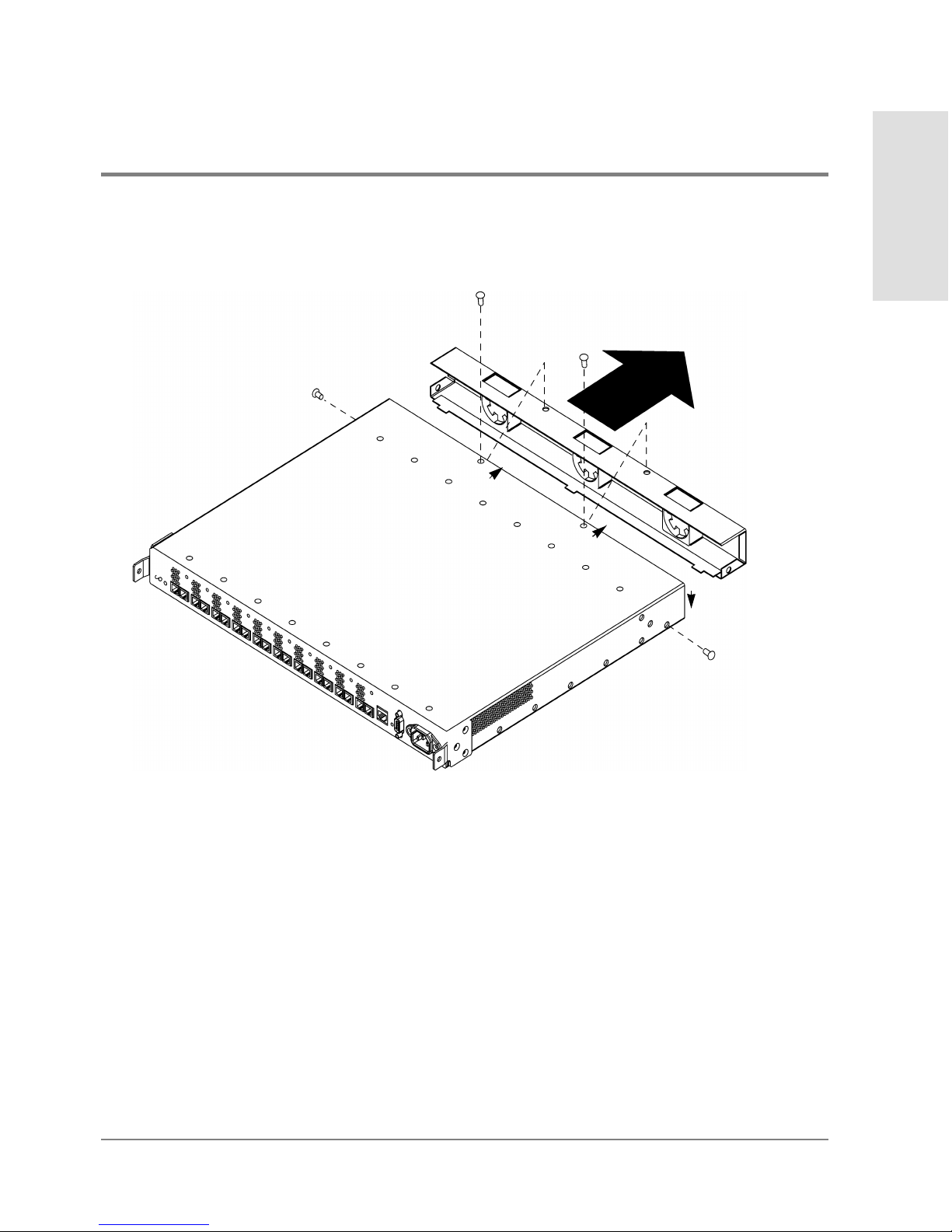
Replacing the Fan Module 89
Maintenance and
Replacement
Figure 21 Removing the Fan Module
4. Remove the fan module.
5. To insert the new fan module, line up the tabs on the bottom of the fan with the tab
openings on the hub (see Figure22 for positioning). Push the fan module into the hub.
Page 92
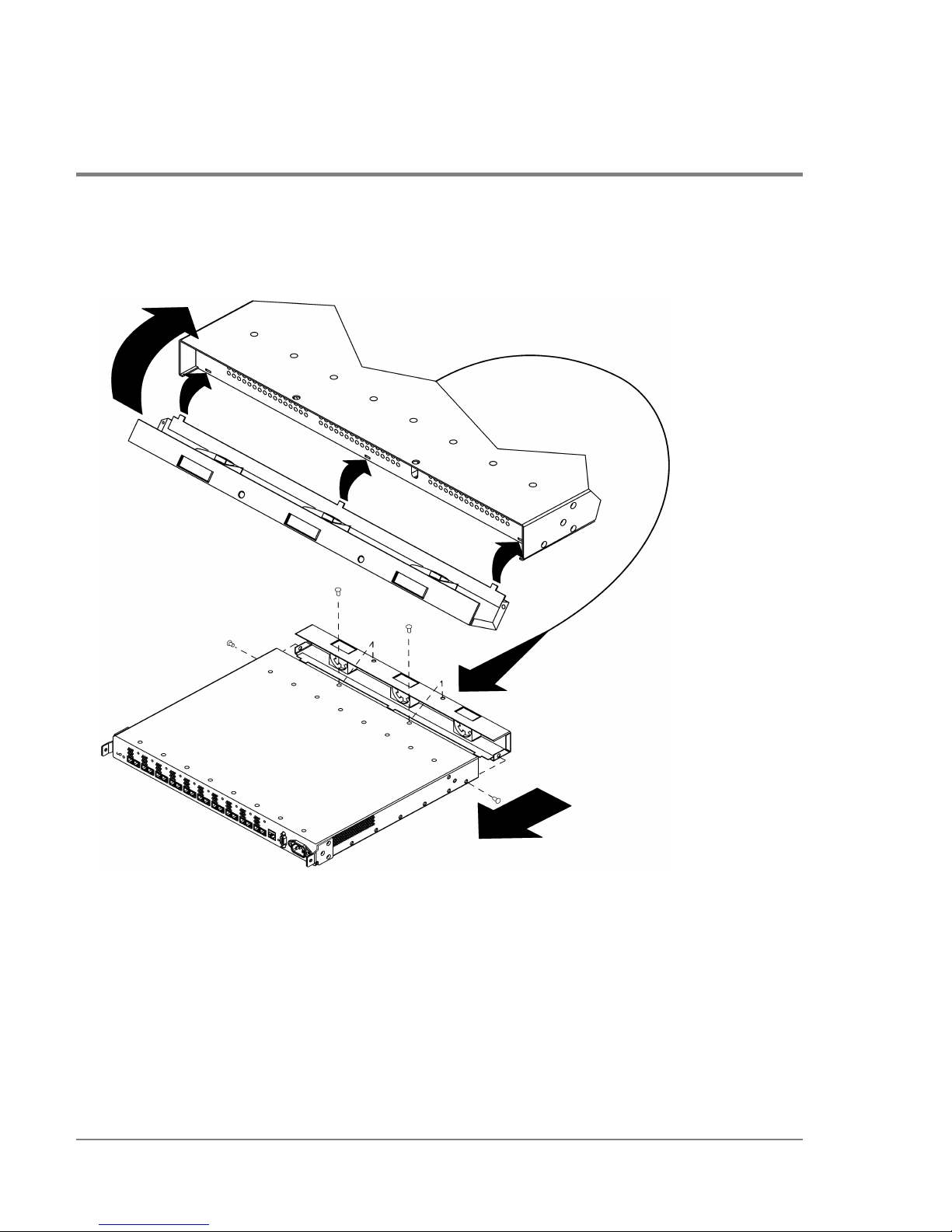
90 Replacing the Fan Module
Figure 22 Replacing the Fan Module
6. Fasten the four screws to secure the fan module.
7. Plug the power cord into the hub.
The hub powers on and runs the self-test. When the self-test is complete, the Power
LED should remain lit and the Fault LED should be off.
Page 93

Reference
91
6 REFERENCE
Standard Configurations
Configuration Options
Replacement Parts
Operating Requirements
Environmental Specifications
Physical Characteristics
Reference Documents
Regulatory Statements
Laser Safety
Page 94

92 Standard Configurations
Standard Configurations
Model S10 short-wave and model L10 long-wave hubs are available in standalone and
factory-racked configurations (Figure23 and Figure24).
The short-wave or long-wave standalone models can be ordered with a customerinstallable rackmount option for adding the hub to an existing cabinet.
Table 3 HP SureStore E Hub Product Numbers
Product Number Description
HPA3724A
Standalone short-wave hub
HP A3724AZ Factory-racked short-wave hub
HP A4839A
Standalone long-wave hub
HP A4839AZ Factory-racked long-wave hub
Page 95
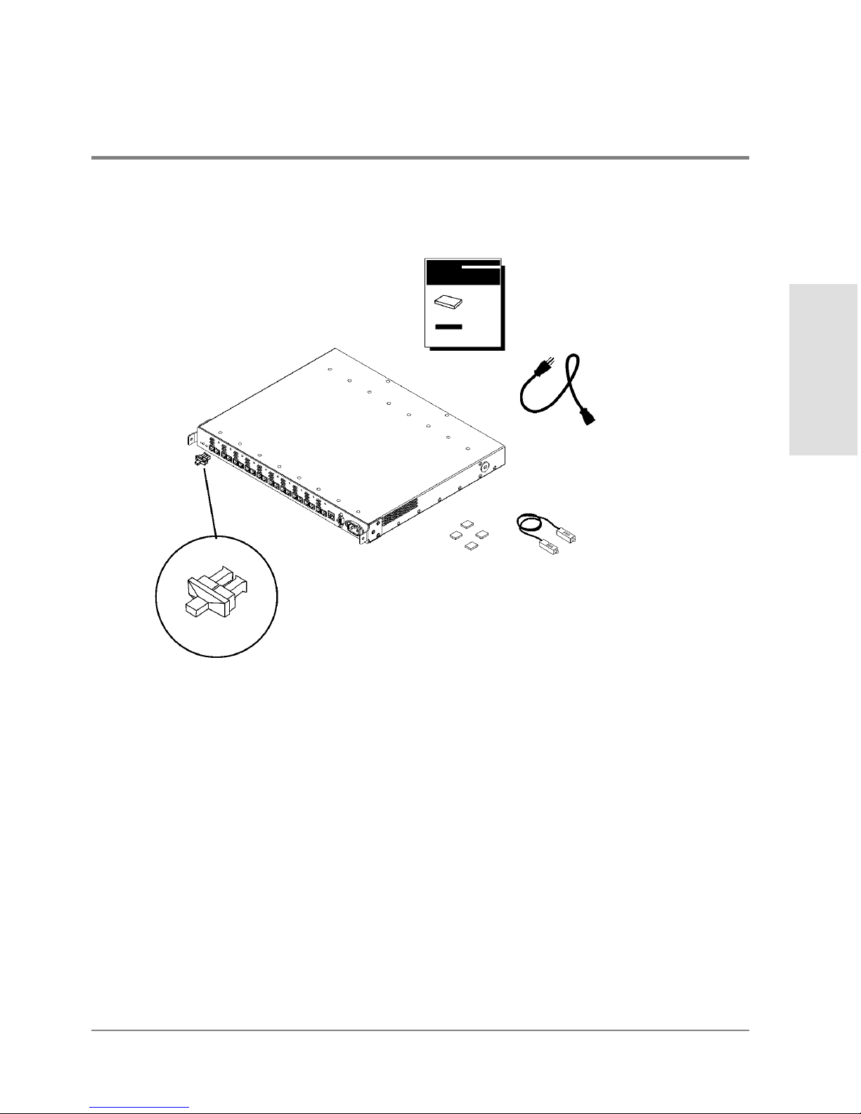
Standard Configurations 93
Reference
Figure 23 HP SureStore E Hub, Standalone
power cord
rubber feet FC-AL
loopback cable
Models S10 and L10
Service and User Manual
Installed FC
port covers
NOTE: The long-wave hub
includes an additional loopback
cable for the long-wave port.
HP SureStore E Hub
hub
Page 96
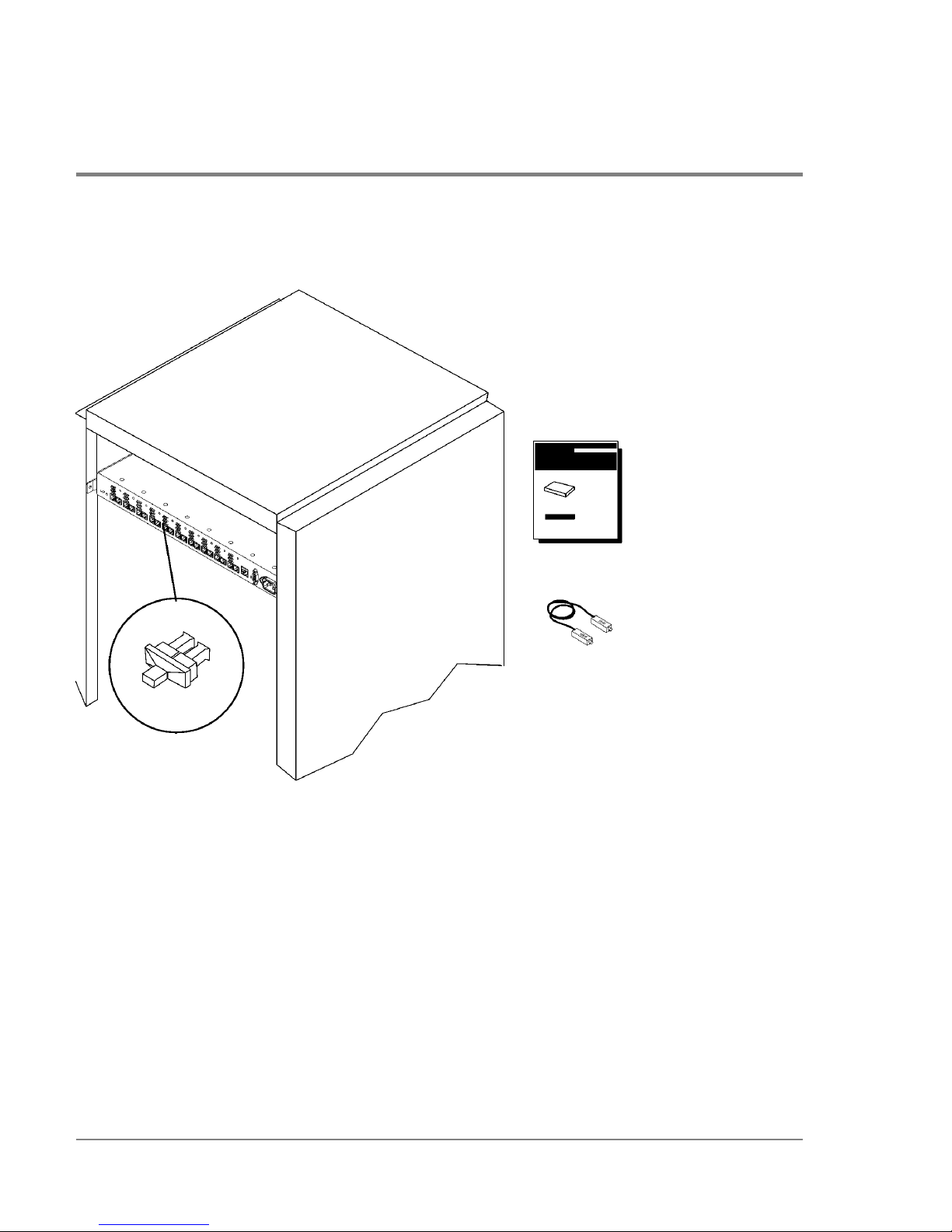
94 Standard Configurations
Figure 24 HP SureStore E Hub, Factory-Racked
HP EIA rack
FC-AL loopback cable
installed FC
port covers
hub
NOTE: The model L10 long-wave hub
includes an additional loopback
cable for the long-wave port.
Models S10 and L10
Service and User Manual
HP SureStore E Hub
Page 97

Configuration Options 95
Reference
Configuration Options
Model S10 short-wave and model L10 long-wave hubs can be ordered with the following
options:
• A customer-installable rackmount kit for adding the hub to an existing cabinet (Table4
and Figure25)
• Cables of various lengths
Fibre Channel Manager is the hub’s software management tool. This tool allows you to
remotely manage and monitor the health of the hub. Visit the Hewlett-Packard Software
Depot (http://www.software.hp.com) for more information or to download Fibre Channel
Manager at no charge.
Table 4 HP SureStoreE Hub Configuration Options
Option Description
001 Includes one rackmount kit
AFY Includes 16-m Fibre Channel cable
0Z5 Includes 50-m Fibre Channel cable
0Z6 Includes 100-m Fibre Channel cable
Page 98
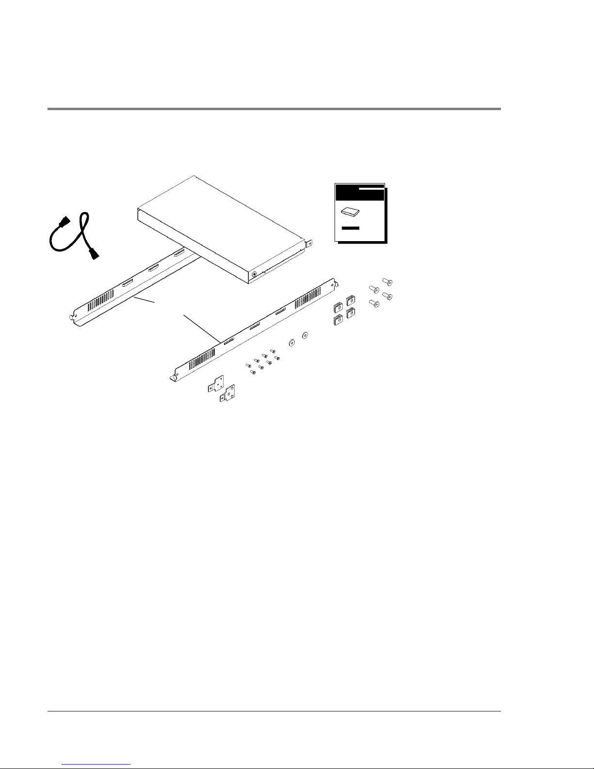
96 Configuration Options
Figure 25 Model S10 or L10 Option 001 Hub Rackmount Kit
PDU cable
plenum shroud
rails
FC-AL Hub
Rackmount Kit
Installation
Guide
10-32x.625 rail
screws
sheet metal nuts
nylon retainers
M3x.50 machine screws
mounting ear brackets
Page 99
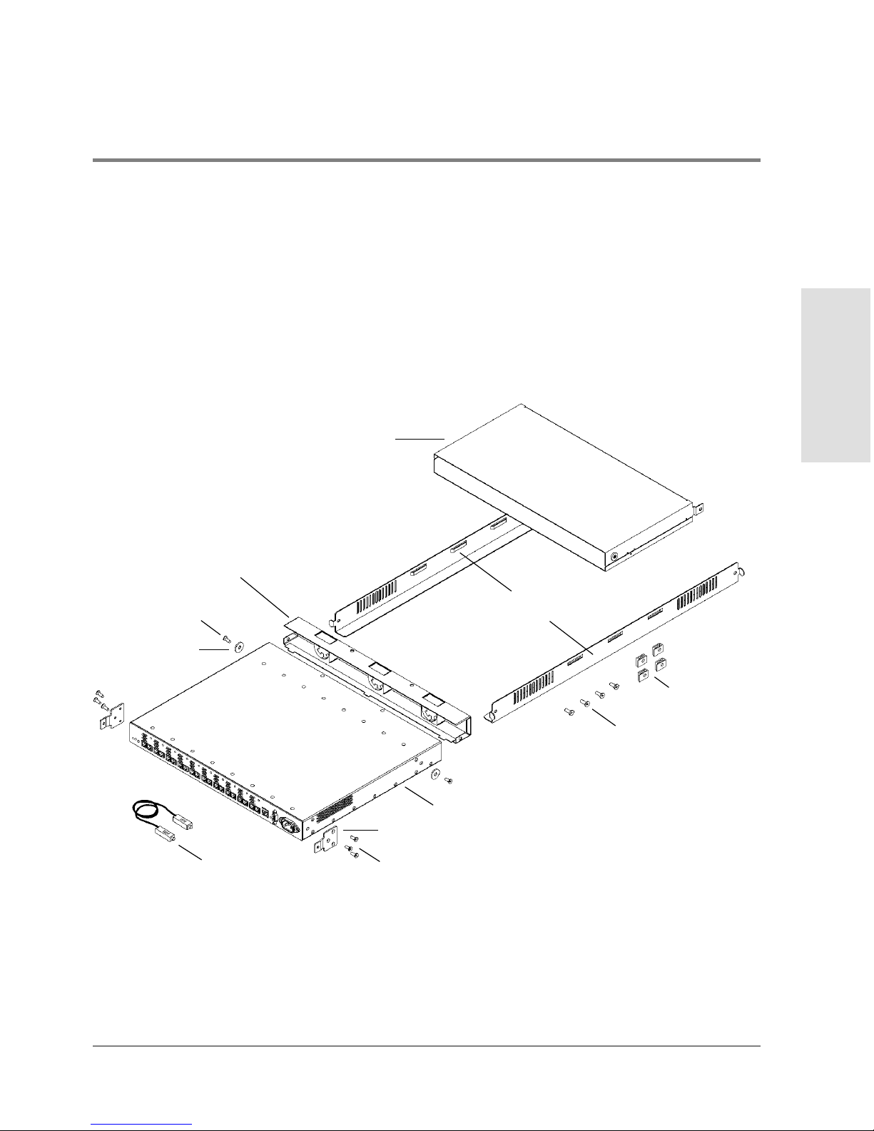
Replacement Parts 97
Reference
Replacement Parts
External parts on the hub are replaceable. The following figure and tables provide order
numbers for replaceable parts. An HP sales representative can help you obtain the part you
need.
Figure 26 HP SureStore E Hub Replaceable Parts
hub (models S10 or L10)
rails (A3724-00002)
plenum shroud
(A3724-60002)
mounting ear bracket (A3724-00001)
(A3724-60004)
fan module
sheet metal nuts
loopback cable:
nylon retainer
(A3724-0004)
(0590-0804)
10-32x.625 rail screws
(2680-0323)
M3x.5 machine screw
(0515-0914)
M3x.5 machine screws (0515-0914)
short-wave (1005-0624)
long-wave (A4839-63001)
Page 100

98 Replacement Parts
* Hewlett-Packard has tested the AMP single-mode #504655-1 SC Connector and Fujikura
Fibre Channel connector with lower metal content (as opposed to the connector with
standard metal content) for compliance to FCC Article 15 for RFI in Class A environments.
For other multi-mode lengths and specifications for single-mode cables, see Cable Plant
Specifications on page101.
Table 5 HP SureStore E Hub Replaceable Parts and Service Part Numbers
Replaceable Part Service Part Number
Mounting ear brackets A3724-00001
Rails A3724-00002
Nylon retainers A3724-00004
Fan module A3724-60002
Plenum shroud A3724-60004
Rackmount kit A3724-62001
Exchange short-wave hub A3724-69001
Exchange long-wave hub A4839-69001
FC-AL long-wave loopback cable A4839-63001
FC-AL short-wave loopback cable 1005-0624
M3 x .50 machine screws 0515-0914
Sheet metal nuts 0590-0804
10-32 x .625 machine screws 2680-0323
Table 6 Multimode Fiber Optic Cable Part Numbers
Cable Description* Customer Order Number Service Part Number
16 m, 50 micron, multimode fiber optic A3531A 1005-0586
50 m, 50 micron, multimode fiber optic A3735A 1005-0365
100 m, 50 micron, multimode fiber optic A3736A 1005-0366
 Loading...