

Page 1

HP DLT Tape Library
28/48-Slot
User’s Guide
Models A4850A and A4855A
November 1997
Print e d in U S A
© Copyright 1997 Hewlett-Packard Company
DLT and DLTtape are trademarks of Quantum
Page 2

Notice
This document contains information that is protected by copyright. All rights
are reserved. No part of this document may be photocopied, reproduced, or
translated into another lan guage. The information containe d in this
document is subject to change without notice.
See Appendix B for important safety and regulatory information.
Printing Histor y
New editions of this manual incorporate all material updated since the
previous edition. The manual printing date and part number indicate the
current editi on. The p ri n tin g d ate changes when a new edition is printed.
(Minor corrections and updates incorporated at reprint do not cause this date
to change.)
November 1997 Edition 1
ii
Page 3
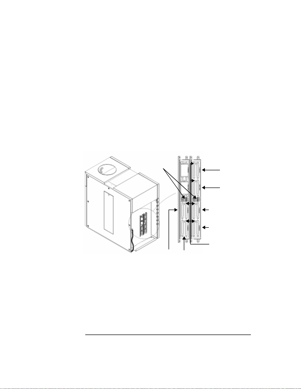
Typographical Conventions
This manual uses the following typographical conventions:
Font Used for
Italics Document titles and statements that need to be
emphasized
Typewriter Font Commands you type on your keyboard or screen
menu items you can select
COMMAND TEXT Information displayed in the display window of
the library
KEYCAP TEXT
NOTE Notes provide information that can be helpful in understanding the operation
of the product.
CAUTION Cautions call attention to an operating procedure or practice that could
result in damage to the product if not correctly performed. Do not proceed
beyond this box until you fully understand and meet the indicated
conditions.
WARNING
War nings call attention to a procedure or practice that could result in
personal injury or loss of data if not correctly performed.
proceed beyond this box until you fully understand and meet the
indicated conditions.
This warning symbol on a product label indicates that personal
injury could result if the product is used improperly, and that mo re
detailed information is given in the installation and/or user manuals.
Keys on the library control panel
Do not
iii
Page 4

iv
Page 5

Contents
1 Product De s cription
Overview. . . . . . . . . . . . . . . . . . . . . . . . . . . . . . . . . . . . . . . . . . . . . . . . . . . . . . . . 1-2
HP DLT Tape Library. . . . . . . . . . . . . . . . . . . . . . . . . . . . . . . . . . . . . . . . . . . . . . 1-3
Product Matrix. . . . . . . . . . . . . . . . . . . . . . . . . . . . . . . . . . . . . . . . . . . . . . . . . . . 1-4
Supported Platforms . . . . . . . . . . . . . . . . . . . . . . . . . . . . . . . . . . . . . . . . . . . . . . 1-5
Library Features. . . . . . . . . . . . . . . . . . . . . . . . . . . . . . . . . . . . . . . . . . . . . . . . . . 1-6
SCSI Ports . . . . . . . . . . . . . . . . . . . . . . . . . . . . . . . . . . . . . . . . . . . . . . . . . . . . . 1-8
Specifications. . . . . . . . . . . . . . . . . . . . . . . . . . . . . . . . . . . . . . . . . . . . . . . . . . . . 1-9
Quantum DLT4000 and DLT7000 Drive Mechanism Specifications . . . . . 1-9
DLT Tape Library Specifications . . . . . . . . . . . . . . . . . . . . . . . . . . . . . . . . . 1-12
DLTtape Specifications . . . . . . . . . . . . . . . . . . . . . . . . . . . . . . . . . . . . . . . . . 1-13
Environmental Specifications. . . . . . . . . . . . . . . . . . . . . . . . . . . . . . . . . . . . 1-14
DLT Tape Library Product Certifications . . . . . . . . . . . . . . . . . . . . . . . . . . 1-16
2 Library Installa tio n
Overview. . . . . . . . . . . . . . . . . . . . . . . . . . . . . . . . . . . . . . . . . . . . . . . . . . . . . . . . 2-2
Step 1: Choose a Location . . . . . . . . . . . . . . . . . . . . . . . . . . . . . . . . . . . . . . . . . 2-3
Step 2: Prepare Components . . . . . . . . . . . . . . . . . . . . . . . . . . . . . . . . . . . . . . . 2-4
Step 3: Install SCSI Cards . . . . . . . . . . . . . . . . . . . . . . . . . . . . . . . . . . . . . . . . . . 2-5
Step 4: Connect the Library to the Host . . . . . . . . . . . . . . . . . . . . . . . . . . . . . . 2-6
Step 5: Connect Power . . . . . . . . . . . . . . . . . . . . . . . . . . . . . . . . . . . . . . . . . . . . 2-8
Step 6: Configure the Host . . . . . . . . . . . . . . . . . . . . . . . . . . . . . . . . . . . . . . . . . 2-9
Moving or Shipping the Library . . . . . . . . . . . . . . . . . . . . . . . . . . . . . . . . . . . . 2-10
3 Tape Cartridges
Overview. . . . . . . . . . . . . . . . . . . . . . . . . . . . . . . . . . . . . . . . . . . . . . . . . . . . . . . . 3-2
Choosing Tape Cartridges. . . . . . . . . . . . . . . . . . . . . . . . . . . . . . . . . . . . . . . . . . 3-3
Labeling Tape Cartridges . . . . . . . . . . . . . . . . . . . . . . . . . . . . . . . . . . . . . . . . . . 3-4
Write-Protecting Tape Cartridges . . . . . . . . . . . . . . . . . . . . . . . . . . . . . . . . . . . 3-5
Maintaining Tape Cartridges . . . . . . . . . . . . . . . . . . . . . . . . . . . . . . . . . . . . . . . 3-6
v
Page 6

Contents
4 Library Operat i on
Overview. . . . . . . . . . . . . . . . . . . . . . . . . . . . . . . . . . . . . . . . . . . . . . . . . . . . . . . . 4-2
Operating the Control Panel . . . . . . . . . . . . . . . . . . . . . . . . . . . . . . . . . . . . . . . 4-3
Understanding the Display Window . . . . . . . . . . . . . . . . . . . . . . . . . . . . . . . . . 4-4
Drive Status. . . . . . . . . . . . . . . . . . . . . . . . . . . . . . . . . . . . . . . . . . . . . . . . . . . . 4-4
Status Indicators . . . . . . . . . . . . . . . . . . . . . . . . . . . . . . . . . . . . . . . . . . . . . 4-4
Activity Indicators. . . . . . . . . . . . . . . . . . . . . . . . . . . . . . . . . . . . . . . . . . . . 4-4
Control Panel Options. . . . . . . . . . . . . . . . . . . . . . . . . . . . . . . . . . . . . . . . . . . 4-5
First Level Options . . . . . . . . . . . . . . . . . . . . . . . . . . . . . . . . . . . . . . . . . . . 4-5
Second Level Options . . . . . . . . . . . . . . . . . . . . . . . . . . . . . . . . . . . . . . . . . 4-5
Entering the Administration Menu Password . . . . . . . . . . . . . . . . . . . . . . . . . 4-7
Setting a New Administration Menu Password. . . . . . . . . . . . . . . . . . . . . . . . 4-8
Specifying SCSI Addresses. . . . . . . . . . . . . . . . . . . . . . . . . . . . . . . . . . . . . . . . . 4-9
Viewing the Current SCSI Address Settings. . . . . . . . . . . . . . . . . . . . . . . . 4-10
Setting the SCSI Addresses. . . . . . . . . . . . . . . . . . . . . . . . . . . . . . . . . . . . . . 4-10
Interpreting the SCSI Bus Status Indicator LEDs . . . . . . . . . . . . . . . . . 4-12
Setting the Robotics Controller Bus Type . . . . . . . . . . . . . . . . . . . . . . . . . 4-13
Loading Cartridges Into the Library . . . . . . . . . . . . . . . . . . . . . . . . . . . . . . . . 4-14
Loading Cartridges Through the Mailslot . . . . . . . . . . . . . . . . . . . . . . . . . . 4-15
If a Tape Cartridge Will Not Load . . . . . . . . . . . . . . . . . . . . . . . . . . . . . . . . 4-16
Loading Cartridges Through the Bulk Load Access Door . . . . . . . . . . . . 4-17
Security Configurations . . . . . . . . . . . . . . . . . . . . . . . . . . . . . . . . . . . . . . 4-18
Removing Cartridges from the Library. . . . . . . . . . . . . . . . . . . . . . . . . . . . . . 4-19
Ejecting Cartridges Through the Mailslot. . . . . . . . . . . . . . . . . . . . . . . . . . 4-19
If a Tape Cartridge Will Not Eject . . . . . . . . . . . . . . . . . . . . . . . . . . . . . . . . 4-20
Removing Tape Cartridges Through the Bulk Load Access Door. . . . . . 4-21
Security Configurations . . . . . . . . . . . . . . . . . . . . . . . . . . . . . . . . . . . . . . 4-22
Cleaning the Tape Drives . . . . . . . . . . . . . . . . . . . . . . . . . . . . . . . . . . . . . . . . . 4-23
If the Cleaning Cartridge Will Not Load . . . . . . . . . . . . . . . . . . . . . . . . . . . 4-25
Drive Cleaning Issues . . . . . . . . . . . . . . . . . . . . . . . . . . . . . . . . . . . . . . . . . . 4-26
vi
Page 7

Contents
Clearing a Drive Cleaning Error. . . . . . . . . . . . . . . . . . . . . . . . . . . . . . . . . . . . 4-27
Setting a Configuration Option . . . . . . . . . . . . . . . . . . . . . . . . . . . . . . . . . . . . 4-29
Retrieving Performance Information . . . . . . . . . . . . . . . . . . . . . . . . . . . . . . . 4-32
Running an Internal Test. . . . . . . . . . . . . . . . . . . . . . . . . . . . . . . . . . . . . . . . . . 4-36
Using Online Repair. . . . . . . . . . . . . . . . . . . . . . . . . . . . . . . . . . . . . . . . . . . . . . 4-40
Troubleshooting. . . . . . . . . . . . . . . . . . . . . . . . . . . . . . . . . . . . . . . . . . . . . . . . . 4-42
Operating System-based Support Tools . . . . . . . . . . . . . . . . . . . . . . . . . . . 4-42
Running Support Tools . . . . . . . . . . . . . . . . . . . . . . . . . . . . . . . . . . . . . . . . . 4-43
DLT Drive Expert Tools. . . . . . . . . . . . . . . . . . . . . . . . . . . . . . . . . . . . . . . . . 4-44
Robotics Controller Expert Tools . . . . . . . . . . . . . . . . . . . . . . . . . . . . . . . . 4-45
Resolving Other Problems. . . . . . . . . . . . . . . . . . . . . . . . . . . . . . . . . . . . . . . 4-46
A Supplies and Accessories
Supplies and Accessories . . . . . . . . . . . . . . . . . . . . . . . . . . . . . . . . . . . . . . . . . .A-2
B Safety and Regulatory In formation
Overview. . . . . . . . . . . . . . . . . . . . . . . . . . . . . . . . . . . . . . . . . . . . . . . . . . . . . . . .B-2
Safety Information. . . . . . . . . . . . . . . . . . . . . . . . . . . . . . . . . . . . . . . . . . . . . . . .B-3
CDRH Regulations (USA Only). . . . . . . . . . . . . . . . . . . . . . . . . . . . . . . . . . . .B-3
Regulatory Information. . . . . . . . . . . . . . . . . . . . . . . . . . . . . . . . . . . . . . . . . . . .B-4
FCC Radio Frequency Interference Statement (USA Only) . . . . . . . . . . . .B-4
EC Radio Frequency Interf erence Statement (Europe Only). . . . . . . . . . .B-4
United Kingdom Telecommunications Act 1984 . . . . . . . . . . . . . . . . . . . . .B-4
EC Declaration of Conformity . . . . . . . . . . . . . . . . . . . . . . . . . . . . . . . . . . . . B-5
Herstellerbescheinigung . . . . . . . . . . . . . . . . . . . . . . . . . . . . . . . . . . . . . . . . .B-6
English Translation of German Sound Emission Directive . . . . . . . . . .B-6
Turvallisuusyhteenveto . . . . . . . . . . . . . . . . . . . . . . . . . . . . . . . . . . . . . . . . . .B-6
English Translation of Finnish Regula tory Information. . . . . . . . . . . . .B-7
Japanese VCCI Statement . . . . . . . . . . . . . . . . . . . . . . . . . . . . . . . . . . . . . . . .B-8
English Translation of Japanese VCCI Statement . . . . . . . . . . . . . . . . . .B-8
vii
Page 8

Contents
viii
Page 9

Figures
Figure 1-1 HP DLT Tape Library . . . . . . . . . . . . . . . . . . . . . . . . . . . . . . . . . . . . 1-3
Figure 1-2 Location of Library Features . . . . . . . . . . . . . . . . . . . . . . . . . . . . . . 1-6
Figure 1-3 Right Side Panel and Bulk Load Access Door. . . . . . . . . . . . . . . . 1-7
Figure 1-4 SCSI Ports . . . . . . . . . . . . . . . . . . . . . . . . . . . . . . . . . . . . . . . . . . . . . 1-8
Figure 3-1 Proper Label Position . . . . . . . . . . . . . . . . . . . . . . . . . . . . . . . . . . . . 3-4
Figure 3-2 Write-Protect Switch Settings . . . . . . . . . . . . . . . . . . . . . . . . . . . . . 3-5
Figure 4-1 Library Control Panel . . . . . . . . . . . . . . . . . . . . . . . . . . . . . . . . . . . . 4-3
Figure 4-2 Control Panel Menu Tree . . . . . . . . . . . . . . . . . . . . . . . . . . . . . . . . . 4-6
Figure 4-3 Loading Tape Cartridges Through the Mailslot. . . . . . . . . . . . . . 4-15
Figure 4-4 Loading Tape Cartridges Through the Bulk Load Acce ss Door 4-17
Figure 4-5 Remo ving Tape Cartr idges Through the Bulk Load Access Door4-21
ix
Page 10

Figures
x
Page 11

Tables
Table 1-1 DLT Tape Library Offerings. . . . . . . . . . . . . . . . . . . . . . . . . . . . . . . . 1-4
Table 1-2 Upgrade/Conversion Kits. . . . . . . . . . . . . . . . . . . . . . . . . . . . . . . . . . 1-4
Table 1-3 DLT Tape Media . . . . . . . . . . . . . . . . . . . . . . . . . . . . . . . . . . . . . . . . . 1-4
Table 1-4 Supported Platforms . . . . . . . . . . . . . . . . . . . . . . . . . . . . . . . . . . . . . 1-5
Table 1-5 DLT Drive Specifications. . . . . . . . . . . . . . . . . . . . . . . . . . . . . . . . . . 1-9
Table 1-6 Library Specifications . . . . . . . . . . . . . . . . . . . . . . . . . . . . . . . . . . . 1-12
Table 1-7 Tape Specifications . . . . . . . . . . . . . . . . . . . . . . . . . . . . . . . . . . . . . 1-13
Table 1-8 Environmental Specifications. . . . . . . . . . . . . . . . . . . . . . . . . . . . . 1-14
Table 1-9 Product Certification . . . . . . . . . . . . . . . . . . . . . . . . . . . . . . . . . . . . 1-16
Table 2-1 Location Criteria . . . . . . . . . . . . . . . . . . . . . . . . . . . . . . . . . . . . . . . . . 2-3
Table 2-2 Required Components . . . . . . . . . . . . . . . . . . . . . . . . . . . . . . . . . . . . 2-4
Table 2-3 Drive SCSI Connection Options . . . . . . . . . . . . . . . . . . . . . . . . . . . . 2-6
Table 2-4 SCSI Interface Mode Switch Settings. . . . . . . . . . . . . . . . . . . . . . . . 2-7
Table 3-1 Supported Tape Types . . . . . . . . . . . . . . . . . . . . . . . . . . . . . . . . . . . . 3-3
Table 3-2 Tape Cartridge Maintenance. . . . . . . . . . . . . . . . . . . . . . . . . . . . . . . 3-6
Table 4-1 SCSI ID Options . . . . . . . . . . . . . . . . . . . . . . . . . . . . . . . . . . . . . . . . . 4-9
Table 4-2 Default SCSI Address Settings . . . . . . . . . . . . . . . . . . . . . . . . . . . . . 4-9
Table 4-3 SCSI Status Indicators . . . . . . . . . . . . . . . . . . . . . . . . . . . . . . . . . . . 4-12
Table 4-4 Loading Tape Cartridge Error Messages . . . . . . . . . . . . . . . . . . . . 4-16
Table 4-5 Removing Tape Cartridge Error Messages . . . . . . . . . . . . . . . . . . 4-20
Table 4-6 Error Messages When Loading Clean in g Cartridges . . . . . . . . . . 4-25
Table 4-7 Drive Cleaning Issues. . . . . . . . . . . . . . . . . . . . . . . . . . . . . . . . . . . . 4-26
Table 4-8 Configuration Options . . . . . . . . . . . . . . . . . . . . . . . . . . . . . . . . . . . 4-29
Table 4-9 Information Logs. . . . . . . . . . . . . . . . . . . . . . . . . . . . . . . . . . . . . . . . 4-32
Table 4-10 Tests Available from the Control Panel . . . . . . . . . . . . . . . . . . . . 4-37
Table 4-11 Support Tool Characteristics . . . . . . . . . . . . . . . . . . . . . . . . . . . . 4-42
Table 4-12 Drive Expert Tool Commands . . . . . . . . . . . . . . . . . . . . . . . . . . . 4-44
Table 4-13 Robotics Controller Expert Tool Commands. . . . . . . . . . . . . . . 4-45
xi
Page 12

Tables
Table 4-14 Troubleshooting . . . . . . . . . . . . . . . . . . . . . . . . . . . . . . . . . . . . . . . 4-47
Table A-1 Basic Supplies and Accessories. . . . . . . . . . . . . . . . . . . . . . . . . . . . A-3
xii
Page 13

1Product Description
1-1
Page 14

Product Description
Overview
Overview
• HP DLT T ape Library
• Product Matrix
• Supported Platforms
• Library Features
• Specifications
1-2
Page 15

HP DLT Tape Library
• Fully automated
• State-of-the-art patented HP robotics
• Industry-leading data availabilit y
• Industrial-strength durability
• User-maintenance-free library system
Tab le 1-1 on page 1-4 describes available configurations.
Figure 1-1 HP DLT Tape Library
Product Description
HP DLT Tape Library
Product Description
1-3
Page 16

Product Description
Product Matrix
Product Matrix
Table 1-1 DLT Tape Library Offerings
Library Mode l HP Product Number Drives Slots
DLT 4000 2/28 A4850A #402 Two DLT4000 28
DLT 4000 4/28 A4855A #404 Four DLT4000 48
DLT 7000 2/28 A4850A #702 Two DLT7000 28
DLT 7000 4/48 A4855A #704 Four DLT7000 48
Table 1-2 Upgrade/Conversion Kits
Upgrade Kits HP Product
Number
DLT 4000 2-Drive/Capacity Upgrade Kit A4862A DLT4 000 2/28 DLT4 000 4/48
DLT 7000 2-Drive Conversio n Kit * A4863A DLT4 000 2/28 DLT7 000 2/28
DLT 7000 2-Drive/Capacity Upgrade Kit A4864A DLT7 000 2/28 DLT7 000 4/48
* To convert a DLT4000 4/48 to a DLT7000 4/48, order tw o DLT7000 2-Drive
Conversion Kits (A4863A).
Table 1-3 DLT Tape Media
Media HP Product Number
HP DLTtape Type III XT C5141A
HP DLTtape Type IV C5141F
Cleaning Cartridge C5142A
Upgrades/
Converts
To
1-4
Page 17

Supported Pl atforms
Table 1-4 Supported Platforms
Product Description
Supported Platforms
Product Description
Servers
Workstation
On supporting platforms, the library can be connected to an HP Fibre
Channel SCSI multiplexer (HP A3308A and HP A3511A/Z) and thereby benefi t
from Fibre Channel speed and dis t an ce. The FC-SCSI multiplexer is
supported on K, T, and V platforms running HP-UX 10.20 TFC or higher.
(Consult an HP sales representative for the latest information.)
D-Class
E-Class
K-Class
Nova
T-Class
V-Class
J-Class
1-5
Page 18

Product Description
Library Features
Library Features
Figure 1-2 Location of Library Features
Front Panel Back Panel
1.
Mailslot
2.
Power switch
3.
Front and back lower panels
4.
Power connector
5.
SCSI ports
6.
SCSI interface mode switches
settings for each SCSI bus.
7.
SCSI bus indicators
indicator.
8.
Control panel
operations.
1-6
is used to load and unload single tape cartridges.
turns power to the unit on and off.
cover the front and back of the library.
connects the power cord to the library.
allow connection of the library to the host using SCSI cables.
specify termination and term power
indicate SCSI bus status. Each SCSI bus has an
displays messages and allows selection of library
Page 19
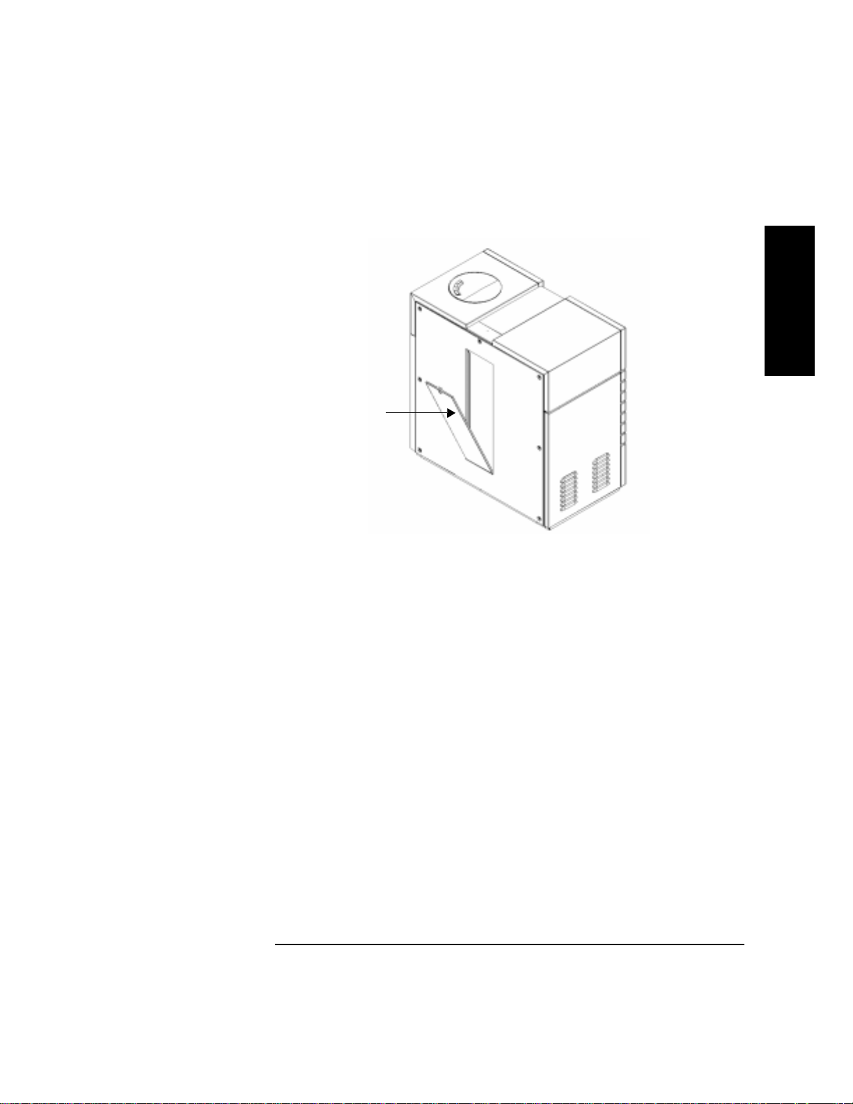
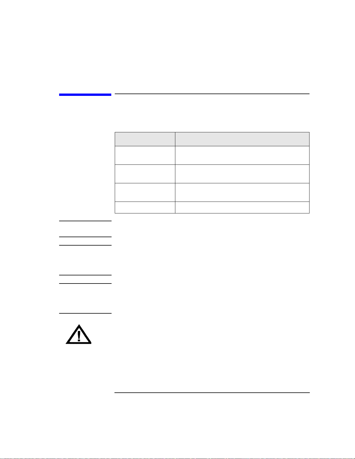
Figure 1-3 Right Side Panel and Bulk Load Access Door
Unlock with key and remove
the bulk load access door to
load multiple tape cartridges.
Product Description
Library Features
Product Description
1-7
Page 20
Product Description
Library Features
SCSI Ports
SCSI ports allow connection of the library to a host using SCSI cables. Each
SCSI port has its own bus.
The SCSI interface mode switches specify term power and termination
settings.
Single-ended/differential mode for the library bus (bus 0) is set from the
control panel (see “Setting the Robotics Controller Bus Type on page 4-13 for
details). All drive buses are differe nti al.
Figure 1-4 SCSI Ports
SCSI Interface
mode
switches
Differential
Library bus
Bus 0
Single ended
Drive 1 bus
Bus 1
Drive 2 bus
Bus 2
SCSI bus status
indicator LEDs
Drive 3 bus
Bus 3
(four-drive
library only)
All drive buses are differential
Drive 4 bus
Bus 4
(four-drive
librar y o nl y)
1-8
Page 21
Specifications
Quantum DLT4000 and DLT7000 Drive
Mechanism Specifications
Table 1-5 DLT Drive Specifications
Characteristic DLT4000 DLT7000
Performance
Product Description
Specificati ons
Product Description
Read/write transfer
rate:
maximum
sustained (DLTtape
Type IV)
Average access time 68 seconds 60 seconds
Rewind 45 seconds (average)
Loading time to
BOT (for
previously written
tape)
Unloading time to
BOT
External Interface 8-bit SCSI-2, differential 16-bit fast/wide SCSI-2, differential
Internal Interface 8-bit SCSI-2, single-ended 16-bit fast/wide SCSI-2, single-ended
Read-write head 2-channel, fer rite w/MIG 4-channel, ferrit e w/ MIG
Recording format 128 track serial serpentine variable
non-compressed mode:
1.5 MB/second
compressed (2:1 typical):
3.0 MB/second
90 seconds (maximum)
48 seconds (average) 48 seconds (average)
17 seconds (average) 17 seconds (average)
block (64 pairs)
256-tpi track density
non-compressed mode:
5.2 MB/second
compressed (2:1 typical):
10.0 MB/second
60 seconds (average)
120 seconds (maximum)
208 track serpentine (52 quads)
416-tpi track density
Data compress
algorithm
DLZ DLZ
1-9
Page 22

Product Description
Specifications
Table 1-5 DLT Drive Specifications (Continued)
Characteristic DLT4000 DLT7000
Reliability
Soft read error rate
Soft write error rate
Hard read error rate
Hard write
7
1 in 10
bytes minimum
(read as one error maximum
allowable in 10
7
of data read
minimum)
6
1 x 10
bytes minimum 1 x 106 bytes minimum
17
1 x 10
bytes minimum 1 x 1017 bytes minimum
Not allowed Not allowed
7
1 in 10
bytes minimum
(read as one error maximum
allowable in 10
minimum)
error rate
Undetected
1 x 10
30
bits read 1 x 1027 bits read
error rate
MTBF 80,000 hours 200,000 hours
Head life 10,000 hours 30,000 hours
Power Specifications
Total Power
consumption
5 volt supply 5.0 V +/- 5% (maximum)
22 W (average)
33 W (m a x i m u m)
@2.5 A (average) ,
3.0 A (maximum)
37 W (average)
47 W (maximum)
5.0 V +/- 5% (maximum)
@3.6 A (average),
3.8 A (maximum)
7
of data read
12 volt supply 12.0 V +/- 5%
@ 0.8 A (average),
1.5 A (maximum)
1-10
12.0 V +/- 5%
@ 1.6 A (average),
2.6 A (maximum)
Page 23

Table 1-5 DLT D rive Specifications (Continued)
Characteristic DLT4000 DLT7000
Physical Specifications
Product Description
Specificati ons
Product Description
Form factor 5 1/4 in. (height with modified
depth)
5 1/4 in. (height with modified
depth)
Height 3.25 in. (w/o bezel) 3.25 in. (w/o bezel)
Width 5.7 in. (behind bezel) 5.7 in. (behind bezel)
Depth 9.0 in. (measured from back of front
bezel)
9.0 in. (measured from back of front
bezel)
We ight (net) 6 lb 7 oz 6 lb 7 oz
1-11
Page 24

Product Description
Specifications
DLT Tape Library Specifications
Table 1-6 Library Specifications
Characteristic A4850A and A4855A Libraries
Performance
A verage tape
access
A verage tape
exchange
Interface SCSI-2 (single ended or differential)
MTBF 100,000 hours
MSBF (robotics) 1 million swaps
Preventive
maintenance
Total power
consumption
Line voltage 100 - 127/
Line frequency 50 to 60 Hz
Height 914 mm (36 in.)
<12 seconds
24 seconds (mean time to eject tape from drive, robotically exchange tape
from magazine and reload drive)
Reliability
None required
Power Requirements
200 W (typical) NOTE: After 30 minutes of non-operation,
260 W (maximum) the library oper ates in reduced power mode.
200 - 240 Vac
Physical Specifications
Width 863 mm (33. 9 in .)
Depth 482 mm (19 in.)
W eigh t (net) 100 kg (220 lbs)
W e igh t (packaged) 127 kg (280 lbs)
1-12
Page 25

DLTtape Specifications
Table 1-7 Tape Specifications
Characteristic DLTtape Type III XT DLTtape Type IV
Product Description
Specificati ons
Product Description
Formatted capacity 15 GB
(non-compresse d)
30 GB
(2:1 typical compression)
20/35 GB
(non-compressed)
40/70 GB
(2:1 typical compression)
Basic description 0.5 in . (metal part icle) 0.5 in. (metal par t icle)
Tape length 1167 ft 1778 ft
Cartridge
4.1 in. x 4.1 in. x 1.0 in. 4.1 in. x 4.1 in. x 1.0 in.
dimensions
Shelf life
30 years (min) @ 20
40% RH
(non-condensing)
Usage 1,000,000 passes (min)
10,0 00 lo a d s/unlo a d s (min)
o
C
30 years (min) @ 20o C
40% RH
(non-condensing)
1,000,000 passes (min)
10,000 loads/unloads (min)
1-13
Page 26

Product Description
Specifications
Envir onmental Specifications
Table 1-8 Environmental Specifications
Characteristic Tape/Drive DLT Tape Library
Temperature and Humidity
Operating 10° to 40° C
20% to 80% RH
(drive, non-condensing)
40% to 60% RH
(tape, non-condensing)
Non-operating
w/o disk
Storage/shi pmen t -40° to 66° C (drive)
Archive 18° to 28° C
Operating 0 to 30,000 ft N/A
Non-operating 0 to 50,000 ft N/A
0° to 55° C
10% to 95% RH (non-condensing)
16° to 32° C (tape)
10% to 95% RH (non-condensing)
40% to 60% RH (non-condensing)
Gradient
10° C/hour 10° C/hour
Altitude
Shock
10° to 40° C
10% to 90% RH (non-condensing)
-40° to 60° C
10% to 95% RH (non-condensing)
-30° to 60° C
(<14 consecutive days)
-30° to 60° C
(<14 consecutive days)
Operating 60 half sine shock impulses of 5 g’s
for 11 seconds in 3 axes
Non-operating half sine, 55 g, 11 ms
half sine, 140 g, 2 ms
half sine, 15 g, 20 ms
half sine, 150 g, 3 ms
half sine, 40 g, 11.8 ms
(all measured in 6 axes)
1-14
4-in. half sine edge drop, 4 faces
30 g
(trapezoidal wave, edge drop)
Page 27

Table 1-8 Environmental Specifications (Continue d)
Characteristic Tape/Drive DLT Tape Library
Package shock
Product Description
Specificati ons
Product Description
Drop tests 42 in. (packaged drive dropped on six
sides, three edges, one corner)
Vibration
Operating random 5 - 500 Hz @ 1 grms
10 minutes, 3 axes
Operating sine 0.25 g peak 10 - 300 Hz
0.1 g peak 300 - 500 Hz
10 - 500 - 10 Hz @ 1/4 octave/minute in
3 axes
Non-operating
random
Non-operating
swept-sine
5 - 500 Hz @ 2 grms
60 minutes, 6 axes
5 - 10 Hz @ 0.5 g peak
10 - 50 Hz @ 1 g peak
50 - 500 Hz @ 3 g peak
5 - 500 - 5 Hz @ 1/2
octave/minute in 6 axes
Non-operating
random packaged
Non-operating
swept si ne
packaged
2 - 200 Hz @ 1.5 grms
6 axes, dwell = 30 m
5 - 150 Hz @ 0.5 g peak
5 - 150 - 5 Hz @ 1/2 oct/min, 6 axes
with d w e l l at lo west nat ural
resonance in each axes
12-in. drop, 5 faces
0.21 grms
N/A
2.1 grms
0.5 grms (0 to peak)
1.49 grms, top-to-bottom
0.5 G (0-pk), 3 - 200 - 3 Hz 1
oct/min, 1 axis (top-to-bottom)
Acoustic Emission
Media exchange N/A 6.5 Bels
Read/write
4.3 Bels (maximum) A-weighted 6.5 Bels
operation
1-15
Page 28

Product Description
Specifications
DLT Tape Library P r oduct Cert ifications
Table 1-9 Product Certification
Safety EN60950/IEC 950
Electromagnetic
emissions
Laser EN60825 (1994)/IEC 825 (1993) +A1, Laser Class 1
EN55022/CISPR - 22, Class A
EN50082 - 1
EN55024 - 2/IEC 1000 - 4 - 2, 4kV CD,
8kV AD
EN55024 - 3/IEC 1000 - 4 - 3, 3 V/m
EN55024 - 4/IEC 801 - 4,
1kV Peak Power l ines
0.5 kV Signal lines
FCC 47 CFR Part 15 - Cla ss “A”
VCCI Class A
EN61000 - 3 - 2/IEC 1000 - 3 - 2
EN61000 - 3 - 3/IEC 1000 - 3 - 3
1-16
Page 29

2 Library Installatio n
2-1
Page 30

Library Installation
Overview
Overview
To install the library:
1. Choose a location.
2. Prepare the necessary components.
3. Install the SCSI cards.
4. Connect the library to the host.
5. Connect power.
6. Configure the host .
This chapter also explains how to move or ship the library.
NOTE Installation must be performed by HP qualified personnel.
2-2
Page 31

Step 1: Choose a Location
Choose a location that meets the following criteria. Take the library there
before unpacking it.
Table 2-1 Location Criteria
Characteristic Requirement
Library Installation
Step 1: Choose a Location
Room temperature 50°-104° F (10°-40° C)
Power source AC power voltage: 100-127/200-240 V
Air quality Minimal so urces of particulate contamination . Avoid areas near frequently
used doors and walkways, stacks of supplies that collect dust, and
smoke-filled rooms.
CAUTION: Excessive dust and debr is can damage tapes and tape drives .
Adequate
clearance
Positioning the
library depends on
how it will fit in
the computer
room.
Placed in a row of peripherals
with the mailslot facing out:
Fron t 86 c m ( 3 4 in.) for operato r
access
Back 56 c m ( 2 2 in.) fo r co o ling
and service
Sides Adjacent to other cabinets;
roll library out to access
the bulk load access door
wall
Back
Bulk load
access
Free standing/against a wall:
Front 61 cm (24 in. ) for operator
access
Back 61 cm (24 in.) for service
access
Sides 30.5 cm (12 in.) for service,
operator access, and
cooling; roll library out to
access the bulk load access
door
wall
Bulk load
access
Back
Mailslot
Front
Library Installatio n
Mailslot Front
2-3
Page 32

Library Installation
Step 2: Prepare Components
Step 2: Prepare Components
Make sure all required components are available.
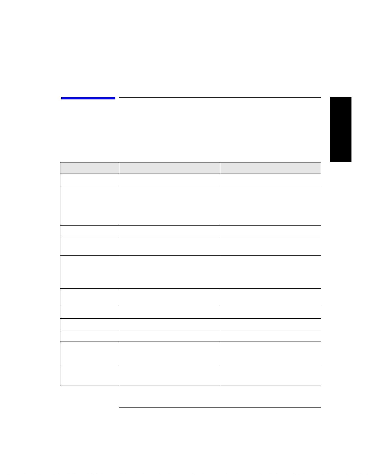
Table 2-2 Required Comp onents
Component Installation Notes
Library Do not unpack the library until it is in the
proper location.
SCSI cards Required number of cards installed in host depends on
library configuration. Connect drives to differential
fast/wide SCSI cards. Connect robotics controller to a
fast/wide differential or a single-ended SCSI card.
SCSI cables Required number of cables (68-pin) is one per drive and
one for the robotics controller. Maximum cable length
(total) is 25 meters if connected to a differential SCSI
card and 6 meters for a single-ended SCSI card.
Power cord Power cord is included wit h library.
Data cartridge One HP DLTtape IV data cartridge is included with
library.
Cleaning
cartridge
If any components are missing, contact a sales representative.
2-4
Cleaning cartridge is included with library.
Page 33

Library Installation
Step 3: Install SCSI Cards
Step 3: Install SCSI Cards
Install the single-ended or differential SCSI cards into the host.
Refer to the host user manual and the card installation instructions for
information on inst alling the cards.
Library Installatio n
2-5
Page 34

Library Installation
Step 4: Connect the Library to the Host
Step 4: Connect the Library to the Host
1. Ensure that the host has been properly shut down and powered off.
2. Remove the back panel (lift up on the bottom of the panel, then pull
it away).
3. Use SCSI cables to connect the drives to the host, as explained in the
following table.
Table 2-3 Drive SCSI Connection Options
Library Mo del SCSI Configuration
Non-daisy chaine d Daisy chained
DLT4000 2/28 Connect drive ports 1 and 2 to
their own host SCSI cards.
Connect drive ports 1 and 2 together;
connect to a single host SCSI card.
DLT4000 4/48 Connect drive ports 1, 2, 3, and
4 to their own host SCSI cards.
DLT7000 2/28 Connect drive ports 1 and 2 to
their own host SCSI cards.
DLT7000 4/48 Connect drive ports 1, 2, 3, and
4 to their own host SCSI cards.
4. Connect the library (bus 0) to a dedicated host SCSI card.
NOTE Connecting other peripherals to the library or drive buses is not supported.
Connect drive ports 1 and 2 together;
connect to a single host SCSI card.
Connect drive ports 3 and 4 together;
connect to a single host SCSI card.
Not supported
Not supported
2-6
Page 35

5. For each bus, set the SCSI interface mode switch as follows.
Table 2-4 SCSI Interface Mode Switch Settings
Setting Purpose Set to
Library Installation
Step 4: Connect the Library to the Host
CAUTION
Term Pwr Sends termination
ON
power to the bus
Termination Terminates the SCSI
bus; functions the same
as a physical
terminator
Do not use a physical term inat or.
If a physical terminato r is attach ed an d
ON if one port on the bus is
open
OFF if both ports on the bus
are connected to a cable
termination is set to ON, the bus will be overterminated, which could cause
the device to function incorrectly.
Library Installatio n
2-7
Page 36

Library Installation
Step 5: Connect Power
Step 5: Connect Power
Use the power cord shipped with the library.
1. Make sure the power switch on the front of the library is switched off.
2. Plug the power cord into the power port on the back of the library.
3. Plug the other end of the power cord into a three-hole grounded outlet.
4. Turn on the power switch.
SELF TEST and NOT READY alternately appear in the dis play wind ow on
the library. Once the power on test completes (approximately 3 minutes),
the drive status information appears in the display window. (See
“Understanding the Display Window” on page 4-4.)
NOTE If the drive status information does not display, the power on test was not
successful and DEVICE FAILED displays. For troubleshooting procedures,
see “Troubleshooting” on page 4-41.
5. Turn on power to the host.
2-8
Page 37

Library Installation
Step 6: Configure the Host
Step 6: Configure the Host
Configuring th e lib r ary on the host includes An HP qualifi ed service
representative must configure the library on the host. This procedure
includes installing drives, creating device files an d verifying the
configuration.
Library Installatio n
2-9
Page 38

Library Installation
Moving or Shipping the Library
Moving or Shipping the Library
To move or ship the library:
1. Properly shut down and power off the host.
2. Remove the cartridges (see s of t ware package documentation).
3. Verify that the drives are empty ( displays after th e drive number).
4. Turn off the power switch on the front of the library.
5. Remove the back cosmetic panel (lift up on the bottom of the panel, then
pull it away).
6. Remove the power cord and the SCSI cables.
7. Raise the leveler feet (use a 1/2-inch wrench).
8. Tran s p o rt the l ib rary:
• To move the library a short distance, carefully roll the library to its
new destination.
• To ship the library, repackage the library in the same materials and
ship it in the same manner in which it was received, then unpack it at
its new destination.
CAUTION The library can be seriou sly damaged if it is not shipped usi n g appro priate
shipping mater ials. A servi ce representativ e can provide ass istance or advice
on how to best repackage and ship the library.
9. Lower the leveler feet.
10. Re-install the library. Refer to installation steps 3 throug h 6 in this
chapter .
2-10
Page 39

3 Tape Cartridges
3-1
Page 40

Tape Cartridges
Overview
Overview
• Choosing Tape Cartridges
• Labeling Tape Cartrid ges
• Write-Protecting Tape Cartridges
• Maintaining Tape Cartridges
3-2
Page 41

Tape Cartridges
Choosing Tape Cartridges
Choosing Tape Cartridges
Table 3-1 Supported Tape Types
Cartridge Type Available Densities
HP DLTtape IV Data Cartridge 20 GBytes (DLT4000 drive)
35 GBytes (DLT7000 drive)
HP DLTtape III XT Data Cartridge 15 GBytes
NOTE Hewlett-Packard rec ommends using the HP DLTtape IV Data Cartr idge. (See
Appendix A for ordering information.)
3-3
Ta pe C art ridg es
Page 42

Tape Cartridges
Labeling Tape Cartridges
Labeling Tape Cartridges
Make it a practice to use bar code labels on the tape cartridges. The host
software may need to keep track of the following information and the
associated bar code:
• date of format or initialization
• cartridge owner (such as group or department)
• storage purpose (such as backup, old version of operating system)
If the host software does not keep track of this information, create a method
of doing so.
Slide the label into the sl ot on the face of the cartridge as illustr ated in Figure
3-1.
NOTE If bar code labels are not used and the Barcode On/Off configuration is set to
On, the Inventory C heck tes t perfo rmance can be signifi cantl y im pacted. Thi s
test runs when the library is powered on and whenever the bulk load access
door is used.
See Appendix A for information about ordering additional bar code labels.
Figure 3-1 Proper Label Position
3-4
Page 43

Tape Cartridges
Write-Protecting Tape Cartridges
Write-Protecting Tape Cartrid ges
The use of the write protect switch ensur es data safety for files that have
been previously wri tten t o the tape and prevents any additional files from
being written to the tape.
To change the write-protect setting,
• Left to
prevent
data from being written to the cartridge. The orange
indicator on the cartridge can be seen when the write- p rotect switch is in
the “ON” position (see “A” in Figure 3-2).
•Right to
data to be written to the cartr idge. The or ange i ndicator on
allow
the cartridge cannot be seen when the write-protect switch is in the
“OFF” position (see “B” in Figure 3-2).
With the write-protect switch in either position, data can be read from the
cartridge.
Figure 3-2 Write-Prote ct Switch Settings
Write-Protected
move the write-protect switch:
Ta pe C art ridg es
Not Write-Protected
3-5
Page 44

Tape Cartridges
Maintaining Ta pe Cartridges
Maintaining Tape Cartridges
Table 3-2 Tape Cartridge Maintenance
DO NOT Do
• Expose cartridges to magnetic fields.
• Leave cartridges in the tape drive when library
power is off.
• Expose cartridges to extreme temperatures or
extreme humidity. Acceptable operating
temperatures range from 10- 40° C (50-104° F).
Acceptable storage temperatures range from
16-32° C (60-90° F). Accep table operati ng humidity
ranges from 20-80%; acceptable storage humidity
ranges from 10-95%.
• Expose cartridges to moisture or direct sunlight.
• Drop the cartridges or carry them in a loose
container that could submit the cartr id ges to any
unnecessary physical shock.
• Open cartridges lid, exposing the tape to possible
contamination or physical damage.
• Touch the tape surface.
• Take cartridges apart.
• Use graphite pencils, water soluble felt pens, or
other debris-producing writing instruments to
label cartridges.
• Store cartridges in a clean, safe
place in their protective plastic
containers when not in use.
• Remove dust on the outside of
cartridges using a damp cloth.
(Older, frequently used tapes may
build up dust.)
• Store cartridges vertically, not flat.
• Store cartridges intended for
archiving data in th eir plastic
containers and in environmental
conditions of 18-28° C (64-82° F)
and 40-60% relati ve h umidity.
• Use labels like th ose include d in the
accessories kit or that meet the
specifications listed in Appendix A
Supplies and Accessories.
• Erase a label; replace it instead.
3-6
Page 45

4 Library Operation
4-1
Page 46

Library Operation
Overview
Overview
• Operating the Control Panel
• Understanding the Display Window
• Entering the Administration Menu Password
• Setting a New Administration Menu Password
• Specifying SCSI Addresses
• Loading Cartridges Into the Library
• Removing Cartridges from the Library
• Cleaning the Tape Drives
• Clearing a Drive Cleaning Error
• Setting a Configuration Option
• Retrieving Perf orm ance Information
• Running an Internal Test
• Using On-line Repair
• Troubleshooting
4-2
Page 47

Operating the Control Panel
Figure 4-1 Library Co ntrol Panel
Library Operation
Operating the Control Panel
1.
Swivel Feature
allows the control panel to face either the front or side
of the library.
2.
Activity Li gh
t indicates the following:
• Steady Green – power is on.
• Flashing Green – a tape cartridge is be in g accessed.
• Amber – fault indicator.
3.
16-Character Display
displays information about the current operation
or drive status.
An asterisk (*) indicates there is a menu beneath the option. Press
to access the menu. Press
4.
Selection Buttons
•
•
CANCEL
PREV
cancels the current operation or option.
scrolls the display options backward by one. When held
NEXT
perform the following operations:
or
PREV
to display the menu options.
continuously, the options scroll quickly.
NEXT
•
scrolls the display options forward by one. When held
continuously, the options scroll quickly.
ENTER
•
selects the displayed option.
ENTER
Libr ary Operation
4-3
Page 48

Library Operation
Understanding the Display Window
Understanding the Display Window
The display window displays drive status indicators and menu options.
Drive Status
Drive status displays when the library is in the “r ead y” state. For example:
Drive number
Status indicator
Activity indicat or
The library has two or four drives,
depending on the model.
1 2 3 4
In this example:
• Drive 1 has a cartridge insert ed and data is bei n g written to the tape.
• Drive 2 is empty.
• Drive 3 has a cartridge ins erted; the tape is being searched f orward.
• Drive 4 has a write-protected cartridge inserted.
P
Status Indic ators
The drive is full.
The drive is empty.
The drive needs to be cleaned .
C
The tape cartridge in th e drive is write-protected.
P
Blank – The drive is off-line.
Activity Indicat or s
The activity light flashes during the following operations:
Information is being written to the tape in the drive.
Information is bein g read from the tape in the drive.
The tape in the drive is being searched backward or is rewinding.
The tape in the drive is being searched forward.
C
The drive is being cleaned.
4-4
Page 49

Contro l Panel Optio ns
Library Operation
Understanding the Display Window
Press
PREV
or
NEXT
while the library is in the “ready” state to display first
level options. Access second level options from ADMIN* (second level
options require a password; see “Entering the Ad ministration Menu
Password” on page 4-7).
An asterisk (*) indicates that the option has multiple selections.
or
ENTER
to select the option or display
NEXT
to display other available options.
When a menu selection is flashing, press
the option’s selections. Press
PREV
First Level Options
LOAD* Lo ad s tape cartridges into the library storage slots.
EJECT* Ejects tape cartridges stored inside the library.
RELEASE DOOR Allows the bulk load access do or to be unlock ed.
ADMIN* Accesses second-level options.
Second Level Options
INFO* Disp lays perform anc e information stored in the
library.
TEST* Runs internal library tests.
CONFIG* Custo mizes the way the library functions.
CLEAN DRIVES* Displays the drive numbers to clean.
OVERRIDE DOOR* Opens door when tapes are in drives.
SCSI IDs* Sets the SCSI addresses for the robotics controller
and the library drive mechan isms.
ONLINE REPAIR* Deactivates a drive for replacement.
Libr ary Operation
4-5
Page 50

Library Operation
Understanding the Display Window
Figure 4-2 Control Panel Menu Tree
1 2 3 4
Drive Status Indicators
drive need s to be cleaned
C
P
tape is write-protected
drive is empty
drive is fu ll
(blank) drive is off-line
drive is being cleaned
C
↓
drive is writing to tape
drive is reading from tape
searching tape forward
<<
searching tape backward
PREV/NEXT
LOAD * EJECT *
LOAD SLOT 1
...
LOAD SLOT 48
LOAD DRIVE 1
...
LOAD DRIVE 4
LOAD CLEANING
PREV/NEXT PREV/NEXTPREV/NEXT
ENTERENTER
ENTER ENTER
EJECT SLOT 1
......
EJECT SLOT 48
EJECT DRIVE 1
EJECT DRIVE 4
EJECT CLEANING
PREV/NEXT
RELEASE DOOR
SORT BY BARCODE #SORT BY SLOT #
###### SLOT 1
......
###### SLOT 48
###### DRIVE 1
###### DRIVE 4
EJECT CLEANING
ADMIN *
ENTER
PSWD 000 000 000
ENTER
TEST *
INFO * CONFIG *
ENTERENTER ENTER ENTER ENTER
REVISION #
LIB ODOMETERS *
HOURS #
MOVES #
XLATES #
ROTATES #
DRIVE LOADS *
DRIVE 1 #
DRIVE 2 #
DRIVE 3 #
DRIVE 4 #
DRIVE FW *
D1 REVISION #
D2 REVISION #
D3 REVISION #
D4 REVISION #
INTERFACE FW *
BUS NUM = #
FAST/WIDE SCSI
8052 REV #
8052 CKSUM #
COBR A RE V # #
HARD ERRORS *
HARDWARE ERR #
FRU 1-3 #
MOTION <name>
SOURCE #
DESTINATION 1 #
DESTINATION 2 #
ODOMETER #
MICROMOVE 1-6 #
MICROMOVE ER #
SOFT ERRORS *
(same logs as
“HARD ERRORS”)
RECOVERY ERRORS *
(same logs as
“HARD ERRORS”)
EXERCISE MECH
EXCHANGE DEMO
IO DRIVE
IO MAGAZINE
IO MAILSLOT
INVENTORY CHECK
TEST TRANSLATE
TEST VERTICAL
WELLNESS TEST
FIND PLUNGE HOME
FIND VERT HOME
FIND XLATE HOME
INIT MECHANICS
EMPTY DRIVES
EMPTY PICKER
FILL PICKER
REWIND MEDIA
CLEAR SOFT LOG
CLEAR HARD LOG
PLUNGE FULL SPD
PLUNGE 1/2 SPD
SENSOR TRANSLATE
SENSORS MAILSLOT
SENSORS STARWARS
VERTICAL ENCODER
CLEAN DRIVES *
RECOVERY ON/OFF
RESTORE DEFAULTS
CLEAR ODOMETERS
STARWARS ON/OFF
NEW PASSWORD
SCSI LOG ON/OFF
SECURE ON/OFF
SECURE MAIL
IN/OUT
POWER SECURE
ON/OFF
REP RECOVERED
ON/OFF
CONF40 ON/OFF
BARCODE
ON/OFF
LIGHT ENABLE
ON/OFF
OVERRIDE DOOR *
ENTER
INSERT CLEANING
or
CLEAN DRIVE 1
CLEAN DRIVE 2
CLEAN DRIVE 3
CLEAN DRIVE 4
CLEAN DRIVE ALL
SCSI IDs *
SET IDs *
LIB BUS 0 ID #
DRV1 BUS 1 ID #
DRV2 BUS 2 ID #
DRV3 BUS 3 ID #
DRV4 BUS 4 ID #
UPDATE IDs NOW
VIEW IDs *
BUS0 LIB ID #
BUS1 DRV1 ID #
BUS2 DRV2 ID #
BUS3 DRV3 ID #
BUS4 DRV4 ID #
SET LIB BUS *
DIFFERENTIAL/
SINGLE ENDED
ONLINE REPAIR *
DRIVE POWER *
DRV1 POWER ON/OFF
DRV2 POWER ON/OFF
DRV3 POWER ON/OFF
DRV4 POWER ON/OFF
DRIVE STATUS *
DRV1 ON/OFF GOOD/
PENDING/FAILED
DRV2 ON/OFF GOOD/
PENDING/FAILED
DRV3 ON/OFF GOOD/
PENDING/FAILED
DRV4 ON/OFF GOOD/
PENDING/FAILED
• An asterisk (*) indicates menu choices below the displayed
option.
•Press
•Press
•Press
PREV
ENTER
CANCEL
NEXT
or
to scroll through the menus or options.
to select a menu or option.
to go “up” a level on the menu tree.
4-6
Page 51

Library Operation
Entering the Administration Menu Password
Enterin g the Administration Menu
Password
1 2 3 4 ➔ ADMIN* ➔ PSWD 000-000-000 ➔ CONFIG*
A numeric password is required to access options beneath ADMIN* menu of
the library (see Figure 4-2 on page 4-6). A three-part password of 000- 000-000
is set at the factory. To all ow only au th orized persons to access the library
and change operation settings, the password must be changed.
NOTE To change th e password, see “Setting a New Admini str ation Menu Password”
on page 4-8.
Do not forget the password. Only an HP qualified service representative can
reset the security code to the factory setting.
To enter the password:
1. Verify that the drive status displays (if not, press
2. Press
NEXT
until ADMIN* displays, then press
ENTER
CANCEL
until it does).
.
3. PSWD 000-000-000 displays, and the first set of zeros flashes.
ENTER
Press
NEXT
or
to accept this number (if no password has been set), or pres s
PREV
until the set number displays. Press
ENTER
.
4. The middle set of zeros flash es.
ENTER
Press
NEXT
or
to accept this number (if no password has been set), or pres s
PREV
until the set number displays. Press
ENTER
.
5. The last set of ze ros flashes.
ENTER
Press
NEXT
or
To access options under the ADMIN* menu, press
desired option displays, then press
to accept this number (if no password has been set), or pres s
PREV
until the set number displays. Press
ENTER
.
PREV
ENTER
. INFO* displays.
NEXT
or
until the
Libr ary Operation
4-7
Page 52

Library Operation
Setting a New Administration Menu Password
Setting a New Administration Menu
Password
1 2 3 4 ➔ ADMIN* ➔ PSWD 000-000-000 ➔ CONFIG* ➔ NEW PASSWORD
NOTE Do not forget the password. Only an HP qualified service representative can
reset the security code to the factory setting.
To set a new password:
1. Follow the steps on the previous page to enter the existing or factory-set
password.
2. Press
3. Press
4.
NEXT
NEXT
NEW 000-000-000
NEXT
Press
until
PREV
or
PREV
or
CONFIG*
until
displays, and the first set of zeros flashes.
until the desired number for the first part of the
password displays, then press
displays, then press
NEW PASSWORD
ENTER
.
ENTER
.
displays, then press
ENTER
.
5. The second set of zeros flashes.
NEXT
Press
password displays, then press
or
PREV
until the desired number for the second part of the
ENTER
.
6. The last set of ze ros flashes.
NEXT
Press
password displays, then press
PASSWORD CHANGED
7.
or
PREV
until the desired number for the third part of the
ENTER
.
displays. Press
CANCEL
three times to return to the
drive status (“ready” state).
NOTE Save the new password to flash ROM by power cycling the library (turning
the library off and then on). This allows the password to be recovered if the
library is powered off for more than ten days.
4-8
Page 53

Library Operation
Specifying SCSI Addre sses
Specifying SCSI Addresses
1 2 3 4 ➔ ADMIN* ➔ PSWD 000-000-000 ➔ SCSI IDs*
NOTE The library has a Fast/Wide SCSI inter f ace. SCSI addresses can be set from:
• 0 to 7 on a DLT4000- b ased library
• 0 to 15 on a DLT7000- b ased library
If connecting to a narrow host, use only addr esses 0 to 7.
Table 4-1 SCSI ID Options
Option Purpose Explained in
SET IDs* Assigns individual SCSI IDs to each
drive and the robotics contr o ller.
VIEW IDs* Displays the current drive and
robotics controller settings.
SET LIB BUS* Specifies single-ended or
differential for the robotics
controller.
Table 4-2 Default SCSI Address Set tin gs
DEVICE SCSI ID BU S #
LIB 6 Bus 0
DRV 1 5 Bus 1
DRV 2 4 Bus 2
DRV 3 (four-drive models only) 3 Bus 3
DRV 4 (four-drive models only) 2 Bus 4
“Setting the SCSI Addresses” on
page 4-10
“Viewing the Current SCSI
Addresses” on page 4-10
“Setting the Robotics Controller
Bus Type” on page 4-13
Libr ary Operation
4-9
Page 54

Library Operation
Specifying SCSI Addresses
Viewing the Current SCSI Address Setting s
1 2 3 4 ➔ ADMIN* ➔ PSWD 000-000-000 ➔ SCSI IDs* ➔VIEW IDs*
To view the current SCSI address settings:
1. Verify that the drive status displays (if not, press
2. Press
NEXT
until
ADMIN*
displays, then press
ENTER
CANCEL
until it does).
.
3. Enter the three-part numerical password (see “Entering the
Administration Menu Password” on page 4-7).
4. Press
5.
6.
NEXT
SET IDs*
ENTER
.
BUS0 LIB ID#
SCSI IDs*
until
displays. Press
BUS# DRV * ID *
or
displays, then press
NEXT
until
VIEW IDs*
displays. (BUS0 LIB ID # stands
ENTER
.
displays, then press
for the current SCSI ID of the robotics controller.
BUS# DRV # ID # is the current SCSI ID setting for the displayed dri ve
number and its associated BUS#.)
Press
7. Press
NEXT
CANCEL
PREV
or
to scroll through the current address settings.
until the next operation to perform displays, or until the
drive status (library “ready” state) displays.
Setting the SCSI Addresses
1 2 3 4 ➔ ADMIN* ➔ PSWD 000-000-00 0 ➔ SCSI IDs* ➔ SET IDs*
A SCSI address is required for the robotics controller and each tape drive.
For more information, see Table 4-2, “Default SCSI Address Settings” on page
4-9, and the section “Viewing the Current SCSI Address Settings” on page
4-10.
To change the current SCSI address settings:
1. Verify that the drive status displays (if not, press
2. Press
NEXT
until
ADMIN*
displays, then press
CANCEL
ENTER
until it does).
.
3. Enter the three-part numerical password (see “Entering the
Administration Menu Password” on page 4-7).
4. Press
NEXT
until
SCSI IDs*
displays, then press
ENTER
.
4-10
Page 55

Library Operation
Specifying SCSI Addre sses
5. SET IDs* displays. Pres s
ENTER
.
LIB BUS0 ID # or DRV# BUS# ID # displays. (LIB BUS0 ID # stands
for the current SCSI ID of the robotics controller.
DRV# BUS# ID # is the current SCSI ID setting for the drive number and
its associated bus #.)
6. Press
NEXT
until the setting to change displays, then press
7. The current SCSI address setting flashes. Press
desired address displays, th en pres s
NEXT
8. Press
until UPDATE IDs NOW displays , then press
ENTER
.
NEXT
or
ENTER
PREV
ENTER
.
until the
.
9. WAIT FOR UPDATE displays briefly, then IDs SAVED displays.
• If the new settings do not conflict with other SCSI IDs on the bus,
SCSI IDs* displays.
• If the new settings conflict with other IDs on the SCSI bus, CONFLICT
ABORTED displays briefly, then SET IDs* displays. Any changes
entered are lost, and previous steps must be repeated to set a new
address.
• If any buses are daisy chained together, make sure the SCSI IDs are
different for each devic e on the bus.
• If a serial communications error is detected while trying to set the
SCSI IDs, DRV CONNECT ERR displays, followed by IDs NOT
CHANGED. Any changes entered ar e lo st. The SCSI IDs* menu
displays.
10. P ress
CANCEL
three times to return to the drive status (“ready” state) .
11. New settings can be saved to flash ROM. Turn the library off, then turn it
back on. This allow s the settings t o be r ecovered if the l ibrary is powered
off for more than ten days.
NOTE After you change an address, it may be necessary to reboot the host. This
allows the new SCSI IDs to be recognized.
Libr ary Operation
4-11
Page 56

Library Operation
Specifying SCSI Addresses
Interpretin g the SCSI Bus St at us Ind i c ator LED s
Each SCSI bus has an LED to indicate the bus status.
Table 4-3 SCSI Status Indicators
Indication Status
Steady green Port active and OK. Internal (on-board) termination
enabled.
Flashing green Port active and OK. Intern al (on-board) terminat io n
disabled.
No light Port not active or not configured.
Flashing red Bus mismatch or loss of external termination power.
Flashing yellow Bus offline for online drive replacement.
4-12
Page 57

Library Operation
Specifying SCSI Addre sses
Setting the Robotics Controller Bus Type
1 2 3 4 ➔ ADMIN* ➔ PSWD 000-000-000 ➔ SCSI IDs*
BUS*
Two bus settings ar e available:
• Differential
• Single-end ed
To set the bus type:
1. Verify that the drive status displays (if not, press
2. Press
NEXT
until
ADMIN*
displays, then press
ENTER
CANCEL
until it does).
.
3. Enter the three-part numerical password (see “Entering the
Administration Menu Password” on page 4-7).
NEXT
NEXT
until
until
4. Press
5. Press
DIFFERENTIAL
6. Press
NEXT
to toggle between
ENTER
to set the bus type.
DIFFERENTIAL BUS
SCSI IDs*
displays.
SCSI IDs*
displays, then press
SET LIB BUS*
displays.
DIFFERENTIAL
SINGLE ENDED BUS
or
displays, then press
ENTER
.
ENTER
SINGLE ENDED
or
displays briefly, then
➔
SET LIB
.
. Press
7. Press
CANCEL
until the next operation to perform displays, or until the
drive status (library “ready” state) displays.
Libr ary Operation
4-13
Page 58

Library Operation
Loading Cartridges Into the Library
Loading Cartridges Into the Library
Tape car tridge s can be loade d either through the mails lot or through the bulk
load access door.
•Using the
read and a storage slot location assigned and read into memory
immediately.
•Using the
loaded into storage slo t s. The bar codes and storage slot locations are
stored in library memory w he n the door is closed and the Inventory
Check test runs automatically (the test takes about one minute).
NOTE Label all car tri dges be fore in sert ing them into the l ibr ary. (See “Labeling T ap e
Cartridges” on page 3-4 for instruct io ns.)
Some software package s re qu ire that cartridges be inserted and removed
using the software. If a software pack age manages files in the library, check
the software documentation before proceeding.
mailslot
bulk load access door
allows the bar code label on a tape cartr id ge to be
allows several cartridges to be quickly
4-14
Page 59

Loading Cartridges Into the Library
Loading Cartridges Through the Mailslot
To load a cartridge through the mailslot:
Library Operation
1. Verify that the drive status displays (if not, press
2. Insert a cartridge into the mailslot so that the brand name printed on the
top of the cartridge faces up and the tape la be l faces out (see Figure 4-3).
Figure 4-3 Loading Tape Cartridges Through the Mailslot
If the cartridge is inserted incorrectly, it is ejected. CART IN WRONG
displays briefly, then LOAD SLOT # displays.
3. Se l ect eith er LOAD CLEANING or LOAD SLOT # (the flashing number is
the first available storage slot in the library):
CANCEL
until it does).
Libr ary Operation
• LOAD CLEANING places a cleaning tape in a special, r eserved stor age
slot. Do not place data storage tapes into this slot; the host cannot
access them. When a drive needs to be cle aned, a status ind icator
C
displays after the drive number in the display window. (See “Cleaning
the Tap e Dri ves” on page 4-23.)
• To select the storage slot shown in the display, press
a different storage sl ot , pre ss
number displays, then press
NEXT
ENTER
or
.
PREV
until the desired slot
ENTER
. To choose
4-15
Page 60

Library Operation
Loading Cartridges Into the Library
4. LOADING displays. After the cartridge is loaded int o the selected storage
slot, LOAD* displays. (If an error message displ ays, see the following
section.) Load additional cartridges by repeating steps 2 and 3 until all
cartridges are load ed .
5. Press
CANCEL
twice to return to the drive status (“rea dy ”state).
If a Tape Cartridge Will Not Load
The following conditions may prevent a tape cartridge from loading.
Table 4-4 Loading Tape Cartridge Error Messages
Message Cause
LOAD ERROR The cartridge may have been inser t ed in co rrectly or a mechanical error
may have occurred. A service call may be needed.
MAILSLOT EMPTY A cartridge needs to be inserted into the mailslot.
DEST NOW FULL A cartridge was moved into that slot before the current tape cou ld be
inserted.
RESERVED SECURE MS has been set. This option prevents cartridges from being
loaded into or removed from the library. See “Setting a Configuration
Option” on page .
TRANSPORT FULL The cartridge transport mechanism already contains a tape cartridge.
Consult your software pack age d ocumentation. A service call may be
needed.
MAILSLOT
SENSOR
The cartridge may be inserted incorrectly into the mailslot. If the error
cannot be corrected by removing and reinserting the cartridge, the
mailslot sensors may be bad and a service call is needed .
FAILED The cartridge could not be pulled into the mailslot. If the error cannot be
corrected by removing and reinserting the cartrid ge, a service call is
needed.
4-16
Page 61

Library Operation
Loading Cartridges Into the Library
Loading Cartridges Through the Bulk Load
Access Door
1. Verify that the drive status displays (if not, press
CANCEL
until it does).
2. V erify that the driv es are all empty ( displays after the drive number).
the drives are full, use the mailslot to load tapes
.
NOTE Some software package s re qu ire that cartridges be inserted and removed
using the software. If a software pack age manages files in the library, check
the software documentation before proceeding.
3. Press
NEXT
until RELEASE DOOR displays, then press
ENTER
.
4. DOOR RELEASED, READY, and DRIVE STATUS each display briefly, then
the drive status displa ys.
5. Unlock the bulk load acces s do or using the key.
6. Open the top of the door, then lift it out (see Figure 4-4).
Figure 4-4 Loading Tape Cartridges Through the Bulk Load Access Door
If
4-17
Libr ary Operation
Page 62

Library Operation
Loading Cartridges Into the Library
7. Insert tape cartridges one at a time into the desired storage slots so that
the brand name printed on the top of the cartridge faces up and the tape
label faces out (see Figure 4-4). Storage slots arelabeled by number (see
the diagram located inside the bulk load accessdoor).
8. Shut the bulk load access door . The Inve ntory Chec k test begi ns when the
door is completely closed.
NOTE The Inventory Check test inventories the tape bar code labels and storage
slot locations, and stores them in library memory. This process takes about
one minute.
Secur ity Config urations
Some security configurations may prevent the bulk load access door from
being rele ased. If a s ecurity opt ion i s ena bled, SECURITY ENABLED displays.
If the drive s contain cartr idges, DRIVE(s) FULL displays after t he RELEASE
DOOR option is chosen.
In some situations it may be necessary to override a security option and open
the bulk load access door. To open the door when a security option p revents
the door from being released, use the OVERRIDE DOOR option under the
ADMIN* menu (see Figure 4-4).
4-18
Page 63

Library Operation
Removing Cartridges from the Library
Removing Cartridges from the Library
Cartridges can be removed:
• Through the
mailslot
, which removes that tape entry from library
memory , updating file system information immediately.
• Through the
bulk load access door
, which allows several cartridges to
be quickly removed. The library file system information is updated when
the door is closed and the In vent ory Check test is automaticall y ru n. (This
takes about one minute.)
Ejecting Cartridges Through the Mailslot
NOTE Some software package s re qu ire that tape cartridges be ins erted and
removed using the software. If a softwar e pac ka ge manages files in the
library, check the software documentation before proceeding.
1. Verify that the drive status displays (if not, press
NEXT
2. Press
until EJECT* displays, then press
CANCEL
ENTER
3. SORT BY SLOT # * or SORT BY BARCODE* displays. Press
select, or press
NEXT
to toggle the options.
EJECT SLOT #, ###### SLOT # or EJECT CLEANING displays.
• A flashing number indicates the firs t sto rage slot in the library that
contains a tape cartridge.
until it does).
.
ENTER
to
Libr ary Operation
• A flashing bar code displays the first bar code label (ordered
alphabetically. The cartridge storage slot number is also displayed.
4. Press
ENTER
to select the displayed cartridge choice. To choose a
different cartridge, pres s
NEXT
or
code number displays, then press
PREV
until the desired storage slot or bar
ENTER
.
Initially, EJECTING dis plays. When the cartridge has been moved into the
mails lo t, EJECT SLOT #, ###### SLOT # or EJECT CLEANING
displays.
4-19
Page 64

Library Operation
Removing Cartridges from the Library
5. Remove the cartridge from the mails lot. To eject additional cartrid ges,
repeat step 4 until all car tridges to eject are removed.
6. Press
CANCEL
twice to return to the drive status (“ready” state).
If a Tape Cartridge Will Not E ject
Table 4-5 Removi ng Tape Cartridge Error Messages
Message Cause
EMPTY displays,
then EJECT*
displays
EJECT ERROR The mailslot is jammed. If a cartridge in the mailslot cannot be removed, or
MAILSLOT FULL A cartridge must be removed from the mailslot before another cartridge
SOURCE NOW
EMPTY
RESERVED SECURE MS has been set. This option prevents cartridges from being
TRANSPORT
FULL
The library storage slots are empty.
if the problem cannot be fix ed , call a service representative.
can be ejected.
The cartridge was moved from that slot before it could be ejected.
loaded into or removed from the library. See “Setting a Configuration
Option” on page 4-27.
The cartridge transport mechanism already contains a tape car tr id ge.
Consult your softwa re package documentation. A servi ce call may be
needed.
4-20
Page 65

Library Operation
Removing Cartridges from the Library
Removi ng T ape Cartridg es Through th e Bulk Loa d
Access Door
NOTE Some software package s re qu ire that cartridges be inserted and removed
using the software. If a software pack age manages files in the library, check
the software documentation before proceeding with these steps.
To remove cartrid ges through the bulk load access doo r:
1. Verify that the drive status displays (if not, press
CANCEL
until it does).
2. Verify that all drives are empty ( displays after the drive number ). If
necessary, use the mailsl o t to unload tap es fro m the drives.
3. Press
4. Press
NEXT
ENTER
PREV
or
until RELEASE DOOR displays .
. DOOR RELEASED, READY, and DRIVE STATUS each
display briefly, then the drive status displays.
5. Unlock the bulk load acces s do or using the key.
6. Open the top of the door, then lift it out (see Figure 4-5).
7. Remove tape cartridges from the desired storage slots (see Figure 4-5).
Figure 4-5 Removing Tape Cartridges T hrough the Bulk Load Access Door
Libr ary Operation
4-21
Page 66

Library Operation
Removing Cartridges from the Library
8. Shut the bulk load access door . The Inve ntory Chec k test begi ns when the
door is completely shut.
NOTE The Inventory Check test inventories the tape bar code labels and storage
slot locations, and stores them in library memory. This process takes about
one minute.
Secur ity Config urations
Some security configurations may prevent the bulk load access door from
being rele ased. If a s ecurity opt ion i s ena bled, SECURITY ENABLED displays.
If the drive s contain cartr idges, DRIVE(s) FULL displays after t he RELEASE
DOOR option is chosen.
To open the bulk load access door when a security option prevents the door
from being released, use the OVERRIDE DOOR option under the ADMIN*
menu (see Figure 4-2 on page 4-6).
4-22
Page 67

Cleaning the Tape Drives
1 2 3 4 ➔ ADMIN* ➔ PSWD 000-000-000 ➔ CLEAN DRIVES*
Cleaning the tape drives, which takes about 5 minutes per drive, requires a
special digital linear tape cleaning cartridge. (Typically, cleaning cartridges
are light yellow and data cartr idges are black, brown , or white. See Appen dix
A for a list of supplies.)
The drive mechanisms do not require scheduled cleanings and should be
cleaned only if a “clean drive” status indicator ( ) displays after the drive
number.
If the cleaning car tridge needs to be r eplaced, REPLACE CLEANING di spl ays,
and the cleaning cartrid ge ejects through the mailslot.
NOTE The software package may manage tape drive cleaning.
To clean one or more drive s :
C
Library Operation
Cleaning the Tape Drives
1. Verify that the drive status displays (if not, press
CANCEL
until it does).
2. Make sure all drives are empt y ( displays after the drive number). To
empty the drives, refer to the documentation for the software package.
3. Press
NEXT
until ADMIN* displays, then press
ENTER
.
4. Enter the three-part numerical password (see “Entering the
Administration Menu Password” on page 4-7).
NEXT
5. INFO* displays. Press
ENTER
.
until CLEAN DRIVES* displays, then press
If a cleaning cartridge is not loaded into the library, INSERT CLEANING
displays. Load a cleanin g cartridge into the mailsl o t . LOADING displays
briefly. (See “Loading Cartridges Into the Library” on page 4-14 for
additional informati on. ) If an error message displays when trying to load
the cartridge, see the follow ing section.
6. CLEAN DRIVE 1 displays (the 1 is flashing). Press
drive number to clean displays, then press
press
NEXT
or
PREV
until CLEAN DRIVE ALL displays, then p re ss
ENTER
. To clean all the driv es,
NEXT
or
PREV
until the
ENTER
4-23
Libr ary Operation
.
Page 68

Library Operation
Cleaning the Tape Drives
NOTE If the drive(s) are not empty, a DRIVE FULL message displays. The drives
must be emptied before they can be cleaned.
If the cleaning cartr id ge slot did not contain a cleaning cartridge, NOT
CLEAN CART displays briefly, and then CLEAN FAIL # displays . Pres s
CANCEL
twice to return to the “ready” stat e. Insert a cleaning cartridge. The
cleaning slot cont en ts move to the mail slot.
If drive error occurs (such as serial communications failure), FAILED
displays, t h en CLEAN DRIVES * displays.
7. CLEANING DRV # displays (where # is the drive b eing cleaned). When
the drive has been cleaned, CLEANED DRIVE # displays briefly, then
CLEAN DRIVES * displays.
NOTE If the software package controls drive cleaning, the activity indicator
C
displays after the drive number(s) being cleaned . The indicator flashes un t il
the drive is clean.
8. Press
CANCEL
until the next operation to perform displays, or until the
drive status (library “ready” state) displays.
4-24
Page 69

Library Operation
Cleaning the Tape Drives
If the Cleaning Cartridge Will Not Load
Table 4-6 Error Message s When Loading Cleaning Cartridges
Message Cause
LOAD ERROR The cartridge may have been inserted incorrectly or a mechani cal error
may have occurred. A service call may be needed.
MAILSLOT EMPTY A cartridge needs to be inserted into the mailslot.
TRANSPORT FULL The cartridge transport mechanism already contains a tape cartrid ge.
Consult your software pack age documentation. A servi ce call may be
needed.
MAILSLOT
SENSOR
Ver ify that th e cartrid ge has been correct ly inser ted into the mai lslot. If the
error cannot be corrected by removing and reinserting the cartridge, the
mailslot sensors may be bad and a service call is needed.
FAILED The cartridge could not be pulled into the mailslot. If the error cannot be
corrected by removing and then reinserting the cartridge, a service call is
needed.
Libr ary Operation
4-25
Page 70

Library Operation
Cleaning the Tape Drives
Drive Cleaning Issues
Tab le 4-7 lists circums t an ces that can cause a drive cleaning message, , to
appear when a tape cartridge may be at fault. Note that:
• The tape drives do not requ ire scheduled cleaning maint enance.
Excessive use of the cleanin g cartridge can cause unnecessary wear on
the drive head.
• After 20 cleaning cycl es, the cleaning cartri dg e must b e replaced.
Table 4-7 Drive Cleaning Issues
Problem Cause Solution
A new data tape
cartridge is used and a
drive cleaning
message displays .
An older,
frequently-used data
tape cartridge is
loaded and a drive
cleaning messa ge
displays.
Debris from the tape
manufacturing process
has been deposited on
the dr i ve hea d .
Dust from frequent tape
loads and unloads has
most likely built up on
the tape cartridge and
was deposited on the
drive head.
C
Clean the drive using the tape li b rary
cleaning procedure in “Cleaning the Tape
Drives” on page 4-23.
If the message displays again within a
short amount of time, return the cartridge
for a warranty replacement.
Clean the outside of the tape cartridge
using a damp cloth.
Clean the tape drive using the tape drive
cleaning procedure in “Cleaning the Tape
Drives” on page 4-23.
An older, frequently
used tape causes a
cleaning messa ge t o
display for the second
time.
Cleaning erro rs do not
go aw ay afte r three
cleaning cycles.
4-26
The tape is probably
damaged. (Damaged
cartridges can cause
unnecessary use of the
cleaning cartridge.)
Debris has been
deposited on the head of
the dr i ve in such a way
that cleaning will not
remove it.
Clear the error message by unloading and
then reloading the problem tape cartridge.
Back up data from the damaged cartridge
to another tape cartridge and discard the
damaged one.
Contact an HP qualified service
representative. The drive may need to be
replaced.
Page 71

Library Operation
Clearing a Drive Cleaning Error
Clearing a Drive Cleaning Error
1 2 ➔ ADMIN* ➔ PSWD 000 000 000 ➔ ONLINE REPAIR
CAUTION The library drive mechanism(s) are inactive whi le th is option is in use.
To use on-line repair to clear a d rive c leaning error:
1. With CLEAN DRV # displayed, press
CANCEL
until the drive status
displays. (# is the drive number containing the damaged tape.)
2. Press
NEXT
until ADMIN* displays, then press
ENTER
.
3. Enter the three-part numerical password (see “Entering the
Administration Menu Password” on page 3-7).
4. INFO* displays. Press
NEXT
ENTER
. DRIVE POWER* displays.
PREV
or
until DRIVE STATUS displays , then press
then press
5. Press
NEXT
or
PREV
until ONLINE REPAIR* displays,
1 ON GOOD displays.
• If the damaged tape is in drive 1, press
• If the damaged tape is in drive 2, press
displays, then press
ENTER
.
ENTER
.
NEXT
until DRV 2 ON GOOD
ENTER
. DRV
Libr ary Operation
4-27
Page 72

Library Operation
Clearing a Drive Cleaning Error
DRV # ON GOOD displ ays, where “ #” is the dri ve number and ON GOOD
is flashing.
6. Press
NEXT
until DRV # OFF FAILED displays then press
ENTER
.
7. CHANGE CONFIRMED displays briefly, then ONLINE REPAIR*
ENTER
displays. Press
.
8. DRIVE POWER* displays.
9. Press
10. Press
NEXT
NEXT
number of the drive that was just taken off-line) then press
or
or
PREV
until DRIVE STATUS displays, then press
PREV
until DRV # OFF FAILED displays (where “#” is the
ENTER
ENTER
.
.
11. DRV # OFF FAILED displays, where “ #” is the drive number and “OFF
FAILED” is flashing.
12. Press
NEXT
until DRV # ON GOOD displays, then press
ENTER
.
13. SETTING UP DRIVE displays br iefly while the drive communication
tests run, then CHANGE CONFIRMED displays briefly, then ONLINE
REPAIR* displays.
14. P ress
CANCEL
twice to return to the drive numbers and status indicators
(“ready” state).
15. Try reading the damaged tape again.
• If the tape can be read, back up data from the damaged cartridge to
another tape cartridge and di scard th e damaged o ne.
• If the tape cannot be read, call a service representative.
If the tape can be read, back up data from the damaged cartridge to
another tape cartridge and discard the damaged one.
4-28
Page 73

Setting a Configuration Option
Setting a Configuration Option
1 2 3 4 ➔ ADMIN* ➔ PSWD 000-000-000 ➔ CONFIG*
Configuration options customize the way the library operates.
To change a configuration:
Library Operation
1. Verify that the drive status displays (if not, press
NEXT
2. Press
until ADMIN* displays, then press
CANCEL
ENTER
until it does).
.
3. Enter the three-part numerical password (see “Entering the
Administration Menu Password” on page 4-7).
NEXT
4. INFO* displays. Press
5. Press
ENTER
NEXT
. If the configuration has multiple settings, the current setting
or
PREV
to display the desired configuration option, then press
until CONFIG* displays, then press
flashes. Otherwise, the configuration option is set and OPTION SAVED
displays. (Configu ration options are described in T ab le 4-8 on page 4-28.)
6. Press
CANCEL
to return to the drive status (“ready” state).
Table 4-8 Con figuration Op tions
Conf ig Name Descrip tio n Default
RECOVERY
ON/OFF
ON Library attempts to recover from errors.
OFF Library immediately stops moving if an error
condition occurs.
Default is RECOVERY ON, and recovery should remain ON
under normal conditions.
ENTER
ON
.
Libr ary Operation
RESTORE
DEFAULTS
CLEAR
ODOMETERS
Sets all library configurations back to their default settings. —
Used by service personnel only.
—
Sets all library odometers back to zero.
4-29
Page 74

Library Operation
Setting a Configuration Option
Table 4 -8 Configuration Options (Continued)
Conf ig Name Descrip tio n Default
STARWARS
ON/OFF
Used by serv ice p ers on nel only. Set to ON during norm al
operation.
ON Library runs with the vertical sensors enabled.
OFF Library runs with the vertical sensors disabled.
NEW PASS WORD Changes the numerical password required to access ADMIN*
options (configurations, tests, and information logs). To
change the password, s ee “Setti ng a New Ad ministrati on Menu
Password” on page 4-8.
SCSI LOG
ON/OFF
Used by service personnel only. Set to OFF during
normal operation.
Tra ck s inter n al S CSI st19ates and saves the information to a
log.
SECURE ON/OFF ON Tape cartridges cannot be loaded or ejected.
OFF Library operates in its default state, which allows
cartridges to be loaded and ej ected .
SECURE MAIL
IN/OUT
This configuration determines how the mailslot functions
when the SECURE configuration is set to ON or a SCSI
Prevent Media Removal co mmand h as been sent.
IN Mailslot is rotated in so that tapes cannot be inserted
or removed until SECURE is set to OFF or a SCSI
Allow Media Removal command is received.
ON
—
OFF
OFF
OUT
POWER SECURE
ON/OFF
REP
RECOVERED
ON/OFF
OUT Mailslot is rotated so it is open even if S ECURE is set
to ON.
ON SECURE ON/OFF configuration setting is retained
OFF
after a power outage.
OFF Library returns to its default setting of POWER
SECURE OFF when power is returned after b eing shut
off.
ON Recovered errors are reported.
ON
OFF Recovered errors are not reported.
4-30
Page 75

Library Operation
Setting a Configuration Option
Table 4 -8 Configuration Options (Continued)
Conf ig Name Descrip tio n Default
CONF40 ON/OFF
BARCODE
ON/OFF
LIGHT ENABLE
ON/OFF
Used by service personnel only.
Do not attempt to use this
configuration – to do so may resul t in a serv ice call.
ON Bar codes and slot locations are stored into library
memory when the bulk load access door is closed and
the Inventory Check test automatically runs.
OFF Bar codes ar e not recorded when the Inventory Ch eck
test runs.
ON Library light turns on every time a button is pushed
and stays on for 10 minutes.
OFF Light is always off.
—
ON
ON
4-31
Libr ary Operation
Page 76

Library Operation
Retrieving Performance Information
Retrieving Performance Information
1 2 3 4 ➔ ADMIN* ➔ PSWD 000-000-000 ➔ INFO*
To access an information log:
1. Verify that the drive status displays (if not, press
NEXT
2. Press
until ADMIN* displays, then press
CANCEL
ENTER
.
3. Enter the three-part numerical password (see “Entering the
Administration Menu Password” on page 3-7).
ENTER
4. INFO* displays. Press
NEXT
5. Press
press
until the name of the log you wish to access displays, then
ENTER
.
6. View the log, then press
.
CANCEL
to return to the drive status indicators
(“ready” state).
Table 4-9 Information Logs
Log Name Displays
REVISION Library firmware revision numbe r.
LIB ODOMETERS *
ENTER
Press
to select
the odometer logs.
HOURS # Number of operation hours (time during
which the power was on). Some of the time
may have been spent in power reduction
mode.
MOVES # Total number of moves and move attempts by
the cartridge transport mechanism.
until it does).
XLATES # T otal number of cartridge transport
mechanism horizontal moves.
ROTATES # Total number of mailslot rotations.
4-32
Page 77

Library Operation
Retrieving Performance Information
Table 4-9 Information Logs (Continued)
Log Name Displays
DRIVE LOADS * DRIVE 1 Number of tape cartridge loads f or drive 1.
DRIVE 2 Number of tape cartridge loads f or drive 2.
DRIVE 3 Number of tape cartridge loads f or drive 3
(four drive librar y o nly).
DRIVE 4 Number of tape cartridge loads f or drive 4
(four drive librar y o nly).
DRIVE FW* D1 REVISION# Firmware revision of drive 1.
D2 REVISION# F irmware revision of drive 2.
D3 REVISION# F irmw are revision of drive 3 (four drive
library only).
D4 REVISION# F irmw are revision of drive 4 (four drive
library only).
INTERFACE FW* BUS NUM = Press
bus number to select, then view the fo llowing:
FAST WIDE SCSIFast wide interface bus type.
8052 CKSUM #Checksum of the 8052 code.
COBRA REV #Revision of the cobra chip on
the interface.
HARD ERROR *
Log of unrecoverable errors and commands
that did not successfully complete. Returns
Log entries are described after “RECOVERY
ERROR” in this table.
either “NO HARD ENTRIES” or “ENTRY #”.
(There may be multiple hard error numbers.)
Press
displayed error, or press
next error.
NEXT
ENTER
PREV
or
to display the interface
to view the log for the currently
NEXT
to select the
Libr ary Operation
4-33
Page 78

Library Operation
Retrieving Performance Information
Table 4-9 Information Logs (Continued)
Log Name Displays
SOFT ERROR *
Log entries are described after “RECOVERY
ERROR” in this table.
RECOVER Y ERROR *
Log entries are described below.
Log Entries
Log entries for HARD
*HARDWARE ERR# Indicates the cause of the failure.
ERROR *, SOFT
ERROR *, RECOV ERY
*FRU 1 # Field replaceable unit most likely to be at
ERROR *
An asterisk before the
*FRU 2 # Field replaceable unit second most likely to
log name indicates
that pressing
ENTER
*FRU 3 # Field replaceable unit third most likely to be
when an error number
is displayed provi d es
more information.
MOTION <name> <name> indicates one of the following types
Log of recovered errors, co mmands
successfully completed. Returns either “NO
SOFT ENTRIES” or “ENTRY #”. (There may
be mu lt i p le so ft er ror numbe r s .) Press
ENTER
to view the log for the currently displayed
error, or press
NEXT
to select the next error.
Log of errors during most recent move.
Returns either “NO ENTRIES” or the number
of recovery errors. Press
ENTER
to view the
log for the currently displ ayed er ror, or press
NEXT
to select the next error.
fault.
be at fault.
at fault.
of movements taking place in the library at
the time of the failure:
• EXCHANGE
•MOVE
• POSITION
• INIT ELEM
• REZERO
•ROTATE
• DIAGNOSTIC
• RESTORE
4-34
Page 79

Table 4-9 Information Logs (Continued)
Log Name Displays
Library Operation
Retrieving Performance Information
Log entries for HARD
ERROR *, SOFT
ERROR *, RECOV ERY
ERROR *
(continued)
An asterisk before the
log name indicates
that pressing
ENTER
when an error number
is displayed provi d es
more information.
SOURCE # The element number to which the source
refers. (Valid for MOVE, EXCHANGE, and
POSITION movements only.)
DESTINA TION 1 # The element to which the first destinati o n
refers. (Valid for MOVE and EXCHANGE
movements only.)
DESTINAT ION 2 # The element to which the second destination
refers. (Valid for EXCHANGE movement
only. )
ODOMETER # The move number in which the error
occurred.
*MICROMOVE 1 # The first library micro-move for the original
move command issued prior to the failure.
*MICROMOVE 2 # The second library micro-move for the
original move command issued prior to the
failure.
*MICROMOVE 3 # The third library micro-move for the original
move command issued prior to the failure.
*MICROMOVE 4 # The fourth library micro-move for the original
move command issued prior to the failure.
*MICROMOVE 5 # The fifth library micro-move for the original
move command issued prior to the failure.
Libr ary Operation
*MICROMOVE 6 # The last library micro-move fo r the original
move command issued prior to the failure.
*MICROMOVE ER # The actual micro-move error that occu rred.
NOTE Micro-move error codes are described on page 4-26.
4-35
Page 80

Library Operation
Running an Internal Test
Running an Internal Test
CAUTION Some diagnostic tests, such as Exchan ge Demo, may place tape car tridges in
unexpected location s, which can cause problems with the software
application being used.
NOTE Some diagnostic tests can only be run through the SCSI interface. Refer to
Digital Linear Tape Drive and Library SCSI-2 Command Reference (HP
part number 5960-7674) for information about these tests.
To run self-diagnostic tests:
1. Verify that the drive status displays (if not, press
2. Press
ENTER
3. Enter the three-part numerical password (see “Entering the
Administration Menu Password” on page 3-7).
4. INFO* displays. Press
ENTER
5. Press
6. NUM LOOPS 1 displays, where the 1 is flashing. Press
number of test loops you wish to run displays, then press
NOTE Press
while the current test loop completes.
The following table descr ib es the internal tests availab le fr o m the control
panel. Tests are listed alphabetically according to function.
NEXT
.
.
NEXT
CANCEL
CANCEL
until it does).
until ADMIN* appears in the display window, then press
NEXT
until the name of the test to run displays, then press
or
PREV
until TEST* displays, then press
NEXT
ENTER
until the
ENTER
.
at any time to abort a test. TEST CANCEL - WAIT displays
.
4-36
Page 81

Library Operation
Running an Internal Test
Table 4-10 Tests Available from the Control Panel
Te st Name Description
EXERCISE MECH Runs the VERTICAL TEST, TRA N S L ATE TEST, MAGAZINE IO,
DRIVE IO, and MAILSLOT IO tests. Each test is run one tim e per test loop.
EXCHANGE DEMO
Do not run test if library contains custo mer data cartridges.
Moves randomly-c hosen cartridges to random storage slot loca tions. This test
displays FAIL if there are no cartridges in the library or if all storage slots are
full. For best results, the librar y sho uld contain as many ca rtridges as there are
drives, plus two additional cartridges. The t r ansport and mailslot must be empty.
IO DRIVE Makes a combination of moves with a PASS/FAIL result. It moves a tape
cartridge from a randomly- chos en full slot to a randomly-chosen drive. It then
moves the cartridge back to its original slot. This test displays FAIL if there are
no cartridges in the library or if all storage slots are full. The drives, transport,
and mailslot must be empty.
IO MAGAZINE Makes a combination of moves with a PASS/FAIL result. It moves a tape
cartridge from a randomly-chos en full slot to a randomly-chos en empty slot. It
then moves the tape back to its original storage slot. This test displays FAIL if
there are no cartridges in the library or if all storage slots are full. The drives,
transport, and mailslot must be empty.
IO MAILSLOT Makes a combination of moves with a PASS/FAIL result. It moves a tape
cartridge from a randomly-chosen full slot to the mailslot. It then moves the
cartridge back to its original slot. This test displays FAIL if there are no
cartridges in the li brary or if all storage slots are full. The drives, transport, and
mailslot mu st be empty.
INVENTORY
CHECK
Functions the same as the SCSI Initialize Element Status (ISTAT) command.
This test ph ysic ally sc ans t he ent ire uni t to d etermine whi ch st orage sl ots c ont ain
tape cartridges and if the drives contain cartridge s. NOTE: This test appears as
“INVENTOR Y CHECK” in all control panel error messages.
Libr ary Operation
TEST
Trans lates from side to side. No tape cartridges are requi r ed .
TRANSLATE
TEST VERTICAL Moves the transport mechanism up and down the full length of the rail.
Returns PASS/FAIL. No tape cartridges are required.
WELLNESS TEST Checks out the general capability of the library. Runs INIT MECHANICS
and EXERCISE MECH. Each test is run one time per test loop.
4-37
Page 82

Library Operation
Running an Internal Test
Table 4-10 Tests Available from the Control Pane l (Co nti nued)
Te st Name Description
FIND PLUNGE
HOME
Runs mechanism recalibration, determines the reference points in the picker
travel path, and tests the picker. This test assumes that the mechanics and servo
syste m ar e f u nc ti o n al . N o tape cartr i dg e s re quired.
FIND VERT HOME Recalibrates the vertical position and verifies that the vertical path is clear. No
tape cartridges required.
FIND XLATE
Cali b rat es th e tr an sl ate positio n . N o tap e ca r tridges req ui red .
HOME
INIT MECHANICS Runs the FIND PLUNGE HOME, FIND VERTICAL HOME, FIND XLATE
HOME, and INIT ELEM ST ATUS tests. Each test is run one time per test
loop.
EMPTY D R IVES
Do not run test if library contains custo mer data cartridges.
Moves cartridges out of the drive mechanisms an d retur n s them to their
home storage slot locations if the locations are known, oth erwise the
cartridges are placed into the first available empty storage slot.
EMPTY PICKER
Do not run test if library contains custo mer data cartridges.
Moves a tape cartridge from the cartridge tran spo rt mechanism to its
home storage slot location if that location is known, otherwise the
cartridge is placed into t he fir st available empty storage sl o t .
FILL PICKER
Do not run test if library contains custo mer data cartridges.
Moves a tape cartridge into the cartridge tr an spo rt mechanism from the
first storage slot containing a cartridge.
CLEAR S O FT LOG Sets the soft error log to zero.
CLEAR HARD LOG Sets the hard error log to zero.
PLUNGE FULL SPD Allows the cart ridg e tr anspor t mech anics to run at full s peed. This se tti ng shoul d
always be used under normal libra r y operation.
PLUNGE 1/2 SPD Allows the cartri dge transport mechanics to run at half speed.
4-38
Page 83

Running an Internal Test
Table 4-10 Tests Available from the Control Pane l (Co nti nued)
Te st Name Description
Library Operation
SENSOR
TRANSLATE
SENSORS
MAILSLOT
SENSORS
STARWARS
Tests the horizontal path that the cartridge transport mechanism follows when
moving from one stack of tape cartridges to another. Displays on or off. If off
displays, the path is block ed . (This displ ay is au tomat ically upda ted if the sensor
status changes.) Requires use of one tape cartridge.
When the mailslot is empty and flush with the side panel, either of the
following displays :
MB * MF * MS 0
MB 0 MF * MS 0
When the mailslot con tai ns a car tridge th at is cor rectly inse rted an d ready
to be loaded, either of the following disp lays:
MB 0 MF * MS 0
MB 0 MF 0 MS 0
While the cartridge is being l oaded , the “MS” stat us toggl es between 0 and
*.
CANCEL
Press
to rotate the mailslot out and remove the cartridge.
0 0 displays.
Each 0 indicate s one path that the cartridge trans port mechanism follows
in front of each stack of tape cartridges:
If the path is clear, 0 displays.
VERTICAL
ENCODER
If the path is blocked (for example, because a cartridge is not inserted
fully into its storage slot) , * displays.
This display updates automatically if the sensor status changes.
Moves the cartridge tra nsport mec hanism do wn, back up a s hort distan ce,
then back down. The last time the transport mechanis m is moved down
the number of encoder counts is verified. Returns PASS/FAIL. No tape
cartridges are required.
4-39
Libr ary Operation
Page 84

Library Operation
Using Online Repair
Using Online Repair
1 2 ➞ ADMIN* ➞ PSWD 000 000 000 ➞ ONLINE REPAIR
Online repair is a featur e that allows:
• Authorized service repr esentatives to replace a faulty drive while the
library is active.
• Users to clear a drive clean in g error when the tape in the drive may be
damaged.
Under normal conditions, this option should only be used by an HP qualified
authorized service representative. However if an older, frequently-used tape
causes a drive cleanin g mes sage to be displayed more than once and the
administrator suspect th e tap e is damaged, the Online Repair option can be
used to clear the drive error messa ge so the administrator can attempt to
recover data from the damaged tape.
CAUTION The library drive mechanism(s) are inactive while th is option is in use.
To use this option to clear a drive c leaning error:
1. With CLEAN DRV # displayed, press
CANCEL
until the drive status
displays. (# is the drive number containing the damaged tape.)
2. Press
NEXT
until ADMIN* displays, then press
ENTER
.
3. Enter the three-part numerical password (see “Entering the
Administration Menu Password” on page 4-7).
4. INFO* displays. Press
NEXT
ENTER
. DRIVE POWER* displays.
PREV
or
until DRIVE STATUS displays , then press
then press
5. Press
NEXT
or
PREV
until ONLINE REPAIR* displays,
ENTER
. DRV
1 ON GOOD displays.
ENTER
• If the damaged tape is in drive 1, press
• If the damaged tape is in drive 2, press
displays, then press
ENTER
.
.
NEXT
until DRV 2 ON GOOD
DRV # ON GOOD displ ays, where “ #” is the dri ve number and ON GOOD
is flashing.
4-40
Page 85

Library Operation
Using Online Repair
6. Press
NEXT
until DRV # OFF FAILED displays then press
ENTER
.
7. CHANGE CONFIRMED displays briefly, then ONLINE REPAIR*
ENTER
displays. Press
.
8. DRIVE POWER* displays.
9. Press
10. Press
NEXT
NEXT
number of the drive that was just taken offline) then press
or
or
PREV
until DRIVE STATUS displays, then press
PREV
until DRV # OFF FAILED displays (where “#” is the
ENTER
ENTER
.
.
11. DRV # OFF FAILED displays, where “ #” is the drive number and “OFF
FAILED” is flashing.
12. Press
NEXT
until DRV # ON GOOD displays, then press
ENTER
.
13. SETTING UP DRIVE displays br iefly while the drive communication
tests run, then CHANGE CONFIRMED displays briefly, then ONLINE
REPAIR* displays.
14. P ress
CANCEL
twice to return to the drive numbers and status indicators
(“ready” state).
15. Try reading the damaged tape again.
• If the tape can be read, back up data from the damaged cartridge to
another tape cartridge and di scard th e damaged o ne.
• If the tape cannot be read, call a service representative.
Libr ary Operation
4-41
Page 86

Library Operation
Troubleshooting
Troubleshooting
There are two ways to get informat io n and run tes t s when errors occur in
library operati o n .
Operating system-based support tools
interface that spans prod uc t lines, as well as remote access.
Library firmware-based diagnostics
panel and display window.
Operating System-based Support Tools
Several different types of operating system-based support tools exist. Not all
are supported on all devices.
The following table provides a brief description of the types of tools.
Table 4-11 Support Tool Characteristics
Tool Type Description
Information
tools
Veri fiers Quickly verifies that a particular
Provides quick access to the most
useful information about a device.
device is properly co n n ected an d
functional.
allow use of a consistent user
require use of the librar y’s control
Self-maintainer
license required
Supported fo r
Drive s Robotics
✓
✓
Exercisers Stresses the hardware and helps
reproduce intermittent problems.
Diagnostics Tests a device and is olate a failure
down to the most suspect FRU.
Expert tools Assists HP service representatives in
low-level troubleshooting.
Firmware
update tools
Update the firmware.
4-42
✓
✓✓
✓✓✓
✓✓✓
Page 87

Library Operation
T roubleshooting
Running Support Tools
The Support Tools Manager (STM) can be accessed through any of three
interfaces:
• xstm (X Window graphical) — for X Windows terminals and
workstations. Execute:
/usr/sbin/xstm or /usr/sbin/stm/ui/bin/stm -x
• mstm (menu-base d) — for non-graphi cs termina ls. Execute:
/usr/sbin/mstm or /usr/sbin/stm/ui/bin/stm -m
• cstm (command line) — for running scripts. Execute:
/usr/sbin/cstm or /usr/sbin/stm/ui/bin/stm -c
1. Select the device to test from the displayed system map. Each DL T tape
mechanism within the library, as well as the robotics controller, is visible
as a separate icon on the system map. (The robotics controller icon is
labeled “SCSI Media Changer”).
2. Choose a support tool (for example, a verifier) to run on the selected
device.
Results appear on the system map (for example, on xstm, a green icon
indicates that a device successfully passed the test).
3. If the device fails, see the devi ce Fai lu re Log for the cause of the failure
and suggested actions.
4. If a test result is anything other tha n Succes sful or Failure, look at the
Test Activity Log for the device.
The specific steps depend on whether the interface being used is xstm, mstm,
or cstm. For example, in xstm, co mmands are accessed by means of
pull-down menus. In mst m, men us are traversed and commands are se lected
by pressing function keys. In cstm, the command name (or its abbreviated
form) is entered at the prompt. For detailed instructions, use the STM on-line
help system.
To obtain more information on STM, order the Support Media User’s Manual
(part number 92453-90010).
4-43
Libr ary Operation
Page 88

Library Operation
Troubleshooting
DLT Drive Expe rt Tools
The following table lists expert tool categories, and the specific commands
available within each fo r the drives.
Table 4-12 Drive Expert Tool Commands
Category Command Effect
File EXIT Exits the Support T ools Manager.
VIEW LOGS Displays the Read Error Counter Page, Write Error Counter
Page, or Compression Log.
Logs
Info
CLEAR LOGS C le ars the Read Error C ounter Page or the Write Error
Counter Page.
DESCRIBE Displays the product ID, product revision level, and firmware
revision level.
DRIVE INFO Displays power-on hours and tape motion hours.
TAPE
Tests
Utilit y
Options DISPLAY
VALIDATE
SELFTEST Executes the DLT device’s built-in diagnostic selftest.
TUR Sends a Test Un it Ready comm a n d .
TAPE COPY Performs a tape-to-tape copy.
UNLOAD TAPE Performs an unload sequence.
LOAD TAPE Performs a load sequence.
REWIND Rewinds to beginning of tape.
MODE SENSE D isplays user selected mode pages.
MEDIA
REMOVAL
MODE SELECT Configures user selected mode pages.
FORMAT
Reads a suspect tape until eit he r an er ror is detected or end
of data is enco untered.
Prevents or allows medium removal.
Displays data as either raw hex, decoded formatted text, or
both.
4-44
Page 89

Robotics Controller Expert Tools
The following table lists expert tool categories, and the specific commands
available within each fo r the r obotics controlle r.
Table 4-13 Robotics Controller Ex pert Tool Commands
Category Command Effect
File EXIT Exits the Support Tools Manager.
Library Operation
T roubleshooting
Logs
Info
Tests
VIEW LOGS Displays the Error, Recovery, Drive, Odometer, and Runtime
Logs.
DESCRIBE Displays the vendor ID, product ID, produc t revision level, and
peripheral device typ e.
READ ELEMENT
STATUS
Displays the status of the Storage, Medium Transport, Data
Transfer, or Import/Export Element.
MODE SENSE Displays the Devi ce Capabilitie s or Element Address mode
page.
TEST UNIT READY Sends a Test Unit Ready command.
SELFTEST Runs the power up selftest, which calibrates the picker and
inventor ies the library.
WELLNESS Runs the power up selftest, then performs the “Exercise
Mechanism ” test (see below).
EXERCISE
MECHANISM
T es ts t he p ic ke r’s ability to i nt era ct with a d ri v e and s t ora ge sl o t
(each randomly sele cted), and the mail slot. At least one dri ve
and the mailsl ot must be empty at the outset for this test to
execut e properly .
EMPTY DRIVES Moves cartridges out of th e d rive mechanism(s) an d returns
them to their storage slots.
FILL PICKER Loads the pi cker wi th a cartri dge from the f i rst s lot c ontain ing a
cartridge.
Libr ary Operation
4-45
Page 90

Library Operation
Troubleshooting
Table 4-13 Robotics Controller Expert Tool Commands (Continued)
Category Command Effect
Tests
(continued)
Utility
Options
EMPTY PICKER Unloads the picker. The cartridge is returned to its home
location if it is known, otherwi se to the first availabl e empty
slot.
VERTICAL
ENCODER
REZERO Initialize robotics controller.
POSITION TO
ELEMENT
MOVE MEDIUM Move medi u m from a selected sour ce slot to a selected
EXCHANGE MEDIUM Exchange medium between two sel ected slots.
INITIALIZE
ELEMENT STATUS
DRIVE STATUS For use with on-line drive repair. Gets and sets the status of
DISPLAY FORMAT Allows data to display as either raw hex, decoded for matted
Moves the picker up and down its full course of trav el.
Position picker in front of a selected slot.
destination s lot.
Inventories the library to determine the location of tape
cartridges.
drives in the library.
text, or both.
Resolv ing Other Problems
This section provides information on solutions to problems that may occur in
the operation of the library. T able 3-5 lists steps to take before consulting a
service representative.
NOTE If a service call is needed, write down the library seri al n u mber before
calling. The serial number is located on a label at the bottom of the library
behind the left side access panel w he n facin g th e front of the library. (The
access panel must be removed to see the lab el.)
For problems that may be related to the host, refer to the host system
documentation or library application software instructions.
4-46
Page 91

Table 4-14 Troubleshooting
Problem Solution
Library will not power on. • Make sure the power cord connections are tight.
• Make sure the power switch is on. (The power switch is
located on the library panel.)
• Make sure the power outlet is operating.
• Replace the power cord with a known good one.
• If the library does not power on, call a service representative.
Library Operation
T roubleshooting
Power on selftest failed.
DEVICE FAILED displays.
• Press the power switch off and then on again.
• If the power on test continues to fail, press ENTER, write
down the displayed error code, and call a service
representative for assistance.
DEVICE FAILED displays.
Hardware Error #61
(External SCSI cables) is
reported.
• Make sure that only one SCSI device type (single-ended OR
differential) exists on the SCSI bus.
• Robotics controller: verify that the library SCSI mode is set
correctly (either single-ended or differential, see “Setting the
Robotics Controller Bus Type” on page 4-13).
• Verify that the bus is correctly terminated .
The library’s power failed
while a cartridge was in the
drive. The library did not
return to the drive status
• Press the power switch off and then on again.
• If the power on test is unsuccessful, switch off the power.
Call a service representative for assistance.
(“ready” state) after the
power came back on.
No display messages appear. • Make sure the power cord is connected.
• Make sure the power switch is on.
• Power cycle the library.
• If there is still no display, call a service representative for
assistance.
Libr ary Operation
Changed drive address but
the new address is not
recognized by the host.
Try restarting the host. Some hosts require this for the new
address to be recognized.
4-47
Page 92

Library Operation
Troubleshooting
Table 4-14 Troubleshooting (Continued)
Problem Solution
Do not know the
administration menu
password.
Cartridge inse rted in the
mailslot, but LOAD ERROR
or FAILED displays.
Cartridge inse rted in the
mailslot, but TRANSPORT
FULL displays.
Cartrid ge removal
attempted, but an EJECT
ERROR message displays.
Tr y th e defau lt pass word (00 0-000-000). If that is not accepted,
call a service representative.
•Press
CANCEL
and try to insert the cartridge in the mailslot
again. See “Loading Cartridges Into the Library” o n page 4-14
for the correct tape loading orientation. I f th is does not w ork,
verify that the correc t tape type is b eing us ed. (See “Cho osing
Tape Cartridges” on page 3-3.)
• If the light bar on the fr ont pan el is or ange, cycl e power to th e
library and try to load the cart ri d ge again when the drive
numbers and status indicators display.
• If the cartridge is i n the mailsl ot cor rectly and a LOAD ERROR
or FAILED message still displ ays, th is cou ld indica te a li brary
failure. Call a service representative.
• The cartridge transport mechanism already contains a tape
cartridge. Consult your software package documentation. A
service call may be needed.
•Press
CANCEL
and try ejecting the cartrid ge again. See
“Removing Cartridges from the Library” on page 4-19.
• If the light bar on the fr ont pa nel is or ange, cycl e power to the
library and try to eject the cartridge again when the drive
status displays (“r ead y” state).
Cartrid ge removal
attempted, but a RESERVED
message displays .
Started a test and need to
stop.
4-48
• If there is not a cartridge in the mailslot and an EJECT
ERROR message still displ ays, this could indicate a library
failure. Call a service representative.
• The host may have reserved the element and must unreserve
it. Refer to the host system documentation to unreserve a
tape.
• A security configurati on was set to prevent cartridge r emoval.
See “SECURE ON/OFF” in Table 4-8 on page 4-28.
Press
CANCEL
. The current test loop continues until finished,
then the test stops.
Page 93

Library Operation
T roubleshooting
Table 4-14 Troubleshooting (Continued)
Problem Solution
RUN INVENTORY displays. • Power cycle the library by pressi n g the power switch off and
then on again.
• Run the INVENTORY CHECK test under the TEST* menu.
Cannot write to the tape. • Check the host file system access per mis sions.
• Check the write-protect tab on the cart ri d ge to ensu re
write-enabled status.
• Check the application softwa re .
Cannot read the tape. • Ch eck th e hos t file system access permissions.
• Verify that the correct tape type is being used (See Setting a
Configuration Option ” on page 4-27.)
• Check the application softwa re .
4-49
Libr ary Operation
Page 94

Library Operation
Troubleshooting
4-50
Page 95

A Supplies and Accessories
A-1
Page 96

Supplie s and Access ories
Supplies and Accessories
Supplies and Accessories
A full range of computer supplies may be ordered through a Hewlett-Packard
authorized dealer or sales office, or by phoning or writing HP Direct.
Call 1-800-752-0900 for the location of the nearest authorized
Hewlett-Packard dealer.
T o phone HP Direct call 1-800-538-8787, or write to HP Direct at the following
address:
HP Direct
Hewlett-Packard
attn: Mail Order
P.O. Box 1145
Roseville, California 9567 8
See T ab le A-1 for a list of basic supplies and accessories.
A-2
Page 97

Supplies and Accessories
Supplies and Accessories
Table A-1 Basic Supplies and Accessories
Item
Tape Cartridges
HP DLTtape IV Data Cartridge
20 Gbyte/35 GByte native capacity
HP DLTtape III XT Data Cartridge
15 GByte native capacity
Cleaning Tape Cartridge
Bar Code Labels
Bar code labels are not available through
Hewlett-Packard, but can be ordered through
other companies (see sample labels shipped in the
accessories kit) . When orderi ng, make sure th e bar
code labels meet the fol lowi n g specifications:
Message: 6-character (2 alpha, 4 numeric)
Dimensions: 2.2 in x .82 in
Symbology: code 39 without check digi t
Start/Stop Characters: */*
Narrow Bar: 0.014 in
Ratio: 2.5:1
Print Quality: ANSI Grade “A”
HP Product
Number
HP Part
Number
C5141F —
C5141A —
C5142A —
——
Suppli es and Accessories
SCSI Cables (68-pin to 68-pin)
.5m SCSI cable; high-density with thumb screws to
high-density with thumb screws, m-m
2.5m SCSI cable; high-density with thumb screws to
high- density with thumb screws, m-m
5m SCSI cable; high-density with thumb screws to
high- density with thumb screws, m-m
C6509A 8120-6147
C2924A A1658-62020
C6511A A1658-62021
A-3
Page 98

Supplie s and Access ories
Supplies and Accessories
Table A-1 Basic Supplies and Accessories (Contin ued)
Item
10m SCSI cable; high-density with thumb screws to
high density with thumb screws, m-m
20m (65.6 ft) SCSI cable; high-density with thumb
screws to high-density with thumb screws, m-m
SCSI Cables for V-Class (68-pin to 68-pin)
5m SCSI cable; high-density with thumb screws to
high-density with thumb screws, m-m; with inline
terminator for V -Cl ass
10m SCSI cable; high-density with thumb screws to
high-density with thumb screws, m-m; with inline
terminator for V -Cl ass
SCSI Cables (50-pin to 68-pin)
1m SCSI cable; high-density with thumb screws to
high-density with thumb screws, m-m;
1.5m SCSI cable; high-density with thumb screws to
high-density with thumb screws, m-m
HP Product
Number
HP Part
Number
C2925A A1658-62022
C2926A A1658-62023
— A4801-63004
— A4801-63002
C2961A 5181-7705
C2962A 5181-7706
2m SCSI cable; high-density with thumb screws to
C2906A 5181-7707
high-density with thumb screws, m-m;
5m SCSI cable; high-density with thumb screws to
C2907A 5181-7708
high-density with thumb screws, m-m
Drive Upgrade Kits
DLT 4000 2-Drive/Capacity Upgrade Kit A4862A —
DLT 7000 2-Drive Conversion Kit * A4863A —
DLT 7000 2-Drive/Capacity Upgrade Kit A4864A —
User's Guide (replacement/additional)
A4850-90000
* To go from a DLT4000 4/48 to a DLT7000 4/48, order two DLT7000 2-Drive
Conversion Kits (A4863A).
A-4
Page 99

B Safety and Regulatory Information
B-1
Page 100

Safety and Regulatory Information
Overview
Overview
This section contains important safety and regulatory information for the
United States, Finland, Sweden, European Union, and Japan.
B-2
 Loading...