

Page 1

HP DLT Tape Library
15-Slot
User’s Guide
Model A4851A
November 1997
Printed in United Stat es
© Copyright 1997 Hewlett-Packard Company
DLTt ap e is a trad emark of Quantu m Cor poration
Page 2

Notice
This document contains information that is protected by copyright. All rights
are reserved. No part of this document may be photocopied, reproduced, or
translated into another language without the prior written consent of
Hewlett-Packard Company. The information contained in this document is
subject to change without notice.
Hewlett-Packard makes no warran ty of any kind with regard to this printed
material, including, but not limited to, the implied warranties of
merchantability and fitness for a particular purpose. Hewlett-Packard shall
not be liable for errors contained herein or for incidental or consequential
damages in connection with the furnishing, performance, or use of this
materia l.
See Appendix B for important safety and regulatory information.
Printing Histor y
New editions of this manual incorporate all material updated since the
previous edition. The manual printing date and part number indicate the
current editi on. The p ri n tin g d ate changes when a new edition is printed.
(Minor corrections and updates incorporated at reprint do not cause this date
to change.)
November 1997 Edition 1
ii
Page 3

Typographical Conventions
This manual uses the following typographical conventions:
Font Used for
Italics
Typewriter Font
COMMAND TEXT
KEYCAP TEXT
NOTE Notes provide information that can be helpful in understanding the operation
of the product.
CAUTION Cautions call attention to an operating procedure or practice that could
result in damage to the product if not correctly performed. Do not proceed
beyond this box until you fully understand and meet the indicated
conditions.
WARNING
War nings call attention to a procedure or practice that could result in
personal injury if not correctly performed.
this box until you fu lly understand and m eet the indicated
conditions.
Document titles and statements that need to be
emphasized.
Commands you type on your keyboard or screen
menu items you can select.
Information displayed in the display window of
the library.
Keys on the library control panel.
Do not proceed beyond
This warning symbol on a product label indicates that personal injury could
result if the product is used improperly, and that more detailed information is
given in the installation and/or user manuals.
iii
Page 4

iv
Page 5

Contents
1 Product De s cription
Overview. . . . . . . . . . . . . . . . . . . . . . . . . . . . . . . . . . . . . . . . . . . . . . . . . . . . . . . . 1-2
HP DLT Tape Library. . . . . . . . . . . . . . . . . . . . . . . . . . . . . . . . . . . . . . . . . . . . . . 1-3
Product Matrix. . . . . . . . . . . . . . . . . . . . . . . . . . . . . . . . . . . . . . . . . . . . . . . . . . . 1-4
Supported Platforms . . . . . . . . . . . . . . . . . . . . . . . . . . . . . . . . . . . . . . . . . . . . . . 1-5
Library Rear Panel Features. . . . . . . . . . . . . . . . . . . . . . . . . . . . . . . . . . . . . . . . 1-6
Specifications. . . . . . . . . . . . . . . . . . . . . . . . . . . . . . . . . . . . . . . . . . . . . . . . . . . . 1-7
Quantum DLT4000 and DLT7000 Drive Mechanism Specifications . . . . . 1-7
DLT Tape Library Specifications . . . . . . . . . . . . . . . . . . . . . . . . . . . . . . . . . 1-10
DLTtape Specifications . . . . . . . . . . . . . . . . . . . . . . . . . . . . . . . . . . . . . . . . . 1-11
Environmental Specifications . . . . . . . . . . . . . . . . . . . . . . . . . . . . . . . . . . . 1-12
DLT Tape Library Product Certifications . . . . . . . . . . . . . . . . . . . . . . . . . . 1-14
2 Library Installa tio n
Overview. . . . . . . . . . . . . . . . . . . . . . . . . . . . . . . . . . . . . . . . . . . . . . . . . . . . . . . . 2-2
Step 1: Choose a Location . . . . . . . . . . . . . . . . . . . . . . . . . . . . . . . . . . . . . . . . . 2-3
Step 2: Prepare Components . . . . . . . . . . . . . . . . . . . . . . . . . . . . . . . . . . . . . . . 2-4
Step 3: Install the Host SCSI Card(s) . . . . . . . . . . . . . . . . . . . . . . . . . . . . . . . . 2-5
Step 4: Mount the Library in a Rack . . . . . . . . . . . . . . . . . . . . . . . . . . . . . . . . . 2-6
Step 5: Set the SCSI Interface Mode Switch. . . . . . . . . . . . . . . . . . . . . . . . . . . 2-7
Step 6: Connect Library to Host. . . . . . . . . . . . . . . . . . . . . . . . . . . . . . . . . . . . . 2-9
Routing SCSI and Power Cables on Rack Mounted Libraries . . . . . . . . . 2-10
Step 7: Connect Power . . . . . . . . . . . . . . . . . . . . . . . . . . . . . . . . . . . . . . . . . . . 2-13
Step 8: Configure the Host . . . . . . . . . . . . . . . . . . . . . . . . . . . . . . . . . . . . . . . . 2-14
Moving or Shipping the Library . . . . . . . . . . . . . . . . . . . . . . . . . . . . . . . . . . . . 2-15
3 Tape Cartridges
Overview. . . . . . . . . . . . . . . . . . . . . . . . . . . . . . . . . . . . . . . . . . . . . . . . . . . . . . . . 3-2
Choosing Tape Cartridges. . . . . . . . . . . . . . . . . . . . . . . . . . . . . . . . . . . . . . . . . . 3-3
Labeling Tape Cartridges . . . . . . . . . . . . . . . . . . . . . . . . . . . . . . . . . . . . . . . . . . 3-4
Write-Protecting Tape Cartridges . . . . . . . . . . . . . . . . . . . . . . . . . . . . . . . . . . . 3-5
Maintaining Tape Cartridges . . . . . . . . . . . . . . . . . . . . . . . . . . . . . . . . . . . . . . . 3-6
v
Page 6

Contents
Labeling Bulk Load Magazines . . . . . . . . . . . . . . . . . . . . . . . . . . . . . . . . . . . . . 3-7
4 Library Operat i on
Overview. . . . . . . . . . . . . . . . . . . . . . . . . . . . . . . . . . . . . . . . . . . . . . . . . . . . . . . . 4-2
Operating the Control Panel . . . . . . . . . . . . . . . . . . . . . . . . . . . . . . . . . . . . . . . 4-3
Understanding the Display Window . . . . . . . . . . . . . . . . . . . . . . . . . . . . . . . . . 4-4
Drive Status . . . . . . . . . . . . . . . . . . . . . . . . . . . . . . . . . . . . . . . . . . . . . . . . . . . 4-4
Status Indicators . . . . . . . . . . . . . . . . . . . . . . . . . . . . . . . . . . . . . . . . . . . . . 4-4
Activity Indicators . . . . . . . . . . . . . . . . . . . . . . . . . . . . . . . . . . . . . . . . . . . . 4-4
Control Panel Options. . . . . . . . . . . . . . . . . . . . . . . . . . . . . . . . . . . . . . . . . . . 4-5
First Level Options. . . . . . . . . . . . . . . . . . . . . . . . . . . . . . . . . . . . . . . . . . . . 4-5
Second Level Options . . . . . . . . . . . . . . . . . . . . . . . . . . . . . . . . . . . . . . . . . 4-5
Control Panel Menu Tree . . . . . . . . . . . . . . . . . . . . . . . . . . . . . . . . . . . . . . . . 4-6
Entering the Administration Menu Password . . . . . . . . . . . . . . . . . . . . . . . . . 4-7
Setting a New Administration Menu Password. . . . . . . . . . . . . . . . . . . . . . . . 4-8
Specifying SCSI Addresses. . . . . . . . . . . . . . . . . . . . . . . . . . . . . . . . . . . . . . . . . 4-9
Viewing Current SCSI Address Settings . . . . . . . . . . . . . . . . . . . . . . . . . . . 4-10
Setting SCSI Addresses. . . . . . . . . . . . . . . . . . . . . . . . . . . . . . . . . . . . . . . . . 4-10
Interpreting SCSI Bus Status Indicator LEDs . . . . . . . . . . . . . . . . . . . . . . 4-12
Loading Cartridges Into the Library . . . . . . . . . . . . . . . . . . . . . . . . . . . . . . . . 4-13
Inserting/Removing Cartridges with Software. . . . . . . . . . . . . . . . . . . . . . 4-13
Keeping Cartridges in the Magazine . . . . . . . . . . . . . . . . . . . . . . . . . . . . . . 4-13
Loading Tapes . . . . . . . . . . . . . . . . . . . . . . . . . . . . . . . . . . . . . . . . . . . . . . . . 4-14
Removing Tape Cartridges from the Library . . . . . . . . . . . . . . . . . . . . . . . . . 4-17
Viewing Cartridge Bar Code Labels . . . . . . . . . . . . . . . . . . . . . . . . . . . . . . . . 4-20
Cleaning the Tape Drives . . . . . . . . . . . . . . . . . . . . . . . . . . . . . . . . . . . . . . . . . 4-21
Drive Cleaning Issues . . . . . . . . . . . . . . . . . . . . . . . . . . . . . . . . . . . . . . . . . . 4-23
Setting Configuration Options. . . . . . . . . . . . . . . . . . . . . . . . . . . . . . . . . . . . . 4-24
Retrieving Performance Information . . . . . . . . . . . . . . . . . . . . . . . . . . . . . . . 4-27
Running an Internal Test . . . . . . . . . . . . . . . . . . . . . . . . . . . . . . . . . . . . . . . . . 4-31
vi
Page 7

Contents
Using Online Repair. . . . . . . . . . . . . . . . . . . . . . . . . . . . . . . . . . . . . . . . . . . . . . 4-35
Clearing a Drive Cleaning Error. . . . . . . . . . . . . . . . . . . . . . . . . . . . . . . . . . . . 4-37
Troubleshooting. . . . . . . . . . . . . . . . . . . . . . . . . . . . . . . . . . . . . . . . . . . . . . . . . 4-39
Operating System-based Support Tools . . . . . . . . . . . . . . . . . . . . . . . . . . . 4-39
Running Support Tools . . . . . . . . . . . . . . . . . . . . . . . . . . . . . . . . . . . . . . . . . 4-40
DLT Drive Expert Tools . . . . . . . . . . . . . . . . . . . . . . . . . . . . . . . . . . . . . . . . 4-41
Robotics Controller Expert Tools . . . . . . . . . . . . . . . . . . . . . . . . . . . . . . . . 4-42
Resolving Other Problems . . . . . . . . . . . . . . . . . . . . . . . . . . . . . . . . . . . . . . 4-43
A Supplies and Accessories
Supplies and Accessories . . . . . . . . . . . . . . . . . . . . . . . . . . . . . . . . . . . . . . . . . .A-2
B Safety and Regulatory In formation
Overview. . . . . . . . . . . . . . . . . . . . . . . . . . . . . . . . . . . . . . . . . . . . . . . . . . . . . . . .B-2
Safety Information. . . . . . . . . . . . . . . . . . . . . . . . . . . . . . . . . . . . . . . . . . . . . . . .B-3
Laser Safety. . . . . . . . . . . . . . . . . . . . . . . . . . . . . . . . . . . . . . . . . . . . . . . . . . . .B-3
CDRH Regulations (USA Only) . . . . . . . . . . . . . . . . . . . . . . . . . . . . . . . . . . .B-3
Regulatory Information. . . . . . . . . . . . . . . . . . . . . . . . . . . . . . . . . . . . . . . . . . . .B-4
FCC Radio Frequency Interferen ce Statement (USA Only). . . . . . . . . . . .B-4
EC Radio Frequency Interference Statement (Europe Only) . . . . . . . . . .B-4
United Kingdom Telecommunications Act 1984 . . . . . . . . . . . . . . . . . . . . .B-4
EC Declaration of Conformity . . . . . . . . . . . . . . . . . . . . . . . . . . . . . . . . . . . .B-5
Herstellerbescheinigung . . . . . . . . . . . . . . . . . . . . . . . . . . . . . . . . . . . . . . . . .B-6
English Translation of German Sound Emission Directive. . . . . . . . . . .B-6
Turvallisuusyhteenveto. . . . . . . . . . . . . . . . . . . . . . . . . . . . . . . . . . . . . . . . . .B-7
English Translation of Finnish Regulatory Information . . . . . . . . . . . . .B-8
Japanese VCCI Statement . . . . . . . . . . . . . . . . . . . . . . . . . . . . . . . . . . . . . . . .B-9
English Translation of Japanese VCCI Statement . . . . . . . . . . . . . . . . . . B-9
vii
Page 8

Contents
viii
Page 9

Figures
Figure 1-1 HP DLT Tape Library . . . . . . . . . . . . . . . . . . . . . . . . . . . . . . . . . . . . 1-3
Figure 1-2 Rear Panel Features . . . . . . . . . . . . . . . . . . . . . . . . . . . . . . . . . . . . . 1-6
Figure 2-1 SCSI Interface Mode Switch . . . . . . . . . . . . . . . . . . . . . . . . . . . . . . 2-7
Figure 2-2 SCSI/Power Cables and Strain Relief Bracket. . . . . . . . . . . . . . . 2-10
Figure 2-3 Front Access Door . . . . . . . . . . . . . . . . . . . . . . . . . . . . . . . . . . . . . 2-11
Figure 2-4 Secured SCSI and Power Cables. . . . . . . . . . . . . . . . . . . . . . . . . . 2-12
Figure 2-5 Front Access Door . . . . . . . . . . . . . . . . . . . . . . . . . . . . . . . . . . . . . 2-12
Figure 3-1 Proper Label Position . . . . . . . . . . . . . . . . . . . . . . . . . . . . . . . . . . . . 3-4
Figure 3-2 Write-Protect Button Settings . . . . . . . . . . . . . . . . . . . . . . . . . . . . . 3-5
Figure 3-3 Magazin e La be l Position. . . . . . . . . . . . . . . . . . . . . . . . . . . . . . . . . . 3-7
Figure 4-1 Tape Library Control Panel . . . . . . . . . . . . . . . . . . . . . . . . . . . . . . . 4-3
Figure 4-2 Control Panel Menu Options . . . . . . . . . . . . . . . . . . . . . . . . . . . . . . 4-6
Figure 4-3 Opening the Fron t Access Door . . . . . . . . . . . . . . . . . . . . . . . . . . 4-15
Figure 4-4 Loading Tape Cartridges into the Magazine. . . . . . . . . . . . . . . . . 4-15
Figure 4-5 Inserting Magazines . . . . . . . . . . . . . . . . . . . . . . . . . . . . . . . . . . . . 4-16
Figure 4-6 Opening the Fron t Access Door . . . . . . . . . . . . . . . . . . . . . . . . . . 4-18
Figure 4-7 Removing Magazines . . . . . . . . . . . . . . . . . . . . . . . . . . . . . . . . . . . 4-18
ix
Page 10

Figures
x
Page 11

Tables
Table 1-1 DLT Tape Library Offerings. . . . . . . . . . . . . . . . . . . . . . . . . . . . . . . . 1-4
Table 1-2 Upgrade/Conversion Kits. . . . . . . . . . . . . . . . . . . . . . . . . . . . . . . . . . 1-4
Table 1-3 DLT Tape Media . . . . . . . . . . . . . . . . . . . . . . . . . . . . . . . . . . . . . . . . . 1-4
Table 1-4 DLT Tape Media . . . . . . . . . . . . . . . . . . . . . . . . . . . . . . . . . . . . . . . . . 1-5
Table 1-5 DLT Drive Specifications. . . . . . . . . . . . . . . . . . . . . . . . . . . . . . . . . . 1-7
Table 1-6 Library Specifications . . . . . . . . . . . . . . . . . . . . . . . . . . . . . . . . . . . 1-10
Table 1-7 Tape Specifications . . . . . . . . . . . . . . . . . . . . . . . . . . . . . . . . . . . . . 1-11
Table 1-8 Environmental Specifications . . . . . . . . . . . . . . . . . . . . . . . . . . . . . 1-12
Table 1-9 Product Certification . . . . . . . . . . . . . . . . . . . . . . . . . . . . . . . . . . . . 1-14
Table 2-1 Location Criteria . . . . . . . . . . . . . . . . . . . . . . . . . . . . . . . . . . . . . . . . . 2-3
Table 2-2 Components Required for Installation and Use . . . . . . . . . . . . . . . 2-4
Table 2-3 SCSI Interface Mode Switch Settings. . . . . . . . . . . . . . . . . . . . . . . . 2-7
Table 2-4 Library Connection Options . . . . . . . . . . . . . . . . . . . . . . . . . . . . . . . 2-8
Table 3-1 Supported Tape Types . . . . . . . . . . . . . . . . . . . . . . . . . . . . . . . . . . . . 3-3
Table 3-2 Tape Cartridge Maintenance . . . . . . . . . . . . . . . . . . . . . . . . . . . . . . . 3-6
Table 4-1 SCSI ID Options . . . . . . . . . . . . . . . . . . . . . . . . . . . . . . . . . . . . . . . . . 4-9
Table 4-2 Default SCSI Address Settings . . . . . . . . . . . . . . . . . . . . . . . . . . . . . 4-9
Table 4-3 SCSI Status Indicators . . . . . . . . . . . . . . . . . . . . . . . . . . . . . . . . . . . 4-12
Table 4-4 Drive Cleaning Issues Relating to Tape Cartri dges. . . . . . . . . . . 4-23
Table 4-5 Configuration Options . . . . . . . . . . . . . . . . . . . . . . . . . . . . . . . . . . . 4-25
Table 4-6 Information Logs. . . . . . . . . . . . . . . . . . . . . . . . . . . . . . . . . . . . . . . . 4-27
Table 4-7 Internal Tests. . . . . . . . . . . . . . . . . . . . . . . . . . . . . . . . . . . . . . . . . . . 4-32
Table 4-8 Support Tool Characteristics . . . . . . . . . . . . . . . . . . . . . . . . . . . . . 4-39
Table 4-9 Drive Expert Tool Commands . . . . . . . . . . . . . . . . . . . . . . . . . . . . 4-41
Table 4-10 Roboti c s Controller Expert To ol Commands. . . . . . . . . . . . . . . 4-42
Table A-1 Basic Supplies and Accessories. . . . . . . . . . . . . . . . . . . . . . . . . . . .A-3
xi
Page 12

Tables
xii
Page 13

1Product Description
1-1
Page 14

Product Description
Overview
Overview
• HP DLT T ape Library
• Product Matrix
• Supported Platforms
• Library Rear Panel Features
• Specifications
1-2
Page 15
HP DLT Tape Library
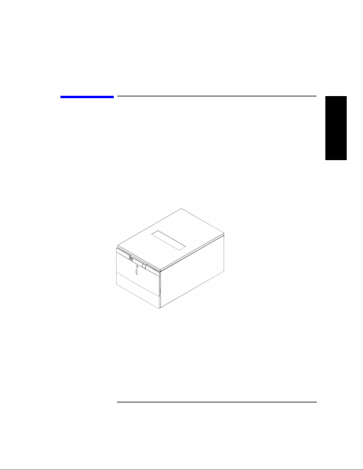
• Fully automated
• State-of-the-art patented HP robotics
• Industry-leading data ava ilability
• Industrial-strength durability
• User-maintenance-free library system
A vailable configurat io n s ar e d escribed in Tab le 1-1 on page 1-4.
Figure 1-1 HP DLT Tape Library
Product Description
HP DLT Tape Library
Product Description
1-3
Page 16
Product Description
Product Matrix
Product Matrix
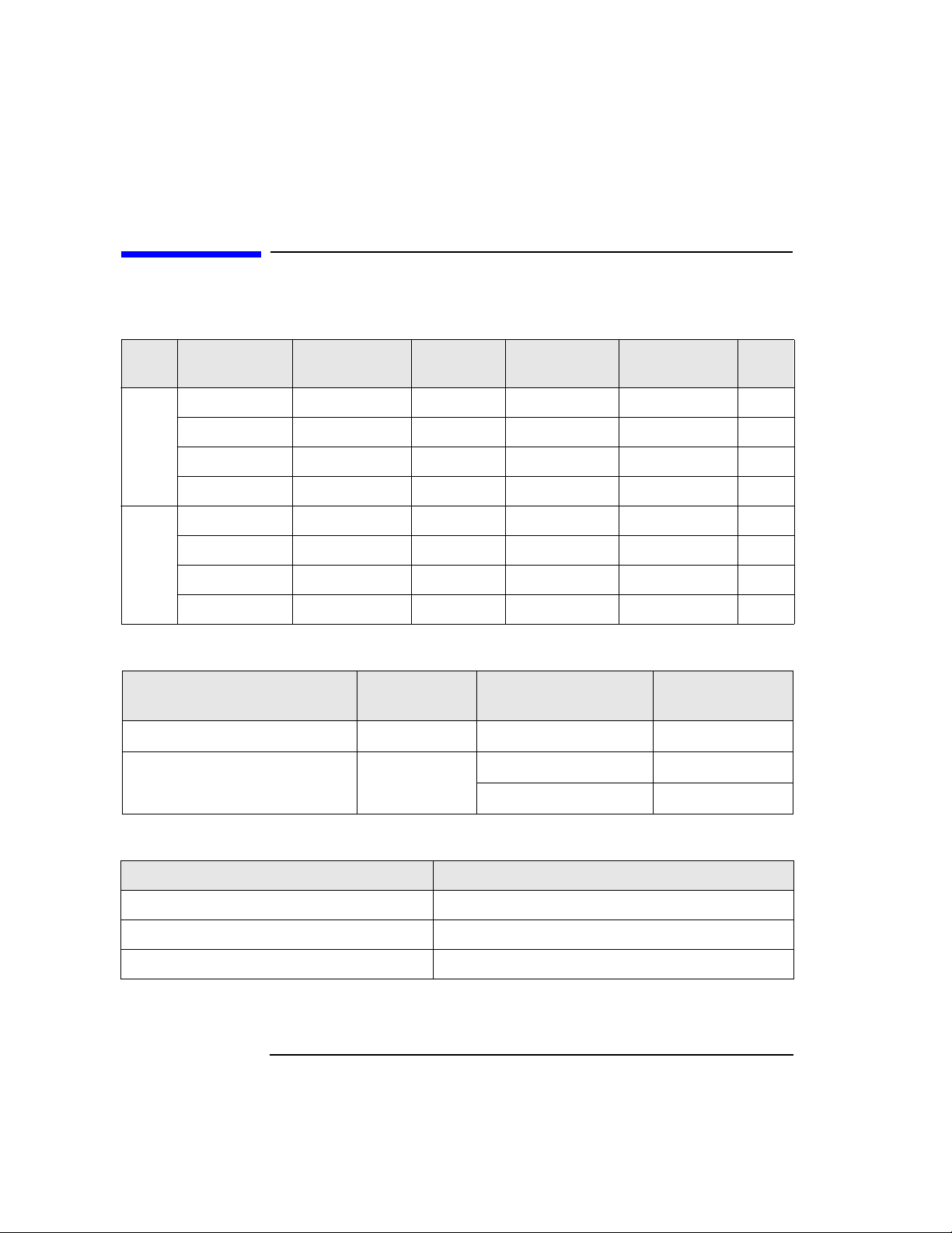
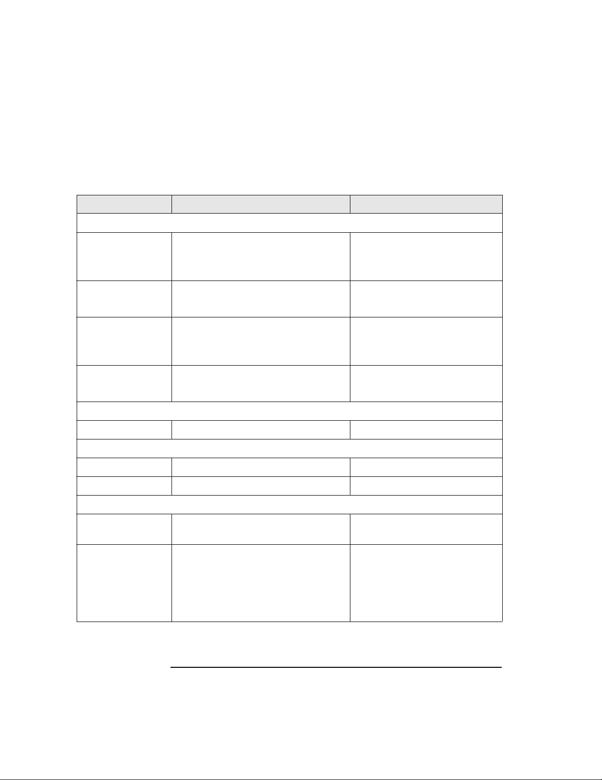
Table 1-1 DLT Tape Library Offerings
Library
Model
DLT4000 1/15 A4851A #A6K #401 One DLT4000 15
DLT4000 2/15 A4851A #A6K #402 Two DLT4000 15
Deskside
Field Rack
Table 1-2 Upgrade/C onver sion Kits
DLT4000 Upgrade Kit A4842A DLT4000 1/15 DLT4000 2/15
DLT 7000 Up grade/Conversion
Kit
DLT7000 1/15 A4851A #A6K #701 One DLT7000 15
Libraries
DLT7000 2/15 A4851A #A6K #702 Two DLT7000 15
DLT4000 1/15 A4851A #A6L #401 One DLT4000 15
DLT4000 2/15 A4851A #A6L #402 Two DLT4000 15
DLT7000 1/15 A4851A #A6L #701 One DLT7000 15
Libraries
DLT7000 2/15 A4851A #A6L #702 Two DLT7000 15
Kit
HP Product
Number
HP Product
Number
Mounting
Option
A4843A DLT4000 1/15 DLT7000 1/15
Config.
Option
Upgrades/Converts To
DLT7000 1/15 DLT7000 2/15
Drives Slots
Table 1 -3 DLT Tape Media
Media HP Product Number
HP DLTtape Type III XT C5141A
HP DLTtape Type IV C5141F
Cleaning Cartridge C5142A
1-4
Page 17

Supported Pl atforms
Table 1-4 DLT Tape Media
Product Description
Supported Platforms
Product Description
Servers
Workstation
On supporting platforms, the library can be connected to an HP Fibre
Channel SCSI multiplexer (HP A3308A and HP A3511A/Z) and thereby benefi t
from Fibre Channel speed and dis t an ce. The FC-SCSI multiplexer is
supported on K, T, and V platforms running HP-UX 10.20 TFC or higher.
(Consult an HP sales representative for the latest information.)
D-Class
E-Class
K-Class
Nova
T-Class
V-Class
J-Class
1-5
Page 18

Product Description
Library Rear Panel Features
Library Rear Panel Features
Figure 1-2 Rear Panel Features
6
1
5
5
1.
Bus 1 SCSI ports
robotics controller are internally connected to Bus 1.
2.
SCSI interface mode switches
differential settings for each SCSI bus.
3.
Bus 2 SCSI ports
connected to Bus 2 (two-drive library only)
4.
SCSI bus status indicator label
indicators.
5.
Power connector
6.
SCSI bus indicators
indicator.
4
(single-ended and differential). Drive 1 and the
specify term power, terminatio n and
(single-ended and di ffer ential). Drive 2 is inter nally
explains the SCSI bus status
connects the power cord to the library.
indicate SCSI bus status. Each SCSI bus has an
2
3
1-6
Page 19
Specificatio ns
Quantum DLT4000 and DLT7000 Drive
Mechanism Specifications
Product Description
Specificati ons
Table 1-5 DLT Drive Specifications
Characteristic DLT4000 DLT7000
Performance
Read/write transfer
rate:
maximum
sustained (DLTtape
Type I V)
Ave ra ge access time 68 seconds 60 seconds
Rewind 45 seconds (average)
Loading time to
BOT (for
previously written
tape)
Unloading time to
BOT
External Interface 8-bit SCSI-2, differential 16-bit fast/wide SCSI-2, differential
Internal Interface 8-bit SCSI-2, single-ended 16-bit fast/wide SCSI-2, single-ended
non-compressed mode:
1.5 MB/second
compressed (2:1 typical):
3.0 MB/second
90 seconds (maximum)
48 seconds (average) 48 seconds (average)
17 seconds (average) 17 seconds (average)
non-compressed mode:
5.2 MB/second
compressed (2:1 typical):
10.0 MB/second
60 seconds (average)
120 seconds (maximum)
Product Description
Read-write head 2-channel, ferrite w/MIG 4-channel, ferrite w/MIG
1-7
Page 20

Product Description
Specifications
Table 1-5 DLT Drive Specifications (Continued)
Characteristic DLT4000 DLT7000
Recording format 128 track serial serpentine variable
block (64 pairs)
208 track serpentine (52 quads)
416-tpi track density
256-tpi track density
Data compress
DLZ DLZ
algorithm
Reliability
Soft read error rate
Soft write error rate
Hard read error rate
Hard write
7
1 in 10
bytes minimum
(read as one error maximum
allowable in 10
7
of data read
minimum)
6
1 x 10
bytes minimum 1 x 106 bytes minimum
17
1 x 10
bytes minimum 1 x 1017 bytes minimum
Not allowed Not allowed
7
1 in 10
bytes minimum
(read as one error maximum
allowable in 10
minimum)
error rate
Undetected
1 x 10
30
bits read 1 x 1027 bits read
error rate
MTBF 80,000 hours 200,000 hours
Head life 10,000 hours 30,000 hours
7
of data read
Power Specifications
Total Power
consumption
22 W (average)
33 W (m a x i m u m)
5 volt supply 5.0 V +/- 5% (maximum)
@2.5 A (average) ,
3.0 A (maximum)
12 volt supply 12.0 V +/- 5%
@ 0.8 A (average),
1.5 A (maximum)
1-8
37 W (average)
47 W (maximum)
5.0 V +/- 5% (maximum)
@3.6 A (average),
3.8 A (maximum)
12.0 V +/- 5%
@ 1.6 A (average),
2.6 A (maximum)
Page 21
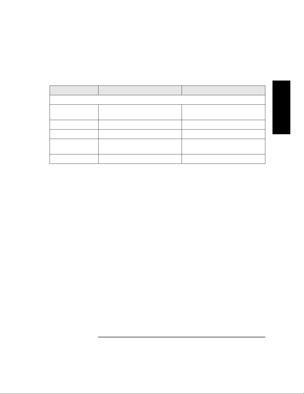
Table 1-5 DLT Drive Specifications (Continued)
Characteristic DLT4000 DLT7000
Physical Specifications
Product Description
Specificati ons
Product Description
Form factor 5 1/4 in. (height with modified
depth)
5 1/4 in. (height with modified
depth)
Height 3.25 in. (w/o bezel) 3.25 in. (w/o bezel)
Width 5.7 in. (behind bezel) 5.7 in. (behind bezel)
Depth 9 .0 in. (measured from back of front
bezel)
9.0 in. (measured from back of front
bezel)
We ight (net) 6 lb 7 oz 6 lb 7 oz
1-9
Page 22

Product Description
Specifications
DLT Tape Library Specifications
Table 1-6 Library Specifications
Characteristic A4851A Library
Performance
A verage tape
access
A verage tape
exchange
Interface SCSI-2 (single ended or differential)
MTBF 100,000 hours
MSBF (robotics) 1 million swaps
Preventive
maintenance
Total power
consumption
Line voltage 100 - 127/
Line frequency 50 to 60 Hz
Height 348 mm (13.7 in.) w/o bezel
<12 seconds
24 seconds (mean time to eject tape from drive, robotically exchange tape
from magazine and reload drive)
Reliability
None required
Power Requirements
140 W (typical) NOTE: After 30 minutes of non-operation,
150 W (maximum) the library operates in reduced power mode.
200 - 240 Vac
Physical Specifications
353.4 mm (13.9 in.) with bezel
Width 442 mm (17. 4 in .) w/o bezel
482.6 mm (19.0 in.) with bezel
Depth 717.3 mm (28.2 in.) w/o bezel
752.6 mm (29.6 in.) with bezel (t o tip of hand le)
Weight (net) 43.5 kg (96 lbs)
W e igh t (packaged) 49 kg (108 lbs)
1-10
Page 23

DLTtape Specificati ons
Table 1-7 Ta pe Specifications
Characteristic DLTtape Type III XT DLTtape Type IV
Product Description
Specificati ons
Product Description
Formatted capacity 15 GB
(non-compresse d)
30 GB
(2:1 typical compression)
20/35 GB
(non-compressed)
40/70 GB
(2:1 typical compression)
Basic description 0.5 in. (met al particle) 0.5 in. (metal pa rticle)
Tape length 1167 ft 1778 ft
Cartridge
4.1 in. x 4.1 in. x 1.0 in. 4.1 in. x 4.1 in. x 1.0 in.
dimensions
Shelf life
30 years (min) @ 20
40% RH
(non-condensing)
Usage 1,000,000 passes (min)
10,0 00 lo a d s/un lo a d s (mi n )
o
C
30 years (min) @ 20o C
40% RH
(non-condensing)
1,000,000 passes (min)
10,000 loads/unloads (min)
1-11
Page 24
Product Description
Specifications
Envir onmenta l Specific a t ions
Table 1-8 Environmental Specifications
Characteristic Tape/Drive DLT Tape Library
Temperature and Humidity
Operating 10° to 40° C
20% to 80% RH (drive, non-condensing)
40% to 60% RH (tape, non-condensing)
Non-operating
w/o disk
Storage/shi pmen t -40° to 66° C (drive)
Archive 18° to 28° C
Operating 0 to 30,000 ft N/A
Non-operating 0 to 50,000 ft N/A
Operating 60 half sine shock impulses of 5 g’s for
0° to 55° C
10% to 95% RH
16° to 32° C (tape)
10% to 95% RH
40% to 60% RH
Gradient
10° C/hour 15° C/hour
Altitude
Shock
11 sec in 3 axes
10° to 40° C
10% to 90% RH
-40° to 70° C
10% to 90% RH
-30° to 60° C
(<14 consecutive days)
-30° to 60° C
(<14 consecutive days)
4-in. half sine edge drop, 4faces
Non-operating half sine, 55 g, 11 ms
half sine, 140 g, 2 ms
half sine, 15 g, 20 ms
half sine, 150 g, 3 ms
half sine, 40 g, 11.8 ms
(all measured in 6 axes)
1-12
30 g
(trapezoidal wave, edge drop)
Page 25
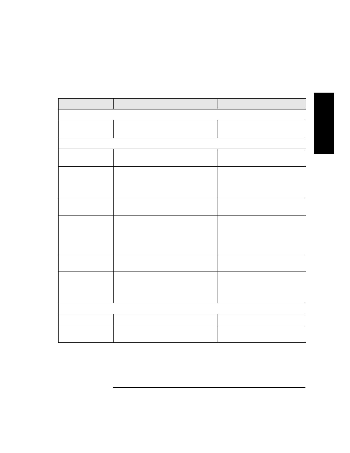
Table 1-8 Environmental Specifications (Cont i nued)
Characteristic Tape/Drive DLT Tape Libra ry
Package shock
Product Description
Specificati ons
Product Description
Drop tests 42 in. (packaged drive dropped on six
sides, three edges, one corner)
Vibration
Operating random 5 - 500 Hz @ 1 grms
10 minutes, 3 axes
Operating sine 0.25 g peak 10 - 300 Hz
0.1 g peak 300 - 500 Hz
10 - 500 - 10 Hz @ 1/4 octav e/m inute in 3
axes
Non-operating
random
Non-operating
swept- sine
5 - 500 Hz @ 2 grms
60 minutes, 6 axes
5 - 10 Hz @ 0.5 g peak
10 - 50 Hz @ 1 g peak
50 - 500 Hz @ 3 g peak
5 - 500 - 5 Hz @ 1/2
octave/minute in 6 axes
Non-operating
random packaged
Non-operating
swept si ne
packaged
2 - 200 Hz @ 1.5 grms
6 axes, dwell = 30 m
5 - 150 Hz @ 0.5 g peak
5 - 150 - 5 Hz @ 1/2 oct/min, 6 axes with
dwell at lowest natural resonance in
each axes
12-in. drop, 5 faces
0.21 grms
N/A
2.1 grms
0.5 grms (0 to peak)
1.49 grms, top-to-bottom
0.5 G (0-pk), 3 - 200 - 3 Hz 1
oct/min, 1 axis (top-to-bottom)
Acoustic Emission
Media exchange N/A 6.5 Bels
Read/write
4.3 Bels (max) A-weighted 6.5 Bels
operation
1-13
Page 26

Product Description
Specifications
DLT Tape Library P r oduct Certifications
Table 1-9 Product Certification
Safety EN60950/IEC 950
Electromagnetic emissions EN55022/CISPR - 22, Class B
EN50082 - 1
EN55024 - 2/IEC 1000 - 4 - 2, 4kV CD,
8kV AD
EN55024 - 3/IEC 1000 - 4 - 3, 3 V/m
EN55024 - 4/IEC 801 - 4,
1kV Peak Power lines
0.5 k V S ignal lines
FCC 47 CFR Part 15 - Cla ss B
VCCI Class B
EN61000 - 3 - 2/IEC 1000 - 3 - 2
EN61000 - 3 - 3/IEC 1000 - 3 - 3
Laser EN60825 (1994)/IEC 825 (1993)
+A1, Laser Class 1
1-14
Page 27

2 Library Installation
2-1
Page 28

Library Installation
Overview
Overview
To install the library:
1. Choose a location.
2. Prepare library components.
3. Install the host SCSI card(s).
4. Mount the library in a rack (rack mount configuration only).
5. Set the SCSI interface mode switch.
6. Con n ect th e libr ary to the host.
7. Con n ect power.
8. Con f igu r e th e hos t .
This chapter also explains how to move or ship the library.
NOTE Installation must be performed by HP qualified personnel.
2-2
Page 29

Step 1: Choose a Location
Choose a location that meets the following criteria. Take the library there
before unpacking it.
Table 2-1 Location Criteria
Library Installation
Step 1: Choose a Location
Room
temperature
Power source AC power voltage: 100-127 V or 200-240 V
Air quality Minimal sources of particulate contamination. Avoid
Adequate
clearance
50-104° F (10-40° C)
areas near frequently-used doors and walkways,
stacks of supplies that collect dust, and smoke-filled
rooms.
CAUTION: Excessive dust and debris can damage
tapes and tape drives.
Standalone configuration — free stand in g o r against a
wall/desk:
Back 56 cm (22 in.) for cooling and service.
Front 86 cm (34 in.) for operator access.
Sides56 cm (22 in.) for removal of the external cover.
Rack mount configuration:
Back Allow adequate room to open the rear
door of the rack for service access,
usually 46-61 cm (18-24 in.), depending
on the rack.
Library Installatio n
Front 86 cm (34 in.) for operator access.
Height For ease of use, the bottom of the lib rary
should be 60-120 cm (24-4 8 in.) above th e
floor .
2-3
Page 30

Library Installation
Step 2: Prepare Components
Step 2: Prepare Components
Make sure all required components are available.
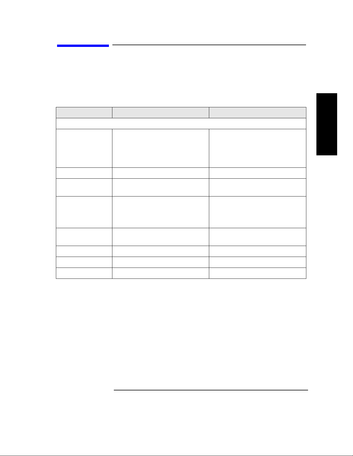
Table 2-2 Components Required for Installation and Use
Component Installation Notes
Library Do not unpack the library until it is in the
proper location.
SCSI card(s) Required number of cards installed in host depends on
library configuration. Connect drives and robotics
controller t o differential fast/wid e SCSI cards.
SCSI cables Required number of cables (68-pin) is one per drive and
one for the robotics controller. Maximum cable length
(total) is 25 meters.
Power cord P ower c ord is included wit h library.
Rack mount kit Rack mount kit is included with rack mount libraries.
Data cartridge One HP DLTtape IV data cartridge is incl u de d with
library.
Cleaning
cartridge
If any components are missing, contact a sales representative.
2-4
Cleaning cartridge is included with library.
Page 31

Library Installation
Step 3: Install the Host SCSI Card(s)
Step 3: Install the Host SCSI Card(s)
Refer to the host user manual and the SCSI card installation instructions for
information on installing SCSI cards.
Library Installatio n
2-5
Page 32

Library Installation
Step 4: Mount the Library in a Rack
Step 4: Mount the Library in a Rack
For rack mount configurations, refer to the ins t allation instructions included
in the rack mount kit.
2-6
Page 33

Step 5: Set the SCSI Interface Mode Switch
Do not connect any cables yet.
The SCSI interface mode switch, shown below, is on the rear panel between
the bus 1 and bus 2 SCSI ports.
Figure 2-1 SCSI Interfac e Mode Switch
To set the SCSI interface mo de switch:
1. Determine h ow to connect the library according to:
Library Installation
Step 5: Set the SCSI Interface Mode Switch
Library Installatio n
• Number of drives in the library and drive type (only DLT4000 drives
are supported as daisy-chained)
• Number of SCSI cards
2. Set the SCSI interf ace mode switch.
Table 2-3 SCSI Interface Mode Sw it ch Settings
Setting Purpose Set to
Term Pwr Sends power to the terminator ON in most installations
Termination Terminates the SCSI bus; functions
the same as a physical terminator
DIFF/SE Specifies interface mode DIFF for differential
ON if one port on the bus is open
OFF if both ports on the bus are
connected to a cable
2-7
Page 34

Library Installation
•bus 2 not
used
Step 5: Set the SCSI Interface Mode Switch
Table 2-4 shows three ways to connect the library and the corresponding
SCSI interface mode switch settings .
Table 2-4 Library Con nection Options
Configuration Cabling
One-Drive Library
Two-Drive Library
Daisy chained
(DL T4000 drives only)
Minimu m host
I/O slots used
SCSI Interface Mode Switch
Settings
Two-Drive Library
Bus 1 and bus 2
connect to separate
SCSI cards
Maximum performance
Additional card and
cable required
2-8
Page 35

Library Installation
Step 6: Connect Library to Host
Step 6: Connect Library to Host
1. Ensure the host system has been properly shut down and powered off.
2. Con n ect th e SCSI cables.
The SCSI bus configuration was de termined when the SCSI interface
mode switch was set (see the connect ion diagr am on page 2-8). Us ing this
configuration, connect the library to the host. Make sure:
• The differential port is used.
• The last device in the SCSI bus is terminated.
3. Make sure the power switch o n the li brar y fr o n t panel is switched off (0
position).
4. Plu g the power cord int o the power port on the back of the li b rary.
Stand-alone in stallations: Go to “Step 7: Connect Power” on page 2-13.
Library Installatio n
Rack mount installations: Go to the next section, ”Routing SCSI and Power
Cables on Rack Mounted Libraries.”
2-9
Page 36

Library Installation
Step 6: Connect Library to Host
Routing SCSI and Power Cables on Rack Mounted
Libraries
CAUTIO N SCSI and power cables must be routed and secured properly on rack
mounted libraries. Failure to properly route library cables could result in
damage to the cables.
To properly route and secure rack mounted library power and SCSI
cables:
1. Rou te the SCSI/power cables through the strain relief bracket:
a. Squeeze the two plas tic ends of the cable stra in relief bracket toget her.
b. Pull off the plastic strai n rel ief clamp.
c. R oute the SCSI cable(s) and the power cord through the cable strain
relief bracket.
d. Slide the strain r elief clamp back onto the bracket.
e. Attach a cable tie (included in the rack mount kit) to the SCSI and
power cables about eight inches back from the strain relief bracket.
f. Attach another cable tie abo ut eight inches back from the first cable
tie.
Figure 2-2 SCSI/Power Cables and Strain Relief Bracket
2-10
Page 37

Library Installation
Step 6: Connect Library to Host
2. Extend the rack’s antitip rail and verify that the leveller feet are down.
WARNING
Failure to extend the antitip rail could result in personal injury
and/or damage to the library if the rack tips over.
3. Use the key to open the front access door. Remove the tw o scre ws that
secure the library to the rack.
Figure 2-3 Front Ac cess Door
Library Installatio n
4. Slide the library out of the rack so that it is in the fully extendedposition.
5. Gently pull the SCSI and power cables back toward t he rear o f the rack .
Use a cable tie to secure them to the ra il at the back of the rack. T he cable
tie should be at about the same height as the top of the library.
2-11
Page 38

Library Installation
Step 6: Connect Library to Host
6. Carefully route the cables down along the back rail. Use a cable tie to
secure them to the rail just above the sli d e mounting bracket. Clip off the
ends of all four cable ties.
Figure 2-4 Secured SCSI and Power Cables
7. Close the back door on the rack.
8. Push the library back into the rack.
9. Open the front access door. Replace the two screws that secure the
library to the rack, then reloc k the door.
Figure 2-5 Front Ac cess Door
2-12
Page 39

Library Installation
Step 7: Connect Power
Step 7: Connect Power
1. Plug the power cord into a proper outlet.
2. Turn on the power switch.
SELF TEST and NOT READY, and then NOT READY and INVENTORY
CHECK display alternately. After the power-on test completes (in about 3
minutes), the drive status information displays. (See “Understanding the
Display Window” on page 4-4.)
NOTE If the drive status information does not display, the power-on test was not
successful and DEVICE FAILED displays. See “resolving Other Problems”
on page 4-43.
3. Turn on the host system.
Library Installatio n
2-13
Page 40

Library Installation
Step 8: Configure the Host
Step 8: Configure the Host
An HP qualified service representative must configure the library on the host.
This procedure includes installing drives, creating device files and verifying
the configuration.
2-14
Page 41

Library Installation
Moving or Shipping the Library
Moving or Shipping the Library
This section explains how to move the library a short distance, such as to
another office or to another floor in the building, and how to ship the library
to another location.
WARNING
CAUTION Do not switch off power to the library until the SCSI bus is inactive.
The library weighs nearly 100 pounds (45 kilograms). To avoid
personal injury and possible damage to the library, at least two
people must move the library.
To move or ship the library:
1. Properly shut down and power off the host.
2. Unmount (unreserve) any tape cartridges in the library if necessary. See
your computer operating system documentation, or software application
documentation for instructions on how to unmount tape cartridges.
3. Verify that all drives in the library are empty:
displays after the drive number if the drive is empty.
displays after the drive number if the drive is full.
If the drives are full, empty them before shipp ing th e library. (For
instructions, refer to the software documentation your host system uses
to manage the library.)
4. Switch off the power switch on the library front panel.
Removing power from a SCSI peripheral when the bus is active can result in
data loss and/or indeterminate bus states. (Check your host system manuals
for information about checking the SCSI bus status.) If your computer is
connected to a LAN, be sure to check with your system administrator before
shutting off power to the library.
Library Installatio n
5. Remove the power cord and the SCSI cable connections from the library
rear panel.
2-15
Page 42

Library Installation
Moving or Shipping the Library
6. If the library is rack mounted:
a. Extend the antitip rail on the rack.
WARNI NG
Failure to extend the antitip rail could result in personal injury
and/or damage to the library if the rack tips over.
b. Slide the library out of the rack so that it is in the full y ex ten d ed
position.
c. Reattach the handles to the side of library using two screws. Make
sure the handle flanges are on top of the slides. (The handles and
hardware for reattaching them should have been saved with the
original shi p pi n g materials. If they are missing, call your service
representativ e for assistance in getting replacemen t handles.)
d. Remove the three 8-32 screws on each side of the library that secure
the library to the rack slides.
7. IMPORTANT — two people needed: With a person on each side of the
library, lift the library onto a cart.
8. Transpo rt th e lib rar y:
• To move the library a short distance, roll the cart to the new location.
• To ship the library, repackage the library in the same materials and
ship it in the same manner in which it was received, then unpack it at
its new destination.
CAUTION The library can be seriou sly damaged if it is not shipped usin g appro p riate
shipping mater ials. A service representative can p rovide assistan ce o r advice
on how to best repackage and ship the library.
9. Re-install the librar y. Refer to install ation st eps 3 through 8 in th is chapte r.
2-16
Page 43

3 Tape Cartridges
3-1
Page 44

Tape Cartridges
Overview
Overview
• Choosing Tape Cartridges
• Labeling Tape Cartridges
• Write-Protecting Tape Cartridges
• Maintaining Tape Cartridges
• Labeling Bulk Load Magazines
3-2
Page 45

Tape Cartridges
Choosing Tape Cartridges
Choosing Tape Cartridges
Two tape cartridges are supported.
Table 3-1 Supported Tape Types
Cartridge Type Available Densities
DLTt ap e IV Data Cartridge 20 GBytes (DLT 4000 drive)
35 GBytes (DLT7000 drive)
DLTtape III XT Data Cartridge 15 GBytes
NOTE Hewlett-Packard rec ommends using the HP DLTtape IV Data Cartridge. (See
Appendix A for ordering information.)
Tape Cartridges
3-3
Page 46

Tape Cartridges
Labeling Tape Cartridges
Labeling Tape Cartridges
Make it a practice to use bar code labels on your tape cartridges. Your host
software may need to keep track of the following information and the
associated bar code:
• date of format or initialization
• cartridge owner (such as group or department)
• storage purpose (such as backup, old version of operating system)
If the host software does not keep track of this information, create a method
of doing so.
Slide the label into th e slot o n the fac e of the car tridge as illustrated in
Figure 3-1.
NOTE If bar code labels are not used and the Barcode On/Off configuration is set to
On, the Inventory Check test perfor mance can b e significantly affected. Thi s
test runs when the library is powered on an d w he ne ver the front access door
is used.
Figure 3-1 Proper Label Positio n
3-4
Page 47

Tape Cartridges
Write-Protecting Tape Cartridges
Write-Protecting Tape Cartridges
The use of the write protect switch ensur es data safety for files that have
been previously wri tten t o the tape and prevents any additional files from
being written to the tape.
To change the write-protect setting,
• Left to
prevent
data from being written to the cartridge. The orange
indicator on the cartridge can be seen when the write-protect switch is in
the “ON” position (see “A” in Figure 3-2).
•Right to
data to be written to the cartr idge. The or ange i ndicator on
allow
the cartridge cannot be seen when the write-protect switch is in the
“OFF” position (see “B” in Figure 3-2).
With the write-protect switch in either position, data can be read from the
cartridge.
Figure 3-2 Write-Protect Button Set tings
Write-Protected
move the write-protect switch:
Tape Cartridges
Not Write-Protected
3-5
Page 48

Tape Cartridges
Maintaining Tape Cartridges
Maintaining Tape Cartridges
Table 3-2 Ta pe Cartridge Maintenance
DO NOT: DO:
• Expose cartridges to magnetic fields.
• Leave cartridges in the tape drive when library
power is off.
• Expose cartridges to extreme temperatures or
extreme humidity. Acceptable operating
temperatures range from 10- 40° C (50-104° F).
Acceptable storage temperatures range from
16-32° C (60-90° F). Accep table operatin g h u midity
ranges from 20-80%; acceptable storage humidity
ranges from 10-95%.
• Expose cartridges to moisture or direct sunlight.
• Dro p the cartridges or carry them in a loose
container that could submit the cartr id ges to any
unnecessary physical shock.
• Open cartridges lid, exposing the tape to possible
contamination or physical damage.
• Touch the tape surface.
• Take cartridges apart.
• Use graphite pencils, water soluble felt pens, or
other debris-producing writing instruments to
label cartridges.
• Store cartridges in a clean, safe
place in their protective plastic
containers when not in use.
• Remove dust on the outside of
cartridges using a damp cloth.
(Older, frequently used tapes may
build up dust.)
• Store cartridges vertically, not flat.
• Store cartridges intended for
archiving data in th eir plastic
containers and in environmental
conditions of 18-28° C (64-82° F)
and 40-60% relati ve h umidity.
• Use labels like th ose include d in the
accessories kit or that meet the
specifications listed in Appendix A,
“Supplies and Accessories”
• Erase a label; replace it instead.
3-6
Page 49

Labeling Bulk Load Magazines
Bulk load magazines can b e labeled in a manner similar to tape cartr id ges.
To label bulk load magazines:
1. Clean the magazine surface with isopropyl alcohol (optional, but
recommended).
2. Remove the adhesive backing from the label pouch.
3. Apply the pouch to the magazine.
4. Slide the label into the pouch.
Figure 3-3 M agaz ine Label Position
Tape Cartridges
Labeling Bulk Load Magazines
Tape Cartridges
3-7
Page 50

Tape Cartridges
Labeling Bulk Load Magazines
3-8
Page 51

4 Library Oper ation
4-1
Page 52

Library Operation
Overview
Overview
• Operating the Control Panel
• Understanding the Display Window
• Entering the Administration Menu Password
• Setting a New Administration Menu Password
• Specifying SCSI Addresses
• Setting Configuration Options
• Retrieving Performan ce In fo rmatio n
• Running an Internal Test
• Using Online Repair
• Loading Cartridges Into the Library
• R emoving Tape Cartridges from the Library
• C leaning the Tape Drives
• C learing a Drive Cleaning Error
• Viewing Cartridge Bar Code Labels
• Troubleshooting
4-2
Page 53

Operating the Control Panel
Figure 4-1 Tape Library Control Panel
1.
Selection buttons
•
•
CANCEL
PREV
cancels the current operation or option.
scrolls the display options backward by one. When held
continuously, the options scroll quickly.
NEXT
•
scrolls the display options forward by one. When held
continuously, the options scroll quickly.
ENTER
•
2.
Activity light
selects the displayed option.
• Steady Green – power is on.
• Flashing Green – a tape cartridge is be in g accessed.
• Amber – fault indicator.
3.
16-Character Display
or drive status.
An asterisk (*) indicates there is a menu beneath the option. Press
to access the menu. Press
4.
Power switch
5.
Door latch
locks/unloc ks door for access to bulk load magazines.
perform the following operations:
indicates the following:
displays information about the current operation
switches power to the unit on and off.
NEXT
or
Operating the Control Panel
PREV
to display the menu options.
Library Operation
ENTER
Library Operation
4-3
Page 54

Library Operation
Understanding the Display Window
Understanding the Display Window
The display window displays drive status indicators and menu options.
Drive Status
Drive status displays when the library is in the “read y” state. For example:
Drive number
Status indicator
Activity indicat or
1 2
In this example:
• Drive 1 has a cartridge inserted and data is being written to the tape.
• Drive 2 has a write-protected cartridge inserted.
P
The library has one or two drives,
depending on the model number.
Status Indic ators
The drive is full.
The drive is empty.
The drive needs to be cleaned .
C
The tape cartridge in th e drive is write-protect ed .
P
Blank – The drive is offline.
Activity Indicat or s
The activity light flashes during the following operations:
Information is being written to the tape in the drive.
Information is bein g read from the tape in the drive.
The tape in the drive is being searched backward or is rewinding.
The tape in the drive is being searched forward.
C
The drive is being cleaned.
4-4
Page 55

Contro l Panel Opt ions
Library Operation
Understanding the Display Window
Press
PREV
or
NEXT
while the library is in the “ready” state to display first
level options. Access second level options from ADMIN* (second level
options require a password; see “Entering the Administration Menu
Password” on page 4-7).
An asterisk (*) indicates that the option has multiple selections.
or
ENTER
to select the option or display
NEXT
to display other available options.
When a menu selection is flashing, press
the option’s selections. Press
PREV
First Level Options
RELEASE DOOR Allows the rear access door to be unlocked.
VIEW BAR
CODES*
Displays the bar code labels on each tape cartridge
by slot number.
ADMIN* Accesses second-level options.
Second Level Options
INFO* Displays performance information stored in the
library.
TEST* Runs internal library tests.
Library Operation
CONFIG* Customizes the way the library functions.
CLEAN DRIVES* Displays the drive numbers to clean.
OVERRIDE DOOR* Opens door when media is in drives.
SCSI IDs* Sets the SCSI addresses for the robotics and the
library drives.
ONLINE REPAIR* De-ac t ivates a drive for replacement.
4-5
Page 56

Library Operation
Understanding the Display Window
Control Panel Menu Tree
Figur e 4-2 Control Panel Menu Options
PREV/NEXT
1 2 ADMIN *
Drive Status Indicators
C
drive needs to be cleaned
tape is write-protected
P
drive is empty
drive is full
(blank) drive is offline
drive is being cleaned
C
↓
drive is writing to tape
drive is reading from tape
searching tape forward
<<
searching tape backward
TEST *
RELEASE DOOR
If the drive(s) are not empty:
ENTER
EMPTY DRIVES NO
PREV/NEXT
EMPTY DRIVES YES
PREV/NEXT
VIEW BAR CODES
###### S LOT 1
###### SLOT 15
PREV/NEXT
CLEAN DRIVES *
ENTER
PREV/NEXT
PREV/NEXT
PSWD 00 0 000 000
(See “Changing the
Administration Password.”)
SCSI IDs *
ENTER
ENTER
INFO * CONFIG *
ENTERENTER ENTER
REVISION
LIB ODOMETERS *
HOURS
MOVES
XLATES
DRIVE LOADS *
DRIVE 1
DRIVE 2
DRIVE FW *
D1 REVISION #
D2 REVISION #
INTERFACE FW *
BUS NUM = #
FAST/WIDE SCSI
8052 REV #
8052 CKSUM #
COBRA REV #
HARD ERRORS *
HARDWARE ERR #
FRU 1-3 #
MOTION <name>
SOURCE #
DESTINATION 1 #
DESTINATION 2 #
ODOMETER #
MICROMOVE 1-6 #
MICROMOVE ER #
SOFT ERRORS *
(same logs available
as under "HARD
ERRORS")
RECOVERY ERRORS *
(same logs available
as under "HARD
ERRORS")
EXERCISE MECH
EXCHANGE DEMO
IO DRI VE
IO MAGAZINE
INVENTORY CHECK
TEST TRANSLATE
TEST VERTICAL
WELLNESS TEST
FIND PLUNGE HOME
FIND VERT HOME
FIND XLATE HOME
INIT MECHANICS
EMPTY DRIVES
EMPTY PICKER
FILL PICKER
REWIND MEDIA
CLEAR SOFT LOG
CLEAR HARD LOG
PLUNGE FULL SPD
PLUNGE 1/2 SPD
SENSOR TRANSLATE
SENSORS MAGAZINE
SENSORS ST ARWARS
VERTICAL ENCODER
ONLINE REPAIR*
ENTER ENTER
DRIVE POWER *
DRV1 PO WER ON/OFF
DRV2 POWER ON/OFF
DRIVE STATUS *
DRV1 ON/ GOOD
OFF/FAILED
DRV2 ON/GOOD
OFF/FAILED
RECOVERY ON/OFF
RESTORE DEFA ULTS
CLEAR ODOMETERS
STARWARS ON/OFF
NEW PASSWORD
SCSI LOG ON/OFF
SECURE ON/ OFF
POWER SECURE
ON/OFF
REP RECO V ERED
ON/OFF
CONF40 ON/OFF
BARCODE ON/OFF
OVERRIDE DOOR *
ENTER
SEL CLEAN CART *
###### SLOT #
or
CLN CART LOC #
CLEAN DRIVE 1
CLEAN DRIVE 2
CLEAN DRIVE ALL
SET IDs *
LIB ID #
DRIVE 1 ID #
DRIVE 2 ID #
UPDATE IDs NOW
VIEW IDs *
LIB ID #
DRIVE 1 ID #
DRIVE 2 ID #
• An asteris k (*) ind icates there are menu choices
below the displayed option.
•Press
•Press
•Press
PREV
ENTER
CANCEL
NEXT
or
to scroll through the menus or options.
to select a menu or option.
to go “up” a level on the menu tree.
4-6
Page 57

Library Operation
Entering the Administration Menu Password
Enterin g the Ad ministration Menu
Password
1 2 ➔ ADMIN* ➔ PSWD 000-000-000 ➔ CONFIG*
A numeric password is required to access options beneath ADMIN* menu of
the library (see Figure 4-2 on page 4- 6). A three-part password of 000-000-000
is set at the factory. To allow only authorized persons to access the library
and change operation settings, the password must be changed.
NOTE To change the password, s ee “Setting a New Administration Menu Password ”
on page 4-8.
Do not forget the password. Only an HP qualified service representative can
reset the security code to the factory setting.
To enter the password:
1. Verify that the drive status displays (if not, press
2. Press
NEXT
until ADMIN* displays, then pres s
ENTER
CANCEL
until it does).
.
3. PSWD 000-000-000 displays, and the first set of zeros flashes.
ENTER
Press
NEXT
or
to accept this number (if no password has been set), or pres s
PREV
until the set number displays. Press
ENTER
.
4. The middle set of zeros flashes.
ENTER
Press
NEXT
or
to accept this number (if no password has been set), or pres s
PREV
until the set number displays. Press
ENTER
.
5. The last set of zeros flashes.
ENTER
Press
NEXT
or
To access options under the ADMIN* menu, press
desired option displays, then press
to accept this number (if no password has been set), or pres s
PREV
until the set number displays. Press
ENTER
.
PREV
ENTER
. INFO* displays.
NEXT
or
until the
Library Operation
4-7
Page 58

Library Operation
Setting a New Administration Menu Password
Setting a New Administration Menu
Password
1 2 ➞ ADMIN* ➞ PSWD 000 000 000 ➞ CONFIG* ➞ NEW PASSWORD
NOTE Do not forget the password. Only an HP qualified service representative can
reset the security code to the factory setting.
To set a new password:
1. Follow the steps on the previous page to enter the existing or factory -set
password.
NEXT
NEXT
NEXT
ENTER
until
or
or
2. Press
3. Press
NEW 000-000-000
4.
Press
press
PREV
PREV
.
CONFIG*
until
displays, then press
NEW PASSWORD
displays, and the first set of zeros flashes.
to display the desired first part of the password, then
ENTER
.
displays, then press
ENTER
.
5. The second set of zeros flashes.
NEXT
Press
then press
PREV
or
ENTER
to display the desired second part of the password,
.
6. The last set of zeros flashes.
NEXT
Press
ENTER
press
PASSWORD CHANGED
7.
or
.
PREV
to display the desired third part of the password, then
displays. Press
CANCEL
three times to return to the
drive status (“ready” state).
NOTE Save the new password to flash ROM by power cycling the library (turning
the library off and then on). This allows the password to be recovered if the
library is powered off for more than ten days.
4-8
Page 59

Library Operation
Specifying SCSI Addre sses
Specifying SCSI Addresses
1 2 ➞ ADMIN* ➞ PSWD 00 000 000 ➞ SCSI IDs
NOTE The tape library has a Fast/Wide SCSI interface. SCSI addresses can be set
from:
• 0 to 7 on a DLT4000-based library
• 0 to 15 on a DLT7000-based library
If connecting to a narrow host, use only addr esses 0 to 7.
Table 4-1 SCSI ID Options
Option Purpose Explained in
SET IDs* Assigns individual SCSI IDs to each
drive and the robotics contr o ller .
VIEW IDs* Displays the current drive and robotics
controller settin gs.
Table 4-2 Default SCSI Address Settings
DEVICE SCSI ID BUS #
LIB 6 Bus 1
DRV 1 5 Bus 1
DRV 2 (two-drive models only) 4 Bus 2
“Setting SCSI Addresses” on
page 4-10
Library Operation
Viewing Current SCSI Addresses”
on page 4-10
4-9
Page 60

Library Operation
Specifying SCSI Addresses
Viewing Current SCSI Address Settings
1 2 ➞ ADMIN* ➞ PSWD 000 000 000 ➞ SCSI IDs ➞ VIEW IDs
To view the current SCSI address settings:
a. Verify that the drive stat us displ ays (if not, press
NEXT
b. Press
until ADMIN* displays, then press
CANCEL
ENTER
until it does).
.
c. Enter the three-part numerical passwor d (see “E ntering the
Administration Menu Password” on page 4-7).
NEXT
d. Press
until SCSI IDs* displays, then press
8. SET IDs* displays. Press
ENTER
.
NEXT
until VIEW IDs* displays, then press
ENTER
.
9. BUS1 LIB ID# or BUS# DRV * ID * displays. (BUS1 LIB ID # stands
for the current SCSI ID of the robotics controller.
BUS# DRV # ID # is the current SCSI ID setting for the displayed dri ve
number and its associated BUS#.)
Press
a. Press
NEXT
CANCEL
PREV
or
to scroll through the current address settings.
until the next operation to perform displays, or until the
drive status (library “ready” state) displays.
Sett i ng SCSI Addr esses
1 2 ➞ ADMIN* ➞ PSWD 000 000 000 ➞ SCSI IDs ➞ SET IDs
A SCSI address is required for the robotics controller and each drive. For
more information, see Table 4-2, “Default SCSI Address Setting” on page 4-9,
and the section “Vi ewi ng Current SCSI Addresses” on page 4-10.
When setting SCSI addresses, note that:
• On bus 1, drive 1 uses one address and the robotics controller uses one
address.
• On bus 2, drive 2 uses one address (two-drive libraries only). If the drives
are daisy-chained, the robotics and each drive use one addres s on the bus.
To change the current SCSI address setting s:
1. Verify that the drive status displays (if not, press
2. Press
NEXT
until ADMIN* displays, then pres s
ENTER
CANCEL
until it does).
.
4-10
Page 61

Specifying SCSI Addre sses
3. Enter the three-part numerical password (see “Entering the
Administration Menu Password” on page 4-7).
Library Operation
NEXT
4. Press
until SCSI IDs* displays, then press
5. SET IDs* displays. Press
ENTER
.
ENTER
.
LIB BUS1 ID # or DRV# BUS# ID # displays. (LIB BUS1 ID # stands
for the current SCSI ID of the robotics controller .
DRV# BUS# ID # is the current SCSI ID setting for the drive number and
its associated bus #.)
6. Press
NEXT
until the setting to change displays, then press
7. The current SCSI address setting flashes. Press
desired address displays, th en pres s
NEXT
8. Press
until UPDATE IDs NOW displays, then press
ENTER
.
NEXT
or
ENTER
PREV
ENTER
.
until the
.
9. WAIT FOR UPDATE displays briefly, then IDs SAVED displays.
• If the new settings do not conflict with other SCSI IDs on the bus,
SCSI IDs* displays.
• If the new settings conflict with other IDs on the SCSI bus, CONFLICT
ABORTED displays briefly, then SET IDs* displays. Any changes
entered are lost, and previous steps must be repeated to set a new
address.
• If any buses are daisy chained together, make sure the SCSI IDs are
different for each devic e on the bus.
• If a serial communications error is detected while trying to set the
SCSI IDs, DRV CONNECT ERR displays, followed by IDs NOT
CHANGED. Any changes entered ar e lo st. The SCSI IDs* menu
displays.
Library Operation
10. Press
CANCEL
three times to return to the drive status (“ready” state) .
11. To save new settings can be saved to flash ROM, turn the library off, then
turn it back on. This allows the settin gs to be recovered if the library is
powered off for more than ten days.
NOTE After changing an address, it may be necessary to reboot the host for the new
SCSI IDs to be recognized.
4-11
Page 62

Library Operation
Specifying SCSI Addresses
Interpreting SCSI Bus Status Indicator LEDs
Each SCSI bus has an LED to indicate the bus status.
Table 4-3 SCSI Status Indicators
Indication Status
Steady green Port active and OK. Internal (on-board) termination
enabled.
Flashing green Port active and OK. Internal (on-b o ard) termination
disabled.
No light Port not active or not configured.
Flashing red Bus mismatch or loss of external termination power.
Flashing yellow Bus offline for online drive replacement.
4-12
Page 63

Library Operation
Loading Cartridges Into the Library
Loading Cartridges Into the Library
Inserting/Removing Cartridges with Software
If the software package requires that cartridges be inserted and removed
using the software, check the softw are documentation before proceeding .
Label all cartridges before inserting them into the magazines. (See “Labeling
Tap e Cartridges” on page 3-4.)
The bar codes and storage slo t lo cations are stored in library me morywhen
the door is closed and the Inventory Check test is automatically run.
Keeping Cartridges in the Magazine
To prevent cartridges from slid in g o ut of the bulk load magazines when
inserting them into the library:
• DO NOT use excessive force when insertin g th e magaz in es. This can
cause the magazine “latching” mechanisms to fail.
Library Operation
• DO NOT insert magazines when the library power is turned off. During
normal library operation, the cartridge release button on top of the
magazine is pushed down by a special mechanism inside the library. This
“unlocks” the cartridges, allowing them to be inserted and removed from
the storage slots as needed. When the control panel RELEASE DOOR
option is enabled, the button on top of the magazine is released, which
“relocks” the cartridges into the magazine slots. During a power failure,
however, this button is not released, and cartridges can slide out of their
storage slots if a magazine is inserted or removed from the library. (If no
magazines are in a library, the special mechanism defaults to the position
that keeps cartridges locked into the magazine storage slot.)
4-13
Page 64

Library Operation
Loading Cartridges Into the Library
Loadin g Tapes
Tapes are bulk loaded into magazines, which are then inserted into the
library through the front access door. The library holds from one to three
5-slot magazines.
To load tapes:
1. Verify that the drive status displays (if not, press
CANCEL
until it does).
2. Verify that all drives in the library are empty (see the n ote below).
displays after the drive number if the drive is empty.
displays after the drive number if the drive is full.
3. Press
4. Press
NEXT
ENTER
PREV
or
until RELEASE DOOR displays .
. DOOR RELEASED displays. (See the note below. If an error
message displays, see “Resolving Other Problems” on page 4-43.)
NOTE The drive(s) must be empty before the access door can be released. If the
drive(s) are not empty, EMPTY DRIVES NO displays. Pre s s
until EMPTY DRIVES YES displays, then press
ENTER
.
NEXT
or
PREV
NOTE Some security configurations may prevent the access door from being
released. If a security option is enabled, SECURITY ENABLED displays after
the RELEASE DOOR option is chosen.
In some situations it may be necessary to override a security option and open
the access door . To open the acces s door when a secur ity option p revents the
door from being released, use the OVERRIDE DOOR option under the
ADMIN* menu (see Figure 4-2 on page 4-6) .
5. Unlock the access door using the key.
4-14
Page 65

Loading Cartridges Into the Library
6. Open the access door by pulling the top of the door outward.
NOTE Do not let the door fall open. The door straps may be damaged.
Figure 4-3 Opening the Front Acc ess D oor
7. Insert up to five tape cartridges into a magazine so that the tape brand
name printed on the top of the cartridge is facing up and the tape label is
facing out. The tapes should “click” into place.
Library Operation
Library Operation
Figure 4-4 Loading Tape Cartridges into the Magazine
4-15
Page 66

Library Operation
Loading Cartridges Into the Library
8. Insert the magazine so it lines up with the arrow on the label inside the
library, the handle is facin g the front of the library , and the tapes are
facing the inside of the tape library. The magazine should “click” into
place.
Figure 4-5 Inserting Magazines
9. Shut and lock the access door using the key lock. Make sure the door is
shut completely.
NOTE The library Inventory Check test runs when the access door is closed so that
an inventory of tape bar code labels and storage slot locations can be stored
into library memory. This process takes about one minute. The test fails if the
door is not completely shut.
WARNING
Do not attempt to disable the interlocks. If the library is operating
with fewer than thr ee magazin es inserted a nd the door open , the user
can be exposed to Class II laser light emitted from the bar code
reader.
4-16
Page 67

Library Operation
Removing Tape Cartridges from the Library
Removing Tape Cartridges from the Library
Some software package s re qu ire that tape cartridges be inserted and
removed using the software. If a softwar e pac ka ge manages files in the
library, check the software documentation before proceeding.
All drives must be empty before the access door can be rele ased. In additi on,
some security configurations may prevent the access door from being
released. If a security option is enabled, SECURITY ENABLED displays after
the RELEASE DOOR option is chosen.
To remove magazines from the library:
1. Verify that the drive status displays (if not, press
CANCEL
until it does).
2. Verify that all drives in the library are empty;
displays after the drive number if the drive is empty
displays after the drive number if the drive is full
3. Press
4. Press
NEXT
ENTER
PREV
or
until RELEASE DOOR displays .
. DOOR RELEASED displays. (See the following note. If an
error message displa ys, see “ Resolving Other Problems” on page 4-43.)
NOTE The drive(s) must be empty before the access door can be released. If the
drive(s) are not empty, EMPTY DRIVE NO displays. Press
EMPTY DRIVE YES display, then press
ENTER
.
NEXT
or
PREV
until
Some security configurations may prevent the access door from being
released. If a security option is enabled, SECURITY ENABLED displays after
the RELEASE DOOR option is chosen.
In some situations it may be necessary to override a security option and open
the access door . To open the acces s door when a secur ity option p revents the
door from being released, use the OVERRIDE DOOR option under the ADMIN*
menu (see Figure 4-2 on page 4-6).
Library Operation
4-17
Page 68

Library Operation
Removing Tape Cartridges from the Library
5. Unlock the access door using the key, then open the door.
NOTE Do not let the door fall open. Damage to the door straps may occur.
Figure 4-6 Opening the Front Acc ess D oor
6. Remove the desired magazine by pushing the button at the top of the
magazine handle (see Figure 4-7) and pulling out the magazine.
Figure 4-7 Removing Ma gazines
7. If necessary, remove tapes from the magazine. Press the button on top of
the magazine, then pull out the tape.
4-18
Page 69

Library Operation
Removing Tape Cartridges from the Library
WARNING
Do not attempt to disable the interlocks. If the library is operating
with fewer than thr ee magazin es inserted a nd the door open , the user
can be exposed to Class II laser light emitted from the bar code
reader.
8. Shut and lock the access door using the key lock. Make sure the door is
shut completely.
NOTE The library Inventory Check test runs when the access door is completely
closed so that an inventory of tape bar code labels and storage slot locations
can be stored into library memory. This process takes about one minute.
Library Operation
4-19
Page 70

Library Operation
Viewing Cartridge Bar Code Labels
Viewing Cartridge Bar Code Labels
Bar code label information can be viewed for each tape cartridge in the
library us in g the control panel. Bar co d e information displays sequentially by
storage slot number.
To view bar code information:
1. Verify that the drive status displays (if not, press
NEXT
2. Press
until VIEW BAR CODES* displays, then press
CANCEL
until it does).
ENTER
.
###### SLOT # displays. (“######” represents the bar code
information, and “#” represents the first storage slot that contain s a bar
coded tape cartridge.)
NOTE If there are no bar coded tape cartridges in the lib r ary , LIBRARY EMPTY
displays briefly, then VIEW BAR CODES* displays. Press
CANCEL
to return to
the drive status indic ato r s (“read y” state).
3. Press
NEXT
or
PREV
to scroll through the storage slot locations that
contain bar coded tape cartridges.
4. Press
CANCEL
twice to re tu rn to the drive st atu s indicators ( “read y” state).
4-20
Page 71

Cleaning the Tape Drives
1 2 ➞ ADMIN* ➞ PSWD 000 000 000 ➞ CLEAN DRIVES*
Cleaning the drives , which tak es about 5 minutes per drive, requ ires a special
digital linear tape cleaning cartridge. (T yp ically, cleaning cartridges are light
yellow and data cartridges are black, brown, or white . See Ap pe ndix A for a
list of supplies.)
The drive mechanisms do not require scheduled cleanings and should be
cleaned only if a “clean drive” status indicator ( ) displays after the drive
number.
If the cleaning car tridge needs to be r eplaced, REPLACE CLEANING di spl ays,
and the cleaning cartrid ge ejects through the mailslot.
NOTE The software package may manage drive cleaning.
C
Library Operation
Cleaning the Tape Drives
To clean one or more of the dr ives:
1. Verify that the drive status displays (if not, press
CANCEL
until it does).
2. Make sure all drives are empty ( displays after the drive number). To
empty the drives, refer to the documentation for the software package.
3. Press
NEXT
until ADMIN* displays, then pres s
ENTER
.
4. Enter the three-part numerical password (see “Entering the
Administration Menu Password” on page 4-7).
NEXT
5. INFO* displays. Press
ENTER
.
until CLEAN DRIVES* displays, then press
• If the library power has been turned off or the access door has been
opened since a cleaning car tridge location was las t selected, SET
CLEAN CART* displays. Pre ss
ENTER
.
• If the library power h as not been turned off or the access door has no t
been opened since a cl eaning c artridge loca tion was last s elected, CLN
CART LOC # displays (the number of the cleaning cartridge storage
slot last selected is flashing.) If the storage slot location is correct,
ENTER
press
. To select a different storage slot lo cation, press
until the correct st orage slot location displays, the press
ENTER
NEXT
.
Library Operation
4-21
Page 72

Library Operation
Cleaning the Tape Drives
###### SLOT # displays (“##### #” is a barcode number or is blank if
barcodes are not being used, and the storage slot location number is
or
ENTER
to select the displayed storage slot location or
PREV
to select a different storage slot lo cation, then press
NEXT
until the drive number to clean
ENTER
.
flashing). Press
NEXT
press
ENTER
.
6. CLEAN DRIVE 1 displays. Press
displays, then press
To clean both drives, press
displays, then press
ENTER
NEXT
.
or
PREV
until CLEAN DRIVE ALL
NOTE If the drives are not empty, a DRIVE FULL message displays, and the drives
must be emptied before they can be cleaned.
If the slot location chosen in Step 4 did not contain a cleani ng cartridg e, NOT
CLEAN CART displays briefly , then CLEAN FAIL # displays. Press
CANCEL
to twice to return to the “ready” state. Ch eck th e bulk load magazines in the
library to locate the cleaning cartridge. If no cleaning cartridge is present,
insert one into an avai lab le slot.
In the event of a driv e error, such as a seri al communicati ons fai lur e, FAILED
displays and the CLEAN DRIVES* menu displays.
CLEANING DRV # displays (# is the number of the drive being cleaned).
When the drive has been clean ed, CLEANED DRV # displays briefly, then
CLEAN DRIVES* is again displayed.
NOTE If the software package controls drive cleaning, the drive status indicator
C
displays after the dri ve numbe r(s) being cleaned and the activity indi cato r
flashes until the drive( s) are clean.
NOTE Cleaning takes about five minutes per drive.
7. Press
CANCEL
until the next operation to perform displays, or until the
drive status indicators (library “ready” state) are displayed.
4-22
Page 73

Drive Cleaning Issues
Library Operation
Cleaning the Tape Drives
Tab le 4-7 lists circumst an ces that can cause a drive cleaning messa ge, , to
appear when a tape cartridge may be at fault. Note that:
• Drives do not req uir e sc hedu led clea nin g mai nt ena nc e. Excessive use o f
the cleaning cartrid ge can cause unnecessary wear on drive heads.
• After 20 cleaning cycles, the cleaning cartridge must be replaced.
Table 4-4 Drive Cleaning Issues Relating to Tape Cartridges
Problem Cause Solution
A new data tape
cartridge is used and
a drive cleaning
message is received.
Debris from the tape
manufacturing
process was deposited
on the drive head.
1. Clean the drive using the library cleani n g
procedure on page 4-21.
2. If the message is displayed again within a
short amount of time, return the cartridge
for warranty replacement .
An older,
frequently-used data
tape cartridge is
loaded and a drive
cleaning message is
received.
Dust from frequent
tape loads and
unloads has most
likely built up on the
tape cartridge and was
deposited on the drive
1. Clean the outside of the tape cartridge
using a damp cloth.
2. Clean the tape drive using the tape drive
cleaning procedure on page 4-21.
head.
C
Library Operation
An older,
frequently-used tape
causes a cleaning
message to be
displayed for the
second time.
Cleaning error
remains after th re e
cleaning cycles.
The tap e is m o s t li k e l y
damaged. (Damaged
cartridges can cause
unnecessary use of th e
cleaning cartridge.)
Debris is being
deposited on the drive
read/write heads.
1. Verify the tape is readable by clearing the
error message. (Select th e ONLINE
REPAIR option from the control panel,
and turn off power to the drive containing
the tape, and then turn the drive power on
again. See “Clearing a Drive Cleaning
Error” on page 4-37.)
2. Try reading the tape again. If the tape can
be read, back up data from the damaged
cartridge to another tape cartridge and
discard the damaged one.
Contact an HP qualified service
representative. The drive may need to be
replaced.
4-23
Page 74

Library Operation
Setting Configuration Options
Setting Configuration Options
1 2 ➞ ADMIN* ➞ PSWD 000 000 000 ➞ CONFIG*
Set certain options, cal led co n f igu r ations, to customize the way the librar y
operates.
To change a configuration:
1. Verify that the drive status displays (if not, press
NEXT
2. Press
until ADMIN* displays, then pres s
CANCEL
ENTER
until it does).
.
3. Enter the three-part numerical password (see “Entering the
Administration Menu Password” on page 4-7).
4. INFO* displays. Press
5. Press
then press
NEXT
PREV
or
ENTER
until the name of the configuration to set displays,
. If the configuration has multiple settings, the current
NEXT
until CONFIG* displays, then press
ENTER
setting flashes. Otherwise, the configuration option is set and a
confirmation message displays. (Configuration options are described on
the following pages.)
If the current configuration setting is flashing, press
the desired setting displays , then pres s
6. Press
CANCEL
to return to the drive status (“ready” state).
ENTER
NEXT
. OPTION SAVED displays.
or
PREV
.
until
4-24
Page 75

Library Operation
Setting Configuration Options
The following table describes the available configurations.
Table 4 -5 Conf igura tion Optio ns
Conf ig Name Descrip tio n Default
RECOVERY
ON/OFF
ON Library attempts to recover from errors.
OFF Library immediately stops moving if an error
condition occurs.
Default is RECOVERY ON, and recovery should remain ON
under normal conditions.
RESTORE
Sets all library configurations back to their default settings. —
DEFAULTS
CLEAR
ODOMETERS
STARWARS
ON/OFF
Used by service personnel only.
Sets all library odometers back to zero.
Used by serv ice p ers on nel only. Set to ON during no rma l
operation.
ON Library runs with the vertical sensors enabled.
OFF Library runs with the vertical sensors disabled.
NEW PASS WORD Changes the numerical passwor d required to access ADMIN*
options (configurations, tests, and information logs). To
change the password, s ee “Setti ng a New Ad ministrati on Menu
Password” on page 4-8.
SECURE ON/OFF Toggles between ON and OFF . If the configuration is set to ON,
tape magazines cannot be loaded or removed . If the
configuration is set to OFF, the library operates in its default
state, which allows cartri dg es to be loaded and removed.
ON
—
ON
Library Operation
—
OFF
POWER SECURE
ON/OFF
ON SECURE ON/OFF configuration setting is retained
after a power outage.
OFF Library returns to its default setting of POWER
SECURE OFF when power is returned after b eing shut
off.
OFF
4-25
Page 76

Library Operation
Setting Configuration Options
Table 4-5 Configurati on Options (Con tinued)
Conf ig Name Descrip tio n Default
REP
RECOVERED
ON/OFF
CONF40 ON/OFF
BARCODE
ON/OFF
ON Recovered errors are reported.
OFF Recovered errors are not reported.
Used by service personnel only.
Do not attempt to use this
configuration – to do so may resul t in a serv ice call.
ON Bar codes and slot locati o ns are stored into library
memory when the front access door is closed and the
Inventory Check test automatically runs.
OFF Bar codes ar e not recorded when the Inventory Ch eck
test runs.
ON
—
ON
4-26
Page 77

Library Operation
Retrieving Performance Information
Retrieving Performance Information
1 2 ➞ ADMIN* ➞ PSWD 000 000 000 ➞ INFO*
Use the INFO* option to dDisplay information about the operations of the
library. This information is called a log.
To access an information log:
1. Verify that the drive status displays (if not, press
NEXT
2. Press
until ADMIN* displays, then pres s
CANCEL
ENTER
.
3. Enter the three-part numerical password (see “Entering the
Administration Menu Password” on page 4-7).
ENTER
4. INFO* displays. Press
NEXT
5. Press
until the name of t he lo g to access displays, then p re ss
.
An asterisk (*) indicates that there are more choices beneath the
displayed choice.
6. Press
CANCEL
to return to the drive status (“ready” state).
Table 4-6 Information Logs
Problem Solution
REVISION Library firmware revision numbe r.
LIB ODOMETERS *
ENTER
Press
to select
the odometer logs.
HOURS # Number of operation hours (time during
which power was on). Some time may have
been spent in power reduction mode.
MOVES # Total number of moves and move attempts by
the cartridge transport mechanism.
until it does).
ENTER
.
Library Operation
XLATES # Total number of cartridge transport
mechanism horizontal moves.
DRIVE LOADS * DRIVE 1 Number of tape cartridge load s for drive 1.
DRIVE 2 Number of tape cartridge loads for drive 2
(two drive library o n ly).
4-27
Page 78

Library Operation
Retrieving Performance Information
Table 4-6 Information Logs (Continued)
Problem Solution
DRIVE FW* D1 REVISION# Firmware revision of drive 1.
D2 REVISION# Firmware revision of drive 2 (two drive
library only).
INTERFACE FW* BUS NUM = Press
bus number to select, then view:
FAST WIDE SCSI Fast wide interface
8052 REV # Displays the SCSI
8052 CKSUM # Checksum of the
COBRA REV # Revision of the cobra
HARD ERROR *
Log of unrecoverable errors and commands
that did not successfully complete. Returns
Log entries are described after “RECOVERY
ERROR” in this table.
either “NO HARD ENTRIES” or “ENTRY #”.
(There may be multiple hard error numbers.)
Press
displayed error, or press
next error.
SOFT ERROR *
Log of recovered errors and commands
successfully completed. Returns either “NO
Log entries are described after “RECOVERY
ERROR” in this table.
SOFT ENTRIES” or “ENTRY #”. (There may
be mu lt i p le so ft er ror num be r s . ) Pr ess
to view the log for the currently displayed
error, or press
NEXT
or
PREV
to display the interface
bus type.
interface proc ess or 8052
firmware revision.
8052 code.
chip on the interface.
ENTER
to view the log for the currently
NEXT
to select the
NEXT
to select the next error.
ENTER
RECOVER Y ERROR *
Log entries are described in the following rows.
4-28
Log of errors during most recent move.
Returns either “NO ENTRIES” or the number
of recovery errors. Press
ENTER
to view the
log for the currently displ ayed er ror, o r press
NEXT
to select the next error.
Page 79

Table 4-6 Information Logs (Continued)
Problem Solution
Log Entries
Library Operation
Retrieving Performance Information
Log entries for
HARD ERROR *,
SOFT ERROR *, and
RECOVER Y ERROR *
An asterisk before the
log name indicates
that pressing
ENTER
when an error number
is displayed provi d es
more information.
*HARDWARE ERR# Indicates the cause of the failure.
*FRU 1 # Field replaceable u nit most likely to be at
fault.
*FRU 2 # Field replaceable unit second most likely to
be at fault.
*FRU 3 # Field replaceable u nit th ird most likely to be
at fault.
MOTION <name> <name> indicates the type of movements
taking place at the time of the failure:
EXCHANGE MOVE
POSITIONIN I T EL EMREZERO
ROTATEDIAGNOSTIC
RESTORE
SOURCE # Element number to which the source refers.
(Va lid for MOV E, EXCHANGE, and POSITIO N
movements only.)
Library Operation
4-29
Page 80

Library Operation
Retrieving Performance Information
Table 4-6 Information Logs (Continued)
Problem Solution
Log entries for error
logs (continued)
An asterisk before the
log name indicates
that pressing
ENTER
when an error number
is displayed provi d es
more information.
DESTINA TION 1 # Element to which the first destination refers.
(Va lid for MOVE and E XCHANGE mo vements
only. )
DESTINATION 2 # Element to which the second destination
refers. (Valid for EXCHANGE movement
only. )
ODOMETER # Move number in which the error occurred.
*MICROMOVE 1 # First library micro-move for the original move
command issued before the failure.
*MICROMOVE 2 # Second library micro-move for the original
move command issued before the failure.
*MICROMOVE 3 # Third library micro-move for the original
move command issued before the failure.
*MICROMOVE 4 # Fourth library micro-move for the original
move command issued before the failure.
*MICROMOVE 5 # Fifth library micro-move for th e origi nal mo ve
command issued before the failure.
*MICROMOVE 6 # Last library micro-move for the original move
command issued before the failure.
*MICROMOVE ER # Actual micro-move error that occurred.
4-30
Page 81

Running an Internal Test
1 2 ➞ ADMIN* ➞ PSWD 000 000 000 ➞ TEST*
Library Operation
Running an Internal Test
WARNING
Class II laser light is generated in thi s library. If operating the library
with access panels removed or with less than three tape magazines
installe d w ith the inte rl oc ks di sa bled and the fron t door open, do not
stare into the light from the bar code reader.
Laser light warning labels are located adjacent to the side ac cess
panels and the top access panel.
CAUTION Some diagnostic tests, such as Exchange Demo, may place tape cartr idges in
unexpected location s, which can cause problems with the software
application being used.
NOTE Some diagnostic tests can only be run through the SCSI interface. Refer to
Digital Linear Tape Drive and Library SCSI-2 Command Reference (HP
part number 5960-7674) for information about these tests.
To run self-diagnostic tests:
1. Verify that the drive status displays (if not, press
2. Press
NEXT
until ADMIN* displays, then pres s
ENTER
CANCEL
until it does).
.
3. Enter the three-part numerical password (see “Entering the
Administration Menu Password” on page 4-7).
4. INFO* displays. Press
ENTER
.
NEXT
or
PREV
until TEST* displays, then press
Library Operation
5. Press
6. NUM LOOPS #, where “#” is flashing and represents the number of test
cycles the test will go through.
7. Press
test.
NOTE Press
while the current test loop completes.
NEXT
NEXT
CANCEL
until test to run displays, then press
to specify the number of cycles, then press
ENTER
.
ENTER
to sta r t the
at any time to abort a test. TEST CANCEL - WAIT displays
4-31
Page 82

Library Operation
Running an Internal Test
The following table descr ib es the internal tests available fro m the contro l
panel. Tests are listed alphabetically according to function.
Table 4-7 Internal Tests
Test Name Descrip tion
EXERCISE MECH Runs the VERTICA L TES T, TRANSLA TE TEST, MAGAZINE IO, and DR IVE
IO tests. Each test is run one time per test loop. Drives and picker must be
empty. Also r equires one l oad ed tape cartr idge and empty sl ots equal to the
number of drives installed.
EXCHANGE
DEMO
Used by service personnel only. Do not run this test if the library
contains tape cartridges with customer data on them.
This test moves randomly chosen cartridges to random storage slot
locations. This test displays FAIL if there are no car tridges in t he li brary or
if all storage slots are full. For best results, the library should contain as
many cartridges as there are drives, plus two additional cartridges. The
transport and mailslot must be empty.
IO DRIVE Makes a combination of moves with a P ASS /FAIL resul t. If the drives are
empty, a tape cartridge is moved from a ran dom ly ch o sen fu ll slot to a
randomly chosen drive. If the drives are full, a tape cartridge is moved
from a randomly chosen drive to a randomly chosen storage slot. It then
moves the cartridge back to its original location. This test displays FAIL if
there are no cartridges in t he library or if all storage slot s are fu ll. The
transport and mailslot must be empty.
IO MAGAZINE Makes a combination of moves with a PASS/FAIL result. It moves a tape
cartridge from a randomly chosen full slot to a randomly chosen empty
slot. It then moves the tape cartridge back to its original storage slot. This
test displays FAIL if there are no cartr id ges in the library or if all storage
slots are full. The drives, transport, and mailslot must be empty.
INVENTORY
CHECK
Functions the same as the SCSI Initialize Element Status command. This
test physically scans the entire unit to determine which sto rage slots
contain tape cartridges and if the drives contain car tr idges. NOTE: This
test appears as “ISTAT TEST” in all front panel error messages.
TEST TRANSLATE Translates from side to side. No tape cartridges are required.
TEST VERTICAL Moves the transport mechanism up and down the full length of the rail.
Returns PASS/FAIL. No tape cartridges are required.
4-32
Page 83

Library Operation
Running an Internal Test
Table 4-7 Internal Tests (Continued)
Test Name Descrip tion
WELLNESS TEST Checks out the general capab ility of the library. Runs INIT MECHANICS
and EXERCISE MECH. Each test is run one time per test loop.
FIND PLUNGE
HOME
Runs mechanism recalibration, determines the reference points in the
picker travel path, and tests the picker. This test assumes that the
mechanics and servo system are functional. No tape cartridges are
required.
FIND VERT HOME Recalibrates the vertica l posi tion and verif ies that the ve rti cal path is cle ar.
No tape cartridges are required.
FIND XLATE
Calibrates the translate position. No tape cartridges are required.
HOME
INIT MECHANICS Runs the FIND PLUNGE HOME, FIND VERTICAL HOME, FIND XLA TE
HOME, and INIT ELEM STATUS tests. Each test is run one time per test
loop.
EMPTY D R IVES
Service personnel use only. Do not run this test if the library
contains cartridges containing actual customer data.
Moves cartridges out of the drive mechanisms and returns them to their
home storage slot locations if the locations are known, otherwise the
cartridges are placed into th e fir st available empty storage slot.
EMPTY PICKER
Service personnel use only. Do not run this test if the library
contains cartridges containing actual customer data.
Moves a tape cartridge from the cartridge transport mechanism to its
home storage slot location if that location is known, otherwise the
cartridge is place d into th e fir st available empty storage slot.
Library Operation
FILL PICKER
Service personnel use only. Do not run this test if the library
contains tape cartridges containing actual custome r da ta.
Moves a tape cartridge into the cartridge transport mechanism from the
first storage slot conta ining a cartridge.
4-33
Page 84

Library Operation
Running an Internal Test
Table 4 -7 Inte r nal Tests (C ontin u ed)
Test Name Descrip tion
REWIND MEDIA
Service personnel use only. Do not run this test if the library
contains tape cartridges containing actual custome r da ta.
Rewinds the tape in the drive(s) and opens the solenoid in the drive
handle, which allows the tape to be removed from the drive by lifting the
handles. This option removes tapes from the drives If the picker
malfunctions.
CLEAR SOFT LOG Sets the soft error log to zero.
CLEAR HARD
Sets the hard error log to zero.
LOG
PLUNGE FUL L
SPD
PLUNGE 1/2 SPD
Allows the cartrid ge transport mechanics to run at full speed . Always use
under normal library operation.
Service personnel use only.
Allows the cartridge transport mechanics to run at half speed.
SENSOR
TRANSLATE
Tests the horizontal path that the cartridge transport mechanism follows
when moving from one stack of tape cartridges to another. Displays ON or
OFF. If OFF displays, the sensor is blocked. (This display is automatically
updated if the sensor status changes.) Requires the use of one tape
cartridge.
SENSORS
MAGAZINE
The display shows M1 1 M2 1 M3 1. Each “1” indicates that the caddy is
in place. If a “0” displays, th e caddy has not been inserted into the library.
(This display is automatically updated if the sensor status changes.)
SENSORS
STARWARS
VERTICAL
ENCODER
0 0 displays.
Each 0 indicates one path that the car tridge transport mechanism foll o ws
in front of each stack of tape cartridges. If the path is clear, 0 displays; if
the path is blocked (for example, becaus e a cartridge is not inserted fully
into its storage slo t), * displays. (This display is automatically updated if
the sensor status changes.)
Moves the cartridge tr an spo rt mechanism down, back up a short distance,
then back down. The last time the transport mechanism is moved down
the number of encoder counts is verified. Returns PASS/FAIL. No tape
cartridges are requ ired.
4-34
Page 85

Library Operation
Using Online Repair
Using Online Repair
1 2 ➞ ADMIN* ➞ PSWD 000 000 000 ➞ ONLINE REPAIR
Online repair is a featur e that allows:
• Authorized service repr esentatives to replace a faulty drive while the
library is active.
• Users to clear a drive cleaning error when the tape in the drive may be
damaged.
Under normal conditions, this option should only be used by an HP qualified
authorized service representative. However if an older, frequently-used tape
causes a drive cleanin g mes sage to be displayed more than once and the
administrator suspect th e tap e is damaged, the Online Repair option can be
used to clear the drive error messa ge so the administrator can attempt to
recover data from the damaged tape.
CAUTION The library drive mechanism(s) are inactive while this option is in use.
To use this option to clear a dr ive c l eaning error:
1. With CLEAN DRV # displayed, press
CANCEL
until the drive status
displays. (# is the drive number containing the damaged tape.)
2. Press
NEXT
until ADMIN* displays, then pres s
ENTER
.
3. Enter the three-part numerical password (see “Entering the
Administration Menu Password” on page 4-7).
4. INFO* displays. Press
NEXT
ENTER
. DRIVE POWER* displays.
PREV
or
until DRIVE STATUS displays , then press
then press
5. Press
NEXT
or
PREV
until ONLINE REPAIR* displays,
ENTER
1 ON GOOD displays.
• If the damaged tape is in drive 1, press
• If the damaged tape is in drive 2, press
displays, then press
ENTER
.
ENTER
.
NEXT
until DRV 2 ON GOOD
DRV # ON GOOD displ ays, where “ #” is the dri ve number and ON GOOD
is flashing.
Library Operation
. DRV
4-35
Page 86

Library Operation
Using Online Repair
6. Press
NEXT
until DRV # OFF FAILED displays then press
ENTER
.
7. CHANGE CONFIRMED displays briefly, then ONLINE REPAIR*
ENTER
displays. Press
.
8. DRIVE POWER* displays.
9. Press
10. Press
NEXT
NEXT
number of the drive that was just taken offline) th en pres s
or
or
PREV
until DRIVE STATUS displays, then press
PREV
until DRV # OFF FAILED displays (where “#” is the
ENTER
ENTER
.
.
11. DRV # OFF FAILED displays, where “#” is the drive number and “OFF
FAILED” is flashing.
12. Press
NEXT
until DRV # ON GOOD displays, then press
ENTER
.
13. SETTING UP DRIVE displ ays briefly while the drive communication
tests run, then CHANGE CONFIRMED displays briefly, then ONLINE
REPAIR* displays.
14. Press
CANCEL
twice to return to the drive numbers and status indicators
(“ready” state).
15. Try reading the damaged tape again.
• If the tape can be read, back up data from the damaged cartridge to
another tape cartridge and di scard th e damaged o ne.
• If the tape cannot be read, call a service representative.
4-36
Page 87

Library Operation
Clearing a Drive Cleaning Error
Clearing a Drive Cleaning Error
1 2 ➞ ADMIN* ➞ PSWD 000 000 000 ➞ ONLINE REPAIR
CAUTION Using this option causes the library drive mechani sm (s ) to become inactive.
To use this option to clear a dr ive c l eaning error:
1. With CLEAN DRV # displayed, press
CANCEL
until the drive status
displays. (# is the drive number containing the damaged tape.)
2. Press
NEXT
until ADMIN* displays, then pres s
ENTER
.
3. Enter the three-part numerical password (see “Entering the
Administration Menu Password” on page 4-7).
4. INFO* displays. Press
NEXT
ENTER
. DRIVE POWER* displays.
PREV
or
until DRIVE STATUS displays , then press
then press
5. Press
NEXT
or
PREV
until ONLINE REPAIR* displays,
ENTER
1 ON GOOD displays.
ENTER
• If the damaged tape is in drive 1, press
• If the damaged tape is in drive 2, press
displays, then press
ENTER
.
.
NEXT
until DRV 2 ON GOOD
DRV # ON GOOD displ ays, where “ #” is the dri ve number and ON GOOD
is flashing.
6. Press
NEXT
until DRV # OFF FAILED displays then press
ENTER
7. CHANGE CONFIRMED displays briefly, then ONLINE REPAIR*
ENTER
displays. Press
.
8. DRIVE POWER* displays.
9. Press
NEXT
or
PREV
until DRIVE STATUS displays, then press
ENTER
. DRV
Library Operation
.
.
10. Press
NEXT
number of the drive that was just taken offline) then press
or
PREV
until DRV # OFF FAILED displays (where “#” is the
ENTER
.
11. DRV # OFF FAILED displays, where “#” is the drive number and “OFF
FAILED” is flashing.
12. Press
NEXT
until DRV # ON GOOD displays, then press
ENTER
.
4-37
Page 88

Library Operation
Clearing a Drive Cleaning Error
13. SETTING UP DRIVE displ ays briefly while the drive communication
tests run, then CHANGE CONFIRMED displays briefly, then ONLINE
REPAIR* displays.
14. Press
CANCEL
twice to return to the drive numbers and status indicators
(“ready” state).
15. Try reading the damaged tape again.
If the tape can be read, back up data from the damaged cartridge to
another tape cartridge and discard the damaged one.
4-38
Page 89

Library Operation
T roubleshooting
Troubleshooting
There are two ways to get informat io n and run tes t s when errors occur in
library operati o n .
Operating system-based support tools
interface that spans prod uc t lines, as well as remote access.
Library firmware-based diagnostics
panel and display window.
Operating System-based Support Tools
Several different types of operating system-based support tools exist. Not all
are supported on all devices.
The following table provides a brief description of the types of tools.
Table 4-8 Support Tool Characteristics
Tool Type Description
Information
tools
Verifiers Quickly verifies that a particular
Provides quick access to the most
useful information about a device.
device is properly co n n ected an d
functional.
allow use of a consistent user
require use of the librar y’s control
Self-maintainer
license required
Supported fo r
Drive s Robotics
✓
Library Operation
✓
Exercisers Stresses the hardware and helps
reproduce intermittent problems.
Diagnostics Tests a device and isolate a failure
down to the most suspect FRU.
Expert tools Assists HP service representatives in
low-level troubleshooting.
Firmware
update tools
Update the firmware.
✓
✓✓
✓✓✓
✓✓✓
4-39
Page 90

Library Operation
Troubleshooting
Running Support Tools
The Support Tools Manager (STM) can be accessed through any of three
interfaces:
• xstm (X Window graphical) — for X Windows terminals and
workstations. Execute:
/usr/sbin/xstm or /usr/sbin/stm/ui/bin/stm -x
• mstm (menu-base d) — for non-graphi cs termina ls. Execute:
/usr/sbin/mstm or /usr/sbin/stm/ui/bin/stm -m
• cstm (command line) — for running scripts. Execute:
/usr/sbin/cstm or /usr/sbin/stm/ui/bin/stm -c
1. Select the device to test from the displayed system map. Each DLT tape
mechanism within the library, as well as the robotics controller, is visible
as a separate icon on the system map. (The robotics controller icon is
labeled “SCSI Media Changer”).
2. Choose a support tool (for example, a verifier) to run on the selected
device.
Results appear on the system map (for example, on xstm, a green icon
indicates that a device successfully passed the test).
3. If the device fails, see the device Failure Log for the cause of the failure
and suggested actions.
4. If a test result is anything other than Successful or Failure, look at the
Test Activity Log for the device.
The specific steps depend on whether the interface being used is xstm, mstm,
or cstm. For example, in xstm, co mmands are accessed by means of
pull-down menus. In mst m, menus are traversed and commands are se lected
by pressing function keys. In cstm, the command name (or its abbreviated
form) is entered at the prompt. For detailed instructions, use the STM online
help system.
To obtain more information on STM, order the Support Media User’s Manual
(part number 92453-90010).
4-40
Page 91

Library Operation
T roubleshooting
DLT Drive Expe rt Tools
The following table lists expert tool categories, and the specific commands
available within each fo r the drives.
Table 4-9 Drive Expert Tool Commands
Category Command Effect
File EXIT Exits the Support Tools Manager.
Logs VIEW LOGS Displays the Read Error Counter Page, Write Error Counter
Page, or Compression Log.
CLEAR LOGS Clears the Read Error Counter Page or the Write Error
Counter Page.
Info DESCRIBE Displays the product ID, product revision level, and firmware
revision level.
DRIVE INFO Displays power-on hours and tape motion hours.
Tests TAPE
VALIDATE
Reads a suspect tape until eit he r an er ror is detected or end
of data is encounte red.
SELFTEST Executes the DLT device’s built-in diagnostic selftest.
TUR Sends a Test U n it Ready co m m and.
Utilit y TAPE COPY Performs a tape-to-tape copy.
UNLOAD TAPE Performs an unload sequence.
LOAD TAPE Performs a load sequence.
REWIND Rewinds to beginning of tape.
MODE SENSE Displays user selected mode pages.
MEDIA
Prevents or allows medium removal.
REMOVAL
MODE SELECT Configures user selected mode pages.
Options DISPLAY
FORMAT
Displays data as either raw hex, decoded formatted text, or
both.
Library Operation
4-41
Page 92

Library Operation
Troubleshooting
Robotics Controller Expert Tools
The following table lists expert tool categories, and the specific commands
available within each fo r the r obotics controller.
Table 4 -10 Ro botics Controller Expert Tool Comma nds
Category Command Effect
File EXIT Exits the Support Tools Manager.
Logs VIEW LOGS Displays the Error, Recovery, Drive, Odometer, and Runtime
Logs.
Info DESCRIBE Displays the vendor ID, product ID, product revisi on level, and
peripheral device type.
READ ELEMENT
STATUS
MODE SENSE Displays the Device Capabilities or Element Address mode
Tests TEST UNIT READY Sends a Test Unit Ready command.
SELFTEST Runs the power up selftest, which calibrates the picker and
WELLNESS Runs the power up selftest, then performs the “Exercise
EXERCISE
MECHANISM
EMPTY DRIVES Moves cartridges out o f the drive mecha n ism(s) and return s
FILL PICKER Loads the picker with a cartridge from the fi rst slot containing a
Displays the status of the Storage, Medium Transport, Data
Trans f er, or Import/Export Element.
page.
inventories the library.
Mechanism ” test (see below).
T es ts t he pick er’s ability to int era ct with a d ri v e and st or age s l ot
(each r an domly selected), and the mail slot. At le ast one drive
and the mailsl ot must be empty at the outset f or this test to
execut e properly.
them to their storage slots.
cartridge.
4-42
Page 93

Table 4-10 Robotics Controller Expert Tool Commands (Continued)
Category Command Effect
Library Operation
T roubleshooting
Tests
(continued)
EMPTY PICKER Unloads the picker. The cartridge is returned to its home
location if it is known, otherwise to the first available empty
slot.
VERTICAL
Moves the picker up and down its full course of trave l.
ENCODER
Utility REZERO Initializ e robotics controller.
POSITION TO
Position picker in front of a selected slot.
ELEMENT
MOVE MEDIUM Mo ve mediu m from a selected source slot to a selected
destination s lot.
EXCHANGE MEDIUM Exchange me dium between two selected slots.
INITIALIZE
ELEMENT STATUS
Inventories the library to determine the location of tape
cartridges.
DRIVE STATUS For use with on-line drive repair. Gets and sets the status of
drives in the libr ar y.
Options DISPLAY FORMAT Allows data to display as either raw hex, decoded formatted
text, or both.
Resolv ing Other Problem s
Library Operation
This section provides information on solutions to problems that may occur in
the operation of the library. Table 4-11 on page 4-44 lists steps to take before
consulting a serv ice r ep resentative.
NOTE If a service call is needed, write down the library serial n u mber before
calling. The serial number is located on a label towards the bottom of the
library on the library rear panel.
For problems that may be related to the computer, refer to the host computer
system documentation or library application software instructions.
4-43
Page 94

Library Operation
Troubleshooting
Table 4 -11 Troubleshooti ng
Problem Solution
Library will not power on. • Make sure the power cord connections are tight.
• M ake sure the power switch is switched on. (The power
switch is located on the li b rary control panel, see Figure 4-1
on page 4-3.)
• Make sure the power outlet is operating.
• R eplace the power cord with a known good one.
• If the library still won’t power on, call a service
representative.
Power on self test failed.
DEVICE FAILED displays.
DEVICE FAILED displays.
Hardware Error #61
(External SCSI cables) is
reported.
The library’s power failed
while a cartridge was in the
drive and did not return to
the drive status indic ato r s
("ready" state) after the
power came back on.
• Verify that all tapes in the bulk load magazines are fully
inserted in the magazines, and that the magazines are
securely locked into position inside the tape library.
• Press the power switch off and then on again. (See the
caution note at the end of this table.)
• If the power on test continues to fail, press
ENTER
, write
down the displayed error code, and call a service
representative for assistance.
• Make sure that only differential SCSI device type is used on
the SCSI bus.
• Verify that the library SCSI selecto r switch is s et correctly
(differential).
• Verify that the bus is properly terminate d.
• Press the power switch off and then on again. (See the
caution note at the end of this table.)
• If the power on test is unsuccessful, switch off the power.
Call a service repres en tative for assistance.
4-44
Page 95

Table 4 -11 Troubleshooti ng (Continued)
Problem Solution
No display messages appear. • Make sure the power cord is connected.
• Make sure the power switch is on.
• Power cycle the library. (See the caution note at the end of
this table.)
• If there is still no display, call a service repre sentative for
assistance.
Library Operation
T roubleshooting
An error message is
received after bulk lo ad in g
tape cartridges.
Changed drive address but
the new address is not
recognized by the host.
• Verify that cartridges ar e in ser ted into the magazine in the
correct orientation. (See “Loading Cartridges Into the
Library” on page 4-13.)
• Verify that the correct tap e type is used. (See “C hoosing Tap e
Cartridges” on page 3-3.)
• If the light bar on the display panel is orange, cycle power to
the library and try to load the magazine again when the drive
numbers and status indic ators are dis playe d. (See th e caution
note at the end of this table.)
• If SECURITY ENABLED displays, a security option has been
set that prevents cartridges from being loaded into or
removed from the library. See “Setting Configuration
Options” on page 4-24.
• If TRANSPORT FULL displays, the cartridge transport
mechanism already contains a tape cartridge. Refer to the
software package documentation. A service call may be
needed.
• If a LOAD ERROR or FAILED message still displays, this
could indicate a library failure; call a service representative
for assistance.
Tr y rebooting the host computer. Some computer s requ ire this
for the new address to be recognized. (See the caution note at
the end of this table.)
Library Operation
4-45
Page 96

Library Operation
Troubleshooting
Table 4 -11 Troubleshooti ng (Continued)
Problem Solution
Cannot remember the
administration menu
First, try the default password (000-000-000). If the default is not
accepted, call a service representative for assistance.
password.
Attempted to open the front
access door, but a
RESERVED message
displays.
• The host may have reserved an element and must unreserve
it. Refer to the host system documentation to unreserve a
tape.
• A security configurati on was set to prevent cartridge remova l.
See “SECURE ON/OFF” in the list of configurations found in
“Setting Configuration Options” on page 4-24.
Started a test and need to
stop.
DO INVENTORY TEST
displays (initialize element
status).
CANCEL
Press
then the test stops.
• Power cycle the library by pressi n g the power switch off and
then on again. (See the caution note at the end of this table.)
• Run the INVENTORY CHECK test under the TEST* menu.
. The current test loop continues until finished,
Cannot write to the tape. • Check the host file system access permissions.
• Check the write-protect tab on the cartri d ge to assure
write-enabled status.
• Check the application software.
Cannot read the tape. • Check the host file system access permissions.
• Verify that the correct tape type is used (See “Choosing Tape
Cartridges” on page 3-3.)
• Check the application software.
CAUTION Do not press the library power switch until all SCSI peripherals connected to
host are shut down. Pressing the power button when the SCSI system is
active can cause data loss and/or problems with the SCSI interface.
4-46
Page 97

A Supplies and Accessories
A-1
Page 98

Supplie s and Acce ss ories
Supplies and Accessories
Supplies and Accessories
A full range of computer supplies can be ordered through a Hewlett-Packard
authorized dealer or sales office, or by phoning or writing HP Direct.
Call 1-800-752-0900 for the location of your nearest authorized
Hewlett-Packard dealer.
T o phone HP Direct call 1-800-538-8787, or write to HP Direct at the following
address:
HP Direct
Hewlett-Packard
attn: Mail Order
P.O. Box 1145
Roseville, California 95678
See T ab le A-1 for a list of basic supplies and accessories.
A-2
Page 99

Supplies and Accessories
Supplies and Accessories
Table A-1 Basic Supplies and Accessories
Item
HP Product
Number
HP Part
Number
Bulk Load Tape Magazines
5-slot removable magazine with
C5148F —
5 HP DLT tape IV data cartridges
5-slot removable magazine, empty C5149F —
Tape Cartridges
HP DLTtape IV Data Cartridge
C5141F —
35 Gbyte/20 GByte native capacity
HP DLTtape III XT Data Cartridge
C5141A —
15 GByte native capacity
Cleaning Tape Cartridge C5142A —
Bar Code Labels
Bar code labels are not available through
——
Hewlett-Packard, but can be ordered through other
comp anies (see sample la b e ls ship p e d in th e
accessories kit). When ordering, make sure the bar
code labels meet the fol lowing specifications:
•Supplies and
Accessories
Message: 6-character (2 alpha, 4 numeric)
Dimensions: 2.2 in x .82 in
Symbology: code 39 witho ut check digit
Start/Stop Characters: */*
Narrow Bar: 0.014 in
Ratio: 2.5:1
Print Quality: ANSI Grade “A”
A-3
Page 100

Supplie s and Acce ss ories
Supplies and Accessories
Table A-1 Basic Supplies and Accessories (Continued)
Item
SCSI Cables (68-pin to 68-pin)
.5m SCSI cable; high-density with thumb screws to
high-density with thumb screws, m-m
2.5m SCSI cable; high-density with thumb screws to
high- density with thumb screws, m-m
5m SCSI cable; high-density with thumb screws to
high- density with thumb screws, m-m
10m SCSI cable; high-density with thumb screws to
high density with thumb screws, m-m
20m (65.6 ft) SCSI cable; high-density with thumb
screws to high-density with thumb screws, m-m
SCSI Cables for V-Class (68-pin to 68-pin)
5m SCSI cable; high-density with thumb screws to
high-density with thumb screws, m-m; with inline
terminator for V -Cl ass
10m SCSI cable; high-density with thumb screws to
high-density with thumb screws, m-m; with inline
terminator for V -Cl ass
HP Product
Number
HP Part
Number
C6509A 8120-6147
C2924A A1658-62020
C6511A A1658-62021
C2925A A1658-62022
C2926A A1658-62023
— A4801-63004
— A4801-63002
SCSI Cables (50-pin to 68-pin)
1m SCSI cable; high-density with thumb screws to
high-density with thumb screws, m-m;
1.5m SCSI cable; high-density with thumb screws to
high-density with thumb screws, m-m
2m SCSI cable; high-density with thumb screws to
high-density with thumb screws, m-m;
5m SCSI cable; high-density with thumb screws to
high-density with thumb screws, m-m
A-4
C2961A 5181-7705
C2962A 5181-7706
C2906A 5181-7707
C2907A 5181-7708
 Loading...