

Page 1

user’s guide
hp surestore
tape library
model 20/700
Page 2

Page 3

Notice
This document contains information that is protected
by copyright. All rights are reserved. No part of this
document may be photocopied, reproduced, or
translated into another language. The information
contained in this document is subject to change
without notice.
Printing history
New editions of this manual incorporate all material
updated since the previous edition. The manual
printing date and part number indicate the current
edition. The printing date changes when a new edition
is printed. (Minor corrections and updates
incorporated at reprint do not change this date.)
Manufacturing part number:
313811901 (Rev A)
Edition 1: December 1999:
Initial printing.
Edition 2: August 2000:
Revised information for new
library firmware and added
information for the Web-Based
Library Administrator.
Edition 3: November 2000:
Added information for HP
Ultrium tape drives and
cartridges.
Edition 6: May 2002:
Revised information for new
library firmware.
Edition 4: October 2001:
Added information for supported
drives and media, and customer
support information.
Edition 5: January 2002:
General printing. Released
manual to coincide with 10/180
User’s Guide.
2Notice
Page 4

Warranty
Note See Appendix C for more information
about support and service.
HP Product: HP Surestore Tape Library Model 20/700
Duration of limited warranty: One Year
1. HP warrants HP hardware, accessories, and
supplies against defects in materials and
workmanship for the period specified above. If
Hewlett-Packard receives notice of such defects
during the warranty period, Hewlett-Packard will,
at its option, either repair or replace products
which prove to be defective. Replacement products
may be either new or like-new.
2. HP warrants that HP software will not fail to
execute its programming instructions, for the
period specified above, due to defects in material
and workmanship when properly installed and
used. If HP receives notice of such defects during
the warranty period, HP will replace software
media that does not execute its programming
instructions due to such defects.
3. HP does not warrant that the operation of HP
products will be uninterrupted or error free. If HP is
unable, within a reasonable time, to repair or
replace any product to a condition as warranted,
customer will be entitled to a refund of the
purchase price upon prompt return of the product.
4. HP products may contain remanufactured parts
equivalent to new in performance or may have
been subject to incidental use.
5. The warranty period begins on the date of
delivery or on the date of installation if installed by
HP. If customer schedules or delays HP installation
more than 30 days after delivery, warranty begins
on the 31st day from delivery.
6. Warranty does not apply to defects resulting from
(a) improper or inadequate maintenance or
calibration, (b) software, interfacing, parts or
supplies not supplied by HP, (c) unauthorized
modification or misuse, (d) operation outside of
the published environmental specifications for the
products, or (e) improper site preparation or
maintenance.
7. TO THE EXTENT ALLOWED BY LOCAL LAW, THE
ABOVE WARRANTIES ARE EXCLUSIVE AND NO
OTHER WARRANTY OR CONDITION, WHETHER
WRITTEN OR ORAL, IS EXPRESSED OR IMPLIED
AND HP SPECIFICALLY DISCLAIMS ANY IMPLIED
WARRANTIES OR CONDITIONS OF
MERCHANTABILITY, SATISFACTORY QUALITY,
AND FITNESS FOR A PARTICULAR PURPOSE.
8. HP will be liable for damage to tangible property
per incident up to the greater of $300,000 or the
actual amount paid for the product that is the
subject of the claim, and for damages for bodily
injury or death, to the extent that all such
damages are determined by a court of competent
jurisdiction to have been directly caused by a
defective HP product.
9. TO THE EXTENT ALLOWED BY LOCAL LAW, THE
REMEDIES IN THIS WARRANTY STATEMENT ARE
THE CUSTOMER’S SOLE AND EXCLUSIVE
REMEDIES. EXCEPT AS INDICATED ABOVE, IN
NO EVENT WILL HP OR ITS SUPPLIERS BE LIABLE
FOR LOSS OF DATA OR FOR DIRECT, SPECIAL,
INCIDENTAL, CONSEQUENTIAL (INCLUDING
LOST PROFIT OR DATA), OR OTHER DAMAGE,
WHETHER BASED IN CONTRACT, TORT, OR
OTHERWISE.
Updates
For the most current version of this manual and other
information regarding your tape library, visit the HP
Customer Care Web site:
www.hp.com/go/support
Warranty 3
Page 5

Typographical conventions and terms
Bold: Menu choices and screens on the
library.
[Bold]: Buttons to press on the library.
Emphasis: Draws attention to items within
text.
Note Notes explain significant concepts or
operating instructions.
Caution Cautions call attention to an operating
procedure or practice that could
damage the product if not correctly
performed. Do not proceed until you
understand and meet these required
conditions.
WARNING Warnings call attention to a procedure
or practice that could result in personal
injury if not correctly performed. Do
not proceed until you fully understand
and meet the required conditions.
4 Typographical conventions and terms
Page 6

In this manual
Chapter 1 Getting started: Describes tape
library hardware, operating
modes, the Auto Clean features,
and the Web-Based Library
Administrator.
Chapter 2 Controls and Indicators: Shows
the locations of the power switch
and operations panel, and
describes the functions of the
buttons, indicators, and display
screens.
Chapter 3 Configuration: Describes how to
power on and configure the
library and drives through the
operator panel.
Chapter 4 Library Operation: Describes the
procedures for operating the
library in automated and manual
modes, and explains how to load
cartridges through the CAP,
power off the library, and
manually load and unload tape
cartridges.
Appendix D Safety and Regulatory
Information: Includes safety,
regulatory and certification
information for the library.
Glossary Glossary of terms: Includes
technical terms used in this
manual.
Appendix A Drives and Media: Describes
drive and media specifications,
using tape cartridges, and
troubleshooting drives and tape
cartridges for HP Ultrium LTO,
DLT, and 9840 drive
technologies.
Appendix B Library Elements and Diagrams:
Includes maps of all SCSI
elements and panel, row, and
column locations for library cells.
Appendix C Customer support: Includes
support information for the
library.
In this manual 5
Page 7

6 In this manual
Page 8

Notice 2
Printing history 2
Warranty 3
Updates 3
Typographical conventions and terms 4
In this manual 5
Chapter 1 Getting Started 13
Tape Library Components 14
Robot 16
Storage Cells 18
Cell Locations 18
Library Capacity 19
Reserved Cells 24
Cartridge Access Port 26
Drives 26
Additional Components 28
Web-Based Library Administrator (WBLA) 28
Tape Library Safety Features 28
Controlling Software 28
Library Operating Modes 29
Automated Mode 29
Manual Mode 29
Auto Clean Feature 30
Accessory Bin 31
contents
Chapter 2 Controls and Indicators 33
Operator Panel 34
Indicators 38
7777
Page 9

Buttons 38
Display Screens 39
Library Status 41
FSC (Fault Symptom Code) Logs 43
CAP Contents 44
Drive Information 45
Cleaning Information 46
Diagnostic Tests 48
Version Information 49
Configuration Menu 50
Library Configuration 51
Library SCSI Interface Configuration 52
Drive Configuration 53
Network Configuration 54
Personality Module 55
Web Password 56
Display Information 56
Operations Overview 57
Library Power Switch 60
Tape Drive Power Switches 63
Chapter 3 Configuration 65
Enabling Auto Clean 66
Powering on the Library 68
Initializing and Resetting the Library 69
Re-initializing the Library 69
Resetting the Library 69
Entering Configuration Data 70
Operator Panel Entry 70
Library Entries 70
Drive Entries 76
Network Entries 79
Screen Characteristics 87
Cleaning Cartridge Warning Count 88
Web-Based Library Administrator (WBLA) 90
Loading Tapes into the Library 91
Chapter 4 Library Operation 93
8
Page 10

Operating in Automated Mode 94
Monitoring Status Information 94
CAP Status 96
Library Status 97
Web Status 97
Drive Status 98
Drive Information 99
CAP Magazine Status 99
CAP States 100
Cleaning Cartridge Usage Count 101
Library Personality Information 102
Exporting Cleaning Cartridges through the CAP 104
Importing Cleaning Cartridges through the CAP 105
Importing Data Cartridges through the CAP 107
Exporting Data Cartridges through the CAP 112
Manually Cleaning a Drive 112
Reviewing FSC Logs 114
Running Diagnostic Tests 115
Running Drive Diagnostic Tests 116
Running a Get-Put Loop 117
Operating in Demo Mode 118
Powering off the Library 120
Manual Operation 121
Opening the Library Front Doors 122
Moving the Robot 124
Raising and Lowering the Hand-camera Assembly 125
Rotating the Z-column 126
Locating a Cartridge in the Storage Cells 127
Removing a Cartridge from the Hand 127
Loading/Unloading Cartridges Manually 131
Loading a Cartridge into a DLT Drive 131
Unloading a Cartridge from a DLT Drive 135
Loading a Cartridge into an Ultrium Drive 136
Unloading a Cartridge from an Ultrium Drive 138
Loading a Cartridge into a 9840 Drive 139
Unloading a Cartridge from a 9840 Drive 141
Returning the Library to Online Status 142
9
Page 11

Appendix A Drives and Media 143
Appendix Overview 143
General Usage 144
Electrostatic Discharge (ESD) and Other Precautions 144
Mixed Media 146
Media Migration 146
HP Library & Tape Tools 146
Service Providers 148
HP Ultrium Drives and Tape Cartridges 149
HP Ultrium Drive and Media Specifications 149
Using HP Ultrium Cartridges 152
Maintaining Ultrium Cartridges 152
Write-Protecting Ultrium Cartridges 153
Using Ultrium Cartridge Bar Code Labels 154
Using Ultrium Cleaning Cartridges 157
Troubleshooting HP Ultrium Drives 158
Rewinding/Removing a Stuck Tape 158
Ultrium Cleaning Issues 159
LTO-Cartridge Memory (LTO-CM) Issues 160
DLT Drives and Tape Cartridges 161
DLT Drive and Media Specifications 162
Using DLT Tape Cartridges 164
Inspecting DLT Cartridges 164
Write-Protecting DLT Cartridges 167
Using DLT Cartridge Bar Code Labels 168
Using DLT Cleaning Cartridges 170
Troubleshooting DLT Drives 171
Rewinding/Removing a Stuck Tape 171
DLT Cleaning Issues 172
Cleaning Light Issues 172
Media Issues 174
9840 Drives and Tape Cartridges 175
9840 Drive and Media Specifications 175
Using 9840 Tape Cartridges 178
Maintaining 9840 Cartridges 179
Write-Protecting 9840 Cartridges 180
Using 9840 Cartridge Bar Code Labels 181
Using 9840 Cleaning Cartridges 181
10
Page 12

Troubleshooting 9840 Drives 182
Appendix B Library Elements and Diagrams 185
Appendix Overview 185
Appendix C Customer Support 191
Registering Your Product 191
Supplies and Accessories 192
Ordering Tape Cartridges 193
Tape Cartridges 193
Ordering Bar Code Labels 195
Ultrium Bar Code Labels 195
DLT Bar Code Labels 196
9840 Bar Code Labels 197
Information Needed for Support 198
Backup Software Support 198
Appendix D Safety & Regulatory Information 199
Rack Safety and Precautions 199
Electrostatic Discharge Damage Prevention 201
Regulatory Notices 202
FCC Compliance Statement 202
CISPR 22 and EN55022 Warning 202
Japanese Compliance Statement 203
Taiwan Warning Label Statement 203
Internal Code License Statement 204
11
Page 13

12
Page 14

Getting Started
This chapter describes the hardware components of the library, the cell
locations for cartridge tapes, and the two library operating modes (automatic
and manual). For software information and drive information, refer to the
publications that pertain to these specific topics.
The library is a robotic system that mounts cartridges into a storage cell or into
a drive for read/write operations. It also moves cartridges from the cartridge
access port (CAP) to storage cell or from cell to cell. Figure 1 on page 15
through Figure 4 on page 22 show the major components of the library,
described in the following pages.
1
13
Page 15

Tape Library Components
The tape library has four major components:
■ A robot, which mounts and dismounts cartridges
■ Storage cells for 228 to 690 cartridges
■ A CAP that holds up to 20 cartridges in four magazines, with an optional
second CAP that holds the same number of cartridges
■ Drives, which perform read/write operations
14 Tape Library Components Chapter 1
Page 16

Figure 1 Library Major External Components
8
Chapter 1
1
2
7
6
5
4
3
H_65081
1 Optional expansion frame 5 Operator Panel
2 Rear door 6 Optional CAP B (shown closed)
3 Drive access door 7 Standard CAP A (shown open)
4 Right door 8 Left access door
Chapter 1 Tape Library Components 15
Page 17

Robot
The robot moves cartridges between storage cells, between cells and tape
drives, and between the CAP and cells. The robot consists of the Z-column
assembly (vertical motion), the theta mechanism (lateral motion), and the
hand-camera assembly. Figure 2 on page 17 shows these robot components.
The Z- col u mn a sse m bly c onta ins a Z-c olu m n a n d Z- c arria g e. The Z-co l um n
attaches to the floor and ceiling of the tape library. The Z-column can rotate
almost 360 degrees to enable access to all the cells in the tape library.
The hand-camera assembly, which is attached to the Z-carriage, grasps and
releases cartridges. The Z-carriage moves the hand up and down the Z-column
to storage cells, drives, or the CAP.
The camera, which is on the hand, is active only during a library audit. An
audit occurs when you:
■ Power-on the tape library.
■ Open and close the left access library door.
■ Make a request from your backup application software to audit the tape
library.
During an audit, the camera reads the location and volume serial number
(VOLSER) of each cartridge in the storage cells and reserved cells. Since this
information is stored in the library’s memory, the library does not rely on the
camera to read cartridge locations or VOLSERs during mount and dismount
operations.
16 Tape Library Components Chapter 1
Page 18

Figure 2 Robot Components
3
Chapter 1
1
2
4
C 65114
1 Z-motor 3 Hand-camera assembly
2 Z-column 4 Z-carriage
Chapter 1 Tape Library Components 17
Page 19

Storage Cells
The library contains storage cells for 228 to 690 cartridges, excluding the CAP
cells. The number of cells is determined by how many drives are installed and
whether the tape library has the standard rear window panel or the expansion
frame. The expansion frame provides additional storage cells for 294
cartridges.
Cell Locations
Cartridges are stored in cell arrays that hold six cartridges. Cell arrays are
stacked in columns and these columns are arranged in a circle around the
robot assembly. Columns can hold up to 42 cartridges.
Table 1 on page 20 lists tape library storage capacities. Figure 3 on page 21
through Figure 4 on page 22 show cell locations for the 20/700 tape library
in its various configurations.
Note The following statements apply to cell locations:
1. The library uses array targets for robotic calibration during an Initial
Program Load (IPL).
2. Never put data cartridges in the reserved cells (refer to Figure 3 on page
21 for more information). If you do not want to store diagnostic and/or
cleaning tapes in these cells, you must leave them empty.
3. The library does not use the drive and CAP locations to store cartridges.
4. The robot uses the swap cell (the top-most cell in the reserved area) for intransit cartridges, to place a cartridge that is left in the hand-camera
assembly when a power failure occurs, or to perform a swap operation.
18 Tape Library Components Chapter 1
Page 20

Library Capacity
Table 1 on page 20 lists the library storage capacities. Although library
capacity is automatically configured when you bring the library online, check
the operator panel to be sure that the capacity information is accurate.
Note HP is transitioning the HP Surestore Tape Library Model 20/700
(product number A5597A) to allow for a new feature. This
feature will make it possible to couple two 20/700 libraries
together, allowing tape cartridges to be exchanged between the
libraries. As a result, we are transitioning to a new product
number, A5597B. Until this feature is available and installed, the
display on your library status screen will continue to identify the
library as “A5597A”. In the future, if you choose to use this
feature, your library will then be identified as “A5597B”.
To determine whether your library is an A5597A or A5597B,
refer to the regulatory label on your unit.
Chapter 1
Chapter 1 Tape Library Components 19
Page 21

Table 1 Tape Library Capacity
Second
Second
Expansion Frame
Expansion Frame
Expansion FrameExpansion Frame
Second Second
Drive
Drive
Drive Drive
Column
Column
ColumnColumn
Drives Installed
Drives Installed
Drives Installed Drives Installed
(Maximum)
(Maximum)
(Maximum)(Maximum)
Panel 2
Panel 2
Panel 2 Panel 2
Access
Access
AccessAccess
Total Data
Total Data
Total Data Total Data
Cartridge
Cartridge
Cartridge Cartridge
1.
1.
1.1.
Cells
Cells
CellsCells
Reserved
Reserved
Reserved Reserved
2.
2.
2.2.
Cells
Cells
CellsCells
No 10 DLT/Ultrium or
Entire 690 12
6 9840 + 1 DLT or
Yes
(Full)
Yes 20 DLT/Ultrium or
1 Ultrium
Entire 630 12
12 9840 + 2 DLT
or 2 Ultrium
No 10 DLT/Ultrium or
Entire 396 12
6 9840 + 1 DLT or
No
(2/3)
Yes 20 DLT/Ultrium or
1 Ultrium
Entire 336 12
12 9840 + 2 DLT
or 2 Ultrium
No 10 DLT/Ultrium or
Partial 228 12
6 9840 + 1 DLT or
No
(1/3)
Yes 20 DLT/Ultrium or
1 Ultrium
Partial l68 12
12 9840 + 2 DLT
or 2 Ultrium
1.
1.
1. 1.
These numbers do not include cells in the CAP or the reserved area.
These numbers do not include cells in the CAP or the reserved area.
These numbers do not include cells in the CAP or the reserved area.These numbers do not include cells in the CAP or the reserved area.
2 .
2 .
2 . 2 .
The reserved cells are composed of one swap cell and 11 cleaning and/or diagnostic cartridge slots.
The reserved cells are composed of one swap cell and 11 cleaning and/or diagnostic cartridge slots.
The reserved cells are composed of one swap cell and 11 cleaning and/or diagnostic cartridge slots. The reserved cells are composed of one swap cell and 11 cleaning and/or diagnostic cartridge slots.
They are shown in
They are shown in
They are shown in They are shown in
Figure 5 on page 25.
.
..
20 Tape Library Components Chapter 1
Page 22
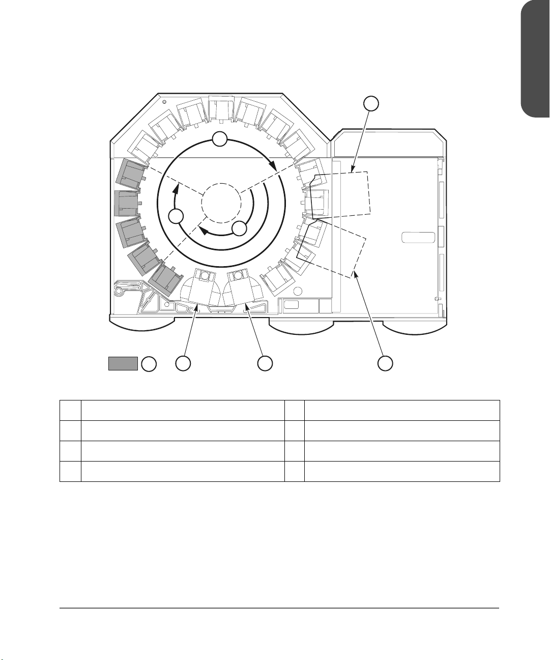
Figure 3 Locating Cartridges - Top View
3
2
1
Chapter 1
4
8
567
C 65127
1 1/3 capacity (partial access to Panel 2) 5 Drive column 1 (optional)
2 2/3 capacity (entire access to Panel 2) 6 CAP B (optional)
3 Full capacity (with optional expansion frame) 7 CAP A
4 Drive column 0 8 Panel 12
Chapter 1 Tape Library Components 21
Page 23
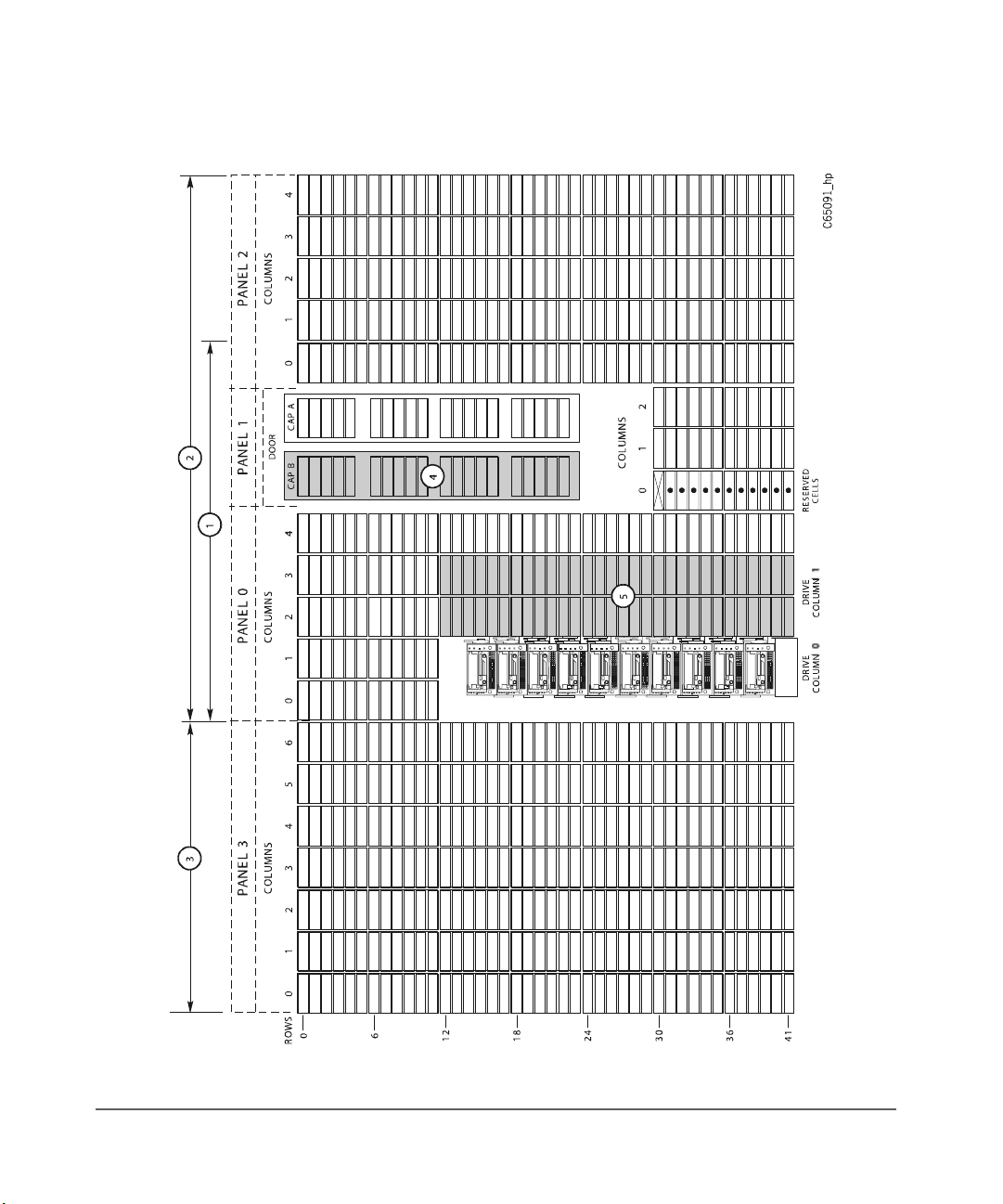
Figure 4 Locating Cartridges - Panels, Cells, Rows
22 Tape Library Components Chapter 1
Page 24

Table 2 Locating Cartridges - Panels, Cells, Rows (continued from Figure 4 on
page 22
)
1 228 cartridge cell configuration 4 Optional second CAP
Note: The optional second CAP replaces the
front window.
2 396 cartridge cell configuration 5 Optional second drive column
Note: The optional second drive column
replaces the 60 shaded cells.
3 Expansion frame
Note: 690 cartridge cell configuration
equals 396 cartridge cell configuration
plus an expansion frame.
Chapter 1
Chapter 1 Tape Library Components 23
Page 25

Reserved Cells
Figure 5 on page 25 shows the cells reserved for swapping cartridges and for
diagnostic and cleaning cartridges. The top cell is the swap cell, which is
reserved for in-transit cartridges. Do not place any cartridges into this cell. You
may place any type of cleaning or diagnostic cartridges into the other 11 cells.
Note Loading cleaning cartridges into any of these 11 cells enables
Auto Clean upon the next IPL.
Caution System degradation: Do not insert data cartridges into these
reserved cells. The host software will not find these cartridges.
24 Tape Library Components Chapter 1
Page 26

Figure 5 Reserved Cell Locations
DRIVE
COLUMN 1
Chapter 1
CAP ACAP B
1
2
3
C 65136
1 Location of reserved cells 3 Diagnostic and cleaning cartridges
2 Swap cell (leave empty)
Chapter 1 Tape Library Components 25
Page 27

Cartridge Access Port
A cartridge access port (CAP) is the location where you add cartridges to or
remove cartridges from a library without interrupting normal cartridge mounts
and dismounts by the robot. The library may have an optional, second CAP.
Both CAPs are located on the left front door.
The CAP magazine is designed for easy loading. You can access the
magazine by simply pulling down on the magazine handle and adding
cartridges. Or, you can remove the magazine by lifting it out, load the cells,
and place the magazine back into the CAP. Snap-on cartridge retention covers
allow you to keep cartridges in place when transporting magazines.
For detailed procedures, refer to Importing Data Cartridges through the CAP
on page 107 and Library Operation on page 93.
Drives
Note For drive and media information specific to your drive
The library can contain the following drive types:
■ HP Ultrium
technology, refer to Drives and Media on page 143.
■ Digital Linear Tape (DLT) 8000
■ 9840
26 Tape Library Components Chapter 1
Page 28

The maximum number of DLT or Ultrium drives is 20. The maximum number of
9840 drives is 12.
As an operator, you might have to:
■ Configure a drive in a library; refer to Drive Entries on page 76.
■ Check drive status information; refer to Drive Status on page 98.
■ Manually mount a cartridge to a drive or dismount a cartridge from a
drive; refer to Loading/Unloading Cartridges Manually on page 131.
Note During typical operation (or automated mode), the library’s
robotic hand-camera assembly automatically places a cartridge
into the drive or removes a cartridge from the drive when a
command is sent from the host software.
Chapter 1
Chapter 1 Tape Library Components 27
Page 29

Additional Components
Web-Based Library Administrator (WBLA)
The Web-Based Library Administrator (WBLA) incorporates a web interface to
the library. To use this feature, you will need a personal computer attached to
the library’s Ethernet port. This enables you to:
■ “View” the library interior and visually check the status of tapes, drives,
and CAP
■ Initiate diagnostic tests on the library from the personal computer
■ Make configuration changes or additions
Consult the Web-Based Library Administrator Online Help CD that shipped
with your library for more information.
Tape Library Safety Features
Safety features are incorporated into the tape library. If the left access door is
opened, an electrical interlock removes power from the robot assembly.
Behind the right front door, covers are placed over the logic card, the AC
power supply, and the DC power supply to prevent you from coming into
contact with hazardous voltages and sensitive electronics.
Controlling Software
Controlling software, within the client/server, requests tape read and write
operations to the drives and robotic move operations for the tape library
robotic components. Software determines where the cartridge is located by
tracking the VOLSER and cell location during audits, then allocates which drive
receives the cartridge. For specific information, refer to your software
publications.
28 Additional Components Chapter 1
Page 30

Library Operating Modes
An operating mode is the manner in which a tape library and the controlling
software (also referred to as the customer’s server software) interact. A library
can operate in either automated mode or manual mode.
Automated Mode
Automated mode is the normal operating mode of the tape library. The
controlling software instructs the robot to move the cartridge among the
storage cells, drives, and CAP without operator intervention. Your tasks may
include:
■ Monitoring the tape library operator display for messages
■ Importing a cartridge through the CAP
■ Exporting a cartridge through the CAP
■ Replacing a cleaning cartridge
Refer to Library Operation on page 93 for the procedures.
Chapter 1
Manual Mode
Manual mode refers to the tape library being inactive. Your tasks may include:
■ Opening the tape library doors
■ Moving the robot
■ Locating a cartridge
■ Removing a cartridge from the hand
■ Mounting a cartridge into a drive
■ Dismounting a cartridge from a drive
Refer to Library Operation on page 93 for the procedures.
Chapter 1 Library Operating Modes 29
Page 31

Auto Clean Feature
Note Ensure your backup software supports this feature before
Drives occasionally need to be cleaned to prevent read/write errors.
The Auto Clean feature is enabled when your tape library is initializing and
detects cleaning cartridges in the reserved cells. When a drive requires
cleaning while Auto Clean is enabled, the robot will receive a software
message telling it to retrieve a cleaning cartridge and place it into the drive.
If Auto Clean is not enabled, you must manually import a cleaning cartridge
for the drive that requires cleaning. The Clean Drive request appears on the
operator panel’s display.
Refer to For cleaning cartridge information specific to your drive type, see
Drives and Media on page 135. on page 88 for more information and
procedures.
Note For cleaning cartridge information specific to your drive
enabling.
technology, see Drives and Media on page 143.
30 Auto Clean Feature Chapter 1
Page 32

Accessory Bin
Chapter 1
You may use the internal 13U (0.57 m [22.75 in.] x 0.48 m [19 in.]) accessory
bin, located in the rack behind the right front door, for additional equipment.
Refer to Rack Safety and Precautions on page 199 for precautions you must
follow before installing equipment in this area.
Power cable space is provided in the cutout area of the rear door.
Note Heat within rack area: Cooling considerations should be made
based upon the power dissipation within the rack space, as well
as the external library room ambient conditions. Cooling must
be provided for moderate power dissipation within the rack
space.
Chapter 1 Accessory Bin 31
Page 33

32 Accessory Bin Chapter 1
Page 34

Controls and Indicators
This chapter describes the functions of the library operator panel, the library
power switch, and provides samples of displays you could see on the operator
panel display. It also lists tasks you can perform through the use of the
operator panel.
2
33
Page 35

Operator Panel
The operator panel, recessed into the library’s rack door, contains buttons,
indicators, and a graphic display. Figure 6 on page 36 shows the panel and
Table 3 on page 37 describes each item.
34 Operator Panel Chapter 2
Page 36

Use the operator panel to:
■ Monitor current information about the CAPs, configuration, drives, doors,
drive cleaning, hardware and software versions, personality, and library
status
■ Help resolve library problems
■ If an error occurs, the display shows a fault symptom code (FSC), which
you can give to a service representative to help resolve problems. Write
down the FSC as soon as it is displayed.
■ Set library, network, and drive configurations
■ Rotate the CAPs
■ Replace drive cleaning cartridges and set cleaning cartridge warning
count
■ Run library and drive tests
■ Reset the library (start an initial program load [IPL])
For specific task instructions, refer to Configuration on page 65 and Library
Operation on page 93.
Chapter 2
Chapter 2 Operator Panel 35
Page 37

Figure 6 Operator Panel Display, Controls, and Indicators
3
1
11
2
3
LIBRAR Y
ACTIVE
CAP
A
45 6 78
SERVICE
REQUIRED
OPENOPEN
CAP
B
ME N U SELE CT
RESE T
10
9
C 6508
36 Operator Panel Chapter 2
Page 38

Table 3 Operator Panel Display, Controls, and Indicators (continued from
Figure 6 on page 36)
1 Service Required indicator is steadily red
when human intervention is required.
7 [RESET] button, located behind the right front
door, starts an IPL.
Chapter 2
2 Library Active indicator flashes green when
the library is operational.
3 Open indicator is steadily amber when the
CAP is open for you to import or remove
cartridges.
4 [CAP A] open button rotates CAP A for you
to access the magazines.
5 [CAP B] open button rotates CAP B for you
to access the magazines.
6 [MENU] button initially places you into the
Main Menu screen; subsequently, it returns
you to a previously selected screen.
8 Arrow down button moves the cursor down
the display screen or decrements an
underscored value.
9 [SELECT] button selects an item on a menu; it
also saves the currently underscored value
and moves the cursor to the next field.
10 Arrow up button moves the cursor up the
display screen; it also increments a value
underscored on the screen.
11 Graphic display screen shows current
information, FSCs, and allows input from
menus.
Chapter 2 Operator Panel 37
Page 39

Indicators
Buttons
Three indicators provide basic status information: Library Active, Service
Required, and Open. Refer to Table 3 on page 37 for details about these
indicators.
Note When the Service Required indicator is on, contact your service
provider.
Seven buttons are provided on the operator panel: [CAP A], [CAP B], [RESET],
[MENU], [SELECT], and the up and down arrows. The [CAP] and [RESET]
buttons let you directly manipulate the library; the remaining four buttons let
you manipulate the menus and underscored values on the graphic display.
Refer to Figure 6 on page 36 and Table 3 on page 37 for the location and a
description of each button.
Note The up arrow, down arrow, [MENU] and [SELECT] buttons
manipulate only values that are under operator control. As you
scroll down or up a list of selections, the cursor underscores these
values. (You cannot manipulate values that do not permit
underscoring.)
38 Operator Panel Chapter 2
Page 40

Display Screens
Screens on the graphic display show current information and allow your input.
Information includes:
■ Drive status
■ CAP and CAP magazine status
■ Library status
■ Library capacity
■ Library personality
■ Library features
■ Hardware and software versions
■ SCSI type (single-ended or differential)
■ Cleaning cartridge and Auto Clean status
■ Ethernet ID
■ Error and FSC information
Note HP is transitioning the HP Surestore Tape Library Model 20/700
(product number A5597A) to allow for a new feature. This
feature will make it possible to couple two 20/700 libraries
together, allowing tape cartridges to be exchanged between the
libraries. As a result, we are transitioning to a new product
number, A5597B. Until this feature is available and installed, the
display on your library status screen will continue to identify the
library as “A5597A”. In the future, if you choose to use this
feature, your library will then be identified as “A5597B”.
Chapter 2
To determine whether your library is an A5597A or A5597B,
refer to the regulatory label on your unit.
Chapter 2 Operator Panel 39
Page 41

Except for CAP status and error or FSC information, these values are set
through an automatic configuration process that occurs during an IPL.
Values requiring your input are:
■ Cleaning cartridge warning count
■ SCSI drive configuration:
—SCSI ID
— Bus status (on or off bus)
■ Network configuration:
—Library name
— IP address
—Subnet mask
—Library gateway
■ Library configuration information:
—SCSI ID
— Fast Load enable/disable
—Date/time
■ Display screen brightness and contrast
You can also use the menus to run diagnostic tests.
The following pages describe the library’s primary menus. For instructions on
working with specific configuration values, see Operator Panel Entry on
page 70.
40 Operator Panel Chapter 2
Page 42

Library Status
The Library Status screen is an information-only screen. It is the first screen to
appear on the operator panel after an IPL.
Chapter 2
HP A5597A (CODE VERSION
X.XX.XX)
CAP (A) CLOSED CAP status
LIBRARY READY Library status
WEB ENABLED Remote access is available through the
COLUMN 0 The status of each drive in a specified
Figure 7 on page 41 shows an example Library Status screen. (For a list of
drive status messages, see Drive Status on page 98.)
Figure 7 Library Initial Status Screen
HP A5597A(CODE VER X.XX.XX)*
CAP CLOSED
LIBRARY READY
WEB ENABLED
COLUMN 0
00 BUSY
01 BUSY
02 LOADING
03 LOADING
04 EMPTY
05 EMPTY
06 EMPTY
07 --08 --09 ---
Library type and firmware version
Web-Based Library Administrator
(WBLA)
drive column
Chapter 2 Operator Panel 41
Page 43

Note With 3.00 firmware and higher, an asterisk (*) may appear on
the operator panel display. For example, HP A5597A (Code
3.00.xx)*. The asterisk (*) denotes the cleaning cartridge’s life
has expired. To determine which cartridge has expired and to
eject the expired cartridge, see For cleaning cartridge
information specific to your drive type, see Drives and Media
on page 135. on page 88, and Exporting Data Cartridges
through the CAP on page 112.
By pressing the [MENU] button from the Library Status screen, you can display
the Main Menu (see Figure 8 on page 42).
Figure 8 Main Menu Screen
MAIN MENU:
FSC LOG
CAP CONTENTS
DRIVE INFO
CLEANING INFO
DIAGNOSTICS
VERSION INFO
CONFIGURATION
42 Operator Panel Chapter 2
Page 44

FSC (Fault Symptom Code) Logs
The FSC Logs screen displays the last 20 fault symptom codes (FSCs), the
number of occurrences, and the date and time of the last occurrence. The
screen may be scrolled (if required) to view all FSCs. For more information,
Reviewing FSC Logs on page 114.
Note Events listed in the log might not be failures. All events are
recorded. FSCs are generated for both library and drive errors.
Chapter 2
Figure 9
.FSC Log Screen
3329 03 DRIVE_00_00
03/01/2001 14:46:14
3304 09 DRIVE_01_00
03/01/2001 14:46:14
30BB 02 NONE
03/01/2001 14:44:01
30BA 02 NONE
03/01/2001 14:44:01
30B9 02 DRIVE_02_00
02/28/2001 09:22:23
30B8 02 NONE
02/28/2001 08:27:14
4487 02 NONE
02/27/2001 16:52:33
3329 03 NONE
Chapter 2 Operator Panel 43
Page 45

CAP Contents
The CAP Contents screen is an information-only screen. It displays either the
VOLSER of a cartridge or status message for each slot in a CAP magazine.
The CAP status screen is shown in Figure 10 on page 44.
Note You must scroll down to view the contents of both CAPs.
Figure 10 CAP Status Screen
CAP A CONTENTS
MAGAZINE 1 CONTENTS
200042
57QF43R
EMPTY
EMPTY
EMPTY
MAGAZINE 2 CONTENTS
EMPTY
EMPTY
EMPTY
EMPTY
EMPTY
44 Operator Panel Chapter 2
Page 46

Drive Information
The Drive Information menu is an information-only screen that lists
manufacturing and status information about the selected drive (see Figure 11
on page 45):
VENDOR The manufacturer of the drive
TYPE The drive model
STATUS The drive’s local number and status (see Drive
Status on page 98 for a list of status messages)
SERIAL NUMBER The serial number assigned by the drive’s
manufacturer
INTERFACE TYPE The type of client-to-drive interface (a SCSI
interface)
CODE VERSION The firmware version of the drive
Note See Drive Information on page 99 for instructions on how to
access a drive. For information specific to your drive technology,
including troubleshooting, see Drives and Media on page 143.
Chapter 2
Figure 11 Drive Information Menu
DRIVE INFORMATION MENU:
VENDOR: HP
TYPE: HP LTO
STATUS: 00 EMPTY
SERIAL NUMBER:
XXXXXXXXXX
INTERFACE TYPE:
SCSI I/F
CODE VERSION
X.XX.XX
Chapter 2 Operator Panel 45
Page 47

Cleaning Information
The Cleaning Info menu provides information about and control of the
library’s cleaning cartridges. It enables you to change the warning count for
each type of cleaning cartridge. Figure 12 on page 47 shows an example of
the Cleaning Info menu:
NUM CLEAN
CARTRIDGES
DLT WARN COUNT The number times you want the DLT cleaning
9840 WARN COUNT The number times you want the 9840 cleaning
HP LTO WARN COUNT The number of times you want the Ultrium
EXPORT
CARTRIDGES
IMPORT
CARTRIDGES
CLEAN CARTRIDGE INFO A path to an information screen that lists all
The total number of cleaning cartridges
mounted in the reserved cells within the library
cartridge to be used before the library exports
it through the CAP (20 uses)
cartridge to be used before the library exports
it through the CAP (100 uses)
cleaning cartridge to be used before the
library exports it through the CAP (15 uses)
Note: The Ultrium universal cleaning cartridge
has a maximum of 50 uses.
A procedure for moving cleaning cartridges
from the reserved cells to the CAP
A procedure for moving cleaning cartridges
from the CAP to the reserved cells
cleaning cartridges in the library
The Cleaning Info menu lets you change the warning count for each type of
cleaning cartridge and import/export cleaning cartridges. It also lets you
check the number of times a cleaning cartridge has been used. For
procedures, see Library Operation on page 93.
46 Operator Panel Chapter 2
Page 48

Figure 12 Cleaning Information Menu
CLEANING INFO MENU:
NUM CLEAN CARTRIDGES: 00
DLT WARN COUNT: 0
00
9840 WARN COUNT: 000
HP LTO WARN COUNT: 000
EXPORT CARTRIDGES
IMPORT CARTRIDGES
CLEAN CARTIDGE INFO
Chapter 2
Chapter 2 Operator Panel 47
Page 49

Diagnostic Tests
Note Additional diagnostics are available from HP Library & Tape
Tools (see HP Library & Tape Tools on page 146 for more
information). Also, for troubleshooting information specific to
your drive technology, see Drives and Media on page 143.
All Diagnostic tests except for Clean Drive require the tape library and
associated drive to be inactive. The Main Diagnostics Menu (see Figure 13 on
page 49) lets you perform the following tests:
■ DRIVE DIAGNOSTICS:
— CLEAN DRIVE. Enables you to clean tape drives.
— MOUNT. Loads test tapes to a drive.
— DISMOUNT. Unloads test tapes from a drive.
— RUN DRIVE CHECK. Determines that the drive is in working order.
— MOUNT/DISMOUNT LOOP. Loads and unloads test tapes from a
drive. You may designate the number of times the tape library goes
through the loop.
Note HP does not recommend looping tests excessively.
■ GET-PUT LOOP. Gets a diagnostic tape and returns it to the same location.
You may designate the number of times the tape library goes through the
loop.
■ DEMO MODE. Simulates tape library operation.
For more information on using these tests, see Running Diagnostic Tests on
page 115.
48 Operator Panel Chapter 2
Page 50

Figure 13 Main Diagnostics Menu
MAIN DIAGNOSTICS MENU:
DRIVE DIAGNOSTICS
GET/PUT LOOP
DEMO MODE
Version Information
The Version Info Menu is an information-only screen (see example in Figure
14 on page 49). It displays the version level of the library’s functional code,
the date the code was completed, and the serial number of the logic card (also
referred to as “the MPC card”).
Figure 14 Version Information Menu
VERSION INFO MENU:
HP A5997A
CODE VERSION:
X.XX.XX
CODE BUILT ON:
(MONTH DAY YEAR TIME)
HARDWARE / VERSION
MPC XXXXXXXX
Chapter 2
Chapter 2 Operator Panel 49
Page 51

Configuration Menu
The Main Configuration Menu (see Figure 15 on page 50) allows you access
to the configuration menus (library, drive, network) and to the panel display
controls. You can access screens that let you view the library personality,
perform a feature upgrade, and input a password for a Web interface
product.
Figure 15 Configuration Menu
CONFIGURATION MENU
LIBRARY CONFIG
DRIVE CONFIG
NETWORK CONFIG
PERSONALITY MODULE
WEB PASSWORD
DISPLAY INFO
50 Operator Panel Chapter 2
Page 52

Library Configuration
The Lib Config Menu displays library capacity information and lets you modify
the library’s configuration.
The screen displays:
LIB SCSI I/F CONFIG Library interface identifier
FAST LOAD Fast Load feature status (on or off)
DATE Current date
TIME Current time
AUTO CLEAN Is Auto Clean enabled?
USER CELLS Number of data storage cells in the library
CAPS Number of CAPs installed
DRIVE COLUMN Number of drive columns installed
EXPANSION FRAME Is an expansion frame installed?
Figure 16 on page 51 shows an example library configuration screen. From
this menu, you may access editing menus for these library settings. See Library
Entries on page 70 for procedures and additional information.
Chapter 2
Figure 16 Library Configuration Menu
LIB CONFIG MENU:
LIB SCSI I/F CONFIG
FAST LOAD: OFF
DATE: 03/01/2001
TIME: 23:59
AUTO CLEAN: OFF
USER CELLS: 336
CAPS: 2
DRIVE COLUMN: 2
EXPANSION FRAME: NO
Chapter 2 Operator Panel 51
Page 53

Library SCSI Interface Configuration
The Lib SCSI I/F Config Menu lets you view the library’s SCSI type (differential
or single-ended) and access an edit menu for the library’s SCSI ID. Figure 17
on page 52 shows an example of this menu.
Figure 17 Library SCSI Interface Configuration Menu
LIB SCSI I/F CONFIG MENU:
SCSI ID: 0
SCSI TYPE: SE/LVD
0
52 Operator Panel Chapter 2
Page 54

Drive Configuration
The Drive Config Menu lets you modify each drive’s configuration. Figure 18
on page 53 shows an example screen. For each drive, the menu displays:
■ Drive position
■ Drive type
■ If the drive path is SCSI, the drive’s SCSI ID and its SCSI bus relationship
with the library.
Sub-menus let you change the SCSI ID and configure whether the drive is on
the same SCSI bus as the library. For more information, see Drive Entries on
page 76.
Note The cursor position is saved on all screens that list the library’s
drives.
The panel displays 16 lines of data per menu. If your library
contains more than eight drives, you must use the down arrow
button to scroll to drives 08 and above.
Figure 18 Drive Configuration Menu
SET DRIVE SCSI ID MENU:
Chapter 2
01 HP LTO ID: 02
VALID RANGE 0 - 15
SCROLL UP TO INCR
SCROLL DOWN TO DECR
SELECT TO SAVE
MENU TO EXIT
Chapter 2 Operator Panel 53
Page 55

Network Configuration
The Network Config Menu (see Figure 19 on page 54) lets you modify the
library’s network configuration and view the library’s Ethernet (web interface)
address. (At the time of publication, you cannot change the DHCP status.) For
procedures, see Network Entries on page 79.
Figure 19 Network Configuration Menu
NETWORK CONFIG MENU:
LIBRARY NAME:
_
IP ADDRESS:
000.000.000.000
NETWORK GATEWAY:
000.000.000.000
SUBNET MASK:
000.000.000.000
DNS CONFIGURATION
DMN
SVR PRIMARY
SVR SECONDARY
DHCP: DISABLED
ETHERNET ADDRESS:
00:10:4F:00:05:76
54 Operator Panel Chapter 2
Page 56

Personality Module
The Personality Module menu lets you view the library’s personality (vendor)
setting. The expanded screen in Figure 20 on page 55 illustrates how you can
check the Personality Module.
Note In the Personality Module menu, “HORIZON” refers to web
access and indicates whether or not it is enabled.
Figure 20 Personality Module Information
PERSONALITY MODULE INFO:
STATUS:
PRESENT
TYPE:
NORMAL
VERSION:
0
LIBRARY VENDOR ID:
1
LIBRARY VENDOR NAME:
HP
LIBRARY PRODUCT TYPE:
A5597A
HORIZON:
ENABLED
SCSI VENDOR NAME:
HP
SCSI PRODUCT NAME:
A5597A
Chapter 2
Chapter 2 Operator Panel 55
Page 57

Web Password
The Web Password menu item allows you to view or change your password.
See Figure 21 on page 56.
Figure 21 Web Password
WEB PASSWORD:
XXXXXXX
USE ARROWS TO CHANGE
EACH LETTER
SELECT TO MOVE RIGHT
SELECT ON SPACE TO
SAVE THE PASSWORD
MENU TO MOVE LEFT
OR TO EXIT
Display Information
The Display Info Menu (see Figure 22 on page 56) leads to menus that let you
adjust the contrast and backlight on the graphic display screen. For more
information, see Screen Characteristics on page 87.
Figure 22 Display Information Menu
DISPLAY INFO MENU:
CONTRAST: 09
DEFAULT = 16
BACKLIGHT: 128
DEFAULT = 128
RESTORE DEFAULTS
MENU TO EXIT
56 Operator Panel Chapter 2
Page 58

Operations Overview
Table 4 on page 58 lists the tasks that you can perform through the operator
panel menus. The right column refers you to another page in this manual for
more information. The options from the Main Menu include:
■ FSC LOGS
■ CAP CONTENTS
■ DRIVE INFO
■ CLEANING INFO
■ DIAGNOSTICS
■ VERSION INFO
■ CONFIGURATION
Chapter 2
Chapter 2 Operator Panel 57
Page 59

Table 4 Operations Guide
Task
Task Page for Operator Panel Instructions
TaskTask
Page for Operator Panel Instructions
Page for Operator Panel InstructionsPage for Operator Panel Instructions
Understand CAP status messages page 96
Understand library status messages page 97
Understand drive status messages page 98
Review FSC logs page 114
Check CAP magazine page 99
Manage cleaning cartridges See list for individual tasks.
■ Import cleaning cartridges through CAP page 105
■ Export cleaning cartridges to CAP page 104
■ Check usage count page 101
■ Check/set warning count page 88
■ Manually clean a drive page 112
■ Import data cartridges through CAP page 107
■ Export data cartridges through CAP page 112
Run diagnostic tests page 115
■ Run get/put loop page 117
■ Operate in demo mode page 118
■ Run drive mount diagnostics page 116
Check firmware version page 49
Check library personality information page 102
Set configuration page 70
■ Set library SCSI ID page 71
■ Enable/disable Fast Load page 73
58 Operator Panel Chapter 2
Page 60

Table 4
Operations Guide
Task
Task Page for Operator Panel Instructions
TaskTask
■ Set date and time page 74
■ Set drive configuration page 76
■ Set network configuration page 79
■ Set screen characteristics page 87
Page for Operator Panel Instructions
Page for Operator Panel InstructionsPage for Operator Panel Instructions
Chapter 2
Chapter 2 Operator Panel 59
Page 61

Library Power Switch
Note Be aware that each PDU supplies power to the robotics and half
The library power switch is a circuit breaker or breakers behind the right front
door of the library. Figure 23 on page 62 shows the power switch location.
This switch, attached to the AC power distribution unit (PDU), controls the AC
power to the library and drive column.
The power switch has two configurations:
■ A single breaker on the AC power distribution unit controls the library and
a single drive column.
■ A second breaker, located on the second power distribution unit, powers
the second drive column and an optional second library power supply.
of the drives. When the library has two PDUs (and a drive
column with two power cords), each PDU is connected to
separate branch AC circuit.
If you are installing multiple drives in the library (and the library
is a newer model with two power cords to the drive column), HP
recommends that you configure some drives in the upper five
slots, and some drives in the lower five slots in the drive column.
With this configuration, if one PDU loses power, some drives and
the library robotics will remain operational.
Note Your library has two circuit breakers:
The second PDU must be connected to a separate electrical
circuit.
If only one breaker is powered off, the second breaker will still
be powered on.
60 Library Power Switch Chapter 2
Page 62

To apply power to the library and drive column, lift the switch or switches.
To remove power from the library and drive column:
■ Make sure all jobs are complete.
■ Push down on the library power switch or switches.
Note The arrow in Figure 23 on page 62 shows moving the power
switch to the on position.
Chapter 2
Chapter 2 Library Power Switch 61
Page 63

Figure 23 Library Power Switch Location
62 Library Power Switch Chapter 2
Page 64

Tape Drive Power Switches
The tape drives are behind the drive access door, inside the right side door of
the library. Each drive has a power switch that controls the power to only that
drive.
Note The library’s main power switch controls the AC power to the
library and the drive column.
■ To remove power from a drive, push the drive switch to the “O” position.
■ To supply power to a drive, push the drive switch to the “|” position
Figure 24 Drive Power Switch Locations
1
Chapter 2
2
C 65131
1 DLT or Ultrium drive power switch 2 9840 drive power switch
Chapter 2 Tape Drive Power Switches 63
Page 65

64 Tape Drive Power Switches Chapter 2
Page 66

Configuration
This chapter describes how to configure the library and drives for operation.
Configuration requires you to:
1. Enable Auto Clean (if desired) by installing cleaning cartridges
2. Power on or reset the library
3. Enter library and drive configuration information
4. Send a client command to load library audit information into client
memory
After power-on, the library automatically verifies and loads some configuration
values, such as drive locations, Auto Clean status, capacity, and drive types.
Before the library is fully operational, however, someone must enter the
remaining configuration values.
Typically, your service representative will configure your library during
installation, during firmware upgrade, or after drives are added. If you must
change the library’s configuration, you may enter the values through the
operator panel.
3
Note You may need to consult with your systems administrator for
some information.
65
Page 67

Enabling Auto Clean
Note Ensure your backup software support this feature before
You will need to clean the drives occasionally to prevent read and write errors.
Enabling the Auto Clean feature allows the library to initiate drive cleaning
without your intervention. (A drive is cleaned with a special cleaning
cartridge.)
To enable Auto Clean, load valid cleaning cartridges into any of the 11 cells
that are reserved for cleaning and diagnostic cartridges. For the locations of
these cells, refer to Reserved Cells on page 24.
Note To be valid:
installing. For cleaning cartridge information specific to your
drive type, see Drives and Media on page 135.
A cleaning cartridge must have “CLN” in its VOLSER label.
9840 cleaning cartridges must also have a “U” on their media
ID labels.
HP Ultrium cartridges have unique bar code labels specific to HP
as the drive manufacturer. For more information, see Drives and
Media on page 143.
66 Enabling Auto Clean Chapter 3
Page 68

The Auto Clean feature is automatically enabled if you load even one cleaning
cartridge into the reserved cell area and then reset the library.
For instructions on how to use the CAP to insert cleaning cartridges, see
Importing Cleaning Cartridges through the CAP on page 105. For the
location of the reserved cells, see Reserved Cells on page 24.
To install cleaning cartridges in the reserved cells:
1. Unlock and open the front doors (see Opening the Library Front Doors on
page 122).
2. Verify that the cleaning cartridges are right side up (the VOLSER numbers
should be closest to the top edge and facing outward).
Caution Potential static electricity damage to electrical components. Take
precautions against electrostatic discharge by touching gray,
unpainted metal (such as the library’s frame) before reaching
into the library. Avoid touching any electrical component.
3. Place a cartridge into any of the 11 designated cells.
4. Close and lock the front access door.
Note You may follow this same procedure to load diagnostic
cartridges into the reserved cells. (Every diagnostic cartridge has
“DG” as the first two letters of its VOLSER.) However, loading
diagnostic cartridges alone does not enable Auto Clean.
Chapter 3
Chapter 3 Enabling Auto Clean 67
Page 69

Powering on the Library
Powering on the library supplies power to the library electronics and to the
drive column. If you have a second drive column, you must power on both
supplies. Powering on also initiates an IPL of the library.
To power on the library, lift the switch (circuit breaker) or switches behind the
right front door of the library. If you are not familiar with the location of the
switches, refer to Figure 23 on page 62.
Note If the tape library does not power on, contact your service
provider.
68 Powering on the Library Chapter 3
Page 70

Initializing and Resetting the Library
Powering on the library causes it to initialize components and perform an
Initial Program Load (IPL). During initialization, the library prepares the robot
for operation and audits any cartridges in the storage and reserved cells.
During an IPL, the library loads the operating code and automatically verifies
some configuration values, such as drive locations and drive types.
Re-initializing the Library
You will have to re-initialize the library in the rare instance when a robotic
component malfunctions. Before re-initializing the library, perform any
necessary manual operation tasks (see Manual Operation on page 121).
To re-initialize the library, make sure that all drives are powered on and
perform one of these actions:
■ Power off and power on the library (also causes an IPL)
■ Open and close the front door
Resetting the Library
You will have to reset the library when:
■ You are directed to do so by your system administrator or a service
representative
Chapter 3
■ You have to change the library configuration (for example, when you have
to change the library’s SCSI ID)
To reset the library after it is already powered on, make sure that all the drives
are powered on and press the [RESET] button on the operator panel.
Chapter 3 Initializing and Resetting the Library 69
Page 71

Entering Configuration Data
After the IPL is complete, the status screen will appear on the operator panel.
At this point, you must make choices about your library, drives, and network
and enter those choices into the library’s memory.
Note You may need to consult with your systems administrator for
some information.
You may enter all configuration data through the operator panel. See
Operator Panel Entry (in the following section) for specific instructions. Using
the Web-Based Library Administrator, you also can enter some configuration
data through a workstation or a PC that is running a Netscape or Microsoft
browser. For more information, access the online help files for the Web-Based
Library Administrator. They are available from the CD-ROM that shipped with
your product, or you can download them from www.hp.com/go/support.
Operator Panel Entry
Entering configuration data through the operator panel prepares the library
for operation. For a detailed description of the operator panel, see Operator
Panel on page 34.
Library Entries
Four entries are required for a library—other entries will vary with your
options:
■ Library SCSI ID
■ Drive Fast Load enable/disable
■ Date
■ Time
70 Entering Configuration Data Chapter 3
Page 72

Note The following procedures assume that you will make all entries
during one operator panel entry session. Each item is saved as it
is changed, except for the library’s SCSI ID: to save a revised
library SCSI ID, you must reset the library by pressing the
[RESET] button.
Setting the Library’s SCSI ID
Setting the Library’s SCSI ID
Setting the Library’s SCSI IDSetting the Library’s SCSI ID
If the control path for the library is SCSI, you must enter the library’s SCSI ID at
the operator panel. Set the library SCSI ID from the Lib SCSI I/F Config menu.
Note The information below explains special circumstances for
selecting a SCSI ID (address) for the library:
■ When configuring the library to a Unix-based workstation, HP
recommends that you use a dedicated SCSI client host bus adapter (HBA):
— For wide SCSI adapters, you may assign any address from 0 to 14 for
the library.
— For narrow SCSI adapters, the range of addresses is 0 to 6.
■ If you choose to use the embedded system bus on the SPARC station, select
address 6, 5, 2, or 0 for the library; the remaining targets are reserved for
Sun peripherals.
■ For RISC System/6000 machines, available addresses on the embedded
system bus are 6, 5, 3, and 2.
To set the library’s SCSI ID:
1. From the online status screen, press the [MENU] button.
The Main Menu will display.
Chapter 3
2. Press the down arrow button until the cursor underscores
CONFIGURATION.
3. Press the [SELECT] button.
The main Configuration Menu will appear and the cursor will line up with
LIBRARY CONFIG.
Chapter 3 Entering Configuration Data 71
Page 73

4. Press the [SELECT] button.
The Lib Config Menu will appear and the cursor will line up with LIB SCSI
I/F CONFIG.
5. Press the [SELECT] button.
The Lib SCSI I/F Config Menu will appear. (This menu also displays the
type of SCSI interface: differential or single-ended.)
6. Press the arrow buttons until the cursor underscores SCSI ID.
7. P r e s s t h e [SELECT] button.
The Set Lib SCSI ID Menu will appear.
8. Press the up and down arrow buttons to select the correct ID.
9. Press the [SELECT] button to save the changes. (You may press the [MENU]
button to abort.)
10. If the library SCSI ID is the only configuration value you wish to set at this
time, press the [RESET] button. If you wish to set other configuration values
before you reset the library, continue with the next section.
72 Entering Configuration Data Chapter 3
Page 74

Enabling/Disabling Fast Load
Enabling/Disabling Fast Load
Enabling/Disabling Fast LoadEnabling/Disabling Fast Load
These two terms are defined as follows:
Fast load on: The robot will mount a tape to a drive and then
immediately report the move completed.
Fast load off: The robot will mount a tape to a drive and wait at the
drive location until the tape is completely loaded before
reporting the move completed.
Note Some host software does not support the fast load enabled
option.
Enable or disable the Fast Load feature from the Lib Config Menu. To set either
feature:
1. At the Lib Config Menu screen, press the arrow button until the cursor
underscores FAST LOAD.
2. Press the [SELECT] button.
An editing screen appears.
3. Press the up and down arrow buttons to select either ON or OFF.
4. Press the [SELECT] button to save the changes. (You may press the [MENU]
button to abort.)
5. If you have already changed the library’s SCSI ID and are planning to exit
the main Configuration Menu at this time, you must press the [RESET]
button. If you want to set other configuration values, continue with the next
section.
If you have not changed the library’s SCSI ID and are not setting other
configuration values, press the [MENU] button until you exit all menus.
Chapter 3
Chapter 3 Entering Configuration Data 73
Page 75

Setting the Date
Setting the Date
Setting the DateSetting the Date
Set the date and time from the Lib Config Menu:
1. At the Lib Config Menu screen, press the arrow button until the cursor
underscores DATE.
2. Press the [SELECT] button.
An editing screen appears.
3. On the editing screen:
a. Press the up and down arrow buttons to select a value for each
portion (field) of the date.
b. Press the [SELECT] button to move right to the next field.
c. Press the [MENU] button to move left to the previous field.
4. When the screen displays your desired setting, press the [SELECT] button
from the right-most field to save the changes. You may press the [MENU]
button from the left-most field to abort.
5. If you have already changed the library’s SCSI ID and are planning to exit
the main Configuration Menu at this time, you must press the [RESET]
button. If you wish to set other configuration values, continue with the next
section.
6. If you have not changed the library’s SCSI ID and are not setting other
configuration values, press the [MENU] button until you exit all menus.
Setting the Time
Setting the Time
Setting the TimeSetting the Time
Set the time from the Lib Config Menu. FSC log entries correspond to this time
setting:
1. At the Lib Config Menu screen, press the arrow button until the cursor
underscores TIME.
2. Press the [SELECT] button.
An editing screen appears.
3. On the editing screen:
a. Press the up and down arrows to select a value for each portion (field)
of the time.
b. Press the [SELECT] button to move right to the next field.
c. Press the [MENU] button to move left to the previous field.
74 Entering Configuration Data Chapter 3
Page 76

4. When the screen displays your desired setting, press the [SELECT] button
from the right-most field to save the changes. (You may press the [MENU]
button from the left-most field to abort.)
5. If you have already changed the library’s SCSI ID and are planning to exit
the main Configuration Menu at this time, you must press the [RESET]
button. If you wish to set other configuration values, continue with the next
section.
6. If you have not changed the library’s SCSI ID and are not setting other
configuration values, press the [MENU] button until you exit all menus.
Setting the Web Password
Setting the Web Password
Setting the Web PasswordSetting the Web Password
If your library uses the Web-Based Library Administrator, you must set a Web
password at the operator panel. For instructions on setting this value, see Web
Password on page 56 and the Web-Based Library Administrator Online Help
CD that shipped with your library.
Chapter 3
Chapter 3 Entering Configuration Data 75
Page 77

Drive Entries
Note For 9840 drives only:
The drive’s SCSI ID and bus status can be entered from the
library’s operator panel if the drive has firmware version 1.24 or
higher. Check the drive’s firmware version, by selecting DRIVE
INFO from the Main Menu.
Configuring a 9840 drive might involve more than setting the
drive’s SCSI ID and bus status. For more information about 9840
drive configuration options and instructions, refer to the 9840
Tape Drive Service Manual.
Two entries complete the configuration options for each SCSI drive:
■ SCSI ID
■ Bus status (on or off bus)
Note “On Bus” means that the drive is on the same SCSI bus as the
library. “Off Bus” means that the drive is not on the same SCSI
bus as the library.
Set the drive SCSI IDs and bus status from the drive configuration menu. You
can enter both values for each drive at the same time:
1. At the main Configuration Menu, press an arrow button until the cursor
underscores DRIVE CONFIG.
2. Press the [SELECT] button.
The screen will list all installed drives, and the cursor will align with the first
drive on the list.
An example of the format is:
00 HP LTO ID: 01
ON BUS: ON
The first two digits are the drive’s logical number (the number that the
library has assigned the drive). The tape library sets this number during its
automatic configuration sequence (at power-on or reset). It is an internal
number only and is shown for information only.
76 Entering Configuration Data Chapter 3
Page 78

Note The uppermost drive within the column is designated as “0,” the
next is “1,” and so forth.
Next to the logical number is the drive type (DLT 8000 in this example). To
the right of the drive type is the ID or SCSI address. On the next line is the
drive’s bus status.
Ultrium drives will display as:
— HP LTO for Hewlett Packard Ultrium drives
Drive information might also appear on the menu as:
— INVALID if the drive’s SCSI ID is an invalid address
3. Press the arrow buttons to scroll to the drive you wish to change and press
the [SELECT] button.
The Set Drive SCSI ID Menu will appear.
Note The operator panel displays only 16 lines per menu. If the
library contains more than eight drives, you must use the down
arrow button to scroll to drives 09 and above.
4. Press the up and down arrow buttons to change the ID.
5. Press [SELECT] to save your changes.
Chapter 3
A message screen will appear to indicate that the library is saving the new
ID. Then the Drive Config Menu will reappear.
Note The new SCSI ID for a 9840 drive might not appear right away.
6. Press the arrow down button to get to the drive’s second line of
information (the drive’s bus status field).
7. P r e s s t h e [SELECT] button.
The Set Drive SCSI Bus Menu will appear.
8. Press the up and down arrow buttons to change the bus status to ON or
OFF.
Chapter 3 Entering Configuration Data 77
Page 79

9. Press the [SELECT] button to save the changes. (You may press the [MENU]
button to abort.)
The drive configuration screen will reappear.
10. Continue these steps until all drives are configured.
11. If you have already changed the library’s SCSI ID and are planning to exit
the main Configuration Menu at this time, you must press the [RESET]
button. If you wish to set other configuration values, continue with the next
section.
12. If you have not changed the library’s SCSI ID and are not setting other
configuration values, press the [MENU] button until you exit all menus.
78 Entering Configuration Data Chapter 3
Page 80

Network Entries
You may set the library’s network configuration, and view the library’s Ethernet
address from the Network Config Menu.
Note You may need to consult with the systems administrator for some
information.
The following entries set the library’s network configuration:
■ Library name
■ IP address
■ Network gateway
■ Subnet mask
■ Domain Name Service (DNS) Configuration
Note Domain Name Service (DNS) Configuration: You must enter the
(DNS) configuration only if your Simplified Network
Management Protocol (SNMP) agent is set to collect ("trap")
named recipients. If SNMP is set for numbered recipients, no
entries are required (see DNS Configuration on page 85).
Chapter 3
You also may view the library’s Ethernet address.
Chapter 3 Entering Configuration Data 79
Page 81

Viewing the Ethernet Address
Viewing the Ethernet Address
Viewing the Ethernet AddressViewing the Ethernet Address
This is a six-byte address, unique to each library. The address is written into
the MPC card at the factory and cannot be changed. An example of an
Ethernet address is 00:10:4f:00:05:01.
To view the Ethernet address:
1. At the Main Configuration Menu, press the arrow down button to line up
the cursor with NETWORK CONFIG.
2. Press the [SELECT] button.
The Network Config Menu will appear and the library’s Ethernet address
appears at the bottom of the screen.
3. If you have already changed the library’s SCSI ID and are planning to exit
the main Configuration Menu at this time, you must press the [RESET]
button. If you wish to set other configuration values, continue with the next
section.
If you have not changed the library’s SCSI ID and are not setting other
configuration values, press the [MENU] button until you exit all menus.
80 Entering Configuration Data Chapter 3
Page 82

Setting the Library Name
Setting the Library Name
Setting the Library NameSetting the Library Name
The system administrator might assign the library a name. The name is
mapped to the IP address but does not affect operation. To set the library
name:
1. At the Network Config menu, press an arrow button until the cursor
underscores LIBRARY NAME.
2. Press the [SELECT] button. An editing screen appears.
3. On the editing screen:
a. Use the up and down arrow buttons to select a value for each
character (field) in the name.
b. Use the [SELECT] button to move right to the next field.
c. Use the [MENU] button to move left to the previous field.
Note Do not enter a library name longer than 30 characters.
4. When the screen displays your desired setting, press the [SELECT] button
twice to save the changes. You may press the [MENU] button from the leftmost field to abort.
5. If you have already changed the library’s SCSI ID and are planning to exit
the main Configuration Menu at this time, you must press the [RESET]
button. If you wish to set other configuration values, continue with the next
section.
Chapter 3
If you have not changed the library’s SCSI ID and are not setting other
configuration values, press the [MENU] button until you exit all menus.
Chapter 3 Entering Configuration Data 81
Page 83

Setting the IP Address
Setting the IP Address
Setting the IP AddressSetting the IP Address
The system administrator might assign the library an IP address, which makes
the library accessible through a network. This is a four-byte address that must
be set with information obtained from the system administrator. The value set
identifies the library and makes it accessible through a network.
An example of an IP address entry is 192.0.0.1
Note To use the Web-Based Library Administrator, you must set the
library’s IP address at the operator panel.
To set the IP address:
1. At the Network Config Menu, press an arrow button until the cursor
underscores LIBRARY NAME.
2. Press the [SELECT] button. An editing screen appears.
3. On the editing screen:
a. Use the up and down arrow buttons to select a value for each three-
digit field in the address.
Note Do not leave the first field equal to zero (000).
b. Use the [SELECT] button to move right to the next field.
c. Use the [MENU] button to move left to the previous field.
4. When the screen displays your desired setting, press the [SELECT] button
from the right-most field to save the changes. You may press the [MENU]
button from the left-most field to abort.
5. If you have already changed the library’s SCSI ID and are planning to exit
the main Configuration Menu at this time, you must press the [RESET]
button. If you wish to set other configuration values, continue with the next
section.
If you have not changed the library’s SCSI ID and are not setting other
configuration values, press the [MENU] button until you exit all menus.
82 Entering Configuration Data Chapter 3
Page 84

Setting the Network Gateway Address
Setting the Network Gateway Address
Setting the Network Gateway AddressSetting the Network Gateway Address
A network gateway in a large network allows devices on one subnet to
interface with devices on another subnet (see Setting the Subnet Mask
Address on page 84). This four-byte address must be specified by the system
administrator.
Note Entering this address is optional. It sets up the gateway
connection between subnets, but it is applicable only when such
a connection exists and is necessary for library operation.
Consult with your systems administrator for additional
information.
To set the network gateway address:
1. At the Network Config Menu, press an arrow button until the cursor
underscores NETWORK GATEWAY.
2. Press the [SELECT] button.
An editing screen appears.
3. On the editing screen:
a. Press the up and down arrow buttons to select a value for each three-
digit field in the address.
b. Press the [SELECT] button to move right to the next field.
c. Press the [MENU] button to move left to the previous field.
4. Press the [SELECT] button from the right-most field to when the screen
displays your desired setting to save the changes. (You may press the
[MENU] button from the left-most field to abort.)
5. If you have already changed the library’s SCSI ID and are planning to exit
the main Configuration Menu at this time, you must press the [RESET]
button. If you wish to set other configuration values, continue with the next
section.
Chapter 3
If you have not changed the library’s SCSI ID and are not setting other
configuration values, press the [MENU] button until you exit all menus.
Chapter 3 Entering Configuration Data 83
Page 85

Setting the Subnet Mask Address
Setting the Subnet Mask Address
Setting the Subnet Mask AddressSetting the Subnet Mask Address
This is a four-byte notation (specified by the system administrator) to resolve
routing within your intranet. This address makes the library accessible through
a subnet on a large network. An example of a subnet mask entry is
255.255.254.0.
To set the subnet mask address:
1. At the Network Config Menu, press an arrow button until the cursor
underscores SUBNET MASK.
2. Press the [SELECT] button. An editing screen appears.
3. On the editing screen:
a. Press the up and down arrow buttons to select a value for each three-
digit field in the address.
b. Press the [SELECT] button to move right to the next field.
c. Press the [MENU] button to move left to the previous field.
4. Press the [SELECT] button from the right-most field when the screen
displays your desired setting to save the changes. (You may press the
[MENU] button from the left-most field to abort.)
5. If you have already changed the library’s SCSI ID and are planning to exit
the main Configuration Menu at this time, you must press the [RESET]
button. If you wish to set other configuration values, continue with the next
section.
If you have not changed the library’s SCSI ID and are not setting other
configuration values, press the [MENU] button until you exit all menus.
84 Entering Configuration Data Chapter 3
Page 86

DNS Configuration
DNS Configuration
DNS ConfigurationDNS Configuration
Note You must enter the Domain Name Service (DNS) configuration
only if your Simplified Network Management Protocol (SNMP)
agent is set to collect ("trap") named recipients. If SNMP is set
for numbered recipients, no entries are required.
Chapter 3
Setting the Domain
Name (DMN) Field
Setting the DNS
Server’s IP Address
The first entry you must make for the DNS Configuration is the Domain Name
(DMN) field.
1. Press the arrow button until the cursor underscores DMN.
2. Press the [SELECT] button. An editing screen appears.
3. On the editing screen:
a. Press the up and down arrow buttons to select a value for each letter
in the domain server’s name.
b. Press the [SELECT] button to move right to the next field.
c. Press the [MENU] button to move left to the previous field.
4. Enter the main server’s name, being sure to append .com at the end.
5. When the screen displays your desired setting, press the [SELECT] button
(from the right-most field) to save the changes.
Note You may press the [MENU] button from the left-most field to
abort.
The second entry you must make is the primary DNS server’s IP address.
1. Press the arrow button until the cursor underscores SVR Primary.
2. On the editing screen:
a. Press the up and down arrow buttons to select a value for each
number in the primary domain server’s IP address.
b. Press the [SELECT] button to move right to the next field.
c. Press the [MENU] button to move left to the previous field. Press the
[SELECT] button. An editing screen appears.
3. When the screen displays your desired setting, press the [SELECT] button
(from the right-most field) to save the changes.
Chapter 3 Entering Configuration Data 85
Page 87

Note You may press the [MENU] button from the left-most field to
abort.
Setting the
Secondary DNS
Server’s IP Address
The third entry you may make is the secondary DNS server’s IP address.
Note The secondary DNS server’s IP address is available for sites that
have a secondary (or backup) server. If your site does not have a
secondary server, this entry is not required.
1. Press the arrow button until the cursor underscores SVR Secondary.
2. On the editing screen:
a. Press the up and down arrow buttons to select a value for each
number in the secondary domain server’s IP address.
b. Press the [SELECT] button to move right to the next field.
c. Press the [MENU] button to move left to the previous field. Press the
[SELECT] button. An editing screen appears.
3. When the screen displays your desired setting, press the [SELECT] button
(from the right-most field) to save the changes.
Note You may press the [MENU] button from the left-most field to
abort.
If you are planning to exit the Main Configuration Menu at this time, you
must press the [RESET] button. If you wish to set other configuration values,
continue with the next section.
If you have not changed the library’s DNS configuration and are not
setting other configuration values, press the [MENU] button until you exit
all menus.
86 Entering Configuration Data Chapter 3
Page 88

Screen Characteristics
You also can change the operator panel’s screen characteristics from the main
Configuration Menu. The screen characteristics are saved in non-volatile
memory.
To change the contrast and backlight (or brightness) of the operator panel
screens:
1. At the Main Configuration Menu, press an arrow button until the cursor
underscores DISPLAY INFO.
2. Press the [SELECT] button. The Display Info Menu will appear.
3. Press the arrow buttons to line up with the desired screen characteristic:
CONTRAST or BACKLIGHT.
An editing screen will appear.
4. Press the up and down arrow buttons to change the count value.
Note To reset the screen characteristics to the default values, line up
the cursor with RESTORE DEFAULTS and press the [SELECT]
button.
5. Press the [SELECT] button to save the changes. (You may press the [MENU]
button to abort.)
Chapter 3
6. If you have already changed the library’s SCSI ID and are planning to exit
the main Configuration Menu at this time, you must press the [RESET]
button. If you try to exit the main configuration menu, a message will
appear requesting that you reset the library.
If you have not changed the library’s SCSI ID, you may exit the
configuration menu to do other tasks.
Chapter 3 Entering Configuration Data 87
Page 89

Cleaning Cartridge Warning Count
Note For cleaning cartridge information specific to your drive type,
see Drives and Media on page 135.
After a predetermined count, a cleaning cartridge must be replaced.
Note The Auto Clean feature is automatically enabled if you insert
even one cleaning cartridge into the reserved cell area and then
reset the library.
If the Auto Clean feature is enabled, use the operator panel to set the
maximum number of times a cleaning cartridge can be used (see Table 5 on
page 88).
Table 5
Cleaning Cartridge Warning Counts
Recommended Warning Counts
Recommended Warning Counts
Cleaning Cartridge Type
Cleaning Cartridge Type
Cleaning Cartridge TypeCleaning Cartridge Type
LP LTO Ultrium 15 uses
LP LTO Ultrium
(universal)
DLT 8000 20 uses
9840 100 uses
Note With 3.00 firmware and higher, an asterisk (*) may appear on
the operator panel display. For example, HP A5597A (Code
3.00.xx)*. The asterisk (*) denotes the cleaning cartridge’s life
has expired. To determine which cartridge has expired and to
eject the expired cartridge, see For cleaning cartridge
information specific to your drive type, see Drives and Media
on page 135. on page 88, and Exporting Data Cartridges
through the CAP on page 104.
Recommended Warning Counts Recommended Warning Counts
(maximum)
(maximum)
(maximum)(maximum)
50 uses
88 Entering Configuration Data Chapter 3
Page 90

You set the cleaning cartridge warning count from the main menu screen. To
set this number:
1. From the online status screen, press the [MENU] button. The main menu
screen will appear.
2. Press the arrow button until the cursor lines up with CLEANING INFO.
3. Press the [SELECT] button.
The CLEANING INFO screen will appear. It displays the number of
cleaning cartridges in the reserved area at initialization.
4. Press an arrow button until the cursor is at the appropriate drive’s WARN
COUNT.
5. Press the [SELECT] button for your choice.
An editing screen will appear. The editing screen will display the current
setting for the cartridge warning count. The maximum recommended
warning count is shown below the current setting.
6. Press the arrow buttons to change the warning count.
7. P r e s s th e [SELECT] button to save the changes. (You may press the [MENU]
button to abort.)
8. Press the [MENU] button to return to the library status screen.
Chapter 3
Chapter 3 Entering Configuration Data 89
Page 91

Web-Based Library Administrator (WBLA)
The Web-Based Library Administrator is a web-based interface to the library.
Your service representative should install it for you. Before you can use the
Web-Based Library Administrator to monitor the library or alter the library’s
configuration, your service representative must enter two values at the operator
panel:
■ The library’s IP address
■ The library’s Web password
For instructions on how best to make these entries, see the documentation
included in the Web-Based Library Administrator shipping package. For
instructions on using the interface to alter the library’s configuration or monitor
library activity, access the online help files for the Web-Based Library
Administrator. They are available from the CD that shipped with your product,
or you can access them from www.hp.com/go/support.
90 Entering Configuration Data Chapter 3
Page 92

Loading Tapes into the Library
When you are ready to place the library into production, you may load data
cartridges inside the library. The most efficient way to load a great quantity of
tapes into the library is to manually load them into the cells.
Figure 25 on page 91 and Figure 26 on page 92 illustrate how cartridges are
placed into cells.
Figure 25 Placing Tapes into Array Cells - Ultrium and DLT
Chapter 3
1 Ultrium cartridge 3 DLT cartridge
2 Ultrium cartridge label 4 DLT cartridge label
Chapter 3 Loading Tapes into the Library 91
Page 93

Figure 26 Placing Tapes into Array Cells - 9840
1
2
1 9840 cartridge 2 9840 cartridge label
Note Use only cartridges designed for your type of tape drives.
You must first unlock and open the main access door. This procedure is
explained in Opening the Library Front Doors on page 122.
You may also load cartridges into array cells by using the CAP(s). While this
method is more time-consuming to fully populate the library, the procedure is
explained in Importing Data Cartridges through the CAP on page 107.
After you have loaded all the cartridges, close and lock the main door. The
robot will automatically audit the cartridges and their locations within the
library.
92 Loading Tapes into the Library Chapter 3
Page 94

Library Operation
This chapter contains the procedures for operating the library in:
■ Automated mode
■ Manual mode
4
93
Page 95

Operating in Automated Mode
Automated mode is the normal operating mode of the library. When the
library is active and the robot is mounting and dismounting cartridges,
monitor your operator console and the library operator panel for messages
and respond appropriately.
When a tape library is active, you also might need to:
■ Monitor the operator panel for status messages
■ Export cleaning cartridges
■ Import cleaning cartridges
■ Import cartridges into the library through CAP
■ Export cartridges from the tape library through the CAP
■ Replace a cleaning cartridge
■ Manually clean a drive
■ Review the FSC log
■ Run diagnostic tests
The following section describes how to perform these activities.
Monitoring Status Information
You can monitor CAP, library, remote user, and drive status information
through the library status screen (see Figure 27 on page 95). This is the main
screen on the operator panel. It displays after initialization is complete and
also when you press the [MENU] button while viewing the Main Menu.
You also can monitor drive information, CAP magazine status, the cleaning
cartridge usage count, and the library’s “personality” information through
operator panel menus.
94 Operating in Automated Mode Chapter 4
Page 96

Figure 27 Example Library Status Screen
HP A5597A(CODE VER X.XX.XX)
CAP A CLOSED
LIBRARY READY
WEB ENABLED
COLUMN 0
00 EMPTY
01 EMPTY
02 EMPTY
03 EMPTY
04 EMPTY
05 LOADED
06 LOADED
07 EMPTY
08 EMPTY
--
Chapter 4
Chapter 4 Operating in Automated Mode 95
Page 97

CAP Status
The first line of status information on the library status screen indicates the
condition of the CAP. Table 6 on page 96 explains the messages that might
appear on this line.
Table 6
CAP Status Messages
Message
Message Explanation
MessageMessage
OPEN The CAP door is currently open. (The Open
indicator light also is on.) You may insert
cartridges or remove the CAP magazines. But you
cannot view the CAP magazine contents through
the operator panel menus.
CLOSED The CAP door is currently closed.
CLOSED (LOCKED) The CAP door is currently closed and locked.
Before you can open the CAP door, you must issue
a command from your system console.
TRANSITION The CAP door has stalled while attempting to
open.
UNKNOWN The library does not recognize the current state of
the CAP door.
Explanation
ExplanationExplanation
96 Operating in Automated Mode Chapter 4
Page 98

Library Status
The library status line indicates the current state of the library. Table 7 on
page 97 explains the messages that might appear on this line.
Table 7
Library Status Messages
Message
Message Explanation
MessageMessage
LIB MAIN DOOR OPEN The library’s front door is open. When
you close it, the library will reset
(initialize).
LIB INIT REQUIRED The library requires initialization. You
must press the [RESET] button.
LIBRARY NOT READY The library is not available to perform
operator-requested actions. Some status
information might be available through
the network interfaces.
LIBRARY READY The library has completed initialization
and is ready to perform requested
actions.
LIB MAINTENANCE MODE The library is offline because it is
performing diagnostic tests.
INTERVENTION REQUIRED The library is experiencing a problem.
You should note the FSC (if the library
has issued one) and call your service
representative.
Explanation
ExplanationExplanation
Chapter 4
LIB UNKNOWN STATE The library does not recognize its current
state. You should note the FSC (if the
library has issued one) and call your
service representative.
Web Status
Following the library status line is a message indicating that the Web-Based
Library Administrator (WBLA) is enabled. For more information on the WBLA,
see Web-Based Library Administrator (WBLA) on page 28.
Chapter 4 Operating in Automated Mode 97
Page 99

Drive Status
Table 8 on page 98 summarizes drive status messages that might appear on
the library status screen:
Table 8 Drive Status Messages
Message
Message Explanation
MessageMessage
INIT REQUIRED You must initialize this drive.
NOT CONNECTED This drive is not connected to a SCSI bus.
UNKNOWN DRIVE The library does not recognize the type of drive in
NOT COMMUNICATE This drive is not communicating with the client or
NOT FUNCTIONAL This drive is not operating properly.
NOT LOADABLE The library cannot load a cartridge into this drive.
EMPTY This drive does not have a tape loaded.
CARTRIDGE IN The drive contains a cartridge, but the cartridge is
Explanation
ExplanationExplanation
this location.
the drive power is off.
not loaded into the drive.
CLEAN NEEDED This drive requires cleaning.
CLEAN FAILED The attempt to clean this drive failed.
LOADING The library is mounting a cartridge to this drive.
REWOUND The cartridge in this drive has been rewound.
UNLOADING The library is dismounting a cartridge from this
drive.
LOADED The library has loaded a cartridge into this drive.
REWINDING The cartridge in this drive is being rewound.
BUSY This drive is performing a read or write operation.
CLEANING The drive is being cleaned.
98 Operating in Automated Mode Chapter 4
Page 100

Note The operator panel displays only 16 lines per screen. If the
library contains more than eight drives, you must use the down
arrow button to scroll to Drives 08 and above.
Drive Information
To view details about an installed drive, including its serial number and
firmware version:
1. Press the [MENU] button to display the Main Menu.
2. If necessary, press an arrow button until the cursor lines up with DRIVE
INFO.
3. Press the [SELECT] button.
A list of all installed drives will appear.
4. Use the arrow buttons until the cursor underscores the desired drive.
5. Press the [SELECT] button.
The Drive Information Menu will appear (see Figure 11 on page 45). The
screen lists the manufacturer, model, status, serial number, interface type,
and firmware version of the selected drive. See Table 8 on page 98 for a
list of drive status messages.
CAP Magazine Status
Chapter 4
To check the status of a CAP magazine and its contents:
1. Press the [MENU] button to display the Main Menu.
2. If necessary, press an arrow button until the cursor lines up with CAP
CONTENTS.
3. Press the [SELECT] button.
The CAP Contents menu will appear. The screen lists the VOLSER of each
cartridge in an installed magazine or it lists a status message. See Table 9
on page 100 for the status messages that appear on this list.
Note Each CAP has four magazines, numbered one through four,
from the top location to the bottom.
Chapter 4 Operating in Automated Mode 99
 Loading...