

Page 1
StorageTek
Page 2

Page 3

Page 4

Printing History
New editions of this guide incorporate all material updated since the previous edition.
The manual printing date and part number indicate the current edition. The printing
date changes when a new edition is printed. (Minor corrections and updates
incorporated at reprint do not cause the date to change.)
1 November 1997 Edition 1
23 February 1998 Edition 2
15 May 1999 Edition 3
© 1997 through 1999 by Storage Technology Corporation and Hewlett-Packard Company. All rights reserved.
ii
Page 5

List of Pages
Document Title: A4845A LSM Hardware Operator’s Guide
Manufacturing Doc PN: A4845-96014
Customer Doc PN: A4845-90000
Vendor PN: 95762
Edition 1: 1 November 1997, EC 83907
Edition 2: 23 February 1998, EC 83963, KIT PN 80967
Edition 3: 15 May 1999, EC 53855, KIT PN 14691
This document contains 92 pages:
Section Disposition
Cover Replace
Blank Page entire
Title Page guide
Copyright
iii through xxii
1-1 through 1-10
2-1 through 2-10
3-1 through 3-22
4-1 through 4-8
A-1 through A-10
Glossary-1 through Glossary-2
Index-1 through Index-4
Reader’s Comment Form
Business Reply Mailer
Blank Page
Back Cover
iii
Page 6

List of Pages
This page intentionally left blank.
iv
Page 7

Regulatory Statements
Regulatory Statements
■ FCC Radio Frequency Interference Statement
(USA)
Note: This equipment generates, uses and can radiate radio frequency energy.
If it is not installed and used in accordance with the instruction manual,
it may cause interference to radio communications. It has been tested
and found to comply with the limits for a Class A computing device
pursuant to Part 15 of FCC rules, which are designed to provide
reasonable protection against interference when operated in a
commercial environment. Operation of this equipment in a residential
area is likely to cause interference, in which case the user, at his own
expense, will be required to take whatever measures necessary to
correct the interference.
Hewlett-Packard’s device certification tests were conducted with HP
computer systems and HP shielded cables, such as those received with
your product. Changes or modifications not expressly approved by
Hewlett-Packard could void the user’s authority to operate the
equipment. Cables used with this device must be properly shielded to
comply with the requirements of the FCC.
■ IEC Statement (Worldwide)
Note: This is a Class A product. In a domestic environment, this product may cause
radio interference, in which case the user may be required to take adequate
measures.
■ EMC Statement (Canada)
Note: This Class A digital apparatus meets all requirement of the Canadian
Interference-Causing Equipment Regulations.
Cet appareil numérique de la Classe A respecte toutes les exigences du
Réglement sur le matériel brouelleur du Canada.
■ General Approval (U.K.)
Note: The Hewlett-Packard A4845A DLT Library is approved under approval
number NS/G/1234/J/100003 for indirect connection to Public
Telecommunication Systems in the U.K.
v
Page 8
Regulatory Statements
■ Herstellerbescheinigung (Germany)
Note: Diese Information steht im Zusammenhang mit den Anforderungen der
Maschinenlärm information sverordnung vom 18 Januar 1991.
• Schalldruckpegel Lp # 70 dB(A)
• Am Arbeitsplatz
• Normaler Betrieb
• Nach ISO 7779:1988/EN 27779:1991 (Typprüfung)
■ VCCI Class A (Japan)
Note: This equipment is in the Class A category information technology
equipment based on the rules of Voluntary Control Council For
Interference by Information Technology Equipment (VCCI). When used
in a residential area, radio interference may be caused. In this case, user
may be required to take appropriate corrective actions.
Consequently, when used in residential area or in an adjacent area thereto,
radio interference may be caused to radios and TV receivers, etc. Read the
instructions for correct handling.
vi
Page 9
■ Harmonics Conformance (Japan)
This product conforms Power Line Harmonics guidelines for the User’s manual
display. No product labeling required for JAPAN.
■ Taiwan Warning Label Statement
The following is the warning label statement from Taiwan, R.O.C.:
Regulatory Statements
vii
Page 10

Regulatory Statements
■ European Compliance Statement
The following is the compliance statement from Europe:
DECLARATION OF CONFORMITY
according to ISO/IEC Guide 22 and EN 45014
Manufacturer’s Name:Hewlett-P ackard Company
Enterprise Storage Solutions Division
Manufacturer’s Address:8000 Foothill s Blvd.
Roseville, CA 95747
USA
declares, that the product
Product Name: Automated Tape Library Model 10/588 or
HP SureStore E Tape Library 10/588
Order Number:A4845A
Product Options:all
conforms to the following Product Specifications:
Safety: IEC 950:1991 + A1, A2, A3, A4 / EN 60950:1992 + A1, A2, A3, A4
GB 4943-1 995
IEC 825-1:1993 / EN 60825-1:1993, Class 1
EMC: CISPR 22:1993 +A1, A2 / EN 55022:1994+A1, A2 - Class A
GB 9254-1 988
EN 50082-1:1992
IEC 801-2:1991 / prEN 55024-2:1992,4 kV CD, 8 kV AD
IEC 801-3:1984 / prEN 55024-3:1991,3 V/m
IEC 801-4:1988 / prEN 55024-4:1993,0.5 kV Signal Lines
1 kV Power Lines
IEC 1000-3-2:1995 / EN 61000-3-2:1995, Class D, Harmonics
IEC 1000-3-3:1994 / EN 61000-3-3:1995, Flicker
Supplementary Information:
The product herewith complies with the requirements of the Low Voltage
Directive 73/23/EEC and the EMC Directive 89/336/EEC and carries the CE
marking accordingly.
The Product was tested in a typical configuration with multiple PC based SCSI
emulators.
1
Roseville, April 8, 1999
European Contact: Your local Hewlett-Packard Sales and Service Office or Hewlett-Packard GmbH,
Department HQ-TRE, Herrenberger Straße 130, D-71034 Böblingen (FAX: + 49-7031-14-3143)
viii
Page 11

Contents
List of Pages . . . . . . . . . . . . . . . . . . . . . . . . . . . . . . . . . . . . . . . . . . iii
Regulatory Statements . . . . . . . . . . . . . . . . . . . . . . . . . . . . . . . . . . v
FCC Radio Frequency Interference Statement (USA) . . . . . . . . . . . . . . . . . . . . . . . . . v
IEC Statement (Worldwide) . . . . . . . . . . . . . . . . . . . . . . . . . . . . . . . . . . . . . . . . . . . v
EMC Statement (Canada) . . . . . . . . . . . . . . . . . . . . . . . . . . . . . . . . . . . . . . . . . . . . . v
General Approval (U.K.) . . . . . . . . . . . . . . . . . . . . . . . . . . . . . . . . . . . . . . . . . . . . . v
Herstellerbescheinigung (Germany) . . . . . . . . . . . . . . . . . . . . . . . . . . . . . . . . . . . . vi
VCCI Class A (Japan) . . . . . . . . . . . . . . . . . . . . . . . . . . . . . . . . . . . . . . . . . . . . . . vi
Harmonics Conformance (Japan) . . . . . . . . . . . . . . . . . . . . . . . . . . . . . . . . . . . . . . vii
Taiwan Warning Label Statement . . . . . . . . . . . . . . . . . . . . . . . . . . . . . . . . . . . . . . vii
European Compliance Statement . . . . . . . . . . . . . . . . . . . . . . . . . . . . . . . . . . . . . .viii
Contents . . . . . . . . . . . . . . . . . . . . . . . . . . . . . . . . . . . . . . . . . . . . . ix
Figures . . . . . . . . . . . . . . . . . . . . . . . . . . . . . . . . . . . . . . . . . . . . . xiii
Tables . . . . . . . . . . . . . . . . . . . . . . . . . . . . . . . . . . . . . . . . . . . . . . . xv
About This Guide . . . . . . . . . . . . . . . . . . . . . . . . . . . . . . . . . . . . .xvii
Organization . . . . . . . . . . . . . . . . . . . . . . . . . . . . . . . . . . . . . . . . . . . . . . . . . . . . xvii
Important Messages . . . . . . . . . . . . . . . . . . . . . . . . . . . . . . . . . . . . . . . . . . . . . .xviii
Related Publications . . . . . . . . . . . . . . . . . . . . . . . . . . . . . . . . . . . . . . . . . . . . . .xviii
Servicing . . . . . . . . . . . . . . . . . . . . . . . . . . . . . . . . . . . . . . . . . . . . . . . . . . . . . . xviii
Warranty . . . . . . . . . . . . . . . . . . . . . . . . . . . . . . . . . . . . . . . . . . . . . . . . . . . . . . . xviii
Grounding . . . . . . . . . . . . . . . . . . . . . . . . . . . . . . . . . . . . . . . . . . . . . . . . . . . . . .xix
Internal Code License . . . . . . . . . . . . . . . . . . . . . . . . . . . . . . . . . . . . . . . . . . . . . . xx
General Information . . . . . . . . . . . . . . . . . . . . . . . . . . . . . . . . . . 1-1
Library Storage Module Components . . . . . . . . . . . . . . . . . . . . . . . . . . . . . . . . . . .1-1
Robot . . . . . . . . . . . . . . . . . . . . . . . . . . . . . . . . . . . . . . . . . . . . . . . . . . . . . . .1-1
Storage Cells . . . . . . . . . . . . . . . . . . . . . . . . . . . . . . . . . . . . . . . . . . . . . . . . . .1-4
Cartridge Access Port . . . . . . . . . . . . . . . . . . . . . . . . . . . . . . . . . . . . . . . . . . . .1-7
ix
Page 12

Contents
Drives . . . . . . . . . . . . . . . . . . . . . . . . . . . . . . . . . . . . . . . . . . . . . . . . . . . . . .1-7
LSM Safety Features . . . . . . . . . . . . . . . . . . . . . . . . . . . . . . . . . . . . . . . . . . . . . . .1-7
Controlling Software . . . . . . . . . . . . . . . . . . . . . . . . . . . . . . . . . . . . . . . . . . . . . . 1-7
Library Operating Modes . . . . . . . . . . . . . . . . . . . . . . . . . . . . . . . . . . . . . . . . . . . .1-8
Automated Mode . . . . . . . . . . . . . . . . . . . . . . . . . . . . . . . . . . . . . . . . . . . . . . 1-8
Manual Mode . . . . . . . . . . . . . . . . . . . . . . . . . . . . . . . . . . . . . . . . . . . . . . . . . 1-8
AUTO CLEAN Feature . . . . . . . . . . . . . . . . . . . . . . . . . . . . . . . . . . . . . . . . . . . . . . 1-8
Controls, Indicators, and Configuration . . . . . . . . . . . . . . . . . . 2-1
LSM Operator Panel . . . . . . . . . . . . . . . . . . . . . . . . . . . . . . . . . . . . . . . . . . . . . . . 2-1
Setting the SCSI Address . . . . . . . . . . . . . . . . . . . . . . . . . . . . . . . . . . . . . . . . . . . .2-3
Setting Cleaning Cartridge Count . . . . . . . . . . . . . . . . . . . . . . . . . . . . . . . . . . . . . . 2-7
Power Switch . . . . . . . . . . . . . . . . . . . . . . . . . . . . . . . . . . . . . . . . . . . . . . . . . . . .2-9
Operating the LSM . . . . . . . . . . . . . . . . . . . . . . . . . . . . . . . . . . . . 3-1
Powering On or IPLing the LSM . . . . . . . . . . . . . . . . . . . . . . . . . . . . . . . . . . . . . . 3-1
Powering Off the LSM . . . . . . . . . . . . . . . . . . . . . . . . . . . . . . . . . . . . . . . . . . . . . . 3-3
Operating in Automated Mode . . . . . . . . . . . . . . . . . . . . . . . . . . . . . . . . . . . . . . .3-3
Entering Cartridges through the CAP . . . . . . . . . . . . . . . . . . . . . . . . . . . . . . . . 3-3
Ejecting Cartridges through the CAP . . . . . . . . . . . . . . . . . . . . . . . . . . . . . . . .3-5
Replacing the Cleaning Cartridge . . . . . . . . . . . . . . . . . . . . . . . . . . . . . . . . . . .3-5
Operating in Manual Mode . . . . . . . . . . . . . . . . . . . . . . . . . . . . . . . . . . . . . . . . . .3-7
Opening the LSM Front Doors . . . . . . . . . . . . . . . . . . . . . . . . . . . . . . . . . . . . .3-7
Moving the Robot . . . . . . . . . . . . . . . . . . . . . . . . . . . . . . . . . . . . . . . . . . . . . .3-9
Locating a Cartridge in the Storage Cells . . . . . . . . . . . . . . . . . . . . . . . . . . . . 3-12
Removing a Cartridge from the Hand . . . . . . . . . . . . . . . . . . . . . . . . . . . . . . . 3-14
Mounting a DLT Cartridge into a Drive . . . . . . . . . . . . . . . . . . . . . . . . . . . . . 3-17
Mounting a Cartridge into a 9840 Drive . . . . . . . . . . . . . . . . . . . . . . . . . . . . . 3-20
Dismounting a Cartridge from a DLT Drive . . . . . . . . . . . . . . . . . . . . . . . . . . 3-21
Dismounting a Cartridge from a 9840 Drive . . . . . . . . . . . . . . . . . . . . . . . . . . 3-22
Returning the LSM to Online Status . . . . . . . . . . . . . . . . . . . . . . . . . . . . . . . . 3-22
Cartridges . . . . . . . . . . . . . . . . . . . . . . . . . . . . . . . . . . . . . . . . . . . 4-1
Preparing Cartridges . . . . . . . . . . . . . . . . . . . . . . . . . . . . . . . . . . . . . . . . . . . . . . .4-1
Handling a Cartridge . . . . . . . . . . . . . . . . . . . . . . . . . . . . . . . . . . . . . . . . . . . . 4-1
Inspecting a Cartridge . . . . . . . . . . . . . . . . . . . . . . . . . . . . . . . . . . . . . . . . . . . 4-1
Applying DLT Cartridge Labels . . . . . . . . . . . . . . . . . . . . . . . . . . . . . . . . . . . .4-3
Applying 9840 Cartridge Labels . . . . . . . . . . . . . . . . . . . . . . . . . . . . . . . . . . . .4-4
Setting the DLT Write-Protect Switch . . . . . . . . . . . . . . . . . . . . . . . . . . . . . . . . 4-6
Setting the 9840 Write-Protect Switch . . . . . . . . . . . . . . . . . . . . . . . . . . . . . . . .4-7
x
Page 13

Contents
Maintaining Cartridges . . . . . . . . . . . . . . . . . . . . . . . . . . . . . . . . . . . . . . . . . . . . . .4-8
Storing Cartridges . . . . . . . . . . . . . . . . . . . . . . . . . . . . . . . . . . . . . . . . . . . . . .4-8
Cleaning the Cartridge Exterior . . . . . . . . . . . . . . . . . . . . . . . . . . . . . . . . . . . .4-8
Specifications . . . . . . . . . . . . . . . . . . . . . . . . . . . . . . . . . . . . . . . A-1
Supplies and Accessories . . . . . . . . . . . . . . . . . . . . . . . . . . . . . . . . . . . . . . . . . A-1
Ordering DLT Cartridge Labels . . . . . . . . . . . . . . . . . . . . . . . . . . . . . . . . . . . . . . A-3
Basic Requirements for Cartridges . . . . . . . . . . . . . . . . . . . . . . . . . . . . . . . . . . . . A-5
DLT Cartridge Environmental Specifications . . . . . . . . . . . . . . . . . . . . . . . . . . A-6
9840 Cartridge Environmental Specifications . . . . . . . . . . . . . . . . . . . . . . . . . . A-7
LSM Specifications . . . . . . . . . . . . . . . . . . . . . . . . . . . . . . . . . . . . . . . . . . . . . . . . A-8
Agency Certifications . . . . . . . . . . . . . . . . . . . . . . . . . . . . . . . . . . . . . . . . . . . . . A-10
Glossary . . . . . . . . . . . . . . . . . . . . . . . . . . . . . . . . . . . . . . Glossary-1
Index . . . . . . . . . . . . . . . . . . . . . . . . . . . . . . . . . . . . . . . . . . Index-1
xi
Page 14

Contents
This page intentionally left blank.
xii
Page 15

Figures
Figures
Figure 1-1. LSM Major External Components . . . . . . . . . . . . . . . . . . . . . . . . . . . . . . . .1-2
Figure 1-2. Robot Components . . . . . . . . . . . . . . . . . . . . . . . . . . . . . . . . . . . . . . . . . .1-3
Figure 1-3. Locating Cartridges—Top View . . . . . . . . . . . . . . . . . . . . . . . . . . . . . . . . .1-5
Figure 1-4. Locating Cartridge-Panels, Columns, Cells, Rows . . . . . . . . . . . . . . . . . . . . .1-6
Figure 2-1. LSM Operator Panel Softkeys, Indicators, and Display . . . . . . . . . . . . . . . . .2-2
Figure 2-2. Symbol Definitions for Menu Block Diagram . . . . . . . . . . . . . . . . . . . . . . .2-4
Figure 2-3. Setting the SCSI Address . . . . . . . . . . . . . . . . . . . . . . . . . . . . . . . . . . . . . .2-6
Figure 2-4. Setting the Cleaning Cartridge Count . . . . . . . . . . . . . . . . . . . . . . . . . . . . .2-8
Figure 2-5. Power Switch Location . . . . . . . . . . . . . . . . . . . . . . . . . . . . . . . . . . . . . . . .2-9
Figure 3-1. DLT Handle Position . . . . . . . . . . . . . . . . . . . . . . . . . . . . . . . . . . . . . . . . .3-2
Figure 3-2. Entering DLT or 9840 Cartridges through the Cartridge Access Port . . . . . . .3-4
Figure 3-3. Opening Access Doors . . . . . . . . . . . . . . . . . . . . . . . . . . . . . . . . . . . . . . . .3-8
Figure 3-4. Raising and Lowering the Z Carriage . . . . . . . . . . . . . . . . . . . . . . . . . . . .3-10
Figure 3-5. Rotating the Z Column . . . . . . . . . . . . . . . . . . . . . . . . . . . . . . . . . . . . . . .3-11
Figure 3-6. Locating Cartridges—Top View . . . . . . . . . . . . . . . . . . . . . . . . . . . . . . . . 3-12
Figure 3-7. Locating Cartridges—Panels, Cells, Rows, Cells . . . . . . . . . . . . . . . . . . . . . 3-13
Figure 3-8. Diagnostic and Cleaning Cartridge Cell Locations . . . . . . . . . . . . . . . . . . . 3-14
Figure 3-9. Extending the Gripper Mechanism . . . . . . . . . . . . . . . . . . . . . . . . . . . . . .3-15
Figure 3-10. Removing a Cartridge from the Hand . . . . . . . . . . . . . . . . . . . . . . . . . . .3-16
Figure 3-11. DLT Handle Position . . . . . . . . . . . . . . . . . . . . . . . . . . . . . . . . . . . . . . .3-18
Figure 3-12. Inserting a DLT Cartridge into a Drive . . . . . . . . . . . . . . . . . . . . . . . . . . .3-19
Figure 3-13. Mounting a Cartridge into the 9840 Drive . . . . . . . . . . . . . . . . . . . . . . . .3-21
Figure 4-1. Inspecting a DLT Cartridge . . . . . . . . . . . . . . . . . . . . . . . . . . . . . . . . . . . . .4-2
Figure 4-2. Inspecting a 9840 Cartridge . . . . . . . . . . . . . . . . . . . . . . . . . . . . . . . . . . . .4-2
Figure 4-3. Applying DLT Cartridge Labels . . . . . . . . . . . . . . . . . . . . . . . . . . . . . . . . . .4-3
Figure 4-4. Applying 9840 Cartridge labels . . . . . . . . . . . . . . . . . . . . . . . . . . . . . . . . . .4-4
Figure 4-5. Setting the DLT Write-Protect Switch . . . . . . . . . . . . . . . . . . . . . . . . . . . . . .4-6
Figure 4-6. Setting the 9840 Write-Protect Switch . . . . . . . . . . . . . . . . . . . . . . . . . . . . .4-7
xiii
Page 16

Figures
This page intentionally left blank.
xiv
Page 17

Tables
Table 1-1. LSM Capacity . . . . . . . . . . . . . . . . . . . . . . . . . . . . . . . . . . . . . . . . . . . . . . .1-4
Table A-1. Supplies and Accessories . . . . . . . . . . . . . . . . . . . . . . . . . . . . . . . . . . . . . . A-1
Table A-2. EDP DLT Cartridge Label Specifications . . . . . . . . . . . . . . . . . . . . . . . . . . . A-4
Table A-3. Basic Requirements for DLT Cartridges. . . . . . . . . . . . . . . . . . . . . . . . . . . . A-5
Table A-4. 9840 Cartridge Specifications . . . . . . . . . . . . . . . . . . . . . . . . . . . . . . . . . . . A-5
Table A-5. DLT Cartridge Environmental Specifications . . . . . . . . . . . . . . . . . . . . . . . . A-6
Table A-6. 9840 Cartridge Environmental Specifications. . . . . . . . . . . . . . . . . . . . . . . . A-7
Table A-7. LSM Dimensions and Weights . . . . . . . . . . . . . . . . . . . . . . . . . . . . . . . . . . A-8
Table A-8. LSM Main Power Distriution Unit Specifications . . . . . . . . . . . . . . . . . . . . . A-8
Table A-9. LSM Second Power Distribuition Unit Requirements . . . . . . . . . . . . . . . . . . A-9
Table A-10. LSM Environmental Limits . . . . . . . . . . . . . . . . . . . . . . . . . . . . . . . . . . . . A-9
Table A-11. Agency Certifications . . . . . . . . . . . . . . . . . . . . . . . . . . . . . . . . . . . . . . . A-10
xv
Page 18

Tables
This page intentionally left blank.
xvi
Page 19

About This Guide
This guide describes how to operate the A4845A Library Storage Module (LSM).
Most of the information pertains to hardware. For LSM management software
information and drive information, refer to the publications that pertain to these
specific topics.
This guide is intended primarily for data center operators who operate the LSM.
System programmers and computer system administrators might also find the
information in this guide useful.
■ Organization
This guide has four chapters and one appendix:
Chapter 1 “General Information” describes the LSM hardware.
Chapter 2 “Controls, Indicators, and Configuration” shows the locations of
the power switch and operator panel, and describes the
functions of the softkeys, indicators, and display. This chapter
also shows how to set the SCSI robotic address and maximum
usage count for the cleaning cartridge.
Chapter 3 “Operating the LSM” contains the procedures to operate the
LSM. The procedures include how to power on and power off
the units, perform automated operations (enter and eject a
cartridge through the cartridge access port), and perform manual
operations (mount and dismount cartridges).
Chapter 4 “Cartridges” describes how to prepare, inspect, store, and clean
cartridges.
Appendix A “Specifications” lists basic supplies and accessories,
specifications, and agency certifications.
A glossary of relevant terms and acronyms and an index are located after the
appendix. A Reader Comment Form at the back of the guide is for
communicating suggestions or requests for change. We encourage and
appreciate reader feedback.
xvii
Page 20

About This Guide
■ Important Messages
This guide contains important messages that must be read carefully and
followed:
Note A note calls attention to information that can be helpful in
understanding the operation of the product. A note usually, but
not always, follows the information to which it relates.
CAUTION A caution calls attention to an operating procedure or practice
that could result in damage to the product if not correctly
performed. Do not proceed beyond this caution until you fully
understand and meet the indicated conditions. A caution
usually precedes the information to which it relates.
WARNING A warning calls attention to a procedure or practice that could
result in personal injury if not correctly performed. Do not
proceed beyond this warning until you fully understand and
meet the indicated conditions. A warning always precedes the
information to which it relates.
■ Related Publications
The following list contains the names and order numbers of publications that
provide additional information about the LSM, the cartridge subsystems, and
cartridge tapes.
Name Product Number
Quantum DLT 7000 Tape Drive Product Manual KT-TH6XB-EW
Quantum DLT 4000 Tape Drive Product Manual KT-TH5XA-TE
9840 Tape Drive User’s Reference Manual 95739
■ Servicing
Any servicing, adjustment, maintenance or repair must be performed only by
authorized service-trained personnel.
■ Warranty
If you have any questions about the warranty for this product, contact your
dealer or your local Hewlett-Packard sales representative.
xviii
Page 21

■ Grounding
The computer in which this product is installed is a safety class I product and
has a protective earthing terminal. There must be an uninterruptible safety earth
ground from the main power source to the product’s input wiring terminals,
power cord or supplied power cord set. Whenever it is likely that the protection
has been impaired, disconnect the power cord until the ground has been
restored.
About This Guide
xix
Page 22
About This Guide
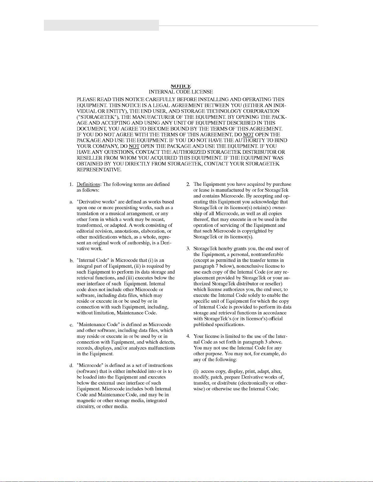
■ Internal Code License
The following is the internal code license from StorageTek:
xx
Page 23

About This Guide
xxi
Page 24

About This Guide
This page intentionally left blank.
xxii
Page 25

General Information
This chapter describes the hardware components of the A4845A Library Storage
Module (LSM). For LSM management software information and drive
information, refer to the publications that pertain to these specific topics.
The LSM is the hardware component in an automated cartridge system. An
automated cartridge system is a removable media, robotic system that mounts
cartridges into a storage cell or into a drive for read/write operations. Figure 1-1
and Figure 1-2 show the major components of an LSM, described in the
following pages.
■ Library Storage Module Components
The LSM has four major, internal components:
• A robot
• Storage cells for 224 to 588 cartridges
• A cartridge access port (CAP) that holds up to 14 cartridges
• Drives
1
Robot
The robot moves cartridges between storage cells and drives when the LSM
management software makes a request to move cartridges. The robot consists
mainly of the Z column assembly and the hand. Figure 1-2 shows the robot
components.
The Z column assembly contains a Z column and Z carriage. The Z column
attaches to the floor and ceiling of the LSM. The Z column rotates almost 360
degrees to allow access to all the cells in the LSM.
The hand mounts to the Z carriage. The Z carriage moves the hand vertically up
and down the Z column to storage cells, drives, or the CAP.
A camera located on the hand reads the cartridge volume serial numbers
(VOLSERs) during audits, but is not used to locate cartridges during robotic
moves. The camera does not read the VOLSERs of cartridges in the drives. If
you manually replace a cartridge in a drive, the host memory will retain the
previous VOLSER. You must request a host update using the LSM management
software to add the information to the host memory.
1-1
Page 26

Library Storage Module Components
Figure 1-1. LSM Major External Components
OPERATOR
PANEL
CARTRIDGE
ACCESS
PORT
(CAP)
DOOR
LATCHES
EXPANSION
DOOR
(OPTIONAL)
RIGHT
FRONT
DOOR
POWER
SWITCH
LOCATION
An audit occurs when:
• You power on the LSM.
• You open and close an LSM door.
• You perform an initial program load (IPL) on the LSM.
• You make a request using the LSM management software.
DRIVES
(INSIDE
LSM)
H_C60022
1-2
Page 27

Figure 1-2. Robot Components
CAMERA
HAND
Library Storage Module Components
Z MOTOR
THETA
MOTOR
Z CARRIAGE
Z COLUMN
H_C60183
1-3
Page 28

Library Storage Module Components
Storage Cells
The LSM is configured by panel, column, row, and cell, so that the LSM
management software can locate a cartridge. The LSM contains storage cells for
224 to 588 cartridges, excluding the CAP cells. The number of cells is
determined by the number of drives installed and whether the LSM has the
standard left front door or the expansion door. The expansion door provides
additional storage space for 168 cartridges. Arrays can be installed above the
drives if fewer than 10 drives are installed.
Cartridges are stored in cell arrays that hold 14 cartridges. The cell arrays are
stacked in columns and the columns are arranged in a circle around the robot
assembly. Each column can hold 42 cartridges.
Table 1-1 lists LSM storage cell capacities. Figure 1-3 and Figure 1-4 show cell
locations for an LSM with the base unit, expansion door, and maximum number
of drives installed.
Note: The two cells located next to drive 4 are designated cleaning cartridge
cells if you have the AUTO CLEAN feature enabled. as described in
“AUTO CLEAN Feature” at the end of this chapter. If you do not, you
must leave those cells empty. You can use the View Config section of
Figure 2-4 in Chapter 2 to determine whether the feature is enabled.
The array targets are used for robotic calibration during IPL.
The drive and CAP locations are not used to store cartridges.
If the LSM loses power while the hand contains a cartridge, the hand
will place the cartridge into the empty/dropoff cell.
Table 1-1. LSM Capacity
Expansion
Door, Panel 3
Yes 0,1,2,3 1 to 3 2 588
No 0,1,2 1 to 3 2 420
Panels
Available
1,2 1 to 3 2 252
Drives
Installed
4 to 6 1 574
7 to 10 0 560
4 to 6 1 406
7 to 10 0 392
4 to 6 1 238
7 to 10 0 224
14-Pack Arrays
above drives
Total
Cartridges
1-4
Page 29
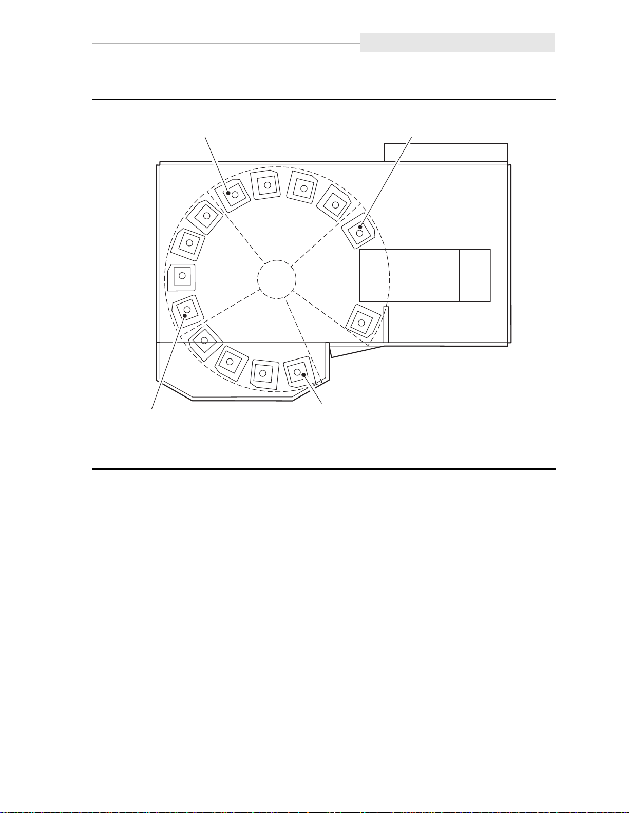
Figure 1-3. Locating Cartridges—Top View
Library Storage Module Components
COLUMN 0
COLUMN 0
PANEL 0
COLUMN 0
PANEL 1
PANEL 2
PANEL 3
COLUMN 0
LSM WITH EXPANSION DOOR
H_C60035
1-5
Page 30

Library Storage Module Components
Figure 1-4. Locating Cartridge-Panels, Columns, Cells, Rows
PANEL 2
COLUMNS
PANEL 1
COLUMNS
0
2
1
DRIVE 9
0
00
3
2
00
1
0
0
0
3
T
DRIVE 8
13
DRIVE 7
CAP
FOR
AREA
RESERVED
DRIVE 6
LATCH
ASSEMBLY
DRIVE 5
23
DRIVE 4
T
DRIVE 3
DRIVE 2
T
DRIVE 1
41
DRIVE 0
41 41
41 41
41
41
14
ARRAY TARGET
(USED FOR
T =
56 CELLS
42 42
42
168 CELLS
42
NOT A STORAGE CELL
CLEANING CARTRIDGE CELL
42
42
H_C60148
ROBOTIC
CALIBRATION)
EMPTY/DROPOFF CELL
DIAGNOSTIC CARTRIDGE CELL
CAP CELLS
2
PANEL 0
COLUMNS
1
0
3
2
PANEL 3
COLUMNS
1
(EXPANSION)
0
000
0
000
TTTT TTTTTTT T
T
TTTTTTTTTTTT T
TTTTTTTTTTTT T
42
168 CELLS
42
41 41 41
42
14 560
41
CAP TOTAL
42
41
42
EXPANSION
4141
42
42
168 CELLS
392 168
BASEDRIVES
CUSTOMER CARTRIDGE CAPACITY CHART
10
1-6
Page 31

Cartridge Access Port
A CAP is the location where you add cartridges to or remove cartridges from an
LSM without interrupting normal cartridge mounts and dismounts by the robot
assembly. The CAP is located on the right front door.
The CAP array can remain in place so that you can insert cartridges into or
remove cartridges from the individual cells. Or, you can remove the top screw
from the array, lift the array out, load all the cells, and slide the array back into
the CAP.
For detailed procedures, refer to “Entering Cartridges through the CAP” and
“Operating the LSM” in Chapter 3, “Operating the LSM.”
Drives
The cartridge is placed into the drive for data read or write operations. The
A4845A can contain three types of drives: DLT4000, DLT7000 and 9840.
Multiple drive types are not allowed in a single library.
The maximum number of drives is ten. The drives are numbered 0 to 9, with 0
at the bottom.
LSM Safety Features
Note: Some software might number the drives from 1 to 10.
For specific drive information, refer to your drive publications.
■ LSM Safety Features
Safety features are incorporated into the LSM. If the front doors to the LSM are
opened, electrical interlocks remove power from the robot assembly.
Behind the right front door, covers are placed over the card and the power
distribution units (PDUs) to prevent you from coming into contact with the
hazardous voltages and sensitive electronics.
■ Controlling Software
Controlling software, within the customer server, requests tape read/write
operations to the drives and robotic move operations for the LSM robotic
components. The software determines where the cartridge is located by
tracking the VOLSER and cell location during audits, then allocates which drive
receives the cartridge. For specific information, refer to your software
publications.
1-7
Page 32

Library Operating Modes
■ Library Operating Modes
An operating mode is the way in which an LSM and the controlling software
(also referred to as the LSM management software) interact. An LSM can operate
in either automated mode or manual mode, as described in the subsections
below.
Automated Mode
Automated mode is the normal operating mode of the LSM. The controlling
software instructs the robot to move the cartridge among the storage cells,
drives, and CAP. The operator tasks include:
• Monitoring the LSM operator display for messages
• Entering a cartridge through the CAP
• Ejecting a cartridge through the CAP
• Replacing a cleaning cartridge
Refer to Chapter 3 for the procedures.
Manual Mode
Manual mode occurs when the LSM right front door is opened to allow operator
intervention. The operator tasks include:
• Moving the robot
• Locating a cartridge
• Removing a cartridge from the hand
• Mounting a cartridge into a drive
• Dismounting a cartridge from a drive
• Returning the LSM to automated mode
Refer to Chapter 3 for the procedures.
■ AUTO CLEAN Feature
Drives might occasionally need to be cleaned to prevent read/write errors.
When your LSM is configured during installation, the AUTO CLEAN feature can
be enabled. You can use the View Config section of Figure 2-4 in Chapter 2 to
determine whether the feature is enabled. If it is, then when a drive needs
cleaning, the robot will receive a software message telling it to retrieve the
cleaning cartridge from the cleaning cartridge cell in the LSM and place it into
the drive.
If AUTO CLEAN is not enabled, you must periodically look at the lights on the
drive. When the Use Cleaning Cartridge light is on, you must place a cleaning
cartridge into the drive.
1-8
Page 33

AUTO CLEAN Feature
Refer to “Setting Cleaning Cartridge Count” in Chapter 2 and “Replacing the
Cleaning Cartridge” in Chapter 3 for more information and procedures.
1-9
Page 34

AUTO CLEAN Feature
This page intentionally left blank.
1-10
Page 35

Controls, Indicators, and Configuration
This chapter shows the locations and describes the functions of the library
storage module (LSM) operator panel and the power switch. It also shows how
to set the Small Computer Systems Interface (SCSI) address and the maximum
usage count of the cleaning cartridges. Refer to the drive publications for
information about operating the drives.
■ LSM Operator Panel
The LSM operator panel is on the right front door of the LSM. The panel
contains softkeys and indicators, plus a two-line display. The LSM operator
panel shows LSM status, configuration, test sequences, and error information.
Figure 2-1 shows the panel and describes each item.
You use this panel to:
• Resolve machine problems.
If an error occurs, the display shows a fault symptom code (FSC) that you
can give to the customer engineer to help resolve problems. Write down the
FSC as soon as it is displayed.
2
• Receive instructions to close the door or cartridge access port (CAP).
• Set the SCSI robotic address.
• Set the maximum usage count of the cleaning cartridge.
2-1
Page 36

LSM Operator Panel
Figure 2-1. LSM Operator Panel Softkeys, Indicators, and Display
2-2
Page 37

■ Setting the SCSI Address
You set the SCSI robotic address from the LSM operator panel. You might need
to get the address from your systems administrator.
Refer to Figure 2-2 and Figure 2-3 to set the SCSI address.
Note: You cannot set the SCSI drive addresses from the LSM operator panel.
For DLT drives, your customer representative uses the switches on the
drive to set the SCSI drive addresses, as described in the installation
manual. For 9840 drives, SCSI drive addresses are set through the drive’s
front panel. This can only be done by a certified Customer Service
Engineer.
CAUTION:
During this procedure, the panel displays “Press Execute to Enter Lib
Size.” This is not normally an operator function. Altering the library size
can cause initialization errors or damage the hand if the size is set
incorrectly to full size when the library has a standar d door i nstead of an
expansion door. Instead of pressing Execute, press Menu.
Setting the SCSI Address
2-3
Page 38

Setting the SCSI Address
Figure 2-2. Symbol Definitions for Menu Block Diagram
Symbol Definitions for Menu Block Diagrams
= display screen with actual display screen text from a top level menu
= display screen with actual display screen text
Test Screens
a bullet ( ) plus
a number and a
multiplication symbol
(Example: 3X)
PATH
INDICATORS
= display screen and type of information screen is displaying
= operator panel softkey operations used in menu sequences
= repeat previous menu actionbullet ( )
= the number of times a previous menu action is repeated
between the first and last option in a sequential menu set
How Used
This configuration
indicates a display
screen and its
softkey options.
H_C60169
2-4
Page 39

Setting the SCSI Address
Refer to Figure 2-2 to make sure that you understand how to read the block
diagrams. Usually, pressing Execute means “yes,” that you want to perform the
activity in the block, and pressing Menu means “no,” that you want to continue
through the choices until your activity appears in the block. Usually, when you
are at the end of the activity, you press Execute. Press Menu if you make a
mistake and need to go through the choices again.
2-5
Page 40

Setting the SCSI Address
Figure 2-3. Setting the SCSI Address
2-6
Page 41

■ Setting Cleaning Cartridge Count
Drives might occasionally need to be cleaned to prevent read/write errors. The
drives are cleaned with a special cleaning cartridge. After a specified number of
uses, the cartridge must be replaced.
If your LSM was configured during installation to have the AUTO CLEAN feature
enabled, you can use the LSM operator panel to set the maximum number of
times a cartridge can be used. You can use the View Config section of
Figure 2-4 in Chapter 2 to determine whether the feature is enabled. The DLT
Tape Drive Product Manual suggest that you use a DLT cleaning cartridge about
20 times. For 9840 linear serpentine cartridges, refer to the 9840 Tape Drive
User’s Reference Manual PN 95739.
Refer to Figure 2-2 and Figure 2-4 to set the count.
Setting Cleaning Cartridge Count
2-7
Page 42

Setting Cleaning Cartridge Count
Figure 2-4. Setting the Cleaning Cartridge Count
Online Cap
Unlk Disabld
MENU
PRESSED
Press Execute to
Run Diagnostics
MENU
PRESSED
Press Execute to
Examine FSC's
MENU
PRESSED
Press Execute to
View Config
MENU
PRESSED
Press Execute to
Replace Cln Cart
MENU
PRESSED
Press Execute to
See/Chg Cln Data
EXECUTE
PRESSED
Press Execute to
*
Show 9840 Data
EXECUTE
PRESSED
MENU
PRESSED
Press Execute to
Exit Menu
EXECUTE
PRESSED
MENU
PRESSED
9840 Limit = XXX
*
Count = XXX
Press Execute to
Change Limit
EXECUTE
PRESSED
Press Execute to
*
EXECUTE
PRESSED
PRESSED
Set to 100
PRESSED
Press Execute to
Set to 1
EXECUTE
PRESSED
PRESSED
Online - Press
Exe to Unlk CAP
MENU
MENU
19X
MENU
If the LSM is configured for DLTs, the DLT screen option will appear instead of
*
9840.
9840 limits decrease from 100 to 1 in decrements of 5; DLT from 20 to 1 in
*
decrements of 1.
H_C60287
2-8
Page 43

■ Power Switch
The power switch is a circuit breaker located in the lower right corner of the
right front door of the LSM.
Lift the switch to supply power to the robot and the drives.
Make sure that all jobs being performed by the drives and robot are complete,
then push down on the switch to remove power to the drives and the robot.
Figure 2-5 shows the power switch location.
Figure 2-5. Power Switch Location
Power Switch
A
POWER
SWITCH
DETAIL A
H_C60155
2-9
Page 44

Power Switch
This page intentionally left blank.
2-10
Page 45

Operating the LSM
This chapter contains the procedures for:
• Powering on the LSM
• Powering off the LSM
• IPLing the LSM
• Operating in automated mode
• Operating in manual mode
Note: When the LSM is controlled by the host, refer to your software
publications and enter the command using the LSM management
software to perform the desired activity. For some activities, you might
have to ask your systems administrator for the required information
■ Powering On or IPLing the LSM
CAUTION:
To prevent damage to the drive, make sure that each drive is empty and
each DLT handle is up. On DLT4000 model drives, you can see whether
the handle is down. On DLT7000 model drives, look for the white hub. If
the hub is up, the handle is down. Figure 3-1 shows the handle
positions.
3
If the handle is down and the Operate Handle indicator is on, push the
shuttle all the way back, pause, then release. The handle will rise. If the
indicator is not on, contact your customer engineer for assistance.
The above caution does not apply to the 9840 tape drives. The 9840
drives do not have a handle.
To power on the LSM, lift the power switch on the bottom right corner of the
right front door of the LSM.
To IPL the LSM, press the IPL softkey on the LSM operator panel.
3-1
Page 46

Powering On or IPLing the LSM
Figure 3-1. DLT Handle Position
A,B
DRIVE
SHUTTLE
CARTRIDGE
HOOK (UP)
DRIVE
HUB
(UP)
HANDLE HANDLE
VIEW A
HANDLE DOWN POSITION
OPERATE
HANDLE
INDICATOR
CARTRIDGE
HOOK (DOWN)
HANDLE UP POSITION
VIEW B
HUB
(DOWN)
UNLOAD
BUTTON
H_E60438
3-2
Page 47

■ Powering Off the LSM
To power off the LSM:
1. Make sure that no jobs are being run by the drives or robot and that no
tapes are in the drives.
2. Push down the power switch on the bottom right corner of the right front
door of the LSM.
■ Operating in Automated Mode
Automated mode is the normal operating mode of the LSM. When the LSM is
online and the robot is mounting and dismounting cartridges, monitor the LSM
operator panel for messages and respond appropriately. The normal message is
“ONLINE CAP UNLK DISABLD” or “ONLINE - PRESS EXE TO UNLK CAP.”
When an LSM is online, you might need to:
• Enter cartridges into the LSM through the cartridge access port (CAP)
• Eject cartridges from the LSM through the CAP
• Replace the cleaning cartridge
The following text describes how to perform these activities.
Powering Off the LSM
Entering Cartridges through the CAP
If the LSM operator panel displays “ONLINE CAP UNLK DISABLD,” the CAP is
locked by the host. Issue the command using the LSM management software
that puts the LSM in the “ONLINE - PRESS EXE TO UNLK CAP” mode. Then
perform the steps below.
To unlock the CAP so that you can open the CAP and enter cartridges into it:
1. Press EXECUTE on the LSM operator panel.
a. The LSM operator panel displays “ONLINE CAP UNLK PENDING.”
b. The hand unlocks the CAP.
c. The LSM operator panel displays “ONLINE CAP UNLOCKED.”
CAUTION:
You must enter the cartridges properly or you might damage the robot or
the drive, or cause the LSM to stop operating. Use only DLT cartridges
for the DLT drives. Use only 9840 cartridges for 9840 drives.
2. Open the CAP to gain access to the cells.
3. Enter the cartridges so that they lie flat, with the customer label on top and
the tape leader block cutout on the right side of the cartridge.
3-3
Page 48

Operating in Automated Mode
CAUTION:
Do not slam the CAP. Cartridges could become unseated and be
extended out into the path of the r obotics , causing se vere dama ge to the
robot hand.
4. Close the CAP. The lock automatically engages.
Note: The LSM management software determines what happens when you
enter a cartridge upside down or with an unreadable label. Under
normal conditions, the camera on the hand audits the CAP and
recognizes that a cartridge is present, but the hand does not move it.
You must remove the cartridge from the CAP. With some host software,
the LSM might stop operating. With other host software, you are
prompted to type a label number when no VOLSER is read. If you do
type a label number, you might cause a problem later during an audit,
because the camera still will not be able to read an unreadable VOLSER
on the cartridge.
Figure 3-2. Entering DLT or 9840 Cartridges through the Cartridge Access Port
3-4
Page 49

Ejecting Cartridges through the CAP
When you want the robot to eject cartridges from the LSM through the CAP, use
the LSM management software to enter the
of the cartridges you require. The robot will retrieve them and place them into
the CAP.
If the LSM operator panel displays “ONLINE CAP UNLK DISABLD,” the CAP is
locked by the LSM management software. Issue the command using the LSM
management software that puts the LSM in the “ONLINE - PRESS EXE TO UNLK
CAP” mode. Then perform the steps below.
To unlock the CAP so that you can open the CAP and remove cartridges from it:
1. Press EXECUTE on the LSM operator panel.
a. The LSM operator panel displays “ONLINE CAP UNLK PENDING.”
b. The hand unlocks the CAP.
c. The LSM operator panel displays “ONLINE CAP UNLOCKED.”
Operating in Automated Mode
2. Open the CAP to gain access to the cells.
3. Remove the cartridges or the array from the CAP.
4. Properly store the cartridges outside the LSM (refer to “Storing Cartridges” in
Chapter 4).
CAUTION:
Do not slam the CAP. Cartridges could become unseated and extend out
into the path of the robotics, causing severe damage to the robot hand.
5. Close the CAP. The lock automatically engages.
6. Repeat these steps until all the desired cartridges have been removed.
Replacing the Cleaning Cartridge
The following paragraphs pertain to an LSM that has the AUTO CLEAN feature
enabled. You can use the View Config section of Figure 2-4 to determine
whether the feature is enabled.
If the feature is not enabled, you will need to record the number of times a
cleaning cartridge has been used, and replace it when necessary.
When a cleaning cartridge has been used a number of times, as defined in
“Setting Cleaning Cartridge Count” in Chapter 2, the LSM operator panel
displays “CLEANING CARTRIDGE USED UP.” If your machine has AUTO
CLEAN enabled, use the procedures in the following sections to replace the
cartridge.
3-5
Page 50

Operating in Automated Mode
Note: The DLT Tape Drive Product Manual recommends using a cleaning
cartridge about 20 times. The 9840 Tape Drive User’s Reference Manual
recommends using the cleaning cartridge 100 times.
Cleaning cartridges have a unique 3-character alphanumeric prefix in their
VOLSER (default is “CLN”). Cleaning cartridges cannot be used as scratch
cartridges or initialized by software utilities.
Note: Make sure that the CAP has an empty cell so that the hand can place the
cartridge into it.
Replacing the Expired Cleaning Cartridge
To replace the expired cleaning cartridge:
1. Press MENU until the LSM operator panel displays “PRESS EXECUTE TO
REPLACE CLN CART.”
2. To replace the DLT cleaning cartridge, press MENU.
The LSM operator panel displays “PRESS EXECUTE TO REPLACE DLT
CART.”
Press EXECUTE and wait until the CAP unlocks.
a. The hand takes the expired cleaning cartridge from its cell inside the
LSM and inserts it into the CAP.
b. The hand unlocks the CAP.
c. Go to Step 4.
3. To replace the 9840 cleaning cartridge, press MENU.
The LSM operator panel displays “PRESS EXECUTE TO REPLACE 9840
CART.”
Press EXECUTE and wait until the CAP unlocks.
a. The hand takes the expired cleaning cartridge from its cell inside the
LSM and inserts it into the CAP.
b. The hand unlocks the CAP.
c. Go to Step 4.
4. Open the CAP and remove the expired cartridge.
5. Throw away the expired cartridge.
CAUTION:
Do not re-enter a cleaning cartridge that has been ejected from an LSM.
When you enter a cleaning cartridge, the software consider s it to be ne w
and sets the usage counter to zero.
3-6
Page 51

6. Insert one new cleaning cartridge into a CAP cell.
CAUTION:
Do not slam the CAP. Cartridges could become unseated and be
extended out into the path of the r obotics , causing se vere dama ge to the
robot hand.
7. Close the CAP. The lock automatically engages.
a. The robot performs a brief audit.
b. The operator panel displays “MOVING CLEANING CART TO CELL.”
c. The hand inserts the cartridge into its cell.
d. The operator panel displays “ONLINE CAP UNLK DISABLD” or
“ONLINE – PRESS EXE TO UNLK CAP.”
■ Operating in Manual Mode
The following text describes operations you can perform when the LSM is in
manual mode. Manual mode occurs when the LSM right front door is opened or
the LSM loses power.
Operating in Manual Mode
Opening the LSM Front Doors
You must open the right front door, then the left front door to perform manual
operations. Refer to Figure 3-3.
1. Make sure that all jobs have ended.
2. Open the LSM right front door by using a latch key to unlock the top and
bottom latches. Turn the key counterclockwise.
3. Open the LSM left front door. For the standard door, pull gently from the
top right corner. For the expansion door, pull from the recessed area on the
right side.
3-7
Page 52

Operating in Manual Mode
Figure 3-3. Opening Access Doors
TOP
LATCH
LATCH
KEY
TOP
LATCH
BOTTOM
LATCH
LSM WITH STANDARD DOOR
LSM WITH EXPANSION DOOR
H_C60032
3-8
Page 53

Moving the Robot
After you open the LSM doors, you might need to move the robot to make it
easier to access the stored cartridges or the drives.
Read and observe the following caution before you attempt to move any
portion of the robot.
CAUTION:
To prevent damaging the hand or Z carriage, make sure that the reach
mechanism on the hand is fully retracted before moving any part of the
robot. Turn the hand pulley to retract the reach mec hanism (refer to
Figure 3-9). If the LSM goes offline due to a power failure, the reach
mechanism might be extended in to a storage cell or drive. If the r obot is
rotated when this condition exists, the hand will be damaged.
Move the Z column and Z carriage only as shown in Figure 3-4 and
Figure 3-5.
Do not touch exposed electrical parts when moving any part of the robot.
Operating in Manual Mode
3-9
Page 54

Operating in Manual Mode
Raising and Lowering the Z Carriage
If you need to raise or lower the hand, slowly and carefully move it by placing
your fingers on the Z carriage as shown in Figure 3-4.
Figure 3-4. Raising and Lowering the Z Carriage
RAISING THE Z CARRIAGE
LOWERING THE Z CARRIAGE
H_E60033
3-10
Page 55

Rotating the Z Column
If you need to rotate the Z column, grasp it and carefully rotate it, as shown in
Figure 3-5.
The Z column does not rotate the full 360 degrees. If the Z column meets
resistance and stops before the desired position is reached, it has contacted a
stopping mechanism. Do not force it. Rotate the column in the opposite
direction.
Figure 3-5. Rotating the Z Column
Operating in Manual Mode
H_E60034
3-11
Page 56

Operating in Manual Mode
Locating a Cartridge in the Storage Cells
Figure 3-6 and Figure 3-7 show the locations of the panels, rows, and columns
of the cartridge storage cells when the expansion door and 10 drives are
installed. The decal at the top of each column also provides location
information.
Figure 3-8 shows the locations of reserved storage cells. These cells are used to
store diagnostic and cleaning cartridges, and to provide an empty/dropoff cell
where the robot inserts a cartridge when the LSM loses power while a cartridge
is in the hand.
CAUTION:
Do not insert data cartridges into reserved cells or the LSM will not be
able to complete its initialization routines. If it does not initialize, it
cannot be placed online.
Figure 3-6. Locating Cartridges—Top View
COLUMN 0
COLUMN 0
PANEL 0
COLUMN 0
PANEL 1
PANEL 2
PANEL 3
COLUMN 0
LSM WITH EXPANSION DOOR
H_C60035
3-12
Page 57

Figure 3-7. Locating Cartridges—Panels, Cells, Rows, Cells
Operating in Manual Mode
PANEL 2
COLUMNS
PANEL 1
COLUMNS
0
2
1
DRIVE 9
0
00
3
2
00
1
0
0
0
3
T
DRIVE 8
13
DRIVE 7
FOR
AREA
RESERVED
DRIVE 6
CAP
LATCH
ASSEMBLY
DRIVE 5
23
DRIVE 4
T
DRIVE 3
T
DRIVE 2
DRIVE 1
41
DRIVE 0
41 41
41 41
41
41
14
ARRAY TARGET
(USED FOR
T =
56 CELLS
42 42
42
168 CELLS
42
NOT A STORAGE CELL
CLEANING CARTRIDGE CELL
42
42
H_C60148
ROBOTIC
CALIBRATION)
EMPTY/DROPOFF CELL
DIAGNOSTIC CARTRIDGE CELL
CAP CELLS
2
PANEL 0
COLUMNS
1
0
3
2
PANEL 3
COLUMNS
1
(EXPANSION)
0
000
0
000
TTTT TTTTTTT T
T
TTTTTTTTTTTT T
TTTTTTTTTTTT T
42
168 CELLS
42
41 41 41
42
14 560
41
CAP TOTAL
42
41
42
EXPANSION
4141
42
42
168 CELLS
392 168
BASEDRIVES
CUSTOMER CARTRIDGE CAPACITY CHART
10
3-13
Page 58

Operating in Manual Mode
Figure 3-8. Diagnostic and Cleaning Cartridge Cell Locations
Removing a Cartridge from the Hand
If the LSM experiences a power failure and the empty/dropoff cell is full, a
cartridge might be left in the hand. You can remove it from the hand and
manually mount it into a drive for a read/write operation.
CAUTION:
Follow the proc edures described in “Movi ng the Robot” above. Faili ng to
do so could damage the hand.
Make sure that you do not touch the TWH card on the hand assembly. It
contains ESD-sensitive components and could be damaged.
To remove a cartridge from the hand:
1. Rotate the Z column:
• If the LSM has an expansion door, move the hand until it is facing the
expansion door location.
• If the LSM has a standard door, move the hand until it is on the left, top
side of the LSM (Panel 0 Column 0).
3-14
Page 59

2. Rotate the hand pulley (refer to Figure 3-9) until the gripper mechanism is
extended to its full position (refer to Figure 3-10).
Figure 3-9. Extending the Gripper Mechanism
TAPE
CARTRIDGE
(SHOWN
RETRACTED)
TWH
CARD
Operating in Manual Mode
HAND
PULLEY
H_C60037
3. Hold the hand pulley with one hand and grasp the cartridge with the other.
Pull gently on the cartridge until it is released from the gripper mechanism,
as shown in Figure 3-10.
4. Turn the hand pulley until the gripper mechanism is fully retracted.
CAUTION:
Make sure that the gripper mechanism is full y retracted. If it is left
extended and you turn the robot, the gripper mechanism will strike a
storage cell. If it is left extended and the hand is f acing the LSM door
when it is closed, the door will strike the gripper mec hanism.
3-15
Page 60

Operating in Manual Mode
Figure 3-10. Removing a Cartridge from the Hand
REACH
MECHANISM
(SHOWN
EXTENDED)
GRIPPER
MECHANISM
TAPE
CARTRIDGE
TWH
CARD
HAND
PULLEY
H_C60036
3-16
Page 61

Mounting a DLT Cartridge into a Drive
CAUTION:
Before you mount a cartridge into the drive, you must make sure that
power is on, and that the Operate Handle indicator is on. Use the drive
shuttle to operate, not the drive handle.
A safety mechanism protects the drive if y ou try to operate it in an
incorrect state. The shuttle will not operate if this mechani sm is
activated. To reset the safety mechanism, wait for the Operate Handle
indicator to turn on. Pull firmly on the shuttle, then push the shuttle in
completely. If the cartridge did not eject, or if the handle di d not ri se, pull
and push again.
To mount a cartridge into a drive:
1. Obtain the cartridge VOLSER, location, and drive number using the LSM
management software.
2. Open the LSM right front door by using a latch key to unlock the top and
bottom latches. Refer to Figure 3-3.
Operating in Manual Mode
3. Open the LSM left front door. For the standard door, pull gently from the
top right corner. For the expansion door, pull from the recessed area on the
right side.
4. Locate the cartridge.
5. Make sure that the DLT handle is up and the cartridge handle hook and hub
are down. Figure 3-11 shows the handle positions.
CAUTION:
You must insert the cartridge properly or you will damage the drive.
Make sure that the cartridge has a readable V O LSER.
6. Hold the cartridge so that the VOLSER is facing you and the write-protect
switch is on the right side of the cartridge. Refer to Figure 3-13.
7. Insert the cartridge into the shuttle and push the cartridge into the back of
the drive until it is firmly seated.
8. Push the shuttle all the way back, pause for about two seconds, then release
the shuttle.
CAUTION:
If the cartridge has been ejected from the dri ve, y ou must remove it from
the shuttle before you can reload it into the drive. Otherwise, the shuttle
will become jammed by simultaneously holding onto the cartridge and
lowering the handle. If this happens, release the cartridge from the
shuttle latch under the right side of the cartridge. Then push the
cartridge into the drive and lower the handle.
3-17
Page 62

Operating in Manual Mode
Figure 3-11. DLT Handle Position
A,B
DRIVE
SHUTTLE
CARTRIDGE
HOOK (UP)
DRIVE
HUB
(UP)
HANDLE HANDLE
VIEW A
HANDLE DOWN POSITION
OPERATE
HANDLE
INDICATOR
CARTRIDGE
HOOK (DOWN)
HANDLE UP POSITION
VIEW B
HUB
(DOWN)
UNLOAD
BUTTON
H_E60438
3-18
Page 63

Figure 3-12. Inserting a DLT Cartridge into a Drive
DRIVE
Operating in Manual Mode
CARTRIDGE
H_E60374
3-19
Page 64

Operating in Manual Mode
Mounting a Cartridge into a 9840 Drive
To mount the cartridge in a 9840 drive:
1. Insert the cartridge into the 9840 drive using the direction shown in
Figure 3-13.
2. Wait for one of the following messages to display and take the appropriate
action, if necessary:
• The “Ready F” (File Protected) message displays when a write-protected
cartridge loads successfully.
• The “Ready U” (File Unprotected) message displays when a cartridge
that is not write-protected loads successfully.
• The “NTReady” message displays when the tape in the cartridge has lost
tension. If this occurs call your Customer Support Engineer
• The LOADxxxx” message displays when the cartridge unsuccessfully
loads, where the xxxx is a fault symptom code. If this occurs call your
Customer Support Engineer.
3-20
Page 65

Figure 3-13. Mounting a Cartridge into the 9840 Drive
Operating in Manual Mode
Dismounting a Cartridge from a DLT Drive
To dismount a cartridge from a drive:
1. Obtain the drive number using the LSM management software and place the
drive offline.
2. Open the LSM right front door by using a latch key to unlock the top and
bottom latches. Refer to Figure 3-3.
3. Open the LSM left front door. For the standard door, pull gently from the
top right corner. For the expansion door, pull from the recessed area on the
right side.
4. Locate the desired drive.
5. Make sure that the job is done.
6. Make sure that the Operate Handle indicator is on. If it is not, press the
Unload button on the drive to unload the drive. The indicator will turn on.
7. Push the shuttle all the way back, pause for about two seconds, then release
the shuttle.
3-21
Page 66

Operating in Manual Mode
Note: If the cartridge does not come out of the drive, remount the cartridge
by releasing it from the shuttle latch under the right side of the
cartridge. Then push the cartridge into the drive and lower the
handle. If this fails, the tape leader might be dislodged and require
rethreading.
8. Remove the cartridge from the drive.
9. Properly store the cartridge outside the LSM (refer to “Storing Cartridges” in
Chapter 4).
Dismounting a Cartridge from a 9840 Drive
To dismount a cartridge from a 9840 drive:
1. Ensure that the 9840 drive is not selected form the host.
2. Press the Unload switch.
3. After the tape rewinds, the cartridge ejects from the 9840 drive. Remove the
cartridge form the 9840 drive.
Returning the LSM to Online Status
To place the LSM online for automated operations:
1. Make sure that the drive shuttle Operate Handle indicator is on and the
handle is up.
2. Close and lock the LSM doors. The robot will perform an audit of the cells.
3-22
Page 67

Cartridges
The chapter describes how to prepare and maintain cartridges.
■ Preparing Cartridges
The following pages describe how to prepare a cartridge for use in the LSM.
Handling a Cartridge
Generally observe the following protocols when handling cartridges:
• Keep cartridges clean.
• Inspect a cartridge before each use.
• Do not put a damaged cartridge into a drive or LSM.
• Do not open a cartridge.
• Do not release a leader block and pull tape from a cartridge.
• Do not handle tape that is outside the cartridge.
• Do not expose the tape or cartridge to direct sunlight or moisture.
• Do not expose a recorded cartridge to magnetic fields.
4
Inspecting a Cartridge
A defective or dirty cartridge can damage a drive. If you suspect a problem with
a cartridge, inspect it for these defects:
• Cracked or broken cartridge
• Broken leader block
• Broken leader block latch
• Damaged write protect switch
• Moisture
• Labels not firmly attached or extending over the cartridge edge
• Any other obvious damage
4-1
Page 68

Preparing Cartridges
Figure 4-1. Inspecting a DLT Cartridge
Figure 4-2. Inspecting a 9840 Cartridge
4-2
Page 69

Applying DLT Cartridge Labels
The LSM uses DLTtape IV or IIIXT cartridges for data, plus diagnostic and
cleaning cartridges. Different types of data cartridges are distinguished by a
small “E” or “D” next to the last number in the VOLSER. Cleaning and
diagnostic cartridges are distinguished by “CLN” or “DG” in the prefix in the
VOLSER. The correct labeling follows:
• DLTtape IV data cartridges should be labeled with a “D” label.
• DLTtape IIIXT data cartridges should be labeled with an “E” label.
• Cleaning cartridges should be labeled with a “CLN” label.
• Diagnostic cartridges should be labeled with a “DG” label.
Note: Diagnostic cartridges are physically the same as data cartridges. The LSM
software requires the “DG” label before it will use a cartridge for
diagnostic routines. One diagnostic cartridge is supplied with the LSM.
The operator is responsible for applying labels correctly as indicated above and
in Figure 4-3. Cartridge surfaces should be clean and at room temperature when
applying labels. Labels can be inserted into the recessed area, or the backing
can be peeled away to expose the adhesive, if a more permanent application is
desired. Do not place labels anywhere but in the recessed VOLSER slot, and
make sure that the edges do not curl up, which might cause misreading or
sticking.
Preparing Cartridges
Figure 4-3. Applying DLT Cartridge Labels
4-3
Page 70

Preparing Cartridges
Applying 9840 Cartridge Labels
Figure 4-4. Applying 9840 Cartridge labels
Cartridge labels reflect the cartridge media and usage. Cleaning cartridges have
DG CLN in the VOLSER and a “U” beneath the VOLSER. Diagnostic cartridges
have DG 000 in the VOLSER and an “R” beneath the VOLSER.
Refer to Figure 4-4 and insert the label into the recessed area provided on each
cartridge.
1. Make sure that the cartridge has been at room temperature for at least 24
hours.
2. Clean the surface where the labels will be placed using a cleaning solution
made for this purpose. Refer to “Cleaning the Cartridge Exterior” for
additional information.
3. Locate the label that you require and refer to Figure 4-4.
Refer to Figure 4-4 and slide the label under the slots in the recessed area. If
you want, peel the backing from the label and then slide it under the slots,
pressing it into place.
Notes:
1. Make sure that the labels are not placed elsewhere on the cartridge surface.
2. Make sure that the edges of the labels do not curl up; curling causes the
cartridge to stick in the drive loader.
4-4
Page 71

3. Use labels that do not leave a residue when removed.
4. Make sure that the label contains a VOLSER.
Preparing Cartridges
4-5
Page 72

Preparing Cartridges
Setting the DLT Write-Protect Switch
Refer to Figure 4-5 to see the location of the write protect switch. To set the
cartridge to write-protected, slide the switch to the left so the orange indicator is
visible. In this position, the drive can only read data from the tape and cannot
write data to the tape.
To set the cartridge to write-enabled, slide the switch to the right so the orange
indicator is not visible. In this position, the drive can write as well as read data.
Figure 4-5. Setting the DLT Write-Protect Switch
4-6
Page 73

Setting the 9840 Write-Protect Switch
To write-protect a cartridge, follow these steps:
1. Hold the cartridge with the customer label side up and the rear VOLSER
label toward you. (Refer to Figure 4-6 on page 4-7.)
2. Locate the write-protect switch on the right side of the cartridge.
3. Move the write-protect switch to the front of the cartridge (away from you)
to the write-protect position.
Figure 4-6. Setting the 9840 Write-Protect Switch
Preparing Cartridges
4-7
Page 74

Maintaining Cartridges
■ Maintaining Cartridges
The following sections describe how to store and clean cartridges.
Storing Cartridges
When you store a cartridge:
• Do not take a cartridge out of its protective wrapping until you are ready to
use it.
• Store cartridges in a clean environment that duplicates the conditions of the
room in which they are used.
• Before using a cartridge, make sure that it has been in its operating
environment for at least 24 hours.
Cleaning the Cartridge Exterior
CAUTION:
Do not use certain solvents to remove labels or to clean cartridges
because they can damage the cartridges. Do not use acetone,
trichloroethane, toluene, xylene, benzene, ketone, methylethyl ketone,
methylene chloride, ethyldichloride, esters, ethyl acetate, or similar
chemicals.
Wipe all dust, dirt, and moisture from the cartridge with a lint-free cloth.
4-8
Page 75

Specifications
This appendix lists the supplies and accessories, specifications, and agency
certifications.
■ Supplies and Accessories
Table A-1 lists supplies and accessories:
Table A-1. Supplies and Accessories
A
Item
DLT Tape Cartridges
HP DLTtape IV Data Cartridge
20 GByte/35 Gbyte native
capacity
HP DLTtape III XT Data
Cartridge
15 Gbyte native capacity
Cleaning Tape Cartridge
DLT Bar Code Labels
DLT Bar code labels are not available through Hewlett-Packard, but may be ordered from
Engineered Data Products (EDP). Refer to the following page.
9840 Tape Cartridges and
Bar Code Labels
9840 tape cartridges and labels are not available through Hewlett-Packard, but may be
ordered from the StorageTek Media Department. Refer to Ordering 9840 Tape Cartridge
and Labels.
SCSI Cables (68-pin to 68-pin)
HP Product Number HP Part Number
C5141F Not applicable
C5141A Not appli cabl e
C5142A Not appli cable
0.5m SCSI cable; high-density
with thumb screws to highdensity with thumb screws,
m-m
A-1
C6509A 8120-6147
Page 76

Supplies and Accessories
Table A-1. Supplies and Accessories
2.5m SCSI cable; high-density
with thumb screws to highdensity with thumb screws,
m-m
5.0 SCSI cable; high-density
with thumb screws to highdensity with thumb screws,
m-m
10m SCSI cable; high-density
with thumb screws to highdensity with thumb screws,
m-m
20m SCSI cable; high-density
with thumb screws to highdensity with thumb screws,
m-m
SCSI Cables for V-Class (68-pin to 68-pin)
5.0m SCSI cable; high-density
with thumb screws to highdensity with thumb screws, mm; with inline terminator for
V-Class
C2924A A1658-62020
C6510A A1658-62021
C2925A A1658-62022
C2926A A1658-62023
Not applicable A4801-63004
10m SCSI cable; high-density
with thumb screws to highdensity with thumb screws, mm; with inline terminator for
V-Class
SCSI Cables (50-pin to 68-pin)
1.0m SCSI cable; high-density
with thumb screws to highdensity with thumb screws,
m-m
1.5m SCSI cable; high-density
with thumb screws to highdensity with thumb screws,
m-m
2m SCSI cable; high-density
with thumb screws to highdensity with thumb screws,
m-m
Not applicable A4801-63002
C2961A 5181-7705
C2962A 5181-7706
C2906A 5181-7707
A-2
Page 77

Table A-1. Supplies and Accessories
Ordering DLT Cartridge Labels
5m SCSI cable; high-density
with thumb screws to highdensity with thumb screws,
m-m
SCSI Terminators (68-pin)
Single-ended SCSI Terminator
Wide Differential Terminator
C2907A 5181-7708
C6511A 5063-5324
C2905A A1658-62024
■ Ordering DLT Cartridge Labels
Each LSM is supplied with a sufficient quantity of data cartridge labels (with the
“D” designation) to match a fully populated library (588 cartridges). To order
additional labels, contact Engineered Data Products (EDP) for a reference to a
dealer who services your area.
Engineered Data Products, Inc. (EDP)
2550 West Midway Blvd.
Broomfield, CO 80020
U.S. Sales Line: 1-800-432-1337
Fax: 303-465-4936
Engineered Data Products Europe, Ltd.
43 Redhills Road
South Woodham Ferrers
Chelmsford; Essex CM3 5UL
Phone: (44) 1245-322380
Fax: (44) 1245-323484
Table A-2 lists EDP DLT cartridge label specifications:
Table A-2. EDP DLT Cartridge Label Specifications
Data Cartridge Label Diagnostic Cartridge Label Cleaning Cartridge Label
EDP PN 1703-OD
Bar code 3 of 9
Dimensions: 0.82” x 2.20”
Sold in sets of 200
Customer to specify numeric
sequence
EDP PN 1703-DG
Bar code 3 of 9
Dimensions: 0.82” x 2.20”
Sold in sets of 20
Customer to specify numeric
sequence
EDP PN 1703-CN
Bar code 3 of 9
Dimensions: 0.82” x 2.20”
Sold in sets of 20
Customer to specify numeric
sequence
A-3
Page 78

Ordering 9840 Tape Cartridge and Bar
■ Ordering 9840 Tape Cartridge and Bar Code
Labels
To order 9840 tape cartrdiges and bar code labels, contact StorageTek Media
Department.
Austria: 0800-20-1631
Belgium: 0800-75-327
Denmark 8088-0744
Finland 08001-13361
France 0800-82-83-57
Germany 0800-181-6238
Holland 0800-022-8496
Ireland 1800-55-33-54
Italy 167-790-852
Norway 800-11-220
South America 0800-99-5820
Spain 900-99-33-66
UK 0800-731-8852
US 800-905-8502
Canada 905-602-5586
Asia/Pacific 61-2-9433-1700
Japan 81-3-3746-9711
Latin America 303-661-5398
A-4
Page 79

Basic Requirements for Cartridges
■ Basic Requirements for Cartridges
LSM cartridges must meet specifications defined in, American National
Standard Magnetic Tape & Cartridge for Information Interchange, ACS X3B5.
Cartridges must meet the following requirements:
Table A-3. Basic Requirements for DLT Cartridges
Cartridges 10.16 cm x 12.7 cm x 2.54 cm (4 in. x 5 in. x 1 in.)
Integrated thumbwheel
Media Chromium dioxide
1.27 cm (0.5 in.) wide
165 m (541 ft) long minimum
No beginning of tape/end of tape reflective markers
Volume serial number
(VOLSER) label
Table A-4 shows the specifications for the tape cartridges to be inserted into the
9840 Tape Drive System.
Table A-4. 9840 Cartridge Specifications
Characteristics Values
Cartridge type STK1R
Cartridge type STK1U
Dimensions 125 x 109 x 24.5 mm
Weight 260 g (9.17 oz.)
Data compression LZ-1 Enhanced
Media life 10 year minimum
Data error rates, including those caused by
media defects
Valid characters are A-Z, 0-9, # (crosshatch), or trailing blanks.
Leading blanks are not allowed.
270 m (886 ft) 8 microns tape
Cleaning cartridge
(4.92 x 4.29 x 0.958 in.)
Uncorrected bit error rate (BER) is 1 in 10
bytes
18
A-5
Page 80

Basic Requirements for Cartridges
DLT Cartridge Environmental Specifications
The following specifications refer to the operating and storage environments for
DLT cartridges, according to international standard ECMA-209.
Table A-5. DLT Cartridge Environmental Specifications
Operating environment
Temperature
Relative humidity
Wet bulb temperature
CAUTION:
Tape temperatures above 49ºC (120ºF) might damage the tapes. If during storage or
transportation a cartridge has been exposed to conditions outside th e abo ve val ues,
before using the cartridge, keep the cartridge within those operating environment
specifications for at least as l ong as the time pe riod tha t the cartridge was not within
the specifications, up to two hour s. Make sure that the cartridge has no moisture on
it.
10º to 40ºC (50º to 104ºF)
20% to 80% noncondensing
25ºC (77ºF) maximum
CAUTION:
When storing DLT cartridges, the stray magnetic field at any point on the tape shall
not exceed 4000A/m. Make sure that the cartridge has no moisture on it.
Cartridge storage environment
Temperature
Relative humidity
Wet bulb temperature
Cartridge storage environment for cartridges
intended for archiving data for one year or
more
Temperature
Relative humidity
16º to 32ºC (61º to 90ºF)
20% to 80% noncondensing
26ºC (79ºF) maximum
18º to 26ºC (64º to 79ºF)
20% to 60%
A-6
Page 81

Basic Requirements for Cartridges
9840 Cartridge Environmental Specifications
The following specifications refer to the operating and storage environments for
9840 cartridges.
Table A-6. 9840 Cartridge Environmental Specifications
Operating environment *
Temperature
Relative humidity
Wet bulb temperature
Cartridge storage environment (nonarchive)
Temperature
Relative humidity
Wet bulb temperature
Cartridge storage environment (archive)
Temperature
Relative humidity
Wet bulb temperature
15.6°–32.2° C (60°–90° F)
20%–80%
26° C (78.8° F) maximum
5°–32.2° C (41°–90° F)
5%–80%
26° C (78.8° F) maximum
5°–25.5° C (41°–78° F)
40%–60%
26° C (78.8° F) maximum
Cartridge shipping environment
(unrecorded) *
Temperature
Relative humidity
Wet bulb temperature
Cartridge shipping environment (recorded)
*
Temperature
Relative humidity
Wet bulb temperature
* The conditioning time before use is 24 hours.
** The shipping environment must not exceed the limit of the storage environment, archive
or non-archive, for longer than 10 days.
-23°–49° C (-10°–120° F)
5%–80%
26° C (78.8° F) maximum
4°–40° C (40°–104° F)
5%–80%
26° C (78.8° F) maximum
A-7
Page 82

LSM Specifications
■ LSM Specifications
Table A-7. LSM Dimensions and Weights
Specification Two Drives** Ten Drives
Height 183 cm (72 in.) 183 cm (72 in.)
Width with covers 148 cm (58 in.) 148 cm (58 in.)
Depth with standard door and covers 79 cm (31 in.) 79 cm (31 in.)
Depth with expansion door and
covers
Weight * 370 kg (815 lbs) 455 kg (1003 lbs)
Weight with expansion door * 494 kg (1088 lbs) 579 kg (1276 lbs)
* The weight does not include cartridge weight. Each cartridge weighs
approximately 255 g (9 oz).
**Each 9840 drive weighs 10.7 kg (23.5 lbs).
**Each DLT drive weighs 6.81 kg(15 lbs)
Table A-8. LSM Main Power Distriution Unit Specifications
Power configuration US/Canada 120 VAC
UL/CSA power cable
Europe 200 to 240 VAC
HAR power cable
Input voltage range
Nominal voltage
Input current * US/Canada:
120 or 240 VAC
100 to 254 VAC
Single phase 100 to 120 VAC
47 to 63 Hz
20 A Service
3 wire
102 cm (40 in.) 102 cm (40 in.)
International:
Single phase 200 to 240 VAC
47 to 63 Hz
10 A Service
3 wire
Power consumption * 108 W
Maximum heat output * 368 Btu/hr
* This information applies only to the main PDU.
A-8
Page 83

LSM Specifications
Table A-9. LSM Second Power Distribuition Unit Requirements
Power configuration US/Canada 100 to 120 VAC
UL/CSA power cable
Europe 200 to 240 VAC
HAR power cable
Input voltage rangeNominal
voltage
100 to 120/200 to 240 VAC
120 to 230 VAC
Input current US/Canada:
Single phase 120 VAC
47 to 63 Hz
6 A Service
3 wire
International:
Single phase 200 to 240 VAC
47 to 63 Hz
3 A Service
3 wire
Table A-10. LSM Environmental Limits
Temperature
Operating
Storage
Shipping
Relative Humidity
Operating
Storage
Shipping
15º to 32ºC (59º to 90ºF)
10º to 40ºC (50º to 104ºF)
-40º to 60ºC (-40º to 140ºF)
20% to 80% (noncondensing)
10% to 95% (noncondensing)
10% to 95% (noncondensing)
Wet Bulb Maximum
Operating
Storage
Shipping
29.2ºC (84.5ºF)
35ºC (95ºF)
35ºC (95ºF)
Altitude
Operating
Storage
Shipping
A-9
0 to 3,048 m (0 to 10,000 ft)
0 to 3,048 m (0 to 10,000 ft)
0 to 15,240 m (0 to 50,000 ft)
Page 84

Agency Certifications
■ Agency Certifications
Table A-11. Agency Certifications
Category Certification
Safety CSA standard CAN/CSA-C22.2 no. 950-M93
UL standard 1950, Third Edition
EN60950
Emissions FCC #47, Part 15, Subpart B, Class A
EMC Framework AS/NZS 3598: 1995 (Australia, N.Z.)
VCCI Class A
European Union CE emissions standards
Canadian EMC Law; ICES-003
Korean EMC Law
BCIQ EMC Law CNS 13438 (Taiwan)
Immunity European Union CE immunity standards
AS/NZS 4252.1: 1994 Generic Immunity Standard
A-10
Page 85

Glossary
The following terms are used in this guide
or apply to this product.
Numeric
9840 A device that reads from or writes to
a magnetic tape.
A
audit A part of the LSM’s IPL sequence
that catalogs all cartridge locations within
the LSM cells and retains the data in the
memory.
AUTO CLEAN A feature that enables the
control software to tell the robot when a
drive needs to be cleaned. The robot
retrieves the cleaning cartridge and mounts
it into the drive.
automated mode A relationship between
an LSM and its hosts. In an LSM operating
in automated mode, the robot moves the
cartridges among the storage cells, CAP,
and drives. This is the normal operating
mode of an LSM that is communicating
with the host central processing unit.
preloaded array into the CAP. The CAP is
located on the right front door of the LSM.
cartridge tape Magnetic tape enclosed in
a plastic housing.
catalog The inventory of all cartridge
storage locations in an LSM; this inventory
is by LSM number, panel, row, column.
CE See customer engineer.
cell A slot in the LSM that is used to store
a cartridge.
configuration The description of an LSM,
listing the panel types and drives.
customer engineer (CE) An employee
trained to install, maintain, and repair
equipment.
D
diagnostic programs Tests, accessible
through the LSM operator panel, that allow
a CE to run offline tests within the LSM.
DLT (digital linear tape) drive A device
that reads from or writes to a magnetic
tape.
drive See DLT (digital linear tape) drive.
C
CAP See cartridge access port.
cartridge The plastic housing around the
tape. A plastic leader block is attached to
the tape for automatic threading when
loaded in a drive. The spine of the cartridge
contains a VOLSER label listing the volume
identification number.
cartridge access port An assembly that
allows an operator to enter/eject up to 14
cartridges during automated operations.
The operator can open the CAP and place
each cartridge into the cells or place a
Glossary-1
E
expansion door A door that can be
ordered instead of the standard door that,
when mounted onto the front of the LSM,
provides cells for an additional 168
cartridges.
F
fault symptom code Error or information
code generated by functional or diagnostic
software that may directly or indirectly be
Page 86

Glossary
used to indicate the field replaceable unit
(FRU) that is probably causing the error.
FSC See fault symptom code.
I
ID Identifier or identification.
initial program load A process that
activates a machine reset and loads system
programs to prepare a computer system for
operation. Processors with diagnostic
routines activate these routines at IPL
execution.
IPL See initial program load.
L
library storage module A unit that
contains the storage area for cartridges, the
robot that moves the cartridges, and the
drives.
LSM See library storage module.
M
S
SCSI See Small Computer Systems
Interface.
Small Computer Systems Interface A
data interface between the drives and host.
V
VOLSER See volume serial label.
volume serial label An alphanumeric
label used by LSM management software to
identify a volume. It is attached to the spine
of a cartridge and can be read by people
and the camera.
volume Magnetic cartridge.
W
write protect switch A switch on a
cartridge that can be set to write protected,
so that a drive can only read data from the
tape, or to write enabled, so that a drive
can read data from the tape and write data
to the tape.
manual mode A relationship between an
LSM and its attached host. An LSM
operating in manual mode is not
communicating with the host central
processing unit and requires human
assistance to perform cartridge operations.
O
online State of being controlled directly
by or in direct communication with a
computer. Available for functional use.
R
robot Electromechanical device for
locating and moving cartridges.
Z
Z carriage The assembly that moves the
hand vertically up and down the Z column
to storage cells, drives, and the CAP.
Z column The column which rotates
around the cells within the LSM.
Glossary-2
Page 87

Index
Numerics
9840
cartridge labels 4-4
relative humidity specs A-7
wet bulb maximum A-7
A
A4845A LSM
LSM (library storage module) 1-1
accessories A-1
address, setting
SCSI 2-3
applying cartridge labels
9840 4-4
applying labels 4-3
auto clean 1-8
automated
mode 1-8
operations 3-3
C
CAP (cartridge access port)
described 1-7
ejecting cartridges 3-5
entering cartridges 3-3
location 1-2
capacity of cartridge A-5
cartridge
capacity A-5
data compression A-5
data error rates A-5
dimensions A-5
media life A-5
weight A-5
cartridges
applying labels 4-3
DLT environment A-6
handling 4-1
inspecting 4-1
label
9840 4-4
location
cleaning 3-13
diagnostic 3-13
setting
9840 write-protect switch 4-7
setting write protect switch 4-6
storing 4-8
cell
cleaning cartridge 3-13
diagnostic cartridge 3-13
empty/dropoff 3-13
reserved 3-12
circuit breaker, power 2-9
cleaning cartridge
cell location 3-13
part number A-5
replacing 3-5
setting cartridge count 2-7
controlling software 1-7
customer label
9840 cartridge 4-4
D
data compression of cartridge A-5
data error rates (cartridge) A-5
diagnostic
cartridge cell location 3-13
dimensions of cartridge A-5
DLT (digital linear tape)
cartridge specifications A-6
configuration 1-7
DLT write protect switch 4-6
DLT write-enabled switch 4-6
doors, opening 3-7
drive 1-7
E
ejecting cartridges through CAP 3-5
empty/dropoff cell 3-12
entering cartridges through CAP 3-3
error rates, data (cartridge) A-5
G
gripper mechanism location 3-16, 3-21
grounding xix
Index-1
Page 88

Index
H
hand
description 1-1
location 1-3
removing cartridge manually 3-14
hand pulley location 3-15
I
indicators, LSM operator panel 2-1
initial program load 3-1
IPL procedure 3-1
L
labels
applying 4-3
ordering A-3
labels, applying
9840 4-4
life, media (cartridge) A-5
locating cartridge manually 3-12
locations
camera 1-3
cartridge access port (CAP) 1-2
DLT leader block 4-2
doors 1-2
drives 1-2
gripper mechanism 3-16, 3-21
hand 1-3
hand pulley 3-15
operator panel 1-2
power switch 1-2
switches and indicators 2-1
VOLSER label, 9840 cartridge 4-4
write protect switch 4-6
write-protect switch, 9840 4-7
Z carriage 1-3
Z column 1-3
LSM (library storage module)
CAP 1-7
cartridge storage capacity 1-4
components 1-1
controlling software 1-7
LSM operator panel 2-1
robot 1-1
described 1-1
drives 1-7
modes 1-8
opening doors 3-7
powering off procedure 3-3
powering on procedure 3-1
safety 1-7
specifications A-8
M
manual
mode 1-8
operations 3-7
mode
automated 1-8
manual 1-8
moving robot manually 3-9
O
opening LSM doors 3-7
operations
applying 9840 cartridge labels 4-4
operator panel
location 2-1
setting cleaning cartridge count 2-7
setting SCSI address 2-3
switches and indicators 2-1
ordering DLT labels A-3
P
panel, LSM operator
panel, LSM operator 2-1
power
switch location 2-9
power off procedure 3-3
power on procedure 3-1
R
rates, data error (cartridge) A-5
regulatory statements v
removing cartridge from hand 3-14
replacing cleaning cartridge 3-5
robot
components
hand 1-1
Z column 1-1
Z mechanism 1-1
moving robot manually 3-9
Index-2
Page 89

S
safety 1-7
SCSI
setting robotic address 2-3
service xviii
setting
9840 write-protect switch 4-7
cleaning cartridge count 2-7
SCSI address 2-3
write protect switch 4-6
specifications A-8
DLT cartridge environment A-6
storing cartridges 4-8
supplies A-1
switches
operator panel 2-1
power 2-9
write-enabled, 9840 4-7
write-enabled, DLT 4-6
write-protect, 9840 4-7
write-protect, DLT 4-6
Index
T
Taiwan warning label statement vii
V
VOLSER label
9840 cartridge 4-4
W
warranty xviii
weight
cartridge A-5
Z
Z carriage
location 1-3
moving 3-10
Z column
described 1-1
location 1-3
moving 3-11
Index-3
Page 90

Index
Index-4
Page 91

Reader Comment Sheet
A4845A Library Storage Module: Hardware Operator’s Guide
We welcome your evaluation of this manual. Your comments and suggestions will help us
improve our publications.
Remove this page and mail or FAX it to 916-785-2875. Use and attach additional pages if
necessary.
Agree Disagree N/A
The manual is well organized. ❍❍❍❍❍❍
The information is technically accurate. ❍❍❍❍❍❍
Information is easy to find. ❍❍❍❍❍❍
Step-by-step procedures are easy to perform. ❍❍❍❍❍❍
There are enough examples and pictures. ❍❍❍❍❍❍
The examples and pictures are useful. ❍❍❍❍❍❍
Comment: ________________________________________________________________________
_________________________________________________________________________________
_________________________________________________________________________________
_________________________________________________________________________________
_________________________________________________________________________________
Name: Phone:
Title: Fax:
Company: E-mail:
Address: Zip:
City & State: Country:
___ Check here if you would like a reply.
Hewlett-Packard has the right to use submitted suggestions without obligation, with all such
ideas becoming property of Hewlett-Packard.
ESBU Information Engineering
A4845-96014 E0699
Page 92

TO COMPLY WITH POSTAL REGULATIONS, FOLD EXACTLY ON DOTTED LINES AND TAPE (DO NOT STAPLE)
BUSINESS REPLY CARD
FIRST CLASS MAIL
POSTAGE WILL BE PAID BY ADDRESSEE
Attention: Information Engineering (MS5668)
Hewlett-Packard Company
Enterprise Storage Solutions Division
8000 Foothills Boulevard
Roseville, CA 95747-5668
FOLD HERE AND TAPE FOLD HERE AND TAPEDO NOT STAPLE
PERMIT NO. 256 ROSEVILLE, CA
NO POSTAGE
NECESSARY
IF MAILED
IN THE
UNITED STATES
Page 93

Page 94

 Loading...