

Page 1

HP StorageWorks
Fabric OS 5.x
command reference guide
Part number: AA–RVHVB–TE
Second edition: September 2005
Page 2

Legal and notice information
© Copyright 2005 Hewlett-Packard Development Company, L.P.
© Copyright 2005, Brocade Communications Systems, Incorporated.
Hewlett-Packard Company makes no warranty of any kind with regard to this material, including, but not limited to, the implied warranties of
merchantability and fitness for a particular purpose. Hewlett-Packard shall not be liable for errors contained herein or for incidental or
consequential damages in connection with the furnishing, performance, or use of this material.
This document contains proprietary information, which is protected by copyright. No part of this document may be photocopied, reproduced, or
translated into another language without the prior written consent of Hewlett-Packard. The information is provided “as is” without warranty of any
kind and is subject to change without notice. The only warranties for HP products and services are set forth in the express warranty statements
accompanying such products and services. Nothing herein should be construed as constituting an additional warranty. HP shall not be liable for
technical or editorial errors or omissions contained herein.
Microsoft, Windows and Windows NT are U.S. registered trademarks of Microsoft Corporation.
UNIX is a registered trademark of The Open Group.
Fabric OS 5.x command reference guide
Page 3

Contents
About this guide . . . . . . . . . . . . . . . . . . . . . . . . . . . . . . . . . . . . . . . . . . . . 13
Intended audience . . . . . . . . . . . . . . . . . . . . . . . . . . . . . . . . . . . . . . . . . . . . . . . . . . . . . . . . . . . . . . 13
Related documentation . . . . . . . . . . . . . . . . . . . . . . . . . . . . . . . . . . . . . . . . . . . . . . . . . . . . . . . . . . . 13
HP StorageWorks Fabric OS 5.x master glossary . . . . . . . . . . . . . . . . . . . . . . . . . . . . . . . . . . . . . . . . . 13
Document conventions and symbols . . . . . . . . . . . . . . . . . . . . . . . . . . . . . . . . . . . . . . . . . . . . . . . . . . 14
HP technical support . . . . . . . . . . . . . . . . . . . . . . . . . . . . . . . . . . . . . . . . . . . . . . . . . . . . . . . . . . . . . 15
HP-authorized reseller. . . . . . . . . . . . . . . . . . . . . . . . . . . . . . . . . . . . . . . . . . . . . . . . . . . . . . . . . . 15
Helpful web sites . . . . . . . . . . . . . . . . . . . . . . . . . . . . . . . . . . . . . . . . . . . . . . . . . . . . . . . . . . . . . 15
1 Fabric OS command line interface . . . . . . . . . . . . . . . . . . . . . . . . . . . . . 17
Understanding access levels. . . . . . . . . . . . . . . . . . . . . . . . . . . . . . . . . . . . . . . . . . . . . . . . . . . . . . . . 17
Using the Fabric OS command line interface . . . . . . . . . . . . . . . . . . . . . . . . . . . . . . . . . . . . . . . . . . . . 18
Using this guide . . . . . . . . . . . . . . . . . . . . . . . . . . . . . . . . . . . . . . . . . . . . . . . . . . . . . . . . . . . . . . . . 19
2 Fabric OS commands . . . . . . . . . . . . . . . . . . . . . . . . . . . . . . . . . . . . . . 21
aaaConfig . . . . . . . . . . . . . . . . . . . . . . . . . . . . . . . . . . . . . . . . . . . . . . . . . . . . . . . . . . . . . . . . . . . . 22
agtCfgDefault. . . . . . . . . . . . . . . . . . . . . . . . . . . . . . . . . . . . . . . . . . . . . . . . . . . . . . . . . . . . . . . . . . 25
agtCfgSet . . . . . . . . . . . . . . . . . . . . . . . . . . . . . . . . . . . . . . . . . . . . . . . . . . . . . . . . . . . . . . . . . . . . 29
agtCfgShow. . . . . . . . . . . . . . . . . . . . . . . . . . . . . . . . . . . . . . . . . . . . . . . . . . . . . . . . . . . . . . . . . . . 32
aliAdd. . . . . . . . . . . . . . . . . . . . . . . . . . . . . . . . . . . . . . . . . . . . . . . . . . . . . . . . . . . . . . . . . . . . . . . 35
aliasDelete. . . . . . . . . . . . . . . . . . . . . . . . . . . . . . . . . . . . . . . . . . . . . . . . . . . . . . . . . . . . . . . . . . . . 37
aliasJoin . . . . . . . . . . . . . . . . . . . . . . . . . . . . . . . . . . . . . . . . . . . . . . . . . . . . . . . . . . . . . . . . . . . . . 38
aliasPurge . . . . . . . . . . . . . . . . . . . . . . . . . . . . . . . . . . . . . . . . . . . . . . . . . . . . . . . . . . . . . . . . . . . . 40
aliasShow . . . . . . . . . . . . . . . . . . . . . . . . . . . . . . . . . . . . . . . . . . . . . . . . . . . . . . . . . . . . . . . . . . . . 41
aliCreate . . . . . . . . . . . . . . . . . . . . . . . . . . . . . . . . . . . . . . . . . . . . . . . . . . . . . . . . . . . . . . . . . . . . . 42
aliDelete . . . . . . . . . . . . . . . . . . . . . . . . . . . . . . . . . . . . . . . . . . . . . . . . . . . . . . . . . . . . . . . . . . . . . 44
aliRemove . . . . . . . . . . . . . . . . . . . . . . . . . . . . . . . . . . . . . . . . . . . . . . . . . . . . . . . . . . . . . . . . . . . . 45
aliShow. . . . . . . . . . . . . . . . . . . . . . . . . . . . . . . . . . . . . . . . . . . . . . . . . . . . . . . . . . . . . . . . . . . . . . 47
aptPolicy . . . . . . . . . . . . . . . . . . . . . . . . . . . . . . . . . . . . . . . . . . . . . . . . . . . . . . . . . . . . . . . . . . . . . 49
authUtil . . . . . . . . . . . . . . . . . . . . . . . . . . . . . . . . . . . . . . . . . . . . . . . . . . . . . . . . . . . . . . . . . . . . . . 52
backplaneTest . . . . . . . . . . . . . . . . . . . . . . . . . . . . . . . . . . . . . . . . . . . . . . . . . . . . . . . . . . . . . . . . . 54
backport . . . . . . . . . . . . . . . . . . . . . . . . . . . . . . . . . . . . . . . . . . . . . . . . . . . . . . . . . . . . . . . . . . . . . 56
bannerSet . . . . . . . . . . . . . . . . . . . . . . . . . . . . . . . . . . . . . . . . . . . . . . . . . . . . . . . . . . . . . . . . . . . . 58
bannerShow . . . . . . . . . . . . . . . . . . . . . . . . . . . . . . . . . . . . . . . . . . . . . . . . . . . . . . . . . . . . . . . . . . 59
bcastShow. . . . . . . . . . . . . . . . . . . . . . . . . . . . . . . . . . . . . . . . . . . . . . . . . . . . . . . . . . . . . . . . . . . . 60
bladeBeacon . . . . . . . . . . . . . . . . . . . . . . . . . . . . . . . . . . . . . . . . . . . . . . . . . . . . . . . . . . . . . . . . . . 62
bladeDisable . . . . . . . . . . . . . . . . . . . . . . . . . . . . . . . . . . . . . . . . . . . . . . . . . . . . . . . . . . . . . . . . . . 63
bladeEnable . . . . . . . . . . . . . . . . . . . . . . . . . . . . . . . . . . . . . . . . . . . . . . . . . . . . . . . . . . . . . . . . . . 65
burninErrClear . . . . . . . . . . . . . . . . . . . . . . . . . . . . . . . . . . . . . . . . . . . . . . . . . . . . . . . . . . . . . . . . . 67
burninErrShow . . . . . . . . . . . . . . . . . . . . . . . . . . . . . . . . . . . . . . . . . . . . . . . . . . . . . . . . . . . . . . . . . 68
burninLevel . . . . . . . . . . . . . . . . . . . . . . . . . . . . . . . . . . . . . . . . . . . . . . . . . . . . . . . . . . . . . . . . . . . 69
burninStatus . . . . . . . . . . . . . . . . . . . . . . . . . . . . . . . . . . . . . . . . . . . . . . . . . . . . . . . . . . . . . . . . . . . 70
camTest. . . . . . . . . . . . . . . . . . . . . . . . . . . . . . . . . . . . . . . . . . . . . . . . . . . . . . . . . . . . . . . . . . . . . . 71
centralMemoryTest . . . . . . . . . . . . . . . . . . . . . . . . . . . . . . . . . . . . . . . . . . . . . . . . . . . . . . . . . . . . . . 73
cfgActvShow . . . . . . . . . . . . . . . . . . . . . . . . . . . . . . . . . . . . . . . . . . . . . . . . . . . . . . . . . . . . . . . . . . 78
cfgAdd . . . . . . . . . . . . . . . . . . . . . . . . . . . . . . . . . . . . . . . . . . . . . . . . . . . . . . . . . . . . . . . . . . . . . . 79
cfgClear . . . . . . . . . . . . . . . . . . . . . . . . . . . . . . . . . . . . . . . . . . . . . . . . . . . . . . . . . . . . . . . . . . . . . 81
cfgCreate . . . . . . . . . . . . . . . . . . . . . . . . . . . . . . . . . . . . . . . . . . . . . . . . . . . . . . . . . . . . . . . . . . . . 83
cfgDelete . . . . . . . . . . . . . . . . . . . . . . . . . . . . . . . . . . . . . . . . . . . . . . . . . . . . . . . . . . . . . . . . . . . . . 85
cfgDisable . . . . . . . . . . . . . . . . . . . . . . . . . . . . . . . . . . . . . . . . . . . . . . . . . . . . . . . . . . . . . . . . . . . . 86
cfgEnable . . . . . . . . . . . . . . . . . . . . . . . . . . . . . . . . . . . . . . . . . . . . . . . . . . . . . . . . . . . . . . . . . . . . 87
Fabric OS 5.x command reference guide 3
Page 4

cfgRemove. . . . . . . . . . . . . . . . . . . . . . . . . . . . . . . . . . . . . . . . . . . . . . . . . . . . . . . . . . . . . . . . . . . . 88
cfgSave. . . . . . . . . . . . . . . . . . . . . . . . . . . . . . . . . . . . . . . . . . . . . . . . . . . . . . . . . . . . . . . . . . . . . . 90
cfgShow . . . . . . . . . . . . . . . . . . . . . . . . . . . . . . . . . . . . . . . . . . . . . . . . . . . . . . . . . . . . . . . . . . . . . 92
cfgSize . . . . . . . . . . . . . . . . . . . . . . . . . . . . . . . . . . . . . . . . . . . . . . . . . . . . . . . . . . . . . . . . . . . . . . 95
cfgTransAbort . . . . . . . . . . . . . . . . . . . . . . . . . . . . . . . . . . . . . . . . . . . . . . . . . . . . . . . . . . . . . . . . . 97
cfgTransShow . . . . . . . . . . . . . . . . . . . . . . . . . . . . . . . . . . . . . . . . . . . . . . . . . . . . . . . . . . . . . . . . . 98
chassisConfig. . . . . . . . . . . . . . . . . . . . . . . . . . . . . . . . . . . . . . . . . . . . . . . . . . . . . . . . . . . . . . . . . . 99
chassisName . . . . . . . . . . . . . . . . . . . . . . . . . . . . . . . . . . . . . . . . . . . . . . . . . . . . . . . . . . . . . . . . . 103
chassisShow . . . . . . . . . . . . . . . . . . . . . . . . . . . . . . . . . . . . . . . . . . . . . . . . . . . . . . . . . . . . . . . . . 104
chipRegShow. . . . . . . . . . . . . . . . . . . . . . . . . . . . . . . . . . . . . . . . . . . . . . . . . . . . . . . . . . . . . . . . . 108
cmemRetentionTest . . . . . . . . . . . . . . . . . . . . . . . . . . . . . . . . . . . . . . . . . . . . . . . . . . . . . . . . . . . . . 109
cmiTest . . . . . . . . . . . . . . . . . . . . . . . . . . . . . . . . . . . . . . . . . . . . . . . . . . . . . . . . . . . . . . . . . . . . . 111
configDefault . . . . . . . . . . . . . . . . . . . . . . . . . . . . . . . . . . . . . . . . . . . . . . . . . . . . . . . . . . . . . . . . . 113
configDownload. . . . . . . . . . . . . . . . . . . . . . . . . . . . . . . . . . . . . . . . . . . . . . . . . . . . . . . . . . . . . . . 115
configShow . . . . . . . . . . . . . . . . . . . . . . . . . . . . . . . . . . . . . . . . . . . . . . . . . . . . . . . . . . . . . . . . . . 118
configUpload. . . . . . . . . . . . . . . . . . . . . . . . . . . . . . . . . . . . . . . . . . . . . . . . . . . . . . . . . . . . . . . . . 120
configure. . . . . . . . . . . . . . . . . . . . . . . . . . . . . . . . . . . . . . . . . . . . . . . . . . . . . . . . . . . . . . . . . . . . 123
crossPortTest . . . . . . . . . . . . . . . . . . . . . . . . . . . . . . . . . . . . . . . . . . . . . . . . . . . . . . . . . . . . . . . . . 132
dataTypeShow . . . . . . . . . . . . . . . . . . . . . . . . . . . . . . . . . . . . . . . . . . . . . . . . . . . . . . . . . . . . . . . . 136
date . . . . . . . . . . . . . . . . . . . . . . . . . . . . . . . . . . . . . . . . . . . . . . . . . . . . . . . . . . . . . . . . . . . . . . . 137
dbgShow . . . . . . . . . . . . . . . . . . . . . . . . . . . . . . . . . . . . . . . . . . . . . . . . . . . . . . . . . . . . . . . . . . . 139
diagClearError . . . . . . . . . . . . . . . . . . . . . . . . . . . . . . . . . . . . . . . . . . . . . . . . . . . . . . . . . . . . . . . . 140
diagCommandShow . . . . . . . . . . . . . . . . . . . . . . . . . . . . . . . . . . . . . . . . . . . . . . . . . . . . . . . . . . . . 141
diagDisablePost . . . . . . . . . . . . . . . . . . . . . . . . . . . . . . . . . . . . . . . . . . . . . . . . . . . . . . . . . . . . . . . 142
diagEnablePost . . . . . . . . . . . . . . . . . . . . . . . . . . . . . . . . . . . . . . . . . . . . . . . . . . . . . . . . . . . . . . . 143
diagEnv. . . . . . . . . . . . . . . . . . . . . . . . . . . . . . . . . . . . . . . . . . . . . . . . . . . . . . . . . . . . . . . . . . . . . 144
diagFailLimit . . . . . . . . . . . . . . . . . . . . . . . . . . . . . . . . . . . . . . . . . . . . . . . . . . . . . . . . . . . . . . . . . 146
diagHelp. . . . . . . . . . . . . . . . . . . . . . . . . . . . . . . . . . . . . . . . . . . . . . . . . . . . . . . . . . . . . . . . . . . . 147
diagLoopId . . . . . . . . . . . . . . . . . . . . . . . . . . . . . . . . . . . . . . . . . . . . . . . . . . . . . . . . . . . . . . . . . . 148
diagModeShow . . . . . . . . . . . . . . . . . . . . . . . . . . . . . . . . . . . . . . . . . . . . . . . . . . . . . . . . . . . . . . . 149
diagPost . . . . . . . . . . . . . . . . . . . . . . . . . . . . . . . . . . . . . . . . . . . . . . . . . . . . . . . . . . . . . . . . . . . . 151
diagRetry. . . . . . . . . . . . . . . . . . . . . . . . . . . . . . . . . . . . . . . . . . . . . . . . . . . . . . . . . . . . . . . . . . . . 152
diagSetBurnin . . . . . . . . . . . . . . . . . . . . . . . . . . . . . . . . . . . . . . . . . . . . . . . . . . . . . . . . . . . . . . . . 153
diagSetCycle . . . . . . . . . . . . . . . . . . . . . . . . . . . . . . . . . . . . . . . . . . . . . . . . . . . . . . . . . . . . . . . . . 154
diagSetEsdMode . . . . . . . . . . . . . . . . . . . . . . . . . . . . . . . . . . . . . . . . . . . . . . . . . . . . . . . . . . . . . . 156
diagShow . . . . . . . . . . . . . . . . . . . . . . . . . . . . . . . . . . . . . . . . . . . . . . . . . . . . . . . . . . . . . . . . . . . 157
diagShowTime . . . . . . . . . . . . . . . . . . . . . . . . . . . . . . . . . . . . . . . . . . . . . . . . . . . . . . . . . . . . . . . . 158
diagSkipTests. . . . . . . . . . . . . . . . . . . . . . . . . . . . . . . . . . . . . . . . . . . . . . . . . . . . . . . . . . . . . . . . . 159
diagStatus . . . . . . . . . . . . . . . . . . . . . . . . . . . . . . . . . . . . . . . . . . . . . . . . . . . . . . . . . . . . . . . . . . . 160
diagStopBurnin . . . . . . . . . . . . . . . . . . . . . . . . . . . . . . . . . . . . . . . . . . . . . . . . . . . . . . . . . . . . . . . 161
dlsReset. . . . . . . . . . . . . . . . . . . . . . . . . . . . . . . . . . . . . . . . . . . . . . . . . . . . . . . . . . . . . . . . . . . . . 162
dlsSet . . . . . . . . . . . . . . . . . . . . . . . . . . . . . . . . . . . . . . . . . . . . . . . . . . . . . . . . . . . . . . . . . . . . . . 163
dlsShow . . . . . . . . . . . . . . . . . . . . . . . . . . . . . . . . . . . . . . . . . . . . . . . . . . . . . . . . . . . . . . . . . . . . 164
dnsConfig . . . . . . . . . . . . . . . . . . . . . . . . . . . . . . . . . . . . . . . . . . . . . . . . . . . . . . . . . . . . . . . . . . . 165
enclosureShow. . . . . . . . . . . . . . . . . . . . . . . . . . . . . . . . . . . . . . . . . . . . . . . . . . . . . . . . . . . . . . . . 167
errClear . . . . . . . . . . . . . . . . . . . . . . . . . . . . . . . . . . . . . . . . . . . . . . . . . . . . . . . . . . . . . . . . . . . . 168
errDelimiterSet . . . . . . . . . . . . . . . . . . . . . . . . . . . . . . . . . . . . . . . . . . . . . . . . . . . . . . . . . . . . . . . . 169
errDump . . . . . . . . . . . . . . . . . . . . . . . . . . . . . . . . . . . . . . . . . . . . . . . . . . . . . . . . . . . . . . . . . . . . 170
errFilterSet . . . . . . . . . . . . . . . . . . . . . . . . . . . . . . . . . . . . . . . . . . . . . . . . . . . . . . . . . . . . . . . . . . . 172
errModuleShow . . . . . . . . . . . . . . . . . . . . . . . . . . . . . . . . . . . . . . . . . . . . . . . . . . . . . . . . . . . . . . . 173
errShow . . . . . . . . . . . . . . . . . . . . . . . . . . . . . . . . . . . . . . . . . . . . . . . . . . . . . . . . . . . .
. . . . . . . . 176
exit . . . . . . . . . . . . . . . . . . . . . . . . . . . . . . . . . . . . . . . . . . . . . . . . . . . . . . . . . . . . . . . . . . . . . . . . 178
fabPortShow . . . . . . . . . . . . . . . . . . . . . . . . . . . . . . . . . . . . . . . . . . . . . . . . . . . . . . . . . . . . . . . . . 179
fabRetryShow. . . . . . . . . . . . . . . . . . . . . . . . . . . . . . . . . . . . . . . . . . . . . . . . . . . . . . . . . . . . . . . . . 182
fabricLog. . . . . . . . . . . . . . . . . . . . . . . . . . . . . . . . . . . . . . . . . . . . . . . . . . . . . . . . . . . . . . . . . . . . 184
fabricPrincipal . . . . . . . . . . . . . . . . . . . . . . . . . . . . . . . . . . . . . . . . . . . . . . . . . . . . . . . . . . . . . . . . 186
fabricShow . . . . . . . . . . . . . . . . . . . . . . . . . . . . . . . . . . . . . . . . . . . . . . . . . . . . . . . . . . . . . . . . . . 188
fabStateClear. . . . . . . . . . . . . . . . . . . . . . . . . . . . . . . . . . . . . . . . . . . . . . . . . . . . . . . . . . . . . . . . . 189
fabStateResize . . . . . . . . . . . . . . . . . . . . . . . . . . . . . . . . . . . . . . . . . . . . . . . . . . . . . . . . . . . . . . . . 190
4Contents
Page 5

fabStateShow. . . . . . . . . . . . . . . . . . . . . . . . . . . . . . . . . . . . . . . . . . . . . . . . . . . . . . . . . . . . . . . . . 192
fabStatsShow . . . . . . . . . . . . . . . . . . . . . . . . . . . . . . . . . . . . . . . . . . . . . . . . . . . . . . . . . . . . . . . . . 194
fabSwitchShow . . . . . . . . . . . . . . . . . . . . . . . . . . . . . . . . . . . . . . . . . . . . . . . . . . . . . . . . . . . . . . . 196
fanDisable . . . . . . . . . . . . . . . . . . . . . . . . . . . . . . . . . . . . . . . . . . . . . . . . . . . . . . . . . . . . . . . . . . . 198
fanEnable . . . . . . . . . . . . . . . . . . . . . . . . . . . . . . . . . . . . . . . . . . . . . . . . . . . . . . . . . . . . . . . . . . . 199
fanShow . . . . . . . . . . . . . . . . . . . . . . . . . . . . . . . . . . . . . . . . . . . . . . . . . . . . . . . . . . . . . . . . . . . . 200
fastBoot . . . . . . . . . . . . . . . . . . . . . . . . . . . . . . . . . . . . . . . . . . . . . . . . . . . . . . . . . . . . . . . . . . . . . 201
faZoneAdd . . . . . . . . . . . . . . . . . . . . . . . . . . . . . . . . . . . . . . . . . . . . . . . . . . . . . . . . . . . . . . . . . . 202
faZoneCreate. . . . . . . . . . . . . . . . . . . . . . . . . . . . . . . . . . . . . . . . . . . . . . . . . . . . . . . . . . . . . . . . . 204
faZoneDelete . . . . . . . . . . . . . . . . . . . . . . . . . . . . . . . . . . . . . . . . . . . . . . . . . . . . . . . . . . . . . . . . . 206
faZoneRemove . . . . . . . . . . . . . . . . . . . . . . . . . . . . . . . . . . . . . . . . . . . . . . . . . . . . . . . . . . . . . . . . 207
faZoneShow . . . . . . . . . . . . . . . . . . . . . . . . . . . . . . . . . . . . . . . . . . . . . . . . . . . . . . . . . . . . . . . . . 209
fcPing . . . . . . . . . . . . . . . . . . . . . . . . . . . . . . . . . . . . . . . . . . . . . . . . . . . . . . . . . . . . . . . . . . . . . . 210
fcpLogClear . . . . . . . . . . . . . . . . . . . . . . . . . . . . . . . . . . . . . . . . . . . . . . . . . . . . . . . . . . . . . . . . . . 213
fcpLogDisable . . . . . . . . . . . . . . . . . . . . . . . . . . . . . . . . . . . . . . . . . . . . . . . . . . . . . . . . . . . . . . . . 214
fcpLogEnable . . . . . . . . . . . . . . . . . . . . . . . . . . . . . . . . . . . . . . . . . . . . . . . . . . . . . . . . . . . . . . . . . 215
fcpLogShow . . . . . . . . . . . . . . . . . . . . . . . . . . . . . . . . . . . . . . . . . . . . . . . . . . . . . . . . . . . . . . . . . . 216
fcpProbeShow . . . . . . . . . . . . . . . . . . . . . . . . . . . . . . . . . . . . . . . . . . . . . . . . . . . . . . . . . . . . . . . . 218
fcpRlsShow . . . . . . . . . . . . . . . . . . . . . . . . . . . . . . . . . . . . . . . . . . . . . . . . . . . . . . . . . . . . . . . . . . 220
fdmiCacheShow . . . . . . . . . . . . . . . . . . . . . . . . . . . . . . . . . . . . . . . . . . . . . . . . . . . . . . . . . . . . . . . 221
fdmiShow . . . . . . . . . . . . . . . . . . . . . . . . . . . . . . . . . . . . . . . . . . . . . . . . . . . . . . . . . . . . . . . . . . . 222
ficonClear . . . . . . . . . . . . . . . . . . . . . . . . . . . . . . . . . . . . . . . . . . . . . . . . . . . . . . . . . . . . . . . . . . . 224
ficoncupset . . . . . . . . . . . . . . . . . . . . . . . . . . . . . . . . . . . . . . . . . . . . . . . . . . . . . . . . . . . . . . . . . . 225
ficoncupshow . . . . . . . . . . . . . . . . . . . . . . . . . . . . . . . . . . . . . . . . . . . . . . . . . . . . . . . . . . . . . . . . . 226
ficonHelp. . . . . . . . . . . . . . . . . . . . . . . . . . . . . . . . . . . . . . . . . . . . . . . . . . . . . . . . . . . . . . . . . . . . 228
ficonShow . . . . . . . . . . . . . . . . . . . . . . . . . . . . . . . . . . . . . . . . . . . . . . . . . . . . . . . . . . . . . . . . . . . 230
filterTest. . . . . . . . . . . . . . . . . . . . . . . . . . . . . . . . . . . . . . . . . . . . . . . . . . . . . . . . . . . . . . . . . . . . . 237
firmwareCommit . . . . . . . . . . . . . . . . . . . . . . . . . . . . . . . . . . . . . . . . . . . . . . . . . . . . . . . . . . . . . . . 239
firmwareDownload . . . . . . . . . . . . . . . . . . . . . . . . . . . . . . . . . . . . . . . . . . . . . . . . . . . . . . . . . . . . . 241
firmwareDownloadStatus . . . . . . . . . . . . . . . . . . . . . . . . . . . . . . . . . . . . . . . . . . . . . . . . . . . . . . . . . 245
firmwareRestore . . . . . . . . . . . . . . . . . . . . . . . . . . . . . . . . . . . . . . . . . . . . . . . . . . . . . . . . . . . . . . . 247
firmwareShow . . . . . . . . . . . . . . . . . . . . . . . . . . . . . . . . . . . . . . . . . . . . . . . . . . . . . . . . . . . . . . . . 248
fportTest . . . . . . . . . . . . . . . . . . . . . . . . . . . . . . . . . . . . . . . . . . . . . . . . . . . . . . . . . . . . . . . . . . . . 249
fruReplace . . . . . . . . . . . . . . . . . . . . . . . . . . . . . . . . . . . . . . . . . . . . . . . . . . . . . . . . . . . . . . . . . . . 252
fspfShow . . . . . . . . . . . . . . . . . . . . . . . . . . . . . . . . . . . . . . . . . . . . . . . . . . . . . . . . . . . . . . . . . . . . 254
fwAlarmsFilterSet . . . . . . . . . . . . . . . . . . . . . . . . . . . . . . . . . . . . . . . . . . . . . . . . . . . . . . . . . . . . . . 257
fwAlarmsFilterShow . . . . . . . . . . . . . . . . . . . . . . . . . . . . . . . . . . . . . . . . . . . . . . . . . . . . . . . . . . . . 258
fwClassInit . . . . . . . . . . . . . . . . . . . . . . . . . . . . . . . . . . . . . . . . . . . . . . . . . . . . . . . . . . . . . . . . . . . 259
fwConfigReload . . . . . . . . . . . . . . . . . . . . . . . . . . . . . . . . . . . . . . . . . . . . . . . . . . . . . . . . . . . . . . . 260
fwConfigure. . . . . . . . . . . . . . . . . . . . . . . . . . . . . . . . . . . . . . . . . . . . . . . . . . . . . . . . . . . . . . . . . . 261
fwFruCfg . . . . . . . . . . . . . . . . . . . . . . . . . . . . . . . . . . . . . . . . . . . . . . . . . . . . . . . . . . . . . . . . . . . . 267
fwHelp . . . . . . . . . . . . . . . . . . . . . . . . . . . . . . . . . . . . . . . . . . . . . . . . . . . . . . . . . . . . . . . . . . . . . 269
fwMailCfg . . . . . . . . . . . . . . . . . . . . . . . . . . . . . . . . . . . . . . . . . . . . . . . . . . . . . . . . . . . . . . . . . . . 270
fwPortDetailShow . . . . . . . . . . . . . . . . . . . . . . . . . . . . . . . . . . . . . . . . . . . . . . . . . . . . . . . . . . . . . . 273
fwSamShow. . . . . . . . . . . . . . . . . . . . . . . . . . . . . . . . . . . . . . . . . . . . . . . . . . . . . . . . . . . . . . . . . . 276
fwSet . . . . . . . . . . . . . . . . . . . . . . . . . . . . . . . . . . . . . . . . . . . . . . . . . . . . . . . . . . . . . . . . . . . . . . 277
fwSetToCustom. . . . . . . . . . . . . . . . . . . . . . . . . . . . . . . . . . . . . . . . . . . . . . . . . . . . . . . . . . . . . . . . 278
fwSetToDefault . . . . . . . . . . . . . . . . . . . . . . . . . . . . . . . . . . . . . . . . . . . . . . . . . . . . . . . . . . . . . . . . 279
fwShow. . . . . . . . . . . . . . . . . . . . . . . . . . . . . . . . . . . . . . . . . . . . . . . . . . . . . . . . . . . . . . . . . . . . . 280
h . . . . . . . . . . . . . . . . . . . . . . . . . . . . . . . . . . . . . . . . . . . . . . . . . . . . . . . . . . . . . . . . . . . . . . . . . 283
haDisable . . . . . . . . . . . . . . . . . . . . . . . . . . . . . . . . . . . . . . . . . . . . . . . . . . . . . . . . . . .
. . . . . . . . 284
haDump . . . . . . . . . . . . . . . . . . . . . . . . . . . . . . . . . . . . . . . . . . . . . . . . . . . . . . . . . . . . . . . . . . . . 285
haEnable. . . . . . . . . . . . . . . . . . . . . . . . . . . . . . . . . . . . . . . . . . . . . . . . . . . . . . . . . . . . . . . . . . . . 287
haFailover . . . . . . . . . . . . . . . . . . . . . . . . . . . . . . . . . . . . . . . . . . . . . . . . . . . . . . . . . . . . . . . . . . . 288
haShow. . . . . . . . . . . . . . . . . . . . . . . . . . . . . . . . . . . . . . . . . . . . . . . . . . . . . . . . . . . . . . . . . . . . . 289
haSyncStart . . . . . . . . . . . . . . . . . . . . . . . . . . . . . . . . . . . . . . . . . . . . . . . . . . . . . . . . . . . . . . . . . . 291
haSyncStop . . . . . . . . . . . . . . . . . . . . . . . . . . . . . . . . . . . . . . . . . . . . . . . . . . . . . . . . . . . . . . . . . . 292
help . . . . . . . . . . . . . . . . . . . . . . . . . . . . . . . . . . . . . . . . . . . . . . . . . . . . . . . . . . . . . . . . . . . . . . . 293
historyLastShow . . . . . . . . . . . . . . . . . . . . . . . . . . . . . . . . . . . . . . . . . . . . . . . . . . . . . . . . . . . . . . . 294
Fabric OS 5.x command reference guide 5
Page 6

historyMode . . . . . . . . . . . . . . . . . . . . . . . . . . . . . . . . . . . . . . . . . . . . . . . . . . . . . . . . . . . . . . . . . 295
historyShow . . . . . . . . . . . . . . . . . . . . . . . . . . . . . . . . . . . . . . . . . . . . . . . . . . . . . . . . . . . . . . . . . . 296
httpCfgShow . . . . . . . . . . . . . . . . . . . . . . . . . . . . . . . . . . . . . . . . . . . . . . . . . . . . . . . . . . . . . . . . . 299
i . . . . . . . . . . . . . . . . . . . . . . . . . . . . . . . . . . . . . . . . . . . . . . . . . . . . . . . . . . . . . . . . . . . . . . . . . . 300
ifModeSet . . . . . . . . . . . . . . . . . . . . . . . . . . . . . . . . . . . . . . . . . . . . . . . . . . . . . . . . . . . . . . . . . . . 302
ifModeShow . . . . . . . . . . . . . . . . . . . . . . . . . . . . . . . . . . . . . . . . . . . . . . . . . . . . . . . . . . . . . . . . . 304
interfaceShow . . . . . . . . . . . . . . . . . . . . . . . . . . . . . . . . . . . . . . . . . . . . . . . . . . . . . . . . . . . . . . . . 305
interopMode . . . . . . . . . . . . . . . . . . . . . . . . . . . . . . . . . . . . . . . . . . . . . . . . . . . . . . . . . . . . . . . . . 309
iodReset . . . . . . . . . . . . . . . . . . . . . . . . . . . . . . . . . . . . . . . . . . . . . . . . . . . . . . . . . . . . . . . . . . . . 311
iodSet . . . . . . . . . . . . . . . . . . . . . . . . . . . . . . . . . . . . . . . . . . . . . . . . . . . . . . . . . . . . . . . . . . . . . . 312
iodShow . . . . . . . . . . . . . . . . . . . . . . . . . . . . . . . . . . . . . . . . . . . . . . . . . . . . . . . . . . . . . . . . . . . . 313
ipAddrSet . . . . . . . . . . . . . . . . . . . . . . . . . . . . . . . . . . . . . . . . . . . . . . . . . . . . . . . . . . . . . . . . . . . 314
ipAddrShow . . . . . . . . . . . . . . . . . . . . . . . . . . . . . . . . . . . . . . . . . . . . . . . . . . . . . . . . . . . . . . . . . 316
islShow . . . . . . . . . . . . . . . . . . . . . . . . . . . . . . . . . . . . . . . . . . . . . . . . . . . . . . . . . . . . . . . . . . . . . 317
itemList . . . . . . . . . . . . . . . . . . . . . . . . . . . . . . . . . . . . . . . . . . . . . . . . . . . . . . . . . . . . . . . . . . . . . 318
killTelnet . . . . . . . . . . . . . . . . . . . . . . . . . . . . . . . . . . . . . . . . . . . . . . . . . . . . . . . . . . . . . . . . . . . . 320
licenseAdd . . . . . . . . . . . . . . . . . . . . . . . . . . . . . . . . . . . . . . . . . . . . . . . . . . . . . . . . . . . . . . . . . . 322
licenseHelp . . . . . . . . . . . . . . . . . . . . . . . . . . . . . . . . . . . . . . . . . . . . . . . . . . . . . . . . . . . . . . . . . . 323
licenseIdShow . . . . . . . . . . . . . . . . . . . . . . . . . . . . . . . . . . . . . . . . . . . . . . . . . . . . . . . . . . . . . . . . 324
licenseRemove . . . . . . . . . . . . . . . . . . . . . . . . . . . . . . . . . . . . . . . . . . . . . . . . . . . . . . . . . . . . . . . . 325
licenseShow. . . . . . . . . . . . . . . . . . . . . . . . . . . . . . . . . . . . . . . . . . . . . . . . . . . . . . . . . . . . . . . . . . 326
linkCost. . . . . . . . . . . . . . . . . . . . . . . . . . . . . . . . . . . . . . . . . . . . . . . . . . . . . . . . . . . . . . . . . . . . . 327
login . . . . . . . . . . . . . . . . . . . . . . . . . . . . . . . . . . . . . . . . . . . . . . . . . . . . . . . . . . . . . . . . . . . . . . . 329
logout . . . . . . . . . . . . . . . . . . . . . . . . . . . . . . . . . . . . . . . . . . . . . . . . . . . . . . . . . . . . . . . . . . . . . . 330
loopPortTest . . . . . . . . . . . . . . . . . . . . . . . . . . . . . . . . . . . . . . . . . . . . . . . . . . . . . . . . . . . . . . . . . . 331
lSDbShow . . . . . . . . . . . . . . . . . . . . . . . . . . . . . . . . . . . . . . . . . . . . . . . . . . . . . . . . . . . . . . . . . . . 333
memShow . . . . . . . . . . . . . . . . . . . . . . . . . . . . . . . . . . . . . . . . . . . . . . . . . . . . . . . . . . . . . . . . . . . 337
miniCycle . . . . . . . . . . . . . . . . . . . . . . . . . . . . . . . . . . . . . . . . . . . . . . . . . . . . . . . . . . . . . . . . . . . 338
minisPropShow . . . . . . . . . . . . . . . . . . . . . . . . . . . . . . . . . . . . . . . . . . . . . . . . . . . . . . . . . . . . . . . 344
msCapabilityShow . . . . . . . . . . . . . . . . . . . . . . . . . . . . . . . . . . . . . . . . . . . . . . . . . . . . . . . . . . . . . 346
msConfigure . . . . . . . . . . . . . . . . . . . . . . . . . . . . . . . . . . . . . . . . . . . . . . . . . . . . . . . . . . . . . . . . . 348
msPlatShow . . . . . . . . . . . . . . . . . . . . . . . . . . . . . . . . . . . . . . . . . . . . . . . . . . . . . . . . . . . . . . . . . . 350
msPlatShowDBCB . . . . . . . . . . . . . . . . . . . . . . . . . . . . . . . . . . . . . . . . . . . . . . . . . . . . . . . . . . . . . . 352
msPlClearDB . . . . . . . . . . . . . . . . . . . . . . . . . . . . . . . . . . . . . . . . . . . . . . . . . . . . . . . . . . . . . . . . . 353
msPlMgmtActivate . . . . . . . . . . . . . . . . . . . . . . . . . . . . . . . . . . . . . . . . . . . . . . . . . . . . . . . . . . . . . 354
msPlMgmtDeactivate . . . . . . . . . . . . . . . . . . . . . . . . . . . . . . . . . . . . . . . . . . . . . . . . . . . . . . . . . . . . 355
msTdDisable . . . . . . . . . . . . . . . . . . . . . . . . . . . . . . . . . . . . . . . . . . . . . . . . . . . . . . . . . . . . . . . . . 356
msTdEnable . . . . . . . . . . . . . . . . . . . . . . . . . . . . . . . . . . . . . . . . . . . . . . . . . . . . . . . . . . . . . . . . . . 358
msTdReadConfig . . . . . . . . . . . . . . . . . . . . . . . . . . . . . . . . . . . . . . . . . . . . . . . . . . . . . . . . . . . . . . 359
myId . . . . . . . . . . . . . . . . . . . . . . . . . . . . . . . . . . . . . . . . . . . . . . . . . . . . . . . . . . . . . . . . . . . . . . . 360
nbrStateShow. . . . . . . . . . . . . . . . . . . . . . . . . . . . . . . . . . . . . . . . . . . . . . . . . . . . . . . . . . . . . . . . . 361
nbrStatsClear . . . . . . . . . . . . . . . . . . . . . . . . . . . . . . . . . . . . . . . . . . . . . . . . . . . . . . . . . . . . . . . . . 362
nodeFind. . . . . . . . . . . . . . . . . . . . . . . . . . . . . . . . . . . . . . . . . . . . . . . . . . . . . . . . . . . . . . . . . . . . 365
nsAliasShow . . . . . . . . . . . . . . . . . . . . . . . . . . . . . . . . . . . . . . . . . . . . . . . . . . . . . . . . . . . . . . . . . 368
nsAllShow . . . . . . . . . . . . . . . . . . . . . . . . . . . . . . . . . . . . . . . . . . . . . . . . . . . . . . . . . . . . . . . . . . . 372
nscamShow . . . . . . . . . . . . . . . . . . . . . . . . . . . . . . . . . . . . . . . . . . . . . . . . . . . . . . . . . . . . . . . . . . 374
nsShow . . . . . . . . . . . . . . . . . . . . . . . . . . . . . . . . . . . . . . . . . . . . . . . . . . . . . . . . . . . . . . . . . . . . . 377
nsZoneMember . . . . . . . . . . . . . . . . . . . . . . . . . . . . . . . . . . . . . . . . . . . . . . . . . . . . . . . . . . . . . . . 382
passwd . . . . . . . . . . . . . . . . . . . . . . . . . . . . . . . . . . . . . . . . . . . . . . . . . . . . . . . . . . . . . . . . . . . . . 386
pathInfo . . . . . . . . . . . . . . . . . . . . . . . . . . . . . . . . . . . . . . . . . . . . . . . . . . . . . . . . . . . . . . . . . . . . 388
pdShow . . . . . . . . . . . . . . . . . . . . . . . . . . . . . . . . . . . . . . . . . . . . . . . . . . . . . . . . . . . .
. . . . . . . . 393
perfAddEEMonitor . . . . . . . . . . . . . . . . . . . . . . . . . . . . . . . . . . . . . . . . . . . . . . . . . . . . . . . . . . . . . 395
perfAddIPMonitor . . . . . . . . . . . . . . . . . . . . . . . . . . . . . . . . . . . . . . . . . . . . . . . . . . . . . . . . . . . . . . 397
perfAddReadMonitor . . . . . . . . . . . . . . . . . . . . . . . . . . . . . . . . . . . . . . . . . . . . . . . . . . . . . . . . . . . 399
perfAddRWMonitor . . . . . . . . . . . . . . . . . . . . . . . . . . . . . . . . . . . . . . . . . . . . . . . . . . . . . . . . . . . . 401
perfAddSCSIMonitor. . . . . . . . . . . . . . . . . . . . . . . . . . . . . . . . . . . . . . . . . . . . . . . . . . . . . . . . . . . . 403
perfAddUserMonitor . . . . . . . . . . . . . . . . . . . . . . . . . . . . . . . . . . . . . . . . . . . . . . . . . . . . . . . . . . . . 405
perfAddWriteMonitor . . . . . . . . . . . . . . . . . . . . . . . . . . . . . . . . . . . . . . . . . . . . . . . . . . . . . . . . . . . 407
perfCfgClear . . . . . . . . . . . . . . . . . . . . . . . . . . . . . . . . . . . . . . . . . . . . . . . . . . . . . . . . . . . . . . . . . 409
6Contents
Page 7

perfCfgRestore . . . . . . . . . . . . . . . . . . . . . . . . . . . . . . . . . . . . . . . . . . . . . . . . . . . . . . . . . . . . . . . . 410
perfCfgSave. . . . . . . . . . . . . . . . . . . . . . . . . . . . . . . . . . . . . . . . . . . . . . . . . . . . . . . . . . . . . . . . . . 411
perfClearEEMonitor . . . . . . . . . . . . . . . . . . . . . . . . . . . . . . . . . . . . . . . . . . . . . . . . . . . . . . . . . . . . 412
perfClearFilterMonitor . . . . . . . . . . . . . . . . . . . . . . . . . . . . . . . . . . . . . . . . . . . . . . . . . . . . . . . . . . . 414
perfClrAlpaCrc. . . . . . . . . . . . . . . . . . . . . . . . . . . . . . . . . . . . . . . . . . . . . . . . . . . . . . . . . . . . . . . . 416
perfDelEEMonitor . . . . . . . . . . . . . . . . . . . . . . . . . . . . . . . . . . . . . . . . . . . . . . . . . . . . . . . . . . . . . . 417
perfDelFilterMonitor . . . . . . . . . . . . . . . . . . . . . . . . . . . . . . . . . . . . . . . . . . . . . . . . . . . . . . . . . . . . 418
perfHelp . . . . . . . . . . . . . . . . . . . . . . . . . . . . . . . . . . . . . . . . . . . . . . . . . . . . . . . . . . . . . . . . . . . . 419
perfMonitorClear . . . . . . . . . . . . . . . . . . . . . . . . . . . . . . . . . . . . . . . . . . . . . . . . . . . . . . . . . . . . . . 421
perfMonitorShow . . . . . . . . . . . . . . . . . . . . . . . . . . . . . . . . . . . . . . . . . . . . . . . . . . . . . . . . . . . . . . 423
perfSetPortEEMask . . . . . . . . . . . . . . . . . . . . . . . . . . . . . . . . . . . . . . . . . . . . . . . . . . . . . . . . . . . . . 427
perfShowAlpaCrc . . . . . . . . . . . . . . . . . . . . . . . . . . . . . . . . . . . . . . . . . . . . . . . . . . . . . . . . . . . . . . 429
perfShowEEMonitor . . . . . . . . . . . . . . . . . . . . . . . . . . . . . . . . . . . . . . . . . . . . . . . . . . . . . . . . . . . . 430
perfShowFilterMonitor . . . . . . . . . . . . . . . . . . . . . . . . . . . . . . . . . . . . . . . . . . . . . . . . . . . . . . . . . . . 432
perfShowPortEEMask . . . . . . . . . . . . . . . . . . . . . . . . . . . . . . . . . . . . . . . . . . . . . . . . . . . . . . . . . . . 434
pkiCreate . . . . . . . . . . . . . . . . . . . . . . . . . . . . . . . . . . . . . . . . . . . . . . . . . . . . . . . . . . . . . . . . . . . 436
pkiRemove. . . . . . . . . . . . . . . . . . . . . . . . . . . . . . . . . . . . . . . . . . . . . . . . . . . . . . . . . . . . . . . . . . . 437
pkiShow . . . . . . . . . . . . . . . . . . . . . . . . . . . . . . . . . . . . . . . . . . . . . . . . . . . . . . . . . . . . . . . . . . . . 438
portAlpaShow . . . . . . . . . . . . . . . . . . . . . . . . . . . . . . . . . . . . . . . . . . . . . . . . . . . . . . . . . . . . . . . . 439
portBufferShow. . . . . . . . . . . . . . . . . . . . . . . . . . . . . . . . . . . . . . . . . . . . . . . . . . . . . . . . . . . . . . . . 440
portCamShow . . . . . . . . . . . . . . . . . . . . . . . . . . . . . . . . . . . . . . . . . . . . . . . . . . . . . . . . . . . . . . . . 442
portCfg . . . . . . . . . . . . . . . . . . . . . . . . . . . . . . . . . . . . . . . . . . . . . . . . . . . . . . . . . . . . . . . . . . . . . 444
portCfgDefault . . . . . . . . . . . . . . . . . . . . . . . . . . . . . . . . . . . . . . . . . . . . . . . . . . . . . . . . . . . . . . . . 448
portCfgEPort . . . . . . . . . . . . . . . . . . . . . . . . . . . . . . . . . . . . . . . . . . . . . . . . . . . . . . . . . . . . . . . . . 449
portCfgGPort . . . . . . . . . . . . . . . . . . . . . . . . . . . . . . . . . . . . . . . . . . . . . . . . . . . . . . . . . . . . . . . . . 450
portCfgISLMode . . . . . . . . . . . . . . . . . . . . . . . . . . . . . . . . . . . . . . . . . . . . . . . . . . . . . . . . . . . . . . . 451
portCfgLongDistance . . . . . . . . . . . . . . . . . . . . . . . . . . . . . . . . . . . . . . . . . . . . . . . . . . . . . . . . . . . . 453
portCfgLPort. . . . . . . . . . . . . . . . . . . . . . . . . . . . . . . . . . . . . . . . . . . . . . . . . . . . . . . . . . . . . . . . . . 456
portCfgPersistentDisable . . . . . . . . . . . . . . . . . . . . . . . . . . . . . . . . . . . . . . . . . . . . . . . . . . . . . . . . . 459
portCfgPersistentEnable . . . . . . . . . . . . . . . . . . . . . . . . . . . . . . . . . . . . . . . . . . . . . . . . . . . . . . . . . . 461
portCfgShow . . . . . . . . . . . . . . . . . . . . . . . . . . . . . . . . . . . . . . . . . . . . . . . . . . . . . . . . . . . . . . . . . 463
portCfgSpeed . . . . . . . . . . . . . . . . . . . . . . . . . . . . . . . . . . . . . . . . . . . . . . . . . . . . . . . . . . . . . . . . 466
portCfgTrunkPort. . . . . . . . . . . . . . . . . . . . . . . . . . . . . . . . . . . . . . . . . . . . . . . . . . . . . . . . . . . . . . . 467
portDebug . . . . . . . . . . . . . . . . . . . . . . . . . . . . . . . . . . . . . . . . . . . . . . . . . . . . . . . . . . . . . . . . . . . 468
portDisable . . . . . . . . . . . . . . . . . . . . . . . . . . . . . . . . . . . . . . . . . . . . . . . . . . . . . . . . . . . . . . . . . . 469
portEnable. . . . . . . . . . . . . . . . . . . . . . . . . . . . . . . . . . . . . . . . . . . . . . . . . . . . . . . . . . . . . . . . . . . 470
portErrShow. . . . . . . . . . . . . . . . . . . . . . . . . . . . . . . . . . . . . . . . . . . . . . . . . . . . . . . . . . . . . . . . . . 471
portFlagsShow . . . . . . . . . . . . . . . . . . . . . . . . . . . . . . . . . . . . . . . . . . . . . . . . . . . . . . . . . . . . . . . . 473
portLedTest . . . . . . . . . . . . . . . . . . . . . . . . . . . . . . . . . . . . . . . . . . . . . . . . . . . . . . . . . . . . . . . . . . 475
portLogClear . . . . . . . . . . . . . . . . . . . . . . . . . . . . . . . . . . . . . . . . . . . . . . . . . . . . . . . . . . . . . . . . . 476
portLogConfigShow . . . . . . . . . . . . . . . . . . . . . . . . . . . . . . . . . . . . . . . . . . . . . . . . . . . . . . . . . . . . 477
portLogDump . . . . . . . . . . . . . . . . . . . . . . . . . . . . . . . . . . . . . . . . . . . . . . . . . . . . . . . . . . . . . . . . . 478
portLogDumpPort . . . . . . . . . . . . . . . . . . . . . . . . . . . . . . . . . . . . . . . . . . . . . . . . . . . . . . . . . . . . . . 480
portLogEventShow . . . . . . . . . . . . . . . . . . . . . . . . . . . . . . . . . . . . . . . . . . . . . . . . . . . . . . . . . . . . . 482
portLoginShow . . . . . . . . . . . . . . . . . . . . . . . . . . . . . . . . . . . . . . . . . . . . . . . . . . . . . . . . . . . . . . . . 484
portLogPdisc . . . . . . . . . . . . . . . . . . . . . . . . . . . . . . . . . . . . . . . . . . . . . . . . . . . . . . . . . . . . . . . . . 486
portLogPortShow . . . . . . . . . . . . . . . . . . . . . . . . . . . . . . . . . . . . . . . . . . . . . . . . . . . . . . . . . . . . . . 487
portLogReset . . . . . . . . . . . . . . . . . . . . . . . . . . . . . . . . . . . . . . . . . . . . . . . . . . . . . . . . . . . . . . . . . 489
portLogResize. . . . . . . . . . . . . . . . . . . . . . . . . . . . . . . . . . . . . . . . . . . . . . . . . . . . . . . . . . . . . . . . . 490
portLogShow . . . . . . . . . . . . . . . . . . . . . . . . . . . . . . . . . . . . . . . . . . . . . . . . . . . . . . . . . . . . . . . . . 491
portLogShowPort . . . . . . . . . . . . . . . . . . . . . . . . . . . . . . . . . . . . . . . . . . . . . . . . . . . . . . . .
. . . . . . 496
portLogTypeDisable . . . . . . . . . . . . . . . . . . . . . . . . . . . . . . . . . . . . . . . . . . . . . . . . . . . . . . . . . . . . 498
portLogTypeEnable . . . . . . . . . . . . . . . . . . . . . . . . . . . . . . . . . . . . . . . . . . . . . . . . . . . . . . . . . . . . . 499
portLoopbackTest . . . . . . . . . . . . . . . . . . . . . . . . . . . . . . . . . . . . . . . . . . . . . . . . . . . . . . . . . . . . . . 500
portName . . . . . . . . . . . . . . . . . . . . . . . . . . . . . . . . . . . . . . . . . . . . . . . . . . . . . . . . . . . . . . . . . . . 503
portPerfShow . . . . . . . . . . . . . . . . . . . . . . . . . . . . . . . . . . . . . . . . . . . . . . . . . . . . . . . . . . . . . . . . . 505
portRegTest . . . . . . . . . . . . . . . . . . . . . . . . . . . . . . . . . . . . . . . . . . . . . . . . . . . . . . . . . . . . . . . . . . 506
portRouteShow . . . . . . . . . . . . . . . . . . . . . . . . . . . . . . . . . . . . . . . . . . . . . . . . . . . . . . . . . . . . . . . . 508
portShow. . . . . . . . . . . . . . . . . . . . . . . . . . . . . . . . . . . . . . . . . . . . . . . . . . . . . . . . . . . . . . . . . . . . 510
Fabric OS 5.x command reference guide 7
Page 8

portStats64Show . . . . . . . . . . . . . . . . . . . . . . . . . . . . . . . . . . . . . . . . . . . . . . . . . . . . . . . . . . . . . . 514
portStatsClear . . . . . . . . . . . . . . . . . . . . . . . . . . . . . . . . . . . . . . . . . . . . . . . . . . . . . . . . . . . . . . . . 517
portStatsShow . . . . . . . . . . . . . . . . . . . . . . . . . . . . . . . . . . . . . . . . . . . . . . . . . . . . . . . . . . . . . . . . 518
portSwap . . . . . . . . . . . . . . . . . . . . . . . . . . . . . . . . . . . . . . . . . . . . . . . . . . . . . . . . . . . . . . . . . . . 521
portSwapDisable . . . . . . . . . . . . . . . . . . . . . . . . . . . . . . . . . . . . . . . . . . . . . . . . . . . . . . . . . . . . . . 523
portSwapEnable. . . . . . . . . . . . . . . . . . . . . . . . . . . . . . . . . . . . . . . . . . . . . . . . . . . . . . . . . . . . . . . 524
portSwapShow. . . . . . . . . . . . . . . . . . . . . . . . . . . . . . . . . . . . . . . . . . . . . . . . . . . . . . . . . . . . . . . . 525
portTest . . . . . . . . . . . . . . . . . . . . . . . . . . . . . . . . . . . . . . . . . . . . . . . . . . . . . . . . . . . . . . . . . . . . . 526
portTestShow . . . . . . . . . . . . . . . . . . . . . . . . . . . . . . . . . . . . . . . . . . . . . . . . . . . . . . . . . . . . . . . . . 528
powerOffListSet . . . . . . . . . . . . . . . . . . . . . . . . . . . . . . . . . . . . . . . . . . . . . . . . . . . . . . . . . . . . . . . 530
powerOffListShow . . . . . . . . . . . . . . . . . . . . . . . . . . . . . . . . . . . . . . . . . . . . . . . . . . . . . . . . . . . . . 533
psShow . . . . . . . . . . . . . . . . . . . . . . . . . . . . . . . . . . . . . . . . . . . . . . . . . . . . . . . . . . . . . . . . . . . . . 535
qloopAdd . . . . . . . . . . . . . . . . . . . . . . . . . . . . . . . . . . . . . . . . . . . . . . . . . . . . . . . . . . . . . . . . . . . 537
qloopCreate . . . . . . . . . . . . . . . . . . . . . . . . . . . . . . . . . . . . . . . . . . . . . . . . . . . . . . . . . . . . . . . . . 538
qloopDelete . . . . . . . . . . . . . . . . . . . . . . . . . . . . . . . . . . . . . . . . . . . . . . . . . . . . . . . . . . . . . . . . . . 540
qloopRemove. . . . . . . . . . . . . . . . . . . . . . . . . . . . . . . . . . . . . . . . . . . . . . . . . . . . . . . . . . . . . . . . . 541
qloopShow . . . . . . . . . . . . . . . . . . . . . . . . . . . . . . . . . . . . . . . . . . . . . . . . . . . . . . . . . . . . . . . . . . 543
quietMode. . . . . . . . . . . . . . . . . . . . . . . . . . . . . . . . . . . . . . . . . . . . . . . . . . . . . . . . . . . . . . . . . . . 545
rcsDisabled . . . . . . . . . . . . . . . . . . . . . . . . . . . . . . . . . . . . . . . . . . . . . . . . . . . . . . . . . . . . . . . . . . 546
reboot. . . . . . . . . . . . . . . . . . . . . . . . . . . . . . . . . . . . . . . . . . . . . . . . . . . . . . . . . . . . . . . . . . . . . . 547
routeHelp . . . . . . . . . . . . . . . . . . . . . . . . . . . . . . . . . . . . . . . . . . . . . . . . . . . . . . . . . . . . . . . . . . . 548
saveCore. . . . . . . . . . . . . . . . . . . . . . . . . . . . . . . . . . . . . . . . . . . . . . . . . . . . . . . . . . . . . . . . . . . . 549
secActiveSize. . . . . . . . . . . . . . . . . . . . . . . . . . . . . . . . . . . . . . . . . . . . . . . . . . . . . . . . . . . . . . . . . 555
secAuthSecret . . . . . . . . . . . . . . . . . . . . . . . . . . . . . . . . . . . . . . . . . . . . . . . . . . . . . . . . . . . . . . . . 556
secCertUtil . . . . . . . . . . . . . . . . . . . . . . . . . . . . . . . . . . . . . . . . . . . . . . . . . . . . . . . . . . . . . . . . . . . 559
secDefineSize . . . . . . . . . . . . . . . . . . . . . . . . . . . . . . . . . . . . . . . . . . . . . . . . . . . . . . . . . . . . . . . . 563
secFabricShow. . . . . . . . . . . . . . . . . . . . . . . . . . . . . . . . . . . . . . . . . . . . . . . . . . . . . . . . . . . . . . . . 564
secFCSFailover. . . . . . . . . . . . . . . . . . . . . . . . . . . . . . . . . . . . . . . . . . . . . . . . . . . . . . . . . . . . . . . . 566
secGlobalShow . . . . . . . . . . . . . . . . . . . . . . . . . . . . . . . . . . . . . . . . . . . . . . . . . . . . . . . . . . . . . . . 567
secHelp. . . . . . . . . . . . . . . . . . . . . . . . . . . . . . . . . . . . . . . . . . . . . . . . . . . . . . . . . . . . . . . . . . . . . 568
secModeDisable. . . . . . . . . . . . . . . . . . . . . . . . . . . . . . . . . . . . . . . . . . . . . . . . . . . . . . . . . . . . . . . 570
secModeEnable . . . . . . . . . . . . . . . . . . . . . . . . . . . . . . . . . . . . . . . . . . . . . . . . . . . . . . . . . . . . . . . 571
secModeShow . . . . . . . . . . . . . . . . . . . . . . . . . . . . . . . . . . . . . . . . . . . . . . . . . . . . . . . . . . . . . . . . 577
secNonFcsPasswd . . . . . . . . . . . . . . . . . . . . . . . . . . . . . . . . . . . . . . . . . . . . . . . . . . . . . . . . . . . . . 578
secPolicyAbort . . . . . . . . . . . . . . . . . . . . . . . . . . . . . . . . . . . . . . . . . . . . . . . . . . . . . . . . . . . . . . . . 579
secPolicyActivate . . . . . . . . . . . . . . . . . . . . . . . . . . . . . . . . . . . . . . . . . . . . . . . . . . . . . . . . . . . . . . 580
secPolicyAdd . . . . . . . . . . . . . . . . . . . . . . . . . . . . . . . . . . . . . . . . . . . . . . . . . . . . . . . . . . . . . . . . . 581
secPolicyCreate . . . . . . . . . . . . . . . . . . . . . . . . . . . . . . . . . . . . . . . . . . . . . . . . . . . . . . . . . . . . . . . 585
secPolicyDelete . . . . . . . . . . . . . . . . . . . . . . . . . . . . . . . . . . . . . . . . . . . . . . . . . . . . . . . . . . . . . . . 589
secPolicyDump . . . . . . . . . . . . . . . . . . . . . . . . . . . . . . . . . . . . . . . . . . . . . . . . . . . . . . . . . . . . . . . . 592
secPolicyFCSMove . . . . . . . . . . . . . . . . . . . . . . . . . . . . . . . . . . . . . . . . . . . . . . . . . . . . . . . . . . . . . 595
secPolicyRemove . . . . . . . . . . . . . . . . . . . . . . . . . . . . . . . . . . . . . . . . . . . . . . . . . . . . . . . . . . . . . . 597
secPolicySave . . . . . . . . . . . . . . . . . . . . . . . . . . . . . . . . . . . . . . . . . . . . . . . . . . . . . . . . . . . . . . . . 600
secPolicyShow . . . . . . . . . . . . . . . . . . . . . . . . . . . . . . . . . . . . . . . . . . . . . . . . . . . . . . . . . . . . . . . . 601
secStatsReset . . . . . . . . . . . . . . . . . . . . . . . . . . . . . . . . . . . . . . . . . . . . . . . . . . . . . . . . . . . . . . . . . 603
secStatsShow . . . . . . . . . . . . . . . . . . . . . . . . . . . . . . . . . . . . . . . . . . . . . . . . . . . . . . . . . . . . . . . . . 606
secTempPasswdReset . . . . . . . . . . . . . . . . . . . . . . . . . . . . . . . . . . . . . . . . . . . . . . . . . . . . . . . . . . . 609
secTempPasswdSet . . . . . . . . . . . . . . . . . . . . . . . . . . . . . . . . . . . . . . . . . . . . . . . . . . . . . . . . . . . . . 611
secTransAbort . . . . . . . . . . . . . . . . . . . . . . . . . . . . . . . . . . . . . . . . . . . . . . . . . . . . . . . . . . . . . . . . 613
secVersionReset . . . . . . . . . . . . . . . . . . . . . . . . . . . . . . . . . . . . . . . . . . . . . . . . . . . . . . . . . . . . . . . 614
sensorShow . . . . . . . . . . . . . . . . . . . . . . . . . . . . . . . . . . . . . . . . . . . . . . . . . . . . . . . . . . .
. . . . . . . 615
setDbg . . . . . . . . . . . . . . . . . . . . . . . . . . . . . . . . . . . . . . . . . . . . . . . . . . . . . . . . . . . . . . . . . . . . . 616
setEsdMode . . . . . . . . . . . . . . . . . . . . . . . . . . . . . . . . . . . . . . . . . . . . . . . . . . . . . . . . . . . . . . . . . . 617
setGbicMode . . . . . . . . . . . . . . . . . . . . . . . . . . . . . . . . . . . . . . . . . . . . . . . . . . . . . . . . . . . . . . . . . 618
setMediaMode. . . . . . . . . . . . . . . . . . . . . . . . . . . . . . . . . . . . . . . . . . . . . . . . . . . . . . . . . . . . . . . . 619
setModem . . . . . . . . . . . . . . . . . . . . . . . . . . . . . . . . . . . . . . . . . . . . . . . . . . . . . . . . . . . . . . . . . . . 620
setSfpMode . . . . . . . . . . . . . . . . . . . . . . . . . . . . . . . . . . . . . . . . . . . . . . . . . . . . . . . . . . . . . . . . . . 622
setSplbMode . . . . . . . . . . . . . . . . . . . . . . . . . . . . . . . . . . . . . . . . . . . . . . . . . . . . . . . . . . . . . . . . . 623
setVerbose. . . . . . . . . . . . . . . . . . . . . . . . . . . . . . . . . . . . . . . . . . . . . . . . . . . . . . . . . . . . . . . . . . . 624
8Contents
Page 9

sfpShow . . . . . . . . . . . . . . . . . . . . . . . . . . . . . . . . . . . . . . . . . . . . . . . . . . . . . . . . . . . . . . . . . . . . 625
shellFlowControlDisable. . . . . . . . . . . . . . . . . . . . . . . . . . . . . . . . . . . . . . . . . . . . . . . . . . . . . . . . . . 629
shellFlowControlEnable . . . . . . . . . . . . . . . . . . . . . . . . . . . . . . . . . . . . . . . . . . . . . . . . . . . . . . . . . . 630
slotOff. . . . . . . . . . . . . . . . . . . . . . . . . . . . . . . . . . . . . . . . . . . . . . . . . . . . . . . . . . . . . . . . . . . . . . 631
slotOn . . . . . . . . . . . . . . . . . . . . . . . . . . . . . . . . . . . . . . . . . . . . . . . . . . . . . . . . . . . . . . . . . . . . . . 632
slotPowerOff . . . . . . . . . . . . . . . . . . . . . . . . . . . . . . . . . . . . . . . . . . . . . . . . . . . . . . . . . . . . . . . . . 633
slotPowerOn . . . . . . . . . . . . . . . . . . . . . . . . . . . . . . . . . . . . . . . . . . . . . . . . . . . . . . . . . . . . . . . . . 634
slotShow . . . . . . . . . . . . . . . . . . . . . . . . . . . . . . . . . . . . . . . . . . . . . . . . . . . . . . . . . . . . . . . . . . . . 635
slTest. . . . . . . . . . . . . . . . . . . . . . . . . . . . . . . . . . . . . . . . . . . . . . . . . . . . . . . . . . . . . . . . . . . . . . . 637
snmpConfig . . . . . . . . . . . . . . . . . . . . . . . . . . . . . . . . . . . . . . . . . . . . . . . . . . . . . . . . . . . . . . . . . . 639
snmpMibCapSet. . . . . . . . . . . . . . . . . . . . . . . . . . . . . . . . . . . . . . . . . . . . . . . . . . . . . . . . . . . . . . . 647
snmpMibCapShow . . . . . . . . . . . . . . . . . . . . . . . . . . . . . . . . . . . . . . . . . . . . . . . . . . . . . . . . . . . . . 649
spinFab . . . . . . . . . . . . . . . . . . . . . . . . . . . . . . . . . . . . . . . . . . . . . . . . . . . . . . . . . . . . . . . . . . . . . 651
spinJitter . . . . . . . . . . . . . . . . . . . . . . . . . . . . . . . . . . . . . . . . . . . . . . . . . . . . . . . . . . . . . . . . . . . . 654
spinSilk . . . . . . . . . . . . . . . . . . . . . . . . . . . . . . . . . . . . . . . . . . . . . . . . . . . . . . . . . . . . . . . . . . . . . 658
sramRetentionTest . . . . . . . . . . . . . . . . . . . . . . . . . . . . . . . . . . . . . . . . . . . . . . . . . . . . . . . . . . . . . . 663
statsClear . . . . . . . . . . . . . . . . . . . . . . . . . . . . . . . . . . . . . . . . . . . . . . . . . . . . . . . . . . . . . . . . . . . 665
statsTest. . . . . . . . . . . . . . . . . . . . . . . . . . . . . . . . . . . . . . . . . . . . . . . . . . . . . . . . . . . . . . . . . . . . . 666
stopPortTest . . . . . . . . . . . . . . . . . . . . . . . . . . . . . . . . . . . . . . . . . . . . . . . . . . . . . . . . . . . . . . . . . . 668
supportFtp . . . . . . . . . . . . . . . . . . . . . . . . . . . . . . . . . . . . . . . . . . . . . . . . . . . . . . . . . . . . . . . . . . . 669
supportSave. . . . . . . . . . . . . . . . . . . . . . . . . . . . . . . . . . . . . . . . . . . . . . . . . . . . . . . . . . . . . . . . . . 671
supportShow . . . . . . . . . . . . . . . . . . . . . . . . . . . . . . . . . . . . . . . . . . . . . . . . . . . . . . . . . . . . . . . . . 674
supportShowCfgDisable . . . . . . . . . . . . . . . . . . . . . . . . . . . . . . . . . . . . . . . . . . . . . . . . . . . . . . . . . 679
supportShowCfgEnable . . . . . . . . . . . . . . . . . . . . . . . . . . . . . . . . . . . . . . . . . . . . . . . . . . . . . . . . . . 680
supportShowCfgShow . . . . . . . . . . . . . . . . . . . . . . . . . . . . . . . . . . . . . . . . . . . . . . . . . . . . . . . . . . . 681
switchBeacon . . . . . . . . . . . . . . . . . . . . . . . . . . . . . . . . . . . . . . . . . . . . . . . . . . . . . . . . . . . . . . . . . 682
switchCfgPersistentDisable . . . . . . . . . . . . . . . . . . . . . . . . . . . . . . . . . . . . . . . . . . . . . . . . . . . . . . . . 683
switchCfgPersistentEnable . . . . . . . . . . . . . . . . . . . . . . . . . . . . . . . . . . . . . . . . . . . . . . . . . . . . . . . . 684
switchCfgSpeed . . . . . . . . . . . . . . . . . . . . . . . . . . . . . . . . . . . . . . . . . . . . . . . . . . . . . . . . . . . . . . . 685
switchCfgTrunk. . . . . . . . . . . . . . . . . . . . . . . . . . . . . . . . . . . . . . . . . . . . . . . . . . . . . . . . . . . . . . . . 686
switchDisable . . . . . . . . . . . . . . . . . . . . . . . . . . . . . . . . . . . . . . . . . . . . . . . . . . . . . . . . . . . . . . . . . 687
switchEnable . . . . . . . . . . . . . . . . . . . . . . . . . . . . . . . . . . . . . . . . . . . . . . . . . . . . . . . . . . . . . . . . . 688
switchName. . . . . . . . . . . . . . . . . . . . . . . . . . . . . . . . . . . . . . . . . . . . . . . . . . . . . . . . . . . . . . . . . . 689
switchReboot . . . . . . . . . . . . . . . . . . . . . . . . . . . . . . . . . . . . . . . . . . . . . . . . . . . . . . . . . . . . . . . . . 690
switchShow . . . . . . . . . . . . . . . . . . . . . . . . . . . . . . . . . . . . . . . . . . . . . . . . . . . . . . . . . . . . . . . . . . 691
switchShutdown . . . . . . . . . . . . . . . . . . . . . . . . . . . . . . . . . . . . . . . . . . . . . . . . . . . . . . . . . . . . . . . 694
switchStart . . . . . . . . . . . . . . . . . . . . . . . . . . . . . . . . . . . . . . . . . . . . . . . . . . . . . . . . . . . . . . . . . . . 695
switchStatusPolicySet. . . . . . . . . . . . . . . . . . . . . . . . . . . . . . . . . . . . . . . . . . . . . . . . . . . . . . . . . . . . 696
switchStatusPolicyShow . . . . . . . . . . . . . . . . . . . . . . . . . . . . . . . . . . . . . . . . . . . . . . . . . . . . . . . . . . 698
switchStatusShow . . . . . . . . . . . . . . . . . . . . . . . . . . . . . . . . . . . . . . . . . . . . . . . . . . . . . . . . . . . . . . 700
switchUptime . . . . . . . . . . . . . . . . . . . . . . . . . . . . . . . . . . . . . . . . . . . . . . . . . . . . . . . . . . . . . . . . . 702
syslogdFacility . . . . . . . . . . . . . . . . . . . . . . . . . . . . . . . . . . . . . . . . . . . . . . . . . . . . . . . . . . . . . . . . 703
syslogdIpAdd . . . . . . . . . . . . . . . . . . . . . . . . . . . . . . . . . . . . . . . . . . . . . . . . . . . . . . . . . . . . . . . . . 704
syslogdIpRemove . . . . . . . . . . . . . . . . . . . . . . . . . . . . . . . . . . . . . . . . . . . . . . . . . . . . . . . . . . . . . . 705
syslogdIpShow . . . . . . . . . . . . . . . . . . . . . . . . . . . . . . . . . . . . . . . . . . . . . . . . . . . . . . . . . . . . . . . . 706
systemVerification . . . . . . . . . . . . . . . . . . . . . . . . . . . . . . . . . . . . . . . . . . . . . . . . . . . . . . . . . . . . . . 707
tempShow . . . . . . . . . . . . . . . . . . . . . . . . . . . . . . . . . . . . . . . . . . . . . . . . . . . . . . . . . . . . . . . . . . . 710
timeout . . . . . . . . . . . . . . . . . . . . . . . . . . . . . . . . . . . . . . . . . . . . . . . . . . . . . . . . . . . . . . . . . . . . . 711
topologyShow . . . . . . . . . . . . . . . . . . . . . . . . . . . . . . . . . . . . . . . . . . . . . . . . . . . . . . . . . . . . . . . . 712
traceDump. . . . . . . . . . . . . . . . . . . . . . . . . . . . . . . . . . . . . . . . . . . . . . . . . . . . . . . . . . . . . . . . . . . 714
traceFtp. . . . . . . . . . . . . . . . . . . . . . . . . . . . . . . . . . . . . . . . . . . . . . . . . . . . . . . . . . . .
. . . . . . . . . 716
traceTrig . . . . . . . . . . . . . . . . . . . . . . . . . . . . . . . . . . . . . . . . . . . . . . . . . . . . . . . . . . . . . . . . . . . . 718
trackChangesHelp . . . . . . . . . . . . . . . . . . . . . . . . . . . . . . . . . . . . . . . . . . . . . . . . . . . . . . . . . . . . . 720
trackChangesSet. . . . . . . . . . . . . . . . . . . . . . . . . . . . . . . . . . . . . . . . . . . . . . . . . . . . . . . . . . . . . . . 721
trackChangesShow . . . . . . . . . . . . . . . . . . . . . . . . . . . . . . . . . . . . . . . . . . . . . . . . . . . . . . . . . . . . . 723
trunkDebug . . . . . . . . . . . . . . . . . . . . . . . . . . . . . . . . . . . . . . . . . . . . . . . . . . . . . . . . . . . . . . . . . . 724
trunkShow . . . . . . . . . . . . . . . . . . . . . . . . . . . . . . . . . . . . . . . . . . . . . . . . . . . . . . . . . . . . . . . . . . . 726
tsClockServer . . . . . . . . . . . . . . . . . . . . . . . . . . . . . . . . . . . . . . . . . . . . . . . . . . . . . . . . . . . . . . . . . 727
tsTimeZone . . . . . . . . . . . . . . . . . . . . . . . . . . . . . . . . . . . . . . . . . . . . . . . . . . . . . . . . . . . . . . . . . . 729
Fabric OS 5.x command reference guide 9
Page 10

turboRamTest . . . . . . . . . . . . . . . . . . . . . . . . . . . . . . . . . . . . . . . . . . . . . . . . . . . . . . . . . . . . . . . . . 731
txdPath . . . . . . . . . . . . . . . . . . . . . . . . . . . . . . . . . . . . . . . . . . . . . . . . . . . . . . . . . . . . . . . . . . . . . 733
upTime . . . . . . . . . . . . . . . . . . . . . . . . . . . . . . . . . . . . . . . . . . . . . . . . . . . . . . . . . . . . . . . . . . . . . 736
uRouteConfig . . . . . . . . . . . . . . . . . . . . . . . . . . . . . . . . . . . . . . . . . . . . . . . . . . . . . . . . . . . . . . . . . 737
uRouteRemove . . . . . . . . . . . . . . . . . . . . . . . . . . . . . . . . . . . . . . . . . . . . . . . . . . . . . . . . . . . . . . . . 739
uRouteShow. . . . . . . . . . . . . . . . . . . . . . . . . . . . . . . . . . . . . . . . . . . . . . . . . . . . . . . . . . . . . . . . . . 740
userConfig. . . . . . . . . . . . . . . . . . . . . . . . . . . . . . . . . . . . . . . . . . . . . . . . . . . . . . . . . . . . . . . . . . . 742
userRename . . . . . . . . . . . . . . . . . . . . . . . . . . . . . . . . . . . . . . . . . . . . . . . . . . . . . . . . . . . . . . . . . . 745
version . . . . . . . . . . . . . . . . . . . . . . . . . . . . . . . . . . . . . . . . . . . . . . . . . . . . . . . . . . . . . . . . . . . . . 746
voltShow . . . . . . . . . . . . . . . . . . . . . . . . . . . . . . . . . . . . . . . . . . . . . . . . . . . . . . . . . . . . . . . . . . . . 747
wwn . . . . . . . . . . . . . . . . . . . . . . . . . . . . . . . . . . . . . . . . . . . . . . . . . . . . . . . . . . . . . . . . . . . . . . . 749
zoneAdd . . . . . . . . . . . . . . . . . . . . . . . . . . . . . . . . . . . . . . . . . . . . . . . . . . . . . . . . . . . . . . . . . . . . 750
zoneCreate . . . . . . . . . . . . . . . . . . . . . . . . . . . . . . . . . . . . . . . . . . . . . . . . . . . . . . . . . . . . . . . . . . 751
zoneDelete . . . . . . . . . . . . . . . . . . . . . . . . . . . . . . . . . . . . . . . . . . . . . . . . . . . . . . . . . . . . . . . . . . 753
zoneHelp . . . . . . . . . . . . . . . . . . . . . . . . . . . . . . . . . . . . . . . . . . . . . . . . . . . . . . . . . . . . . . . . . . . 754
zoneObjectCopy . . . . . . . . . . . . . . . . . . . . . . . . . . . . . . . . . . . . . . . . . . . . . . . . . . . . . . . . . . . . . . 756
zoneObjectExpunge . . . . . . . . . . . . . . . . . . . . . . . . . . . . . . . . . . . . . . . . . . . . . . . . . . . . . . . . . . . . 758
zoneObjectRename . . . . . . . . . . . . . . . . . . . . . . . . . . . . . . . . . . . . . . . . . . . . . . . . . . . . . . . . . . . . 760
zoneRemove . . . . . . . . . . . . . . . . . . . . . . . . . . . . . . . . . . . . . . . . . . . . . . . . . . . . . . . . . . . . . . . . . 762
zoneShow . . . . . . . . . . . . . . . . . . . . . . . . . . . . . . . . . . . . . . . . . . . . . . . . . . . . . . . . . . . . . . . . . . . 764
3 Licensed product commands . . . . . . . . . . . . . . . . . . . . . . . . . . . . . . . . . 767
Advanced zoning commands. . . . . . . . . . . . . . . . . . . . . . . . . . . . . . . . . . . . . . . . . . . . . . . . . . . . . . 767
QuickLoop Fabric Assist mode commands . . . . . . . . . . . . . . . . . . . . . . . . . . . . . . . . . . . . . . . . . . . . . 768
Extended Fabrics command . . . . . . . . . . . . . . . . . . . . . . . . . . . . . . . . . . . . . . . . . . . . . . . . . . . . . . . 769
Fabric Watch commands. . . . . . . . . . . . . . . . . . . . . . . . . . . . . . . . . . . . . . . . . . . . . . . . . . . . . . . . . 769
ISL Trunking commands . . . . . . . . . . . . . . . . . . . . . . . . . . . . . . . . . . . . . . . . . . . . . . . . . . . . . . . . . . 769
Advanced Performance Monitoring commands. . . . . . . . . . . . . . . . . . . . . . . . . . . . . . . . . . . . . . . . . . 770
Secure Fabric OS commands . . . . . . . . . . . . . . . . . . . . . . . . . . . . . . . . . . . . . . . . . . . . . . . . . . . . . . 771
4 Exclusive primary FCS commands . . . . . . . . . . . . . . . . . . . . . . . . . . . . . 773
Commands exclusive to the primary FCS . . . . . . . . . . . . . . . . . . . . . . . . . . . . . . . . . . . . . . . . . . . . . . 773
5 MUA-based roles . . . . . . . . . . . . . . . . . . . . . . . . . . . . . . . . . . . . . . . . 777
switchAdmin Role Permissions . . . . . . . . . . . . . . . . . . . . . . . . . . . . . . . . . . . . . . . . . . . . . . . . . . . . . 777
6 Control processor commands . . . . . . . . . . . . . . . . . . . . . . . . . . . . . . . . 787
Commands supported on the active CP . . . . . . . . . . . . . . . . . . . . . . . . . . . . . . . . . . . . . . . . . . . . . . . 787
Commands supported on the standby CP . . . . . . . . . . . . . . . . . . . . . . . . . . . . . . . . . . . . . . . . . . . . . 787
7 supportShow reference . . . . . . . . . . . . . . . . . . . . . . . . . . . . . . . . . . . . 789
supportShow control commands . . . . . . . . . . . . . . . . . . . . . . . . . . . . . . . . . . . . . . . . . . . . . . . . . . . . 789
supportShow command groups . . . . . . . . . . . . . . . . . . . . . . . . . . . . . . . . . . . . . . . . . . . . . . . . . . . . 789
Proc entry information displayed . . . . . . . . . . . . . . . . . . . . . . . . . . . . . . . . . . . . . . . . . . . . . . . . . . . 792
Glossary . . . . . . . . . . . . . . . . . . . . . . . . . . . . . . . . . . . . . . . . . . . . . . . . 797
Index . . . . . . . . . . . . . . . . . . . . . . . . . . . . . . . . . . . . . . . . . . . . . . . . . . 821
Figures
1 Two modems attached for high availability . . . . . . . . . . . . . . . . . . . . . . . . . . . . . . . . . . . . . . . . . 621
Tables
1 Document conventions . . . . . . . . . . . . . . . . . . . . . . . . . . . . . . . . . . . . . . . . . . . . . . . . . . . . . . . . . 14
2 Fabric OS v5.x user access maximum sessions . . . . . . . . . . . . . . . . . . . . . . . . . . . . . . . . . . . . . . . . 17
10 Contents
Page 11

3 Role permissions . . . . . . . . . . . . . . . . . . . . . . . . . . . . . . . . . . . . . . . . . . . . . . . . . . . . . . . . . . . . . 18
4 Command output descriptions . . . . . . . . . . . . . . . . . . . . . . . . . . . . . . . . . . . . . . . . . . . . . . . . . . . 104
5 Configure command fabric parameters fields . . . . . . . . . . . . . . . . . . . . . . . . . . . . . . . . . . . . . . . . 124
6 Configure command virtual channel fields. . . . . . . . . . . . . . . . . . . . . . . . . . . . . . . . . . . . . . . . . . . 126
7 RSCN transmission modes . . . . . . . . . . . . . . . . . . . . . . . . . . . . . . . . . . . . . . . . . . . . . . . . . . . . . 127
8 Configure command arbitrated loop settings . . . . . . . . . . . . . . . . . . . . . . . . . . . . . . . . . . . . . . . . . 127
9 Configure command system services fields . . . . . . . . . . . . . . . . . . . . . . . . . . . . . . . . . . . . . . . . . . 128
10 Configurable application attributes . . . . . . . . . . . . . . . . . . . . . . . . . . . . . . . . . . . . . . . . . . . . . . . 128
11 List of filter test numbers, definitions, and action types . . . . . . . . . . . . . . . . . . . . . . . . . . . . . . . . . .237
12 fspfshow display fields . . . . . . . . . . . . . . . . . . . . . . . . . . . . . . . . . . . . . . . . . . . . . . . . . . . . . . 254
13 fwConfigure fabric watch classes and areas . . . . . . . . . . . . . . . . . . . . . . . . . . . . . . . . . . . . . . 261
14 i command field descriptions. . . . . . . . . . . . . . . . . . . . . . . . . . . . . . . . . . . . . . . . . . . . . . . . . . . . 300
15 Object descriptions . . . . . . . . . . . . . . . . . . . . . . . . . . . . . . . . . . . . . . . . . . . . . . . . . . . . . . . . . . 319
16 lsdbShow display fields . . . . . . . . . . . . . . . . . . . . . . . . . . . . . . . . . . . . . . . . . . . . . . . . . . . . . . . 333
17 portShow display fields . . . . . . . . . . . . . . . . . . . . . . . . . . . . . . . . . . . . . . . . . . . . . . . . . . . . . . 510
18 Default contributor, values, and status . . . . . . . . . . . . . . . . . . . . . . . . . . . . . . . . . . . . . . . . . . . . . 696
19 Default contributor, values, and status . . . . . . . . . . . . . . . . . . . . . . . . . . . . . . . . . . . . . . . . . . . . . 698
20 Zoning commands . . . . . . . . . . . . . . . . . . . . . . . . . . . . . . . . . . . . . . . . . . . . . . . . . . . . . . . . . . . 767
21 QuickLoop fabric assist mode commands . . . . . . . . . . . . . . . . . . . . . . . . . . . . . . . . . . . . . . . . . . . 768
22 Extended fabrics commands . . . . . . . . . . . . . . . . . . . . . . . . . . . . . . . . . . . . . . . . . . . . . . . . . . . . 769
23 Fabric watch commands. . . . . . . . . . . . . . . . . . . . . . . . . . . . . . . . . . . . . . . . . . . . . . . . . . . . . . . 769
24 HP trunking commands . . . . . . . . . . . . . . . . . . . . . . . . . . . . . . . . . . . . . . . . . . . . . . . . . . . . . . . . 769
25 Performance monitoring commands . . . . . . . . . . . . . . . . . . . . . . . . . . . . . . . . . . . . . . . . . . . . . . .770
26 HP secure fabric OS commands . . . . . . . . . . . . . . . . . . . . . . . . . . . . . . . . . . . . . . . . . . . . . . . . .771
27 Commands exclusive to the primary FCS . . . . . . . . . . . . . . . . . . . . . . . . . . . . . . . . . . . . . . . . . . . 773
28 switchAdmin commands . . . . . . . . . . . . . . . . . . . . . . . . . . . . . . . . . . . . . . . . . . . . . . . . . . . . . . . 777
29 Commands supported on the standby CP . . . . . . . . . . . . . . . . . . . . . . . . . . . . . . . . . . . . . . . . . . . 787
30 supportShow command groups . . . . . . . . . . . . . . . . . . . . . . . . . . . . . . . . . . . . . . . . . . . . . . . . 789
31 proc entry information displayed . . . . . . . . . . . . . . . . . . . . . . . . . . . . . . . . . . . . . . . . . . . . . . . . . 792
Fabric OS 5.x command reference guide 11
Page 12

12 Contents
Page 13
About this guide
This reference guide provides information to help you:
• Understand and use Fabric Operating System (Fabric OS) commands
• Manage a switch or fabric
NOTE: FICON is not supported on HP B-Series Fibre Channel switches. The FICON information in this
document is included for reference only.
Intended audience
This guide is intended for:
• System administrators responsible for HP StorageWorks Fibre Channel Storage Area Network (SAN)
switches
• Technicians responsible for maintaining the Fabric Operating System (OS)
Related documentation
Documentation, including white papers and best practices documents, is available on the HP web site:
http://www.hp.com/country/us/eng/prodserv/storage.html
IMPORTANT: For late breaking, supplemental information, access the latest version of the
StorageWorks Fabric OS 5.x release notes
To access current Fabric OS 5.x related documents:
1. Locate the IT storage products section of the web page.
2. Under Networked storage, click SAN infrastructure.
3. From the SAN Infrastructure web page, locate the SAN Infrastucture products section.
4. Click Fibre Channel Switches.
5. Locate the B-Series Fabric-Enterprise Class section. Click 4/256 SAN Director and 4/256 SAN
Director power pack, to access Fabric OS 5.x documents (such as this document).
The switch overview page displays.
6. Go to the Product Information section, located on the right side of the web page.
7. Click Technical documents.
8. Follow the onscreen instructions to download the applicable documents.
using the following steps.
HP StorageWorks Fabric OS 5.x master glossary
This guide uses industry standard SAN terminology. However, some terms are intrinsic to Fabric OS 5.x.
Refer to the
Access the master glossary from the HP StorageWorks SAN Switch Documentation CD that shipped with
your switch. Also, access from the HP web site using the procedure outlined in ”Related documentation”.
HP StorageWorks Fabric OS 5.x master glossary
for a complete list of terms and definitions.
HP
Fabric OS 5.x diagnostics and system error messages reference guide 13
Page 14
Document conventions and symbols
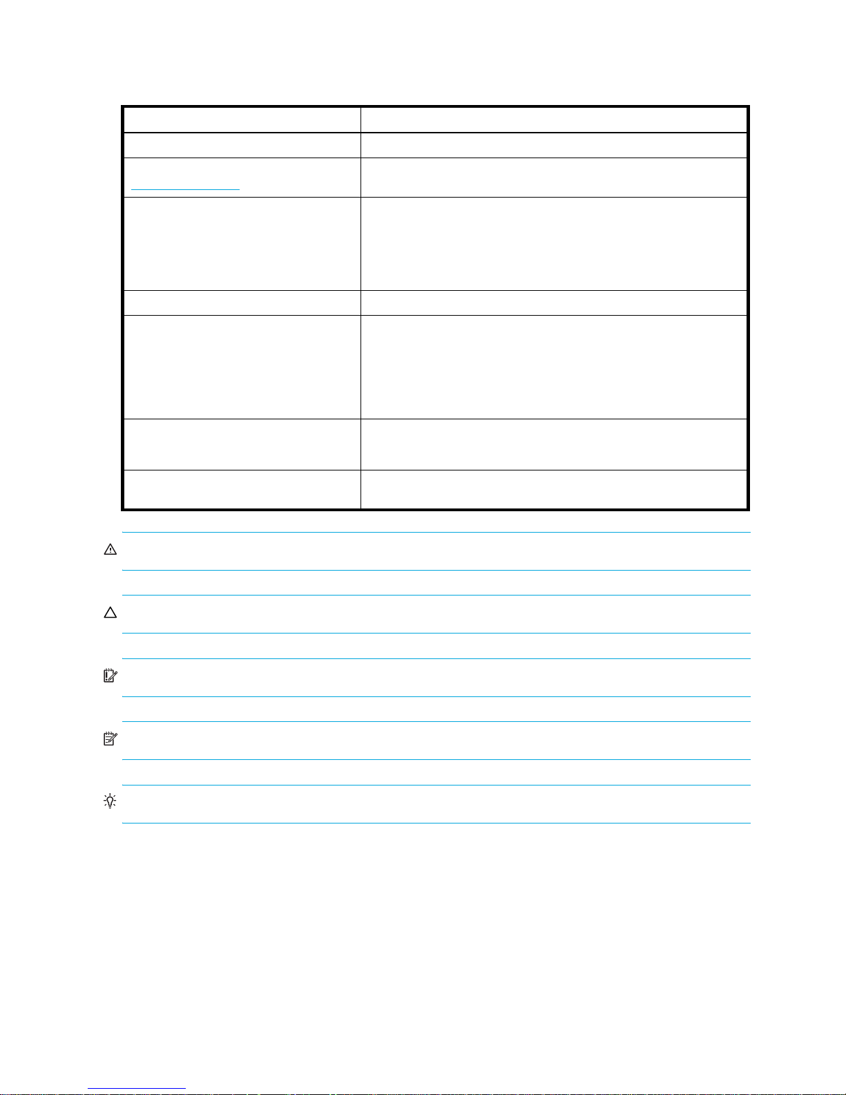
Table 1 Document conventions
Convention Element
Medium blue text: Figure 1 Cross-reference links and e-mail addresses
Medium blue, underlined text
(http://www.hp.com)
Bold font • Key names
Italics font Text emphasis
Monospace font • File and directory names
Monospace, italic font • Code variables
Monospace, bold font Emphasis of file and directory names, system output, code, and text
Web site addresses
• Text typed into a GUI element, such as into a box
• GUI elements that are clicked or selected, such as menu and list
items, buttons, and check boxes
• System output
• Code
• Text typed at the command-line
• Command-line variables
typed at the command line
WARNING! Indicates that failure to follow directions could result in bodily harm or death.
CAUTION: Indicates that failure to follow directions could result in damage to equipment or data.
IMPORTANT: Provides clarifying information or specific instructions.
NOTE: Provides additional information.
TIP: Provides helpful hints and shortcuts.
14
Page 15

HP technical support
Telephone numbers for worldwide technical support are listed on the HP support web site:
http://www.hp.com/support/
Collect the following information before calling:
• Technical support registration number (if applicable)
• Product serial numbers
• Product model names and numbers
• Applicable error messages
• Operating system type and revision level
• Detailed, specific questions
For continuous quality improvement, calls may be recorded or monitored.
HP strongly recommends that customers sign up online using the Subscriber's choice web site:
http://www.hp.com/go/e-updates
• Subscribing to this service provides you with e-mail updates on the latest product enhancements,
newest versions of drivers, and firmware documentation updates as well as instant access to numerous
other product resources.
• After signing up, you can quickly locate your products by selecting Business support and then Storage
under Product Category.
HP-authorized reseller
.
.
For the name of your nearest HP-authorized reseller:
• In the United States, call 1-800-282-6672.
• Elsewhere, visit the HP web site: http://www.hp.com
telephone numbers.
Helpful web sites
For other product information, see the following HP web sites:
• http://www.hp.com
• http://www.hp.com/go/storage
• http://www.hp.com/support/
• http://www.docs.hp.com
. Then click Contact HP to find locations and
Fabric OS 5.x diagnostics and system error messages reference guide 15
Page 16

16
Page 17
1 Fabric OS command line interface
This chapter explains the different methods used to manage HP SAN and HP StorageWorks switches. The
following information is discussed:
• Understanding access levels, page 17
• Using the Fabric OS command line interface, page 18
• Using this guide, page 19
Understanding access levels
Fabric OS supports two classes of user accounts: default and multiple user account (MUA).
Default accounts, introduced in early versions of Fabric OS, include root, factory, admin, and user.
• The root and factory levels are reserved for support and manufacturing personnel.
• The admin accounts are intended for general switch and fabric administration activities. The admin
role can perform all Fabric OS operations.
• The user accounts are intended for general switch and fabric administration activities. The user role
performs observation-only operations.
• Each account has hard-coded permissions that define roles whose privileges correspond to the
account name.
In HP’s Fabric OS 3.x and earlier, multiple-user access to a switch is limited. Each switch enables only a
single session per access method, regardless of the user’s access level. Switches can, however, be
accessed simultaneously from different connections; for example, through the command line interface
(CLI) and HP Web Tools. If this happens, changes from one connection might not be updated to the other,
and some changes might be lost. When you connect using simultaneous multiple connections, ensure that
you do not overwrite the work of another connection.
In Fabric OS v5.x, multiple sessions are allowed. Each access level can have the number of simultaneous
logins shown in Table 2.
Table 2 Fabric OS v5.x user access maximum sessions
User name Maximum number of simultaneous sessions
admin 2
user 4
The MUA feature distinguishes between a user account and the role assigned to the account. The
switchAdmin role, introduced in Fabric OS v5.x, has most of the existing administrative permissions,
Fabric OS 5.x command reference guide 17
Page 18
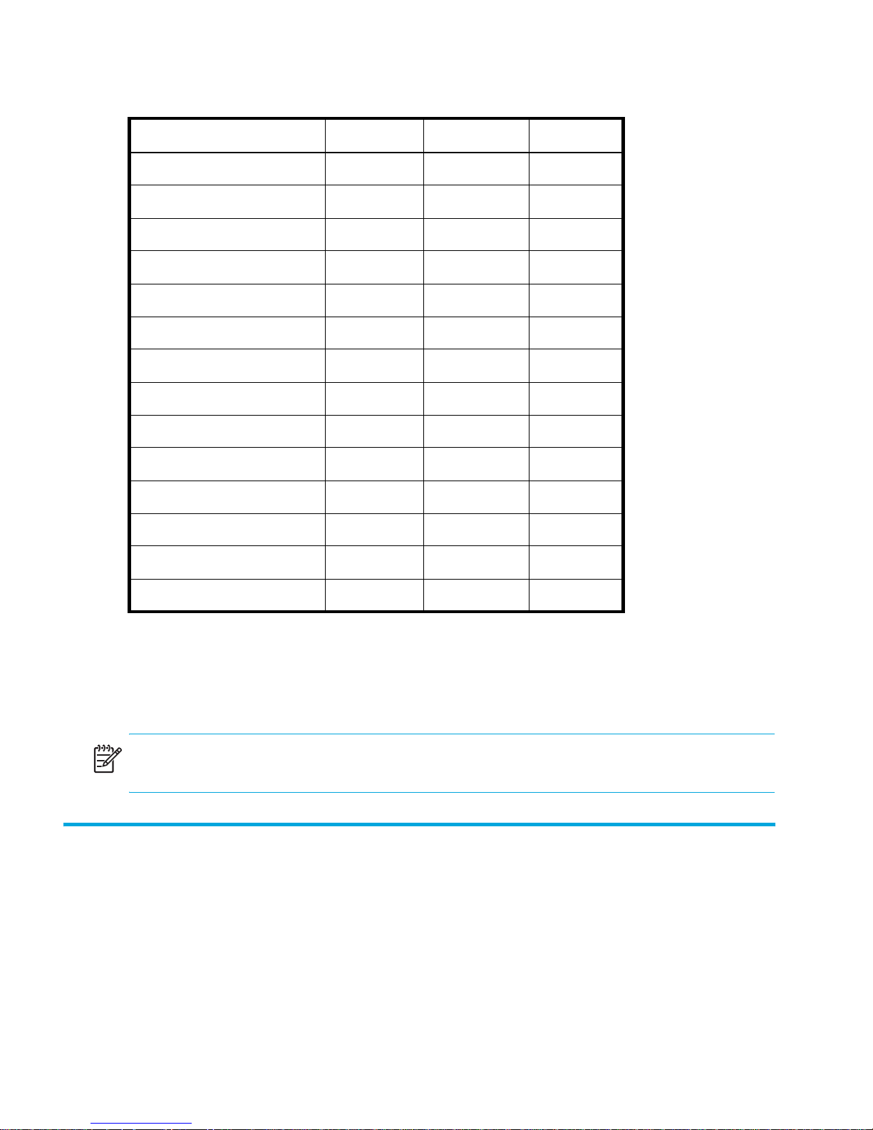
except the ability to perform zone and security configuration and user management. See Table 3 for a
high-level description of role permissions.
Table 3 Role permissions
Functional Area user switchAdmin admin
Zone configuration View View Modify
Environmental View Modify Modify
Logs (RAS) View Modify Modify
Security View View Modify
Switch configuration View Modify Modify
Switch management View Modify Modify
Port configuration View Modify Modify
SNMP View Modify Modify
Diagnostics View Modify Modify
Devices View Modify Modify
User management View N.A. Modify
Fabric Watch View Modify Modify
Advanced Performance Monitor View Modify Modify
Admin domain management View N.A. Modify
The MUA feature was introduced in Fabric OS v3.2.0/v4.4.0 and the switchAdmin can log in; however,
the role is restricted to user-level, observation-based functions.
This manual lists all the commands available to the user- and admin-level logins. See ”MUA-based roles”
on page 777 for commands available to the switchAdmin role.
NOTE: The admin access level has access to all the commands needed to manage and configure a
switch or fabric. The admin account is the recommended login level.
Using the Fabric OS command line interface
The Fabric OS command line interface (CLI), accessed through either telnet or serial console, provides an
administrator with full management capability on an HP StorageWorks switch. The Fabric OS CLI
enables an administrator to monitor and manage entire fabrics, individual switches, and ports from a
standard workstation. The entire suite of Fabric OS features and capabilities is available across an entire
fabric, from a single access point. Selected commands must be issued from a sectelnet or SSH session, as
indicated in the command description in this manual.
Access is controlled by a switch-level password for each access level. The commands available through
the CLI are based on the user’s login level and the license keys used to unlock certain features.
Fabric OS CLI is the complete fabric management tool for HP SANs and provides the following:
18 Fabric OS command line interface
Page 19

• Access to the full range of Fabric OS features, based on which license keys you purchase
• Assistance with configuration, monitoring, dynamic provisioning, and daily management of every
aspect of storage area networks
• A deeper view of the tasks involved in managing a StorageWorks switch or director
• Configuration and management of the HP fabric on multiple levels
• Identification, isolation, and management of SAN events across every switch in the fabric
• Management switch licenses
Using this guide
This guide describes each command, including a synopsis of its syntax and the users to which it is
available, and provides a description of command usage and behavior. The same information is
available to you on your HP StorageWorks SAN Switch or Director, using the help command. For
example, to display the help or man page for aliAdd, type:
switch:admin> help aliadd
Fabric OS 5.x command reference guide 19
Page 20

20 Fabric OS command line interface
Page 21

2 Fabric OS commands
This chapter lists the Fabric OS commands. It also shows their syntax and operands, and provides
examples of their usage.
Fabric OS 5.x command reference guide 21
Page 22
Synopsis
Availability
Description
aaaConfig
Manages RADIUS configuration information.
aaaconfig [action] [options]
admin
Use this command to manage the RADIUS configuration for the authentication, authorization, and
accounting (AAA) services. This command displays, adds, removes, changes, enables, or disables
RADIUS configuration.
When the command completes, any new configuration is saved persistently. It is effective for the next
AAA request. The configuration applies to all switch instances in a platform supporting multiple switch
domains.
Use the centralized RADIUS servers to manage AAA services for a switch, as defined in RFC 2865.
NOTE: This command can be executed when you are logged in through the console, or a serial or SSH
connection.
Operands
The command takes as input an action and its associated options. Without any specified action, the
command displays the usage. Specify action as one of following:
--show Displays the current AAA service configuration.
--add server [options] Adds a RADIUS server to the configuration.
--remove server Removes a RADIUS server from the configuration.
--change server [options] Changes a RADIUS server configuration.
--move server to_position Moves a RADIUS server from the current position to a new
position. When server is a required operand for an action, it
must be either an IP address or a name in dot notation. If a
name is used, DNS must be properly configured.
--radius [on | off] Turns on or off the current RADIUS configuration.
--switchdb [on | off] Turns on or off the switch local database as secondary
authentication.
The following are the options for the --add and --change actions:
-p port RADIUS server port number
-s secret Common secret between the switch and RADIUS server
-t timeout Response timeout for the RADIUS server
-a [pap | chap] Use PAP or CHAP as authentication protocol
22 Fabric OS commands
Page 23

The following provides a detailed description of each action type:
--show List the current RADIUS servers, along with their parameters.
Fabric OS 5.x command reference guide 23
Page 24

--add server [-p port] [-s secret] [-t timeout] [-a chap | pap]
Add the specified server to the end of the RADIUS
configuration list, with the specified port number, shared
secret, timeout, and if PAP or CHAP is to be used as
authentication protocol. server must be different from the
servers in the existing configuration.
--remove server Remove the specified server from the RADIUS configuration
list.server must match a server in the existing configuration.
To remove the last server, you must disable the RADIUS
configuration first.
--change server [-p port] [-s secret] [-t timeout] [-a chap | pap]
Change parameters for the specified server in the existing
RADIUS configuration list. server must match one in the
existing configuration.
--move server to_position Move the specified server in the existing RADIUS configuration
list from the current position to the specified new position. This
rearranges the order in which the specified RADIUS server is
used.
--radius [on | off] Enable or disable the current RADIUS configuration for AAA
services. This is used to switch the primary AAA services
between RADIUS and the switch local database. To enable the
RADIUS configuration, there must be at least one server
existing in the configuration.
--switchdb [on | off] Enable or disable the switch local database as the secondary
AAA services. When enabled, if RADIUS requests a timeout for
all RADIUS servers, the switch local database is used for
authentication; otherwise, requests are denied.
Examples
See also
To display the current RADIUS configuration:
switch:admin> aaaconfig --show
Position Server Port Secret Timeout(s) Auth-Protocol
1 192.168.233.48 1812 sharedsecret 3 CHAP
2 192.168.233.44 1812 sharedsecret 3 CHAP
3 radserver 1812 private 5 CHAP
Primary AAA Service: Switch database
Secondary AAA Service: None
To change the configuration for server 192.168.233.48:
switch:admin> aaaconfig --change 192.168.233.48 -p 3002 -s newsecret -t 1
none
24 Fabric OS commands
Page 25

Synopsis
Availability
Description
agtCfgDefault
Resets the SNMP agent configuration to default values.
agtcfgdefault
admin
Use this command to reset the SNMP agent configuration with the switch default values.
This command prompts the user and proceeds to reset only on the user’s confirmation. All new values
successfully configured by the command take effect immediately. These changes are persistent across
power cycles and reboots. For dual-domain systems, agtCfgDefault operates on the SNMP agent
associated with the current switch.
This command resets the following values (See the HP StorageWorks Fabric OS 5.x MIB reference guide
for detailed sysDescr, sysLocation, and sysContact descriptions):
sysDescr The system (switch) description. The default value is Fibre Channel Switch in most
platforms; however, the default system description value is platform-specific.
Different values might appear as the default for some specialized platforms.
sysLocation The location of the system. The default value is End User Premise.
sysContact The contact information for the system. The default value is Field Support.
authTraps When enabled, the authentication trap, authenticationFailure, is transmitted to a
configured trap recipient in the event the agent received a protocol message that
is not properly authenticated. In the context of SNMPv1 and SNMPv2c, this
means that a request contains a community string that is not known to the agent.
The default value for this parameter is 0 (disabled).
There are six communities and respective trap recipients supported by the agent. The first three
communities are for read-write (rw) access and the last three are for read-only (ro) access. The default
value for the trap recipient of each community is 0.0.0.0. The default values for the community strings are
as follows:
• Community 1: Secret Code
• Community 2: OrigEquipMfr
• Community 3: private
• Community 4: public
• Community 5: common
• Community 6: FibreChannel
For an SNMP management station to receive a trap generated by the agent, the administrator must
configure a trap recipient to correspond to the IP address of the management station. In addition, the trap
recipient must be able to pass the access control list (ACL) check.
Trap recipient severity level
The trap severity level is associated with each trap recipient IP address. The event trap level is in
conjunction with the event's severity level. When an event occurs and if its severity level is at or below the
set value, the SNMP event traps (swEventTrap, swFabricWatchTrap, and connUnitEventTrap)
Fabric OS 5.x command reference guide 25
Page 26

are sent to the trap recipients. By default, this value is set to 0, implying that no such traps are sent.
Possible values are as follows:
0none
1critical
2error
3 warning
4 informational
5debug
See errModuleShow for related information.
The ACL check is as follows: there are six ACLs to restrict SNMP get/set/trap operations to hosts under a
host-subnet-area. Host-subnet-area is defined by comparing nonzero IP octets. For example, an ACL of
192.168.64.0 enables access by any hosts that start with the specified octets. The connecting host is
enabled to set each host-subnet-area to be read-write or read-only. The highest privilege matched out of
six entries is given to the access. The ACL check is turned off when all six entries contain 0.0.0.0.
NOTE: When secure mode is enabled, the access control list feature is incorporated into the WSNMP
and RSNMP security policies. Community strings can be changed on the primary FCS switch only and
will propagate changes across the fabric.
Operands
Examples
none
To reset the SNMP agent to default values:
switch:admin> agtcfgdefault
*****
This command will reset the agent's configuration back to factory
default
*****
Current SNMP Agent Configuration
Customizable MIB-II system variables:
sysDescr = Fibre Channel Switch.
sysLocation = End User Premise
sysContact = sweng
authTraps = 0 (OFF)
(continued on next page)
26 Fabric OS commands
Page 27

SNMPv1 community and trap recipient configuration:
Community 1: Secret C0de (rw)
Trap recipient: 192.168.15.41
Trap recipient Severity level: 4
Community 2: OrigEquipMfr (rw)
No trap recipient configured yet
Community 3: private (rw)
No trap recipient configured yet
Community 4: public (ro)
No trap recipient configured yet
Community 5: common (ro)
No trap recipient configured yet
Community 6: FibreChannel (ro)
No trap recipient configured yet
SNMP access list configuration:
Entry 0: Access host subnet area 192.168.64.0 (rw)]
Entry 1: No access host configured yet
Entry 2: No access host configured yet
Entry 3: No access host configured yet
Entry 4: No access host configured yet
Entry 5: No access host configured yet
*****
Are you sure? (yes, y, no, n): [no] y
Committing configuration...done.
agent configuration reset to factory default
Current SNMP Agent Configuration
Customizable MIB-II system variables:
sysDescr = Fibre Channel Switch.
sysLocation = End User Premise
sysContact = Field Support.
authTraps = 0 (OFF)
(continued on next page)
Fabric OS 5.x command reference guide 27
Page 28

SNMPv1 community and trap recipient configuration:
Community 1: Secret C0de (rw)
No trap recipient configured yet
Community 2: OrigEquipMfr (rw)
No trap recipient configured yet
Community 3: private (rw)
No trap recipient configured yet
Community 4: public (ro)
No trap recipient configured yet
Community 5: common (ro)
No trap recipient configured yet
Community 6: FibreChannel (ro)
No trap recipient configured yet
SNMP access list configuration:
Entry 0: No access host configured yet
Entry 1: No access host configured yet
Entry 2: No access host configured yet
Entry 3: No access host configured yet
Entry 4: No access host configured yet
Entry 5: No access host configured yet
See also
agtCfgSet
agtCfgShow
snmpConfig
28 Fabric OS commands
Page 29

Synopsis
Availability
Description
agtCfgSet
Modifies the SNMP agent configuration.
agtcfgset
admin
Use this command to modify the configuration of the SNMP agent in the switch.
All values successfully configured by this command take effect immediately. These values are persistent
across power cycles and reboots. For dual-domain systems, this command operates on the SNMP agent
associated with the current switch.
This command updates the following values (See the HP StorageWorks Fabric OS 5.x MIB reference
guide for detailed sysDescr, sysLocation, and sysContact descriptions):
sysDescr The system (switch) description. The default value is Fibre Channel
Switch in most platforms; however, the default system description
value is platform specific. Different values might appear as the
default for some specialized platforms.
sysLocation The location of the system. The default value is End User Premise.
sysContact The contact information for the system. The default value is Field
Support.
authTrapsEnabled When enabled, the authentication trap, authenticationFailure, is
transmitted to a configured trap recipient in the event the agent
received a protocol message that is not properly authenticated. In
the context of SNMPv1 and SNMPv2c, this means that a request
contains a community string that is not known to the agent. The
default value for this parameter is 0 (disabled).
There are six communities and respective trap recipients supported by the agent. The first three
communities are for read-write (rw) access and the last three are for read-only (ro) access. The default
value for the trap recipient of each community is 0.0.0.0. The default values for the community strings are
as follows:
• Community 1: Secret Code
• Community 2: OrigEquipMfr
• Community 3: private
• Community 4: public
• Community 5: common
• Community 6: FibreChannel
For an SNMP management station to receive a trap generated by the agent, the administrator must
configure a trap recipient to correspond to the IP address of the management station. In addition, the trap
recipient must be able to pass the access control list (ACL) check.
Fabric OS 5.x command reference guide 29
Page 30

Trap recipient severity level
The trap severity level is associated with each trap recipient IP address. The event trap level is in
conjunction with the event's severity level. When an event occurs and if its severity level is at or below the
set value, the SNMP event traps (swEventTrap, swFabricWatchTrap, and connUnitEventTrap)
are sent to the trap recipients. By default, this value is set to 0, implying that no such traps are sent.
Possible values are as follows:
0none
1critical
2error
3 warning
4 informational
5debug
See errModuleShow for related information.
The ACL check is as follows: there are six ACLs to restrict SNMP get/set/trap operations to hosts under a
host-subnet-area. Host-subnet-area is defined by comparing nonzero IP octets. For example, an ACL of
192.168.64.0 enables access by any hosts that start with the specified octets. The connecting host is
enabled to set each host-subnet-area to be read-write or read-only. The highest privilege matched out of
six entries is given to the access. The ACL check is turned off when all six entries contain 0.0.0.0.
Operands
Examples
NOTE: When secure mode is enabled, the access control list feature is incorporated into the WSNMP
and RSNMP security policies. Community strings can be changed on the primary FCS switch only and
will propagate changes across the fabric.
none
To modify the SNMP configuration values:
switch:admin> agtcfgset
Customizing MIB-II system variables ...
At each prompt, do one of the followings:
o <Return> to accept current value,
o enter the appropriate new value,
o <Control-D> to skip the rest of configuration, or
o <Control-C> to cancel any change.
(continued on next page)
30 Fabric OS commands
Page 31

To correct any input mistake:
<Backspace> erases the previous character,
<Control-U> erases the whole line,
sysDescr: [FC Switch]
sysLocation: [End User Premise]
sysContact: [Field Support.]
authTrapsEnabled (true, t, false, f): [true]
SNMP community and trap recipient configuration:
Community (rw): [Secret C0de]
Trap Recipient's IP address in dot notation: [192.168.1.51]
Trap recipient Severity level : (0..5) [0] 3
Community (rw): [OrigEquipMfr]
Trap Recipient's IP address in dot notation: [192.168.1.26]
Trap recipient Severity level : (0..5) [0]
Community (rw): [private]
Trap Recipient's IP address in dot notation: [0.0.0.0] 192.168.64.88
Trap recipient Severity level : (0..5) [0] 1
Community (ro): [public]
Trap Recipient's IP address in dot notation: [0.0.0.0]
Community (ro): [common]
Trap Recipient's IP address in dot notation: [0.0.0.0]
Community (ro): [FibreChannel]
Trap Recipient's IP address in dot notation: [0.0.0.0]
SNMP access list configuration:
Access host subnet area in dot notation: [0.0.0.0] 192.168.64.0
Read/Write? (true, t, false, f): [true]
Access host subnet area in dot notation: [0.0.0.0]
Read/Write? (true, t, false, f): [true]
Access host subnet area in dot notation: [0.0.0.0]
Read/Write? (true, t, false, f): [true]
Access host subnet area in dot notation: [0.0.0.0]
Read/Write? (true, t, false, f): [true]
Access host subnet area in dot notation: [0.0.0.0]
Read/Write? (true, t, false, f): [true]
Access host subnet area in dot notation: [0.0.0.0]
Read/Write? (true, t, false, f): [true]
Committing configuration...done.
value = 1 = 0x1
See also
agtCfgDefault
agtCfgShow
snmpConfig
SW_v5_x.mib, Switch Management Information & Switch Enterprise Specific Trap
RFC1157, A Simple Network Management Protocol (SNMPv1)
RFC1213, Management information Base for Network Management of TCP/IP-based internets: MIB-II
Fabric OS 5.x command reference guide 31
Page 32
agtCfgShow
Displays the SNMP agent configuration.
Synopsis
agtcfgshow
Availability
all users
Description
Use this command to display the configuration of the SNMP agent in the switch.
NOTE: On a dual-switch chassis, there is one SNMP agent per logical switch. This command is specific
to the logical switch you are logged in to.
The following information displays:
sysDescr The system (switch) description. The default value is Fibre Channel Switch.
sysLocation The location of the system. The default value is End User Premise.
sysContact The contact information for the system. The default value is Field Support.
authTrapsEnabled When enabled, the authentication trap, authenticationFailure, is
See the HP StorageWorks Fabric OS 5.x MIB reference guide for detailed
sysDescr, sysLocation, and sysContact descriptions.
transmitted to a configured trap recipient in the event that the agent received
a protocol message that is not properly authenticated. In the context of
SNMPv1 and SNMPv2c, this means that a request contains a community
string that is not known to the agent. The default value for this parameter is
0 (disabled).
There are six communities, respective trap recipients, and trap recipients supported by the agent. The first
three communities are for read-write (rw) access and the last three are for read-only (ro) access. The
default value for the trap recipient of each community is 0.0.0.0. The community string length ranges
from 2 to 16 characters. The default values for the community strings are:
• Community 1: Secret C0de
• Community 2: OrigEquipMfr
• Community 3: private
• Community 4: public
• Community 5: common
• Community 6: FibreChannel
For an SNMP management station to receive a trap generated by the agent, the administrator must
configure a trap recipient to correspond to the IP address of the management station. In addition, the trap
recipient must be able to pass the access control list (ACL) check.
32 Fabric OS commands
Page 33

Trap recipient severity level
The event trap level in conjunction with the event's severity level. When an event occurs and if its severity
level is at or below the set value, the SNMP trap, swEventTrap, is sent to configured trap recipients. By
default, this value is set to 0, implying that no swEventTrap is sent. Possible values are:
0none
1critical
2error
3 warning
4informational
5debug
See errShow for related information.
The ACL check is as follows: there are six ACLs to restrict SNMP get/set/trap operations to hosts under a
host-subnet-area. Host-subnet-area is defined by comparing nonzero IP octets. For example, an ACL of
192.168.64.0 enables access by any hosts that start with the specified octets. The connecting host is
enabled to set each host-subnet-area to be read-write or read-only. The highest privilege matched out of
six entries is given to the access. The ACL check is turned off when all six entries contain 0.0.0.0.
NOTE: When secure mode is enabled, the access control list feature is incorporated into the WSNMP
and RSNMP security policies. Community strings can be changed on the primary FCS switch only and
will propagate changes across the fabric.
Operands
Examples
none
switch:admin> agtcfgshow
Current SNMP Agent Configuration
Customizable MIB-II system variables:
sysDescr = FC Switch
sysLocation = End User Premise
sysContact = Field Support.
authTraps = 1 (ON)
SNMPv1 community and trap recipient configuration:
Community 1: Secret C0de (rw)
Trap recipient: 192.168.1.51
Trap recipient Severity level: 4
Community 2: OrigEquipMfr (rw)
Trap recipient: 192.168.1.26
Trap recipient Severity level: 0
Community 3: private (rw)
No trap recipient configured yet
(continued on next page)
Fabric OS 5.x command reference guide 33
Page 34

See also
Community 4: public (ro)
No trap recipient configured yet
Community 5: common (ro)
No trap recipient configured yet
Community 6: FibreChannel (ro)
No trap recipient configured yet
SNMP access list configuration:
Entry 0: Access host subnet area 192.168.64.0 (rw)]
Entry 1: No access host configured yet
Entry 2: No access host configured yet
Entry 3: No access host configured yet
Entry 4: No access host configured yet
Entry 5: No access host configured yet
agtCfgDefault
agtCfgSet
snmpConfig
34 Fabric OS commands
Page 35
aliAdd
Synopsis
Availability
Description
Adds a member to a zone alias.
aliadd “aliName“, “ member; member“
admin
NOTE: This command requires HP Advanced Zoning, which is included within the Base Configuration
Services and bundled with each B-series switch.
Use this command to add one or more members to an existing zone alias. The alias member list cannot
contain another zone alias.
This command changes the defined configuration. For the change to be preserved across switch reboots,
it must be saved to flash memory using the cfgSave command. For the change to become effective, an
appropriate zone configuration must be enabled using the cfgEnable command.
Operands
Examples
NOTE: When security is enabled, this command can be issued only from the primary FCS switch.
This command has the following required operands:
“aliName“ Specify the name of a zone alias, in quotation marks.
“member“ Specify a member or list of members to be added to the alias, in
quotation marks, separated by semicolons. An alias member
can be specified by one or more of the following methods:
• A switch domain and port area number pair. View the area
numbers for ports using the switchShow command.
• WWN
• QuickLoop AL_PAs
To add members to zone aliases array1, array2, and loop1:
switch:admin> aliadd "array1", "1,2"
switch:admin> aliadd "array2", "21:00:00:20:37:0c:72:51"
switch:admin> aliadd "loop1", "4,5[0x02]; 6,7[0xEF]"
Fabric OS 5.x command reference guide 35
Page 36

See also
aliCreate
aliDelete
aliRemove
aliShow
36 Fabric OS commands
Page 37

aliasDelete
Deletes a port from all local groups.
Synopsis
aliasDelete portID
Availability
admin
Description
Use this command to delete a local port from all local groups. The group is deleted if it becomes empty
after deleting the local port.
Use the aliasShow command to show the existing groups with its corresponding N_Ports.
Operands
The following aliasDelete argument is required.
Examples
To delete a port from an existing group:
portID The port ID in its hexadecimal representation
Exit status
See also
switch:admin> aliasdelete 0x19c00
aliasDelete: succeeded
0Successful operation
nonzero Indicates the operation has failed
aliasJoin
aliasShow
fabricShow
switchShow
Fabric OS 5.x command reference guide 37
Page 38

aliasJoin
Synopsis
Availability
Description
Operands
Creates a multicast alias group of N_Ports. If the group already exists, the N_Ports are added to the
existing group.
aliasJoin
admin
Use this command to create a multicast alias group of N_Ports or to add N_Ports to an existent group.
Any online N_Port defined in the fabric can be part of a group. An N_Port can be added from any switch
that is part of the fabric.
To get a list of online ports currently defined in the fabric, use the nsAllShow command. If the user
wants to add only local ports associated with the local switch, use the nsShow command to get list of
ports associated with the local switch.
none
Examples
To create an alias group of N_Ports or to add N_Ports to an existing group:
switch:admin> aliasJoin
aliasJoin: To add ports to an existing or new multicast group
Number of ports in the group: (1..64) [1]
To set an authorization password? (yes, y, no, n): [no]
no password
Setting the authorization control
Add control: 0 by any, 1 only itself, 2 by creator: (0..2) [0]
Del control: 0 by any, 1 only itself, 2 by creator: (0..2) [0]
Lsn control: 0 by any, 1 by none: (0..1) [1]
Add control 0, Del control 0 Lsn control 1
Setting the Routing Bit: (0x0..0xc) [0x0]
using FC-4 Device Data ...
Setting FC-4 Type: (0x0..0x5d) [0x5]
using 0x05 ...
To set the alias qualifier in WWN format? (yes, y, no, n): [yes]
Qualifier (in hex): [10:00:00:60:69:80:02:28]
Port ID (in hex): (0x0..0xeffa00) [0] 0x19c00
npList[0] = 0x19c00
aliasJoin: Join request to Group Address 0xfffb00 succeeds
38 Fabric OS commands
Page 39

Exit status
See also
0Successful operation
nonzero Indicates the operation has failed
aliasDelete
aliasPurge
aliasShow
fabricShow
nsAllShow
nsShow
Fabric OS 5.x command reference guide 39
Page 40

aliasPurge
Removes an alias group.
Synopsis
aliasPurge groupID
Availability
admin
Description
Use this command to remove an alias group.
Operands
The following aliasPurge argument is required.
Examples
To remove an alias group:
groupID It is the group ID in its hexadecimal representation
Exit status
See also
switch:admin> aliasPurge 0xfffb00
aliasPurge: succeeded
0Successful operation
nonzero Indicates the operation has failed
aliasJoin
aliasShow
fabricShow
switchShow
40 Fabric OS commands
Page 41

aliasShow
Displays local alias server information.
Synopsis
aliasShow
Availability
all users
Description
Use this command to display local information. If there is no local alias group, a message is displayed. If
there are multiple entries in the local alias group, they are displayed.
Operands
none
Examples
To display the entries in the local alias server:
switch:admin> aliasShow
{AliasID Creator Token [rb, type, grptype, qlfr] Member List
Exit status
See also
fffb00 fffffd [00, 05, 10, 10000060 69800228] { 019c00 }
}
The Local Alias Server has 1 entry
0Successful operation
nonzero Indicates the operation has failed
fabricShow
switchShow
Fabric OS 5.x command reference guide 41
Page 42
aliCreate
Synopsis
Availability
Description
Creates a zone alias.
alicreate “aliName“, “member; member“
admin
NOTE: This command requires HP Advanced Zoning, which is included within the Base Configuration
Services and bundled with each B-series switch.
Use this command to create a new zone alias. The zone alias member list must have at least one member
(empty lists are not allowed). The alias member list cannot contain another zone alias. See the
zoneCreate command for more information on name and member specifications.
Zone alias members can be specified using the area number to represent a specific port and slot
combination. Area numbers are automatically assigned to a port by the Fabric OS. You can view the
Area numbers using the switchShow command.
Operands
This command changes the defined configuration. For the change to be preserved across switch reboots,
it must be saved to flash memory using the cfgSave command. For the change to become effective, an
appropriate zone configuration must be enabled using the cfgEnable command.
NOTE: When security is enabled, this command can be issued only from the primary FCS switch.
This command has the following operands:
“aliName” Specify a name for the zone alias, in quotation marks. This
operand is required. A zone alias name must begin with a letter
and can be followed by any number of letters, digits and
underscore characters. Names are case sensitive: for example,
“Ali_1” and “ali_1” are different zone aliases. Spaces are
ignored.
“member” Specify a member or list of members to be added to the alias, in
quotation marks, separated by semicolons. An alias member
can be specified by one or more of the following methods:
• A switch domain and port area number pair. View the area
numbers for ports using the switchShow command.
42 Fabric OS commands
• WWN
• QuickLoop AL_PAs
This operand is required.
Page 43

Examples
See also
To create a zone alias:
switch:admin> alicreate "array1", "2,32; 2,33; 2,34"
switch:admin> alicreate "array2", "21:00:00:20:37:0c:66:23"
switch:admin> alicreate "loop1", "4,5[0x02]; 6,7[0xEF]; 5,4"
aliAdd
aliDelete
aliRemove
aliShow
Fabric OS 5.x command reference guide 43
Page 44
aliDelete
Synopsis
Availability
Description
Deletes a zone alias.
alidelete “aliName“
admin
NOTE: This command requires HP Advanced Zoning license, which is included within the Base
Configuration Services and bundled with each B-series switch.
Use this command to delete a zone alias.
This command changes the defined configuration. For the change to be preserved across switch reboots,
it must be saved to flash memory using the cfgSave command. For the change to become effective, an
appropriate zone configuration must be enabled using the cfgEnable command.
Operands
Examples
See also
NOTE: When security is enabled, this command can be issued only from the primary FCS switch.
This command has the following operand:
“aliName” Specify the name of zone alias to be deleted. This
operand must be enclosed in quotation marks. This
operand is required.
To delete the zone alias array2:
switch:admin> alidelete "array2"
aliAdd
aliCreate
aliRemove
aliShow
44 Fabric OS commands
Page 45
aliRemove
Removes a member from a zone alias.
Synopsis
aliremove “aliName“, “member; member“
Availability
admin
NOTE: This command requires HP Advanced Zoning license, which is included within the Base
Configuration Services and bundled with each B-series switch.
Description
Use this command to remove one or more members from an existing zone alias.
If all members are removed, the zone alias is deleted.
This command changes the defined configuration. For the change to be preserved across switch reboots,
it must be saved to flash memory using the cfgSave command. For the change to become effective, an
appropriate zone configuration must be enabled using the cfgEnable command.
Operands
NOTE: When security is enabled, this command can be issued only from the primary FCS switch.
This command has the following operands:
“aliName“ Specify the name of the zone alias to have members removed, in
quotation marks. This operand is required.
“member“ Specify a member or list of members to be removed from the
alias, in quotation marks, separated by semicolons. An alias
member can be specified by one or more of the following
methods:
• A switch domain and port area number pair. View the area
numbers for ports using the switchShow command.
• WWN
• QuickLoop AL_PAs
This operand is required. The member list is located by an exact
string match; therefore, it is important to maintain the order
when removing multiple members. For example, if a zone alias
contains “1,2; 1,3; 1,4”, then removing“1,3; 1,4” succeeds but
removing “1,4; 1,3” fails.
Fabric OS 5.x command reference guide 45
Page 46

Examples
See also
Remove a world wide name from “array1”:
switch:admin> aliremove "array1", "3,5"
switch:admin> aliremove "array1", "21:00:00:20:37:0c:76:8c"
switch:admin> aliremove "array1", "0xEF"
aliAdd
aliCreate
aliDelete
aliShow
46 Fabric OS commands
Page 47
aliShow
Synopsis
Availability
Description
Displays zone alias information.
alishow [“pattern“][, mode]
all users
NOTE: This command requires HP Advanced Zoning license, which is included within the Base
Configuration Services and bundled with each B-series switch.
Use this command to display zone configuration information.
If a parameter is specified, it is used as a pattern to match zone alias names; those that match in the
defined configuration are displayed.
Operands
NOTE: When security is enabled, this command can be issued only from the primary FCS switch.
This command has the following optional operands:
“pattern“ A POSIX-style regular expression used to match zone alias
names. This operand must be enclosed in quotation marks.
Patterns can contain:
• Question mark (?), which is a placeholder for any single
character
• Asterisk (*), which is a placeholder for any string of
characters
• Ranges, which are a placeholder for any character within the
range. Ranges must be enclosed in brackets: for example,
[0-9] or [a-f].
mode Specify 0 to display the contents of the transaction buffer (the
contents of the current transaction), or specify 1 to display the
contents of the flash memory. The default value is 0
If no parameters are specified, all zone configuration information (both defined and effective) is
displayed. See cfgShow for a description of this display.
Examples
To display all zone aliases beginning with “arr”:
switch:admin> alishow "arr*"
alias: array1 21:00:00:20:37:0c:76:8c
alias: array2 21:00:00:20:37:0c:66:23
Fabric OS 5.x command reference guide 47
Page 48

See also
aliAdd
aliCreate
aliDelete
aliRemove
48 Fabric OS commands
Page 49

aptPolicy
Synopsis
Availability
Description
Operands
Changes or displays the Advanced Performance Tuning (APT) policy.
aptpolicy [policy]
admin
Use this command, which changes several internal parameters, to change the performance algorithm on
the switch. (A detailed performance-tuning discussion is beyond the scope of this manual.) The default
parameters are optimal for most SAN applications; typically, customers do not need to use this
command.
When used with no arguments, this command displays a list of APT policies supported on this switch, as
well as the current policy. This can be done at any time.
The switch must be disabled before using this command to change the current policy.
This command has the following operand:
policy Specifies the new APT policy. The following polices are supported:
• Port-based routing policy
With this policy, the path chosen for an ingress frame is based on:
• Ingress port on which the frame was received
• Destination domain for the frame
The chosen path remains the same if Dynamic Load Sharing (DLS) feature is
not enabled. If DLS is enabled, then a different path may be chosen on a
fabric event. See dlsSet for the definition of a fabric event.
This policy may provide better ISL utilization when there is little or no
oversubscription of the ISLs.
Note that static routes are supported only with this policy.
• Device-based routing policy
With this policy, the path chosen for an ingress frame is based on:
• Ingress port on which the frame was received
• FC address of the source fabric device (SID) for this frame
• FC address of the destination fabric device (DID) for this frame
This policy allows for better utilization of the available paths as I/O traffic
between different (SID, DID) pairs can use different paths. All frames received
on a ingress port with the same (SID, DID) parameters takes the same path
unless there is a fabric event. See dlsSet for the definition of a fabric event.
This policy does not support static routes. DLS always is enabled and the DLS
setting cannot change with this policy.
Fabric OS 5.x command reference guide 49
Page 50

Examples
• Exchange-based routing policy
With this policy, the path chosen for an ingress frame is based on:
Ingress port on which the frame was received
• FC address of the SID for this frame
• FC address of the DID for this frame
• FC Originator Exchange ID (OXID) for this frame
This policy allows for optimal utilization of the available paths as I/O traffic
between different (SID, DID, OXID) pairs can use different paths. All frames
received on a ingress port with the same (SID, DID, OXID) parameters takes the
same path unless there is a fabric event. See dlsSet for the definition of a
fabric event.
This policy does not support static routes. DLS always is enabled and the DLS
setting cannot change with this policy.
To display the current policy and then change it from an exchange-based to a device-based policy:
switch:admin> aptpolicy
Current Policy: 3
3: Default Policy
1: Port Based Routing Policy
2: Device Based Routing Policy
3: Exchange Based Routing Policy
switch:admin> aptpolicy 2
Switch must be disabled in order to modify this configuration
parameter. To disable the switch, use the "switchDisable" command.
switch:admin> switchdisable
switch:admin> aptpolicy 2
Policy updated successfully.
switch:admin> switchenable
switch:admin> aptpolicy
Current Policy: 2
3: Default Policy
1: Port Based Routing Policy
2: Device Based Routing Policy
3: Exchange Based Routing Policy
50 Fabric OS commands
Page 51

See also
dlsReset
dlsSet
dlsShow
switchDisable
Fabric OS 5.x command reference guide 51
Page 52
authUtil
Synopsis
Availability
Description
Displays and sets the authentication configuration.
authutil [--show][--set value]
admin
Use this command to display and set local switch authentication parameters. Use --set to change
authentication parameters, such as protocol and Diffie-Hellman group (DH group), which saves new
configuration persistently. Authentication process uses the protocol that is set using this command.
When no protocol is set, the default setting of fcap, dhchap is used. The default setting of "*" (for
example, 0,1,2,3,4) is used when no group is set. The new configuration is effective with the next
authentication request.
Use --show to display the current authentication configuration of the switch. Use the portShow
command to display the authentication type and associated parameters, if applicable, used on the port at
port online or when enabling security, whichever occurs last.
Operands
NOTE: A security license is required to run this command in nonsecure as well as secure mode.
This command has the following operands:
--show Displays local authentication configuration.
--set
Modifies authentication configuration. Values include:
-a Sets authentication protocol. Specify fcap to set only FCAP
authentication, dhchap to set only DH-CHAP authentication,
and all to set both FCAP and DH-CHAP (default). When
authentication is set to all, implicit order is FCAP followed
by DH-CHAP; for example, in authentication negotiation
FCAP is given priority over DH-CHAP on the local switch,
however a responder can still select DH-CHAP.
-g Sets DH group. Values 0 to 4 and "*" are valid values. DH
group 0 is called NULL DH. A user can select other groups
between 1 and 4. Each DH group specifies a key size and
associated parameters implicitly. Higher group value
provides stronger cryptography and higher level of security
in authentication protocol. When DH group is set to a
specified value, only that DH group is enabled in
authentication. Specifying "*" as a group enables all DH
groups 0, 1, 2, 3, and 4, in that order; for example, in
authentication negotiation NULL DH is given priority over
other groups, however a responder can still select other DH
group.
Without any specified operands, the command displays the usage.
52 Fabric OS commands
Page 53

Examples
To display authentication configuration on the switch:
switch:admin> authutil --show
AUTH TYPE HASH TYPE GROUP TYPE
--------------------------------------
dhchap sha1,md5 0,1,2,3,4
To set DH-CHAP as authentication protocol:
switch:admin> authutil --set -a dhchap
Authentication is set to dhchap.
To set both protocols in order of fcap,dhchap:
switch:admin> authutil --set -a all
Authentication is set to fcap,dhchap.
To set DH group 3:
switch:admin> authutil --set -g 3
DH Group was set to 3.
See also
To set all DH groups to be specified in auth negotiate in order of 0, 1, 2, 3, and 4:
switch:admin> authutil --set -g "*"
DH Group is set to 0,1,2,3,4
portShow
secAuthSecret
Fabric OS 5.x command reference guide 53
Page 54

backplaneTest
Tests the backplane connection for a multiple-blade configured system.
Synopsis
backplanetest [--slot number][-passcnt count][-payload value][-pat
type][-ports itemlist][-[-verbose mode]
Availability
admin
Description
Use this command to verify the backplane connection for each blade through the backend external (BE)
ports. This command can run only on a multiple-blade configured system. It assumes that all blades
available on the specified switch have passed the blade diagnostics tests. This command verifies the
backplane connection by using a functional blade's frame transmitter and receiver features.
NOTE: No other diagnostic can be executed until this test is completed. This command is supported on
the SAN Switch 2/8V, SAN Switch 2/16V, SAN Switch 2/32, Core Switch 2/64, and SAN Director
2/128. This command is not supported on the 4/16 SAN Switch, SAN Switch 4/32 and 4/256 SAN
Director, which use the Condor ASIC.
Operands
This command has the following operands:
--slot number Specifies the slot on which the diagnostic operates. The ports specified are
relative to this slot number.
-passcnt count Specifies the number of times to perform this test. The default value is 1.
-payload value Specifies the byte size of the test frame payload. The payload size must be
in multiples of 4, and the minimum size is 16. The default value is 512
bytes.
-pat type Specifies the test-pattern type to use in the test frame payload. Twenty types
of predefined patterns are provided with the test; the default is jCRPAT
(type=17). Use dataTypeShow to display the pattern types supported
with backplaneTest.
-ports itemlist Specifies a list of blade ports to test. By default, all the blade ports in the
specified slot are used. See itemList for further details
-verbose mode Specifies verbose mode. If specified with a nonzero value, this mode
displays the test progress in detail. The default value is to disable the mode.
This operand is optional.
54 Fabric OS commands
Page 55

Examples
Diagnostics
To test backplane connections on an HP StorageWorks Director:
switch:admin> backplanetest -ports 1/16, 18, 20 -payload 2048 -verbose 1
Running backplanetest ..............
Test frame info for Backplane Connection Test:
# of frames: 1
sid data: 0xfffffd
did data: 0xfffffd
payload size: 2048 bytes
Test Complete: backplanetest Pass 1 of 1
Duration 0 hr, 0 min & 1 sec (0:0:1:715).
passed.
When this command detects failures, the subtest might report one or more of the following error
messages:
DATA
TIMEOUT
XMIT
See the HP StorageWorks Fabric OS 5.x diagnostics and system error messages reference guide for
more information.
See also
itemList
Fabric OS 5.x command reference guide 55
Page 56
backport
Synopsis
Availability
Description
Tests for backend ASIC-to-ASIC links.
backport [-nframes count][-ports itemlist][-lb_mode mode][-fr_type
type][-extonly mode]
admin
Use this command to test the backplane routing and virtual channel (VC) allocation. This test applies to
single blade as well as multiblade systems.
The following items are tested:
• Proper backend port domain routing setup such that every user port has a valid path to every other
user port. If a valid path does not exist between any two user ports, that path will fail to transmit the
first frame between the two ports.
• Proper virtual channel mapping such that an arbitrarily large number of frames might be transmitted
without running out of credit. If the VC credit mapping is not correct then the test will fail after enough
frames have been sent to exhaust the initial credit.
Operands
• Proper trunking of backend ports. The frames send in bursts. If the trunking is not set up properly, the
burst of frames do not arrive in-order.
• ASIC errors along each path. The test checks for CRC and ENC errors for each port used between the
source and destination ports to help isolate failures. It also checks that each member of every trunk
group along the path has sent or received at least one frame.
Area routing between user ports is not tested. Use of this command assumes that the same database is
used for domain and area routes; therefore, domain results are indicative of area operation.
NOTE: Virtual channel mapping is not tested if -extonly is set to 1.
This command has the following options:
-nframes count Specifies the number of frames per port to send. The test runs until the
specified number of frames has been transmitted on each port. The
total number of frames that this command circulates is determined at
run time. The default value is 10 and the minimum value is 3. Any
value less than the minimum is ignored and the minimum value is used.
-ports itemlist Specifies a list of user ports. The default value is all user ports. See
itemList for more information.
-lb_mode mode Selects the loopback point for the test. By default, backport uses
internal loopback.
56 Fabric OS commands
Mode Description
1 Port loopback (loopback plugs)
2 External (SERDES) loopback
5 Internal (parallel) loopback
Page 57

Examples
-fr_type type Specifies the frame type to send. The default value is 1.
Type Description
0Single frame
1 spinfab frames
2 spinfab 1K frames
-extonly mode Specifies external-test-only mode. The default value is 0, which disables
this mode. This command normally sends bursts of frames from each
port under test to every other port in the list. With -extonly mode set to
1, the command sends only one burst of frames to each port from each
ASIC pair-to-ASIC pair link. This tests all of the external connections
with only K * N frames instead of the N^2 frames required in all-to-all
mode.
This mode is intended to be used in ESS/burn-in testing to optimize test
time. backport tests only the external connections between each
ASIC pair. txdPath is used to test the internal ASIC pair-to-ASIC pair
paths. The values are:
0 Send frames from all ports to all other ports.
1 Send only one burst of frames to each link.
To test for backend ASIC pair links:
Diagnostics
See also
switch:admin> backport -ports 1/1-1/3 -nframes 10
One moment please ...
backport running...
backport: Completed 840 frames, status: passed.
When the command detects failures, the test can report one or more of the following error messages:
ERR_STAT
ERR_STATS
INIT
PORT_DIED
PORT_STOPPED
XMIT
See the HP StorageWorks Fabric OS 5.x diagnostics and system error messages reference guide for
more information.
crossPortTest
itemList
portLoopbackTest
spinFab
spinSilk
txdPath
Fabric OS 5.x command reference guide 57
Page 58

bannerSet
Sets the banner on the local switch.
Synopsis
bannerset [banner]
Availability
admin
Description
Use this command to set the banner on the local switch.
The banner is a string of alphanumeric characters. It is displayed whenever a user tries to log in to a
switch.
The banner can be created using the banner operand or by entering the bannerSet command without
an operand, making the session interactive.
If you enter the banner text using the interactive method, the valid length is 1022 characters. If the banner
text length exceeds the maximum allowed, the software truncates the input. To close the banner text string,
enter a period at the beginning of a new line.
Operands
Examples
See also
This command has the following operand:
banner Specify a text string to be displayed when a user logs in. If you
enter the banner text using the banner operand, the valid
length is 116 characters. This operand is optional.
To set a new banner for a switch:
switch:admin> bannerset "My banner"
switch:admin> bannerSet
Please input context of security banner (press "." RETURN at the
beginning of a newline to finish input): Do not log into this
switch if you are not an authorized administrator.
.
bannerShow
58 Fabric OS commands
Page 59

bannerShow
Displays the banner text.
Synopsis
bannershow
Availability
admin
Description
Use this command to display the contents of the banner.
Operands
none
Examples
To display the banner for a switch:
switch:admin> bannershow
Banner:
Do not log into this switch if you are not an authorized administrator.
See also
bannerSet
Fabric OS 5.x command reference guide 59
Page 60

bcastShow
Displays broadcast routing information.
Synopsis
bcastshow
Availability
all users
Description
Use this command to display the broadcast routing information for all ports in the switch. The broadcast
routing information indicates all ports that are members of the broadcast distribution tree: ports that are
able to send and receive broadcast frames.
Normally, all F_Ports and FL_Ports are members of the broadcast distribution tree. The broadcast path
selection protocol selects the E_Port members of this tree in a manner designed to prevent broadcast
routing loops.
The following fields appear:
Group The multicast group ID of the broadcast group (always 256)
Member Ports A map of all ports in broadcast tree
Member ISL Ports A map of all E_Ports in broadcast tree
Operands
Examples
The broadcast routing information for the ports is displayed as a set of hexadecimal bit maps. Each bit in
a bit map represents a port, with the least significant bit in each row representing port 0, 32, 64, and so
on. For more information on reading hexadecimal bit maps, see the HP StorageWorks Fabric OS 5.x
administrator guide.
NOTE: The output from this command varies, depending on switch type.
none
To display the broadcast routing information for all ports in the switch:
switch:admin> bcastShow
Group Member Ports Member ISL Ports
----------------------------------------
256 0x00012083 0x00002080
0x00000440 0x00000400
0x00770000 0x00700000
0x00008200 0x00000000
0x00000001 0x00000000
60 Fabric OS commands
Page 61

See also
In the previous example, from a switch with 128 ports, the member ports consist of ports 7, 13, 42, 84,
85, and 86. The final Member Ports bit set represents the embedded port (frames sent to be handled by
firmware) and is typically set.
portRouteShow
Fabric OS 5.x command reference guide 61
Page 62
bladeBeacon
Sets blade beaconing mode on or off.
Synopsis
bladebeacon [slotnumber] mode
Availability
admin
NOTE: This command is available only on the HP StorageWorks SAN Directors.
Description
Use this command to enable or disable blade beaconing or to display the current beaconing mode for
one blade.
When beaconing is enabled, the port LEDs flash amber in a running pattern from port 0 through port 15
and back again. The pattern continues until the user turns it off. This can be used to locate a physical unit.
Beaconing mode only takes over the port LEDs; it does not change the switch’s functional behavior. The
normal flashing LED pattern (associated with an active, faulty, or disabled port, for example) is suppressed
and only the beaconing pattern is displayed. If a diagnostic frame-based test (such as
portLoopbackTest, crossPortTest, or spinSilk) is executed, the two LED patterns are
interwoven. The diagnostic test flickers the LEDs green and the beaconing mode runs the LEDs amber.
Operands
Examples
See also
The switchShow command can be used to display if the status of blade beaconing mode is on or off.
This command has the following operands:
slotnumber Specifies the slot number to enable bladeBeacon.
mode Specifies a value of 1 to set beaconing mode on. Specifies a value of 0
to set beaconing mode off. This operand is optional; if omitted, the
current mode appears.
To enable beaconing on slot 3, display the beaconing mode, the disable the slot:
switch:admin> bladebeacon 2 1
switch:admin> bladebeacon 2
value = 1
switch:admin> bladebeacon 2 0
switchShow
62 Fabric OS commands
Page 63
bladeDisable
Disables all user ports on a blade.
Synopsis
bladedisable [slotnumber]
Availability
admin
Description
Use this command to disable all user ports on a blade. All Fibre Channel ports are taken offline. If the
switch was connected to a fabric through this blade, the remaining switches reconfigure, and this switch
will configure based on the other blade ports.
The blade must be disabled before making configuration changes or before running many of the
diagnostic tests.
The blade does not need to be disabled before rebooting or powering off.
Observe and verify the disable process by watching the front panel LEDs change to slow flashing yellow
as each port of the blade disables.
Operands
NOTE: A blade cannot be disabled or enabled when the switch is disabled or when the blade itself is
disabled (using slotOff), faulted, powered off, or running diagnostics.
This command has the following operand:
slotnumber Specifies the slot number on which the ports are to be disabled.
Fabric OS 5.x command reference guide 63
Page 64

Examples
To disable blade 2 and then verify:
switch:admin> bladedisable 2
Blade 2 is being disabled...Done
switch:admin> slotshow
Slot Blade Type ID Status
---------------------------------
1 SW BLADE 2 ENABLED
2 SW BLADE 2 ENABLED (User Ports Disabled)
3 SW BLADE 2 ENABLED
4 SW BLADE 2 ENABLED
5 CP BLADE 1 ENABLED
6 CP BLADE 1 ENABLED
7 SW BLADE 2 ENABLED
8 SW BLADE 2 ENABLED
9 SW BLADE 2 ENABLED
10 SW BLADE 2 ENABLED
See also
bladeEnable
portDisable
portEnable
slotOff
switchShow
64 Fabric OS commands
Page 65

bladeEnable
Enables all user ports on a blade.
Synopsis
bladeenable [slotnumber]
Availability
admin
Description
Use this command to enable all user ports on a blade. All Fibre Channel ports within the blade that did
not fail the power-on self-test (POST) are enabled (except for persistently disabled ports); they might come
online if connected to a device or remain offline if disconnected.
If the switch is connected to a fabric, it rejoins the fabric. If this switch remains the principal switch at the
end of the countdown, then it assigns itself a domain ID. If another switch assumes the principal role, then
this switch becomes a subordinate switch and accepts a domain ID from the principal. See FC-SW for a
complete description of this process.
Observe and verify the enable process by watching the front-panel LEDs change from slow flashing amber
as each port enables. The LEDs change to green for online ports, unlighted for disconnected ports, or
amber for ports that do not initialize.
Operands
Examples
NOTE: A blade cannot be disabled or enabled when the switch is disabled or when the blade itself is
disabled (using slotOff), faulted, powered off, or running diagnostics.
Persistently disabled ports are not enabled by this command.
This command has the following operand:
slotnumber Specifies the slot number to be enabled.
To display the slot status, enable the user ports in slot 4, and verify the setting:
switch:admin> slotshow
Slot Blade Type ID Status
---------------------------------
1 SW BLADE 2 ENABLED
2 UNKNOWN VACANT
3 UNKNOWN VACANT
4 SW BLADE 2 ENABLED (User Ports Disabled)
5 CP BLADE 1 ENABLED
6 CP BLADE 1 ENABLED
7 SW BLADE 2 ENABLED
(continued on next page)
Fabric OS 5.x command reference guide 65
Page 66

8 UNKNOWN VACANT
9 UNKNOWN VACANT
10 UNKNOWN VACANT
switch:admin> bladeenable 4
slBlade 4 is being enabled...Done
switch:admin> slotshow
Slot Blade Type ID Status
---------------------------------
1 SW BLADE 2 ENABLED
2 UNKNOWN VACANT
3 UNKNOWN VACANT
4 SW BLADE 2 ENABLED
5 CP BLADE 1 ENABLED
6 CP BLADE 1 ENABLED
7 SW BLADE 2 ENABLED
8 UNKNOWN VACANT
9 UNKNOWN VACANT
10 UNKNOWN VACANT
See also
bladeDisable
portDisable
portEnable
slotOff
slotOn
switchShow
66 Fabric OS commands
Page 67
burninErrClear
Clears errors stored in the nonvolatile storage on the slot during burn-in.
Synopsis
burninErrClear slotNum
Availability
admin
Description
Use this command to clear errors stored in the nonvolatile storage on the slot during burn-in.
NOTE: HP StorageWorks recommends running the burninErrClear command prior to running
diagSetBurnin and diagSetCycle.
Operands
This command has the following operand:
slotNum A nonzero value that specifies the slot number from which to
clear burn-in errors.
Examples
See also
To clear burn-in errors from slot 2.
switch:admin> burninErrClear 2
burninErrShow
Fabric OS 5.x command reference guide 67
Page 68

burninErrShow
Displays errors stored in the nonvolatile storage on the slot during burn-in.
Synopsis
burninErrShow slotNum
Availability
all users
Description
Use this command to display errors stored in the nonvolatile storage on the slot during burn-in.
Operands
This command has the following operand:
slotNum A nonzero value that specifies the slot number from which to
Examples
To display burn-in errors from slot 2:
display burn-in errors.
See also
switch:admin> burninErrShow 2
burninErrClear
68 Fabric OS commands
Page 69

burninLevel
Sets the diagnostics burn-in level.
Synopsis
burninlevel [ level | -show ]
Availability
admin
Description
Use this command to select or display the burn-in level. When the burn-in level is set to a value other than
0, the diagnostic daemon program performs burn-in testing in place of the power-on self-test (POST) phase
II each time a switch blade is powered on. The mode becomes active as soon as this command is
executed so that it does not require a reboot to take effect.
When a burn-in level other than 0 is selected, actual behavior is determined by the configuration of the
diagnostics daemon and the burn-in scripts run.
A useful application of this command is to store errors on the local persistent error storage on which the
error occurs. This happens when the burn-in level is other than 0. This preserves the errors prior to
returning a board for service. For multibladed products, this is the independent blade, and for
fixed-port-count products, this is the chassis-persistent storage. The error logs are viewed using the
burninErrShow command.
Operands
Examples
See also
The following are optional:
level The burn-in level is set to this value.
-show If specified, or if level is not specified, the current burn-in level
setting appears.
To set the diagnostic burn-in level:
switch:admin> burninlevel -show
Burnin level is 0.
burninErrShow
diagDisablePost
diagEnablePost
diagSetBurnin
Fabric OS 5.x command reference guide 69
Page 70

burninStatus
Displays the diagnostics burn-in status.
Synopsis
burninstatus [[ --slot ] slotnumber ]
Availability
admin
Description
Use this command to display the burn-in status of each blade in the system. The output contains the slot,
state, current run number, current command in the run, total commands in a run, and the burn-in script
name.
Operands
The following operands are optional:
--slot slotnumber Optional specify to get the burn-in status of a single slot. If not
Examples
To display the burn-in status for all slots:
specified, all slots are displayed.
See also
switch:admin> burninstatus
Slot State Status Run Cmd TotCmds PID Script
1 ABORT PASS 3 18 41 916 burnin
2 ABORT PASS 3 18 41 920 burnin
3 ABORT PASS 3 18 41 923 burnin
4 ABORT FAIL 3 11 34 926 burnin
To display the burn-in status for slot 3:
switch:admin> burninstatus --slot 3
Slot State Status Run Cmd TotCmds PID Script
3 ABORT PASS 3 18 41 923 burnin
diagSetBurnin
70 Fabric OS commands
Page 71

camTest
Synopsis
Availability
Description
Verifies QuickLoop's Content Addressable Memory (CAM) SID translation.
camtest [--slot slotnumber][-passcnt count][-txport itemlist]
admin
Use this command to verify that the CAM is functionally OK by performing hit and miss tests. The CAM is
used by QuickLoop to translate the SID.
When a CAM is presented with a data, it checks if the data is present in its memory. A hit means the data
is found in the CAM. A miss means the data is not found.
In this test, the CAM is filled with four kinds of data patterns:
• A walking 1
• A walking 0
• A random pattern
Operands
• An inverted version of the random pattern above
Once filled with each of the patterns above, a frame is sent and looped back internally. If a hit is expected
(when the random or inverted random pattern is used) the original SID in the frame transmitted is received
translated with the domain and area fields of the SID zeroed. If a miss is expected (when the walking 1 or
walking 0 pattern is used) the original SID in the frame transmitted is received unchanged.
NOTE: This command cannot be executed on an enabled switch. You must first disable the switch using
the switchDisable command. This command is supported on the SAN Switch 2/8V, SAN Switch
2/16V, SAN Switch 2/32, Core Switch 2/64, and SAN Director 2/128. This command is not supported
on the 4/16 SAN Switch, SAN Switch 4/32 and 4/256 SAN Director, which use the Condor ASIC.
This command has the following operand:
--slot slotnumber Specifies the slot number on which the diagnostic will operate.
The ports specified will be relative to this slot number. The default
is set to 0 and designed to operate on fixed-port-count products.
-passcnt count Specifies the number of times to perform this test. The default
value is 1.
-txport itemlist Specifies a list of blade ports to test. By default, all the blade
ports in the specified slot (--slot) will be used. See itemList for
more information.
Fabric OS 5.x command reference guide 71
Page 72

Examples
Diagnostics
See also
To verify CAM is functioning correctly:
switch:admin> camtest -txports 1/1
Running camtest ..............
Test Complete: "camtest" Pass 1 of 1
Duration 0 hr, 0 min & 5 sec (0:0:5:14).
passed.
When failures are detected, the subtest might report one or more of the following error messages:
DIAG-CAMFLTR
DIAG-CAMINIT
DIAG-CAMSID
DIAG-CAMSTAT
DIAG-CANTXMIT
See the HP StorageWorks Fabric OS 5.x diagnostics and system error messages reference guide for more
information.
centralMemoryTest
cmemRetentionTest
cmiTest
crossPortTest
itemList
portLoopbackTest
portRegTest
spinSilk
sramRetentionTest
72 Fabric OS commands
Page 73
centralMemoryTest
Tests ASIC-pair central memory operation.
Synopsis
centralmemorytest [--slot slotnumber][-passcnt count][-datatype
type][-ports itemlist][-seed value]
Availability
admin
Description
Use this command to execute an address and data bus verification of the ASIC SRAMs that serve as the
central memory.
NOTE: This command cannot be executed on an enabled switch. You must first disable the switch using
the switchDisable command. This command is supported on the SAN Switch 2/8V, SAN Switch
2/16V, SAN Switch 2/32, Core Switch 2/64, and SAN Director 2/128. This command is not supported
on the 4/16 SAN Switch, SAN Switch 4/32 and 4/256 SAN Director, which use the Condor ASIC.
The test consists of six subtests, each described next.
Built-in self-repair subtest
The built-in self-repair subtest executes the built-in self-repair (BISR) circuitry in each ASIC. The BISR
executes its own BIST, and cells found to be bad are replaced by redundant rows provided in each SRAM
in the ASIC. Once the cells are replaced, the BIST is executed again.
The firmware sets up the hardware for the BISR/BIST operation and checks the results. If the done bit in
each SRAM is not set within a time-out period, it reports the DIAG-CMBISRTO. If any of the SRAMs within
the ASIC fails to map out the bad rows, its fail bit is set and the DIAG-CMBISRF error generated.
Data read/write subtest
The data write/read subtest executes the address and data bus verifications by running a specified unique
ramp pattern D to all SRAMs in all ASICs in the switch. When all SRAMs are written with pattern D, the
SRAMs are read and compared against the data previously written. This procedure is repeated with the
complemented pattern ~D to ensure that each data bit is toggled during the test.
The default pattern used (by POST also) is a QUAD_RAMP with a seed value of 0.
ASIC-to-ASIC connection subtest
NOTE: This subtest is not available on 2 Gb/s-capable switches.
The ASIC-to-ASIC connection subtest verifies that any port can read the data from any of the ASICs in the
switch, thus verifying both the logic transmitting and receiving the data and the physical transmit data
paths on the main board connecting all the ASICs to each other.
The test method is as follows:
1. Fill the central memory of all ASICs with unique frames.
2. Set up the hardware such that each ASIC is read by all of the ports in the switch. Data received is
compared against the frame written into the ASIC.
Fabric OS 5.x command reference guide 73
Page 74

• Port 0 reads the central memory in ASIC 0.
• Port 1 reads the central memory in ASIC 0.
• Port 14 reads the central memory in ASIC 0.
• Port 15 reads the central memory in ASIC 0.
• Port 0 reads the central memory in ASIC 1.
• Port 1 reads the central memory in ASIC 1.
• Port 14 reads the central memory in ASIC 1.
• Port 15 reads the central memory in ASIC 1.
• Port 15 reads the central memory in ASIC 2.
• Port 15 reads the central memory in ASIC 3.
3. Repeat step 1 and step 2 for the complemented pattern.
4. Repeat this procedure for each ASIC pair in the blade under test.
The pattern used is generated similarly as in data read/write subtest except that only 2112 bytes are
generated.
Parity error subtest
The forced bad parity error subtest verifies that a bad parity can be detected, its error flag set, and
interrupt bits set.
The test method is as follows:
1. Clear the error and interrupt bits of all ASICs.
2. Write 64 bytes with bad parity to all ASICs at offset 0.
3. Read each of the ASIC pairs at offset 0 and check that the error and interrupt bits are set.
4. Repeat step 1 through step 3 for offset 1 through 10.
Buffer number error subtest
The forced bad buffer number error subtest verifies that the bad buffer number in the data packet can be
detected and its error flag and interrupt bits set.
The test method is as follows:
1. Clear the error and interrupt bits of all ASICs.
2. Set up the hardware so that transmission of data includes a bad buffer.
3. For each of the 11 possible offsets for each ASIC X in the switch:
a. Write a 64-byte pattern in the central memory.
b. Read X from all ASIC Y in the switch.
c. For ASIC X, ensure:
• Interrupt status bits are set.
• The error type is buffer number error.
• The port number in error is the receiver port (which is the base port of ASIC Y).
d. Check that all ASICs besides X are not interrupted or flagged with an error.
Reading the error register clears the CMEM interrupt bit, preparing for the next offset to test.
74 Fabric OS commands
Page 75

Operands
Chip number error subtest
The forced bad chip number error subtest verifies that the bad buffer number in the data packet can be
detected and its error flag and interrupt bits set.
The test method is as follows:
1. Clear the error and interrupt bits of all ASICs.
2. Set up the hardware so that transmission of data includes a bad buffer.
3. For each of the 11 possible offsets for each ASIC X in the switch:
a. Write a 64-byte pattern in the central memory.
b. Read X from all ASIC Y in the switch.
c. For all ASIC Y, ensure:
•interrupt status bits set.
• the error type is chip number error.
• the port number in error is the receiver port (which is the base port of ASIC Y).
Reading the error register clears the CMEM interrupt bit, preparing for the next offset to test.
This command has the following operands:
--slot slotnumber Specify the slot number on which the diagnostic will operate.
The ports specified will be relative to this slot number. The
default is set to 0 and designed to operate on fixed port-count
products.
-passcnt count Specify the number of test passes to run. By default, the test runs
one time.
-datatype type Specify the type of data pattern to use. By default, type 9,
QUAD_RAMP, is used. For a complete list of supported data
patterns, run the dataTypeShow command. Some common
settings are:
1 BYTE_FILL pattern
2 WORD_FILL pattern
3 QUAD_FILL pattern
9 QUAD_RAMP (Addr=Data) pattern
11 RANDOM pattern
-ports itemlist Specify a list of blade ports to test. The Ports list is translated into
a matching Quad list before the test is run. By default, all the
blade ports in the specified slot (--slot) are tested. See
itemList for more information.
-seed value
Specify the data pattern seed to be used. The default seed value
is 0.
Fabric OS 5.x command reference guide 75
Page 76

Examples
Diagnostics
To test the ASIC central memory:
switch:admin> centralmemorytest -ports 1/0-1/15
Running centralmemorytest ............
Test Complete: "centralmemorytest" Pass 1 of 1
Duration 0 hr, 0 min Duration 0 hr, 0 min Duration 0 hr, 0 min & 5 sec
(0:0:5:412). 5 sec (0:0:5:412). 5 sec (0:0:5:412).
passed.
When this command detects failures, each subtest can report one or more of the following error messages:
Subtest 2
LCMEM_ERR
LCMRS_ERR
LCMTO_ERR
Subtest 3
CM_NO_BUF
LCMEMTX_ERR
LCMRS_ERR
LCMTO_ERR
Subtest 4
See also
BAD_INT
CM_ERR_PTN
CM_ERR_TYPE
TIMEOUT
Subtest 5
BAD_INT
CM_ERR_PTN
CM_ERR_TYPE
TIMEOUT
Subtest 6
BAD_INT
CM_ERR_PTN
CM_ERR_TYPE
TIMEOUT
See the HP StorageWorks Fabric OS 5.x diagnostics and system error messages reference guide for more
information.
camTest
cmemRetentionTest
cmiTest
crossPortTest
itemList
76 Fabric OS commands
Page 77

portLoopbackTest
portRegTest
spinSilk
sramRetentionTest
Fabric OS 5.x command reference guide 77
Page 78
cfgActvShow
Displays current zone configuration information.
Synopsis
cfgactvshow
Availability
all users
NOTE: This command requires HP Advanced Zoning, which is included within the Base Configuration
Services and bundled with each B-series switch.
Description
Use this command to display the effective zone configuration information.
The current configuration is a single zone configuration that is currently in effect. The devices that an
initiator sees are based on this configuration. The effective configuration is built when a specified zone
configuration is enabled.
Operands
Examples
See also
NOTE: When security is enabled, this command can be issued on any switch in the fabric.
none
To display the effective zone configuration information:
switch:admin> cfgactvshow
Effective configuration:
cfg: c4
zone: z3 33:07:06:05:04:03:02:01
zone: z4 44:01:23:45:67:89:a0:bc
40:01:23:45:67:89:a0:bc
cfgClear
cfgDelete
cfgRemove
cfgSave
cfgShow
78 Fabric OS commands
Page 79
cfgAdd
Synopsis
Availability
Description
Adds a member to a zone configuration.
cfgadd “cfgName“, “member; member“
admin
NOTE: This command requires HP Advanced Zoning, which is included within the Base Configuration
Services and bundled with each B-series switch.
Use this command to add one or more members to an existing zone.
This command changes the defined configuration. For the change to be preserved across switch reboots, it
must be saved to flash memory using the cfgSave command. For the change to become in effect, an
appropriate zone configuration must be enabled using the cfgEnable command.
Operands
Examples
NOTE: When security is enabled, this command can be issued only from the primary FCS switch.
This command has the following required operands:
cfgName Specifies a name for the zone configuration, in quotation marks.
member Specifies a zone member or list of zone members to be added to
the configuration, in quotation marks and separated by
semicolons. Members can be specified in one or more of the
following ways:
• Zone names
• QuickLoop names
• FA (Fabric Assist) zone names
To add two new zones to the configuration “Test_cfg”:
switch:admin> cfgadd "Test_cfg", "redzone; bluezone"
See also
cfgClear
cfgCreate
cfgDelete
cfgDisable
cfgEnable
Fabric OS 5.x command reference guide 79
Page 80

cfgRemove
cfgSave
cfgShow
80 Fabric OS commands
Page 81
cfgClear
Synopsis
Availability
Description
Clears all zone configurations.
cfgclear
admin
NOTE: This command requires HP Advanced Zoning, which is included within the Base Configuration
Services and bundled with each B-series switch.
Use this command to clear all zone information in the transaction buffer. All defined zone objects in the
transaction buffer are deleted. If an attempt is made to commit the empty transaction buffer while a zone
configuration is enabled, you are warned to first disable the enabled zone configuration or to provide a
valid configuration with the same name.
After clearing the transaction buffer using the cfgClear command, use the cfgDisable command to
commit the transaction and then disable and clear the zone configuration in flash memory for all the
switches in the fabric.
Operands
Examples
If no current zoning configuration exists, use the cfgSave command.
NOTE: When security is enabled, this command can be issued only from the primary FCS switch.
none
To clear all zones and then clear flash memory:
switch:admin> cfgclear
The Clear All action will clear all Aliases, Zones, FA Zones
and configurations in the Defined configuration.
Do you really want to clear all configurations? (yes, y, no, n): [no] n
switch:admin> cfgsave
You are about to save the Defined zoning configuration. This
action will only save the changes on Defined configuration.
Any changes made on the Effective configuration will not
take effect until it is re-enabled.
Do you want to save Defined zoning configuration only? (yes, y, no, n):
[no] n
Fabric OS 5.x command reference guide 81
Page 82

See also
cfgDisable
cfgEnable
cfgSave
82 Fabric OS commands
Page 83
cfgCreate
Synopsis
Availability
Description
Creates a zone configuration.
cfgcreate “cfgName“, “member; member“
admin
NOTE: This command requires HP Advanced Zoning, which is included within the Base Configuration
Services and bundled with each B-series switch.
Use this command to create a new zone configuration.
A zone configuration name must begin with a letter that can be followed by any number of letters,
numbers, and underscores. Names are case sensitive: for example, “Cfg_1” and “cfg_1” are different
zone configurations. Blank spaces are ignored.
The zone configuration member list must have at least one member. Empty member lists are not allowed.
Operands
This command changes the defined configuration. For the change to be preserved across switch reboots, it
must be saved to flash memory using the cfgSave command. For the change to become effective, an
appropriate zone configuration must be enabled using the cfgEnable command.
See the zoneCreate command for more information on name and member specifications.
NOTE: When security is enabled, this command can be issued only from the primary FCS switch.
This command has the following required operands:
cfgName Specify a name for the zone configuration, in quotation marks.
member Specify a zone member or list of zone members to be added to
the configuration, in quotation marks and separated by
semicolons. Members can be specified in one or more of the
following ways:
• Zone names
• QuickLoop names
• FA (Fabric Assist) zone names
Examples
To create a configuration containing three zones:
switch:admin> cfgcreate "USA_cfg", "Red_zone; Blue_zone; Green_zone"
Fabric OS 5.x command reference guide 83
Page 84

See also
cfgAdd
cfgClear
cfgDelete
cfgDisable
cfgEnable
cfgRemove
cfgSave
cfgShow
84 Fabric OS commands
Page 85
cfgDelete
Synopsis
Availability
Description
Deletes a zone configuration.
cfgdelete “cfgName“
admin
NOTE: This command requires HP Advanced Zoning, which is included within the Base Configuration
Services and bundled with each B-series switch.
Use this command to delete a zone configuration.
This command changes the defined configuration. For the change to be preserved across switch reboots, it
must be saved to flash memory using the cfgSave command. For the change to become in effect, an
appropriate zone configuration must be enabled using the cfgEnable command.
Operands
Examples
See also
NOTE: When security is enabled, this command can be issued only from the primary FCS switch.
This command has the following operand:
cfgName Specify a name for the zone configuration to be deleted, in
quotation marks. This operand is required.
To delete a zone configuration:
switch:admin> cfgdelete “USA_cfg”
cfgAdd
cfgClear
cfgCreate
cfgDisable
cfgEnable
cfgRemove
cfgSave
cfgShow
Fabric OS 5.x command reference guide 85
Page 86
cfgDisable
Disables a zone configuration.
Synopsis
cfgdisable
Availability
admin
NOTE: This command requires HP Advanced Zoning, which is included within the Base Configuration
Services and bundled with each B-series switch.
Description
Use this command to disable the current zone configuration. The fabric returns to nonzoning mode, in
which all devices see each other.
This command ends and commits the current zoning transaction buffer to both volatile and flash memory.
If a transaction is open on a different switch in the fabric when this command is run, the transaction on the
other switch is automatically aborted. A message is displayed on the other switches to indicate the
aborting of the transaction.
Operands
Examples
See also
NOTE: When security is enabled, this command can be issued only from the primary FCS switch.
none
To disable the current zone configuration:
switch:admin> cfgdisable
You are about to disable zoning configuration. This
action will disable any previous zoning configuration enabled.
Do you want to disable zoning configuration? (yes, y, no, n): [no] y
cfgClear
cfgEnable
cfgSave
86 Fabric OS commands
Page 87
cfgEnable
Synopsis
Availability
Description
Enables a zone configuration.
cfgenable “cfgName“
admin
NOTE: This command requires HP Advanced Zoning, which is included within the Base Configuration
Services and bundled with each B-series switch.
Use this command to enable a zone configuration. The specified zone configuration is built by checking
for undefined zone names, zone alias names, or other inconsistencies by expanding zone aliases,
removing duplicate entries, and then installing the current configuration.
If the build fails, the previous state is preserved (zoning remains disabled, or the previous configuration
remains in effect). If the build succeeds, the new configuration replaces the previous configuration. See the
cfgShow command for a description of defined and current configurations.
Operands
Examples
See also
NOTE: When security is enabled, this command can be issued only from the primary FCS switch.
This command has the following operand:
cfgName Specify the name of a zone configuration to enable, in quotation
marks. This operand is required.
To enable the zone configuration “USA_cfg”:
switch:admin> cfgenable "USA_cfg"
You are about to enable a new zoning configuration.
This action will replace the old zoning configuration with the
current configuration selected.
Do you want to enable 'USA_cfg' configuration (yes, y, no, n): [no] y
zone config "USA_cfg" is in effect
Updating flash ...
cfgClear
cfgDisable
cfgSave
cfgShow
Fabric OS 5.x command reference guide 87
Page 88
cfgRemove
Removes a member from a zone configuration.
Synopsis
cfgremove “cfgName“, “member [; member ...]“
Availability
admin
NOTE: This command requires HP Advanced Zoning, which is included within the Base Configuration
Services and bundled with each B-series switch.
Description
Use this command to remove one or more members from an existing zone configuration.
If all members are removed, the zone configuration is deleted.
This command changes the defined configuration. For the change to be preserved across switch reboots, it
must be saved to flash memory using the cfgSave command. For the change to become in effect, an
appropriate zone configuration must be enabled using the cfgEnable command.
Operands
Examples
NOTE: When security is enabled, this command can be issued only from the primary FCS switch.
The following operands are required:
cfgName Specify a name for the zone configuration, in quotation marks.
member Specify a zone member or list of zone members to be added to
the configuration, in quotation marks and separated by
semicolons. Members can be specified in one or more of the
following ways:
• Zone names
• QuickLoop names
• FA (Fabric Assist) zone names
To remove a zone from a configuration:
switch:admin> cfgremove "Test_cfg", "redzone"
See also
cfgAdd
cfgClear
cfgCreate
88 Fabric OS commands
Page 89

cfgDelete
cfgDisable
cfgEnable
cfgSave
cfgShow
cfgTransAbort
cfgTransShow
Fabric OS 5.x command reference guide 89
Page 90
cfgSave
Synopsis
Availability
Description
Saves zone configuration to flash memory.
cfgsave
admin
NOTE: This command requires HP Advanced Zoning, which is included within the Base Configuration
Services and bundled with each B-series switch.
Use this command to save the current zone configuration. The defined configuration and the name of the
enabled configuration are written to flash memory in all switches in the fabric.
The saved configuration is automatically reloaded by the switch on power on and, if a configuration was
in effect at the time it was saved, the same configuration is reinstalled with an automatic cfgEnable
command.
Operands
Examples
Because the saved configuration is reloaded at power on, only valid configurations are saved. cfgSave
verifies that the enabled configuration is valid by performing the same tests as cfgEnable. If the tests
fail, an error is displayed and the configuration is not saved. Tests might fail if a configuration has been
modified since the last cfgEnable.
This command ends and commits the current transaction. If a transaction is open on a different switch in
the fabric when this command is run, the transaction on the other switch is automatically aborted. A
message is displayed on the other switches to indicate the aborting of the transaction.
NOTE: When security is enabled, this command can be issued only from the primary FCS switch.
none
To save a zone configuration:
switch:admin> cfgsave
You are about to save the Defined zoning configuration. This
action will only save the changes on Defined configuration.
Any changes made on the Effective configuration will not
take effect until it is re-enabled.
Do you want to save Defined zoning configuration only? (yes, y, no, n):
[no] n
Updating flash ...
90 Fabric OS commands
Page 91

See also
cfgAdd
cfgClear
cfgCreate
cfgDelete
cfgDisable
cfgEnable
cfgRemove
cfgShow
cfgTransAbort
cfgTransShow
Fabric OS 5.x command reference guide 91
Page 92
cfgShow
Synopsis
Availability
Description
Displays zone configuration information.
cfgshow [“pattern“][, mode]
all users
NOTE: This command requires HP Advanced Zoning, which is included within the Base Configuration
Services and bundled with each B-series switch.
Use this command to display zone configuration information.
If no operand is specified, all zone configuration information (both defined and effective) appears. If the
local switch has an outstanding transaction, this command displays the newly edited zone configuration
that has not yet been saved. If the local switch has no outstanding transaction, this command displays the
committed zone configuration.
If an operand is specified, it is used as a pattern to match zone configuration names in the defined
configuration; those that match the pattern appears.
The defined configuration is the complete set of all zone objects that have been defined in the fabric.
There can be multiple zone configurations defined, but only one can be enabled at a time. There might be
inconsistencies in the definitions, zones, or aliases that are referenced but not defined, or there might be
duplicate members. The defined configuration is the current state of the administrator input.
The effective configuration is the single zone configuration that is currently enabled. The devices that an
initiator sees in the fabric are based on this configuration. The effective configuration is built when a
specific zone configuration is enabled and all error checking has been completed successfully.
This command does not display any zoning configuration output the first time a transaction is aborted on
a local switch. Instead, this command displays the following warning:
Warning: Current Zoning Transaction was aborted.
Reason code = Zone Config update received
For example, suppose a transaction is created on SW1 using the cfgCreate or zoneCreate
commands. From another switch, SW2, in the fabric, execute a transaction-closing command such as
cfgDisable, cfgEnable, or cfgSave. This sends a zone configuration update to all switches in the
fabric and the open transaction on SW1 is aborted. If you then issue a cfgShow command on SW1, only
the warning is displayed; no zoning configuration information is displayed.
NOTE: When security is enabled, this command can be issued on any FCS switch in the fabric.
92 Fabric OS commands
Page 93

Operands
Examples
This command has the following optional operands:
pattern A POSIX-style regular expression used to match zone
configuration names. The pattern must be enclosed in quotation
marks, and can contain:
• Question mark (?), which is a placeholder for any single
character
• Asterisk (*), which is a placeholder for any string of
characters
• Ranges, which are a placeholder for any character within the
range. Ranges must be enclosed in brackets: for example,
[0-9] or [a-f].
mode Specify 0 to display the contents of the transaction buffer (the
contents of the current transaction) or specify 1 to display the
contents of flash memory. The default value is 0.
To display all zone configurations that start with “Test“:
switch:admin> cfgshow "Test*"
cfg: Test1 Blue_zone
cfg: Test_cfg Red_zone; Blue_zone
To display all zone configuration information:
switch:admin> cfgshow
Defined configuration:
cfg: USA1 Blue_zone
cfg: USA_cfg Red_zone; Blue_zone
zone: Blue_zone
1,1; array1; 1,2; array2
zone: Red_zone
1,0; loop1
alias: array1 21:00:00:20:37:0c:76:8c; 21:00:00:20:37:0c:71:02
alias: array2 21:00:00:20:37:0c:76:22; 21:00:00:20:37:0c:76:28
alias: loop1 21:00:00:20:37:0c:76:85; 21:00:00:20:37:0c:71:df
Effective configuration:
cfg: USA_cfg
zone: Blue_zone
1,1
21:00:00:20:37:0c:76:8c
21:00:00:20:37:0c:71:02
1,2
21:00:00:20:37:0c:76:22
21:00:00:20:37:0c:76:28
zone: Red_zone
1,0
21:00:00:20:37:0c:76:85
21:00:00:20:37:0c:71:df
To display only configuration names:
switch:admin> cfgshow “*”
cfg: USA1 Blue_zone
cfg: USA_cfg Red_zone; Blue_zone
Fabric OS 5.x command reference guide 93
Page 94

See also
cfgAdd
cfgClear
cfgCreate
cfgDelete
cfgDisable
cfgEnable
cfgRemove
cfgSave
cfgTransAbort
cfgTransShow
94 Fabric OS commands
Page 95

cfgSize
Synopsis
Availability
Description
Displays zone database size details.
cfgsize [integer]
all users
NOTE: This command requires HP Advanced Zoning, which is included within the Base Configuration
Services and bundled with each B-series switch.
Use this command to display the size details of the zone database. All sizes are in bytes.
The size details include the following:
Zone DB max size The upper limit for the defined configuration, determined by the
amount of flash memory available for storing the defined
configuration.
Transaction size The size of the uncommitted defined configuration. This value will
be nonzero if the defined configuration is being modified by
telnet, API, and so forth; otherwise it is 0.
Committed size The size of the defined configuration currently stored in flash.
Operands
Examples
See cfgShow for a description of defined and effective configurations.
NOTE: When security is enabled, this command can be issued only from the primary FCS switch.
This command has the following optional operand:
integer If a nonzero integer is specified as the parameter, the size of the
flash memory allocated for the zone database is displayed. The
zone database includes both the defined and effective
configurations. This size is in kilobytes.
To display size details of the defined configuration:
switch:admin> cfgsize
Zone DB max size - 127726 bytes
committed - 8812
transaction - 0
switch:admin> cfgsize 1
Zone DB flash size - 131028 bytes
See also
Fabric OS 5.x command reference guide 95
Page 96

cfgShow
96 Fabric OS commands
Page 97
cfgTransAbort
Aborts the current zoning transaction.
Synopsis
cfgtransabort [token]
Availability
admin
NOTE: This command requires HP Advanced Zoning, which is included within the Base Configuration
Services and bundled with each B-series switch.
Description
Use this command to abort the current zoning transaction without committing it. All changes made since
the transaction was started will be removed and the zone configuration database restored to the state
before the transaction was started.
If a transaction is open on a different switch in the fabric when this command is run, the transaction on the
other switch remains open and unaffected.
Operands
Examples
See also
NOTE: When security is enabled, this command can be issued only from the primary FCS switch.
This command has the following operand:
token Specify the token ID of an abortable transaction. Use the
cfgTransShow command to obtain the token ID of a transaction.
To abort the current transaction:
switch:admin> cfgtransabort
cfgAdd
cfgClear
cfgCreate
cfgDelete
cfgDisable
cfgEnable
cfgRemove
cfgSave
cfgShow
cfgTransShow
Fabric OS 5.x command reference guide 97
Page 98
cfgTransShow
Displays information about the current zoning transaction.
Synopsis
cfgtransshow
Availability
all users
NOTE: This command requires HP Advanced Zoning, which is included within the Base Configuration
Services and bundled with each B-series switch.
Description
Use this command to display the ID of the current zoning transaction. This command also gives information
about whether or not a transaction can be aborted or not. The transaction cannot be aborted if it is an
internal zoning transaction.
NOTE: When security is enabled, this command can be issued only from the primary FCS switch.
Operands
Examples
See also
none
To display the current transaction:
switch:admin> cfgtransshow
There is no outstanding zone transactions
switch:admin> cfgclear
Do you really want to clear all configurations? (yes, y, no, n): [no] y
Clearing All zoning configurations...
switch:admin> cfgtransshow
Current transaction token is 271010736
It is abortable
cfgAdd
cfgClear
cfgCreate
cfgDelete
cfgDisable
cfgEnable
cfgRemove
cfgSave
cfgShow
cfgTransAbort
98 Fabric OS commands
Page 99

chassisConfig
Displays or sets the configuration of the chassis.
Synopsis
chassisconfig [ -f ] [ option ]
Availability
admin (set)
all users (display)
Description
Use this command to set the chassis configuration for products that support both single-switch and
dual-switch operation.Each configuration specifies whether the chassis runs as one logical switch or two.
Each configuration also specifies the port blade ID that is permitted on each logical switch. Any port blade
ID that does not match the current configuration is considered incompatible, and does not power up.
When no arguments are provided, this command displays the current configuration of the chassis as well
as a list of the supported configurations. When a specific option is provided to this command, all CPs
currently in the system are immediately rebooted, returning in the mode that the user specified. This can
result in some blades being faulted as incompatible, based on the new configuration option. This
command rejects without causing a reboot, if an option is not supported by the platform. See the
”Operands” section for supported options.
Of the following options, HP StorageWorks SAN Director 2/128 supports options 1 through 4 and HP
StorageWorks 4/256 SAN Directors support options 1 and 5:
1. One 128-port switch (blade ID 4, 17 on slots 1 through 4 and 7 through 10; blade ID 5, 16 on slots
5 and 6)
2. Two 64-port switches (blade ID 4 on slots 1 through 4 and 7 through 10; blade ID 5 on slots 5 and 6)
3. Two 64-port switches (blade ID 4 on slots 1 through 4, blade ID 2 on slots 7 through 10; blade ID 5
on slots 5 and 6)
4. Two 64-port switches (blade ID 2 on slots 1 through 4, blade ID 4 on slots 7 through 10; blade ID 5
on slots 5 and 6)
5. One 256-port switch (blade ID 17, 18 on slots 1 through 4 and 7 through 10; blade ID 16 on slots 5
and 6)
Use the slotShow command to display the current set of blades in the system.
When the system changes from single to multiple domains and vice versa, configuration parameters that
are not compatible are restored to factory defaults. The configuration data includes, but not limited to
routing, port swap, fabric, zoning, port configuration, passwords, security, HP Fabric Watch, management
server, time server, SNMP, performance monitoring, and general HP Fabric OS configuration values. It is
recommended that the current configuration be saved using configUpload as a guide for adjustments
after the configuration change.
Certain configuration values that are not considered switch based and determined not to cause adverse
effects are left untouched for user convenience. These include SSL certificates, PKI certificates, licenses, and
IP address.
When the -f (force) option is omitted, this command prompts for user consent to proceed further with the
configuration change. It also prompts the user to upload the configuration data to a host so it can be used
as a guide to re-establishing the configuration data in the new mode. Use the -f option to proceed
without the interactive step.
Fabric OS 5.x command reference guide 99
Page 100

Operands
Unless the chassis is currently configured as Option 1 (a single 128-port switch with blade IDs 4 and 17
and CP blade IDs 5 and 16), both CP blades should always contain firmware that supports this
command. Use of earlier versions will adversely affect switch operation.
Because this is a disruptive operation and has profound effect on the behavior of the chassis, it needs to
be used selectively.
Users running secure mode should be particularly careful in using this command to change the number of
domains on the local chassis, because security is disabled on all resulting local switches. These switches
are not able to participate in a secure fabric until secure mode is restored. Therefore, the fabric should
have a primary FCS outside this chassis, to manage security throughout the fabric during this transition.
The operands are as follows:
-f If specified, forces configuration changes without asking for confirmation or
requesting a configuration upload.
option Specifies the new configuration option to apply to the chassis. This operand is
optional; if omitted, this command displays the current configuration option
and a list of all valid options. Values include:
1
One 128-port switch (blade ID 4, 17 on slots 1 through 4 and 7
through 10; blade ID 5, 16 on slots 5 and 6)
Examples
2
Two 64-port switches (blade ID 4 on slots 1 through 4 and 7 through
10; blade ID 5 on slots 5 and 6)
3
Two 64-port switches (blade ID 4 on slots 1 through 4, blade ID 2 on
slots 7 through 10; blade ID 5 on slots 5 and 6)
4
Two 64-port switches (blade ID 2 on slots 1 through 4, blade ID 4 on
slots 7 through 10; blade ID 5 on slots 5 and 6)
5
One 256-port switch (blade ID 17, 18 on slots 1 through 4 and 7
through 10; blade ID 16 on slots 5 and 6)
To display the current configuration option on an HP StorageWorks SAN Director 2/128 and to change
the option:
100 Fabric OS commands
 Loading...