

HP StorageWorks D2700, StorageWorks D2600 User Manual

HP StorageWorks
D2600/D2700 Disk Enclosure User Guide
Smart Array P212/P411 Controller Environments
This guide describes the D2600/D2700 6Gb SAS disk enclosure. Installation, cabling, and configuration
procedures are also included.
Part number: 504227–001
First edition: September 2009

Legal and notice information
© Copyright 2009 Hewlett-Packard Development Company, L.P.
The information contained herein is subject to change without notice. The only warranties for HP products and services are set
forth in the express warranty statements accompanying such products and services. Nothing herein should be construed as
constituting an additional warranty. HP shall not be liable for technical or editorial errors or omissions contained herein.
WARRANTY STATEMENT: To obtain a copy of the warranty for this product, see the warranty information website:
http://www.hp.com/go/storagewarranty
Microsoft, Windows, Windows XP, and Windows NT are U.S. registered trademarks of Microsoft Corporation.

Contents
1 Hardware ......................................................................................... 7
Overview ................................................................................................................................... 7
Small Form Factor disk enclosure chassis ........................................................................................ 8
Front view ........................................................................................................................... 8
Rear view ............................................................................................................................ 8
Drive bay numbering ............................................................................................................ 8
Large Form Factor disk enclosure chassis ........................................................................................ 9
Front view ........................................................................................................................... 9
Rear view ............................................................................................................................ 9
Drive bay numbering ............................................................................................................ 9
Disk drives ............................................................................................................................... 11
Disk drive LEDs .................................................................................................................. 11
Disk drive blanks ................................................................................................................ 11
Front status and UID module ....................................................................................................... 12
Front UID module LEDs ........................................................................................................ 12
Unit identification (UID) button ............................................................................................. 13
Power supply module ................................................................................................................ 14
Power supply LED ............................................................................................................... 14
Fan module .............................................................................................................................. 15
Fan module LED ................................................................................................................. 15
I/O module ............................................................................................................................. 16
I/O module LEDs ............................................................................................................... 16
Rear power and UID module ...................................................................................................... 18
Rear power and UID module LEDs ........................................................................................ 18
Unit identification (UID) button ............................................................................................. 19
Power on/standby button .................................................................................................... 19
SAS cables .............................................................................................................................. 20
2 Technical specifications ..................................................................... 21
General specifications ............................................................................................................... 21
Power and environmental specifications ....................................................................................... 21
3 Installation ...................................................................................... 23
Installation overview .................................................................................................................. 23
Required items .......................................................................................................................... 23
Preliminary tasks ....................................................................................................................... 24
Determining who will install and configure the disk enclosure ................................................... 24
Saving the disk enclosure website as a favorite in your browser ................................................ 24
Confirming support for your hardware and software components .............................................. 24
Signing up to automatically receive advisories, notices, and other messages .............................. 25
Confirming warranty support and finding out about related services .......................................... 25
Gathering and recording information .................................................................................... 26
Planning the storage configuration ........................................................................................ 26
System and performance expectations ............................................................................ 26
D2600/D2700 Disk Enclosure User Guide 3

Striping methods .......................................................................................................... 27
RAID levels ................................................................................................................. 27
Disk drive sizes and types ............................................................................................. 28
Spare disks ................................................................................................................. 28
Array sizing ................................................................................................................ 28
Preparing the site ...................................................................................................................... 29
Providing adequate structural support for the floor .................................................................. 29
Providing adequate clearance space and ventilation ............................................................... 29
Providing adequate and redundant sources of power .............................................................. 29
Racking the disk enclosure ......................................................................................................... 30
Rack installation best practices ............................................................................................. 30
Racking procedures ............................................................................................................ 31
Installing disk drives .................................................................................................................. 33
Installing 6Gb SAS controllers and preparing the servers ............................................................... 35
Connecting cables and power cords ........................................................................................... 36
Overview .......................................................................................................................... 36
Cabling best practices ........................................................................................................ 36
Cabling the disk enclosure to the controller ............................................................................ 37
Cabling cascaded disk enclosures ........................................................................................ 38
Labeling cables using labeling kit ......................................................................................... 38
Connecting power cords ..................................................................................................... 39
Powering on the disk enclosure ................................................................................................... 40
Power on best practices ....................................................................................................... 40
Power on procedures .......................................................................................................... 40
Verifying the operating status of the devices ................................................................................. 41
Verify the operating status of the disk enclosures ..................................................................... 41
Verify the operating status of the servers and SAS controllers .................................................... 42
4 Configuration .................................................................................. 43
Configuration overview .............................................................................................................. 43
Configuration best practices ....................................................................................................... 43
Supported software tools ........................................................................................................... 43
HP Systems Insight Manager ................................................................................................ 44
HP Array Configuration Utility .............................................................................................. 45
Option ROM Configuration for Arrays (ORCA) ....................................................................... 46
Smart Components for firmware updates ............................................................................... 46
5 Operation and management ............................................................. 47
Powering on disk enclosures ....................................................................................................... 47
Powering off disk enclosures ....................................................................................................... 48
Updating disk enclosure firmware ............................................................................................... 48
6 Cabling examples ............................................................................ 49
Large Form Factor D2600 disk enclosures + Smart Array P411 controller; Single I/O path ................. 49
Large Form Factor D2600 disk enclosures + Smart Array P411 controller; Single I/O path—Maximum
configuration ............................................................................................................................ 50
Large Form Factor D2600 disk enclosures + Smart Array P212 controller; Single I/O path—Maximum
configuration ............................................................................................................................ 51
Small Form Factor D2700 disk enclosures + Smart Array P411 controller; Single I/O path ................. 52
Small Form Factor D2700 disk enclosures + Smart Array P411 controller; Single I/O path—Maximum
configuration ............................................................................................................................ 53
Small Form Factor D2700 disk enclosures + Smart Array P212 controller; Single I/O path—Maximum
configuration ............................................................................................................................ 54
4

7 Troubleshooting ............................................................................... 55
If the enclosure does not initialize ............................................................................................... 55
Diagnostic steps ....................................................................................................................... 55
Is the enclosure front fault LED amber? .................................................................................. 55
Is the enclosure rear fault LED amber? ................................................................................... 56
Is the power on/standby button LED amber? .......................................................................... 56
Is the power supply LED amber? ........................................................................................... 56
Is the I/O module fault LED amber? ...................................................................................... 57
Is the fan LED amber? ......................................................................................................... 57
Recognizing disk drive failure ..................................................................................................... 58
Effects of a disk drive failure ................................................................................................ 58
Compromised fault tolerance ............................................................................................... 58
Factors to consider before replacing disk drives ...................................................................... 58
Automatic data recovery (rebuild) ......................................................................................... 59
Time required for a rebuild ............................................................................................ 59
Failure of another drive during rebuild ............................................................................ 59
Handling disk drive failures ........................................................................................... 60
8 Replacement procedures ................................................................... 61
Customer self repair (CSR) ......................................................................................................... 61
Parts-only warranty service ................................................................................................... 61
Best practices for replacing hardware components ........................................................................ 61
Verifying component failure ................................................................................................. 61
Identifying the spare part .................................................................................................... 62
Replaceable parts ..................................................................................................................... 62
Replacing the failed component .................................................................................................. 62
Replacement instructions ............................................................................................................ 63
Exploded view ......................................................................................................................... 63
9 Support and other resources .............................................................. 65
Contacting HP .......................................................................................................................... 65
Before you contact HP ......................................................................................................... 65
HP contact information ........................................................................................................ 65
Subscription service ............................................................................................................ 65
Documentation feedback ..................................................................................................... 66
Related information ................................................................................................................... 66
Websites ........................................................................................................................... 66
Document conventions and symbols ............................................................................................. 66
Customer self repair .................................................................................................................. 67
Rack stability ............................................................................................................................ 67
10 Regulatory compliance notices ......................................................... 69
Regulatory compliance identification numbers .............................................................................. 69
Federal Communications Commission notice ................................................................................ 69
FCC rating label ................................................................................................................ 69
Class A equipment ....................................................................................................... 69
Modifications .................................................................................................................... 70
Cables .............................................................................................................................. 70
Canadian notice (Avis Canadien) ............................................................................................... 70
Class A equipment ............................................................................................................. 70
European Union notice .............................................................................................................. 70
Japanese notices ...................................................................................................................... 70
VCCI-A notice .................................................................................................................... 70
D2600/D2700 Disk Enclosure User Guide 5

Japanese power cord statement ............................................................................................ 71
Korean notices ......................................................................................................................... 71
Class A equipment ............................................................................................................. 71
Taiwanese notices ..................................................................................................................... 71
BSMI Class A notice ........................................................................................................... 71
Chinese notice ................................................................................................................... 71
Recycling notices ...................................................................................................................... 71
English notice .................................................................................................................... 71
Bulgarian notice ................................................................................................................. 72
Czech notice ..................................................................................................................... 72
Danish notice .................................................................................................................... 72
Dutch notice ...................................................................................................................... 72
Estonian notice .................................................................................................................. 73
Finnish notice ..................................................................................................................... 73
French notice ..................................................................................................................... 73
German notice ................................................................................................................... 73
Greek notice ...................................................................................................................... 74
Hungarian notice ............................................................................................................... 74
Italian notice ...................................................................................................................... 74
Latvian notice .................................................................................................................... 74
Lithuanian notice ................................................................................................................ 75
Polish notice ...................................................................................................................... 75
Portuguese notice ............................................................................................................... 75
Romanian notice ................................................................................................................ 75
Slovak notice ..................................................................................................................... 76
Spanish notice ................................................................................................................... 76
Swedish notice ................................................................................................................... 76
Turkish notice ..................................................................................................................... 76
Index ................................................................................................. 77
6
1 Hardware
Overview
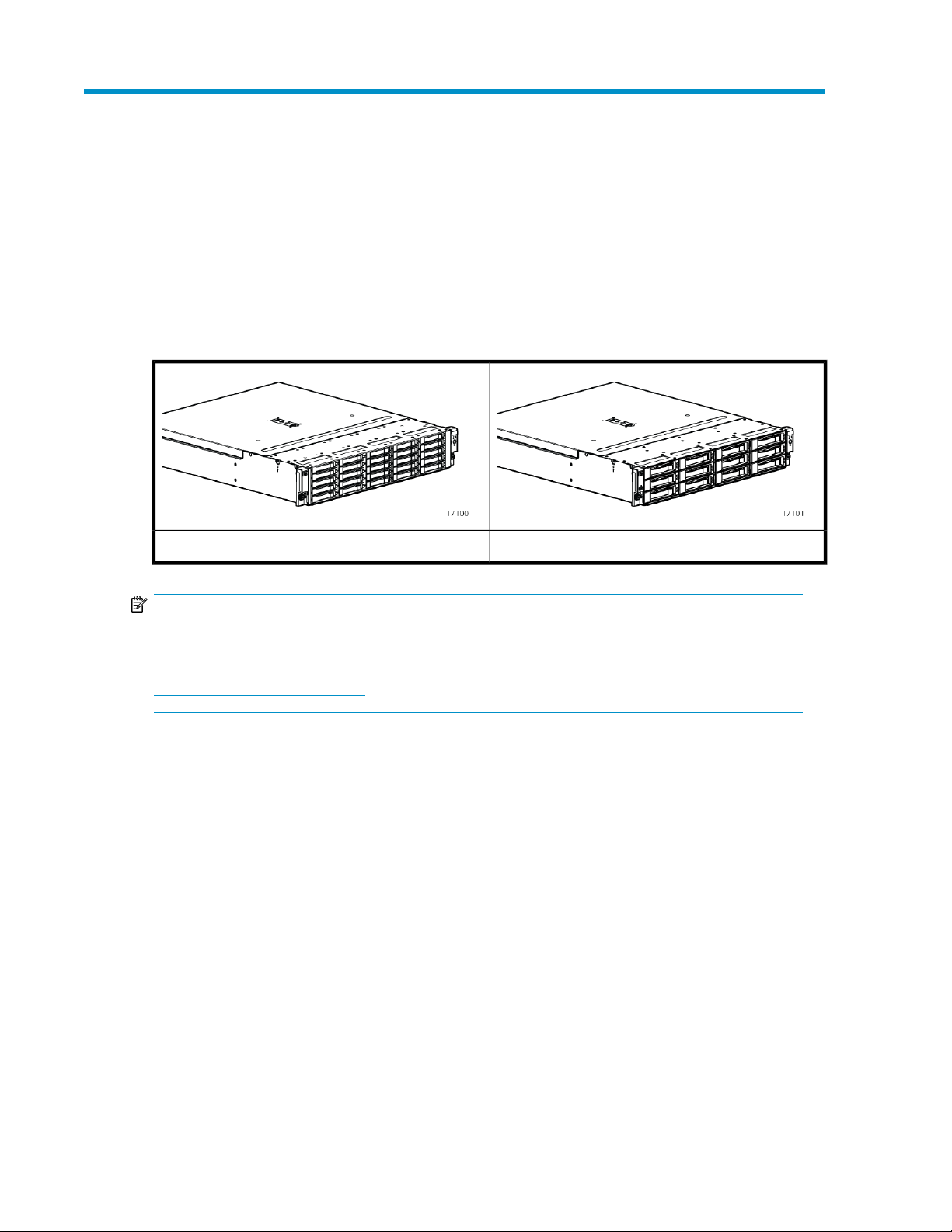
6Gb SAS disk enclosures are available in two models:
• Small Form Factor (SFF): Supports 25 SFF (2.5 inch) disk drives
• Large Form Factor (LFF): Supports 12 LFF (3.5 inch) disk drives
Large Form Factor disk enclosureSmall Form Factor disk enclosure
NOTE:
Depending on your disk enclosure model and controller installation environment, one or more disk
enclosures can be cascaded from the disk enclosure that is connected to the controller. For more
information, see the QuickSpecs for your enclosure model, available at
http://www.hp.com/go/D2000.
The enclosure and its components are detailed in the following sections:
• Small Form Factor disk enclosure chassis, page 8
• Large Form Factor disk enclosure chassis, page 9
• Disk drives, page 11
• Front status and UID module, page 12
• Power supply module, page 14
• Fan module, page 15
• I/O module, page 16
• Rear power and UID module, page 18
• SAS cables, page 20
D2600/D2700 Disk Enclosure User Guide 7
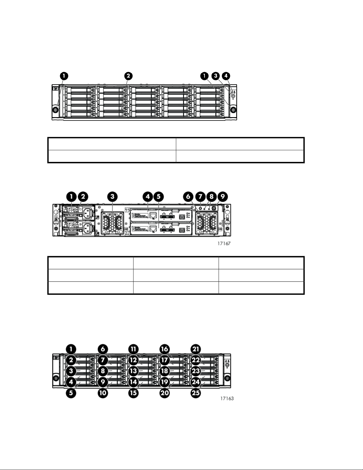
Small Form Factor disk enclosure chassis
Front view
3. UID push button and LED1. Rack-mounting thumbscrews
4. Enclosure status LEDs2. Disk drive in bay 9
Rear view
Drive bay numbering
Disk drives mount in bays on the front of the enclosure. Bays are numbered sequentially from top to
bottom and left to right. Bay numbers are indicated on the left side of each drive bay.
7. UID push button and LED4. I/O module A1. Power supply 1
8. Enclosure status LEDs5. I/O module B2. Power supply 2
9. Power push button and LED6. Fan 23. Fan 1
Hardware8
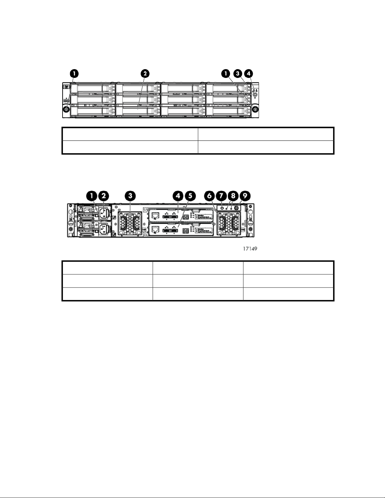
Large Form Factor disk enclosure chassis
Front view
3. UID push button and LED1. Rack-mounting thumbscrews
4. Enclosure status LEDs2. Disk drive in bay 6
Rear view
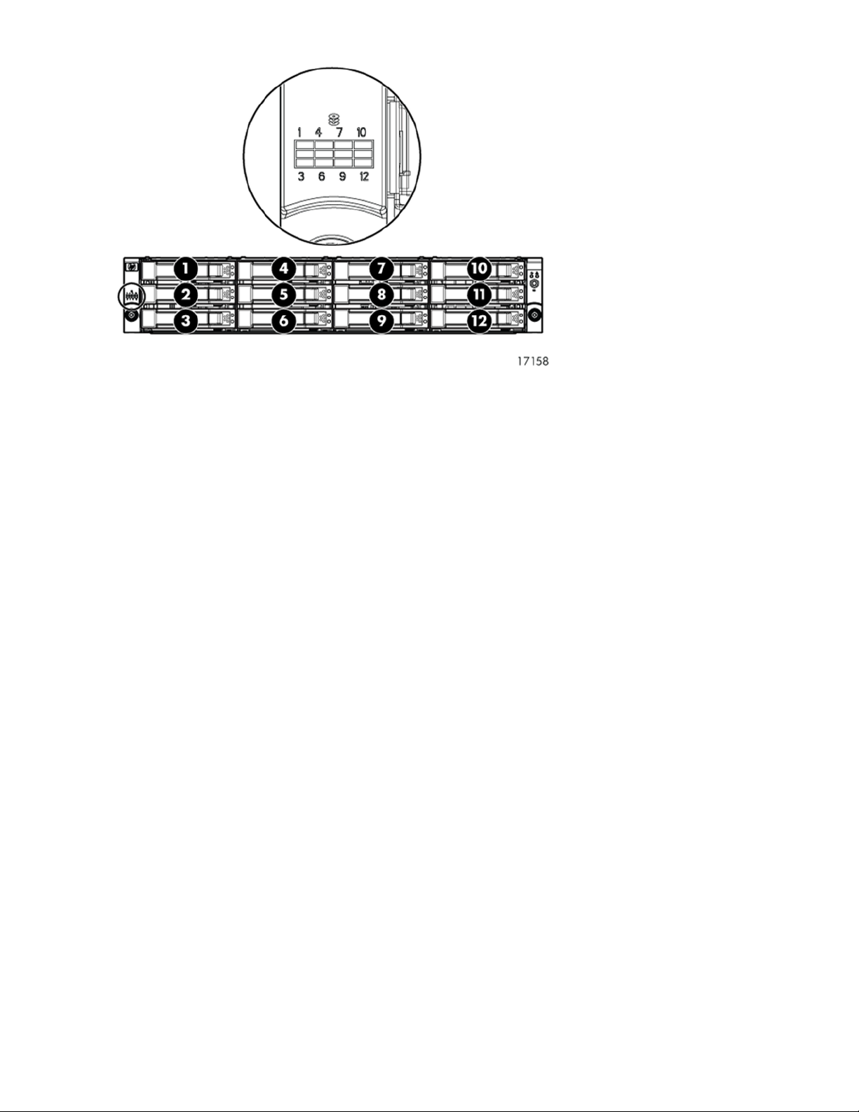
Drive bay numbering
Disk drives mount in bays on the front of the enclosure. Bays are numbered sequentially from top to
bottom and left to right. A drive-bay legend is included on the left bezel.
7. UID push button and LED4. I/O module A1. Power supply 1
8. Enclosure status LEDs5. I/O module B2. Power supply 2
9. Power push button and LED6. Fan 23. Fan 1
D2600/D2700 Disk Enclosure User Guide 9
Hardware10
Disk drives
A variety of disk drive models are supported for use, including dual-ported SAS disk drives and
single-ported SATA disk drives. For more information, see the QuickSpecs for your enclosure model,
available on the D2000 website: http://www.hp.com/go/D2000.
Disk drives are hot-pluggable.
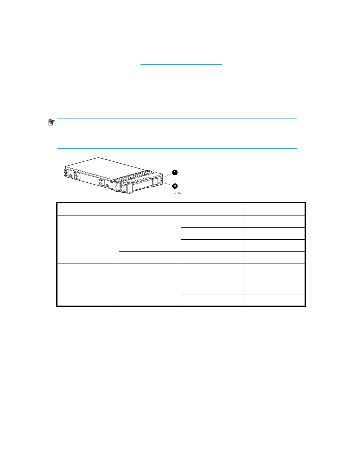
Disk drive LEDs
Two LEDs indicate drive status.
NOTE:
The following image shows a Small Form Factor (SFF) disk drive. LED patterns are the same for SFF
and LFF disk drives.
1. Locate/Fault
Disk drive blanks
To maintain the proper enclosure air flow, a disk drive or a disk drive blank must be installed in each
drive bay. The disk drive blank maintains proper airflow within the disk enclosure.
Blue
Green2. Status
Blinking
DescriptionLED statusLED colorLED
Used to locate driveSlow blinking
Used for critical locateMedium blinking
Used for reserved locateFast blinking
Drive faultSolidAmber
Drive is spinning up or
down and is not ready
Drive activityFast blinking
Ready for activitySolid
D2600/D2700 Disk Enclosure User Guide 11

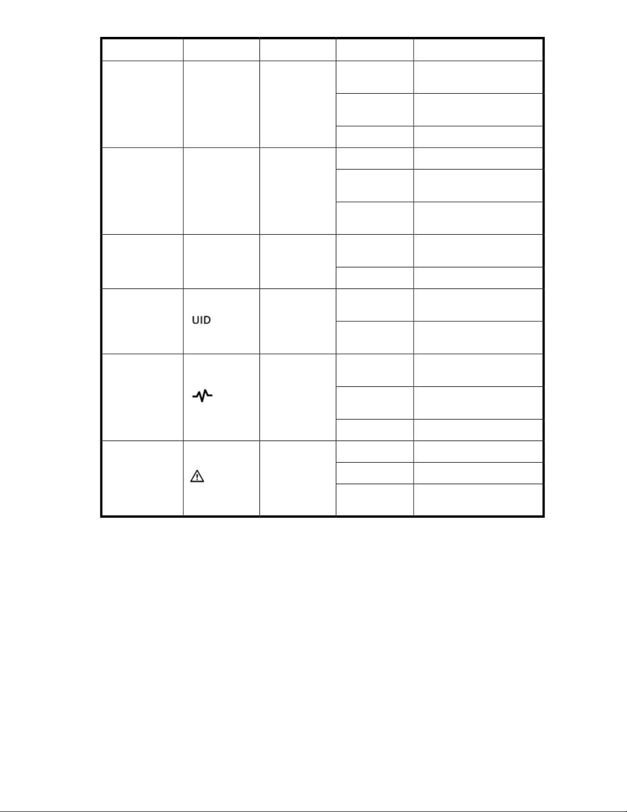
Front status and UID module
The front status and UID module includes status LEDs and a unit identification (UID) button.
Front UID module LEDs
DescriptionLED statusLED colorLED iconLED
No powerOff
Green1. Health
Amber2. Fault
Blue3. UID
Blinking
Blinking
Solid
Off
Blinking
Solid
Enclosure is starting up and
not ready, performing POST
Normal, power is onSolid
Normal, no fault conditionsOff
A fault of lesser importance
was detected in the enclosure
chassis or modules
A fault of greater importance
was detected in the enclosure
chassis or modules
Not being identified or power
is off
Unit is being identified from
the management utility
Unit is being identified from
the UID button being pushed
Hardware12

Unit identification (UID) button
The unit identification (UID) button helps locate an enclosure and its components. When the UID button
is activated, the UID on the front and rear of the enclosure are illuminated.
NOTE:
A remote session from the management utility can also illuminate the UID.
• To turn on the UID light, press the UID button. The UID light on the front and the rear of the enclosure
will illuminate solid blue. (The UID on cascaded storage enclosures are not illuminated.)
• To turn off an illuminated UID light, press the UID button. The UID light on the front and the rear
of the enclosure will turn off.
D2600/D2700 Disk Enclosure User Guide 13
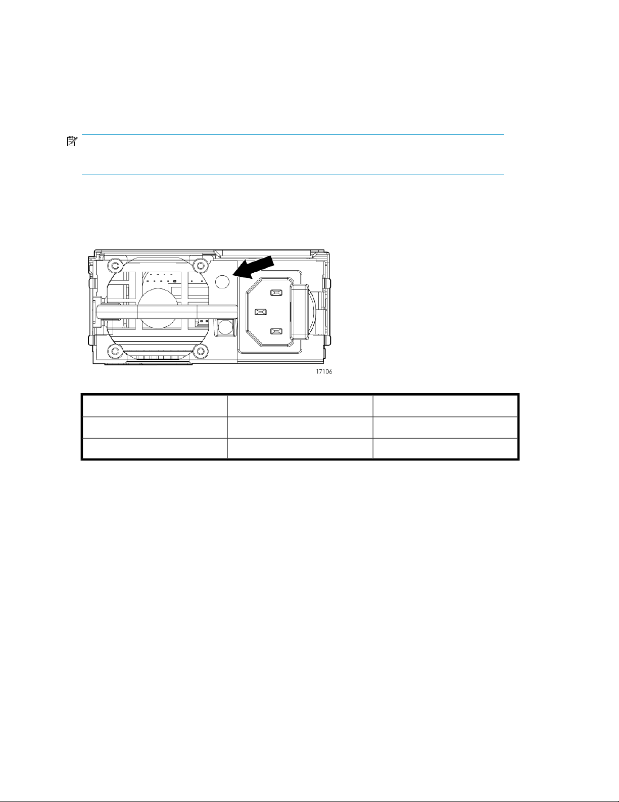
Power supply module
Two power supplies provide the necessary operating voltages to all controller enclosure components.
If one power supply fails, the remaining power supply is capable of operating the enclosure. (Replace
any failed component as soon as possible.)
NOTE:
If one of the two power supply modules fails, it can be hot-replaced.
Power supply LED
One LED provides module status information.
DescriptionLED statusLED color
No powerOffOff
Normal, no fault conditionsSolidGreen
Hardware14
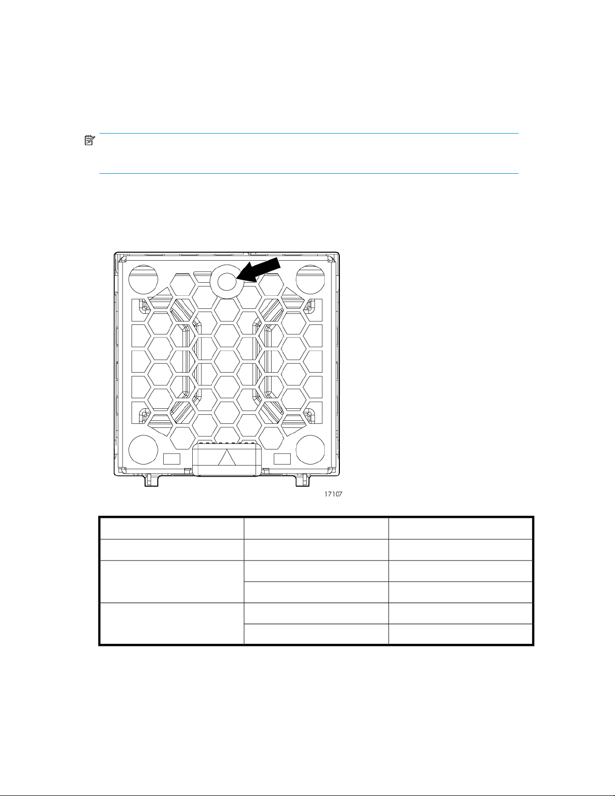
Fan module
Fan modules provide cooling necessary to maintain proper operating temperature within the controller
enclosure. If one fan fails, the remaining fan is capable of cooling the enclosure. (Replace any failed
component as soon as possible.)
NOTE:
If one of the two fan modules fail, it can be hot-replaced.
Fan module LED
One bi-color LED provides module status information.
Green
Amber
DescriptionLED statusLED color
No powerOffOff
The module is being identifiedBlinking
Normal, no fault conditionsSolid
Fault conditions detectedBlinking
Problems detecting the moduleSolid
D2600/D2700 Disk Enclosure User Guide 15
I/O module
The I/O module provides the interface between the disk enclosure and the host.
Each I/O module has two ports that can transmit and receive data for bidirectional operation.
3. SAS Port 2
I/O module LEDs
LEDs on the I/O module provide status information about each I/O port and the entire module.
Large Form Factor I/O moduleSmall Form Factor I/O module
4. Double 7–segment display1. Manufacturing diagnostic port
5. I/O module LEDs2. SAS Port 1
NOTE:
The following image illustrates LEDs on the Small Form Factor I/O module.
Hardware16
DescriptionLED statusLED colorLED iconLED
3. 7–segment display
Off
Greenn/a1. SAS Port Link The port is being identified by
Ambern/a2. SAS Port Error
n/an/a
Blue4. UID
Blinking
Blinking
Solid
Off
Off
Solid
Off
No cable, no power, or port
not connected
an application client
Healthy, active linkSolid
Normal, no errors detectedOff
Error detected by application
client
Error, fault conditions detected
on the port by the I/O module
No cable, no power, enclosure
not detected
The enclosure box numberNumber
Not being identified or no
power
Module is being identified,
from the management utility
No power or firmware malfunction
Green5. Health Enclosure is starting up and not
Amber6. Fault
Blinking
Solid
ready, performing POST
Normal, power is onSolid
Normal, no fault conditionsOff
A fault of lesser importanceBlinking
A fault of greater importance,
I/O failed to start
D2600/D2700 Disk Enclosure User Guide 17
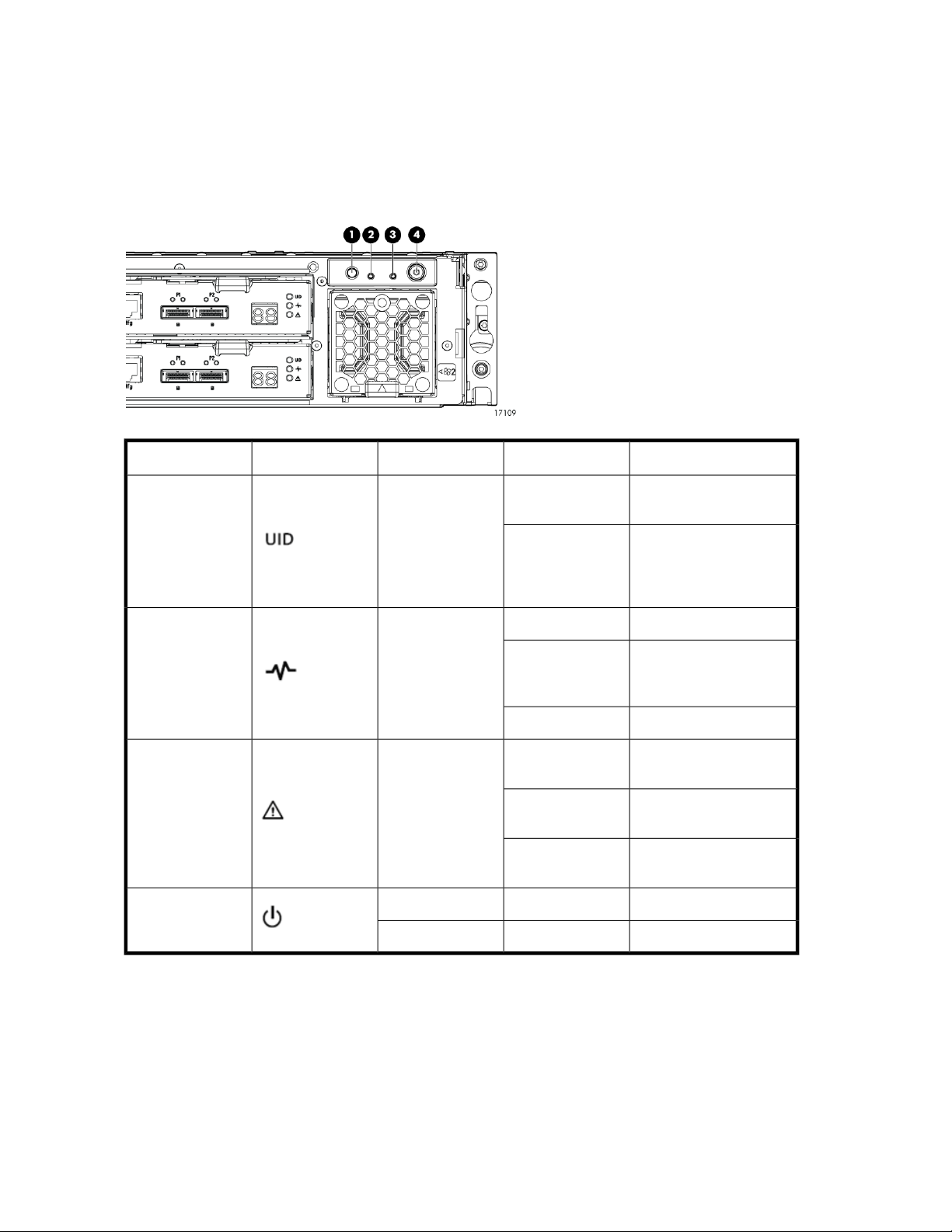
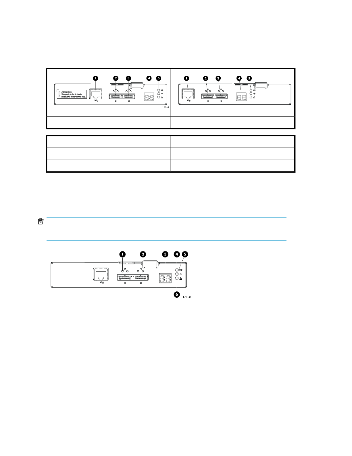
Rear power and UID module
The rear power and UID module includes status LEDs, a unit identification (UID) button, and the power
on/standby button.
Rear power and UID module LEDs
DescriptionStatusLED colorLED iconLED
4. On/Standby
Off
Blue1. UID
On
Green2. Health
Amber3. Fault
Blinking
Off
Blinking
Solid
Not being identified or no
power
Unit is being identified,
either from the UID button
being pushed or from the
management utility
No powerOff
Enclosure is starting up
and not ready, performing POST
Normal, power is onSolid
Normal, no fault conditions
A fault of lesser importance
A fault of greater importance
Power is onSolidGreen
Standby powerSolidAmber
Hardware18

Unit identification (UID) button
The unit identification (UID) button helps locate an enclosure and its components. When the UID button
is activated, the UID on the front and rear of the enclosure are illuminated.
NOTE:
A remote session from the management utility can also illuminate the UID.
• To turn on the UID light, press the UID button. The UID light on the front and the rear of the enclosure
will illuminate solid blue. (The UID on cascaded storage enclosures are not illuminated.)
• To turn off an illuminated UID light, press the UID button. The UID light on the front and the rear
of the enclosure will turn off.
Power on/standby button
The power on/standby button applies either full or partial power to the enclosure chassis.
• To initially power on the enclosure, press and hold the on/standby button for a few seconds, until
the LEDs begin to illuminate.
• To place an enclosure in standby, press and hold the on standby button for a few seconds, until
the on/standby LED changes to amber.
NOTE:
System power to the disk enclosure does not completely shut off with the power on/standby button.
The standby position removes power from most of the electronics and components, but portions of
the power supply and some internal circuitry remain active. To completely remove power from the
system, disconnect all power cords from the device.
D2600/D2700 Disk Enclosure User Guide 19
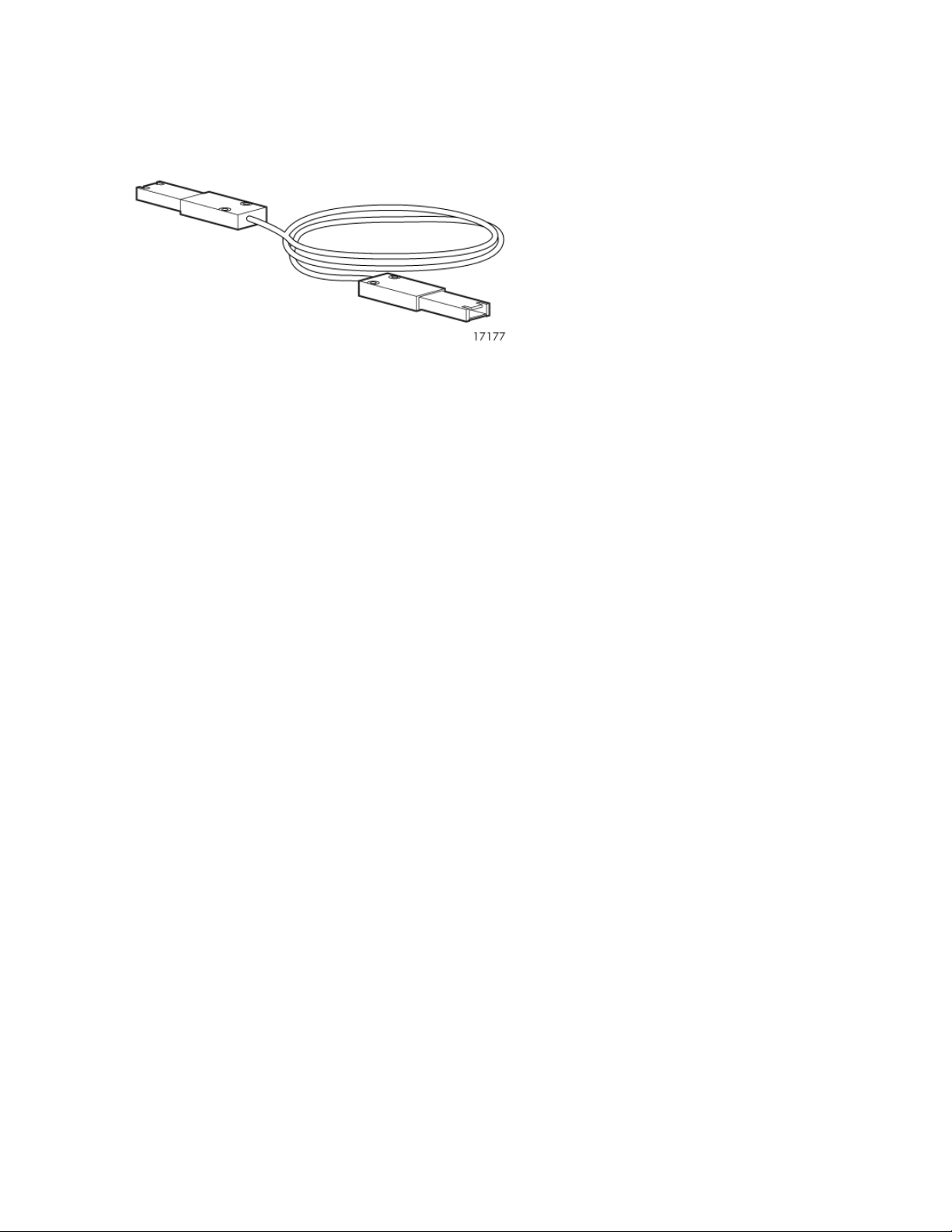
SAS cables
These disk enclosures use cables with mini-SAS connectors for connections to the controller and
cascaded disk enclosures.
Hardware20
2 Technical specifications
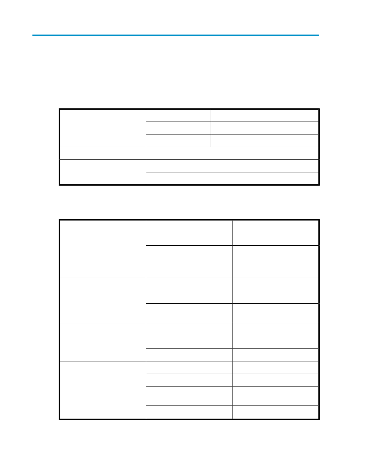
General specifications
Dimensions 45.0 cm (17.99 in)Width
17.2 kg (38 lb)Weight (base unit; no disk drives)
SFF disk drives: 24.9 kg (54.90 lb)
Weight (fully populated)
LFF disk drives: 27.2 kg (59.97 lb)
Power and environmental specifications
8.8 cm (3.47 in)Height (2U)
56.7 cm (22.3 in)Depth
Temperature range (Temperature
ratings shown are for sea level. An
altitude rating of 1°C per 300 m
(1.8°F per 1,000 ft) to 3048 m
(10,000 ft) is applicable. No direct
sunlight allowed. The upper limit
might be limited by the type and
number of options installed.)
Relative humidity (Non-operating
maximum humidity of 95% is based
on a temperature of 45°C (113°F).
Altitude maximum for storage corresponds to a pressure minimum of
70 KPa.)
Altitude (Maximum allowable altitude change rate is 457 m/min
(1500 ft/min))
Dissipation specifications are maximum values and apply to worstcase conditions at full rated power
supply load. The power/heat dissipation for your installation will vary
depending on the equipment configuration.)
Operating
Shipping
Operating
Operating
Rated input current
10°C to 35°C (50°F to 95°F)
Maximum rate of change is
10ºC/Hr (18ºF/Hr)
–40°C to 66°C (–40°F to 150°F)
Maximum rate of change is
20ºC/Hr (36ºF/Hr)
10% to 90% relative humidity (Rh)
28ºC (82.4ºF) Maximum wet bulb
temperature non-condensing
5% to 95% relative humidity (Rh)Non-operating
3048 m (10,000 ft) This value
might be limited by the type and
number of options installed.
9144 m (30,000 ft)Non-operating
100 to 240 VACRated input voltageInput power (Input Power and Heat
50 to 60 HzRated input frequency
2.68 A at 115 VAC typical, 4 A
maximum
300 WInput power (max)
D2600/D2700 Disk Enclosure User Guide 21

Technical specifications22

3 Installation
Installation overview
Installation steps include:
1. Locating Required items, page 23
2. Completing Preliminary tasks, page 24
3. Preparing the site, page 29
4. Racking the disk enclosure, page 30
5. Installing disk drives, page 33
6. Installing 6Gb SAS controllers and preparing the servers, page 35
7. Connecting cables and power cords, page 36
8. Powering on the disk enclosure, page 40
9. Verifying the operating status of the devices, page 41
Required items
Items required for installation include the following, some of which ship with the disk enclosure:
• Rack mounting kit
• Disk enclosure
• Disk drives and drive blanks
• 6Gb SAS controller
• SAS cables
• Power cables
• Access to a workstation on the server
• Access to the Internet
NOTE:
A variety of disk drives, 6Gb SAS controllers, and SAS cables are supported for use with this disk
enclosure. For more information, see the QuickSpecs for your disk enclosure model, available on the
D2000 disk enclosures website: http://www.hp.com/go/D2000.
D2600/D2700 Disk Enclosure User Guide 23

Preliminary tasks
Planning tasks include:
• Determining who will install and configure the disk enclosure, page 24
• Saving the disk enclosure website as a favorite in your browser, page 24
• Confirming support for your hardware and software components, page 24
• Signing up to automatically receive advisories, notices, and other messages, page 25
• Confirming warranty support and finding out about related services, page 25
• Gathering and recording information, page 26
• Planning the storage configuration, page 26
Determining who will install and configure the disk enclosure
Storage management experience is required to successfully install and configure this product. If you
are not familiar with installing and configuring storage array systems, HP can install this product for
you. For more information, see the Business & IT Services website: http://www.hp.com/go/services.
Different levels of assistance are available. For example, the following services might be included:
• Site inspection
• Verification of operating system patch levels
• Customized virtual disk design
• Array hardware installation and activation of optional software
• Array initialization
• Verification that the implemented solution meets your specifications
• Availability of an HP Services Storage Specialist to answer questions during the deployment process
• Verification testing to confirm product functionality and adherence to HP installation quality
standards
• On-site orientation, including highlights of basic operation and a review of documentation
Saving the disk enclosure website as a favorite in your browser
This site includes the latest information, including:
• QuickSpecs (product specifications and compatibility information)
• User documents
• Software and firmware downloads
• Support advisories and notifications
For more information, see the D2000 website: http://www.hp.com/go/D2000.
Confirming support for your hardware and software components
Specific versions of hardware, firmware, software, drivers, and other components are designed to
work together.
The QuickSpecs for your disk enclosure model provide an up-to-date list of supported servers, operating
systems, controllers, switches, and software tools. Download and review the QuickSpecs for your
enclosure model to confirm that the components you plan to use are supported for use with the disk
enclosure.
Installation24
 Loading...