

HP StorageWorks 2/64, StorageWorks Core Switch 2/64, StorageWorks SAN Director 2/128 Installation Manual
Page 1

HP StorageWorks
Core Switch 2/64 and
SAN Director 2/128
installation guide
Part number: AA–RVUSC–TE
Third edition: January 2005
Page 2

Legal and notice information
© Copyright 2004–2005 Hewlett-Packard Development Company, L.P.
Hewlett-Packard Company makes no warranty of any kind with regard to this material, including, but not limited to, the implied
warranties of merchantability and fitness for a particular purpose. Hewlett-Packard shall not be liable for errors contained herein or
for incidental or consequential damages in connection with the furnishing, performance, or use of this material.
This document contains proprietary information, which is protected by copyright. No part of this document may be photocopied,
reproduced, or translated into another language without the prior written consent of Hewlett-Packard. The information is provided
“as is” without warranty of any kind and is subject to change without notice. The only warranties for HP products and services are
set forth in the express warranty statements accompanying such products and services. Nothing herein should be construed as
constituting an additional warranty. HP shall not be liable for technical or editorial errors or omissions contained herein.
Compaq Computer Corporation is a wholly-owned subsidiary of Hewlett-Packard Company.
Microsoft,
UNIX is a registered trademark of The Open Group.
Printed in the U.S.A.
Windows, and Windows NT are U.S. registered trademarks of Microsoft Corporation.
Core Switch 2/64 and SAN Director 2/128 installation guide
Page 3

Contents
About this guide . . . . . . . . . . . . . . . . . . . . . . . . . . . . . . . . . . . . . . . 9
Intended audience . . . . . . . . . . . . . . . . . . . . . . . . . . . . . . . . . . . . . . . . . . . . . . . . . . . . . . 9
Related documentation . . . . . . . . . . . . . . . . . . . . . . . . . . . . . . . . . . . . . . . . . . . . . . . . . . . 9
Document conventions and symbols . . . . . . . . . . . . . . . . . . . . . . . . . . . . . . . . . . . . . . . . . 10
Rack stability . . . . . . . . . . . . . . . . . . . . . . . . . . . . . . . . . . . . . . . . . . . . . . . . . . . . . . . . . 11
Getting help. . . . . . . . . . . . . . . . . . . . . . . . . . . . . . . . . . . . . . . . . . . . . . . . . . . . . . . . . . 11
HP technical support . . . . . . . . . . . . . . . . . . . . . . . . . . . . . . . . . . . . . . . . . . . . . . . . . 11
HP storage web site . . . . . . . . . . . . . . . . . . . . . . . . . . . . . . . . . . . . . . . . . . . . . . . . . . 12
HP authorized reseller . . . . . . . . . . . . . . . . . . . . . . . . . . . . . . . . . . . . . . . . . . . . . . . . 12
Contents
1 Overview. . . . . . . . . . . . . . . . . . . . . . . . . . . . . . . . . . . . . . . . . 13
Core Switch 2/64 and SAN Director 2/128 models . . . . . . . . . . . . . . . . . . . . . . . . . . . . . 13
Upgrading ports . . . . . . . . . . . . . . . . . . . . . . . . . . . . . . . . . . . . . . . . . . . . . . . . . . . . . . . 14
Key features. . . . . . . . . . . . . . . . . . . . . . . . . . . . . . . . . . . . . . . . . . . . . . . . . . . . . . . . . . 14
Hardware components . . . . . . . . . . . . . . . . . . . . . . . . . . . . . . . . . . . . . . . . . . . . . . . . . . 15
High availability . . . . . . . . . . . . . . . . . . . . . . . . . . . . . . . . . . . . . . . . . . . . . . . . . . . . . . . 18
Reliability . . . . . . . . . . . . . . . . . . . . . . . . . . . . . . . . . . . . . . . . . . . . . . . . . . . . . . . . . . . 18
Serviceability . . . . . . . . . . . . . . . . . . . . . . . . . . . . . . . . . . . . . . . . . . . . . . . . . . . . . . . . . 19
Optional management features . . . . . . . . . . . . . . . . . . . . . . . . . . . . . . . . . . . . . . . . . . 19
Interoperability . . . . . . . . . . . . . . . . . . . . . . . . . . . . . . . . . . . . . . . . . . . . . . . . . . . . . 19
Security . . . . . . . . . . . . . . . . . . . . . . . . . . . . . . . . . . . . . . . . . . . . . . . . . . . . . . . . . . 20
Network manageability . . . . . . . . . . . . . . . . . . . . . . . . . . . . . . . . . . . . . . . . . . . . . . . 20
Management summary . . . . . . . . . . . . . . . . . . . . . . . . . . . . . . . . . . . . . . . . . . . . . . . . . . 20
Managing the switch . . . . . . . . . . . . . . . . . . . . . . . . . . . . . . . . . . . . . . . . . . . . . . . . . 21
Optional hardware kits . . . . . . . . . . . . . . . . . . . . . . . . . . . . . . . . . . . . . . . . . . . . . . . . . . 22
2 Installing and configuring the switch . . . . . . . . . . . . . . . . . . . . . . 25
Unpacking and verifying carton contents . . . . . . . . . . . . . . . . . . . . . . . . . . . . . . . . . . . . . . 26
Installation overview . . . . . . . . . . . . . . . . . . . . . . . . . . . . . . . . . . . . . . . . . . . . . . . . . . . . 28
Selecting an operating location . . . . . . . . . . . . . . . . . . . . . . . . . . . . . . . . . . . . . . . . . . 28
Cooling requirements . . . . . . . . . . . . . . . . . . . . . . . . . . . . . . . . . . . . . . . . . . . . . . 29
Power requirements. . . . . . . . . . . . . . . . . . . . . . . . . . . . . . . . . . . . . . . . . . . . . . . . 29
Installing the switch as a stand-alone unit . . . . . . . . . . . . . . . . . . . . . . . . . . . . . . . . . . . 30
Removing the chassis door . . . . . . . . . . . . . . . . . . . . . . . . . . . . . . . . . . . . . . . . . . . 30
Installing the switch on a flat surface . . . . . . . . . . . . . . . . . . . . . . . . . . . . . . . . . . . . 31
Installing the switch in a rack. . . . . . . . . . . . . . . . . . . . . . . . . . . . . . . . . . . . . . . . . . . . 32
Pre-installation checklist . . . . . . . . . . . . . . . . . . . . . . . . . . . . . . . . . . . . . . . . . . . . . . . 32
Items required for installation. . . . . . . . . . . . . . . . . . . . . . . . . . . . . . . . . . . . . . . . . . . . 33
Important rack mount guidelines . . . . . . . . . . . . . . . . . . . . . . . . . . . . . . . . . . . . . . . . . 34
Core Switch 2/64 and SAN Director 2/128 installation guide 3
Page 4

Installing the switch in specified racks . . . . . . . . . . . . . . . . . . . . . . . . . . . . . . . . . . . . . . 35
Attaching the rack mount shelf brackets . . . . . . . . . . . . . . . . . . . . . . . . . . . . . . . . . . . 35
Attaching the retainer nuts—for rails with square holes . . . . . . . . . . . . . . . . . . . . . . . . 37
Attaching the clip nuts—for rails with round holes . . . . . . . . . . . . . . . . . . . . . . . . . . . . 38
Attaching the upper rack mount bracket assemblies to the chassis. . . . . . . . . . . . . . . . . 38
Finalizing the rack mount procedure . . . . . . . . . . . . . . . . . . . . . . . . . . . . . . . . . . . . . 40
Sliding the switch into the rack . . . . . . . . . . . . . . . . . . . . . . . . . . . . . . . . . . . . . . 40
Securing the chassis to the rails . . . . . . . . . . . . . . . . . . . . . . . . . . . . . . . . . . . . . . 41
Reinstalling the chassis door . . . . . . . . . . . . . . . . . . . . . . . . . . . . . . . . . . . . . . . . 42
Powering on the switch . . . . . . . . . . . . . . . . . . . . . . . . . . . . . . . . . . . . . . . . . . . . . . . . . . . 43
Establishing a serial connection . . . . . . . . . . . . . . . . . . . . . . . . . . . . . . . . . . . . . . . . . . . . . 45
Manage cables . . . . . . . . . . . . . . . . . . . . . . . . . . . . . . . . . . . . . . . . . . . . . . . . . . . . . . . . 47
PID format summary . . . . . . . . . . . . . . . . . . . . . . . . . . . . . . . . . . . . . . . . . . . . . . . . . . . . . 51
Mixed fabric environment with different switch platforms . . . . . . . . . . . . . . . . . . . . . . . . . 51
Configuration overview . . . . . . . . . . . . . . . . . . . . . . . . . . . . . . . . . . . . . . . . . . . . . . . . . . . 52
Core Switch 2/64 . . . . . . . . . . . . . . . . . . . . . . . . . . . . . . . . . . . . . . . . . . . . . . . . . . . . 52
SAN Director 2/128 . . . . . . . . . . . . . . . . . . . . . . . . . . . . . . . . . . . . . . . . . . . . . . . . . . 53
Initial configuration parameters . . . . . . . . . . . . . . . . . . . . . . . . . . . . . . . . . . . . . . . . . . . . . 53
Core Switch 2/64 . . . . . . . . . . . . . . . . . . . . . . . . . . . . . . . . . . . . . . . . . . . . . . . . . . . . 53
SAN Director 2/128 . . . . . . . . . . . . . . . . . . . . . . . . . . . . . . . . . . . . . . . . . . . . . . . . . . 54
Setting up a configuration . . . . . . . . . . . . . . . . . . . . . . . . . . . . . . . . . . . . . . . . . . . . . . . . . 55
Configure IP addresses for CP cards . . . . . . . . . . . . . . . . . . . . . . . . . . . . . . . . . . . . . . . 56
Configure IP address for the switch . . . . . . . . . . . . . . . . . . . . . . . . . . . . . . . . . . . . . . . . 57
Establish an Ethernet connection . . . . . . . . . . . . . . . . . . . . . . . . . . . . . . . . . . . . . . . . . . 58
Customize a switch name . . . . . . . . . . . . . . . . . . . . . . . . . . . . . . . . . . . . . . . . . . . . . . . 59
Specify status policies . . . . . . . . . . . . . . . . . . . . . . . . . . . . . . . . . . . . . . . . . . . . . . . . . 59
Set the Domain ID . . . . . . . . . . . . . . . . . . . . . . . . . . . . . . . . . . . . . . . . . . . . . . . . . . . . 60
Connect to the fabric and configure fabric parameters . . . . . . . . . . . . . . . . . . . . . . . . . . . 60
Enable software licenses. . . . . . . . . . . . . . . . . . . . . . . . . . . . . . . . . . . . . . . . . . . . . . . . 61
Back up the configuration . . . . . . . . . . . . . . . . . . . . . . . . . . . . . . . . . . . . . . . . . . . . . . . 62
3 Operating the switch . . . . . . . . . . . . . . . . . . . . . . . . . . . . . . . . . 63
Interpreting LED activity . . . . . . . . . . . . . . . . . . . . . . . . . . . . . . . . . . . . . . . . . . . . . . . . . . . 64
16-port cards . . . . . . . . . . . . . . . . . . . . . . . . . . . . . . . . . . . . . . . . . . . . . . . . . . . . . . . 64
CP cards . . . . . . . . . . . . . . . . . . . . . . . . . . . . . . . . . . . . . . . . . . . . . . . . . . . . . . . . . . 68
Power supplies . . . . . . . . . . . . . . . . . . . . . . . . . . . . . . . . . . . . . . . . . . . . . . . . . . . . . . 71
Blower assemblies . . . . . . . . . . . . . . . . . . . . . . . . . . . . . . . . . . . . . . . . . . . . . . . . . . . . 74
WWN card . . . . . . . . . . . . . . . . . . . . . . . . . . . . . . . . . . . . . . . . . . . . . . . . . . . . . . . . 75
Diagnostics and troubleshooting overview . . . . . . . . . . . . . . . . . . . . . . . . . . . . . . . . . . . . . . 78
Obtaining chassis and component status . . . . . . . . . . . . . . . . . . . . . . . . . . . . . . . . . . . . . . . 79
Interpreting POST and boot results . . . . . . . . . . . . . . . . . . . . . . . . . . . . . . . . . . . . . . . . . . . 80
POST . . . . . . . . . . . . . . . . . . . . . . . . . . . . . . . . . . . . . . . . . . . . . . . . . . . . . . . . . . . . . 80
Boot. . . . . . . . . . . . . . . . . . . . . . . . . . . . . . . . . . . . . . . . . . . . . . . . . . . . . . . . . . . . . . 81
Diagnostics . . . . . . . . . . . . . . . . . . . . . . . . . . . . . . . . . . . . . . . . . . . . . . . . . . . . . . . . . . . 81
Troubleshooting the switch. . . . . . . . . . . . . . . . . . . . . . . . . . . . . . . . . . . . . . . . . . . . . . . . . 82
Contents4
Page 5

4 Installing FRUs . . . . . . . . . . . . . . . . . . . . . . . . . . . . . . . . . . . . . 87
Replacing the chassis door. . . . . . . . . . . . . . . . . . . . . . . . . . . . . . . . . . . . . . . . . . . . . . . . 87
Replacing the cable management tray. . . . . . . . . . . . . . . . . . . . . . . . . . . . . . . . . . . . . . . . 88
Replacing the cable guides (pillars). . . . . . . . . . . . . . . . . . . . . . . . . . . . . . . . . . . . . . . . . . 90
Replacing a 16-port card and filler panel . . . . . . . . . . . . . . . . . . . . . . . . . . . . . . . . . . . . . 90
Preliminary steps . . . . . . . . . . . . . . . . . . . . . . . . . . . . . . . . . . . . . . . . . . . . . . . . . . . . 90
Replacing a 16-port card . . . . . . . . . . . . . . . . . . . . . . . . . . . . . . . . . . . . . . . . . . . . . . 91
Removing the existing16-port card . . . . . . . . . . . . . . . . . . . . . . . . . . . . . . . . . . . . . . . . 93
Removing a filler panel. . . . . . . . . . . . . . . . . . . . . . . . . . . . . . . . . . . . . . . . . . . . . . . . 94
Installing a 16-port card . . . . . . . . . . . . . . . . . . . . . . . . . . . . . . . . . . . . . . . . . . . . . . . 95
Installing a filler panel . . . . . . . . . . . . . . . . . . . . . . . . . . . . . . . . . . . . . . . . . . . . . . . . 97
Replacing a CP card . . . . . . . . . . . . . . . . . . . . . . . . . . . . . . . . . . . . . . . . . . . . . . . . . . . . 97
Identifying a failed CP Card. . . . . . . . . . . . . . . . . . . . . . . . . . . . . . . . . . . . . . . . . 100
Recording critical switch information . . . . . . . . . . . . . . . . . . . . . . . . . . . . . . . . . . . 100
Removing a CP card . . . . . . . . . . . . . . . . . . . . . . . . . . . . . . . . . . . . . . . . . . . . . . 103
Installing a CP card. . . . . . . . . . . . . . . . . . . . . . . . . . . . . . . . . . . . . . . . . . . . . . . 104
Verifying operation of the new CP card . . . . . . . . . . . . . . . . . . . . . . . . . . . . . . . . . 105
Replacing a power supply and filler panel. . . . . . . . . . . . . . . . . . . . . . . . . . . . . . . . . . . . 110
Replacing a power supply . . . . . . . . . . . . . . . . . . . . . . . . . . . . . . . . . . . . . . . . . . 111
Replacing a blower assembly. . . . . . . . . . . . . . . . . . . . . . . . . . . . . . . . . . . . . . . . . . . . . 113
Replacing the WWN bezel and card . . . . . . . . . . . . . . . . . . . . . . . . . . . . . . . . . . . . . . . 115
Identifying a failed WWN card. . . . . . . . . . . . . . . . . . . . . . . . . . . . . . . . . . . . . . . . . 115
Replacing a WWN card . . . . . . . . . . . . . . . . . . . . . . . . . . . . . . . . . . . . . . . . . . . . . 117
Installing a WWN card . . . . . . . . . . . . . . . . . . . . . . . . . . . . . . . . . . . . . . . . . . . . . . 121
Replacing the WWN bezel. . . . . . . . . . . . . . . . . . . . . . . . . . . . . . . . . . . . . . . . . . . . 122
5 Setting up and installing modems . . . . . . . . . . . . . . . . . . . . . . . 123
Using high-availability connectivity . . . . . . . . . . . . . . . . . . . . . . . . . . . . . . . . . . . . . . . . . 123
Connecting modems . . . . . . . . . . . . . . . . . . . . . . . . . . . . . . . . . . . . . . . . . . . . . . . . . . . 125
Setting up a remote modem system . . . . . . . . . . . . . . . . . . . . . . . . . . . . . . . . . . . . . . . . . 126
Verifying the modem connection. . . . . . . . . . . . . . . . . . . . . . . . . . . . . . . . . . . . . . . . . . . 127
6 Running routine operations. . . . . . . . . . . . . . . . . . . . . . . . . . . . 131
Backing up system configuration settings . . . . . . . . . . . . . . . . . . . . . . . . . . . . . . . . . . . . . 131
Restoring the system configuration settings . . . . . . . . . . . . . . . . . . . . . . . . . . . . . . . . . . . . 132
Upgrading firmware . . . . . . . . . . . . . . . . . . . . . . . . . . . . . . . . . . . . . . . . . . . . . . . . . . . 132
Verifying optional software licenses . . . . . . . . . . . . . . . . . . . . . . . . . . . . . . . . . . . . . . . . 133
Enabling licensed features . . . . . . . . . . . . . . . . . . . . . . . . . . . . . . . . . . . . . . . . . . . . 133
A Technical specifications . . . . . . . . . . . . . . . . . . . . . . . . . . . . . . 135
System architecture . . . . . . . . . . . . . . . . . . . . . . . . . . . . . . . . . . . . . . . . . . . . . . . . . . . . 135
System size and weight . . . . . . . . . . . . . . . . . . . . . . . . . . . . . . . . . . . . . . . . . . . . . . . . . 137
System FRU weights . . . . . . . . . . . . . . . . . . . . . . . . . . . . . . . . . . . . . . . . . . . . . . . . . . . 137
Facility requirements . . . . . . . . . . . . . . . . . . . . . . . . . . . . . . . . . . . . . . . . . . . . . . . . . . . 138
Power specifications . . . . . . . . . . . . . . . . . . . . . . . . . . . . . . . . . . . . . . . . . . . . . . . . . . . 138
Power cords. . . . . . . . . . . . . . . . . . . . . . . . . . . . . . . . . . . . . . . . . . . . . . . . . . . . . . . . . 140
Core Switch 2/64 and SAN Director 2/128 installation guide 5
Page 6

Fibre Channel port specifications . . . . . . . . . . . . . . . . . . . . . . . . . . . . . . . . . . . . . . . . . . . 143
CP card specifications. . . . . . . . . . . . . . . . . . . . . . . . . . . . . . . . . . . . . . . . . . . . . . . . . . . 143
Memory specifications . . . . . . . . . . . . . . . . . . . . . . . . . . . . . . . . . . . . . . . . . . . . . . . . 143
Battery specifications . . . . . . . . . . . . . . . . . . . . . . . . . . . . . . . . . . . . . . . . . . . . . . . . . 144
Terminal serial port specifications . . . . . . . . . . . . . . . . . . . . . . . . . . . . . . . . . . . . . . . . 144
Modem serial port specifications . . . . . . . . . . . . . . . . . . . . . . . . . . . . . . . . . . . . . . . . . 145
B Electrostatic discharge . . . . . . . . . . . . . . . . . . . . . . . . . . . . . . . 147
Grounding methods . . . . . . . . . . . . . . . . . . . . . . . . . . . . . . . . . . . . . . . . . . . . . . . . . . . . 147
C Regulatory compliance notices . . . . . . . . . . . . . . . . . . . . . . . . . 149
FCC EMC statement (USA) . . . . . . . . . . . . . . . . . . . . . . . . . . . . . . . . . . . . . . . . . . . . . . . 149
EMC statement (Canada) . . . . . . . . . . . . . . . . . . . . . . . . . . . . . . . . . . . . . . . . . . . . . . . . 149
EMC statement (European Union) . . . . . . . . . . . . . . . . . . . . . . . . . . . . . . . . . . . . . . . . . . . 149
Germany noise declaration . . . . . . . . . . . . . . . . . . . . . . . . . . . . . . . . . . . . . . . . . . . . . . . 150
VCCI EMC statement (Japan) . . . . . . . . . . . . . . . . . . . . . . . . . . . . . . . . . . . . . . . . . . . . . . 150
Power cord statement (Japan). . . . . . . . . . . . . . . . . . . . . . . . . . . . . . . . . . . . . . . . . . . . . . 150
RRL EMC statement (Korea) . . . . . . . . . . . . . . . . . . . . . . . . . . . . . . . . . . . . . . . . . . . . . . . 151
Laser safety . . . . . . . . . . . . . . . . . . . . . . . . . . . . . . . . . . . . . . . . . . . . . . . . . . . . . . . . . . 151
Battery replacement notice. . . . . . . . . . . . . . . . . . . . . . . . . . . . . . . . . . . . . . . . . . . . . . . . 152
Glossary . . . . . . . . . . . . . . . . . . . . . . . . . . . . . . . . . . . . . . . . . . 153
Index . . . . . . . . . . . . . . . . . . . . . . . . . . . . . . . . . . . . . . . . . . . . 161
Figures
1 Core Switch 2/64 and SAN Director 2/128 (port side). . . . . . . . . . . . . . . . . . . . . . . . . 16
2 Core Switch 2/64 and SAN Director 2/128 (nonport side) . . . . . . . . . . . . . . . . . . . . . . 17
3 Carton contents . . . . . . . . . . . . . . . . . . . . . . . . . . . . . . . . . . . . . . . . . . . . . . . . . . . . . 26
4 Sequence for detaching the chassis door from the hinges . . . . . . . . . . . . . . . . . . . . . . . . 30
5 Installing the left and right rack mount shelf brackets . . . . . . . . . . . . . . . . . . . . . . . . . . . 36
6 Installing the retainer nuts on the rails. . . . . . . . . . . . . . . . . . . . . . . . . . . . . . . . . . . . . . 37
7 Attaching the left and right flat upper rack mount brackets . . . . . . . . . . . . . . . . . . . . . . . 39
8 Attaching L-shaped brackets to rails . . . . . . . . . . . . . . . . . . . . . . . . . . . . . . . . . . . . . . . 40
9 Attaching the upper rack mount bracket to the L-shaped brackets. . . . . . . . . . . . . . . . . . . 41
10 Securing the chassis port side to rack rails . . . . . . . . . . . . . . . . . . . . . . . . . . . . . . . . . . 42
11 ON/OFF switch for a 16-port card . . . . . . . . . . . . . . . . . . . . . . . . . . . . . . . . . . . . . . . 43
12 AC panel and power cord retainers. . . . . . . . . . . . . . . . . . . . . . . . . . . . . . . . . . . . . . . 44
13 Cable guide (pillar) . . . . . . . . . . . . . . . . . . . . . . . . . . . . . . . . . . . . . . . . . . . . . . . . . . 48
14 Effective cable management (Director 2/128 shown). . . . . . . . . . . . . . . . . . . . . . . . . . . 50
15 Front of 16-port card . . . . . . . . . . . . . . . . . . . . . . . . . . . . . . . . . . . . . . . . . . . . . . . . . 65
16 Front of CP card . . . . . . . . . . . . . . . . . . . . . . . . . . . . . . . . . . . . . . . . . . . . . . . . . . . . 69
17 Power supply LEDs. . . . . . . . . . . . . . . . . . . . . . . . . . . . . . . . . . . . . . . . . . . . . . . . . . . 72
18 Blower assembly LEDs . . . . . . . . . . . . . . . . . . . . . . . . . . . . . . . . . . . . . . . . . . . . . . . . 74
19 WWN bezel LEDs . . . . . . . . . . . . . . . . . . . . . . . . . . . . . . . . . . . . . . . . . . . . . . . . . . . 77
20 Upper door hinge . . . . . . . . . . . . . . . . . . . . . . . . . . . . . . . . . . . . . . . . . . . . . . . . . . . 88
Contents6
Page 7

21 Cable management tray . . . . . . . . . . . . . . . . . . . . . . . . . . . . . . . . . . . . . . . . . . . . . . . 89
22 16-port card removal and replacement. . . . . . . . . . . . . . . . . . . . . . . . . . . . . . . . . . . . . 92
23 Removing and replacing a filler panel . . . . . . . . . . . . . . . . . . . . . . . . . . . . . . . . . . . . . 94
24 Card guides inside each card slot . . . . . . . . . . . . . . . . . . . . . . . . . . . . . . . . . . . . . . . . 96
25 CP card removal and replacement . . . . . . . . . . . . . . . . . . . . . . . . . . . . . . . . . . . . . . . . 99
26 Power supply removal and replacement . . . . . . . . . . . . . . . . . . . . . . . . . . . . . . . . . . . 112
27 Blower assembly removal and replacement . . . . . . . . . . . . . . . . . . . . . . . . . . . . . . . . . 114
28 WWN bezel and card removal and replacement . . . . . . . . . . . . . . . . . . . . . . . . . . . . 121
29 Two modems attached for high availability . . . . . . . . . . . . . . . . . . . . . . . . . . . . . . . . . 124
30 Remote modem setup . . . . . . . . . . . . . . . . . . . . . . . . . . . . . . . . . . . . . . . . . . . . . . . . 126
Tables
1 Document conventions . . . . . . . . . . . . . . . . . . . . . . . . . . . . . . . . . . . . . . . . . . . . . . . . 10
2 Management options for Core Switch 2/64 and SAN Director 2/128 . . . . . . . . . . . . . . 21
3 Core Switch 2/64 and SAN Director 2/128 orderable hardware. . . . . . . . . . . . . . . . . . 22
4 Carton contents checklist. . . . . . . . . . . . . . . . . . . . . . . . . . . . . . . . . . . . . . . . . . . . . . . 27
5 Core Switch 2/64 default parameters . . . . . . . . . . . . . . . . . . . . . . . . . . . . . . . . . . . . . 54
6 Director 2/128 default parameters . . . . . . . . . . . . . . . . . . . . . . . . . . . . . . . . . . . . . . . 55
7 16-port card LED patterns . . . . . . . . . . . . . . . . . . . . . . . . . . . . . . . . . . . . . . . . . . . . . . 66
8 CP card LED patterns . . . . . . . . . . . . . . . . . . . . . . . . . . . . . . . . . . . . . . . . . . . . . . . . . 70
9 Power supply LED patterns . . . . . . . . . . . . . . . . . . . . . . . . . . . . . . . . . . . . . . . . . . . . . 73
10 Blower assembly LED patterns . . . . . . . . . . . . . . . . . . . . . . . . . . . . . . . . . . . . . . . . . . . 75
11 Data stored on the WWN card . . . . . . . . . . . . . . . . . . . . . . . . . . . . . . . . . . . . . . . . . . 76
12 Messages that can indicate WWN card failure . . . . . . . . . . . . . . . . . . . . . . . . . . . . . . . 76
13 WWN bezel LED patterns . . . . . . . . . . . . . . . . . . . . . . . . . . . . . . . . . . . . . . . . . . . . . 77
14 Environmental status and maintenance commands . . . . . . . . . . . . . . . . . . . . . . . . . . . . . 79
15 Troubleshooting the switch . . . . . . . . . . . . . . . . . . . . . . . . . . . . . . . . . . . . . . . . . . . . . 82
16 Data stored on the WWN card . . . . . . . . . . . . . . . . . . . . . . . . . . . . . . . . . . . . . . . . . 116
17 Messages that might indicate a WWN card failure . . . . . . . . . . . . . . . . . . . . . . . . . . . 116
18 Terminal emulator configuration settings . . . . . . . . . . . . . . . . . . . . . . . . . . . . . . . . . . . 127
19 Core Switch 2/64 and SAN Director 2/128 system specifications . . . . . . . . . . . . . . . . 135
20 System size and weight . . . . . . . . . . . . . . . . . . . . . . . . . . . . . . . . . . . . . . . . . . . . . . 137
21 FRU weights . . . . . . . . . . . . . . . . . . . . . . . . . . . . . . . . . . . . . . . . . . . . . . . . . . . . . . 137
22 Power specifications. . . . . . . . . . . . . . . . . . . . . . . . . . . . . . . . . . . . . . . . . . . . . . . . . 138
23 Power cord types (international). . . . . . . . . . . . . . . . . . . . . . . . . . . . . . . . . . . . . . . . . 140
24 Terminal serial port pinouts . . . . . . . . . . . . . . . . . . . . . . . . . . . . . . . . . . . . . . . . . . . . 144
25 Modem serial port pinouts . . . . . . . . . . . . . . . . . . . . . . . . . . . . . . . . . . . . . . . . . . . . 145
Core Switch 2/64 and SAN Director 2/128 installation guide 7
Page 8

Contents8
Page 9

About this guide
This installation guide provides information to help you:
• Set up and configure the HP StorageWorks Core Switch 2/64 (Core Switch 2/64) and HP
StorageWorks SAN Director 2/128 (SAN Director 2/128)
• Maintain and operate the switches
• Contact technical support for additional assistance
Intended audience
This guide is intended for system administrators and technicians who are experienced with the
following:
• HP StorageWorks Fibre Channel Storage Area Network (SAN) switches
• Fabric Operating System
Related documentation
Documentation, including white papers and best practices documents, is available on the HP
website:
http://www.hp.com/country/us/eng/prodserv/storage.html
To access current Fabric OS related documents:
1. Locate the Networked storage section of the web page.
2. Under Networked storage, go to the By type subsection.
3. Click SAN infrastructure.
The SAN infrastructure page displays.
4. Locate the Fibre Channel Switches section.
5. Locate the B-Series Fabric subsection, and then go to the Enterprise Class subsection.
6. To access version documents (such as this document), select SAN Director 2/128 & SAN
Director 2/128 power pack or Core Switch 2/64 & Core Switch 2/64 power pack.
The switch overview page displays.
7. Go to the Product Information section, located on the right side of the web page.
Core Switch 2/64 and SAN Director 2/128 installation guide 9
Page 10

8. Click Technical documents.
9. Follow the onscreen instructions to download the applicable documents.
Document conventions and symbols
Table 1 Document conventions
Convention Element
Medium blue text: Figure 1 Cross-reference links
Bold Menu items, buttons, keys, tabs, and user input in a graphical
interface
Italics Text emphasis
Monospace font Command-line user input, commands, code, device instances,
file and directory names, and system responses (output and
messages)
Monospace, italic font Command-line and code variables
Medium blue, underlined sans serif
font text (http://www.hp.com
)
Web site addresses
WARNING! Indicates that failure to follow directions could result in bodily harm or death.
CAUTION: Indicates that failure to follow directions could result in damage to equipment or
data.
IMPORTANT: Provides clarifying information or specific instructions.
!
NOTE: Provides additional information.
About this guide10
Page 11

TIP: Provides helpful hints and shortcuts.
Rack stability
WARNING! To reduce the risk of personal injury or damage to equipment:
• Extend leveling jacks to the floor.
• Ensure that the full weight of the rack rests on the leveling jacks.
• Install stabilizing feet on the rack.
• In multiple-rack installations, secure racks together.
• Extend only one rack component at a time. Racks may become unstable if more than one
component is extended.
Getting help
If you still have a question after reading this guide, contact an HP authorized service provider
or access our web site at
HP technical support
Telephone numbers for worldwide technical support are listed on the following HP web site:
http://www.hp.com/support/
NOTE: For continuous quality improvement, calls may be recorded or monitored.
Be sure to have the following information available before calling:
• Technical support registration number (if applicable)
• Product serial numbers
• Product model names and numbers
• Applicable error messages
http://www.hp.com
.
. From this web site, select the country of origin.
Core Switch 2/64 and SAN Director 2/128 installation guide 11
Page 12

• Operating system type and revision level
• Detailed, specific questions
HP storage web site
The HP storage web site has the latest information on this product, as well as the latest drivers:
http://www.hp.com/country/us/eng/prodserv/storage.html
appropriate product or solution.
HP authorized reseller
For the name of your nearest HP authorized reseller:
• In the United States, call 1-800-345-1518
• In Canada, call 1-800-263-5868
. From this web site, select the
• Elsewhere, see the HP web site for locations and telephone numbers:
http://www.hp.com
.
About this guide12
Page 13

1Overview
This chapter provides the following topics:
• Core Switch 2/64 and SAN Director 2/128 models, page 13
• Upgrading ports, page 14
• Key features, page 14
• Hardware components, page 15
• High availability, page 18
• Reliability, page 18
• Serviceability, page 19
• Management summary, page 20
• Optional hardware kits, page 22
Core Switch 2/64 and SAN Director 2/128
models
The Core Switch 2/64 and SAN Director 2/128 include the following configurations:
• Basic models— Ship with 32 ports installed and include Advanced Zoning and Advanced
Web Tools as standard software components.
• Power Pack models—Ship with 32 ports installed and include Zoning and Advanced Web
Tools as standard software components. These models also include licenses for all optional
management tools:
•Fabric Watch
• Advanced Performance Monitoring
•ISL Trunking
• Extended Fabric
•Remote Switch
13Core Switch 2/64 and SAN Director 2/128 installation guide
Page 14

Upgrading ports
The Core Switch 2/64 and SAN Director 2/128 are available with 32 ports (0 through 31)
installed and activated. To install additional ports, contact your HP representative to purchase
a 16-port Upgrade module. Then, see the following sections for instructions on installing the
16-port card module:
• Removing a filler panel, page 94
• Installing a 16-port card, page 95.
Key features
The Core Switch 2/64 and SAN Director 2/128 represent the next generation of advanced
Fibre Channel Director models used to interconnect storage devices, hosts, and servers
intelligently in a Storage Area Network (SAN). HP StorageWorks director-class switches deliver
performance, scalability, flexibility, functionality, reliability, and availability.
Key features include the following:
• 64 ports in a single chassis for the Core Switch 2/64.
• 128 ports in a single chassis for the SAN Director 2/128.
• High-availability platform for mission-critical SAN-designed applications.
• Dual, redundant Control Processors (CP) provide high availability and enable nondisruptive
software upgrades.
• Nonblocking architecture enables all ports to operate at full 2 Gb speed simultaneously.
• Universal ports self-configure as E-ports, F-ports, or FL-ports.
• Small form-factor pluggable (SFP) optical transceivers support any combination of short
wavelength (SWL), long wavelength (LWL), and extended long wavelength (ELWL) optical
media on a single switch module (the 16-port card).
• Forward and backward compatibility with HP StorageWorks switches.
• High availability redundant design, extensive diagnostics, and system monitoring
capabilities integrated with Fabric OS management tools deliver unprecedented reliability,
availability, and serviceability (RAS).
• Support for 1- and 2-Gb/s autosensing Fibre Channel ports (trunking technology groups up
to four ports together to create high-performance 8 Gb/s ISL trunks between switches).
Overview14
Page 15

Hardware components
The Core Switch 2/64 and SAN Director 2/128 feature a modular and scalable
mechanical construction that allows a wide range of flexibility in switch installation, fabric
design, and maintenance.
The modular chassis consists of the following:
• Two slots for control processor (CP) cards (slots 5 and 6):
• A single active CP card can control all ports in the chassis.
• The standby CP card assumes control of the switch if the active CP fails.
• Modular hot-swappable field replaceable units (FRUs):
• Up to eight I/O cards
•Two CP cards
• Small form-factor pluggable (SFP) optical transceivers
• Three blower assemblies
• Four power supplies
• Cables
• Support for mounting the chassis with the port side facing the air-intake aisle if adequate
cooling is provided
• Easy cable management using a cable management tray and cable guides (pillars)
• Constant intake and FAN temperature monitoring
• World Wide Name (WWN) card on the nonport side, to maintain chassis-specific
information such as WWNs, IP addresses, and summary status information of each card
(16-port and CP) and power supply through LEDs
Figure 1 shows the port side of the Core Switch 2/64 and the SAN Director 2/128.
15Core Switch 2/64 and SAN Director 2/128 installation guide
Page 16

Exhaust
Vent
1 2 3 4 5 6 7 8 9 10
Power
Supply
Filler
Panel
ON/OFF Switch
(in "ON" position)
ON/OFF Switch
(in "OFF" position)
CP Card
16-Port
Card
Grounding
Strap
Connector
scale:
3/16" = 1"
AC Power
Switch
!
15
15
d
d
14
14
c
c
13
13
b
b
12
12
a
a
11
11
d
d
10
10
c
c
9
9
b
b
8
8
a
a
7
7
d
d
6
6
c
c
5
5
b
b
4
4
a
a
3
3
d
d
2
2
c
c
1
1
b
b
0
0
a
a
15
15
d
d
14
14
c
c
13
13
b
b
12
12
a
a
11
11
d
d
10
10
c
c
9
9
b
b
8
8
a
a
7
7
d
d
6
6
c
c
5
5
b
b
4
4
a
a
3
3
d
d
2
2
c
c
1
1
b
b
0
0
a
a
POWER SUPPLY 1&3 POWER SUPPLY 2&4
200-240 VAC 12A 50-60 Hz
!
!
IOIOIRS -232
IOIOIRS -232
Link
Link
10/100Mb/s
10/100Mb/s
ActiveCP
ActiveCP
200-240 VAC 12A 50-60 Hz
!
!
!
AC Power
Connector
!
!
15
15
d
14
14
c
13
13
b
12
12
a
11
11
d
10
10
c
9
9
b
8
8
a
7
7
d
6
6
c
5
5
b
4
4
a
3
3
d
2
2
c
1
1
b
0
0
a
AC Power
Connector
d
c
b
a
d
c
b
a
d
c
b
a
d
c
b
a
AC Power
(for Power Supply1&3) (for Power Supply2&4)
POWER SUPPLY 4
POWER SUPPLY 3
!
!
POWER SUPPLY 2
!
!
POWER SUPPLY 1
Switch
Card
Slot
Filler
Panel
Power
Supply
#2
Power
Supply
#1
Cable
Management
Tray
2.001
Figure 1 Core Switch 2/64 and SAN Director 2/128 (port side)
NOTE: Card slots are numbered 1 through 10 (left to right). Slots 1–4 and 7–10
accommodate the 16-port cards, and slots 5-6 accommodate the CP cards.
Overview16
Page 17

Figure 2 shows the nonport side of the Core Switch 2/64 and SAN Director 2/128.
Port Card and
CP Card LEDs
WWN
Bezel
Power Supply
LEDs
10 pwr4
987654321
pwr3
pwr2
pwr1
Blower
Power
LED
Blower
Fault
LED
Blower
Handle
Blower
Assembly
#3
scale:
Blower
3/16" = 1"
Assembly #1
Figure 2 Core Switch 2/64 and SAN Director 2/128 (nonport side)
Blower
Assembly #2
2.006
17Core Switch 2/64 and SAN Director 2/128 installation guide
Page 18

High availability
The following features contribute to the Core Switch 2/64 and SAN Director 2/128
high-availability design:
• Redundant, hot-swappable components
• Redundant power and cooling subsystems
• Enhanced data integrity on all data paths
• Fabric Shortest Path First (FSPF) rerouting around failed links
• Integration with SNMP managers
• Automatic control processor failover
• Nondisruptive hot software code loads and activation
• Easy configuration, save, and restore
The high-availability software architecture of the Core Switch 2/64 and the SAN
Director 2/128 provides a common framework for all applications that reside on the system,
allowing global and local states to be maintained enough to manage any component failure.
High-availability elements consist of the High Availability Manager, the heartbeat, the
fault/health framework, the replicated database, initialization, and software upgrade.
The High Availability Manager controls access to the standby control processor, facilitates
software upgrades, prevents extraneous switchover activity, closes and flushes streams as
needed, provides flow control and message buffering, and supports a centralized active and
standby state.
Reliability
The Core Switch 2/64 and the SAN Director 2/128 use the following error detection and
correction mechanisms to ensure the reliability of all data inside the chassis:
• Power-on self test (POST)
• Error Detection and Fault Isolation (EDFI), such as cyclic redundancy checking (CRC), parity
checking, checksum, and illegal address checking
Overview18
Page 19

• Dual control processors that enable hot, nondisruptive fast firmware upgrades
Each control processor contains two serial ports and one Ethernet port. Offline control
processor diagnostics and remote diagnostics simplify troubleshooting. The standby control
processor continuously runs diagnostics to ensure it is operational, should a failover be
necessary.
2
• I
C monitoring and control, used between Integrated Circuits (IC) to monitor how they are
working
Serviceability
The Core Switch 2/64 and the SAN Director 2/128 provide the following features to enhance
and ensure serviceability:
• Modular design with hot-swappable components
• Redundant flash memory that stores two firmware images per control processor
• Extensive diagnostics and status reporting, along with a serial port to support an external,
country-specific modem for remote diagnostics and status monitoring
• Nonvolatile random-access memory (NVRAM), containing the HP serial number,
manufacturer’s serial number, revision information, and part number information
• Background health-check daemon
• Memory scrubber, self test, and bus ping to determine if a bus is not functioning
• Watchdog timers
• Status LEDs
• Predictive diagnostics analysis through Fabric Watch
• SNMP integration with higher-layer managers
Optional management features
Refer to the HP StorageWorks release notes for the Fabric OS running on your switch to get a
complete list of management and optional software features enabled on the switch.
Interoperability
Fabric OS v4.x interoperates with HP StorageWorks switches running Fabric OS version 2.6 or
later.
19Core Switch 2/64 and SAN Director 2/128 installation guide
Page 20

Security
Secure telnet access is available using Secure Shell (SSH), a network security protocol for
secure remote login and other secure network services over an insecure network.
Advanced Web Tools management is available via a secure browser using Secure Sockets
Layer (SSL). The SSL security protocol provides data encryption, server authentication, message
integrity, and optional client authentication for a TCP/IP connection. Because SSL is built into
all major browsers and web servers, installing a digital certificate turns on the SSL capabilities.
Network manageability
The Core Switch 2/64 and SAN Director 2/128 are each managed as a single element and
appear as a single element to a Network Management System (NMS). The switch responds to
its own IP address and appears as a separate entity to the telnet protocol and SNMP.
The management interfaces include blade assemblies as intermediate components between
switches and ports. In addition, all management interfaces, such as telnet, Advanced Web
Tools, the Fabric Access Layer API, and Management Server, support a port N within blade M
naming scheme.
When SNMP devices send SNMP messages to a management console running SAN
management software, the information is stored in a management information base (MIB).
Fabric OS v4.x supports the latest Fibre Alliance Fibre Channel Management (FCMGMT) and
Storage Management Initiative (SMI) MIBs, which allow common information necessary for
management software to provide information to a SAN administrator.
NOTE: For additional MIB information, refer to the HP StorageWorks MIB reference guide for
the Fabric OS version running on your switch.
Management summary
The Core Switch 2/64 and the SAN Director 2/128 can be managed in-band using Fibre
Channel protocol or out-of-band by connecting to the Ethernet port. The management functions
allow you to monitor fabric topology, port status, physical status, and performance statistics.
The Core Switch 2/64 and the SAN Director 2/128 are compatible with the following
management interfaces:
• Command Line Interface (CLI) through a telnet connection
• Advanced Web Tools, an integrated GUI
• SNMP applications
Overview20
Page 21

Managing the switch
You can use the management functions built into the Core Switch 2/64 and the SAN
Director 2/128 to monitor the fabric topology, port status, physical status, and other
information to aid in performance analysis and system debugging.
You can manage the Core Switch 2/64 and the SAN Director 2/128 using any of the
management options listed in Table 2. For information about inband support, contact the
switch provider.
The Core Switch 2/64 and the SAN Director 2/128 include the Fabric OS and are
compatible with HP StorageWorks 1-Gb and 2-Gb SAN switches.
NOTE: For information about upgrading the Fabric OS, refer to the HP StorageWorks
procedures user guide for the Fabric OS version you want to use on your switch.
Table 2 Management options for Core Switch 2/64 and SAN Director 2/128
Management tool Out-of-band
.
support
Command line interface
For Ethernet, up to two admin sessions and four user sessions at the same
time. For details, refer to the HP StorageWorks procedures user guide
the HP StorageWorks command reference guide for the Fabric OS version
running on your switch. Sectelnet and Secure Shell clients are both
supported.
Fabric Manager
Fabric Manager v4.4.x or later required. For information refer to the HP
StorageWorks Fabric Manager user guide.
Advanced Web Tools
For information refer to the HP StorageWorks Advanced Web Tools user
guide for the Fabric OS version running on your switch.
Standard SNMP applications
For information refer to the HP StorageWorks MIB reference guide for the
Fabric OS version running on your switch.
Management server
and
Ethernet or serial
connection
Ethernet
Ethernet
Ethernet
Ethernet
For information about MS, refer to the
guide
and the
OS version running on your switch.
HP StorageWorks command reference guide
HP StorageWorks procedures user
for the Fabric
21Core Switch 2/64 and SAN Director 2/128 installation guide
Page 22

NOTE: To ensure efficiency and interoperability, HP recommends upgrading switches to the
latest firmware version. Go to
http://www .hp.com
Optional hardware kits
Table 3 lists the Core Switch 2/64 and SAN Director 2/128 optional hardware kits.
Table 3 Core Switch 2/64 and SAN Director 2/128 orderable hardware
Accessory Part number
Short wavelength SFP A6515A* or 300834-B21**
Long wavelength SFP, 10 km A6516A* or 300835-B21**
Long wavelength SFP, 35 km 300386-B21**
2m LC-to -LC Fibre Channel (fc) cable C7524A*
2m LC-to-LC multi-mode fc cable 221692-B21**
to obtain the latest firmware.
16m LC- to-LC fc cable C7525A*
5m LC-to-LC multi-mode fc cable 221692-B22**
50m LC-to-LC fc cable C7526A*
15m LC-to-LC multi-mode fc cable 221692-B23**
200m LC-to-LC fc cable C7527A*
30m LC-to-LC multi-mode fc cable 221692-B26**
50m LC-to-LC multi-mode fc cable 221692-B27**
2m LC-to-SC fc cable C7529A*
2m LC-to-SC multi-mode fc cable 221691-B21**
16m LC-to-SC fc cable C7530A*
5m LC-to-SC multi-mode fc cable 221691-B21**
15m LC-to-SC multi-mode fc cable 221691-B23**
Overview22
Page 23

Table 3 Core Switch 2/64 and SAN Director 2/128 orderable hardware (continued)
Accessory Part number
30m LC-to-SC multi-mode fc cable 221691-B26**
50m LC-to-SC multi-mode fc cable 221691-B27**
SC female to SC female adapter kit C7534A*
2m LC male to SC male adapter kit C7540A*
* premerger HP part number
** premerger Compaq part number
23Core Switch 2/64 and SAN Director 2/128 installation guide
Page 24

Overview24
Page 25

2 Installing and configuring the switch
This chapter provides the following topics:
• Unpacking and verifying carton contents, page 26
• Installation overview, page 28
• Powering on the switch, page 43
• Establishing a serial connection, page 45
• Manage cables, page 47
• PID format summary, page 51
• Configuration overview, page 52
• Initial configuration parameters, page 53
• Setting up a configuration, page 55
25Core Switch 2/64 and SAN Director 2/128 installation guide
Page 26

Unpacking and verifying carton contents
Unpack and verify Core Switch 2/64 and SAN Director 2/128 shipping carton contents. See
Figure 3 and Table 4.
1
2
4
3
Figure 3 Carton contents
NOTE: SFP transceivers can be ordered separately from your authorized HP representative.
The Core Switch 2/64 and SAN Director 2/128 support SWL, LWL, and ELWL transceivers.
See Table 3, ”Core Switch 2/64 and SAN Director 2/128 orderable hardware” on page 22
for information about optional hardware kits.
Installing and configuring the switch26
SHR-2506B
Page 27

Table 4 Carton contents checklist
Item Summary
1
2
Chassis, includes the following:
• Two CP cards
• Two 16-port cards
• Two power supplies
• Three blower assemblies
• One WWN card
• One cable management tray
Accessory Kit, includes the following
• One HP StorageWorks software CD; one set of HP StorageWorks product
documentation, including the Core Switch 2/64 and SAN Director 2/128 installation
guide (this document), Safety Guides, and User License and Warranty
• ESD grounding strap, sixteen cable guides, and two power cord retainers
• RS-232 serial cable with an RJ-45 adapter
• Two AC power cords, appropriate to country where switch is installed
In addition, there are two PDU power cords and two pigtail power cords (not shown).
(See ”Power requirements” on page 29 for information about PDUs.)
27Core Switch 2/64 and SAN Director 2/128 installation guide
Page 28

Table 4 Carton contents checklist (continued)
Item Summary
3
4
14U Rack Mount Kit Rails, includes the following:
• Left rack mount shelf bracket, (1); Right rack mount shelf bracket (1)
• Left upper rack mount bracket assembly includes: Left upper rack mount bracket (flat);
left upper rack mount bracket (L-shaped); screw (torque to 32 inch-pounds)
• Right upper rack mount bracket assembly includes: right upper rack mount bracket
(flat); right upper rack mount bracket (L-shaped); screw (torque to 32 inch-pounds)
• M5 Tinnermans (0590-2318) and M5 Torx screws (0515-0671) are required rack
mount kit hardware.
14U Rack Mount Kit hardware:
• #10-32 x 5/16 Phillips flathead screws (8); #10-32 x 5/16 Phillips panhead screws
with washers (4)
• For use with an HP 42U rack (or racks with square holes): #10-32 x 5/16 retainer nuts;
#1/4-20 x 0.500 Phillips panhead screws with glue (16); 0.375-inch square washers
(16)
• For use with rack with round holes: #10-32 clip nut (package of 20, only 4 required);
#1/4-20 x 1/2 inch Phillips panhead screws with lockhead washers (16)
Installation overview
You can install the Core Switch 2/64 or SAN Director2/128 in one of the following ways:
• As a stand-alone unit on a stable table or lab workbench
• In a rack using the 14U Rack Mount Kit supplied with the switch
Selecting an operating location
Verify that the switch location meets the following requirements:
• Adequate supply circuit, line fusing, and wire size, as specified by the electrical rating on
the switch nameplate.
• Air flow of at least 350 cubic feet per minute, available in the immediate vicinity of the
Core Switch 2/64 or SAN Director 2/128.
• If you are installing the switch in an HP rack:
Installing and configuring the switch28
Page 29

• All equipment installed in the rack should have a reliable branch circuit ground
connection, and should not rely on a connection to a branch circuit, such as a power
strip.
• The rack should be balanced, and the installed equipment should be within the rack’s
weight limits. Ensure that the rack is mechanically secured to insure stability in the event
of an earthquake.
Cooling requirements
Install the switch so that air intake and exhaust for all components in the rack is flowing in the
same direction.
NOTE: To ensure adequate cooling, install the chassis with the port side facing the aisle into
which exhaust air is released (usually called the service aisle). This prevents the fans from
pulling in heated exhaust air.
Power requirements
Two AC power cords connect to the switch. The AC power source must meet these
requirements:
NOTE: Installing each power cord using two separate sources ensures power supply
redundancy.
• 200 to 240 VAC, 50–60 Hertz
• Protected by a circuit breaker in accordance with local electrical codes
• Supply circuit, line fusing, and wire size that are adequate according to the electrical rating
on the chassis nameplate
• Grounded AC outlets installed by a licensed electrician and compatible with the power
cords
The switch includes a universal power supply capable of functioning worldwide without voltage
jumpers or switches. The power supply is auto ranging in terms of accommodating input
voltages and line frequencies.
HP recommends connecting two optional Power Distribution Units (PDUs) to the switch for
power redundancy. The recommended PDU is E7671A. HP recommends that you do not
connect the switch to the wall, because it would require two dedicated wall outlets. Using the
PDU, you can connect more devices to a power source.
29Core Switch 2/64 and SAN Director 2/128 installation guide
Page 30

Two jumper cables (C19-C20) are provided to connect from the switch to the PDU. The
recommended power cords to connect from the PDU to the wall are E7803A, E7805A,
E7806A, E7808A, and E7809A.
Installing the switch as a stand-alone unit
The following items are required for this setup:
• Core Switch 2/64 or SAN Director 2/128
• AC power cords and cables supplied with the switch
Removing the chassis door
CAUTION: You must remove the chassis door before lifting the chassis off the pallet.
(See Figure 4 for an illustration of the complete chassis door removal sequence.)
1. Open the door to a 90° angle.
2. Push the spring-loaded lever on the upper hinge up and into the notch in the hinge.
3. Push the spring-loaded lever on the lower hinge down and into the notch in the hinge, while
supporting the door to prevent it from falling.
1 2 3
SHR-2508A
Figure 4 Sequence for detaching the chassis door from the hinges
Installing and configuring the switch30
Page 31

NOTE: Put the chassis door aside. You will need to reinstall it after moving the switch off the
pallet.
4. Position the pallet so that the bottom of the chassis is level with the installation surface.
5. If the chassis is on a pallet jack or lift, stabilize the pallet jack or lift to prevent it from
moving during the transfer.
WARNING! A fully populated chassis weighs approximately 250 lbs (113 kg) and requires a
minimum of two people to safely slide it from one surface to another.
Installing the switch on a flat surface
Use these steps to install the switch on a flat surface.
NOTE: The switch must be placed on a stable, flat surface, with the blower side of the chassis
having access to cool air. Orient the switch so that the port side faces the service aisle.
1. Remove the switch chassis door, if you have not already done so. See ”Removing the
chassis door” on page 30.
2. Place the switch on a flat, sturdy surface like a table or lab bench.
3. Connect the two power cables to the power supply inlets on the switch.
NOTE: HP recommends powering the switch using two separate power sources to ensure
redundancy.
4. Connect the two power cables to corresponding power outlets. Make sure that the power
cables are routed so that they are not exposed to stress.
5. Turn on power to the switch.
The switch automatically runs a Power On Self Test (POST).
NOTE: Do not connect the switch to the network until the IP address is set correctly.
6. Reinstall the chassis door as described in the section ”Reinstalling the chassis door” on
page 42.
31Core Switch 2/64 and SAN Director 2/128 installation guide
Page 32

Installing the switch in a rack
These sections contain specific information about installing the Core Switch 2/64 or the SAN
Director 2/128 in an HP 10,000 series or HP System/e rack.
WARNING! For safety reasons, when installing this product in an equipment rack, you must
consider rack stability against tipping. Please refer to the user manual provided with the
equipment rack to determine rack stability; the manual is available through the HP web site:
http://www.hp.com/racksolutions/prodinfo/racks/index.html
If the necessary stability is not achieved through the placement of additional equipment or
ballast, the equipment rack must be anchored to the building structure before operation.
Pre-installation checklist
Review the following checklist before installing the switch.
• Prepare a site plan.
• Verify that required technical personnel (two technicians) are available and scheduled for
the installation.
.
• Obtain the required fiber-optic cables (multimode or single-mode). Verify cable length and
required connectors.
• If applicable, obtain the necessary remote workstations or Simple Network Management
Protocol (SNMP) workstations. Workstations are customer-supplied and connected through
a corporate or dedicated LAN.
• Verify that the front panel air temperature does not exceed 40°C (104°F) during operation.
• Verify that all equipment installed in the rack has a reliable branch circuit ground
connection, and does not rely on a connection to a branch circuit, such as a power strip.
• Verify that the rack is balanced.
• Check that the rack is mechanically secured to insure stability in the event of an
earthquake.
Installing and configuring the switch32
Page 33

Items required for installation
Locate the following items before beginning the installation procedure:
• Lift device—A fully populated switch weighs approximately 250 lbs. A minimum of two
people and a hydraulic or assisted lift are required to move the switch from the pallet to its
operating location.
• Two power outlets—Identify one power outlet for each of the two power cords. Installing
the power cords at two separate sources ensures power supply redundancy.
• Torque driver—Required to secure the 14U Rack Mount Kit hardware to the rack rails.
• Fiber optic protective plugs—For safety and port transceiver protection, fiber optic
protective plugs must be inserted in all Core Switch 2/64 and SAN Director 2/128 ports
without Fiber optic cables attached. The switch ships with protective plugs installed in all
ports.
• Standard flat-tip and cross-tip Phillips screwdrivers—Required to remove, replace, adjust or
tighten various FRUs, chassis, or rack components.
• Electrostatic discharge (ESD) grounding strap—Required when working in and around the
switch card cage. Use the ESD strap supplied with the switch.
• Maintenance terminal (desktop or notebook computer)—Required to configure switch
network addresses and acquire event log information through the serial port. Computer
requirements include:
•Microsoft
Millennium Edition
• RS-232 serial communication software (for example, ProComm Plus or HyperTerminal)
• HP-supported racks—HP 10,000 series and HP System/e rack.
® Windows® 98, Windows NT® 4.0, Windows 2000, or Windows
® operating system installed
33Core Switch 2/64 and SAN Director 2/128 installation guide
Page 34

Important rack mount guidelines
Review the following rack mount guidelines before proceeding with the installation.
WARNING! A fully populated Core Switch 2/64 or SAN Director 2/128 weighs
approximately 250 lbs and requires a minimum of two people and a hydraulic or assisted lift
to install it.
Before installing, verify that the additional weight of the chassis does not exceed the rack’s
weight limits or unbalance the rack, especially when some of the cards or power supplies are
partially extended out of the chassis.
• Check that a minimum distance of 28.25 inches is between the front and back rails.
• Verify that the additional weight of the chassis does not exceed the rack’s weight limits.
• Check that all equipment installed in the rack is grounded through a reliable branch circuit
connection. Do not rely on a secondary connection to a branch circuit, such as a power
strip.
• Verify that the rack has enough space. The Core Switch 2/64 and SAN Director 2/128
are 14U, or 24.11 inches high.
• Verify that the rack is stable.
• M5 Tinnermans (0590-2318) and M5 Torx screws (0515-0671) are required pieces of
rack mount kit hardware.
• Verify that all other equipment installed in the rack is connected to a reliable ground
connection; do not rely on connections to a branch circuit, such as a power strip.
• Plan for cable management before installing the chassis. Cables can be managed in a
variety of ways, such as by routing cables below the chassis, to either side of the chassis, or
through cable channels on the sides of the rack.
• Verify that the switch has access to a minimum airflow of 350 cubic feet per minute.
• Ensure adequate cooling by installing the chassis with the port side facing the aisle into
which exhaust air is released (usually called the service aisle). This prevents the fans from
pulling in heated exhaust air.
Installing and configuring the switch34
Page 35

Installing the switch in specified racks
Use the following procedure to install the Core Switch 2/64 or the SAN Director 2/128 in an
HP 10,000 series or HP System/e rack using the 14U Rack Mount Kit supplied with the switch.
Allow approximately 45 minutes to complete this procedure.
NOTE: These instructions describe how to install the switch in the bottom area of the rack
(section closest to the floor). You may need to orient 14U Rack Mount Kit hardware based on
your particular rack’s configuration.
Attaching the rack mount shelf brackets
Use these steps to install the rack mount shelf brackets.
CAUTION: You can install up to two Core Switch 2/64 or SAN Director 2/128 switches. HP
supports up to two switches in the racks specified for each switch.
1. If you have not already done so, remove the chassis door. See ”Removing the chassis door”
on page 30.
2. Locate the left and right rack mount shelf brackets. Refer to Figure 3 and Table 4 to identify
the hardware.
3. Loosen the adjusting screws on the left and right rack mount shelf brackets, and adjust the
length of the brackets according to the depth of the rack. See Figure 5.
4. Locate the small, round marker holes on the rack rails. Each marker hole delineates the
beginning of one rail unit, or U. Leave 1U of space free at the bottom of the rack.
5. Count up five square holes from the 1U location. Align the left rack mount shelf brackets
with the fifth square hole.
6. Attach the rack mount shelf brackets:
a. For rails with round holes, position the left and right rack mount shelf brackets with
notched portion toward exhaust aisle (see Figure 5) and attach to rack rails, using six
1/4-20 x 0.500-inch (1.27 cm) screws with lock washers per bracket (two on the
notched end and four on the other end).
b. For rails with square holes, attach the left rack mount shelf bracket to the rack rails using
six 1/4-20 x 0.500-inch screws and six square washers. See Figure 5.
CAUTION: All 14U Rack Mount Kit hardware and screws are supplied with the switch. Use
the exact screws specified in the procedure. Using longer screws may damage the chassis.
35Core Switch 2/64 and SAN Director 2/128 installation guide
Page 36

2
1
3
4
SHR-2509A
1 Left rack mount shelf bracket
2 Adjusting screws
3 Right rack mount shelf bracket
4 1/4-20 x .500-inch screws and
washers (6)
Figure 5 Installing the left and right rack mount shelf brackets
7. Tighten the screws to a torque of 80-inch pounds.
8. Repeat step 5 through step 7 to install the right rack mount shelf bracket.
NOTE: When finished securing the rack mount shelf brackets, remember to tighten the
adjustment screws you loosened in step 3, and torque to 32 inch-pounds.
Installing and configuring the switch36
Page 37

Attaching the retainer nuts—for rails with square holes
If you are installing the 14U Rack Mount Kit in rails with square holes (like the 10,000 series
42U rack), attach retainer nuts to vertical rails on service side of the rack as follows.
1. First, count up 41 square holes from the 1U location.
2. Attach the four retainer nuts to the two rails at the front of the rack (service aisle side). See
Figure Figure 6.
1 Upper retainer
1
2 Lower retainer
3 1U location
nuts, installed in
hole #41
nuts, installed in
hole #9
2
3
Figure 6 Installing the retainer nuts on the rails
37Core Switch 2/64 and SAN Director 2/128 installation guide
Page 38

Attaching the clip nuts—for rails with round holes
If you are installing the 14U Rack Mount Kit in rails with round holes, use the instructions in this
section. Attach the clip nuts to the vertical rails on the service side of the rack as follows.
1. Count up 41 round holes from the 1U location.
2. Attach the four clip nuts to the two rails at the front of the rack (service aisle side). See
Figure 6.
NOTE: Cables can be routed down through the cable management tray or through the holes
in the sides of the chassis. If the cables will be routed down through the cable management
tray, allow adequate space below the chassis for cable management.
Attaching the upper rack mount bracket assemblies to the chassis
Use these steps to attach the upper rack mount brackets to the chassis. The upper rack mount
bracket assemblies consist of the following:
• One right flat upper rack mount bracket attached to an L-shaped bracket
• One left flat upper rack mount bracket attached to an L-shaped bracket
NOTE: To compete this procedure, you must first detach the L-shaped brackets from the upper
rack mount bracket assemblies.
1. Use a Phillips head screwdriver to remove the screws securing the left and right upper rack
mount brackets to the L-shaped brackets. Detach the L-shaped brackets from the assembly
and put them aside.
NOTE: You reinstall the L-shaped brackets to the rack rails in step 5.
2. Save the screws for attaching the bracket assemblies to the chassis (see step 1 in the section
”Securing the chassis to the rails” on page 41).
3. Use four #10-32 x 5/16 inch screws to secure the right and left flat upper rack mount
brackets to the chassis. See Figure 7.
NOTE: Orient the slotted holes in the brackets toward the blower side of the chassis (see
Figure 7 for orientation).
Installing and configuring the switch38
Page 39

3
2
1
4
SHR-2511A
1 Left flat upper rack mount bracket
2 #10-32 x 5/16 inch screws (4)
Figure 7 Attaching the left and right flat upper rack mount brackets
4. Tighten the screws and torque to 32 inch-pounds.
5. Attach the two L-shaped brackets to the rack rails farthest from the service aisle. See
Figure 8.
• For rails with square holes:
Attach the two L-shaped brackets to the rack rails with two of the #1/4-20 x 1/2 inch
Phillips panhead screws and two square washers per bracket. Tighten the screws to a
torque of 80 inch-pounds.
• For rails with round holes:
Attach the two L-shaped brackets to the rack rails using two of the #1/4-20 x 1/2 inch
Phillips panhead screws per bracket. Tighten the screws to a torque of 80 inch-pounds.
6. Route any cables or cords through the rack or along any other route that will be difficult to
reach after the chassis is installed. Leave enough cable allowance to plug and unplug
cables from switch.
3 Detached L-shaped brackets (1 of 2)
4 Right flat upper rack mount bracket
39Core Switch 2/64 and SAN Director 2/128 installation guide
Page 40

1
2
3
1 Two L-shaped brackets
2 Aligning top screw in hole #37
3 1/4-20 x 1/2 inch Phillips
panhead screws and
square washers
Figure 8 Attaching L-shaped brackets to rails
Finalizing the rack mount procedure
This section tells you how to slide the switch into the rack and secure the chassis to the
rack rails.
Sliding the switch into the rack
1. Before lifting the chassis into the rack, determine an easy access route for cables or cords.
Make sure that cables do not get pinned under the weight of the chassis.
2. Position the lift device next to the switch.
3. Position one technician at the front of the chassis, and the second technician at the rear of
the chassis. Carefully move the chassis onto the lift device.
SHR-2512A
Installing and configuring the switch40
Page 41

4. Use the lift device to raise the chassis until the bottom of the chassis is level with the
shelf-like surfaces of the rack mount shelf brackets.
5. Slide the chassis onto the two rack mount shelf brackets.
Securing the chassis to the rails
1. Attach the two flat upper rack mount brackets (that you installed on the chassis earlier) to
the two L-shaped brackets installed onto the rack rails. Use the two screws set aside in
step 1 of ”Attaching the upper rack mount bracket assemblies to the chassis” on page 38.
See Figure 9.
Figure 9 Attaching the upper rack mount bracket to the L-shaped brackets
2. Tighten screws, and torque to 32 inch-pounds.
SHR-2513A
41Core Switch 2/64 and SAN Director 2/128 installation guide
Page 42

3. Secure the chassis port side to the rack rails using two #10-32 x 5/8 inch screws on each
side.
SHR-2514A
Figure 10 Securing the chassis port side to rack rails
4. Tighten the screws, and torque to 32 inch-pounds. See Figure 10 for screw locations.
Reinstalling the chassis door
1. Verify that the spring-loaded pins on both door hinges are retracted (push levers into
notches).
2. Align the door hinges with the chassis portion of the hinges.
3. Push the levers out of the notches to release the pins.
Installing and configuring the switch42
Page 43

Powering on the switch
NOTE: If you plan to use a modem with the Core Switch 2/64 or a SAN Director 2/128, you
need to connect it prior to powering on the switch. To install a modem, refer to ”Setting up and
installing modems” on page 123.
1. Verify that the ON/OFF switches for each 16-port card and CP card are in the ON
position (see Figure 11).
Port Card
ON/OFF Switch
(in "OFF" position)
Power LED
Status LED
Port Speed LED
(16x)
Port Status LED
(16x)
scale: 5/16" = 1"
ON/OFF Switch
in "ON" position
!
15
d
14
c
13
b
12
a
11
d
10
c
9
b
8
a
7
d
6
c
5
b
4
a
3
d
2
c
1
b
0
a
!
Fibre Channel
Port (16x)
Ejector
(2x)
Figure 11 ON/OFF switch for a 16-port card
2.017
43Core Switch 2/64 and SAN Director 2/128 installation guide
Page 44
NOTE: The ON/OFF switches for CP cards are identical to the ON/OFF switches on the
16-port cards (see Figure 11).
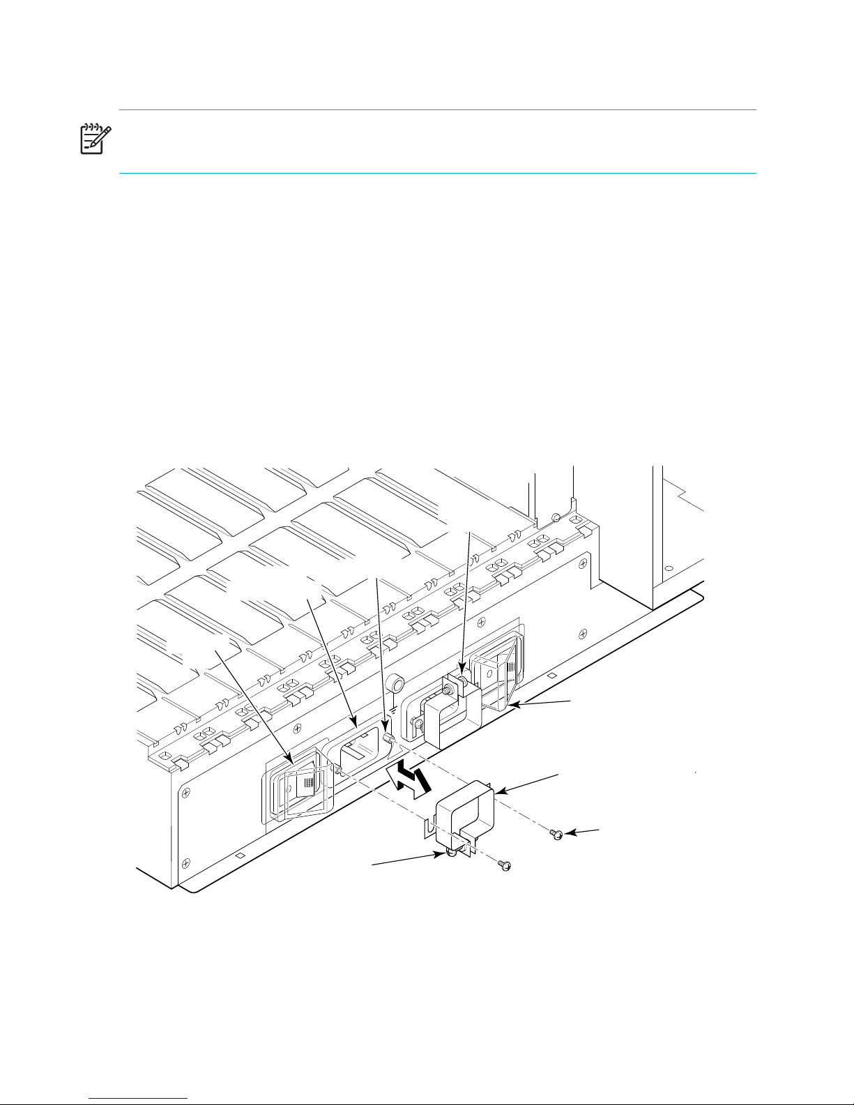
2. Verify that the AC switch covers are installed over the AC switches.
These clear plastic covers fit over the AC switches with their edges tucked underneath the
outlet covers, preventing the AC switches from being powered on or off accidentally (see
Figure 12).
3. Connect the AC power cord retainers to the chassis:
a. Orient a retainer against the AC panel as shown in Figure 12.
b. Place the retainer tabs under the two jack screws on either side of the power receptacle
and tighten the screws.
4. Repeat step 3 for the other retainer (note that the power cord retainers are oriented in the
same direction as the power receptacles).
Clamping
Screw
Jack
AC Power
Screw (2x)
Receptacle (2x)
AC Switch
(2x)
P
1&3
LY
RSUPP
E
W
O
P
200-240 VAC 12A 50-60 Hz
!
200-240 VA
Clamping
Screw
Figure 12 AC panel and power cord retainers
O
W
RSUPPL
E
C1
Y
2A
2&4
50-60 Hz
AC Switch Cover (2x)
Power Cord
Retainer (2x)
Retainer
Attaching
Screw (2x)
scale: 5/16" = 1"
POWER S
2.014
Installing and configuring the switch44
Page 45

5. Loosen the clamping screw on each retainer, insert the power cords through the retainers
into the power receptacles on the Core Switch 2/64 or the SAN Director 2/128, and
tighten the clamping screws.
The power cords are designed with left bends, so each should route to opposite sides of the
chassis.
6. Ensure that the power cord has a minimum service loop of 6 inches available at the
connection to the switch and is routed so that it is not exposed to stress.
7. Connect the power cords to a power source with voltage of 200 to 240 VAC, 50 to 60 Hz.
8. Position AC power switches to position 1.
The AC power switches light up green when switched on and power is supplied.
NOTE: The switch automatically performs a power-on self-test (POST) by default each time it is
powered on. POST takes approximately 10 minutes and is complete when indicator light
activity returns to its standard state. For information about LED patterns, see ”Interpreting LED
activity” on page 64).
CAUTION: To prevent a potential IP address conflict, do not connect the Core Switch 2/64 or
the SAN Director 2/128 to the network until the IP addresses are configured. See ”Core
Switch 2/64” on page 53 for additional information.
Establishing a serial connection
The initial communication to a Core Switch 2/64 or a SAN Director 2/128 switch requires a
serial connection. Follow these steps to establish a serial connection and log in to the switch:
1. Verify that the switch is powered on and that POST is complete by verifying that all power
LED indicators on the 16-port cards and CP cards are displaying a steady green light.
2. Use the serial cable provided with the switch to connect the console port on the active CP
card to a computer workstation.
The console port is the second serial port from the top of the CP card; the active CP card is
indicated by an illuminated (blue) LED (see ”CP cards” on page 68). The Active CP LED in
the standby CP card should be off (not illuminated).
45Core Switch 2/64 and SAN Director 2/128 installation guide
Page 46

NOTE: The console port is intended primarily for use during the initial setting of the IP
address and for service purposes. If necessary, the adapter on the serial cable can be removed
to allow for an RJ45 serial connection.
3. Access the switch using a terminal emulator application (such as HyperTerminal on
Windows 95, Windows 2000, or Windows NT, or TERM in a UNIX
®
environment).
NOTE: Both the Core Switch 2/64 and the SAN Director 2/128 support up to two telnet
sessions with administrative privileges at the same time.
4. Disable any serial communication programs running on the workstation (such as
synchronization programs).
5. Open the terminal emulator application and configure as follows:
•Bits per second: 9600
•Databits: 8
•Parity: None
•Stop bits: 1
• Flow control: None
6. When the terminal emulator application stops reporting information, press Enter.
7. Log in to the switch as admin. The default password is password.
NOTE: At the initial login, you are prompted to enter new admin and user passwords.
Installing and configuring the switch46
Page 47

8. Modify passwords, if desired. Passwords can be 8 to 40 characters long and should
include a combination of numbers and upper/lowercase letters
. To skip modifying the
password, press Ctrl-C.
Example:
Fabric OS (swDir)
swDir login: admin
Password:
Please change your passwords now.
Use Control-C to exit or press 'Enter' key to proceed.
Password was not changed. Will prompt again at next login
until password is changed.
swDir:admin>
9. Check the Active CP LED on the CP cards in slots 5 and 6 (see Figure 11), or enter the
haShow command to verify which CP card is active.
The configuration can be modified only through a login session to the active CP card.
Example:
swDir: admin> haShow
Local CP (Slot 6, CP1): Active
Remote CP (Slot 5, CP0): Standby
HA Enabled, Heartbeat Up, State Synchronized
Manage cables
The SAN Director 2/128 cables can be managed in a variety of ways, including the routing
them, as follows:
• Through the cable management tray
• Out either side of the chassis
• Through patch panels or cable channels on the sides of the rack
47Core Switch 2/64 and SAN Director 2/128 installation guide
Page 48

Two items are provided to assist with cable management:
• Cable management tray—The cable management tray is attached to the bottom of the
chassis (see Figure 12) and can be used to route the power cables and other cables down
below the chassis or out the sides of the chassis. Routing the cables down through the holes
in the management tray requires minimum of 3U (rack units) below the switch.
• Cable guides (pillars)—A set of 16 cable guides (pillars) are provided with the switch and
can be used to organize the port cables into logical groups, such as according to port
quads (sets of four neighboring ports). The cable guides do not attach to the chassis (see
Figure 13).
Cable
Management
Guide
scale: .50" = 1"
2.029
Figure 13 Cable guide (pillar)
The cable guides serve to keep the cables evenly spaced and to hold them away from the
port cards, making card replacement easier and preventing the cables from bending to less
than the minimum bend radius.
CAUTION: Do not route the cables in front of the air exhaust vent, which is located at the top
of the port side of the chassis. Arrange the cables so that the minimum bend radius is not
exceeded; for a 50-micron cable, the minimum bend radius is 2 inches under full tensile load
and 1.2 inches with no tensile load. Tie wraps are not recommended for optical cables
because they are easily overtightened and can break the optical cables.
To keep LEDs visible and make it easy to replace components, route cables down in front of the
cards, not across adjacent cards or in front of the power supplies. Figure 14 provides an
example in which cables for each card are routed in front of that card and are out of the way
of other components.
Installing and configuring the switch48
Page 49

Leave at least one meter of slack for each fiber optic cable. This provides room to remove and
replace the port card, allows for inadvertent movement of the rack, and helps prevent the
cables from being bent to less than the minimum bend radius.
Use the cable guides provided with the switch to group the cables. These guides help to keep
individual ports accessible by keeping the cables evenly spaced. If ISL Trunking is in use,
grouping the cables by trunking group is recommended. The ports are color-coded to indicate
which ports can be used in the same ISL Trunking group. Four ports marked with solid black
ovals alternate with four ports marked with oval outlines.
NOTE: ISL Trunking is a Fabric OS feature that enables distribution of traffic over the
combined bandwidth of up to four ISLs between two directly adjacent switches, while
preserving in-order delivery. For more information, refer to the HP StorageWorks features
overview for the Fabric OS version running on your switch.
Due to the wavelengths used in transmitting data, a minimum length is required for cables that
connect the Core Switch 2/64 or the SAN Director 2/128 ports to device ports, as follows:
• 9 microns, single-mode (SM)—2 meters
• 50 microns, multimode (M5)—2 meters
• 62.5 microns, multimode (M6)—2 meters
49Core Switch 2/64 and SAN Director 2/128 installation guide
Page 50

1 2 3 4 5 6 7 8 9 10
!
15
d
14
c
13
b
12
a
11
d
10
c
9
b
8
a
7
d
6
c
5
b
4
a
3
d
2
c
1
b
0
a
15
15
14
13
12
10
d
d
14
c
c
13
b
b
12
a
a
11
11
d
d
10
c
c
9
9
b
b
8
8
a
a
7
7
d
d
6
6
c
c
5
5
b
b
4
4
a
a
3
3
d
d
2
2
c
c
1
1
b
b
0
0
a
a
!
15
d
14
c
13
b
12
IOIOIRS - 232
a
11
d
10
c
9
b
8
Link
a
10/100Mb/s
7
Active CP
d
6
c
5
b
4
a
3
d
2
c
1
b
0
a
!
!
!
!
IOIOIRS - 232
Link
10/100Mb/s
Active CP
!
!
15
15
d
d
14
14
c
c
13
13
b
b
12
12
a
a
11
11
d
d
10
10
c
c
9
9
b
b
8
8
a
a
7
7
d
d
6
6
c
c
5
5
b
b
4
4
a
a
3
3
d
d
2
2
c
c
1
1
b
b
0
0
a
a
!
!
15
15
d
d
14
14
c
c
13
13
b
b
12
12
a
a
11
11
d
d
10
10
c
c
9
9
b
b
8
8
a
a
7
7
d
d
6
6
c
c
5
5
b
b
4
4
a
a
3
3
d
d
2
2
c
c
1
1
b
b
0
0
a
a
!
15
14
13
12
11
10
9
8
7
6
5
4
3
2
1
0
!
!
POWER SUPPLY 4
!
d
c
!
b
a
d
POWER SUPPLY 3
c
b
a
d
!
c
b
!
a
d
c
POWER SUPPLY 2
b
a
POWER SUPPLY 1&3 POWER SUPPLY 2&4
200-240 VAC 12A 50-60 Hz
200-240 VAC 12A 50-60 Hz
scale: 1/4" = 1"
Figure 14 Effective cable management (Director 2/128 shown)
Installing and configuring the switch50
!
!
POWER SUPPLY 1
2.033
Page 51

PID format summary
This section describes the process ID (PID) addressing format, which is one of several used in
Fibre Channel operations. The PID parameter is used by the routing and zoning services in
Fibre Channel fabrics to identify ports in the network.
The PID format is analogous to specifying the physical switch and port that a device is attached
to in data networks. It is not analogous to an IP address. PIDs are assigned by a Fibre Channel
switch when a device logs into the fabric.
A sample PID looks like this: 011F00
Many scenarios cause a device to receive a new PID. For example, a device can receive a new
PID when the device is unplugged from one port and plugged into a different port. (This might
occur when cabling around a bad port or when moving equipment around.) It may also occur
when you change the Domain ID of a switch, which may be necessary when merging fabrics,
or changing compatibility mode settings.
NOTE: All switches running Fabric OS version 4.0.x or later are shipped with the PID Format
enabled, so it is not necessary to change the PID format on these switches. For example, the
SAN Switch 2/32 and Core Switch 2/64 always use Core Switch PID format 1. This
parameter is always 1 and cannot be changed.
Mixed fabric environment with different switch platforms
Fabric OS v2.6.2, v3.1.2, and v4.2.x introduced a new switch PID format: Extended Edge PID
(format 2). Extended Edge PID is useful if you introduce a Fabric OS 4.2.x switch into a fabric
that consists solely of Fabric OS v2.x and v3.x switches. Before adding a Fabric OS 4.2.x
switch to such a fabric, refer to the HP StorageWorks Procedures user guide for the Fabric OS
version running on your switch to get information on the Extended Edge PID format.
NOTE: Switches must operate with Fabric OS v2.6.2, v3.1.2, v4.2.x, and later to use the
Extended Edge PID format.
If Extended Edge PID is set (before a downgrade from the current Fabric OS release to an
earlier Fabric OS release that does not support the Extended PID format), PID needs to be set
back to a supported format, such as Core PID (format 1) or native PID (format 0).
51Core Switch 2/64 and SAN Director 2/128 installation guide
Page 52

Configuration overview
The Core Switch 2/64 includes two logical switches in one cabinet. Each switch can have up
to 64 ports. The SAN Director 2/128 is a single switch in one cabinet. It can have up to128
ports. This section provides information about how each switch is configured.
Core Switch 2/64
The Core Switch 2/64 can contain up to two logical switches, each with its own configuration:
one logical switch for any 16-port cards in slots 1–4, and one logical switch for any 16-port
cards in slots 7–10.
The configuration information for both logical switches is stored in the WWN card and in the
CP cards’ flash memory. The configuration settings are automatically mirrored to the standby
CP card. In this way, the most current configuration is available even if the active CP card fails.
You can also back up the configuration by uploading the settings to a workstation using the
configUpload command (see ”Backing up system configuration settings” on page 131),
and you can download the settings to the active CP card using the configDownload
command (see ”Restoring the system configuration settings” on page 132).
NOTE: HP recommends a routine backup of the configuration to ensure that the current
configuration is available if it is needed.
The Core Switch 2/64 configuration can be modified only through a login session to the active
CP card. The switch supports up to two simultaneous telnet sessions (with administrative
privileges).
NOTE: For fabric OS v4.1 or later, different logins are provided for each logical switch.
Logical Switch 0 has logins User0, Admin0, Factory0, and Root0. Logical Switch 1 has
logins User1, Admin1, Factory1, and Root1. For versions earlier than v4.1, the same
administrative login account applies to both logical switches. If the password is changed on
switch 0, it is automatically changed on switch 1.
Installing and configuring the switch52
Page 53

SAN Director 2/128
Configuration information for the SAN Director 2/128 is stored in the WWN card and in the
CP cards’ flash memory. The configuration settings are automatically mirrored to the standby
CP card. In this way, the most current configuration is available even if the active CP card fails.
You can also back up the configuration by uploading the settings to a workstation using the
configUpload command (see ”Backing up system configuration settings” on page 131),
and you can download the settings to the active CP card using the configDownload
command (see ”Restoring the system configuration settings” on page 132).
NOTE: HP recommends a routine backup of the configuration to ensure that the current
configuration is available if it is needed.
You can modify the Core Switch 2/128 configuration only through a login session to the active
CP card. The switch supports up to two simultaneous telnet sessions (with administrative
privileges).
Initial configuration parameters
This section describes the initial configuration settings for the Core Switch 2/64 and SAN
Director 2/128.
Core Switch 2/64
CAUTION: Resetting a logical IP address while the switch is running in the fabric may cause
Advanced Web Tools, Fabric Watch, SNMP, and other applications to terminate.
The Core Switch 2/64 ships with the following factory-installed settings:
• General system parameters (modifiable through the configure command).
• WWNs for both logical switches: The two WWNs are not modifiable; both are
preconfigured and are usually based on the chassis serial number.
• Domain ID: One Domain ID for any 16-port cards in slots 1-4, and one for any 16-port
cards in slots 7-10. Domain IDs can be modified through the configure command. The
default Domain ID for both logical switches is 1.
• A native IP address, host name, subnet mask, and gateway address for both CP card slots
(modifiable through the ipAddrSet command).
53Core Switch 2/64 and SAN Director 2/128 installation guide
Page 54

• Logical IP addresses: A logical IP address and subnet mask for both logical switches
(modifiable through the ipAddrSet command).
• Switch names for both logical switches (modifiable through the switchName command).
• Switch status policies (modifiable through the switchStatusPloicySet command).
• Core PID setting (modifiable through the configure command).
Table 5 lists Core Switch 2/64 default configuration settings.
Table 5 Core Switch 2/64 default parameters
Parameter Default
Switch Name for Logical Switch 0 sw0
Base IP Address for Logical Switch 0 10.77.77.77
Logical Switch 0 and 1 Subnet Mask 255.255.255.0
CP card 0 and 1 Subnet Mask 255.255.255.0
Ethernet Link Mode Auto
CLI Timeout 15 Minutes
SAN Director 2/128
The SAN Director 2/128 ships with the following factory-installed settings:
• IP addresses (or native IP address), host names, subnet masks, and gateway addresses for
both CP cards
• IP address and subnet mask for the SAN Director 2/128
• Director name
• Switch status policies
• Domain ID for the SAN Director 2/128 (optional)
• WWN for the SAN Director 2/128
NOTE: The SAN Director 2/128 WWN is initially set by the factory to match the license ID
(which is based on the chassis serial number). The WWN can be changed, but the license ID
cannot be modified.
Installing and configuring the switch54
Page 55

Table 6 lists Director 2/128 default configuration settings.
Table 6 Director 2/128 default parameters
Parameter Default
Switch Name swDIR
Base IP Address for CP 0 10.77.77.75
Subnet Mask 255.255.255.0
CP card 0 and 1 Subnet Mask 255.255.255.0
Ethernet Link Mode Auto
CLI Timeout 15 Minutes
Setting up a configuration
The following are the basic steps required for setting up an initial configuration for the SAN
Director 2/128 or modifying the initial configuration for the Core Switch 2/64:
1. Log in to the switch (see ”Establishing a serial connection” on page 45).
2. Set up IP addresses (see ”Configure IP addresses for CP cards” on page 56 and ”Configure
IP address for the switch” on page 57).
3. Establish an Ethernet connection (optional). See ”Establish an Ethernet connection” on
page 58.
4. Specify the switch name (see ”Customize a switch name” on page 59).
5. Set up the switch status policies (see ”Specify status policies” on page 59).
6. Specify the Domain ID for the switch (see ”Set the Domain ID” on page 60).
7. Connect to the fabric and establish fabric parameters, including PID settings (see ”Connect
to the fabric and configure fabric parameters” on page 60).
8. Enable software licenses, as necessary (see ”Enable software licenses” on page 61).
9. Back up the configuration (see ”Back up the configuration” on page 62).
For additional information about these commands, refer to the HP StorageWorks command
reference guide for the Fabric OS version running on your switch.
55Core Switch 2/64 and SAN Director 2/128 installation guide
Page 56

Configure IP addresses for CP cards
The Core Switch 2/64 and the SAN Director 2/128 Director each require three IP addresses,
which are configured using the ipAddrSet command. IP addresses are required for both CP
cards (CP0 and CP1) and for the switch.
NOTE: Use a block of three IP addresses that are consecutively numbered in the last octet. The
IP and gateway addresses must reside on the same subnet.
Resetting an IP address while the switch is online breaks any connections to that IP address
and forces a restart of any HTTP, SNMP, and API daemons.
The addresses 10.0.0.0–10.0.0.255 are reserved and used internally by the switch.
The default IP addresses and host names for the Core Switch 2/64 and the SAN Director
2/128 CPs are as follows:
• 10.77.77.75 CP0 (the CP card in slot 5 at the time of configuration)
• 10.77.77.74 CP1 (the CP card in slot 6 at the time of configuration
Configuration changes can only be made via the active CP card. If the CP card in slot 5 is not
the active CP card, disconnect the serial cable and connect it to the CP card in slot 6; then log
in as admin.
Follow these steps to configure the IP addresses for both CP cards (from the active CP card):
1. Enter the ipAddrSet command at the prompt: include option 2 for the CP card in slot 5 or
3 for the CP card in slot 6.
Example:
swDir:admin> ipAddrSet -cp 2
2. Enter the requested information at the prompts.
The default information for the CP card in slot 5 is displayed.
Example:
Ethernet IP Address [10.77.77.75]:
Ethernet Subnetmask [255.0.0.0]:
Host Name [CP0]:
Gateway Address [0.0.0.0]:
Installing and configuring the switch56
Page 57

NOTE: The host name is the name assigned to the CP card. The same gateway address must
be used for both CP cards (these gateway addresses are referenced for the IP addresses).
3. Press Enter to update the IP address of the active CP card immediately.
4. Repeat these steps to configure the IP address of the standby CP card.
The IP address of the standby CP card is updated at the next reboot.
Configure IP address for the switch
The Core Switch 2/64 and SAN Director 2/128 each has its own IP address and
corresponding subnet mask. The default IP address is 10.77.77.77 (base IP address for logical
switch 0 in Core Switch 2/64).
CAUTION: Resetting an IP address while the switch has active IP traffic from such applications
as Fabric Manager, Fabric Watch, and SNMP can cause traffic to be interrupted or stopped.
Changing the IP address causes a domain address format RSCN to be issued.
Follow these steps to configure the IP address for the Core Switch 2/64 or the SAN Director
2/128 (from the active CP card):
CAUTION: Configuration changes can be made only via the active CP card. If the CP card in
slot 5 is not the active CP card, disconnect the serial cable and connect it to the CP card in slot
6, and then log in as admin.
1. Enter ipAddrSet at the prompt.
2. Enter the requested information for this IP address at the prompts.
Example:
Ethernet IP Address [10.77.77.77]:
Ethernet Subnetmask [0.0.0.0]:
Fibre Channel IP Address [none]:
Fibre Channel Subnet Mask [none]:
The IP address is updated immediately.
57Core Switch 2/64 and SAN Director 2/128 installation guide
Page 58

3. Reboot the CP card by entering the reboot command at the prompt.
CAUTION: The terminal serial port can be used to monitor error messages through a serial
connection. HP does not recommend using the terminal serial port as a command interface
during normal operations. If this port is not going to be in ongoing use, remove the serial cable
and protect the port from dust by replacing the shipping cap.
Establish an Ethernet connection
After using a serial connection to configure the IP addresses for the Core Switch 2/64 or the
SAN Director 2/128 (see ”Configure IP addresses for CP cards” on page 56 and ”Configure
IP address for the switch” on page 57), you can connect the active CP card to the local area
network (LAN) if desired.
NOTE: HP recommends connecting the CP cards to a private network/VLAN.
By establishing an Ethernet connection, you can complete the switch configuration using either
the serial session or a telnet session. However, you must ensure that the Core Switch 2/64 or
the SAN Director 2/128 are not modified from other connections at the same time.
To establish an Ethernet connection to the switch, follow these steps:
1. Remove the shipping plug from the Ethernet port on the active CP card.
2. Insert one end of an Ethernet cable into the Ethernet port.
3. Connect the other end to an Ethernet 10/100 Base-T LAN.
The Core Switch 2/64 or the SAN Director 2/128 can now be accessed by remote
connection using any of the available management tools, such as telnet or the optional
Fabric Manager application.
4. To complete any additional switch configuration procedures through a telnet session, log in
to the switch by telnet, using the admin login. The default password is password.
Installing and configuring the switch58
Page 59

Customize a switch name
The switch name of the Core Switch 2/64 or the SAN Director 2/128 Director can be up to
15 characters long; can include alpha, numeric, and underscore characters; and must begin
with an alpha character. The default name for the Core Switch 2/64 or the SAN Director
2/128 is swDir. HP recommends using swDir in the name to allow easy identification.
To customize the name, follow these steps:
1. Enter the switchName command with the new name in quotes.
Example:
swDir:admin> switchName "sw10"
For details about the switchName command, refer to the HP StorageWorks command
reference guide for the Fabric OS version running on your switch.
2. Record the new name for future reference.
NOTE: Changing the name causes a domain address format RSCN to be issued.
Specify status policies
To specify custom status policies, follow these steps:
1. Enter the switchStatusPolicySet command at the prompt.
For more information about the switchStatusPolicySet command, refer to the HP
StorageWorks command reference guide for the Fabric OS version running on your switch.
2. Complete the prompts to specify the desired policies.
NOTE: To completely deactivate an alarm for a particular condition, enter 0 at the
corresponding prompt.
59Core Switch 2/64 and SAN Director 2/128 installation guide
Page 60

Set the Domain ID
Each switch in the fabric must have a unique Domain ID. You can set the Domain ID using the
configure command. You can also allow the system to set the Domain ID automatically.
NOTE: The default Domain ID for the Core Switch 2/64 or the SAN Director 2/128 is 1.
To set the Domain ID, follow these steps:
1. Enter the fabricShow command to determine the available Domain IDs.
2. Enter the switchDisable command to disable the Core Switch 2/64 or the SAN
Director 2/128.
3. Enter the configure command.
4. Enter y at the fabric parameters prompt:
Fabric parameters (yes, y, no, n): [no] y
5. Enter a unique Domain ID:
Domain: (1..239) [1] 3
6. Complete the remaining prompts or press Ctrl+D to accept the other settings and exit.
7. Enter the switchEnable command to reenable the Core Switch 2/64 or the SAN
Director 2/128.
Connect to the fabric and configure fabric parameters
Before connecting the Core Switch 2/64 or the SAN Director 2/128 to the fabric, verify that
all the switches in the fabric use the correct port identifier (PID) settings. For information on
setting the PIDs, refer to the HP StorageWorks procedures user guide for the Fabric OS version
running on your switch.
To connect the switch to the fabric, follow these steps:
1. Add SFP transceivers and cables to the Fibre Channel ports, as required.
The ports are color-coded to indicate which ones can be used in the same trunking groups.
Four ports marked with solid black ovals alternate with four ports marked with oval outlines.
The ports and cables used in trunking groups must meet specific requirements. For a list of
these requirements, refer to the “ISL Trunking” section of the HP StorageWorks features
overview for the Fabric OS version running on your switch.
Installing and configuring the switch60
Page 61

2. Position one of the SFP transceivers so that the key is oriented correctly to the port. Insert the
transceiver into the port until it is firmly seated and the latching mechanism clicks.
Transceivers are keyed so that they can be inserted only with the correct orientation. If a
transceiver does not slide in easily, ensure that it is correctly oriented. For instructions that
are specific to the transceiver model, refer to the transceiver manufacturer’s documentation.
3. Position a cable so that the key (the ridge on one side of the cable connector) is aligned
with the slot in the transceiver; then, insert the key into the transceiver until the latching
mechanism clicks.
Cables are keyed so that they can be inserted only with the correct orientation. If a cable
does not slide in easily, ensure that it is correctly oriented.
4. Repeat step 1 through step 3 for the remaining ports.
5. Organize the cables as required. For recommendations regarding cable management,
refer to ”Manage cables” on page 47.
6. Check the Core Switch 2/64 or the SAN Director 2/128 for switch and port status by
entering the switchShow command at the prompt.
The switchShow command provides detailed information about the switch. For more
information about this command, refer to the HP StorageWorks command reference guide
for the Fabric OS version running on your switch.
7. Check the fabric for ISLs, switch names, or other status by entering the fabricShow
command at the prompt.
The fabricShow command provides general information about the fabric. For details
about this command, refer to the HP StorageWorks command reference guide for the
Fabric OS version running on your switch.
8. To establish additional system parameters, use the configure command. For details
about this command, refer to the HP StorageWorks command reference guide for the
Fabric OS version running on your switch.
Enable software licenses
See ”Verifying optional software licenses” on page 133 for information about determining
currently enabled licenses and activating or obtaining additional licenses.
61Core Switch 2/64 and SAN Director 2/128 installation guide
Page 62

Back up the configuration
HP recommends that you save all key configuration data for the Core Switch 2/64 or the SAN
Director 2/128—including license key information—and upload it to a host for emergency
reference. Routine backups of the configuration are recommended to ensure the current
configuration is available if needed.
Be sure to backup after all zoning configurations and other changes are complete.
See ”Backing up system configuration settings” on page 131 for back up procedures.
Installing and configuring the switch62
Page 63

3Operating the switch
The Core Switch 2/64 and SAN Director 2/128 are engineered for reliability and do not
require routine operational steps or maintenance. This chapter covers the following topics,
which describe methods you can use to determine if any non-routine operational steps or
maintenance are required:
• Interpreting LED activity, page 64
• Diagnostics and troubleshooting overview, page 78
• Obtaining chassis and component status, page 79
• Interpreting POST and boot results, page 80
• Diagnostics, page 81
The following subsections provide specific component LED and CLI information for both
switches:
• 16-port cards, page 64
• CP cards, page 68
• Power supplies, page 71
• Blower assemblies, page 74
• WWN card, page 75
You can also set up monitoring alerts using SNMP, syslog, Advanced Web Tools, or optional
software features [for example, Fabric Watch and Advanced Performance Monitoring (APM)].
NOTE: For additional information, refer to the HP StorageWorks Fabric Watch user guide, the
HP StorageWorks Advanced Web Tools user guide, and the HP StorageWorks features
overview
for the Fabric OS version running on your switch.
63Core Switch 2/64 and SAN Director 2/128 installation guide
Page 64

Interpreting LED activity
System activity and status can be determined through the activity of the LED indicators on the
switch. There are three possible LED states:
• No light
• Steady light, in one of the following colors:
•Green
• Orange (also referred to as amber in related documentation)
• Yellow (appears when both green and orange LED elements are lit)
• Flashing light (green, orange, or yellow)
The LEDs may flash green, yellow, or orange while the switch is booting or while POST or other
diagnostic tests are running. This is normal, and does not indicate a problem unless the LEDs
do not indicate that all components are operational after boot process, POST, and any
diagnostic tests are complete.
16-port cards
To determine the status of a 16-port card:
1. Check the LED indicators on the port card (see Figure 15).
The LED patterns may temporarily change during POST and other diagnostic tests. For
information about how to interpret the LED patterns, refer to Table 7.
2. Check the 16-port card status using the slotShow command (see ”Obtaining chassis and
component status” on page 79 for an example).
Operating the switch64
Page 65

Port Card
ON/OFF Switch
(in "OFF" position)
Power LED
Status LED
Port Speed LED
(16x)
Port Status LED
(16x)
scale: 5/16" = 1"
ON/OFF Switch
in "ON" position
!
15
d
14
c
13
b
12
a
11
d
10
c
9
b
8
a
7
d
6
c
5
b
4
a
3
d
2
c
1
b
0
a
!
Fibre Channel
Port (16x)
Ejector
(2x)
Figure 15 Front of 16-port card
2.017
65Core Switch 2/64 and SAN Director 2/128 installation guide
Page 66

Table 7 16-port card LED patterns
LED location/
Color Status Recommended action
purpose
Power Steady green Port card is receiving
power.
No light (LED is off) Port card is not receiving
power.
Status No light (LED is off) Port card is either
healthy or does not have
power.
Steady yellow Port card is faulty. Ensure card is firmly seated and
Slow-flashing yellow (on
2 seconds; then off 2
seconds)
Fast-flashing yellow (on
1/2 second; then off
1/2 second)
Port card is not seated
correctly or is faulty.
Environmental range
was exceeded.
No action required.
Ensure card is firmly seated and
has power.
Verify that the power LED is on.
check status with slotShow
command. If LED remains
yellow, consult switch supplier.
Pull card out and reseat it. If LED
continues to flash, replace card.
Check for out-of-bounds
environmental condition and
correct it.
Port Speed
(upper LED
adjacent to each
port)
No light (LED is off) Port is either set to
1 Gb/s mode, or it does
not have incoming
power.
Steady green Port is set to
2 Gb/s mode.
Verify that the power LED is on.
Use portCfgSpeed command
to change mode.
No action required.
Operating the switch66
Page 67

Table 7 16-port card LED patterns (continued)
LED location/
purpose
Port Status (lower
LED adjacent to
each port)
Color Status Recommended action
No light (LED is off) Port is not receiving
power, or there is no
light or signal carrier
detected.
Polling is in progress. Allow 60 seconds for polling to
Connected device is
configured in an offline
state.
Steady green Port is online (connected
to an external device)
but receiving no traffic.
Slow-flashing green (on
1 second; then off 1
second)
Port is online but
segmented, indicating a
loopback plug or cable
or an incompatible
switch.
Verify that the power LED is on,
and check the transceiver and
cable.
complete.
Verify the status of the
connected device.
No action required.
Verify that the correct device is
attached to the switch.
Fast-flashing green (on
1/4 second; then off
1/4 second
Flickering green Port is online, with traffic
Steady orange Port is receiving light or
Slow-flashing orange (on
2 seconds; then off 2
seconds)
Fast-flashing orange (on
1/2 second; then off
1/2 second)
Alternating
green/orange
Port is in internal
loopback (diagnostic).
flowing through port.
signal carrier, but it is
not online yet.
Port is disabled due to
diagnostic tests or
portDisable
command.
Transceiver or port is
faulty.
Port is bypassed. Reset port from workstation.
No action required.
No action required.
No action required.
Reset port from workstation.
Change transceiver or reset
switch from workstation.
67Core Switch 2/64 and SAN Director 2/128 installation guide
Page 68

CP cards
To determine the status of a CP card:
1. Check the LED indicators on the port card (see Figure 16).
The LED patterns may temporarily change during POST and other diagnostic tests; for
information about how to interpret the LED patterns, refer to Table 8.
2. Check port card status using the slotShow command (see ”Obtaining chassis and
component status” on page 79 for an example) and haShow command.
For additional information about these commands, refer to the HP StorageWorks command
reference guide for the Fabric OS version running on your switch.
Operating the switch68
Page 69

8
ON/OFF Switch
(in "ON" position)
Power LED
Status LED
ON/OFF Switch
in "OFF" position
!
RS-232
Modem Port
Link Status LED
Link Speed LED
10/100 Mb/s
Active CP LED
scale: 5/16" = 1"
Ejector
(2x)
IOIOIRS - 232
Link
10/100Mb/s
Active CP
!
Console Port
(10101)
Ethernet Port
CP Card
Captive Screw
(2x)
2.01
Figure 16 Front of CP card
69Core Switch 2/64 and SAN Director 2/128 installation guide
Page 70

Table 8 CP card LED patterns
LED location/
Color Status Recommended action
purpose
Power Steady green CP card is not
receiving power.
No light (LED is off) CP card is not
receiving power.
Status No light (LED is off) CP card is either
healthy or does not
have power.
Steady yellow CP card is faulty or
the switch is still
booting.
Slow-flashing yellow
(on 2 seconds; then
CP card is not seated
correctly or is faulty.
off 2 seconds)
No action required.
Ensure card is firmly seated
and has power.
Verify that the power LED is
on.
Ensure card is firmly seated
and switch has completed
booting. If LED remains
yellow, consult switch
supplier.
Pull card out and reseat it. If
LED continues to flash,
replace card.
Ethernet Link
Status (upper
LED beneath
Ethernet port)
Fast-flashing yellow
(on 1/2 second; then
Environmental range
exceeded.
off 1/2 second)
No light (LED is off) Either an Ethernet link
is not detected, or it
does not have
incoming power.
Flickering
green/yellow
Ethernet link is healthy
and traffic is flowing
through port.
Check for out-of-bounds
environmental condition and
correct it.
Ensure the card has power,
Ethernet cable is firmly
seated, and connected
device is functioning.
No action required.
Operating the switch70
Page 71

Table 8 CP card LED patterns (continued)
LED location/
purpose
Ethernet Link
Speed (lower
LED beneath
Ethernet port)
Active CP
(beneath
Ethernet Link
Status and
Speed LEDs)
Color Status Recommended action
No light (LED is off) Ethernet link speed is
10 Mb/s or CP card
does not have
incoming power.
Steady green Ethernet link speed is
100 Mb/s.
Steady blue Active CP card. No action required.
No light (LED is off) Standby CP card. No action required.
Ensure CP has power.
NOTE: To force a persistent
Ethernet link speed, use the
ifModeSet command.
No action required.
Power supplies
To determine the status of a power supply:
1. Check the LED indicators on the power supply (see Figure 17).
The LED patterns may temporarily change during POST and other diagnostic tests; for
information about how to interpret the LED patterns, refer to Table 9.
2. Check power supply status using the psShow command (see ”Obtaining chassis and
component status” on page 79 for an example).
The power supply status displays OK, Absent, or Faulty. If a power supply is absent or
faulty, contact the switch supplier to order replacement parts, as necessary.
71Core Switch 2/64 and SAN Director 2/128 installation guide
Page 72

scale: 3/16" = 1"
Power Supply
!
!
Locking Tab
Handle
Power LED
Predictive
Failure LED
Fail LED
Front of Power Supply
Figure 17 Power supply LEDs
scale: 3/8" = 1"
!
!
2.019
Operating the switch72
Page 73

Table 9 Power supply LED patterns
LED location/
Color Status Recommended action
purpose
Power No light
(LED is off)
Steady green Power supply is
Predictive
Failure
No light
(LED is off)
Flashing orange Power supply is about
Power supply is not
receiving power and
is not providing power
to the switch.
receiving power and
is providing power to
the switch.
Power supply is either
healthy or is not
receiving power.
to fail due to a failing
fan inside the power
supply.
Ensure power supply is firmly
seated, switch is receiving
power, both power cables
are connected, and AC
power switches are on.
No action required.
Check the power LED.
Replace power supply.
Failure No light
(LED is off)
Steady orange Either the switch has
Flashing orange Power supply is
Power supply is either
healthy or is not
receiving power.
power but this power
supply does not (AC
switch may be off) or
the power supply has
failed.
unable to supply
power.
Check the power LED.
Verify that the correct AC
power switch is on and
power supply is seated. If
orange light continues,
replace power supply.
Verify that the incoming
power meets power
requirements (refer to
”Technical specifications” on
page 135).
73Core Switch 2/64 and SAN Director 2/128 installation guide
Page 74

Blower assemblies
To determine the status of a blower assembly:
1. Check the LED indicators on the blower assembly (see Figure 18).
The LED patterns may temporarily change during POST and other diagnostic tests; for
information about how to interpret the LED patterns, refer to Table 10.
2. Check the blower assembly status using the fanShow command.
The status for each blower assembly displays OK, Absent, or Faulty. The RPM of each fan in
the assembly is also provided. If a blower assembly is absent or faulty, contact the switch
supplier to order replacement parts, as necessary.
scale:
1/8" = 1"
Power LED
Figure 18 Blower assembly LEDs
scale:
1/4" = 1"
Blower Assembly
Fault LED
Handle
Captive Screw
(2x)
2.020
Operating the switch74
Page 75

Table 10 Blower assembly LED patterns
LED location/
Color Status Recommended action
purpose
Power No light
(LED is off)
Steady green Blower assembly has
Fault No light
(LED is off)
Steady orange Blower assembly has a
Slow-flashing orange
(on 2 seconds; then off 2
seconds)
Fast-flashing orange
(on 1/2 second; then off
1/2 second)
Blower assembly does
not have incoming
power.
incoming power.
Blower assembly is either
healthy or does not have
incoming power.
failure (full or partial).
Blower assembly is not
seated correctly or is
faulty.
Environmental range
was exceeded.
Ensure that the blower assembly
is firmly seated and has power.
No action required.
Ensure that the blower assembly
has incoming power.
Replace blower assembly.
Pull unit out and reseat. If LED
continues to flash, replace unit.
Check for out-of-bounds
environmental condition, resolve
any problems, and reseat unit. If
LED continues to flash, replace
unit.
WWN card
To determine the status of the WWN card:
1. Check the LED indicators on the WWN bezel (see Figure 19) and verify that they reflect the
actual status of the components.
The WWN bezel covers the WWN card and allows its LEDs to shine through. The LEDs on
the WWN bezel provide a consolidated view of the port card status, CP card status, and
power supply status. The LED patterns may temporarily change during POST and other
diagnostic tests; for information about how to interpret the LED patterns, refer to Table 11.
2. Check the WWN card status using the commands listed in Table 11.
Difficulty retrieving or modifying this data could indicate a WWN card failure:
75Core Switch 2/64 and SAN Director 2/128 installation guide
Page 76
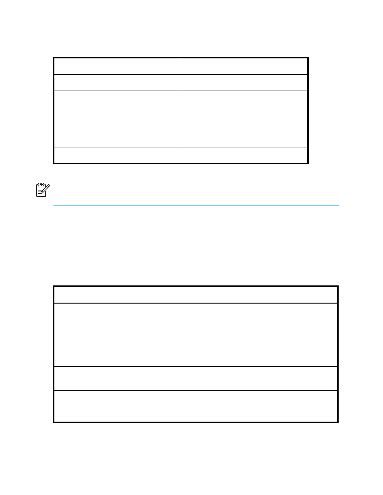
Table 11 Data stored on the WWN card
Data Related commands
WWN values wwn, chassisShow
Data about the chassis and WWN card chassisShow
Ethernet and Fibre Channel IP address
information for the CP cards
History log information historyShow, historyLastShow
Names of switch switchName
ipAddrShow, ipAddrSet
NOTE: For additional information about these commands, refer to the HP StorageWorks
command reference guide for the Fabric OS version running on your switch.
3. If the error log or serial console display error messages that indicate problems with WWN
units (see Table 12), the WWN card might have failed.
WWN units correspond to information specific to the WWN card and are displayed by
the chassisShow command. For additional information about this command, refer to the
HP StorageWorks command reference guide for the Fabric OS version running on
your switch.
Table 12 Messages that can indicate WWN card failure
Type of message Sample error message
WWN unit fails its FRU (field
replaceable unit) header access.
WWN unit is being faulted. 0x24c (fabos): Switch: switchname,
WWN unit is not present or is not
accessible.
Writing to the FRU history log
(hilSetFruHistory) has failed.
Operating the switch76
0x24c (fabos): Switch: switchname, error
EM-I2C_TIMEOUT, 2, WWN 1 I2C timed out:
state 0x4
Critical EM-WWN_UNKNOWN, 1, Unknown WWN #2
is being faulted
0x24c (fabos): Switch: switchname, Error
EM-WWN_ABSENT, 2, WWN #1 not present
0x24c (fabos): Switch: switchname, Error
EM-HIL_FAIL, 2, HIL Error:
hilSetFruHistory failed, rc=-3 for SLOT 3
Page 77

NOTE: For more information about error messages, refer to the HP StorageWorks system error
messages reference guide for the Fabric OS version running on your switch.
Port Cards
(Slots 1-4 and 7-10)
Power LED
(upper LED)
Status LED
(lower LED)
Figure 19 WWN bezel LEDs
CP Cards
(Slots 5 and 6)
Power LED
(upper LED)
Status LED
(lower LED)
Badge Captive
scale:
5/16" = 1"
10
987654321
pwr4
pwr3
pwr2
pwr1
Screw (2x)
Power Supplies
Power LED/
Status LED
2.021
Table 13 WWN bezel LED patterns
LED location/purpose Color Status Recommended action
16-port card/CP card
power
16-port card/CP card
status
Note: If a card slot or power supply bay has a filler panel installed, the corresponding LEDs on the WWN card
do not light up.
Power supply
power/status
Steady green Power is OK. No action required.
Steady amber Card is faulty. Check card.
No light (LED is OFF) Card is OK. No action required.
Steady green Power is OK. No action required.
Steady amber Power supply is faulty. Check power supply.
77Core Switch 2/64 and SAN Director 2/128 installation guide
Page 78

NOTE: If a Status LED on the WWN bezel flashes, the Power LED on the WWN bezel also
flashes, for increased visibility.
Diagnostics and troubleshooting overview
For information about troubleshooting the entire fabric, refer to the HP StorageWorks
procedures user guide for the Fabric OS version running on your switch.
The Core Switch 2/64 and the SAN Director 2/128 include a number of diagnostic aids to
assist with troubleshooting, including LEDs on the hardware, commands that display current
status, diagnostic tests for hardware and software, and error messages. In addition, a number
of optional management tools are available, such as Fabric Manager, Fabric Watch, and
Advanced Performance Monitoring.
If the switch does not operate as expected, use the following steps to diagnose the problem:
• Check the LEDs and refer to the LED tables (see ”Interpreting LED activity” on page 64) for
recommended actions.
• Review the results of the last POST run by the switch (see ”Interpreting POST and boot
results” on page 80).
• Review the error logs (for more information, refer to the HP StorageWorks system error
messages reference guide for the Fabric OS version running on your switch).
• Enter the sensorShow command to determine the status of the hardware components.
• Run diagnostic tests (see ”Diagnostics” on page 81).
• Reboot the switch or power the entire chassis off/on.
If the problem is still unresolved after these steps, contact your support provider. The
information required by your support provider is listed under ”Rack stability” on page 11.
Operating the switch78
Page 79

Obtaining chassis and component status
The CLI commands listed in Table 14 provide status and environmental information about the
chassis and its components. These commands provide information only, and they do not
interrupt traffic flow. For more information about these commands, refer to the HP
StorageWorks command reference guide for the Fabric OS version running on your switch.
NOTE: The environmental commands report internal temperatures within the chassis. The
16-port cards can withstand internal temperatures of up to 75
continue to operate up to 80
o
40
C or less.
o
C. However, the ambient temperature outside the chassis must be
o
C and the CP cards can
Table 14 Environmental status and maintenance commands
Command Information displayed
sensorShow Temperature readings for the port cards
Temperature readings for the CP cards
Status and RPM of all operational fans
Status of all operational power supplies
tempShow Temperature readings for the port cards
Temperature readings for the CP cards
psShow Status of all operational power supplies
fanShow Status and RPM of all operational fans
chassisShow Serial number, time awake, and additional information about each component
slotShow Slot occupancy
errShow Switch error log (lists status of any marginal/failed components)
NOTE: Enter CLI commands with all lowercase characters.
79Core Switch 2/64 and SAN Director 2/128 installation guide
Page 80

Interpreting POST and boot results
The Core Switch 2/64 and the SAN Director 2/128 perform power on self test (POST) by
default each time the chassis is powered on or the switch is rebooted or reset. You can reboot
the switch using the switchReboot, reboot, or fastBoot commands. The fastBoot
command reboots the switches without running POST. If the active CP card is rebooted, it fails
over to the standby CP card.
POST
Each time the switch is powered on or reset, the switch automatically performs POST, a system
check during which LED patterns might vary.
To verify that POST has completed without error:
• Verify that all LEDs return to a normal state after POST completes (see ”Interpreting LED
activity” on page 64).
If one or more LEDs do not return to a normal state, and this is not due to the switch being
set to beacon, refer to the relevant LED table to identify and correct the problem. For port
cards and CP cards, the slotShow command can be used to check the status of the slots.
For information about turning beaconing on/off, refer to the HP StorageWorks procedures
user guide for the Fabric OS version running on your switch.
• Verify that the switch prompt appears when POST completes.
If it does not appear, POST was not successfully completed. Contact the switch supplier for
support.
• Review the system log.
Any errors detected during POST are written to the system log, which is accessible through
the errShow command. For information about error messages, refer to the HP
StorageWorks system error messages reference guide for the Fabric OS version running on
your switch.
POST includes the following steps:
• Preliminary POST diagnostics are run.
• Operating system is initialized.
• Hardware is initialized.
• Diagnostic tests are run on several functions, including circuitry, port functionality, ability to
send and receive frames, all aspects of memory, parity, statistics counters, and serialization.
Operating the switch80
Page 81

Boot
Boot completes in a minimum of three minutes if POST is run. In addition to POST, boot
includes the following steps after POST is complete:
• Universal port configuration is performed.
• Links are initialized.
• Fabric is analyzed. If any ports are connected to other switches, the switch participates in a
fabric configuration.
• The switch obtains a Domain ID and assigns port addresses.
• Unicast routing tables are constructed.
• Normal port operation is enabled.
Diagnostics
Diagnostic tests are automatically run during POST to check the status of the switch. Any error
messages generated during POST are sent to the error logs and to the serial console, if
connected.
Diagnostic tests can also be run manually to test and troubleshoot the hardware and the
firmware, including internal connections and circuitry, transceivers, and port cables. However,
diagnostic tests are generally intended for use by support personnel.
NOTE: Diagnostic error messages do not necessarily indicate that the switch requires
maintenance.
Each diagnostic test can be implemented by entering the related command through a telnet or
serial session. For a list of diagnostic tests and commands, refer to the HP StorageWorks
procedures user guide for the Fabric OS version running on your switch.
All diagnostic tests are run at link speeds of both 1 and 2 Gb/s. They might temporarily lock
the transmit and receive speeds to a specific speed. Some diagnostic tests require
interconnecting the ports to each other or using loopback plugs. If ports are interconnected,
the media (cables and transceivers) at each end of the connection must be of the same type.
For example, short wavelength media must be connected to short wavelength media, and
likewise with long wavelength media and copper media.
For more information about diagnostic tests and how to run them, refer to the HP StorageWorks
procedures user guide for the Fabric OS version running on your switch.
81Core Switch 2/64 and SAN Director 2/128 installation guide
Page 82

Troubleshooting the switch
Table 15 provides a list of issues, possible causes, and recommended actions.
Table 15 Troubleshooting the switch
Issue Possible cause Recommended action
Entire chassis powers off
automatically.
Several or all components
are not operating.
Serial connection is faulty
or serial port logs have
incorrect or missing
information.
Power supplies are inadequate to
support the installed components.
One or both power cables may
not be connected to a live source.
One or both AC power switches
might be off.
Serial cable is not connected
correctly.
Terminal emulator application
parameters are not set correctly.
Serial port might be incompatible
(only RS -232 is supported).
Add an additional power supply.
Ensure that both power cables are
connected to live outlets.
Ensure that both AC power
switches are on (AC switches light
up green when on).
Ensure that the cable is firmly
connected to workstation computer
and to the switch.
Ensure that the terminal emulator
application is configured as
follows: 9600 bits per second, 8
databits, no parity, 1 stop bit, no
flow control.
Ensure that the switch is connected
to an RS-232 port. RS- 423 serial
ports might experience difficulties
due to corner-case incompatibilities
of the standards.
Operating the switch82
Pins on the serial cable or serial
port might be damaged.
Remove the cable and inspect the
pins on the cable and in the serial
port. Do not reinstall if the pins on
either component have any visible
damage, as this could damage the
pins on the other component.
Replace components as required.
Page 83

Table 15 Troubleshooting the switch (continued)
Issue Possible cause Recommended action
Modems are not detected
by switch.
Ethernet link speed is
different than expected or a
link cannot be established.
Modems were connected after the
switch was powered on.
Modems are connected to the
wrong ports on the CP cards.
Modems are not correctly
configured.
Pins on the modem cable or
modem port might be damaged.
There might be a conflict with the
Ethernet link speed negotiation set
up by the network.
Reboot the CP card(s) to which the
modem(s) are connected.
Ensure that the modem cables are
connected to the ports labeled
“RS232” (the serial ports intended
for terminal use are labeled
10101).
Verify that the modems are
configured as specified in ”Setting
up and installing modems” on
page 123.
Remove the cable and inspect the
pins on the cable and in the port.
Do not reinstall if the pins on either
component have any visible
damage, as this could damage the
pins on the other component.
Replace components as required.
Specify the Ethernet link speed by
entering the ifModeSet
command.
Configuration data is
inaccurate or cannot be
accessed.
Initial setup results in IP
address/Domain ID
conflict.
Chassis was powered off/on while
the WWN card was uninstalled or
failed.
The switch was rebooted while the
WWN card was uninstalled or
failed.
The switch was connected to the
fabric before being configured.
Install an operational WWN card
and power the system off/on
again.
For configuration information, refer
to ”Core Switch 2/64” on
page 53 and the HP StorageWorks
procedures user guide for the
Fabric OS version running on your
switch.
83Core Switch 2/64 and SAN Director 2/128 installation guide
Page 84

Table 15 Troubleshooting the switch (continued)
Issue Possible cause Recommended action
LEDs on one or more
components are changing
rapidly or do not indicate a
healthy state.
The switch might be booting or
running POST.
Beaconing might be on for the
entire switch or for individual
components.
Individual components might have
failed.
Pins on the components might be
damaged.
Verify that boot and POST are
complete. The switch requires a
minimum of 3 minutes, usually,
after power-on to complete POST.
Determine whether beaconing is
on by entering the switchShow
command and determine whether
switch beaconing or blade
beaconing are on.
Refer to the LED tables in
”Interpreting LED activity” on
page 64 for recommended
actions.
Remove component from chassis
and inspect pins on component
and inside chassis. Do not reinstall
if pins on either component are
visibly damaged, as this could
damage pins on other component.
Replace parts as required.
None of the LEDs on an
individual component are
on.
Component might not be seated
correctly.
Ensure that the switch has power
and component is firmly seated. If
problem continues, run the
sensorShow command to
determine component status. If
component is a CP card or port
card, enter the slotShow
command to determine status.
Component might have failed. Replace component as necessary.
Operating the switch84
Page 85

Table 15 Troubleshooting the switch (continued)
Issue Possible cause Recommended action
CP cards are failing over
frequently.
One or more 16-port cards
have either shut down or
failed POST as indicated by
the error log.
A third-party application has a
memory leak.
There is excessive serial port
activity.
CP card is attached to an ethernet
with high-traffic loads.
Check application for memory
leaks.
Ensure that serial port activity
remains below specified amount.
Ensure that Ethernet traffic remains
below specified amount
Chassis is overheated. Enter sensorShow command to
check internal temperature. If
components are overheating, shut
down port cards as necessary to
return the temperature to operating
range.
16-port cards might be
overheated.
Enter the sensorShow command
to check the internal temperature
readings. If components are
overheating, shut down port cards
as necessary to return the
temperature readings to the
operating ranges.
16-port card might be faulty. Enter the slotShow command to
determine status. For more
information, enter the
diagDisablePost command;
then, enter the slotPowerOn
[slot] command. Resolve the
source of the problem or replace
the card as required.
Pins on the card or on the
backplane (inside the slot) might
be damaged.
Remove card from chassis and
inspect pins on card and on
backplane inside slot. Do not
reinstall if pins on either component
are visibly damaged, as this could
damage pins on other component.
Replace components as required.
85Core Switch 2/64 and SAN Director 2/128 installation guide
Page 86

Table 15 Troubleshooting the switch (continued)
Issue Possible cause Recommended action
An individual component is
not operating as expected.
Component may not have power
or may not be firmly seated.
Ensure component is receiving
power (power LED should be on)
and component is firmly seated.
Pins on the component or the
backplane might be damaged.
Remove component from chassis
and inspect pins on card and
inside chassis. Do not reinstall if
pins on either component are
visibly damaged, as this could
damage pins on other component.
Replace parts as required.
The component might have failed. Enter the sensorShow command
to determine component status. If
component is a CP card or port
card, enter the slotShow
command to determine status.
Replace component as necessary
Operating the switch86
Page 87

4 Installing FRUs
The FRUs in the Core Switch 2/64 and the SAN Director 2/128 can all be removed and
replaced without special tools. Replacement instructions are provided with each replacement
unit ordered. The switch can continue operating during many of the FRU replacements if the
conditions specified in the procedure are followed.
This chapter provides the following topics:
• Replacing the chassis door, page 87
• Replacing the cable management tray, page 88
• Replacing the cable guides (pillars), page 90
• Replacing a 16-port card and filler panel, page 90
• Replacing a CP card, page 97
• Replacing a power supply and filler panel, page 110
• Replacing a blower assembly, page 113
• Replacing the WWN bezel and card, page 115
Replacing the chassis door
NOTE: The chassis door is required to ensure the Core Switch 2/64 and SAN
Director 2/128 meets EMI and other regulatory certifications.
1. Remove the chassis door from the switch:
a. Open the door to an angle of approximately 90 degrees.
b. Support the door to prevent it from falling. Push the spring-loaded pin on the upper
hinge up and into the notch in the hinge (see Figure 20), and push the spring-loaded
pin on the lower hinge down and into the notch. Pull the door away from the chassis.
2. Install the new door in the chassis:
a. Verify that the levers on the spring-loaded pins on both hinges are pushed into the
notches.
b. Align the spring-loaded pins with the chassis portion of the hinges.
87Core Switch 2/64 and SAN Director 2/128 installation guide
Page 88

c. Release the pins by pushing the levers out of the notches.
scale: 3/8" = 1"
To Release
Door portion of
upper hinge with
pin in notch
To Lock
Door portion of
upper hinge with
pin out of notch
(Pin released)
Chassis portion of
upper hinge
Figure 20 Upper door hinge
Replacing the cable management tray
Use these steps to replace the cable management tray. The procedure requires a #2 Phillips
screwdriver. The switch can continue to operate during the installation.
NOTE: Do not use a power screwdriver on the cable management tray.
1. Remove the existing cable management tray:
a. Move the cables carefully out of the tray.
2.011
b. Unscrew the two screws holding the tray to the chassis and save for reuse (see
Figure 21 for location of screws).
c. Rotate the front of the tray down; then, lift the back to disengage the tabs on the back
from the chassis.
Installing FRUs88
Page 89

2. Install the new cable management tray:
a. Orient tray as displayed in Figure 21 and insert the two tabs beneath the tray into the
two slots at the bottom of the AC panel; then, rotate the front of the tray upward until it
locks into place.
b. Position and tighten the two attaching screws.
c. Arrange the cables through or along the tray, as required.
scale:.13865" = 1"
SilkWorm
24000
Chassis
10
9
8
7
6
5
4
3
2
1
!
15
d
14
c
13
b
12
a
11
d
10
c
9
b
8
a
7
d
6
c
5
b
4
a
3
d
2
c
1
b
0
a
U
S
R
WE
O
P
AC 1
40 V
2
-
0
0
2
!
15
d
!
14
!
IOIOIRS- 232
k
n
i
L
10/100
ive
t
c
A
LY
P
P
A5
2
c
13
b
12
a
11
d
IOIOIRS- 232
10
c
9
b
8
a
7
d
s
/
k
n
Li
Mb
6
10/100
c
P
s
C
/
e
iv
Mb
t
5
c
A
b
P
C
4
a
3
d
2
c
1
b
0
a
S
R
WE
O
P
3
&
1
AC 1
40 V
2
-
0
0
2
0Hz
6
-
0
!
15
d
!
14
15
c
d
!
P
U
2
13
14
15
b
c
d
12
13
a
14
b
c
12
11
13
a
d
b
10
11
12
c
a
d
9
10
11
b
c
d
8
9
a
10
b
c
8
7
9
a
d
b
6
7
8
c
a
d
5
6
7
b
c
d
4
5
6
a
b
c
4
3
5
a
d
b
2
4
3
c
a
d
1
2
3
b
c
d
0
1
2
a
b
c
0
1
a
b
0
a
2&4
LY
P
0Hz
6
-
0
A5
RSUPPLY 4
POWE
RSUPPLY 3
POWE
!
!
SUPPLY2
R
POWE
!
!
1
Y
Y1
PPL
PPL
SU
SU
WER
WER
PO
PO
Attaching Screw
(2x)
Ground Strap
Connector
Cable
Management
Tray
2.026
Figure 21 Cable management tray
89Core Switch 2/64 and SAN Director 2/128 installation guide
Page 90

Replacing the cable guides (pillars)
You can use cable guides (pillars) to organize the port cables into logical groups, such as port
quads (sets of four neighboring ports). The cable pillars do not attach to the chassis.
The cable pillars also serve to keep the cables evenly spaced and hold them away from the
16-port card to prevent them from bending to less than the minimum bend radius.
CAUTION: Do not route the cables in front of the air exhaust vent, which is located at the top
of the port side of the chassis. Arrange the cables so that the minimum bend radius is not
exceeded; for a 50-micron cable, the minimum bend radius is 2 inches under full tensile load
and 1.2 inches with no tensile load. Tie wraps are not recommended for optical cables
because they are easily overtightened and can break the optical cables.
To replace the cable pillars, orient them horizontally and insert the cables into the holes, using
a separate hole for each cable (see ”Manage cables” on page 47).
Replacing a 16-port card and filler panel
This section describes how to remove and replace 16-port cards (see Figure 22) and 16-port
card filler panels (see Figure 23) from the switch.
Preliminary steps
Take the following steps before removing and replacing a 16-port card:
1. Check the LEDs.
The LEDs are located on the front panel of each 16-port card (see Figure 15). Refer to
”16-port cards” on page 64 for a description of the 16-port card LEDs.
NOTE: The WWN bezel on the nonport side of the switch also displays a power and status
LED for each 16-port card.
2. Establish a telnet or console session.
Before replacing a 16-port card, establish a telnet or console connection to identify a
failure and verify operation after replacement. For information about how to check the
status of hardware components using the CLI, refer to the HP StorageWorks procedures
user guide for the Fabric OS version running on your switch.
Installing FRUs90
Page 91

3. Check the cable slack.
Make sure there is plenty of cable slack to remove a 16-port card without any optical,
power, or Ethernet cable obstructions. Refer to ”Manage cables” on page 47 for cabling
guidelines.
4. Ensure that you have a valid spare part.
Make sure that the part numbers match for the unit being replaced. The chassisShow
command displays information about the 16-port cards, including part numbers
(xx-000xxxx-xx), manfacturer serial numbers, and additional status. The part number of
each 16-port card is also printed on a sticker on the front panel of the card.
Replacing a 16-port card
Use the steps in the following sections to replace a 16-port card. The procedure requires:
• An ESD (electrostatic discharge) grounding strap
• Workstation computer
• Replacement port card or filler panel
• SFP transceivers (as needed)
• SFP cables (as needed)
91Core Switch 2/64 and SAN Director 2/128 installation guide
Page 92

200-240 V
SilkWorm 24000
Chassis
R SUPPLY 4
E
POW
!
5
1
d
!
4
1
15
c
d
!
!
!
!
15
d
14
IOIOIRS - 232
c
13
IOIOIRS - 232
b
12
a
11
d
0
1
c
9
b
8
a
7
d
6
c
5
b
4
a
3
d
2
c
1
b
0
a
WERS
O
P
AC 12
/s
k
b
Lin
M
00
1
10/
k
b/s
eCP
v
Lin
M
cti
A
100
10/
eCP
v
cti
A
PL
P
U
WERS
O
P
z
200-240 V
AC 12
A 50-
&3
Y 1
PL
P
U
H
60
A 50-
3
1
14
15
14
1
12
11
1
9
8
7
6
5
4
3
2
1
0
b
c
d
2
1
13
a
b
c
12
11
3
a
d
b
10
11
c
a
d
9
0
1
b
c
d
8
9
0
a
b
c
8
7
a
d
b
6
7
c
a
d
5
6
b
c
d
4
5
a
b
c
4
3
a
d
b
2
3
c
a
d
1
2
b
c
d
0
1
a
b
c
0
a
b
a
R SUPPLY 3
E
POW
!
!
R SUPPLY 2
E
POW
!
!
1
POWER SUPPLY 1
POWER SUPPLY
2&4
Y
z
H
60
16 Port
Card
!
5
1
d
4
1
c
3
1
b
2
1
a
1
1
d
0
1
c
9
b
8
a
7
d
6
c
5
b
4
a
3
d
2
c
1
b
0
a
scale: 5/32" = 1"
Switch
in OFF
(down)
position
Figure 22 16-port card removal and replacement
Installing FRUs92
Ejector
(2x)
2.004
Page 93

Removing the existing16-port card
You can identify a failed 16-port card by inspecting its LEDs and by using CLI commands to
verify status. Refer to ”Interpreting LED activity” on page 64 for a description of the LEDs.
CAUTION: Wear a grounded ESD strap when handling a 16-port card. The chassis has a
grounding connection above the power connectors. Hold the 16-port card by the edges of the
metal pan. Do not use the ejectors to hold or carry a 16-port card.
Disassembling any part of a 16-port card or filler panel voids the part warranty and regulatory
certifications. There are no user-serviceable parts inside the 16-port card or filler panel
NOTE: Before removing any cables from the faulty 16-port card make a note of cable order
by referring a cable to the physical port; this reduces confusion during recabling. If multiple
16-port cards are being replaced, replace one card at a time. Before replacing a 16-port
card, determine if it is the entire card or the SFPs that are faulty.
To remove a 16-port card, follow these steps:
1. Ensure that traffic is not flowing through the 16-port card (port LEDs should be off) prior to
disconnecting cables.
2. Disconnect any cables and SFP transceivers from the 16-port card.
3. Turn the 16-port card off by sliding the ON/OFF switch in the top handle down.
NOTE: You can also send hot-swap notification from the CLI using the commands
slotPowerOff and slotPowerOn.
4. Wait for the Power LED to turn off in response to the hot-swap request before uninstalling
the 16-port card.
5. Unscrew the captive screws from both handles.
6. Open both ejectors to approximately 45 degrees, and pull the 16-port card out of the
chassis.
NOTE: If you inadvertently relatch the ejectors prior to removing the 16-port card, wait at
least one second prior to unlatching the ejectors again.
7. If you are not replacing the card with another 16-port card, install a filler panel to ensure
correct cooling of the chassis and protection from dust. (See ”Installing a filler panel” on
page 97 for more information.)
93Core Switch 2/64 and SAN Director 2/128 installation guide
Page 94

Removing a filler panel
To remove a filler panel, follow these steps (see Figure 23):
1. Remove the two captive screws.
2. Grasp the handle in the middle of the faceplate.
3. Slide the filler panel out of the chassis.
Attach
Captive
!
Screw
15
d
!
14
15
c
d
!
13
14
b
c
!
!
15
d
14
IOIOIRS - 232
c
13
IOIOIRS - 232
b
12
a
11
d
10
n
i
c
L
10/100
9
s
/
k
n
b
Li
Mb
c
A
8
10/100
a
P
C
ive
t
c
A
7
d
6
c
5
b
4
a
3
d
2
c
1
b
0
a
3
&
1
LY
P
P
U
S
R
WE
O
P
0Hz
6
-
0
A5
2
AC 1
40 V
2
-
0
0
2
12
13
a
b
12
11
a
d
10
11
c
d
9
10
b
c
8
9
a
b
8
7
a
d
6
7
c
d
s
/
k
Mb
5
6
b
c
P
C
4
e
v
i
t
5
a
b
4
3
a
d
Attach
2
3
c
d
1
2
b
c
1
b
0
a
WE
O
P
40 V
2
-
0
0
2
Captive
0
a
Screw
2&4
LY
P
P
U
S
R
0Hz
6
-
0
A5
2
AC 1
POWE
POWE
!
!
POWE
!
!
PO
PO
Y4
RSUPPL
Y3
RSUPPL
Y2
RSUPPL
Y
Y1
PPL
PPL
SU
SU
WER
WER
SilkWorm 24000
Chassis
scale: .13865" = 1"
Captive
Screw (2x)
1
Filler Panel
Figure 23 Removing and replacing a filler panel
Installing FRUs94
2.005
Handle
Page 95

Installing a 16-port card
A 16-port card can be installed in any combination of slots 1–4 and 7–10. The control
processor (CP) cards occupy slots 5–6. Any slots that are not occupied by a 16-port card (or
CP card) should have a filler panel installed to ensure correct cooling of the chassis and
protection from dust. See ”Removing a filler panel” on page 94 for instructions on removing
this panel.
CAUTION: Do not force the installation. If the 16-port card or filler panel does not slide in
easily, ensure that it is correctly aligned inside the rail guides before continuing. Installing a
16-port card or filler panel with incorrect alignment damages both the chassis and the
replacement part.
Wear a grounded ESD strap when handling a 16-port card. The chassis has a grounding
connection above the power connectors.
Hold the 16-port card by the edges of the metal pan. Do not use the ejectors to hold or carry a
16-port card.
Disassembling any part of a 16-port card or filler panel voids the part warranty and regulatory
certifications. There are no user-serviceable parts inside the 16-port card or filler panel.
To install the new 16-port card, follow these steps:
1. Orient the 16-port card so that the ejectors are at the front of the chassis and the flat side of
the card is on the left.
2. Open the ejectors to approximately 45 degrees, align the flat side of the 16-port card
inside the upper and lower rail guides in the slot (see Figure 24), and slide the 16-port
card into the slot, with slight pressure to the left, until it is firmly seated.
3. Close the ejectors by pushing the black handles toward the center of the port card until the
ejectors lock.
The levering action of the handles seats the 16-port card in the slot.
4. Verify that the Power LED on the 16-port card displays a steady green light (it can take a
few seconds to turn on). If it does not turn on, ensure that the 16-port card has power and
is firmly seated.
NOTE: The LED patterns may temporarily change during POST and other diagnostic tests.
5. Install SFP transceivers and cables in the 16-port card, as required.
6. Group and route the cables as desired.
95Core Switch 2/64 and SAN Director 2/128 installation guide
Page 96

CAUTION: Do not route the cables in front of the air exhaust vent (located at the top of the
2
port side of the chassis).
7. Verify the installation. For information about checking the status of hardware components
using the CLI, refer to the HP StorageWorks procedures user guide for the Fabric OS
version running on your switch.
scale: .50" = 1"
Alignment
Slot
10
9
8
7
!
3
2
1
6
5
4
UPPLY4
S
R
E
POW
UPPLY3
S
R
E
POW
!
!
UPPLY2
S
R
E
POW
!
!
1
1
PPLY
PPLY
U
U
S
S
ER
ER
W
W
PO
PO
4
&
2
UPPLY
S
R
E
W
O
P
0Hz
6
-
0
A5
3
&
1
UPPLY
S
R
E
W
O
P
6
-
0
A5
2
AC 1
40 V
2
-
0
0
2
2
AC 1
40 V
2
-
0
0
2
0Hz
Alignment
Groove
scale: .13865" = 1"
Figure 24 Card guides inside each card slot
!
2.0
Installing FRUs96
Page 97

Installing a filler panel
To install a filler panel:
1. Align the flat side of the filler panel inside the upper and lower rail guides in the slot (see
Figure 24); then, slide the filler panel into the slot (with slight pressure to the left) until it is
firmly seated.
2. Tighten the two captive screws.
Replacing a CP card
This section describes how to remove and replace a control processor (CP) card from the
switch. Each switch has two CP cards: one located in slot 5 and the other in slot 6.
The switch can continue to operate while one CP card is replaced if the other CP card
continues to operate and no failover occurs (you can prevent failover by entering the
haDisable command). The active CP card is determined by the most recent failover.
The configuration on the active CP card is automatically mirrored to the standby CP card; this
section includes steps to ensure that the new CP card boots up as the standby CP card.
The new CP card automatically assumes the IP address and host name assigned to the slot.
If the new CP card does not have the same firmware as the active CP card, you must upgrade
or downgrade the firmware so that it matches the one on the active CP card.
CAUTION: Disassembling any part of a CP card voids the part warranty and regulatory
certifications. There are no user-serviceable parts inside a CP card. To ensure adequate system
pressure for cooling purposes, leave the faulty CP card in the slot until you are ready to
perform the replacement procedure.
CAUTION: Use the same version of Fabric OS on both CP cards. Using different versions can
cause malfunctioning. If the replacement CP card has a different version, update cards to the
same firmware version.
WARNING! Do not attempt to replace the battery on a CP card. There is danger of explosion
if the battery is incorrectly replaced or discarded. Contact the switch supplier if the real-time
clock begins to lose time.
97Core Switch 2/64 and SAN Director 2/128 installation guide
Page 98

Use the steps in the following sections to replace a CP card. Locate the following items prior to
installation:
• ESD grounding strap
• Workstation computer
• Serial cable provided with the switch
• IP address of an FTP server for backing up the switch configuration
Installing FRUs98
Page 99

200-240 V
SilkWorm 24000
Chassis
R SUPPLY 4
E
POW
!
15
d
!
14
15
c
d
!
!
15
d
!
14
c
13
b
!
15
d
14
c
13
b
12
a
11
d
0
1
c
9
b
8
a
7
d
6
c
5
b
4
a
3
d
2
c
1
b
0
a
Y 1
PL
P
U
WERS
O
P
A 50-
AC 12
12
a
1
1
d
IOIOIRS -232
0
1
c
9
b
8
a
7
d
/s
k
Lin
Mb
6
100
10/
c
P
C
e
v
5
cti
A
b
4
a
3
d
2
c
1
b
0
a
Y
PL
P
U
WERS
O
P
200-240 V
AC 12
A 50-
&3
z
H
60
13
14
15
d
14
c
3
1
b
12
a
11
d
0
1
c
9
b
8
a
7
d
6
c
5
b
4
a
3
d
2
c
1
b
0
a
b
c
12
3
1
a
b
12
11
a
d
0
1
11
c
d
9
0
1
b
c
8
9
a
b
8
7
a
d
6
7
c
d
5
6
b
c
4
5
a
b
4
3
a
d
2
3
c
d
1
2
b
c
0
1
a
b
0
a
2&4
z
H
60
POW
!
!
POW
!
!
POWER SUP
POWER SUP
R SUPPLY 3
E
R SUPPLY 2
E
PLY1
PLY
CP
Card
1
!
IOIOIRS -232
Switch
in OFF
s
/
b
nk
(down)
Li
M
0
0
1
/
0
1
eCP
v
i
t
Ac
position
scale: 5/32" = 1"
Figure 25 CP card removal and replacement
Ejector
(2x)
2.003
99Core Switch 2/64 and SAN Director 2/128 installation guide
Page 100

Identifying a failed CP Card
The following indicators confirm that a CP card needs to be replaced:
• The Status LED on the CP card is yellow, or the Power LED is not ON.
• The slotShow command does not show that the CP card is enabled.
• The CP card does not respond to telnet commands, or the serial console is not available.
• The haShow command indicates that the CP cards have not achieved redundancy (after 30
minutes).
• The calendar clock is inaccurate, or the CP card does not boot up or shut down normally.
• Any of the following messages appear in the error log:
• Slot unknown message relating to a CP slot
• CP card errors or I
• FRU: FRU_FAULTY messages for a CP card
• Configuration loader messages or Sys PCI config messages
• Generic system driver messages, FABSYS
• Platform system driver messages
• EM messages that indicate a problem with a CP card
• Function fail messages for the CP master
2
C timeouts
Recording critical switch information
Back up the switch configuration before replacing a CP card.
To record critical switch information, follow these steps:
1. Create a serial connection to the healthy CP card:
a. Disable any serial communication programs running on the workstation (such as
synchronization programs).
b. Connect a serial cable to the terminal serial port (10101 Console Port).
c. Connect the other end of the serial cable to a serial port on the workstation. If
necessary, you can remove the adapter on the serial cable to allow for a serial RJ45
connection.
Installing FRUs100
 Loading...