

Page 1

hp StorageWorks
edge switch 2/16 product manager
user guide
Part Number: A7284-96003/AA-RS2KA-TE
First Edition (August 2002)
This guide provides an introduction and an overview of the hp
StorageWorks edge switch 2/16 Product Manager. It also
explains how to use edge 2/16 features to monitor, manage, and
configure the switch. Finally it describes how to use StorageWorks
edge switch 2/16 logs and maintenance features.
Page 2

© Hewlett-Packard Company, 2002. All rights reserved.
Hewlett-Packard Company makes no warranty of any kind with regard to this material, including,
but not limited to, the implied warranties of merchantability and fitness for a particular purpose.
Hewlett-Packard shall not be liable for errors contained herein or for incidental or consequential
damages in connection with the furnishing, performance, or use of this material.
This document contains proprietary information, which is protected by copyright. No part of this
document may be photocopied, reproduced, or translated into another language without the prior
written consent of Hewlett-Packard. The information contained in this document is subject to change
without notice.
Microsoft, MS-DOS, Windows, and Windows 2000 are trademarks of Microsoft Corporation in the
U.S. and/or other countries.
All other product names mentioned herein may be trademarks of their respective companies.
Hewlett-Packard Company shall not be liable for technical or editorial errors or omissions contained
herein. The information is provided “as is” without warranty of any kind and is subject to change
without notice. The warranties for Hewlett-Packard Company products are set forth in the express
limited warranty statements accompanying such products. Nothing herein should be construed as
constituting an additional warranty.
Printed in the U.S.A.
edge switch 2/16 product manager user guide
First Edition (August 2002)
Part Number: A7284-96003/AA-RS2KA-TE
Page 3

Contents
About This Guide
Intended Audience . . . . . . . . . . . . . . . . . . . . . . . . . . . . . . . . . . . . . . . . . . . . . . . . . . . . . .xiii
Related Documentation . . . . . . . . . . . . . . . . . . . . . . . . . . . . . . . . . . . . . . . . . . . . . . . . . .xiii
Document Conventions . . . . . . . . . . . . . . . . . . . . . . . . . . . . . . . . . . . . . . . . . . . . . . . . . . xiv
Symbols in Text . . . . . . . . . . . . . . . . . . . . . . . . . . . . . . . . . . . . . . . . . . . . . . . . . . . . . . . . xv
Symbols on Equipment . . . . . . . . . . . . . . . . . . . . . . . . . . . . . . . . . . . . . . . . . . . . . . . . . . xv
Rack Stability. . . . . . . . . . . . . . . . . . . . . . . . . . . . . . . . . . . . . . . . . . . . . . . . . . . . . . . . . .xvi
Getting Help. . . . . . . . . . . . . . . . . . . . . . . . . . . . . . . . . . . . . . . . . . . . . . . . . . . . . . . . . . .xvi
HP Technical Support . . . . . . . . . . . . . . . . . . . . . . . . . . . . . . . . . . . . . . . . . . . . . . . . . . xvii
HP Website . . . . . . . . . . . . . . . . . . . . . . . . . . . . . . . . . . . . . . . . . . . . . . . . . . . . . . . xvii
HP Authorized Reseller . . . . . . . . . . . . . . . . . . . . . . . . . . . . . . . . . . . . . . . . . . . . . . . . . xvii
Product Manager Overview
Managing the StorageWorks Edge Switch 2/16 . . . . . . . . . . . . . . . . . . . . . . . . . . . . . . 1–1
Management Menu Options. . . . . . . . . . . . . . . . . . . . . . . . . . . . . . . . . . . . . . . . . . . . . . 1–2
HAFM . . . . . . . . . . . . . . . . . . . . . . . . . . . . . . . . . . . . . . . . . . . . . . . . . . . . . . . . . . . 1–2
View Tabs . . . . . . . . . . . . . . . . . . . . . . . . . . . . . . . . . . . . . . . . . . . . . . . . . . . . . 1–2
Product Menu . . . . . . . . . . . . . . . . . . . . . . . . . . . . . . . . . . . . . . . . . . . . . . . . . . 1–2
Fabrics Menu. . . . . . . . . . . . . . . . . . . . . . . . . . . . . . . . . . . . . . . . . . . . . . . . . . . 1–3
View Menu. . . . . . . . . . . . . . . . . . . . . . . . . . . . . . . . . . . . . . . . . . . . . . . . . . . . 1–3
Configure Menu . . . . . . . . . . . . . . . . . . . . . . . . . . . . . . . . . . . . . . . . . . . . . . . . 1–3
Logs Menu . . . . . . . . . . . . . . . . . . . . . . . . . . . . . . . . . . . . . . . . . . . . . . . . . . . . 1–4
Maintenance Menu . . . . . . . . . . . . . . . . . . . . . . . . . . . . . . . . . . . . . . . . . . . . . . 1–4
Help. . . . . . . . . . . . . . . . . . . . . . . . . . . . . . . . . . . . . . . . . . . . . . . . . . . . . . . . . . 1–4
Product Manager . . . . . . . . . . . . . . . . . . . . . . . . . . . . . . . . . . . . . . . . . . . . . . . . . . . 1–4
View Tabs . . . . . . . . . . . . . . . . . . . . . . . . . . . . . . . . . . . . . . . . . . . . . . . . . . . . . 1–4
Product Menu . . . . . . . . . . . . . . . . . . . . . . . . . . . . . . . . . . . . . . . . . . . . . . . . . . 1–5
Configure Menu . . . . . . . . . . . . . . . . . . . . . . . . . . . . . . . . . . . . . . . . . . . . . . . . 1–5
Logs Menu . . . . . . . . . . . . . . . . . . . . . . . . . . . . . . . . . . . . . . . . . . . . . . . . . . . . 1–6
Maintenance Menu . . . . . . . . . . . . . . . . . . . . . . . . . . . . . . . . . . . . . . . . . . . . . . 1–6
edge switch 2/16 product manager user guide iii
Page 4

Help Menu . . . . . . . . . . . . . . . . . . . . . . . . . . . . . . . . . . . . . . . . . . . . . . . . . . . . . 1–7
Product Manager Description. . . . . . . . . . . . . . . . . . . . . . . . . . . . . . . . . . . . . . . . . . . . . 1–7
Using the Product Manager . . . . . . . . . . . . . . . . . . . . . . . . . . . . . . . . . . . . . . . . . . . . . 1–10
Keyboard Navigation . . . . . . . . . . . . . . . . . . . . . . . . . . . . . . . . . . . . . . . . . . . . . . . 1–10
Using Dialog Boxes . . . . . . . . . . . . . . . . . . . . . . . . . . . . . . . . . . . . . . . . . . . . . . . . 1–10
Illustrations Used in this Manual . . . . . . . . . . . . . . . . . . . . . . . . . . . . . . . . . . . . . . 1–11
Logging Into the HAFM . . . . . . . . . . . . . . . . . . . . . . . . . . . . . . . . . . . . . . . . . . . . 1–11
Opening the Product Manager . . . . . . . . . . . . . . . . . . . . . . . . . . . . . . . . . . . . . . . . 1–13
Window Layout and Function . . . . . . . . . . . . . . . . . . . . . . . . . . . . . . . . . . . . . . . . 1–14
Menu Bar . . . . . . . . . . . . . . . . . . . . . . . . . . . . . . . . . . . . . . . . . . . . . . . . . . . . . 1–14
View Tabs . . . . . . . . . . . . . . . . . . . . . . . . . . . . . . . . . . . . . . . . . . . . . . . . . . . . 1–23
View Panel. . . . . . . . . . . . . . . . . . . . . . . . . . . . . . . . . . . . . . . . . . . . . . . . . . . . 1–23
Status Bar. . . . . . . . . . . . . . . . . . . . . . . . . . . . . . . . . . . . . . . . . . . . . . . . . . . . . 1–30
Closing the Product Manager. . . . . . . . . . . . . . . . . . . . . . . . . . . . . . . . . . . . . . . . . 1–32
User Rights. . . . . . . . . . . . . . . . . . . . . . . . . . . . . . . . . . . . . . . . . . . . . . . . . . . . . . . 1–32
User Rights for Specific Functions . . . . . . . . . . . . . . . . . . . . . . . . . . . . . . . . . 1–33
Backing Up and Restoring Product Manager Data. . . . . . . . . . . . . . . . . . . . . . . . . . . . 1–35
Restoring Data to the HAFM server . . . . . . . . . . . . . . . . . . . . . . . . . . . . . . . . . . . 1–36
Using QuikSync . . . . . . . . . . . . . . . . . . . . . . . . . . . . . . . . . . . . . . . . . . . . . . . . . . . 1–36
Monitoring and Managing the Switch
Hardware View. . . . . . . . . . . . . . . . . . . . . . . . . . . . . . . . . . . . . . . . . . . . . . . . . . . . . . . . 2–1
Identifying FRUs . . . . . . . . . . . . . . . . . . . . . . . . . . . . . . . . . . . . . . . . . . . . . . . . . . . 2–1
Monitoring Switch Operation . . . . . . . . . . . . . . . . . . . . . . . . . . . . . . . . . . . . . . . . . 2–1
Switch Status Table . . . . . . . . . . . . . . . . . . . . . . . . . . . . . . . . . . . . . . . . . . . . . . 2–2
Status Bar Status Indicator . . . . . . . . . . . . . . . . . . . . . . . . . . . . . . . . . . . . . . . . 2–4
Monitoring Hardware Operation . . . . . . . . . . . . . . . . . . . . . . . . . . . . . . . . . . . . . . . 2–4
Front View. . . . . . . . . . . . . . . . . . . . . . . . . . . . . . . . . . . . . . . . . . . . . . . . . . . . . 2–5
Rear View . . . . . . . . . . . . . . . . . . . . . . . . . . . . . . . . . . . . . . . . . . . . . . . . . . . . . 2–7
Obtaining Hardware Information. . . . . . . . . . . . . . . . . . . . . . . . . . . . . . . . . . . . . . . 2–7
Displaying FRU Information. . . . . . . . . . . . . . . . . . . . . . . . . . . . . . . . . . . . . . . 2–7
Displaying Port Information . . . . . . . . . . . . . . . . . . . . . . . . . . . . . . . . . . . . . . . 2–8
Displaying Switch Information . . . . . . . . . . . . . . . . . . . . . . . . . . . . . . . . . . . . 2–12
Using Menu Options . . . . . . . . . . . . . . . . . . . . . . . . . . . . . . . . . . . . . . . . . . . . . . . 2–14
Switch Menu . . . . . . . . . . . . . . . . . . . . . . . . . . . . . . . . . . . . . . . . . . . . . . . . . . 2–14
Port Menu . . . . . . . . . . . . . . . . . . . . . . . . . . . . . . . . . . . . . . . . . . . . . . . . . . . . 2–17
Port List View. . . . . . . . . . . . . . . . . . . . . . . . . . . . . . . . . . . . . . . . . . . . . . . . . . . . . . . . 2–21
Menu Options. . . . . . . . . . . . . . . . . . . . . . . . . . . . . . . . . . . . . . . . . . . . . . . . . . . . . 2–23
iv edge switch 2/16 product manager user guide
Page 5

FRU List View. . . . . . . . . . . . . . . . . . . . . . . . . . . . . . . . . . . . . . . . . . . . . . . . . . . . . . . 2–24
Node List View . . . . . . . . . . . . . . . . . . . . . . . . . . . . . . . . . . . . . . . . . . . . . . . . . . . . . . 2–26
Menu Options . . . . . . . . . . . . . . . . . . . . . . . . . . . . . . . . . . . . . . . . . . . . . . . . . . . . 2–28
Displaying Node Properties. . . . . . . . . . . . . . . . . . . . . . . . . . . . . . . . . . . . . . . . . . 2–29
Performance View . . . . . . . . . . . . . . . . . . . . . . . . . . . . . . . . . . . . . . . . . . . . . . . . . . . . 2–31
Menu Options . . . . . . . . . . . . . . . . . . . . . . . . . . . . . . . . . . . . . . . . . . . . . . . . . . . . 2–31
Bar Graph Display. . . . . . . . . . . . . . . . . . . . . . . . . . . . . . . . . . . . . . . . . . . . . . . . . 2–32
Port Statistics . . . . . . . . . . . . . . . . . . . . . . . . . . . . . . . . . . . . . . . . . . . . . . . . . . . . . 2–32
Statistics Description. . . . . . . . . . . . . . . . . . . . . . . . . . . . . . . . . . . . . . . . . . . . 2–33
Troubleshooting Tips. . . . . . . . . . . . . . . . . . . . . . . . . . . . . . . . . . . . . . . . . . . . . . . 2–37
Button Functions . . . . . . . . . . . . . . . . . . . . . . . . . . . . . . . . . . . . . . . . . . . . . . . . . . 2–37
Port Operational States. . . . . . . . . . . . . . . . . . . . . . . . . . . . . . . . . . . . . . . . . . . . . . . . . 2–38
Link Incident Alerts . . . . . . . . . . . . . . . . . . . . . . . . . . . . . . . . . . . . . . . . . . . . . . . . . . . 2–40
Threshold Alerts. . . . . . . . . . . . . . . . . . . . . . . . . . . . . . . . . . . . . . . . . . . . . . . . . . . . . . 2–41
Configuring the Switch
Configure Identification. . . . . . . . . . . . . . . . . . . . . . . . . . . . . . . . . . . . . . . . . . . . . . . . . 3–1
Procedure. . . . . . . . . . . . . . . . . . . . . . . . . . . . . . . . . . . . . . . . . . . . . . . . . . . . . . . . . 3–1
Configure Operating Mode . . . . . . . . . . . . . . . . . . . . . . . . . . . . . . . . . . . . . . . . . . . . . . 3–2
Introduction . . . . . . . . . . . . . . . . . . . . . . . . . . . . . . . . . . . . . . . . . . . . . . . . . . . . . . . 3–2
Procedure. . . . . . . . . . . . . . . . . . . . . . . . . . . . . . . . . . . . . . . . . . . . . . . . . . . . . . . . . 3–3
Configure Operating Parameters . . . . . . . . . . . . . . . . . . . . . . . . . . . . . . . . . . . . . . . . . . 3–4
Procedure. . . . . . . . . . . . . . . . . . . . . . . . . . . . . . . . . . . . . . . . . . . . . . . . . . . . . . . . . 3–6
Configure Ports . . . . . . . . . . . . . . . . . . . . . . . . . . . . . . . . . . . . . . . . . . . . . . . . . . . . . . . 3–8
Procedure (Open Systems Mode) . . . . . . . . . . . . . . . . . . . . . . . . . . . . . . . . . . . . . 3–10
Procedure (S/390 Mode) . . . . . . . . . . . . . . . . . . . . . . . . . . . . . . . . . . . . . . . . . . . . 3–12
Configure Port Addresses (S/390 mode only). . . . . . . . . . . . . . . . . . . . . . . . . . . . 3–14
Parameters. . . . . . . . . . . . . . . . . . . . . . . . . . . . . . . . . . . . . . . . . . . . . . . . . . . . 3–14
Procedure . . . . . . . . . . . . . . . . . . . . . . . . . . . . . . . . . . . . . . . . . . . . . . . . . . . . 3–16
Manage Stored Address Configurations . . . . . . . . . . . . . . . . . . . . . . . . . . . . . . . . 3–17
Procedure . . . . . . . . . . . . . . . . . . . . . . . . . . . . . . . . . . . . . . . . . . . . . . . . . . . . 3–17
Configure SNMP . . . . . . . . . . . . . . . . . . . . . . . . . . . . . . . . . . . . . . . . . . . . . . . . . . . . . 3–19
Procedure. . . . . . . . . . . . . . . . . . . . . . . . . . . . . . . . . . . . . . . . . . . . . . . . . . . . . . . . 3–19
Configure Open Systems Management Server . . . . . . . . . . . . . . . . . . . . . . . . . . . 3–21
Procedure . . . . . . . . . . . . . . . . . . . . . . . . . . . . . . . . . . . . . . . . . . . . . . . . . . . . 3–21
Configure FICON Management Server. . . . . . . . . . . . . . . . . . . . . . . . . . . . . . . . . 3–21
Procedure . . . . . . . . . . . . . . . . . . . . . . . . . . . . . . . . . . . . . . . . . . . . . . . . . . . . 3–23
Configure Feature Key. . . . . . . . . . . . . . . . . . . . . . . . . . . . . . . . . . . . . . . . . . . . . . . . . 3–24
edge switch 2/16 product manager user guide v
Page 6

Procedure . . . . . . . . . . . . . . . . . . . . . . . . . . . . . . . . . . . . . . . . . . . . . . . . . . . . . . . . 3–25
Configure Date and Time . . . . . . . . . . . . . . . . . . . . . . . . . . . . . . . . . . . . . . . . . . . . . . . 3–26
Procedure . . . . . . . . . . . . . . . . . . . . . . . . . . . . . . . . . . . . . . . . . . . . . . . . . . . . . . . . 3–26
Configure Threshold Alerts . . . . . . . . . . . . . . . . . . . . . . . . . . . . . . . . . . . . . . . . . . . . . 3–28
Procedures . . . . . . . . . . . . . . . . . . . . . . . . . . . . . . . . . . . . . . . . . . . . . . . . . . . . . . . 3–29
Create New Alert. . . . . . . . . . . . . . . . . . . . . . . . . . . . . . . . . . . . . . . . . . . . . . . 3–29
Modify an Alert . . . . . . . . . . . . . . . . . . . . . . . . . . . . . . . . . . . . . . . . . . . . . . . . 3–34
Activate or Deactivate Alerts . . . . . . . . . . . . . . . . . . . . . . . . . . . . . . . . . . . . . 3–34
Delete Alerts . . . . . . . . . . . . . . . . . . . . . . . . . . . . . . . . . . . . . . . . . . . . . . . . . . 3–35
Export Configuration Report . . . . . . . . . . . . . . . . . . . . . . . . . . . . . . . . . . . . . . . . . . . . 3–35
Procedure . . . . . . . . . . . . . . . . . . . . . . . . . . . . . . . . . . . . . . . . . . . . . . . . . . . . . . . . 3–36
Enable Web Server . . . . . . . . . . . . . . . . . . . . . . . . . . . . . . . . . . . . . . . . . . . . . . . . . . . . 3–36
Enable Telnet . . . . . . . . . . . . . . . . . . . . . . . . . . . . . . . . . . . . . . . . . . . . . . . . . . . . . . . . 3–37
Backing Up and Restoring Configuration Data . . . . . . . . . . . . . . . . . . . . . . . . . . . . . . 3–37
Using Logs
Using Logs . . . . . . . . . . . . . . . . . . . . . . . . . . . . . . . . . . . . . . . . . . . . . . . . . . . . . . . . . . . 4–1
Button Function . . . . . . . . . . . . . . . . . . . . . . . . . . . . . . . . . . . . . . . . . . . . . . . . . . . . 4–1
Expanding Columns. . . . . . . . . . . . . . . . . . . . . . . . . . . . . . . . . . . . . . . . . . . . . . . . . 4–2
Sorting Entries . . . . . . . . . . . . . . . . . . . . . . . . . . . . . . . . . . . . . . . . . . . . . . . . . . . . . 4–2
Audit Log . . . . . . . . . . . . . . . . . . . . . . . . . . . . . . . . . . . . . . . . . . . . . . . . . . . . . . . . . . . . 4–3
Event Log . . . . . . . . . . . . . . . . . . . . . . . . . . . . . . . . . . . . . . . . . . . . . . . . . . . . . . . . . . . . 4–4
Hardware Log. . . . . . . . . . . . . . . . . . . . . . . . . . . . . . . . . . . . . . . . . . . . . . . . . . . . . . . . . 4–6
Link Incident Log . . . . . . . . . . . . . . . . . . . . . . . . . . . . . . . . . . . . . . . . . . . . . . . . . . . . . . 4–7
Threshold Alert Log . . . . . . . . . . . . . . . . . . . . . . . . . . . . . . . . . . . . . . . . . . . . . . . . . . . . 4–8
Using Maintenance Features
Run Port Diagnostics . . . . . . . . . . . . . . . . . . . . . . . . . . . . . . . . . . . . . . . . . . . . . . . . 5–1
Swap Ports . . . . . . . . . . . . . . . . . . . . . . . . . . . . . . . . . . . . . . . . . . . . . . . . . . . . . . . . 5–1
Procedure. . . . . . . . . . . . . . . . . . . . . . . . . . . . . . . . . . . . . . . . . . . . . . . . . . . . . . 5–1
Collect Maintenance Data . . . . . . . . . . . . . . . . . . . . . . . . . . . . . . . . . . . . . . . . . . . . 5–2
Execute an IPL. . . . . . . . . . . . . . . . . . . . . . . . . . . . . . . . . . . . . . . . . . . . . . . . . . . . . 5–2
Set Online State . . . . . . . . . . . . . . . . . . . . . . . . . . . . . . . . . . . . . . . . . . . . . . . . . . . . 5–4
Manage Firmware Versions . . . . . . . . . . . . . . . . . . . . . . . . . . . . . . . . . . . . . . . . . . . 5–5
Enable E-Mail Notification . . . . . . . . . . . . . . . . . . . . . . . . . . . . . . . . . . . . . . . . . . . 5–5
Enable Call-Home Notification . . . . . . . . . . . . . . . . . . . . . . . . . . . . . . . . . . . . . . . . 5–6
Backup and Restore Configuration . . . . . . . . . . . . . . . . . . . . . . . . . . . . . . . . . . . . . 5–6
Backup. . . . . . . . . . . . . . . . . . . . . . . . . . . . . . . . . . . . . . . . . . . . . . . . . . . . . . . . 5–7
vi edge switch 2/16 product manager user guide
Page 7

Restore . . . . . . . . . . . . . . . . . . . . . . . . . . . . . . . . . . . . . . . . . . . . . . . . . . . . . . . 5–8
Reset Configuration. . . . . . . . . . . . . . . . . . . . . . . . . . . . . . . . . . . . . . . . . . . . . . . . . 5–8
Procedure . . . . . . . . . . . . . . . . . . . . . . . . . . . . . . . . . . . . . . . . . . . . . . . . . . . . . 5–8
Product Manager Messages
Glossary
Index
Figures
1–1 Switch Management Components on LAN . . . . . . . . . . . . . . . . . . . . . . . . . . . 1–8
1–2 HAFM icon . . . . . . . . . . . . . . . . . . . . . . . . . . . . . . . . . . . . . . . . . . . . . . . . . . . 1–11
1–3 Main HAFM window (Product View) . . . . . . . . . . . . . . . . . . . . . . . . . . . . . . 1–12
1–4 Edge Switch 2/16 icon . . . . . . . . . . . . . . . . . . . . . . . . . . . . . . . . . . . . . . . . . . 1–13
1–5 Edge Switch 2/16 Product Manager window (Hardware View). . . . . . . . . . . 1–13
1–6 Port List View . . . . . . . . . . . . . . . . . . . . . . . . . . . . . . . . . . . . . . . . . . . . . . . . . 1–25
1–7 FRU List View . . . . . . . . . . . . . . . . . . . . . . . . . . . . . . . . . . . . . . . . . . . . . . . . 1–27
1–8 Node List View . . . . . . . . . . . . . . . . . . . . . . . . . . . . . . . . . . . . . . . . . . . . . . . . 1–28
1–9 Performance View. . . . . . . . . . . . . . . . . . . . . . . . . . . . . . . . . . . . . . . . . . . . . . 1–29
2–1 Monitoring Hardware Operation - Edge Switch 2/16 (Hardware View) . . . . . 2–5
2–2 FRU Properties dialog box . . . . . . . . . . . . . . . . . . . . . . . . . . . . . . . . . . . . . . . . 2–8
2–3 Port Properties dialog box. . . . . . . . . . . . . . . . . . . . . . . . . . . . . . . . . . . . . . . . . 2–9
2–4 Switch Properties dialog box . . . . . . . . . . . . . . . . . . . . . . . . . . . . . . . . . . . . . 2–13
2–5 Configure Date and Time Periodic Synchronization dialog box . . . . . . . . . . 2–15
2–6 Configure date and time manually . . . . . . . . . . . . . . . . . . . . . . . . . . . . . . . . . 2–16
2–7 Set Online State dialog box (Offline) . . . . . . . . . . . . . . . . . . . . . . . . . . . . . . . 2–16
2–8 Set Online State dialog box (Online) . . . . . . . . . . . . . . . . . . . . . . . . . . . . . . . 2–16
2–9 Bind WWN dialog box . . . . . . . . . . . . . . . . . . . . . . . . . . . . . . . . . . . . . . . . . . 2–19
2–10 Clear Threshold Alert(s) dialog box . . . . . . . . . . . . . . . . . . . . . . . . . . . . . . . . 2–21
2–11 Port List View . . . . . . . . . . . . . . . . . . . . . . . . . . . . . . . . . . . . . . . . . . . . . . . . . 2–21
2–12 FRU List View . . . . . . . . . . . . . . . . . . . . . . . . . . . . . . . . . . . . . . . . . . . . . . . . 2–25
2–13 Node List View . . . . . . . . . . . . . . . . . . . . . . . . . . . . . . . . . . . . . . . . . . . . . . . . 2–26
2–14 Node Properties dialog box. . . . . . . . . . . . . . . . . . . . . . . . . . . . . . . . . . . . . . . 2–29
2–15 Performance View. . . . . . . . . . . . . . . . . . . . . . . . . . . . . . . . . . . . . . . . . . . . . . 2–31
3–1 Configure Identification dialog box . . . . . . . . . . . . . . . . . . . . . . . . . . . . . . . . . 3–2
3–2 Set Online State dialog box (Currently Online) . . . . . . . . . . . . . . . . . . . . . . . . 3–3
3–3 Configure Operating Mode dialog box . . . . . . . . . . . . . . . . . . . . . . . . . . . . . . . 3–3
edge switch 2/16 product manager user guide vii
Page 8

3–4 Set Online State dialog box (Online). . . . . . . . . . . . . . . . . . . . . . . . . . . . . . . . . 3–6
3–5 Configure Operating Parameters dialog box . . . . . . . . . . . . . . . . . . . . . . . . . . . 3–7
3–6 Configure Ports dialog box . . . . . . . . . . . . . . . . . . . . . . . . . . . . . . . . . . . . . . . 3–11
3–7 Configure Ports dialog box (S/390 Mode) . . . . . . . . . . . . . . . . . . . . . . . . . . . 3–13
3–8 Prohibited Port Connection Symbol . . . . . . . . . . . . . . . . . . . . . . . . . . . . . . . . 3–15
3–9 Configure Addresses dialog box . . . . . . . . . . . . . . . . . . . . . . . . . . . . . . . . . . . 3–16
3–10 Address Configuration Library dialog box . . . . . . . . . . . . . . . . . . . . . . . . . . . 3–18
3–11 Configure SNMP dialog box . . . . . . . . . . . . . . . . . . . . . . . . . . . . . . . . . . . . . . 3–20
3–12 Configure Open Systems Management Server dialog box . . . . . . . . . . . . . . . 3–21
3–13 Configure FICON Management Server dialog box. . . . . . . . . . . . . . . . . . . . . 3–24
3–14 Configure Feature Key dialog box . . . . . . . . . . . . . . . . . . . . . . . . . . . . . . . . . 3–25
3–15 Configure Date and Time Periodic Synchronization dialog box. . . . . . . . . . . 3–27
3–16 Configure Date and Time Manually . . . . . . . . . . . . . . . . . . . . . . . . . . . . . . . . 3–28
3–17 Configure Threshold Alerts dialog box. . . . . . . . . . . . . . . . . . . . . . . . . . . . . . 3–30
3–18 New Threshold Alerts dialog box - first screen. . . . . . . . . . . . . . . . . . . . . . . . 3–30
3–19 New Threshold Alerts dialog box - second screen . . . . . . . . . . . . . . . . . . . . . 3–31
3–20 New Threshold Alerts dialog box - third screen . . . . . . . . . . . . . . . . . . . . . . . 3–32
3–21 New Threshold Alerts dialog box - summary screen . . . . . . . . . . . . . . . . . . . 3–33
3–22 Configure Threshold Alerts dialog box - alerts activated . . . . . . . . . . . . . . . . 3–33
3–23 Export Configuration dialog box. . . . . . . . . . . . . . . . . . . . . . . . . . . . . . . . . . . 3–36
4–1 Save dialog box . . . . . . . . . . . . . . . . . . . . . . . . . . . . . . . . . . . . . . . . . . . . . . . . . 4–2
4–2 Audit Log. . . . . . . . . . . . . . . . . . . . . . . . . . . . . . . . . . . . . . . . . . . . . . . . . . . . . . 4–3
4–3 Event Log . . . . . . . . . . . . . . . . . . . . . . . . . . . . . . . . . . . . . . . . . . . . . . . . . . . . . 4–5
4–4 Hardware Log . . . . . . . . . . . . . . . . . . . . . . . . . . . . . . . . . . . . . . . . . . . . . . . . . . 4–6
4–5 Link Incident Log . . . . . . . . . . . . . . . . . . . . . . . . . . . . . . . . . . . . . . . . . . . . . . . 4–7
4–6 Threshold Alert Log . . . . . . . . . . . . . . . . . . . . . . . . . . . . . . . . . . . . . . . . . . . . . 4–9
5–1 Swap Ports dialog box. . . . . . . . . . . . . . . . . . . . . . . . . . . . . . . . . . . . . . . . . . . . 5–2
5–2 IPL Confirmation dialog box. . . . . . . . . . . . . . . . . . . . . . . . . . . . . . . . . . . . . . . 5–3
5–3 Set Online State dialog box (Offline) . . . . . . . . . . . . . . . . . . . . . . . . . . . . . . . . 5–4
5–4 Set Online State dialog box (Online). . . . . . . . . . . . . . . . . . . . . . . . . . . . . . . . . 5–5
5–5 Backup and Restore dialog box. . . . . . . . . . . . . . . . . . . . . . . . . . . . . . . . . . . . . 5–7
Tables
1–1 Operating Status - Status Bar and Switch Status. . . . . . . . . . . . . . . . . . . . . . . 1–31
1–2 User Rights for Product Manager Functions. . . . . . . . . . . . . . . . . . . . . . . . . . 1–33
2–1 Port States and Indicators . . . . . . . . . . . . . . . . . . . . . . . . . . . . . . . . . . . . . . . . 2–38
3–1 Available Code Pages . . . . . . . . . . . . . . . . . . . . . . . . . . . . . . . . . . . . . . . . . . . 3–23
A–1 HP StorageWorks Edge Switch 2/16 Product Manager Messages . . . . . . . . . A–1
Page 9

This publication is part of a documentation suite that supports the hp StorageWorks
edge switch 2/16.
Intended Audience
This publication is intended for operators, data center administrators, and customer
support personnel who configure, operate, and maintain hp products.
Related Documentation
In addition to this guide, HP provides corresponding information:
• hp StorageWorks product in a SAN environment - planning guide for director
2/64, edge switch 2/16, and edge switch 2/32, A6534-96025/AA-RS2DA-TE
• hp StorageWorks SNMP reference guide for director 2/64, edge switch 2/16, and
edge switch 2/32, A6534-96026/AA-RQ7BB-TE
About This Guide
• hp StorageWorks CLI reference guide for director 2/64, edge switch 2/16, and
edge switch 2/32, A6534-96027/AA-RQ7AB-TE
• hp StorageWorks edge switch 2/32 installation guide,
A7283-96001/AA-RSTZA-TE
• hp StorageWorks edge switch 2/32 service manual, A7283-96002/AA-RS2GA-TE
• hp StorageWorks edge switch 2/32 product manager user guide,
A7283-96003/AA-RS2HA-TE
• hp StorageWorks edge switch 2/32 release notes, A7283-96004/AV-RSU0A-TE
• hp StorageWorks edge switch 2/32 flexport upgrade instructions,
A7290-96001/AA-RS33A-TE
• hp StorageWorks edge switch 2/16 installation guide,
A7284-96001/AA-RSU2A-TE
• hp StorageWorks edge switch 2/16 service manual, A7284-96002/AA-RS2JA-TE
• hp StorageWorks edge switch 2/16 product manager user guide,
A7284-96003/AA-RS2KA-TE
edge switch 2/16 product manager user guide xiii
Page 10
About This Guide
• hp StorageWorks edge switch 2/16 release notes, A7284-96004/AV-RSU3A-TE
• hp StorageWorks edge switch rack mount installation instructions,
A7283-96004/AA-RT4MA-TE
• hp StorageWorks HAFM server installation guide, A6582-96001/AA-RT4KA-TE
• hp StorageWorks ha-fabric manager user guide, A6534-96024/AA-RS2CA-TE
• hp StorageWorks ha-fabric manager release notes, A6575-96004/AV-RQZJC-TE
• hp StorageWorks SFP transceiver installation instructions,
AA6534-96030/AA-RSS3A-TE.
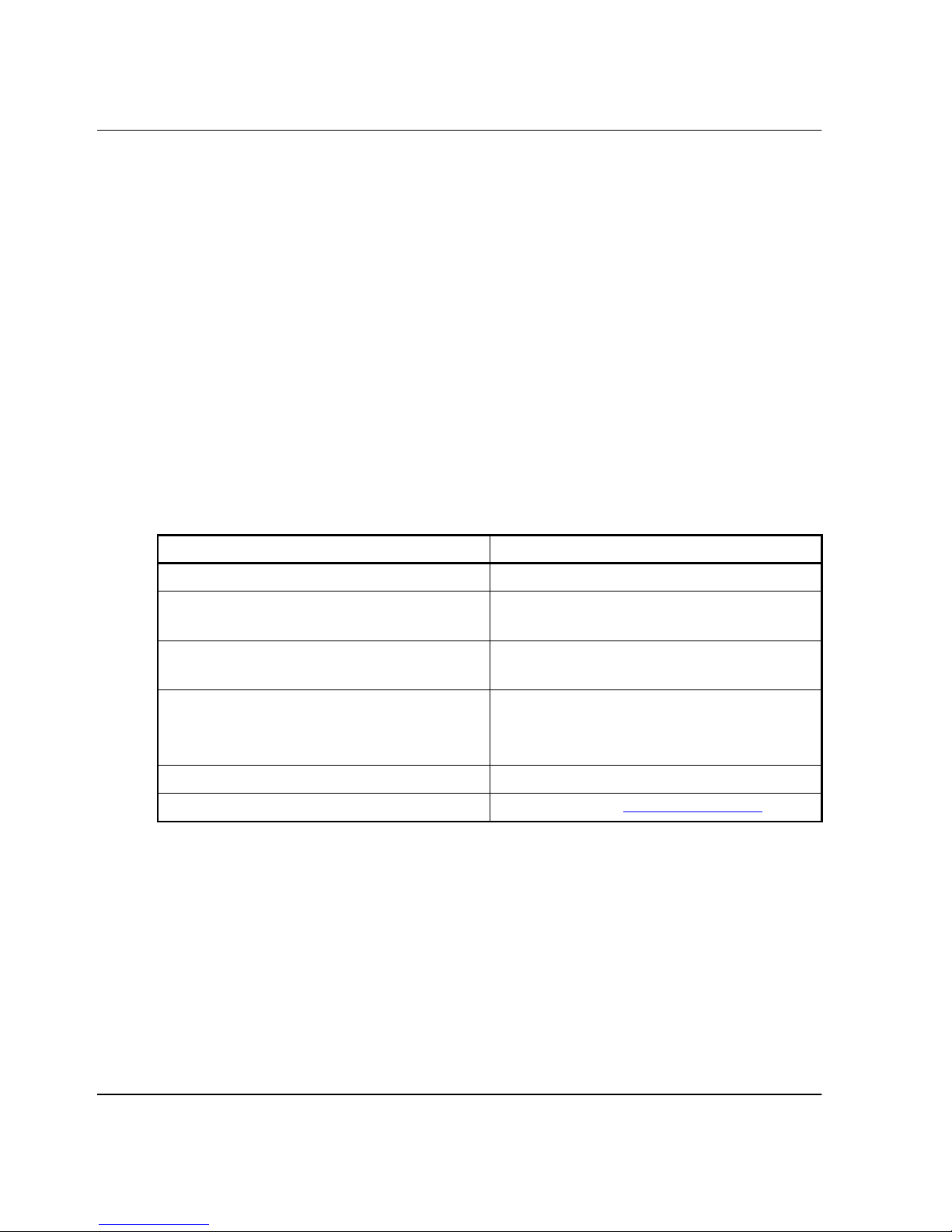
Document Conventions
The conventions included in Table 1 apply.
Table 1: Document Conventions
Element Convention
Cross-reference links Blue text: Figure 1
Key names, menu items, buttons, and
dialog box titles
File names, application names, and text
emphasis
User input, command names, system
responses (output and messages)
Variables
Website addresses Sans serif font (http://thenew.hp.com)
Bold
Italics
Monospace font
COMMAND NAMES
unless they are case sensitive
Monospace, italic font
are uppercase
xiv edge switch 2/16 product manager user guide
Page 11
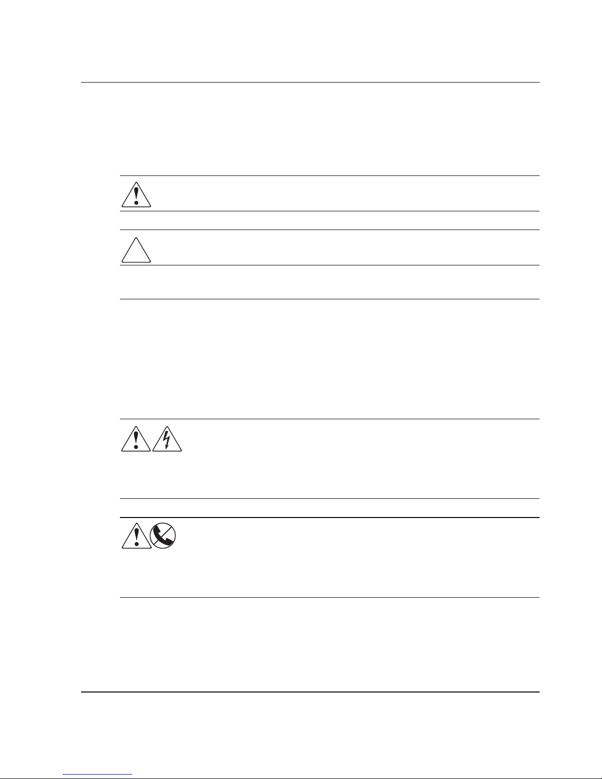
Symbols in Text
These symbols may be found in the text of this guide. They have the following
meanings.
WARNING: Text set off in this manner indicates that failure to follow directions
in the warning could result in bodily harm or loss of life.
CAUTION: Text set off in this manner indicates that failure to follow directions could
result in damage to equipment or loss of information.
IMPORTANT: Text set off in this manner presents clarifying information or specific instructions.
NOTE: Text set off in this manner presents commentary, sidelights, or interesting points of
information.
About This Guide
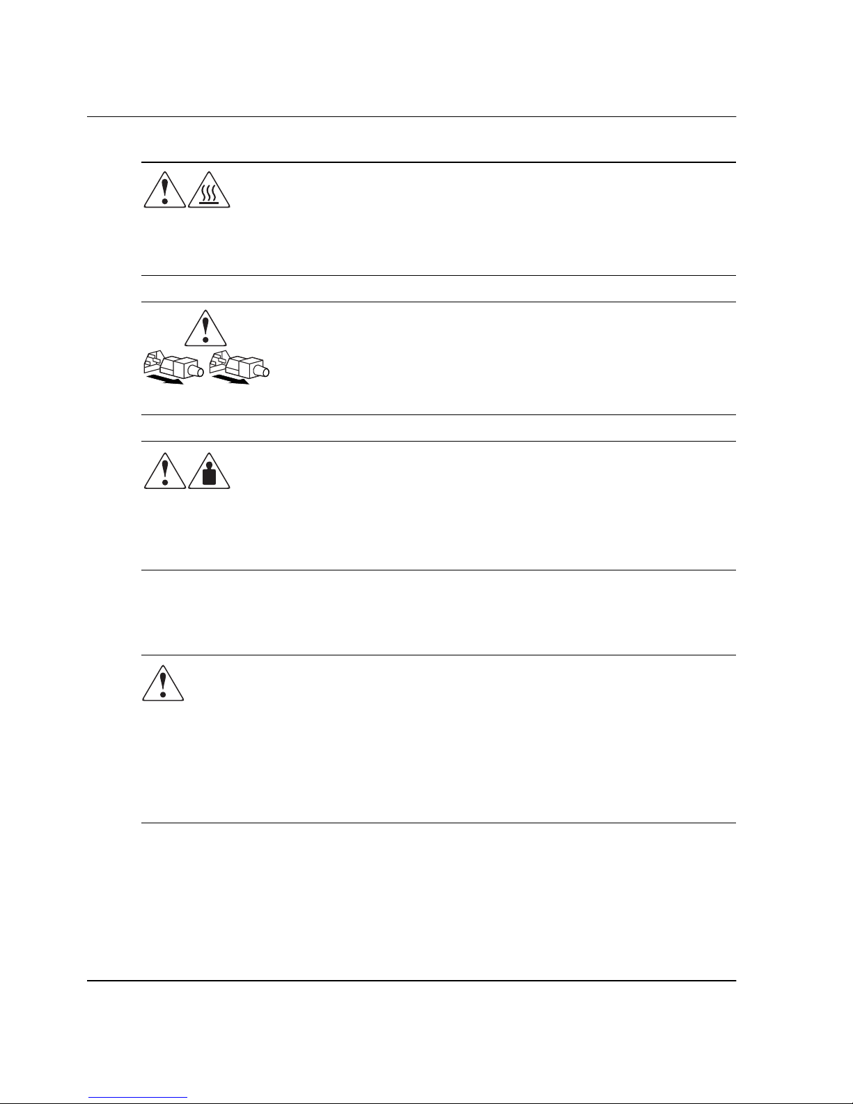
Symbols on Equipment
These icons may be located on equipment in areas where hazardous conditions may
exist.
Any surface or area of the equipment marked with these symbols
indicates the presence of electrical shock hazards. Enclosed area
contains no operator serviceable parts.
WARNING: To reduce the risk of injury from electrical shock hazards, do
not open this enclosure.
Any RJ-45 receptacle marked with these symbols indicates a Network
Interface Connection.
WARNING: To reduce the risk of electrical shock, fire, or damage to the
equipment, do not plug telephone or telecommunications connectors into
this receptacle.
edge switch 2/16 product manager user guide xv
Page 12
About This Guide
Any surface or area of the equipment marked with these symbols
indicates the presence of a hot surface or hot component. If this surface
is contacted, the potential for injury exists.
WARNING: To reduce the risk of injury from a hot component, allow the
surface to cool before touching.
Power Supplies or Systems marked with these symbols indicate the
equipment is supplied by multiple sources of power.
WARNING: To reduce the risk of injury from electrical shock,
remove all power cords to completely disconnect power from the
system.
Any product or assembly marked with these symbols indicates that the
component exceeds the recommended weight for one individual to
handle safely.
Rack Stability
WARNING: To reduce the risk of personal injury or damage to the equipment, be
sure that:
• The leveling jacks are extended to the floor.
• The full weight of the rack rests on the leveling jacks.
• The stabilizing feet are attached to the rack if it is a single rack installations.
• The racks are coupled together in multiple rack installations.
• A rack may become unstable if more than one component is extended for any
reason. Extend only one component at a time.
Getting Help
If you have a problem and have exhausted the information in this guide, you can get
further information and other help in the following locations.
WARNING: To reduce the risk of personal INJURY or damage to the
equipment, observe local occupational health and safety requirements
and guidelines for manual material handling.
xvi edge switch 2/16 product manager user guide
Page 13

HP Technical Support
In North America, call the HP Technical Phone Support Center at
1-800-OK-COMPAQ. This service is available 24 hours a day, 7 days a week.
NOTE: For continuous quality improvement, calls may be recorded or monitored.
Outside North America, call the nearest HP Technical Support Phone Center.
Telephone numbers for world wide Technical Support Centers are listed on the HP
website. Access the HP website by logging on to the Internet at http://www.
Be sure to have the following information available before you call HP:
• Technical support registration number (if applicable)
• Product serial numbers
• Product model names and numbers
• Applicable error messages
• Add-on boards or hardware
About This Guide
hp.com
.
• Third-party hardware or software
• Operating system type and revision level
• Detailed, specific questions
HP Website
The HP website has latest information on this product as well as the latest drivers. You
can access the HP website by logging on to the Internet at
http://www.
hp.com/country/us/eng/prodserv/storage.html
HP Authorized Reseller
For the name of your nearest HP Authorized Reseller:
• In the United States, call 1-800-345-1518.
• In Canada, call 1-800-263-5868.
• Elsewhere, see the HP website for locations and telephone numbers.
.
edge switch 2/16 product manager user guide xvii
Page 14

Page 15

Product Manager Overview
This chapter is an introduction and overview of the hp StorageWorks edge switch 2/16
Product Manager application. It is intended as a quick reference for using features
available through the main Product Manager window.
Managing the StorageWorks Edge Switch 2/16
Three options are available for managing the switch through a user interface:
• The Product Manager application installed on an HAFM server. Access to the
Product Manager must be through the hp StorageWorks ha-fabric manager
(HAFM) application. These applications are installed on the HAFM server.
• The Embedded Web Server (EWS) interface. Using a browser-capable PC with an
internet connection to the switch, you can monitor and manage the switch through
the web server interface embedded in the switch firmware. The interface provides
a GUI similar to the Product Manager application, and supports switch
configuration, statistics monitoring, and basic operation.
1
To launch the web server interface, enter the switch’s IP address as the Internet
uniform resource locator (URL) into any standard browser. Enter a user name and
password at a the login screen. The browser then becomes a management console.
Refer to the web server interface online help for details on use.
NOTE: The default user name for the right to view status and other information is “operator.”
The default user name for the right to modify configuration data, perform maintenance tasks, or
perform other options is “administrator.” The default password for both user names is
“password.”
• The command line interface (CLI). The CLI allows you to access many HAFM
and Product Manager functions while entering commands during a Telnet session
with the switch. The primary purpose of the CLI is to automate management of a
large number of switches using scripts. The CLI is not an interactive interface; no
checking is done for pre-existing conditions and no prompts display to guide users
through tasks. Refer to the hp StorageWorks CLI reference guide for director 2/64,
edge switch 2/16, and edge switch 2/32 (A6534-96027/AA-RQ7AB-TE).
edge switch 2/16 product manager user guide 1–1
Page 16

Product Manager Overview
• Management using simple network management protocol (SNMP). An SNMP
agent is implemented through the SDCM application that allows administrators on
SNMP management workstations to access switch management information using
any standard network management tool. Administrators can assign internet
protocol (IP) addresses and corresponding community names for up to six SNMP
workstations functioning as SNMP trap message recipients.
This manual provides details on the Product Manager application for the edge switch
2/16 only. This manual does not cover the Embedded Web Server Interface.
Management Menu Options
This user’s guide provides information on the edge switch 2/16 Product Manager
application only. Information on the HAFM application is provided in the hp
StorageWorks ha-fabric manager user guide (A6534-96024/AA-RS2CA-TE).
Following are lists of options available under menus in all applications. References
are provided to the correct publication for detailed information on these options.
HAFM
Following are options available through the HAFM. For more information, refer to
Chapter 3 of the hp StorageWorks ha-fabric manager user guide
(A6534-96024/AA-RS2CA-TE).
View Tabs
•Products
•Fabrics
Product Menu
•New
•Open
•Delete
•Modify
• Properties
• Logout
•Exit
1–2 edge switch 2/16 product manager user guide
Page 17

Fabrics Menu
• Rename
• Persist Fabric Topology
• Unpersist Fabric Topology
• Export Fabric Topology
•Show Route
•Hide Route
•Show Zone Members
• Show View Port
• Show Fabric Tree
View Menu
•User Sessions
Product Manager Overview
•Zoom
—In
—Out
—Default
— Fit in View
• Layout Icons
• Circular
•Spring
• Center in Topology
• Clear ISL Alert
• Clear All ISL Alerts
• Enable Fly Over Display
Configure Menu
•Users
•Nicknames
edge switch 2/16 product manager user guide 1–3
Page 18

Product Manager Overview
• Sessions
• SNMP Agent
• Activate Zone Set
• Zoning Library
• Advanced Zoning
Logs Menu
• Audit Log
• Event Log
• Session Log
• Product Status Log
•Fabric Log
Maintenance Menu
• Configure E-Mail
• Test Remote Notification
• Configure Ethernet Events
• Configure Call Home Event Notification
Help
• Contents
• About
Product Manager
Following are options available through the Product Manager application for your
switch. For more information on these options, refer to Menu Bar on page 1-14 in this
manual.
View Tabs
• Hardware
•Node List
1–4 edge switch 2/16 product manager user guide
Page 19

•Port List
• Performance
•FRU List View
Product Menu
• Port (options available when port is selected)
— Port Properties
— Node Properties
— Port Technology
— Block Port
— Enable Beaconing
— Port Diagnostics
—Channel Wrap
Product Manager Overview
—Swap Ports
— Clear Link Incident Alert(s)
— Reset Port
— Port Binding
— Clear Threshold Alert(s)
— Display Options (Nickname and Worldwide Name)
•FRU
— FRU Properties (varies by type of FRU selected)
• Clear System Error Light
• Enable Unit Beaconing
• Properties
•Close
Configure Menu
• Identification
• Operating Mode
edge switch 2/16 product manager user guide 1–5
Page 20

Product Manager Overview
• Operating Parameters
•Ports
• Addresses (S/390 mode only)
— Active
—Stored
• SNMP Agent
• Management Server
• Features
•Date/Time
• Threshold Alerts
• Export Configuration Report
• Enable Web Server
• Enable Telnet
Logs Menu
• Audit Log
• Event Log
• Hardware Log
• Link Incident Log
• Threshold Alert Log
Maintenance Menu
• Port Diagnostics
• Swap Ports (S/390 mode only)
• Data Collection
•IPL
• Set Online State
• Firmware Library
• Enable E-Mail Notification
1–6 edge switch 2/16 product manager user guide
Page 21

• Enable Call Home
• Backup and Restore Configuration
• Reset Configuration
Help Menu
• Contents
• About
Product Manager Description
The Product Manager for the switch is a Java-based graphical user interfaces (GUI)
that provides in-depth management, configuration, and monitoring functions for
individual switches and their field-replaceable units (FRUs). Although the Product
Manager is accessed from the HAFM application, it is a separate application.
In contrast to the Product Manager, the HAFM enables administrators to monitor
operational status for all products and Fibre Channel fabrics managed by an HAFM
server. The HAFM also provides tools to administer user and product access to the
HAFM and Product Manager. Refer to the hp StorageWorks ha-fabric manager user
guide (A6534-96024/AA-RS2CA-TE)
Product Manager Overview
The Product Manager provides graphical views of switch hardware components and
displays of component status. By positioning the cursor on icons, graphics, panels,
and other visual elements in these views and clicking the left or right mouse button,
you can quickly manage and monitor the switch on your network.
Access the switch Product Manager by double-clicking any switch product icon on the
HAFM’s Products View or the Top olo gy tab of the Fabrics View.
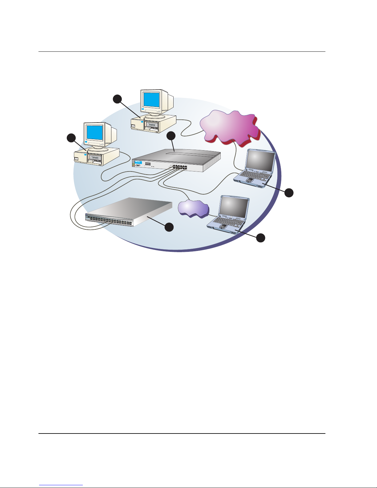
You can install the HAFM and Product Manager applications on remote workstations,
as shown in Figure 1–1, using any standard web browser. For instructions, refer to the
appendix in the hp StorageWorks ha-fabric manager user guide
(A6534-96024/AA-RS2CA-TE) that pertains to the operating system of your
workstation.
edge switch 2/16 product manager user guide 1–7
Page 22
Product Manager Overview
Figure 1–1 illustrates director management components.
1
S
t
o
r
a
g
e
W
o
r
k
s
d
i
r
e
c
t
o
r
2
/
6
4
1
0
/1
0
0
3
1
R
S
T
2
9
7
2
52
2
3
2
1
1
9
0
2
83
2
6
2
4
2
2
2
0
1
8
2
10/100 Mbps
10/100 Mbps
Corporate LAN
Corporate LAN
3
ProCurve10/100
1
2
3
Hub12
4
5
H
6
P
J
3
2
9
Link
4
A
100
7
8
9
10
Power
11
12
Link
100
Fault
Reset
Act
Col
1
2X
3X
Port1Only
4X
5X
6X
MDI-X
MDI
(out)
(in)
7X
8X
9X
10X
11X
12X
4
Internet
Connection
1
7
1
5
3
3579111
6
1
1
41
1
2
P
W
R
0
E
R
R
4681
02
6
1 SNMP management workstation
2 Remote user workstation
3 HP Ethernet hub
4 HAFM server
5 Web browser
6 Switch
Figure 1–1: Switch Management Components on LAN
5
SHR-2314b
1–8 edge switch 2/16 product manager user guide
Page 23

Product Manager Overview
Using the Product Manager, you can:
• Back up and restore configuration data.
• Change operating mode between S/390 and open systems modes.
• Clear the system error indicator.
• Configure extended distance buffering for ports.
• Configure Fibre Channel operating parameters for the switch, such as BB_Credit,
R_A_TOV, E_D_TOV, preferred domain ID, switch priority, and rerouting delay.
• Configure individual ports with a port name describing the node attached to the
port.
• Configure keys for new features.
• Configure interoperability mode for open switch fabrics.
• Configure LIN alerts.
• Configure nickname to display instead of WWN for switch and attached nodes.
• Configure Port Binding.
• Configure port addresses (S/390 mode only)
• Configure SNMP trap recipients and community names.
• Configure Open Systems Management Server features (if installed)
• Configure the switch name, location, description, and contact person.
• Control individual Fibre Channel ports by blocking/unblocking operation,
enabling LIN alerts and WWN binding, setting data speeds, and running internal
and external loopback diagnostics.
• Display field replaceable unit (FRU) properties such as the FRU name, physical
position in the switch (chassis slot number), active failed state, part number, and
serial number.
• Display information for individual Fibre Channel ports, such as the port name,
port number, Fibre Channel address, operational state, type of port, and login data.
• Display information on nodes attached to ports.
• Display port performance and statistics.
• Display vital product data for the switch, such as the system name, description,
contact person, location, status, model number, firmware and EC level, and
manufacturer.
edge switch 2/16 product manager user guide 1–9
Page 24

Product Manager Overview
• Enable beaconing for ports and the switch unit.
• Enable channel wrap mode (S/390 mode only).
• Monitor the operational status of the switch and each of its hardware
field-replaceable units.
• Perform an initial program load (IPL).
• Perform maintenance tasks for the switch including maintaining firmware levels,
administering the Call-Home feature, accessing the switch logs, and collecting
data to support failure analysis.
• Reset port operation.
• Run port diagnostics.
• Set the date and time on the switch.
• Swap addresses between ports (S/390 mode).
Using the Product Manager
This section provides a general overview of the Product Manager and its functions.
For details on performing specific tasks and using specific dialog boxes, refer to the
appropriate chapters in this manual.
Keyboard Navigation
Use standard keyboard navigation in dialog boxes. For example, use the Tab , arrow,
and backspace keys to move through dialog box fields and the Enter key to perform
default button functions.
Using Dialog Boxes
Buttons such as OK, Activate and Close or Cancel initiate functions in a dialog box.
There is a difference between the OK and Activate buttons. The OK button saves the
data you entered and closes the dialog box. The Activate button saves the data you
entered without closing the dialog box, unless there is a Close button in which case,
Activate saves the information without closing the box. There is also a difference
between the Close and Cancel buttons. The Close button closes the dialog box and
saves the data you entered. The Cancel button cancels the operation and closes the
dialog box without saving the information you entered.
1–10 edge switch 2/16 product manager user guide
Page 25

Illustrations Used in this Manual
Figures containing HAFM and Product Manager screens in this manual are included
for illustration purposes only. These illustrations may not match exactly what you see
through your server or workstation. Title bars have been removed from the
illustrations and fields in the illustrations may contain different data than in screens
displayed on your system.
Logging Into the HAFM
To open the Product Manager, you must first log into the HAFM.
1. Perform one of the following steps:
• If you are using the HAFM server, the HAFM application automatically starts
when you power on or reboot the HAFM server. If you power on or reboot the
HAFM server and the HAFM login screen displays, skip to step 3 to log in.
• If you are using a remote user workstation, follow steps 2 through 5.
• If the HAFM window displays already, skip to Opening the Product Manager
on page 1-13.
Product Manager Overview
2. Perform one of the following steps if you are using a remote user workstation (a
network PC with a remote client installed) and the HAFM login screen or HAFM
window is not displayed. If the login screen is displayed, go to step 3.
• Start the HAFM and display the login screen by double-clicking the HAFM
icon on the desktop.
Figure 1–2: HAFM icon
The HAFM login screen displays.
• If the HAFM window is open (Figure 1–3) and you need to log in as another
user or access a different HAFM server, select Logout from the product menu
on the menu bar to display the login screen. Go to step 3.
3. When the HAFM login screen displays, enter your user name and password. The
default user name is Administrator and password is password unless changed by
your system administrator.
edge switch 2/16 product manager user guide 1–11
Page 26
Product Manager Overview
NOTE: The default user name for the right to view status and other information is “operator.”
The default user name for the right to modify configuration data, perform maintenance tasks, or
perform other options is “administrator.” The default password for both user names is
“password.”
4. In the HAFM server box on the login screen select the HAFM server where you
want to connect. Note that if you are logging into an HAFM server locally,
localhost is the HAFM server name. Type in the network address of the server if it
is not in the list.
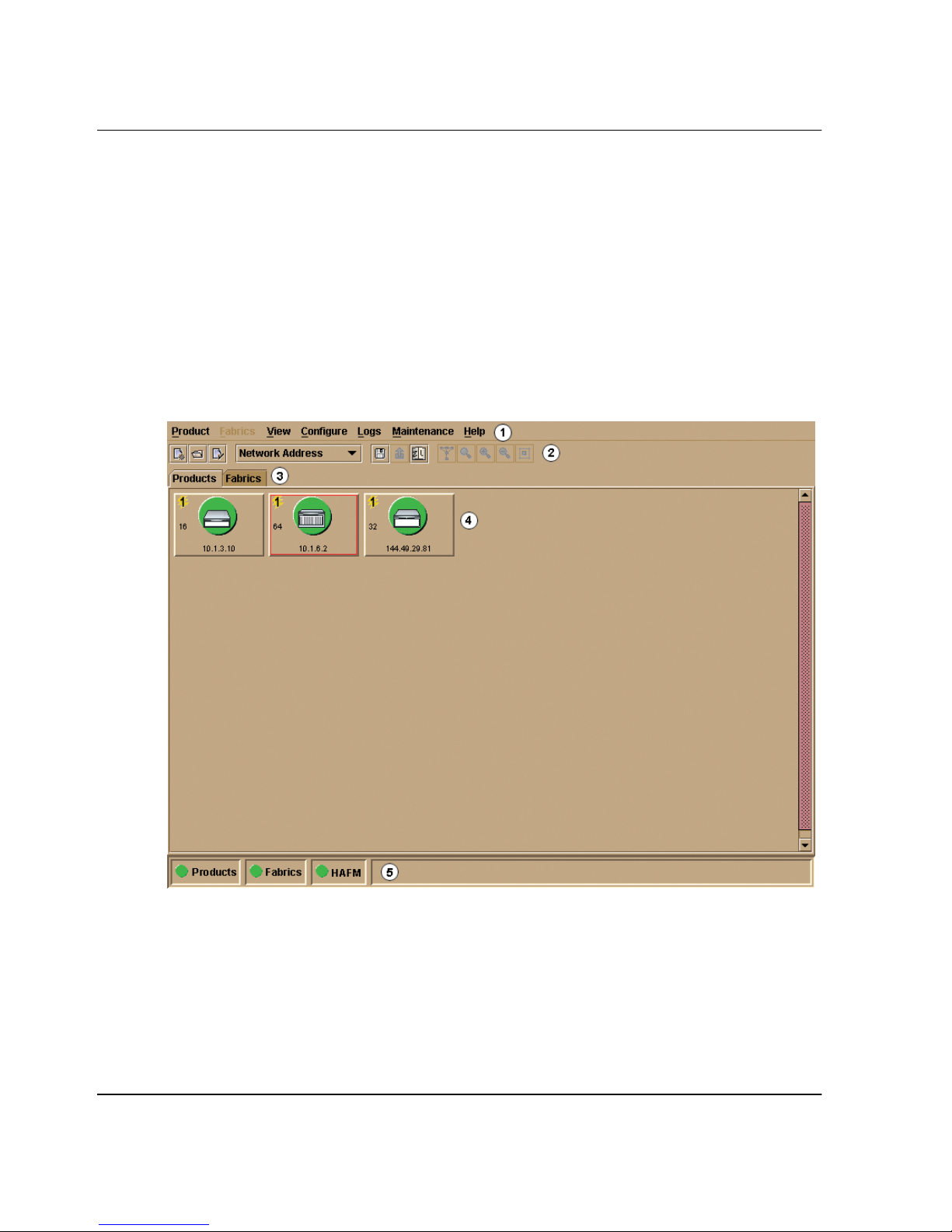
5. Click Activate or press the Enter key on your keyboard. The main HAFM window
displays showing the Product View.
1 Menu Bar
2 Too l B ar
3 View Tabs
Figure 1–3: Main HAFM window (Product View)
1–12 edge switch 2/16 product manager user guide
4 Main Panel
5 Status Panel
Page 27
Opening the Product Manager
To open the Product Manager, double-click the product icon in the Product View or
right-click the icon and select Open.
Figure 1–4: Edge Switch 2/16 icon
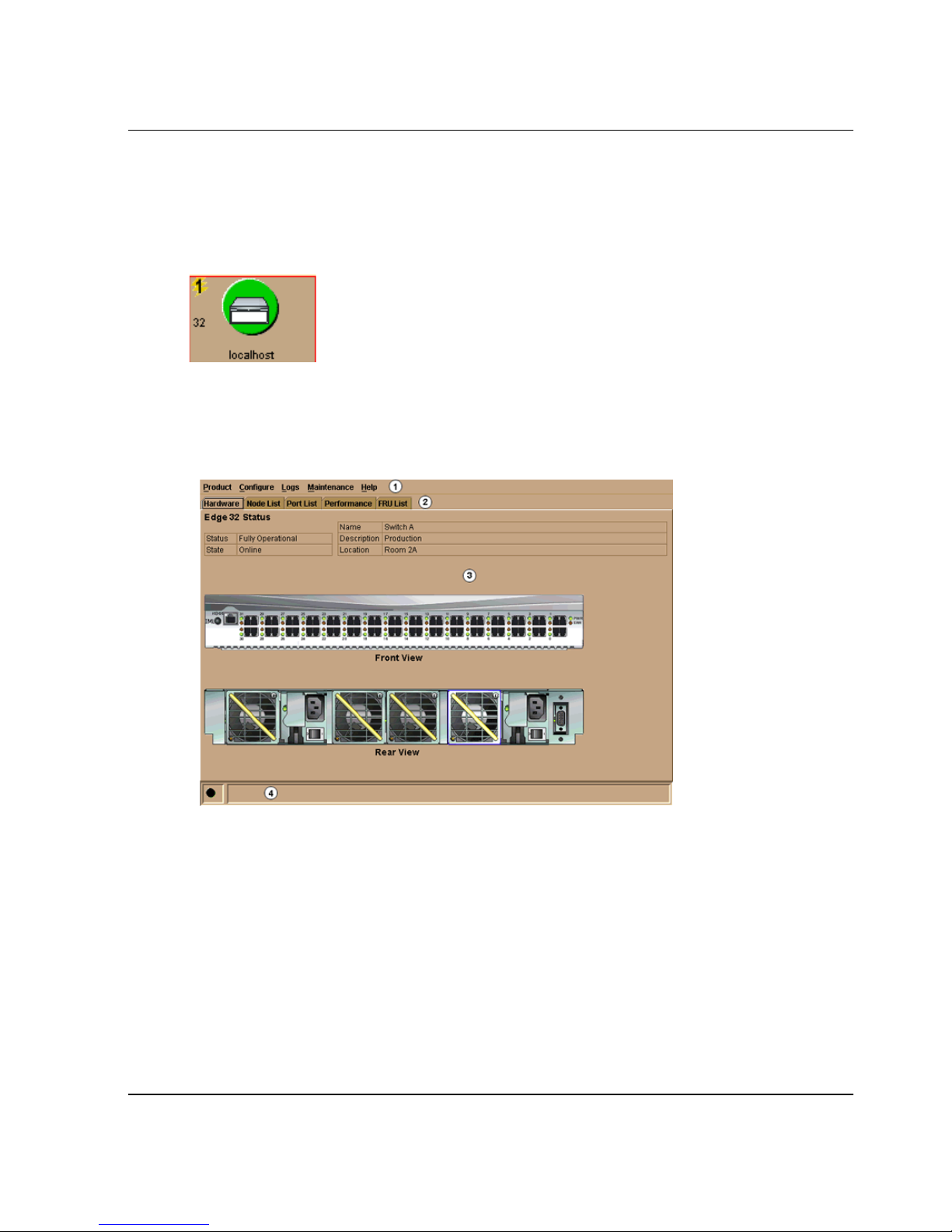
The Product Manager displays showing the default Hardware View. Figure 1–5 shows
the edge switch 2/16 Hardware View.
Product Manager Overview
1 Menu Bar
2 View Tabs
Figure 1–5: Edge Switch 2/16 Product Manager window (Hardware View)
NOTE: The HAFM window is still available as a separate window. You can drag the Product
Manager window away from the HAFM window and view both windows on your PC desktop or
minimize one or both of them to icons if desired. You can have a maximum of four Product
Manager windows open concurrently.
edge switch 2/16 product manager user guide 1–13
3 View Panel
4 Status Bar
Page 28

Product Manager Overview
Window Layout and Function
The main Product Manager window is divided into four main areas as shown in
Figure 1–5 on page 1-13: menu bar, view tabs, view panel, and status bar. Use features
in these panels to configure switch operation, monitor performance, and access
maintenance features.
Menu Bar
The menu bar on the Product Manager window displays tabs for the following menus:
•Product
• Configure
•Logs
• Maintenance
•Help
Click one of the tabs to display a list of menu options. Click an option to open a dialog
box that allows you to perform configuration and maintenance tasks and view logs. If
a menu option contains a check box, click in the box to add a check mark and enable a
function. Click a check box containing a check mark to remove the check mark and
disable the function.
Product Menu
Select one of the following options from the Product menu.
Port
This provides a secondary port menu only when the Hardware View, Port List
View, or Performance View displays in the view panel. To use this menu for a
specific port, click a port in the Hardware View, a port’s row in the Port List View,
or a port’s bar graph in the Performance View. The menu contains options which
are identical to those that display when you right-click the port, port row, or port
bar graph in those views. For detail on these options refer to Port Menu on
page 2-17.
FRU
Click a power supply module or cooling fan module in the Hardware View only
and select FRU from the Product menu to display the FRU Properties menu
option. These displays the properties dialog box for the FRU. The FRU Properties
1–14 edge switch 2/16 product manager user guide
Page 29

Product Manager Overview
dialog box can also be displayed when you double-click the FRU in the Hardware
View. For details on these options refer to Displaying FRU Information on
page 2-7.
Clear System Error Light
Select this to turn off the amber system error LED, located below the green power
LED on the switch front bezel.
Enable Unit Beaconing
Click the check box to toggle unit beaconing on or off. When the check box has a
check mark, unit beaconing is on, and the amber system error light on the switch
front bezel blinks to help users locate the actual unit in an equipment room. When
you click the check box to remove the check mark, unit beaconing is disabled and
the amber LED goes out. You can only enable beaconing if there are no system
errors (the system error light is off).
Properties
Click to display the Switch Properties dialog box. This dialog box contains the
switch name, description, location, and contact person configured through the
Configure Identification dialog box. Also included is other product information as
detailed in switch Properties. You can also display this dialog box by
double-clicking an area on the illustration in the Hardware View, away from a
hardware component.
Close
Select this option to close the Product Manager window.
Configure Menu
Click on the Configure menu on the menu bar to display a menu that lists the
following options. For detailed information on using these options, refer to Chapter 3,
Configuring the Switch.
Identification
Select this option to display the Configure Identification dialog box. Enter the
following information in this dialog box:
edge switch 2/16 product manager user guide 1–15
Page 30

Product Manager Overview
— Name - Assign a product name. Note that you can set this name as the
nickname for the switch’s WWN, using the Set Name as Nickname checkbox.
The nickname then displays instead of the WWN in Product Manager views.
— Description - Assign a unique product description.
— Location - Describe the product’s location.
— Contact - Assign a contact either by name, phone number, or e-mail address.
NOTE: This information displays in the identification table at the top of the Hardware View and
in the HAFM Product View, if the Product View is configured to display names.
Operating Mode
NOTE: The switch must be offline before you change operating modes.
Select this option to display the Configure Operating Mode dialog box. Use this
dialog box to configure either S/390 or open systems mode, as well as
interoperability mode options. Open system or S/390 modes allow you to use
Product Manager menu options, dialog boxes, and features that are the most
useful when attaching to either IBM S/390 Enterprise servers or open systems
devices. If you enable open systems mode, you can then select the appropriate
interoperability mode to work with the multiswitch fabric. Refer to Configure
Operating Mode on page 3-2 for instructions.
NOTE: If the FICON Management Server feature is enabled, the default mode will be S/390.
You can only enable one Management Server feature at a time, either FICON Management
Server or Open Systems Management server.
Operating Parameters
Select this option to display the Configure Operating Parameters dialog box for
setting Fibre Channel operating parameters. In this dialog box, you can set
buffer-to-buffer credit (BB_Credit) from 1 to 60 (default is 16). You can also set
the resource allocation time-out value (R_A_TOV) and error detect time-out
value (E_D_TOV) in tenth-of-a-second increments, as well as other fabric
operating parameters, such as preferred domain ID (1 to 31) and switch priority
level (Principal, Default, or Never Principal). You must take the switch offline
through the Set Online State dialog box to configure these parameters. In addition,
you can also enable the rerouting delay feature. Refer to Configure Operating
Parameters on page 3-4 for more information on configuring the switch priority
and rerouting delay.
1–16 edge switch 2/16 product manager user guide
Page 31

Product Manager Overview
Ports
Select this option to display the Configure Ports dialog box. This dialog box has
different functions in S/390 versus open systems mode.
In S/390 mode, use the dialog box to enable extended distance buffering for 10 to
100 km, link incident (LIN) alerts, and port binding for each port.
In open systems mode, for each port you can provide a name, block or unblock
operation, configure extended distance buffering for 10 to 100 km, enable LIN
alerts for each port, define a type (G, F, and E), and enable port binding.
NOTE: Ports are automatically configured as G_Ports if no device is connected, F_Ports if a
device is connected, and E_Ports if a switch is connected.
In both modes, you can also enable the rerouting delay feature.
Addresses
S/390 mode only. Select from two suboptions for active and stored addresses.
Active Addresses. Displays the Configure-Addresses - “Active” dialog box. Use
this dialog box to configure a name, blocked or unblocked state, and prohibited
and allowed connection attributes for a port.
Stored Addresses: Displays the Address Configuration Library. Use this dialog
box to activate, modify, and delete existing address configurations created through
the Active Addresses dialog box.
SNMP Agent
Select this option to display the Configure SNMP dialog box. Use this dialog box
to configure network addresses and community names for up to six SNMP trap
recipients. Also authorize write permissions to enable SNMP management
stations to modify writable MIB variables. In addition, you can enable
authorization traps to be sent to management stations when unauthorized stations
request access to switch SNMP data.
Management Server
Select this option to display either the Configure Open Systems Management
Server or Configure FICON Management Server dialog box, depending on which
feature (if any) in enabled for the switch. Use this to configure a FICON or open
systems inband management program to function with the switch. To use these
procedure, you must have enabled either the FICON Management Server or Open
Systems Management Server through the Configure Feature Key dialog box.
edge switch 2/16 product manager user guide 1–17
Page 32

Product Manager Overview
Features
Displays the Configure Feature Key dialog box. Use this dialog box to enter a
feature key to enable optional features that you have purchased for the switch.
NOTE: The Configure Feature is not supported in this software version.
Date and Time
Select this option to display the Configure Date and Time dialog box. Use this
option to set the current date and time in the switch. When the Periodic Date/Time
Synchronization check box is checked, the Date and Time fields are greyed out
(disabled), and the HAFM server date and time periodically synchronizes the
switch date and time. If the Periodic Date/Time Synchronization check box is not
checked, you can set the date and time in the dialog box fields manually.
Threshold Alert(s)
Select this option to configure threshold alerts for ports. A threshold alert notifies
users when the transmit (Tx) or receive (Rx) throughput reaches specified values
for specific switch ports or port types (E_Ports or F_Ports). Using this option, you
can configure:
— A name for the alert.
— A threshold type for the alert (Rx, Tx, or either).
— Active or inactive state of the alert.
— Threshold criteria. This includes configuring the threshold as the percent of
port traffic capacity utilized (% utilization). You must also configure the time
interval during which the throughput is measured and the maximum
cumulative time that the throughput percentage threshold can be exceeded
during this time interval before an alert is generated.
Export Configuration Report
Select this option to display the Export Configuration Report dialog box, which
enables you to specify a file name in which to save an ASCII text file containing
all current user-definable configuration options in a printable format. Note that
this file cannot be read back into the Product Manager in order to set configuration
parameters.
1–18 edge switch 2/16 product manager user guide
Page 33

Product Manager Overview
Enable Web Server
Select this option place a check mark in the check box to enable the Embedded
Web Server interface on the switch. Select the option again to remove the check
mark and disable the Embedded Web Server interface. When disabled, users at
remote workstations cannot access the interface. If enabled, hp recommends
changing the user names and/or passwords from the default values to prevent
unauthorized access.
Enable Telnet
Select this option place a check mark in the check box to enable telnet access to
the switch. Select the option again to remove the check mark and disable telnet
access. When disabled, users at remote workstations cannot access the switch
through telnet to use the Command Line Interface (CLI) or perform other tasks. If
enabled, hp recommends changing the user names and/or passwords from the
default values to prevent unauthorized access.
Logs Menu
Click on the Logs menu from the menu bar to display a menu that lists the following
options. For detailed information on using these dialog boxes, refer to Chapter 4,
Using Logs.
Audit Log
This log provides a record of all configuration changes made on the switch. Each
entry displays the date and time of the change, a description of the change, the
source of the change (such as the HAFM server or SNMP management station),
and an identifier for the source, such as the IP address of the HAFM server or
SNMP management station.
Event Log
Select this option to display the switch event log. This log provides a record of
significant events that have occurred on the switch, such as hardware failures,
degraded operation, and port problems. Each entry includes the date and time of
the event, a reason code for the event, the severity level, a brief description, and
up to 32 bytes of supplementary event data. Refer to the hp StorageWorks edge
switch 2/16 service manual (A7284-96002/AA-RS2JA-TE) for more information.
edge switch 2/16 product manager user guide 1–19
Page 34

Product Manager Overview
Hardware Log
This log displays information on FRUs inserted and removed from the switch.
Each log entry includes the name of the FRU inserted or removed, the slot
position relative to identical FRUs installed, whether the FRU was inserted or
removed, the FRU part number and serial number, and the date and time the FRU
was inserted or removed.
Link Incident Log
The link incident (LIN) log displays the most recent incidents with their date and
time, port number, and description of the incident. A link incident can be one of
several conditions detected on a fiber optic link. For a list of events that may cause
a link incident to be written to the log, refer to Link Incident Log on page 4-7.
Threshold Alert Log
This log provides notifications of threshold alerts. Besides the date and time that
the alert occurred, it also displays information that was configured through the
Configure Threshold Alert(s) option under the Configure menu. This includes the
alert name, port for which the alert is configured, the type of alert (transmit
throughput, receive throughput, or both), threshold utilization of traffic capacity,
minutes the threshold was configured for, and the configured time interval for the
threshold. For more details on this log, refer to Threshold Alert Log on page 4-8.
Maintenance Menu
Click on the Maintenance menu on the menu bar to display a list of the following
options. For detailed information on using these dialog boxes, refer to Chapter 5,
Using Maintenance Features.
Port Diagnostics
This option displays the Port Diagnostics dialog box. Use this dialog box to run
internal and external loopback tests on ports. Refer to the hp StorageWorks edge
switch 2/16 service manual (A7284-96002/AA-RS2JA-TE) for instructions.
Swap Ports
S/390 mode only. Select this option to display the Swap Ports dialog box. Use this
dialog box to swap one port address for another.
1–20 edge switch 2/16 product manager user guide
Page 35

Product Manager Overview
Data Collection
This option displays the Save Data Collection dialog box. Use this dialog box to
collect maintenance data into a file. This file is used by support personnel to
diagnose system problems. Refer to the hp StorageWorks edge switch 2/16 service
manual (A7284-96002/AA-RS2JA-TE) for instructions.
IPL
Select this option to initiate an initial program load on the switch. A dialog box
displays to allow you to confirm the IPL. Note that an IPL does not affect any
configuration settings done through the Product Manager. Port operation is
interrupted during the IPL.
Refer to the Execute an IPL on page 5-2 for more information.
Set Online State
Select this option to display the Set Online State dialog box. Use this dialog box to
change the online state of the switch to offline or online.
Firmware Library
Select this option to display the Firmware Library dialog box. This dialog box
displays all firmware versions currently installed on the HAFM server that can be
downloaded to switches. Use this dialog box to add a new firmware version to the
HAFM server hard disk, modify the description displayed for an existing version,
delete a version from the PC, or download (send) a version for operation on a
switch. For additional information on using this option, refer to the hp
StorageWorks edge switch 2/16 service manual (A7284-96002/AA-RS2JA-TE).
Enable E-Mail Notification
The Simple Mail Transfer Protocol (SMTP) server and e-mail recipient addresses
are configured in the HAFM application (not in the switch’s Product Manager).
E-mail notification is also initially enabled in the HAFM for all switches managed
by the HAFM. Note, however, that the E-Mail Notification option on the Product
Manager’s Maintenance menu must be enabled (checked) for e-mail notification
to occur for the specific switch.
The default setting for the Enable E-Mail Notification function is enabled
(checked). To disable the function, select Enable E-Mail Notification from the
Maintenance menu to clear the check box.
edge switch 2/16 product manager user guide 1–21
Page 36
Product Manager Overview
For additional information on using this option, refer to Enable E-Mail
Notification on page 5-5.
Enable Call Home Notification
NOTE: The default setting for the Enable Call Home Notification function is disabled
(unchecked).
Select Enable Call Home Notification from the Maintenance menu to enable the
call-home function for the switch.
The parameters of the call-home feature are configured in Windows. Refer to the
hp StorageWorks HAFM server installation guide (A6582-96001/AA-RT4KA-TE)
for instructions.
Backup & Restore Configuration
Select this option to save the product configuration stored on the switch to the
HAFM server hard disk or to restore the configuration data from the HAFM
server. Only a single copy of the configuration is kept on the server.
This backup is primarily for restoring the configuration data to a replacement
switch. You cannot modify the location or the file name of the saved
configuration. (Note that the CTP card is not a FRU. If it fails, the switch must be
replaced.)
For additional information on using this option, refer to Backing Up and Restoring
Configuration Data on page 3-37.
Reset Configuration
Select this option to reset all switch configuration data back to the factory
defaults. A confirmation dialog box displays with a warning upon selecting the
option. For additional information on using this option, refer to Reset
Configuration on page 5-8.
WARNING: This operation resets all configuration including any optional
features that have been installed. You will need to re-enter your feature key to
enable all optional features after resetting the configuration.
Help Menu
Click on the Help menu on the menu bar to display a list of the following options.
1–22 edge switch 2/16 product manager user guide
Page 37

Contents
About
View Tabs
Click one of the view tabs across the top of the Product Manager window to display
the following views in the View panel.
• Hardware
•Node List
Product Manager Overview
Select this option to display the Help window. The Help window contains
Contents, Index, and Glossary buttons and hypertext-- linked items to help you
quickly navigate through information. Use the forward (>) and back (<) buttons to
scroll forward and backward through the displayed help frames. Exit the help
feature at any time by clicking the Close icon at the top of the Help window.
Select this option to display the version number for the Product Manager and
copyright information.
•Port List
• Performance
•FRU List
View Panel
Views, selected from the view tabs, display under the tabs in the view panel.
Hardware View
The Hardware View is the default view that displays in the view panel when you open
the switch Product Manager. To return to this view from another view, click the
Hardware View tab. Refer to Figure 1–5 on page 1-13 for an example of this view.
In the Hardware View, colored indicators reflect the status of actual LEDs on the
switch FRUs. The status bar displays a symbol to represent the most degraded status
currently reported by any of the switch FRUs. For example, for a port failure,
indicated by a blinking red and yellow diamond on a port, a yellow triangle displays
on the status bar to indicate a degraded condition. However, if a blinking red and
yellow diamond displays over both power supplies, the status bar displays a blinking
red and yellow diamond, which indicates a failure requiring immediate attention. For
edge switch 2/16 product manager user guide 1–23
Page 38

Product Manager Overview
an explanation of the different status symbols and the reasons they display in the
Hardware View or Port List View, refer to the table under Monitoring Hardware
Operation on page 2-4.
Switch Menu
Double-click the switch graphic away from a FRU to display the Switch Properties
dialog box. Right-click a hardware graphic away from a FRU to display the following
options:
• Switch Properties
• Enable Unit Beaconing
• Clear System Error Light
• IPL Switch
• Set Switch Date and Time
• Set Switch Online State
For details on menu options, refer to Switch Menu on page 2-14.
For details on navigating and monitoring via the Hardware View, refer to Hardware
View on page 2-1.
Port Menu
Double-click a port to display the Port Properties dialog box. Right-click a port to
display the following options:
• Port Properties
• Node Properties
• Port Technology
• Block Port
• Enable Beaconing
• Channel Wrap (S/390 mode only)
• Swap Ports (S/390 mode only)
• Port Diagnostics
• Clear Link Incident Alert(s)
•Reset Port
1–24 edge switch 2/16 product manager user guide
Page 39
Product Manager Overview
• Port Binding
• Clear Threshold Alert(s)
Note that these same options are available when you click a port on the Hardware
View and select the port secondary menu from the Product menu on the menu bar.
NOTE: For Node Properties, if a node is not logged in a message box displays indicating that
node information is not available.
For details on menu options, refer to Port Menu on page 2-17.
For details on navigating and monitoring via the Hardware View, refer to Hardware
View on page 2-1.
Port List View
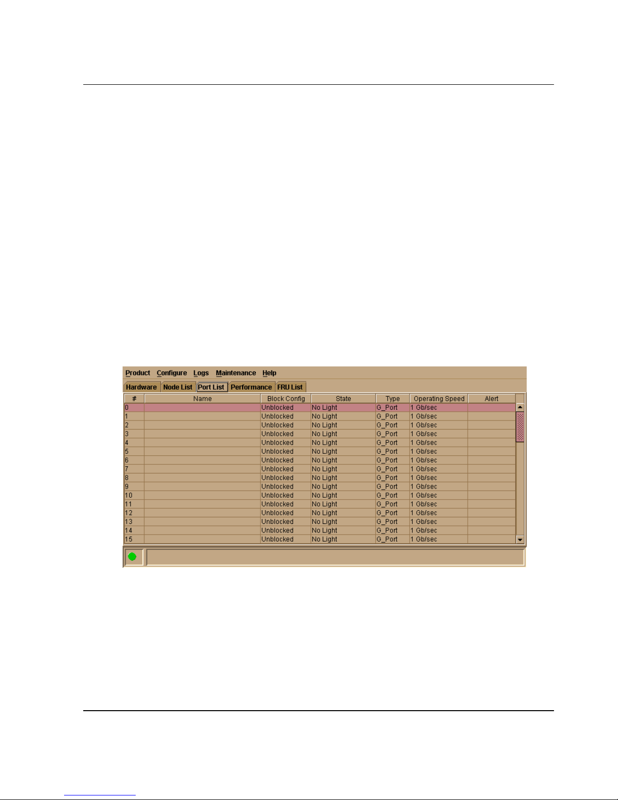
Select the Port List View tab. A table listing the port number, port name, port address
(S/390 mode only), the block/unblock configuration, operating state, port type,
operating speed, and alert condition displays in the view panel. Figure 1–6 shows an
example of the Port List View.
Figure 1–6: Port List View
The Port List View displays information about all ports installed in the switch. All data
is dynamic and updates automatically. Double-click any row in this view to display
the Port Properties dialog box for the port.
edge switch 2/16 product manager user guide 1–25
Page 40

Product Manager Overview
Right-click a port row to display the same menu options that display when you
right-click a port in the Hardware View or a port’s bar graph in the Performance View.
These include:
• Port Properties
• Node Properties
• Port Technology
• Block Port
• Enable Beaconing
• Channel Wrap (S/390 mode only)
• Swap Ports (S/390 mode only)
• Port Diagnostics
• Clear Link Incident Alert(s)
•Reset Port
• Port Binding
• Clear Threshold Alert(s)
Note that these options are also available when you click a port row and select the
Port secondary menu from the Product menu on the menu bar.
For details on these menu options, refer to Port Menu on page 2-17.
For details on navigating and monitoring via the Port List View, refer to Port List View
on page 1-25.
FRU List View
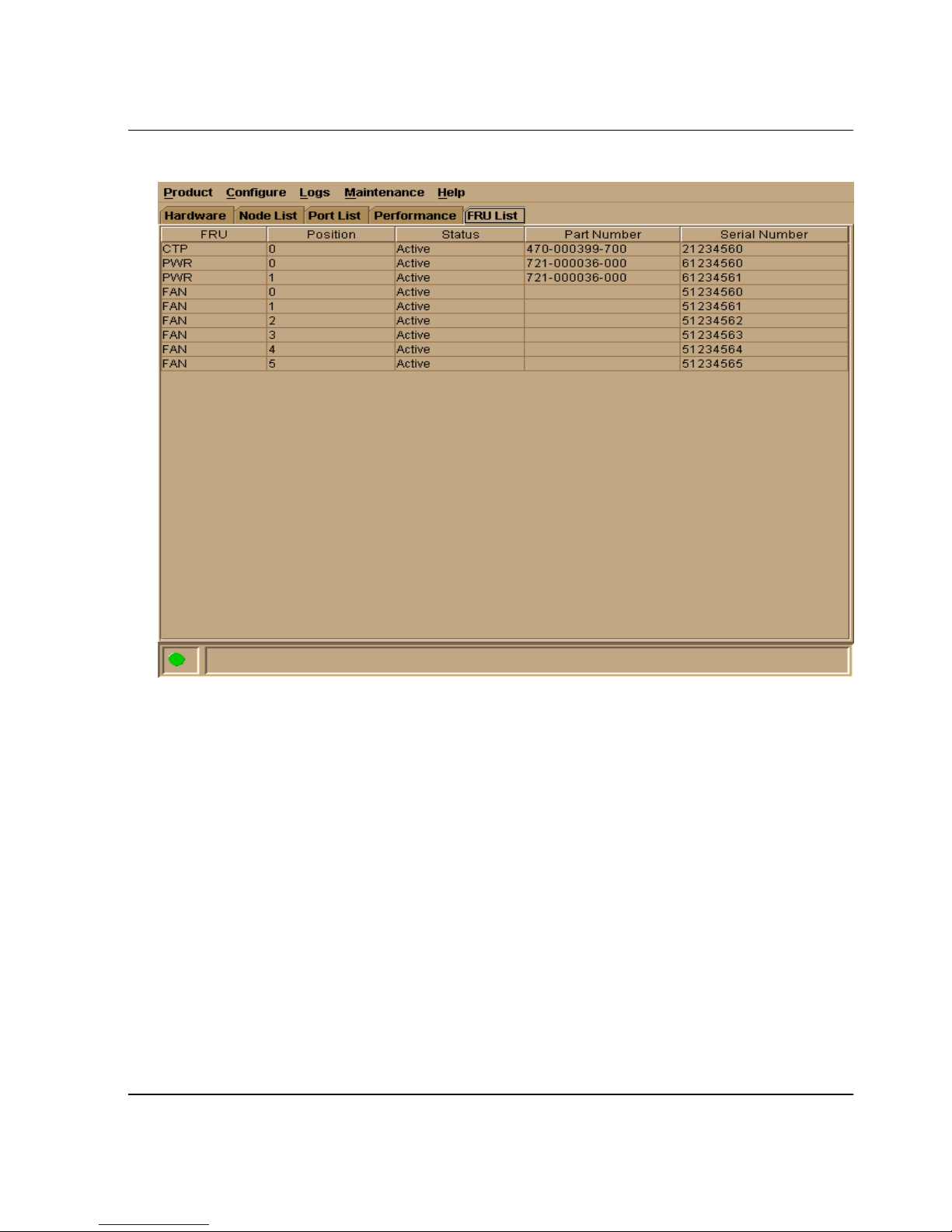
Select the FRU List view tab. A table with information about each of the FRUs
installed in the switch displays in the view panel. All data is dynamic and updates
automatically. Figure 1–7 shows an example of the FRU List View.
1–26 edge switch 2/16 product manager user guide
Page 41
Product Manager Overview
Figure 1–7: FRU List View
For details on navigating and monitoring via the FRU List View, refer to FRU List
View on page 2-24.
Node List View
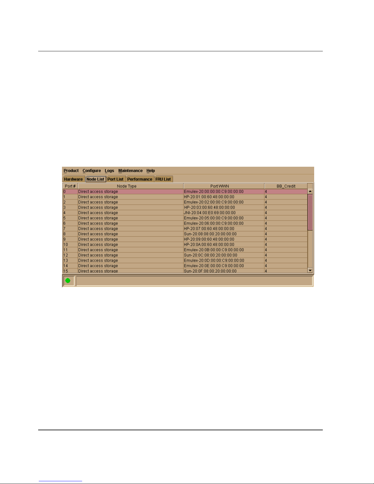
Select Node List from view tabs. Figure 1–8 on page 1-28 shows an example of the
Node List View. This view displays a table with information about all node
attachments or N_Ports that have logged into existing F_Ports on the switch. Only
N_Ports display in the Node List View after nodes have logged in to the fabric. The
columns that display in the table include: port number where the node is attached, the
port’s address (S/390 mode only), node type, WWN of the attached node (device), and
BB_Credit used by the attached node.
Double-click a port row to highlight it and display the Node Properties dialog box for
that port.
edge switch 2/16 product manager user guide 1–27
Page 42
Product Manager Overview
Right-click a port row to display the following menu options:
• Node Properties: Displays the Node Properties dialog box.
• Port Properties: Displays the Port Properties dialog box.
• Define Nickname. Displays the Define Nickname dialog box, where you can
define a nickname to display for the attached device instead of the device's 8-byte
WWN.
• Display options. Allows you to display attached devices listed under the Port
WWN column in the Node List View by the device’s nickname configured through
the Define Nickname menu option or the device's WWN.
Figure 1–8: Node List View
Note that these options are also available when you click a port row, then select the
Port secondary menu from the Product tab on the menu bar.
For details on navigating and monitoring via the Node List View, refer to Node List
View on page 1-27.
Performance View
Select the Performance view tab. Figure 1–9 shows an example of the Performance
View. This view provides a graphical display of performance for all ports. The top
portion of the Performance View displays bar graphs that show the level of
transmit/receive activity for each port. This information updates every five seconds.
Each bar graph also shows the percentage link utilization for the port. A red arrow
1–28 edge switch 2/16 product manager user guide
Page 43
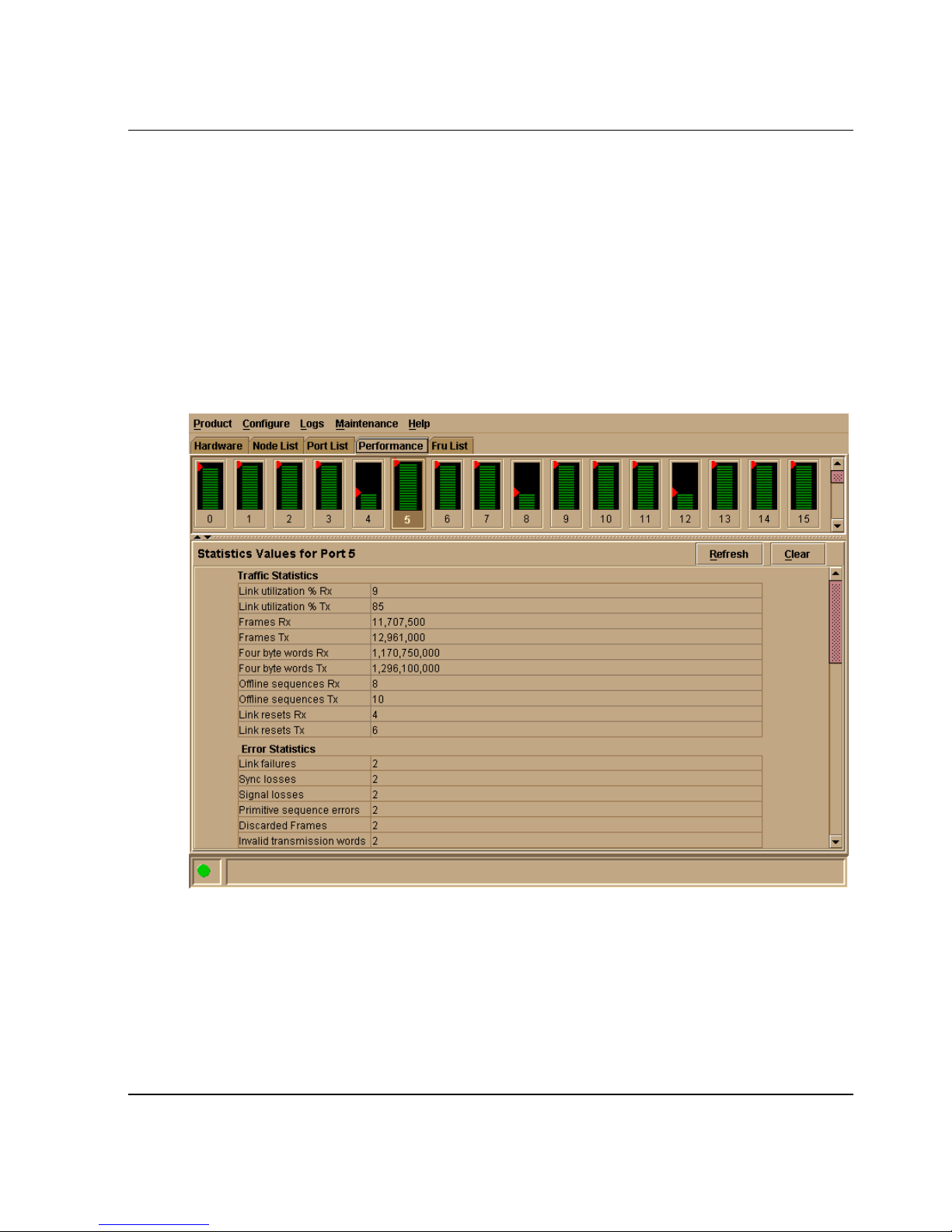
Product Manager Overview
marks the highest utilization level reached since the Performance View was opened. If
the system detects activity on a port, it represents minimal activity with at least one
bar.
When an end device (node) is logged into a port, moving the cursor over the port’s bar
graph in the Performance View highlights the graph and displays a message with the
world-wide name of the connected node. If the connected node has more than one
port, this is the world-wide name of the specific port on the node. When a port is
functioning as an expansion port (E_Port), the message is “E_Port.” When a port is
not logged into an end-device (not functioning as an F_Port) or to another switch (not
functioning as an E_Port), the message is the port’s current online state.
Figure 1–9: Performance View
Right-click a bar graph to display a menu of port-related actions. The options
available on this menu are the same as those that are available when you right-click a
port in the Hardware View or right-click a row in the Port List View. These include:
• Port Properties
edge switch 2/16 product manager user guide 1–29
Page 44

Product Manager Overview
• Node Properties
• Port Technology
• Block Port
• Enable Beaconing
• Port Diagnostics
• Channel Wrap (S/390 mode only)
• Swap Ports (S/390 mode only)
• Clear Link Incident Alert(s)
•Reset Port
• Port Binding
• Clear Threshold Alert(s)
Note that these same options are also available when you click a port’s graph, then
select the Port secondary menu from the Product menu on the menu bar.
For details on menu options, refer to Port Menu on page 2-17.
The bottom portion of the Performance View displays cumulative statistical
information for the port selected in the bar graph. Click the Refresh button to update
the data with current data from the port.
Click the Clear button to clear all of the counters to zero for the selected port and to
place an entry in the audit log indicating that statistics for the port have been cleared.
NOTE: Clearing the counters clears the statistics for all users.
For more information about the Performance View, including statistics descriptions,
refer to Performance View on page 2-31.
Status Bar
The status bar is located along the bottom of the Product Manager window. This
includes a symbol that displays at the left side of the bar and messages that display in
the panel to the right of the symbol. The symbol indicates the current operating status
of the switch and the messages display to provide more description of menu options as
you move the cursor over the options under menu bar menus. Refer to Table 1–1 on
page 1-31 for the meaning of these status symbols and of the corresponding alert text
that displays in the Edge-16 Status table at the top of the Hardware View in the view
panel.
1–30 edge switch 2/16 product manager user guide
Page 45
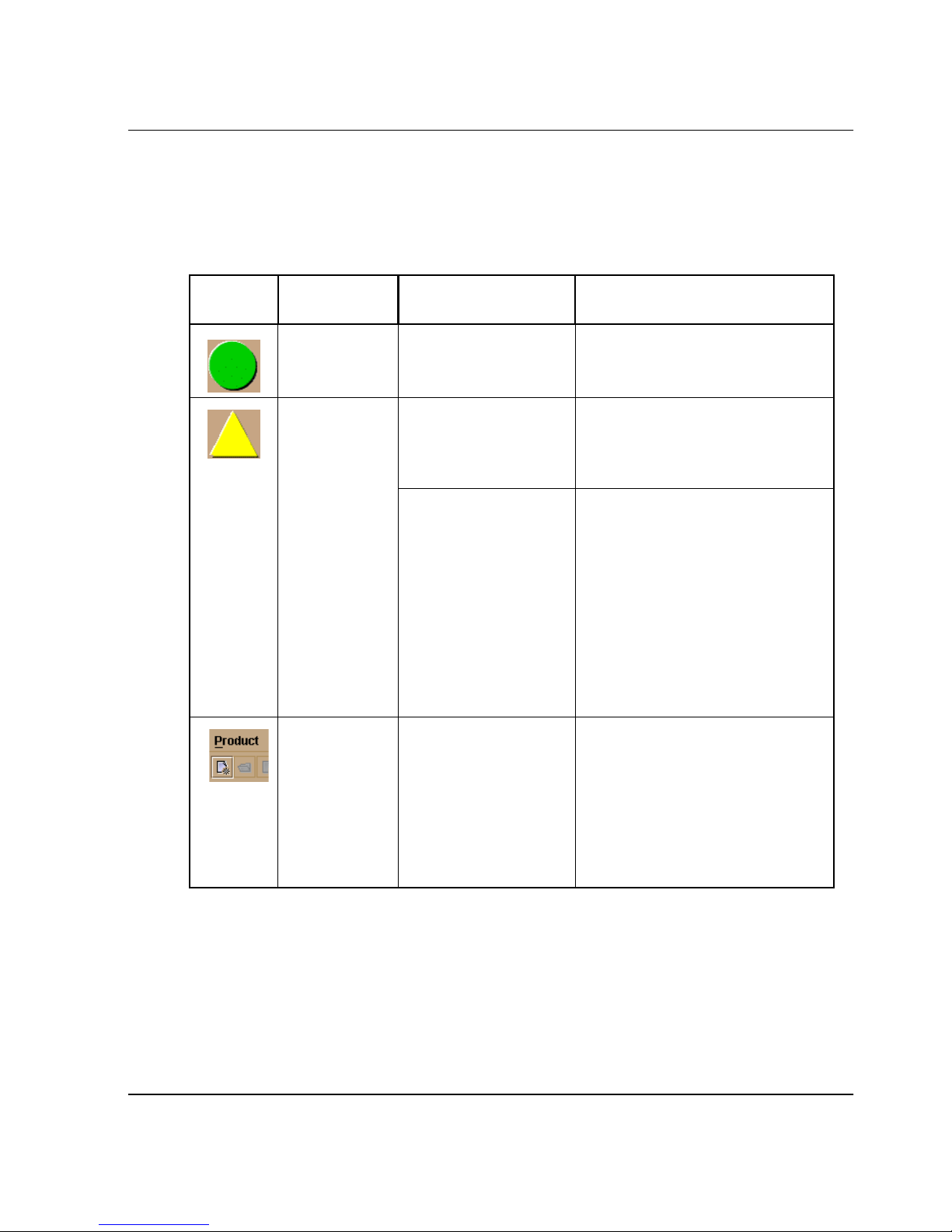
Product Manager Overview
If a gray square displays in the status bar (no Ethernet connection), a reason for the
status displays in the Status table at the top of the Hardware View. Refer to No Link
Status on page 2-2 for details.
Table 1–1: Operating Status - Status Bar and Switch Status
Switch Status
Symbol Status Bar
Green Circle Fully Operational All components and installed
Table Text Meaning
ports are operational; no
failures.
Yellow
Triangle
Red
Diamond
with Yellow
Background
Redundant Failure A redundant component has
failed, such as a power supply,
and the backup component
has taken over operation.
Minor Failure A failure occurred which has
decreased the switch
operational ability. Normal
switching operations are not
affected.
• One or more ports failed,
but at least one port is still
operational.
• A fan has failed or is not
rotating sufficiently.
Not Operational A critical failure prevents the
switch from performing
fundamental switching
operations.
• All fans failed.
• All installed ports failed.
• Both power supplies failed.
edge switch 2/16 product manager user guide 1–31
Page 46
Product Manager Overview
Table 1–1: Operating Status - Status Bar and Switch Status (Continued)
Symbol Status Bar
Switch Status
Table Text Meaning
Gray Square Never Connected
Link Timeout
Protocol Mismatch
Duplicate Session
Unknown Network
Address
Incorrect Product
Type
Messages display to the right of the status symbol as you move the cursor over options
under the menu bar menus. These messages provide additional details about tasks that
you can perform through the menu option.
Closing the Product Manager
To close the Product Manager, use the following steps:
1. To close the Product Manager, do one of the following:
• Select Close from the Product menu on the menu bar.
• Click the X button at the top right corner of the Product Manager window.
switch status is unknown. This
occurs if the Ethernet network
connection between the
HAFM server and the switch
cannot be established or if the
CTP fails. Refer to No Link
Status on page 2-2 for details
on the status table text.
• Double-click the icon at the top left corner of the Product Manager window,
or right-click the icon and select Close from the menu that displays.
2. Select Logout or Exit from the Product menu in the HAFM application.
• If you select Logout, the StorageWorks ha-fabric manager Login dialog box
displays. You can now log in again using a user name and password. Log into
a different HAFM server by selecting a different server from the HAFM
server box.
• If you select Exit, the Product View window closes.
User Rights
The HAFM’s system administrator can assign levels of access, or “User Rights,” to
Product Manager users through the HAFM application.
1–32 edge switch 2/16 product manager user guide
Page 47
Product Manager Overview
NOTE: Note that the HAFM’s system administrator only has view rights while operating in a
specific Product Manager application. Conversely, a Product Manager’s product administrator
only has view rights while operating in the HAFM application.
Detailed instructions concerning the assignment of user rights for both the HAFM and
Product Manager applications appear in Chapter 3 of the hp StorageWorks ha-fabric
manager user guide (A6534-96024/AA-RS2CA-TE)
There are five levels of access or “user rights” that can be assigned to specific users:
• System Administrator
• Product Administrator
•Operator
• Maintenance
•View
By default, all users have view rights, which allow viewing of but not the changing
configurations. View rights cannot be removed.
The user(s) with system administrator rights can make all control and configuration
changes implemented through the HAFM application.
User Rights for Specific Functions
Table 1–2 itemizes the specific functions available to Product Manager users that have
been assigned “user rights” of product administrator, operator, or maintenance. If a
user does not have the right to perform a specific operation, a not authorized error box
appears when the operation is attempted.
Table 1–2: User Rights for Product Manager Functions
Product
Product Manager Rights
Backup/Restore Configuration X X X
Block Port X X X
Change Online State X X
Channel Wrap (S/390 mode only) X X
Clear Audit Log X
Clear Event Log X X
Clear Hardware Log X X
Clear LIN Alert X X
Administrator Operator Maintenance
edge switch 2/16 product manager user guide 1–33
Page 48
Product Manager Overview
Table 1–2: User Rights for Product Manager Functions (Continued)
Product
Product Manager Rights
Administrator Operator Maintenance
Clear LIN Log X
Clear System Error Light X
Clear Threshold Alerts X
Configure Address - “Active”
XX
(S/390 mode only)
Configure Address - “Stored”
X
(S/390 mode only)
Configure Date/Time X X X
Configure Feature Key X
Configure Identification X
Configure Management Server X
Configure Operating Mode X
Configure Operating Parameters X
Configure Port Binding X X
Configure Ports X X
Configure SNMP X
Configure Threshold Alerts X
Configure Zoning X
Data Collection X
Date/Time Sync Configuration X X X
Enable Call Home Notification X X
Enable E-Mail Notification X X
Enable Telnet X
Enable Web Server X
Export Configuration Report X X X
IPL X X
Manage Firmware X
Port Diagnostics X
Port Beaconing X X X
1–34 edge switch 2/16 product manager user guide
Page 49
Product Manager Overview
Table 1–2: User Rights for Product Manager Functions (Continued)
Product
Product Manager Rights
Reset Configuration X
Administrator Operator Maintenance
Reset Statistics Counters
(Performance View)
Reset Port X
Set Online State X X X
Swap Ports (S/390 mode only) X X
Unit Beaconing X X X
View Event Log X X X
View Firmware X
View Hardware Log X X X
View LIN Log X X X
View SNMP X X
XX
Backing Up and Restoring Product Manager Data
As long as a Zip® disk remains in the Zip drive of the HAFM server, critical
information from both the Product Manager and HAFM applications automatically
backs up to the Zip disk when the data directory contents change or when you reboot
the HAFM server.
The application used for this function is Iomega® QuikSync, a separate application
installed on the HAFM server. QuikSync is configured to automatically mirror the
contents of the HafmData directory to the Zip drive when the contents are changed or
when you reboot the HAFM server. This directory contains all HAFM and Product
Manager data, so it can be copied back to a newly restored HAFM server to fully
recover the preferred operating environment.
The mirroring operation will only occur while a user is logged in to Windows on the
HAFM server PC (independent of the HAFM login).
The data contained in the HafmData directory and mirrored to the Zip disk includes
the following:
• All HAFM configuration including:
— Product definitions
edge switch 2/16 product manager user guide 1–35
Page 50

Product Manager Overview
— User names, encrypted passwords, and user rights
—Nicknames
— Session options
— HAFM SNMP configurations
— E-mail configuration
• All log files (both HAFM log files and individual Product Manager log files).
• Zoning library (all zone sets and zone definitions).
• Firmware library.
• Call-home configuration (including phone numbers and dialing options).
• Configuration data saved to the HafmData directory through the Backup &
Restore Configuration option on the Product Manager’s Maintenance menu.
The QuikSync application will not backup certain Windows configurations that need
to be reconfigured on a newly restored HAFM server, including the following:
• Windows user names and passwords.
• TCP/IP network configuration (such as IP address, gateway address, and DNS
names).
The QuikSync application will be included on the HAFM Application CD. It
automatically installs on the HAFM server during the HAFM server install process. A
blank Zip disk is required for each HAFM server and is included with the HAFM
server deliverables.
Restoring Data to the HAFM server
To restore data to the HAFM server, copy the:
C:\
to:
hafmdata
Using QuikSync
For information on using QuikSync, refer to the hp StorageWorks ha-fabric manager
user guide (A6534-96024/AA-RS2CA-TE).
HafmData
directory from the zip disk
1–36 edge switch 2/16 product manager user guide
Page 51

Monitoring and Managing the Switch
This chapter describes how to use the features available in the Product Manager to
monitor and manage switch operation. These features include status indicators, menu
options, and dialog boxes available through the Hardware View, Port List View, FRU
List View, Node List View, and Performance View.
Hardware View
The Hardware View is the default view when you open the Product Manager. If
another view displays, you can display the Hardware View by selecting Hardware
from view tabs on the Product Manager window. Using this graphical view of the
switch, you can view status symbols and simulated light emitting diode (LED)
indicators, display data, and use mouse functions to monitor status and obtain vital
product information for the switch and its hardware components.
2
Identifying FRUs
Move the cursor over parts of the switch graphic in the Hardware View to display
labels identifying each hardware component and its slot position in the chassis relative
to identical components installed in the switch. Components include:
• Fan module. The hp StorageWorks edge switch 2/16 contains three dual-fan
modules (six fans total).
• Power supply module. Note that each AC connector on the rear of the unit is the
location of an internal power supply.
• Ports (small form factor LC transceivers).
Monitoring Switch Operation
Monitor the operating status of the switch using the switch Status table on the
Hardware View and the status indicator on the status bar at the bottom of the Product
Manager window.
edge switch 2/16 product manager user guide 2–1
Page 52

Monitoring and Managing the Switch
Switch Status Table
The Status table at the top of the Hardware View displays the switch’s operational
status, operational state, name, description, and location.
Status
Refer to Table 2–1 on page 2-38 for the meaning of the text that displays in the switch
Status table and the corresponding status symbols that display on the status bar.
State
The Status field displays one of the following:
• OFFLINE
When the switch is “OFFLINE,” all ports are offline. The ports cannot accept a
login from an attached device or cannot connect to other switches. You can
configure this state through the Set Online State dialog box. Refer to Set Online
State on page 5-4 for instructions.
• Online
All unblocked ports are able to connect with devices. You can configure this state
through the Set Online State dialog box. Refer to Set Online State on page 5-4 for
instructions. Note that the switch automatically goes online after a power-up, an
initial machine load (IML), or initial program load (IPL).
• Coming online
This is a transitional state that occurs just before the switch goes online. This state
normally only happens briefly, unless there is a problem reaching the online state.
• Going offline
This is a transitional state that occurs just before the switch goes offline. This state
normally only happens briefly, unless there is a problem reaching the offline state.
No Link Status
If the Ethernet network connection between the HAFM server and the switch is down,
the Hardware View displays the front and rear of the unit without FRUs. The switch
Status table at the top of the Hardware View changes to display the status (No Link)
and reason with a yellow background. The name, description, and location fields are
blank.
2–2 edge switch 2/16 product manager user guide
Page 53

Monitoring and Managing the Switch
The Reason field on the switch Status table displays one of the following reasons
when there are no links.
• Never Connected
A network connection was never established between the switch and the HAFM
server or the CTP card has failed. Check the IP addresses, the Ethernet local area
network (LAN) physical connection between the switch and HAFM server, and
other network connection conditions.
Note that the CTP card is not a FRU. If it fails, the switch must be replaced.
•Link Timeout
The network connection that was established between the switch and HAFM
server has been lost. Check the IP addresses, the Ethernet LAN physical
connection between the switch and HAFM server, IP addresses, and other network
components.
• Protocol Mismatch
The switch and the HAFM server are not at compatible software release levels.
Update the HAFM software version.
• Duplicate Session
A link has previously been established between the switch and another instance of
the HAFM server. Connect to the previously established HAFM server from the
HAFM login screen.
• Unknown Network Address
The address defined for the switch in the HAFM could not be found in the domain
name server (DNS). Either the name was mistyped when the switch was added to
the HAFM, or the name was not available from the DNS. Check the network IP
address for the switch definition in the HAFM by right-clicking the product icon
and selecting Properties. The IP address displays in the Network Address field.
• Incorrect Product Type
The product at the configured network address is not a switch. Verify address,
configuration, and product type.
edge switch 2/16 product manager user guide 2–3
Page 54

Monitoring and Managing the Switch
Status Bar Status Indicator
The status bar displays a colored status symbol that indicates the overall operating
status of the switch unit. The operating status depends on hardware component
failures, which are indicated by status symbols that display over component graphics
in the Hardware View. Refer to Hardware View on page 2-1 for the meanings of status
symbols in the status bar.
The status bar indicates the switch operating status based on component failures. For
example, for a single port failure, a blinking red and yellow diamond displays on the
port connector in the Hardware View. At the same time, a yellow triangle displays in
the status bar to indicate a degraded switch. However, if a blinking red and yellow
diamond displays over both power supplies, the status bar displays a red and yellow
diamond, indicating a failure that requires immediate attention.
Monitoring Hardware Operation
Determine hardware component operating status and states by the simulated light
emitting diode (LED) indicators and status symbols, such as flashing red and yellow
diamonds and yellow triangles, that appear on hardware components. These simulated
LEDs and status symbols reflect the state of the actual hardware as changes occur.
Corresponding or additional descriptions of hardware status and states also display
when you double-click components to display Properties dialog boxes.
Figure 2–1 illustrates the Hardware View for the edge switch 2/16. The figure includes
examples of symbols and LED indicators that display to help you monitor hardware
operation. Numbers by the example are keyed to descriptions under on page 2-5 and
Rear View on page 2-7.
2–4 edge switch 2/16 product manager user guide
Page 55
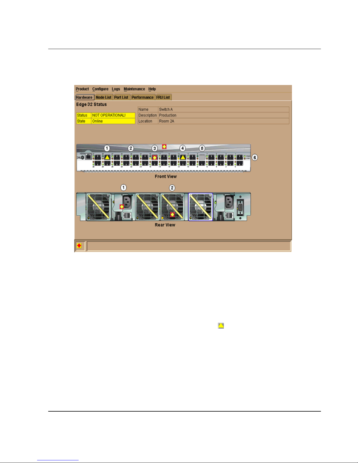
Monitoring and Managing the Switch
1 Port Attention Indicator
2 Port LED Indicator
3 Port Failure Indicator
4 Beaconing or Diagnostic Test
5 Not Installed
6 Power, System Error, and Unit
Beaconing Indicators
Figure 2–1: Monitoring Hardware Operation - Edge Switch 2/16 (Hardware View)
Front View
1. Port Attention Indicator: The yellow triangle ( ) indicates that a link incident
occurred or that the port is not operational, in nonstandard mode of operation, or
has other status. For a link incident, the status table at the top of the Hardware
View changes to reflect the reason for the alert. You can also note the reason by
displaying the Port Properties dialog box for the port. For details on status
symbols, refer to Table 2–1 on page 2-38. For information on link incidents, refer
to Link Incident Alerts on page 2-40.
edge switch 2/16 product manager user guide 2–5
Page 56

Monitoring and Managing the Switch
2. Port LED Indicator: A green and amber indicator to the left of each port
connector simulates LED operation on the actual switch port. When the green
indicator illuminates, the port is online and operational. When the amber indicator
illuminates steady, the port has failed. For details on port LED indicator operation,
see Table 2–1 on page 2-38.
3. Port Failure Indicator: A blinking red and yellow diamond ( ) below a port
connector indicates that the port has failed. Refer to Table 2–1 on page 2-38 for
details on port operating states and the status symbol and indicator operation.
4. Beaconing or Diagnostic Test: When a blinking amber LED indicator displays by
a port and an attention indicator ( ) displays below the port's connector, either
diagnostic tests are running on the port or beaconing is enabled. Refer to
Table 2–1 on page 2-38 for details on port operating states and the status symbol
and indicator operation.
5. Not Installed. The port optics are not installed, or the feature that provides
additional port function is not enabled.
6. Power, System Error, and Unit Beaconing Indicators: The green and amber
indicators on the far right of the front view simulates the power and system error
LEDs on the actual switch.
• Power Indicator. The green indicator (PWR) simulates the power LED on the
actual switch. When the indicator illuminates, the switch is connected to
facility AC power and is operational. The indicator will be on if either power
supply is operating.
• System Error Indicator. The amber system error light indicator (ERR)
simulates the system error light on the actual switch. When this indicator
illuminates, an event has occurred requiring immediate attention, such as a
system, fan, power supply, or port failure. View details of system errors by
selecting Event Log from the Logs menu on the Product Manager menu bar.
The indicator in the Hardware View and the LED on the actual unit remains
illuminated until you clear the event by right-clicking on the front or rear view
away from a hardware component and selecting Clear System Error Light
from the menu.
• Unit Beaconing Indicator. The amber indicator blinks if unit beaconing is
enabled. Enable and disable unit beaconing by right-clicking on the front or
rear view away from a hardware component and selecting Enable Unit
Beaconing from the menu.
2–6 edge switch 2/16 product manager user guide
Page 57

Rear View
1. Power Supply Status: Each AC power connector indicates the location of an
2. Fan Status: Three dual-fan modules (six fans total) are installed in the edge switch
Monitoring and Managing the Switch
internal power supply. A simulated green LED indicator is located in the upper
left corner of each AC power connector. The indicator illuminates if the power
supply is working and receiving AC power.
When a red and yellow diamond ( ) displays on a power connector, like in
Figure 2–1 on page 2-5, the internal power supply for that connector failed. In this
case, the green indicator to the top left of the connector will not illuminate. When
the green indicator is on and no status symbol displays, the power supply is
operational. Note that the switch operates with one power supply failure, however
replace the power supply as soon as possible to retain redundancy.
2/16. One module cools one power supply, one module cools the other power
supply, and one module cools the CTP card.
When the LED indicator on a fan module illuminates, as shown in the previous
illustration, and a red diamond ( ) appears over a module, the fan has failed or is
rotating insufficiently. Note that the switch continues to operate with one fan
failure. If two or more fans fail, replace them as soon as possible to avoid switch
damage.
Obtaining Hardware Information
This section explains how to access the FRU Properties, Port Properties, and switch
Properties dialog boxes.
Displaying FRU Information
Double-click a fan or power supply (AC connector) in the Hardware View to display
the FRU Properties dialog box. This dialog box displays the FRU name; slot position
relative to identical FRUs installed in the chassis, active or failed state, part number,
and serial number.
edge switch 2/16 product manager user guide 2–7
Page 58
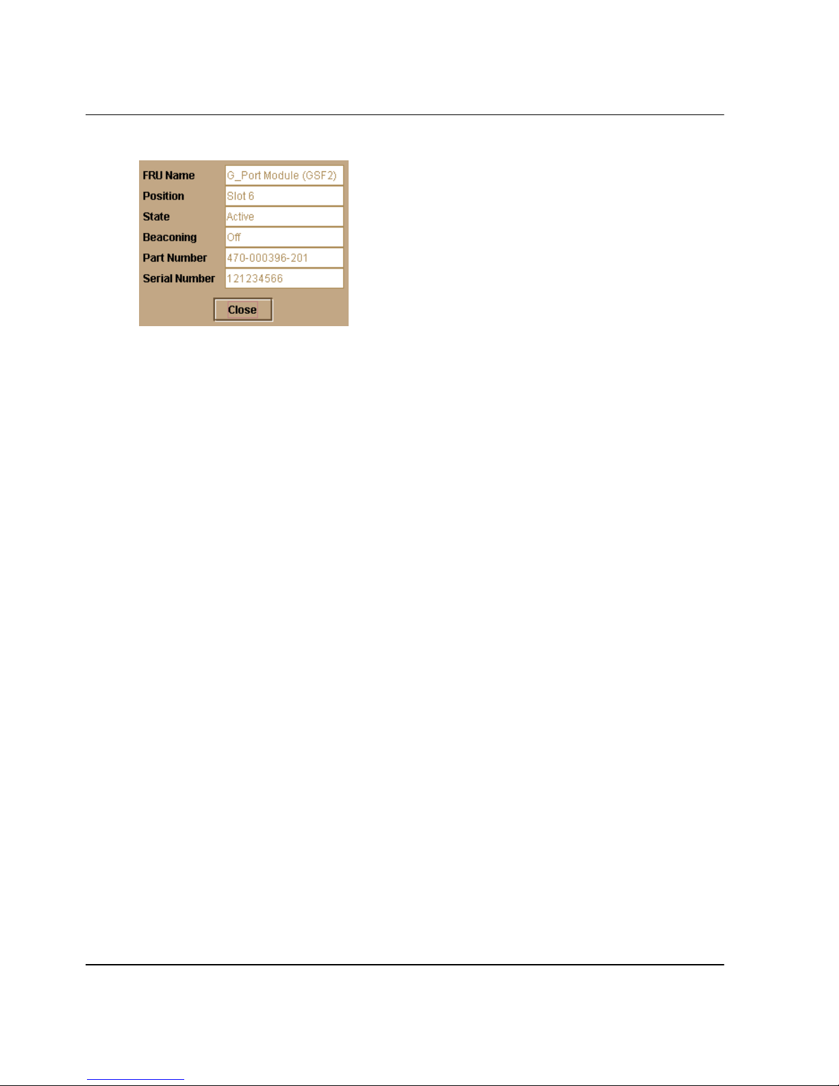
Monitoring and Managing the Switch
Figure 2–2: FRU Properties dialog box
Displaying Port Information
Double-click a port or right-click a port and select Port Properties from the menu to
display the Port Properties dialog box. Also display this dialog box by:
• Double-clicking a row in the Port List View or right-clicking on a row and
selecting Port Properties from the menu.
• Double-clicking a port’s bar graph in the Performance View or right-clicking on
the bar graph and selecting Port Properties from the menu.
• Right-clicking a port’s row in the Node List View and selecting Port Properties
from the menu.
• Click in a port, port row, or port bar graph in the preceding views and selecting the
Port secondary menu from the Product menu on the menu bar.
2–8 edge switch 2/16 product manager user guide
Page 59
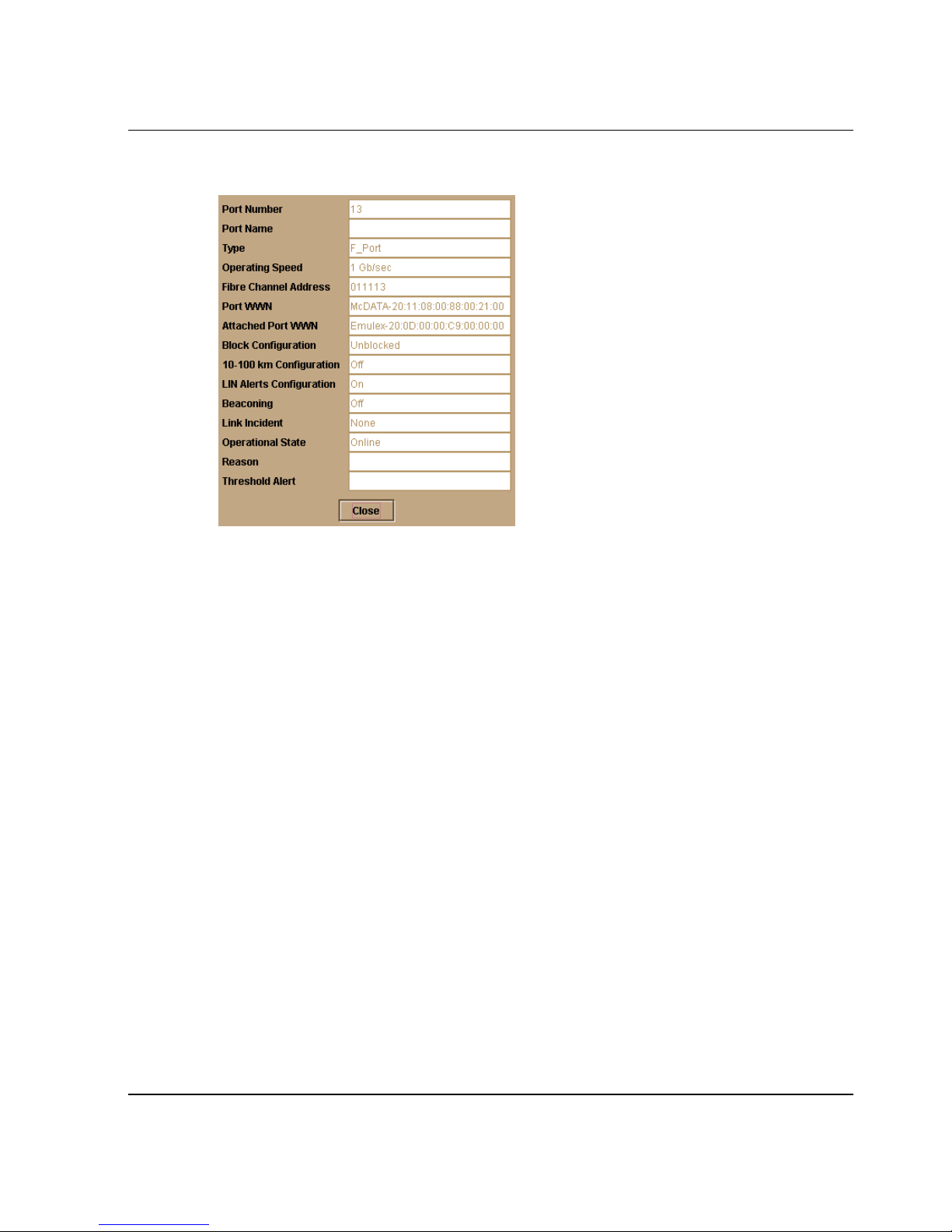
Figure 2–3: Port Properties dialog box
Monitoring and Managing the Switch
The following paragraphs describe the fields in the Port Properties dialog box:
•Port Number
The physical port number.
•Port Name
User-defined port name or description. Refer to Configure Ports on page 3-8 for
instructions.
•Type
— G_port. This displays if nothing is logged into the port.
— F_Port. This displays if a device is logged into the port.
— E_Port. This displays if the port is connected to another switch’s E_Port via
an ISL.
• Operating Speed
This field displays the current data speed for the port as 1 Gb/sec, 2 Gb/sec, or Not
Established. “Not Established” displays if Negotiate was set for the port through
the Configure Ports dialog box and the data speed has not been resolved between
the port and the attached device, or if the port and device are not communicating.
edge switch 2/16 product manager user guide 2–9
Page 60

Monitoring and Managing the Switch
• Fibre Channel Address
The port’s Fibre Channel address identifier.
• Port WWN
The port’s 16-digit world-wide name (WWN).
• Attached Port WWN
The WWN of the node logged into the port.
• Block Configuration
Blocked or unblocked. Operation can be blocked or unblocked through the
Configure Ports dialog box. Refer to Configure Ports on page 3-8 for instructions.
• 10-100 km Configuration
Extended distance buffering. This can be enabled or disabled for the port through
the Configure Ports dialog box. Refer to Configure Ports on page 3-8 for
instructions.
• LIN Alerts Configuration
This field indicates whether LIN alerts are enabled or disabled. LIN alerts can be
configured through the Configure Ports dialog box. The default is for the LIN
alerts to be enabled.
• Beaconing
This field indicates the beaconing status for the port. To enable or disable
beaconing, right-click the port and select Enable Beaconing.
• Link Incident
Description of the last link incident that occurred on the port.
• Operational State
Beaconing, inactive, invalid attachment, link incident, link reset, no light, not
operational, online, offline, port failure, segmented E_Port, testing, or not
installed. Refer to Table 2–1 on page 2-38 for definitions of operational states.
•Reason
When the port operating state is “Segmented E_Port,” “Invalid Attachment,” or
“Inactive,” this field displays the reason for that state. When an E_Port is
segmented, two fabrics are prevented from joining. This only occurs when the
switch is connected to another switch. Reasons and probable causes are listed
under Reason Field Messages (following).
2–10 edge switch 2/16 product manager user guide
Page 61

Monitoring and Managing the Switch
• Threshold Alert
If a threshold alert exists for the port, an alert indicator (yellow triangle) will
appear by the Threshold Alert field, and the configured name for the last alert
received will appear in the field.
Reason Field Messages
The following messages display in the Reason field of the Port Properties dialog box
if an Invalid Attachment, Segmented E_Port, or Inactive state occurs for the port.
Invalid Attachment Messages:
• 01 Unknown. Invalid attachment reason cannot be determined.
• 02 ISL connection not allowed on this port. Port is configured as an F_Port, but
connected to switch.
• 03 ELP rejected by the attached switch. This switch transmitted an exchange link
protocol (ELP) frame that was rejected by the switch at the other end of the ISL.
• 04 Incompatible switch at the other end of the ISL. Interop mode for this switch is
set to Open Fabric mode and the switch at the other end of the ISL is a HP switch
configured for homogeneous fabric mode.
• 05 External loopback adapter connected to the port. A loopback plug is
connected to the port and there is no diagnostic test running.
• 06 N_Port connection not allowed on this port. The port type configuration does
not match the actual port use. Port is configured as an E_Port, but attaches to a
node device.
• 07 Non-HP switch at other end of the ISL. The cable is connected to a non-HP
switch and interop mode is set to homogeneous fabric mode.
• 08 ISL connection not allowed on this port. The port type configuration does not
match the actual port use (the port is configured as an F_Port, but attaches to a
switch or director).
• 10 Port binding violation - unauthorized WWN. The WWN entered to configure
port binding is not valid or a nickname was used that is not configured through the
Product Manager for the attached device.
• 11 Unresponsive node connected to port. Possible causes are:
— Hardware problem on switch or on a connected node where ELP frames are
not delivered, the response is not received, or a fabric login in (FLOGI)
cannot be received. There may be problems in switch SBAR.
edge switch 2/16 product manager user guide 2–11
Page 62

Monitoring and Managing the Switch
— Faulty or dirty cable connection.
— Faulty host bus adapters that do not send out FLOGI within reasonable time
frame.
Segmented E_Port Messages:
• Incompatible operating parameters, such as resource allocation time-out values
(R_A_TOV) or error-detect time-out values (E_D_TOV) are inconsistent. Refer
to Configure Operating Parameters on page 3-4 for more information.
• Duplicate domain IDs. Refer to Configure Operating Parameters on page 3-4 for
more information.
• Incompatible zoning configurations. Refer to sections on joining zoned fabrics in
the hp StorageWorks edge switch 2/16 service manual
(A7284-96002/AA-RS2JA-TE) and the hp StorageWorks ha-fabric manager user
guide (A6534-96024/AA-RS2CA-TE) for details.
• Build fabric protocol error.
• No principal switch (no switch in fabric is capable of being principal switch).
• No response from an attached switch.
Inactive Messages:
Optics speed conflict. An inactive state will occur if you set the port’s data speed to 2
Gb/sec for a 2 Gb/sec port module, and then replace the port module with a 1 Gb/sec
module. To activate the port in this case, replace the module with a module that
supports 2 Gb/sec data speed.
Displaying Switch Information
Double-click the switch illustration, away from a hardware component, to display the
Switch Properties dialog box as shown in the following figure.
2–12 edge switch 2/16 product manager user guide
Page 63
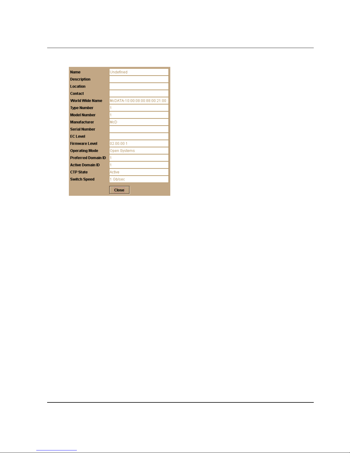
Figure 2–4: Switch Properties dialog box
Monitoring and Managing the Switch
The following displays in this dialog box:
• Switch Name, Description, Location, and Contact configured through the
Configure Identification dialog box.
• Fibre Channel World Wide Name (WWN) identifier for the switch.
• Product Type Number.
•Product Model Number.
• Product Manufacturer.
• Product Serial Number.
• Engineering change level (EC Level).
• Firmware Level.
• Operating Mode as set through the Configure Operating Mode dialog box.
• Preferred Domain ID as set through the Configure Operating Parameters dialog
box.
• Active Domain ID. The actual domain ID assigned to the switch.
• Switch Speed. This is always set to 2 Gb/sec.
edge switch 2/16 product manager user guide 2–13
Page 64

Monitoring and Managing the Switch
Using Menu Options
Right-click on various parts of the Hardware View to display menu options for
displaying status and information and for controlling the switch and various hardware
components.
Switch Menu
Right-click on any area of the switch illustration where a FRU hardware component is
not installed to display the following menu options.
Switch Properties
Click to display the Switch Properties dialog box. This dialog box contains the switch
name, description, location, and contact person configured through the Configure
Identification dialog box. Also included is other product information as detailed in
Displaying Switch Information on page 2-12. You can also display this dialog box by
double-clicking an area on the illustration away from a hardware component.
Enable Unit Beaconing
Click the check box to toggle unit beaconing on or off. When the check box has a
check mark, unit beaconing is on, and the system error light (ERR) on the switch
blinks to help users locate the unit managed by the Product Manager. The amber
indicator on the Hardware View also blinks when beaconing is enabled. When you
click the check box to remove the check mark, the unit beaconing is disabled.
NOTE: You can only enable beaconing if there are no system errors (the system error light is
off).
Clear System Error Light
Select this to turn off the amber system error light (ERR), located below the green
power (PWR) LED on the switch. This also turns off the amber system error light
indicator in the Hardware View (front view)
IPL Switch
Select this option to initiate an IPL on the switch. When the dialog box displays
confirming the IPL, click Yes .
NOTE: An IPL is not intended for ordinary or casual use and should only be performed when
directed by your support personnel.
Refer to Execute an IPL on page 5-2 for detailed procedures.
2–14 edge switch 2/16 product manager user guide
Page 65
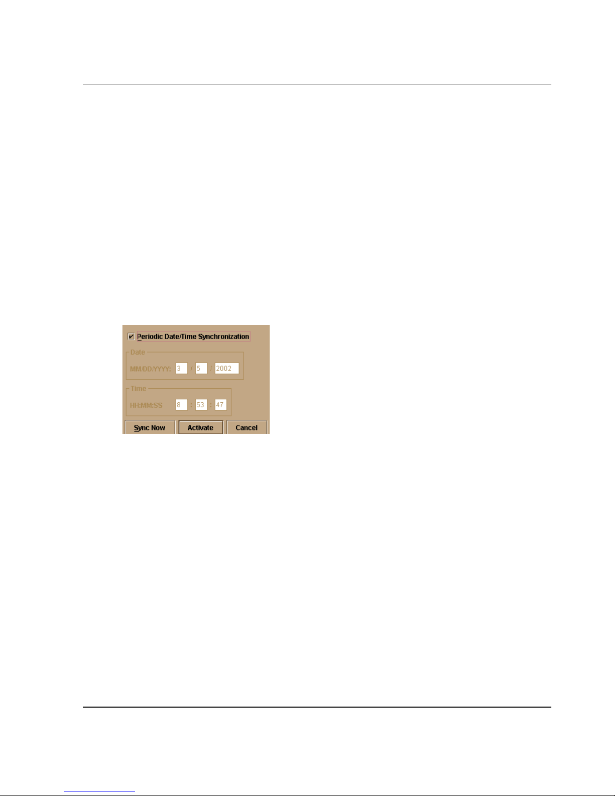
Monitoring and Managing the Switch
Set Switch Date and Time
Select this option to display the Configure Date and Time dialog box.
1. Click to display the Configure Date and Time dialog box.
The dialog box displays with a check mark (the default) in the Periodic Date/Time
Synchronization check box. If this field is checked, the HAFM server periodically
sets the switch time to automatically synchronize with the HAFM server time.
Daylight savings time automatically updates on the switch using this option.
The current date and time display in the Date and Time fields. If the Periodic
Date/Time Synchronization field is checked, the Date and Time fields are disabled
(grayed out).
To enable and disable Periodic Date/Time Synchronization, click the check box
and then click Activate.
Figure 2–5: Configure Date and Time Periodic Synchronization dialog box
2. Perform one of the following steps:
• To immediately synchronize the switch date and time with the HAFM server, be
sure the Periodic Date/Time Synchronization option is enabled and then click Sync
Now.
NOTE: If you enable the Periodic Date/Time Synchronization feature and click Activate, the
time will synchronize at the next update period.
To set the switch with a specific date and time, make sure that the Periodic
Date/Time Synchronization field is not selected. Refer to Figure 2–6. Enter the
date and time and then click Activate.
S/390 mode only. An error will result if periodic synchronization and switch clock
alert mode are enabled (refer to Configure FICON Management Server on
page 3-21)
edge switch 2/16 product manager user guide 2–15
Page 66
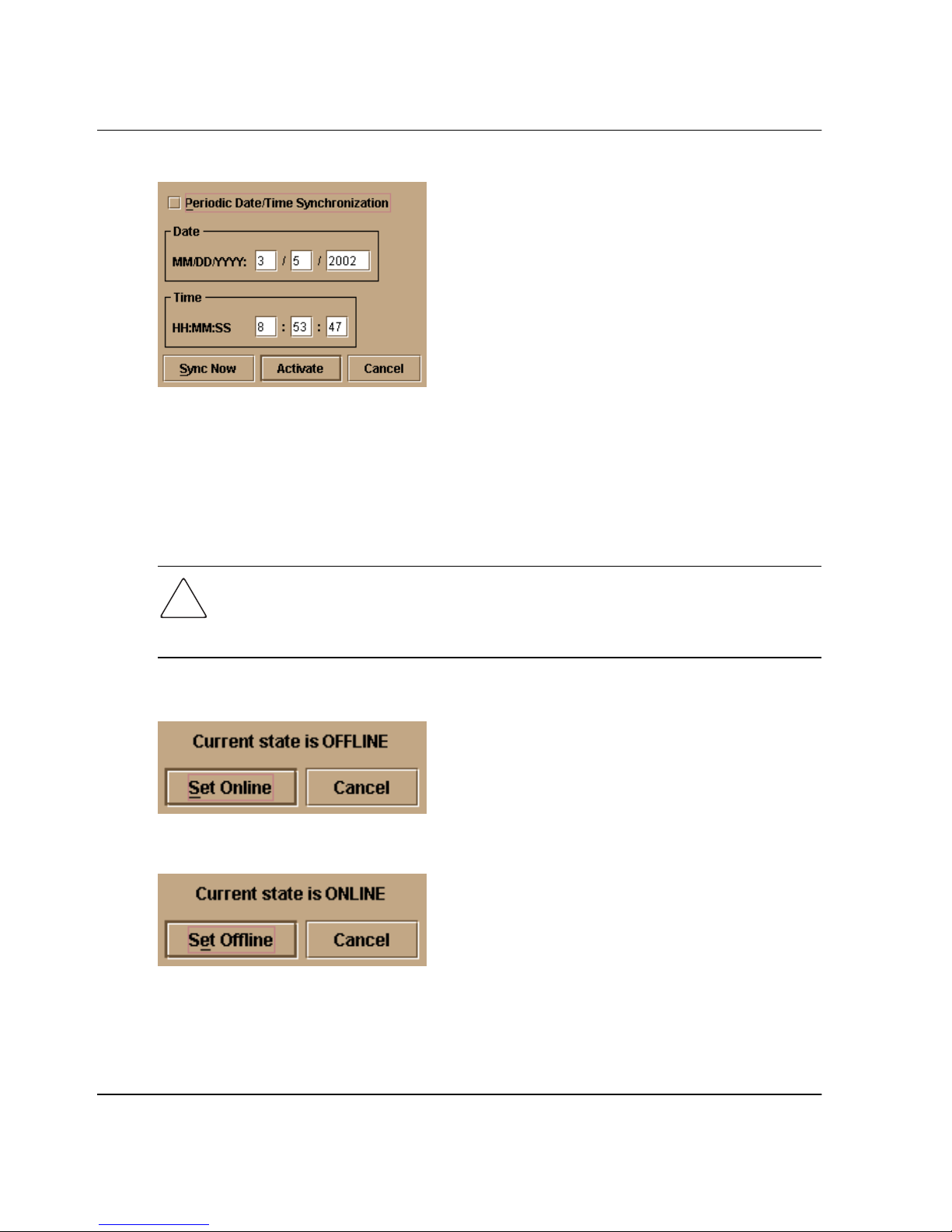
Monitoring and Managing the Switch
Figure 2–6: Configure date and time manually
NOTE: Use the range of 0 to 23 for hours. Use the range of 0 to 59 for minutes and seconds.
Set Switch Online State
Click to display the Set Online State dialog box. The dialog box displays the current
state (offline or online) and provides a button for changing the state.
CAUTION: Before setting the switch offline, warn administrators and users currently
operating attached devices that the switch is going offline and that there will be a
disruption of port operation. Also, request that the devices affected by an interruption
of data flow be set offline.
1. Click the Set Offline or Set Online button to toggle between the states.
Figure 2–7: Set Online State dialog box (Offline)
Figure 2–8: Set Online State dialog box (Online)
2. When the Set Online or Set Offline warning dialog box displays, click OK to set
the switch online or offline.
2–16 edge switch 2/16 product manager user guide
Page 67

Port Menu
While in the Hardware View, right-click on any port to display the following menu
options.
Port Properties
Click this to display the Port Properties dialog box. This dialog box displays technical
information about the port. See Displaying Port Information on page 2-8 for more
information.
Node Properties
Click this to display the Node Properties dialog box. Note that if a node is not logged
into the port, a message appears indicating that node information is not available. For
details on information that displays in this dialog box, refer to Displaying Node
Properties on page 2-29.
Monitoring and Managing the Switch
As the switch goes offline, the word, “OFFLINE,” displays in the State field in the
left corner of the Hardware View. As the switch goes online, the word,
“ONLINE,” displays in the State field in the left corner of the Hardware View.
When going offline, LED indicators on all ports with attached devices stay green,
but the switch sends offline sequences (OLS) to these devices.
Port Technology
Click this to display the Port Technology dialog box. This dialog box displays the
following information:
• Port number.
• Connector type: Always LC.
• Transceiver type: Longwave laser LC or shortwave laser LC.
• Distance: General distance range for port transmission. This can be either short to
long distances for the longwave laser LC transceiver or short distances for the
shortwave laser LC transceivers.
• Media: The Fibre Channel mode and optic size. For the longwave laser LC
transceiver, this would be singlemode 9-micron. For the shortwave laser LC
transceiver, this would be multimode 50-micron or 62.5-micron.
• Speed: This will be either 1 Gbit per second or 1 Gbit, 2 Gbit per second.
edge switch 2/16 product manager user guide 2–17
Page 68

Monitoring and Managing the Switch
Block Port
Click to display a check mark and block port transmission If blocked, a node attached
to the port is prevented from logging into the switch or communicating with other
devices attached to switch ports. A blocked port continuously transmits offline signals
(OLS). Click to remove the check mark and unblock the port. If unblocked, a node
attached to the port can communicate with the switch and communicate with other
nodes attached to the switch.
Enable Beaconing
Click this to make the amber LED by the port blink on the actual switch and the amber
indicator blink for the port in the Hardware View. This enables users to locate the unit
where the port is located. When a blinking amber LED indicator displays by a port, an
attention indicator ( ) displays below the port's connector in the Hardware View and
on the port’s row in the Port List View.
Port Diagnostics
Click this option to display the Port Diagnostics dialog box. Use this dialog box to run
an internal loopback and external loopback test on the port. The Port Diagnostics
option enables you to run internal and external loopback tests on any port. To use this
option, follow the detailed steps in the hp StorageWorks edge switch 2/16 service
manual (A7284-96002/AA-RS2JA-TE).
Channel Wrap (S/390 mode only)
Click this while in S/390 mode to display a check mark and allow a channel wrap test
to be initiated from an attached host or device. In this test, frames are sent to the
switch port, then the switch echoes the frames back to the sending device to test the
channel. The switch remains in channel wrap mode until the option is disables. While
in channel wrap mode, the port can only accept echo commands from the host and will
appear to be blocked to all other communication. Click the check box to remove the
check mark and disable channel wrap.
Swap Ports (S/390 mode only)
Click this while in S/390 mode to display the Swap Ports dialog box. Use this dialog
box to swap addresses between ports. For details, refer to Swap Ports on page 5-1.
2–18 edge switch 2/16 product manager user guide
Page 69
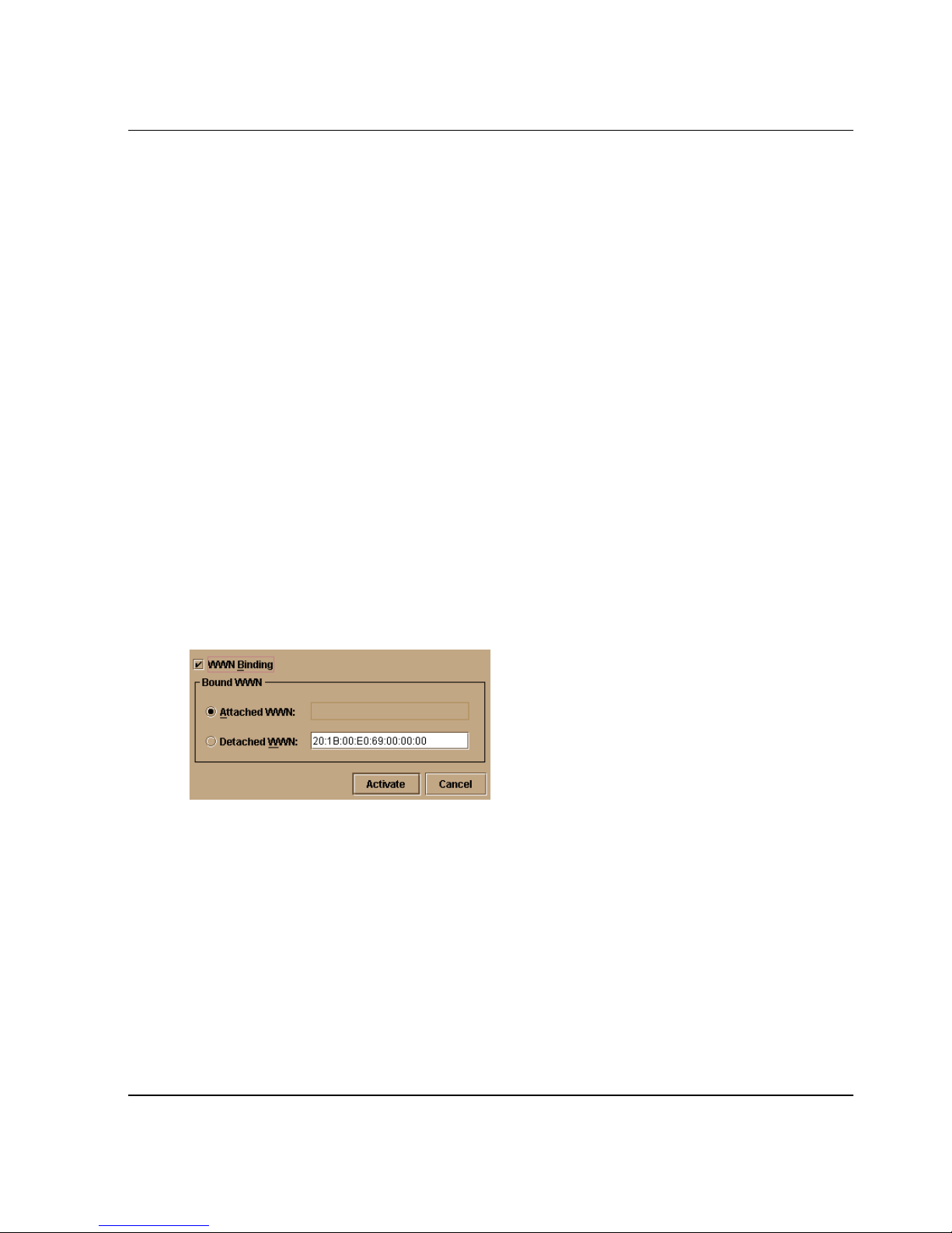
Monitoring and Managing the Switch
Clear Link Incident Alert(s)
Click this to clear the attention indicator on the Hardware View, the Port List View,
and the Performance View. In addition, the procedure clears the alert description in
Port Properties dialog boxes. If there are no link incident alerts set for a port, no
actions occur. Although you can manually clear link incidents, they may also be
cleared by actions outside of the user interface, such as when rebooting the HAFM
server.
Reset Port
Click to display a confirmation dialog box. Click Yes on that dialog box to reset the
port. If a switch is attached to the port and online, this operation sends a link reset to
the attached switch, otherwise this action disables port beaconing for the port. If the
port is in a failed state, such as after failing a loopback test, the reset restores the port
to an operational state, clearing the service required (amber) LED. The reset does not
affect other ports in the switch.
Port Binding
Click to display the Bind WWN dialog box (Figure 2–9). Use this dialog box to allow a
device with a specific WWN or nickname to have exclusive connection to a port. To
use this dialog box, refer to the following paragraphs.
Figure 2–9: Bind WWN dialog box
Bind WWN dialog box parameters:
• Port Binding: Click this check box to place check mark in the box and enable
WWN binding for the port. When enabled, only a specific device can
communicate through the port. This device is specified by the WWN or nickname
entered into the Bound WWN field (either the Attached WWN or WWN options).
With the check box cleared, any device can communicate through the port even if
a WWN or nickname is specified in the Bound WWN field.
edge switch 2/16 product manager user guide 2–19
Page 70

Monitoring and Managing the Switch
• Attached WWN: Click the radio button and, if a device is logged into the port,
the device's WWN will display in the field. The device with this WWN or
nickname will have exclusive communication privileges to the port if Port
Binding is enabled.
NOTE: If you click this radio button to bind the port to a logged-in device and there are no
devices logged in, the port is essentially bound to a WWN of “0.” This prevents any device from
logging in until this button is re-enabled to bind the WWN of a logged-in device or until you
explicitly bind the WWN of a device by clicking the detached WWN radio button and entering a
WWN or nickname (see the following). Changes only take effect when you click the Activate
button.
• Detached WWN: Click the radio button and enter a world wide name (WWN) in
the proper format (xx.xx.xx.xx.xx.xx.xx.xx) or a nickname configured through
the Product or HAFM applications. The device with this WWN or nickname will
have exclusive communication privileges through the port if Port Binding is
enabled.
Note the following:
— If you do not enter valid WWN or nickname in this field, but the Port Binding
check box is checked (enabled), then no devices can communicate over the
port.
— If you enter a WWN or nickname in this field and do not place a check in the
Port Binding checkbox, the WWN or nickname will be stored, and all devices
can communicate over the port.
• Activate: Click this button to activate settings in this dialog box.
Warning and error message display:
• If one or more of the nodes logged into a port does not match the WWN or
nickname configured in the field by the WWN radio button, a warning dialog box
displays after you activate the configuration. This warning box displays a list of
all nodes that will be logged off if you continue. If you click Continue on the
warning box, these nodes will be logged off and the port will only attach to the
device with the device with the WWN or nickname configured in the WWN field.
• An error message displays after you activate the configuration if the format for the
WWN entered in the WWN field is not valid (not in xx.xx.xx.xx.xx.xx.xx.xx
format) or if you have entered a nickname that was not configured through the
Product Manager.
2–20 edge switch 2/16 product manager user guide
Page 71
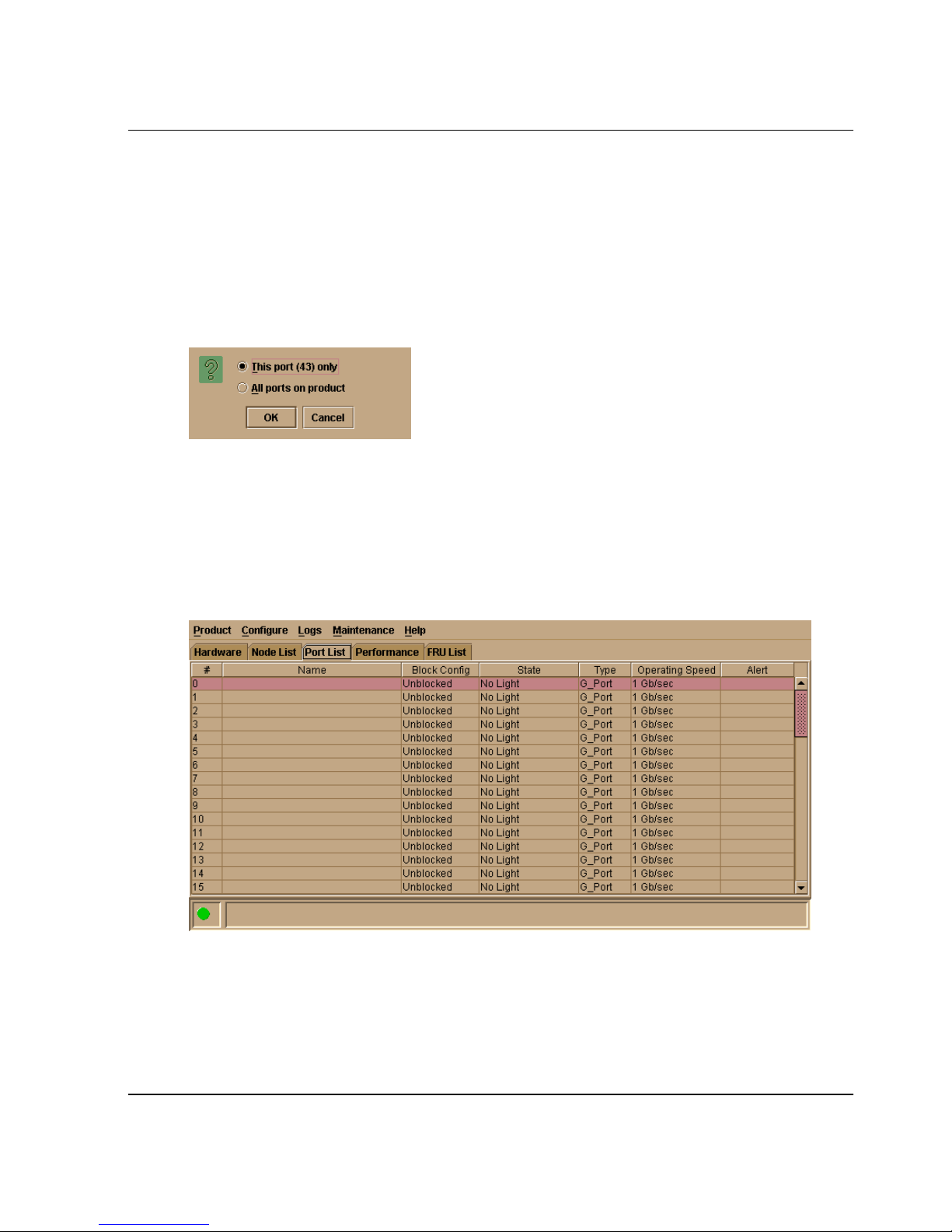
Clear Threshold Alert(s)
Click this to display the Clear Threshold Alert(s) dialog box. Select the appropriate
option to clear alerts for the selected port only or all ports on the switch. This clears all
attention indicators that notify users of threshold alerts in dialog boxes and views.
This action also restarts the notification interval and the cumulative minutes for
utilization % interval.
Figure 2–10: Clear Threshold Alert(s) dialog box
Port List View
Monitoring and Managing the Switch
Display the Port List View (Figure 2–11) in the view panel by selecting the Port List
option from view tabs on the Product Manager window.
Figure 2–11: Port List View
The Port List View displays the following information on all ports that can be installed
in the switch. All information is updated automatically.
edge switch 2/16 product manager user guide 2–21
Page 72

Monitoring and Managing the Switch
•#
Number of the port from 0 through 15.
• Addr (S/390 mode)
Displays the logical address of the port. The address equals the port number, plus
4. For example, the address for port 0 is 4 (0+4). If port addresses have been
swapped, those addresses will be followed by an asterisk (*).
•Name
Displays the port name as configured through the Configure Ports dialog box.
• Block Config
Indicates the blocked or unblocked configuration of the port as set through:
—The Configure Ports dialog box.
—The Configure Addresses - “Active” dialog box. (S/390 mode only).
The Block Port option available through port right-click menus in the Hardware
View, port row right-click menus in the Port List view, is also the port bar graph
right-click menus in the Performance View, and the Port secondary menu of the
Product menu on the menu bar.
Blocked states are:
— Blocked: Devices communicating with the port are prevented from logging
into the switch or communicating with other devices attached to switch ports.
A blocked port continuously transmits OLS.
— Unblocked: Devices communicating with the port can log in to the switch
and communicate with devices attached to any other unblocked port in the
same zone.
• State
The following port operational states may display in this table. For more
information on these states and corresponding status symbol and LED indicator
operations in the Hardware View, see Port Operational States on page 2-38.
— No Light
—Online
— Offline
— Beaconing
—Link Reset
2–22 edge switch 2/16 product manager user guide
Page 73

Monitoring and Managing the Switch
— Not Operational
— Not Installed
— Invalid Attachment
— Port Failure
— Segmented E_Port
— Link Incident
— Testing
— Inactive
•Type
The type of port.
— It is an F_Port if an N_Port is attached.
— It is an E_Port if another E_Port is attached.
— It is a G_Port if the port is capable of acting as either an F_Port or an E_Port,
but nothing is currently attached.
• Operating Speed
This field displays the current data speed for the port as 1 Gb/sec, 2 Gb/sec, or Not
Established.
•Alert
This column displays a yellow triangle if a link incident occurs on the port or if
the port's LED is beaconing. Blinking red and yellow diamonds display for port
failures or for ports requiring service. Click on the row to display the reason for
the alert in the Port Properties dialog box.
Double-click a row to display the Port Properties dialog box. For an explanation of
the fields on the Port Properties dialog box, refer to Displaying Port Information on
page 2-8.
Menu Options
Right-click a row to select it, highlight it, and display a menu with the following
port-related action options. These are the same menu options that display when you
right-click a port in the Hardware View and Performance View. You can also display
this menu by clicking on a port, port row, or port graph in the preceding views and
selecting the Port secondary menu from the Product menu on the menu bar.
edge switch 2/16 product manager user guide 2–23
Page 74

Monitoring and Managing the Switch
Refer to Port Menu on page 2-17 for an explanation of these menu options.
• Port Properties
• Node Properties
• Port Technology
• Block Port
• Enable Beaconing
• Port Diagnostics
• Channel Wrap (S/390 mode only)
• Swap Ports (S/390 mode only)
• Clear Link Incident Alert
•Reset Port
• Port Binding
• Clear Threshold Alert(s)
NOTE: For Node Properties, if a node is not logged in a message displays indicating that node
information is not available.
FRU List View
Display the FRU List in the main panel by selecting the FRU List view tab on the
Product Manager window. This view displays information about all installed FRUs on
the switch. All data is dynamic and updates automatically as the software detects
changes.
2–24 edge switch 2/16 product manager user guide
Page 75
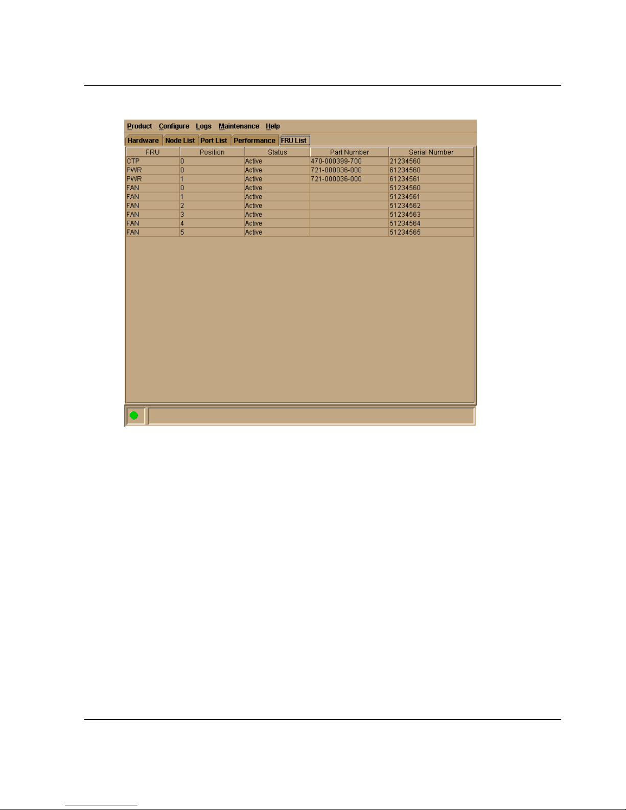
Monitoring and Managing the Switch
Figure 2–12: FRU List View
Information on the FRU List View for each FRU includes:
• FRU Name: CTP (Control Processor), FAN (fan module), and PWR
(power-supply module). Note that the CTP is an internal component, and if it fails
completely the entire switch must be replaced.
• Position: Slot position of FRU in the chassis relative to identical FRUs also
installed in the chassis. In the edge switch 2/16, there are three dual-fan modules
(positions 0-2), one CTP card (position 0), two power supplies (positions 0-1),
and 16 port positions (0-15).
• Status: Active or failed. Active displays always unless the FRU fails. Failed
displays if the FRU is not functional.
• Part Number: Part number of the FRU.
• Serial Number: Serial number of the FRU.
edge switch 2/16 product manager user guide 2–25
Page 76
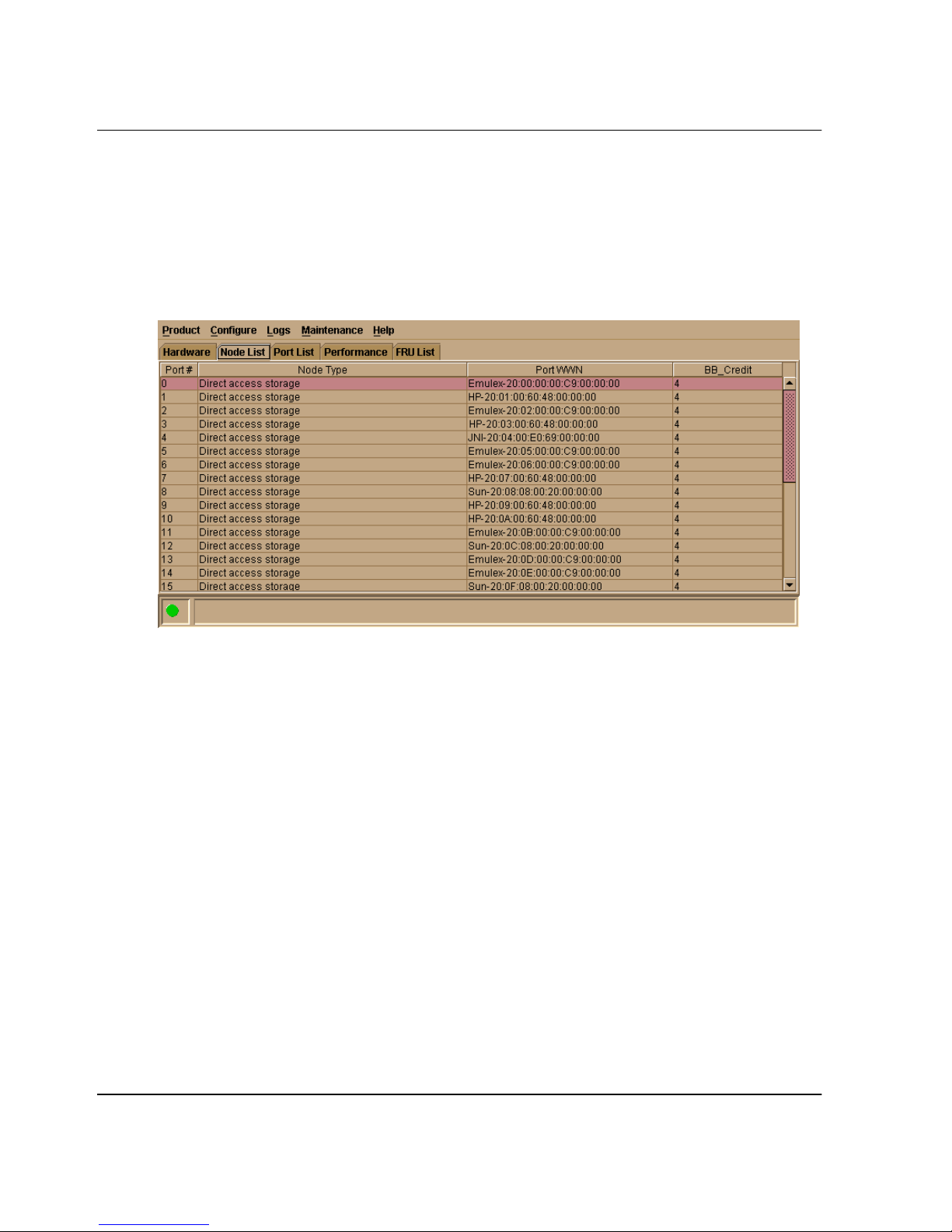
Monitoring and Managing the Switch
Node List View
Display the Node List View in the view panel by selecting Node List from the view
tabs on the Product Manager window. This view displays information about all node
attachments to any F_Ports on the switch sorted by port number. All data is dynamic
and updates automatically as devices log in and log out.
Figure 2–13: Node List View
Information that displays for each node includes:
•Port #
Number of the port, from 0 through 15.
• Addr (S/390 mode only)
Displays the logical port address.
•Node Type
The following information, if supported, is supplied by the attached device:
— Unknown
—Other
—Hub
— Switch
2–26 edge switch 2/16 product manager user guide
Page 77

— Gateway
— Converter
—HBA
— Proxy-agent
— Storage device
—Host
— Storage subsystem
— Module
— Software driver
— Unspecified
— Direct access storage
— Magnetic tape
— Unit record (input)
Monitoring and Managing the Switch
— Unit record (output)
—Printer
— Communications controller
— Terminal (full screen)
— Terminal (line mode)
— Stand-alone CTC adapter
— Switch
— Channel path ##
where ## will be replaced with the Channel Path Identifier (2 hex digits)
— Integrated CTC adapter
— Reserved
• Port WWN
The port WWN of the attached node (N_Port). The 16-digit WWN is a set of
unique numbers assigned to the device attached to the port. The WWN is prefixed
by the manufacturer’s name of the host bus adapter that attaches to the device. If
there is a nickname assigned, the nickname displays instead of the WWN.
edge switch 2/16 product manager user guide 2–27
Page 78

Monitoring and Managing the Switch
• BB_Credit
The buffer-to-buffer credit that the attached node has available.
Double-click a row to display the Node Properties dialog box. For an explanation of
the fields on the Node Properties dialog box, refer to Displaying Node Properties on
page 2-29.
Menu Options
Right-click a row to select it, highlight it, and display a menu with the following
port-related action options:
• Node Properties
Select this option to display the Node Properties dialog box. Refer to Displaying
Node Properties on page 2-29 for details.
•Port Properties
Select this option to display the Port Properties dialog box (refer to Figure 2–3 on
page 2-9).
• Define Nickname
Select this option to display the Define Nickname dialog box, where you can
define a nickname to display for the attached device instead of the device's 8-byte
WWN.
The Define Nickname dialog box displays the world wide name (WWN) of the
device attached to the port. To define a nickname, enter a name of up to 32
characters in the Nickname field and click OK. The nickname will display under
the Port WWN column instead of the device's WWN.
• Display Options
Select Nickname or Worldwid e Name from the submenu. Selecting Nickname
displays attached devices in the Port WWN column by the nickname configured
through the Define Nickname menu option. Selecting Worldwide Na me displays
attached devices in the Port WWN column by the device's WWN.
Note that you can also display these menu options by clicking a port row, and
selecting the Port secondary menu from the Product menu on the Product
Manager menu bar.
2–28 edge switch 2/16 product manager user guide
Page 79
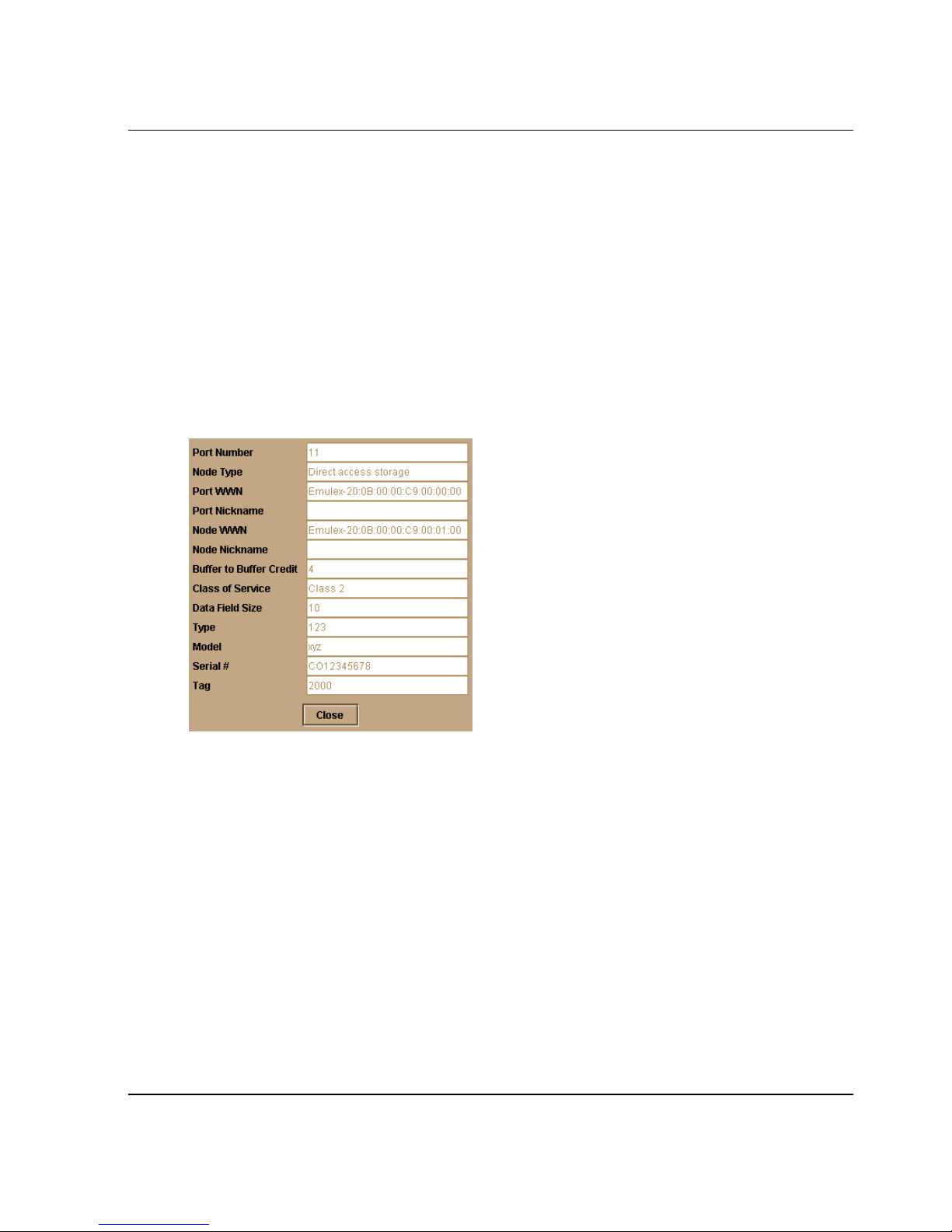
Displaying Node Properties
Open the Node Properties dialog box by double-clicking a row in the Node List View
or right-clicking a row and selecting Node Properties from the menu. You can also
display this dialog box by right-clicking on a port in the Hardware View, right-clicking
on a port’s row in the Port List View, or right-clicking on a port’s bar graph in the
Performance View and selecting Node List from the menu. In addition, you can display
this dialog box by clicking to select a port, port row, or port bar graph in the preceding
views and selecting Node Properties from the Port secondary menu on the Product
menu of the Product Manager menu bar.
NOTE: If a node is not logged in, a message appears indicating that node information is not
available.
Monitoring and Managing the Switch
Figure 2–14: Node Properties dialog box
•Port Number
The physical port number on the Switch to which the node is connected.
• Port Address (S/390 mode only)
The logical port address.
NOTE: The field only applies during S/390 mode and does not display in open systems mode.
•Node Type
Type of node which is supplied from the attached device.
• Port WWN
Port world-wide name of the attached device.
edge switch 2/16 product manager user guide 2–29
Page 80

Monitoring and Managing the Switch
• Port Nickname
Nickname for the port WWN. Must be configured to display.
• Node WWN
Node world-wide name of the attached device.
• Node Nickname
Nickname for the node WWN. Must be configured to display.
• Node Port Number
The physical port number field of the node port that is attached to the switch port
on SB-2 nodes only.
• Buffer-to-Buffer Credit
The buffer-to-buffer credit that the attached node has available.
• Class of Service
Class of service. This can be class 2, class 3, or both.
• Data Field Size
Data field size. This is the largest size of Fibre Channel frame the node will
process. The size is negotiated with the attached device.
If the device is an SB-2 (FICON) node, the following additional fields will display:
•Type
The type number.
•Model
The model number.
• Serial #
Plant of manufacture and sequence number field.
•Tag
Tag field.
NOTE: Node Properties is also available from the menu that displays when you right-click a
port’s row in the Port List View or on a port’s bar graph in the Performance View.
2–30 edge switch 2/16 product manager user guide
Page 81
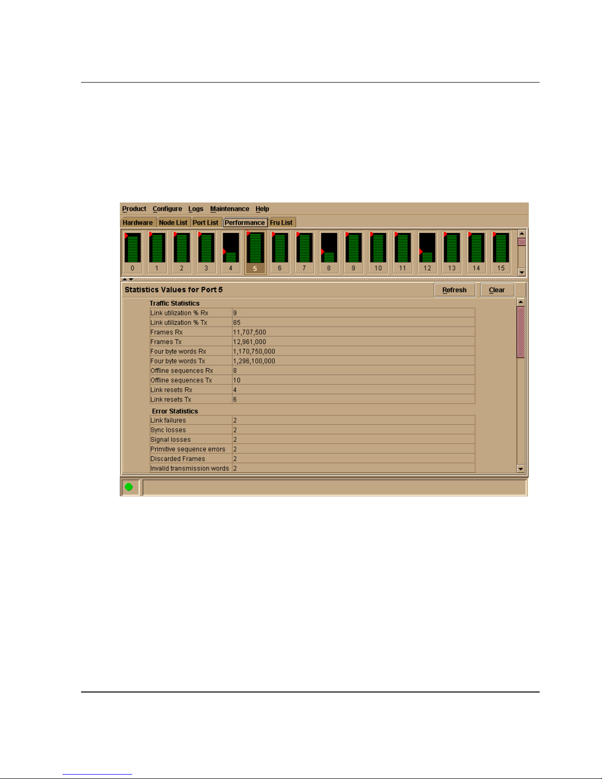
Performance View
Display the Performance View in the view panel by selecting Performance from the
view tabs in the Product Manager window. This view displays a bar graph at the top of
the view for each port. The lower portion of the view displays statistical values for the
specific port’s bar graph that you select.
Monitoring and Managing the Switch
Figure 2–15: Performance View
Menu Options
Right-click any of the port bar graphs to display a menu with the following
port-related action options. These are the same menu options that display when you
right-click a port in the Hardware View or on a row in the Port List View. You can also
display these options by clicking a port, port row, or port bar graph in the preceding
views and selecting the Port secondary menu from the Product menu on the menu bar.
Refer to Port Menu on page 2-17 for an explanation of these menu options.
• Port Properties
edge switch 2/16 product manager user guide 2–31
Page 82

Monitoring and Managing the Switch
• Node Properties
• Port Technology
• Block Port
• Enable Beaconing
• Port Diagnostics
• Channel Wrap (S/390 mode only)
• Swap Ports (S/390 mode only)
• Clear Link Incident Alert(s)
•Reset Port
• Port Binding
• Clear Threshold Alert(s)
NOTE: For node properties, If a node is not logged in, a message displays indicating that node
information is not available.
Bar Graph Display
The Performance View provides a graphical display of performance for all ports. Each
bar graph in the upper portion of the view panel displays the percentage of link
utilization for the port. This information updates every five seconds. A red arrow
marks the highest utilization since the opening of the Performance View. If the system
detects activity on a port, it represents minimal activity with one bar.
When a port is logged in, moving the cursor over its bar graph displays a message with
the attached port’s WWN. If the port is an E_Port, the message reads, “E_Port” and if
the port is not logged in, the message displays the port’s current operational state
(refer to Table 2–1 on page 2-38).
Port Statistics
To select and display more detailed performance information for a port, click the
port’s bar graph. The bar graph for that port highlights with a darker background and
the lower portion of the Performance View view panel displays the statistics values for
the port’s number and the WWN decoding. The Statistics Values tables contain
cumulative port statistics and error statistics. For a description of the Refresh and
Clear buttons, refer to Button Functions on page 2-37.
2–32 edge switch 2/16 product manager user guide
Page 83

Statistics Description
The Statistics Values tables contain statistics in the following groups. To refresh tables
with the latest data, click the Refresh button on the upper right portion of the Statistics
Va l ue s panel or click the port’s bar graph. Clear all counters for all users using the
Clear button.
Traffic Statistics with Receive and Transmit Values
This section describes the types of statistics that display when you click a port’s bar
graph:
• Link Utilization%
There is a separate value for transmit and receive link utilization. The larger of
these two values displays on the bar graph.
The current link utilization for the port is expressed as a percentage. Each port can
transmit or receive data at 200 Megabytes (MB) per second.This statistic shows
the percentage of the maximum link utilization currently being used. Link
utilization is calculated over one-second intervals. The maximum link utilization
is 100%.
Monitoring and Managing the Switch
•Frames
The number of frames that the port has received or transmitted.
• Four Byte Words
The number of words that the port has received or transmitted.
• Offline Sequences
The number of offline sequence that the port has received or transmitted.
• Link Resets
The number of link reset protocol frames received/transmitted by this port from/to
the attached switch. The switch transmits a link reset to initiate the link reset
protocol or recover from a link timeout. This occurs normally to establish
BB_Credit or on any port in order to recover lost BB_Credit. The switch receives
a link reset from an attached device if the device wishes to initiate the link reset or
recover from a link timeout.
There are not thresholds for these values. You may determine that a problem exists
by the rate that the value changes. BB_Credit starvation can occur if data is sent to
a device faster than it can consume the frames. This can backup into ISLs causing
degraded performance.
edge switch 2/16 product manager user guide 2–33
Page 84

Monitoring and Managing the Switch
Class 2 Statistics
The Class 2 Statistics table includes:
• Received Frames
The number of Class 2 frames received by this F_Port from its attached N_Port.
• Transmitted Frames
The number of Class 2 frames transmitted by this F-Port to its attached N_Port.
• Busied Frames
The number of F_BSY frames generated by this F_Port against Class 2 frames.
This can occur if frames are received before the switch completes initialization or
if the switch is servicing so many requests that it can not process a new request.
The port generates frames if the switch is not ready to accept commands. This
may indicate temporary congestion.
• Rejected Frames
The number of F_RJT frames generated by this F_Port against Class 2 frames.
These frames usually occur because of attached device errors. The device is
expected to correct the error based on the reject code, then retry its request. If the
device is able to recover, there is no cause for concern. If not, further
troubleshooting may be necessary. There are no thresholds for this value.
Typically, this occurs because the destination is not available due to the device’s
action.
• Four Byte Words Received
The number of four-byte words received.
• Four Byte Words Transmitted
The number of four-byte words transmitted.
Class 3 Statistics
The Class 3 Statistics table includes:
• Received Frames
The number of Class 3 frames received by this F_Port from its attached N_Port.
• Transmitted Frames
The number of Class 3 frames transmitted by this F-Port to its attached N_Port.
2–34 edge switch 2/16 product manager user guide
Page 85

Monitoring and Managing the Switch
• Discarded Frames
The number of Class 3 frames discarded, including multicast frames with bad
D_IDs.
The switch increments this count when it discards a frame that cannot be routed.
This occurs most frequently when a destination becomes unavailable without the
source realizing the destination is unavailable. There are no thresholds for this
value. Typically, this occurs when the destination is not available due to the
destination device’s action.
• Four Byte Words Received
The number of four-byte words received.
• Four Byte Words Transmitted
The number of four-byte words transmitted.
Error Statistics
Port errors indicate that a port is not operating correctly. Use this data to isolate
problems with port and link operations. The statistics in this table include:
• Link failures
A link failure was recorded in response to a not operational sequence (NOS),
protocol timeout, or port failure. At the Hardware View, a yellow triangle appears
to indicate a link incident, or a blinking red and yellow diamond appears to
indicate a port failure.
• Sync losses
A loss of synchronization was detected because the attached device was reset or
disconnected from the port. At the Hardware View, a yellow triangle appears to
indicate a link incident.
• Signal losses
A loss of signal was detected because the attached device was reset or
disconnected from the port. At the Hardware View, a yellow triangle appears to
indicate a link incident.
• Primitive sequence errors
edge switch 2/16 product manager user guide 2–35
Page 86

Monitoring and Managing the Switch
An incorrect primitive sequence was received from the attached device, indicating
a Fibre Channel link-level protocol violation. At the Hardware View, a yellow
triangle appears to indicate a link incident.
• Discarded frames
A received frame could not be routed and was discarded because the frame timed
out (insufficient buffer-to-buffer credit) or the destination device was not logged
into the switch.
• Invalid transmission words
The number of times that the switch detected invalid transmission words from the
attached device. This indicates that a frame or primitive sequence arrived at the
switch’s port corrupted. This corruption can be due to the attached device
performing a reset, plugging or unplugging the link, bad optics at either end of the
cable, bad cable, or a dirty or poor connection. Moving the connection around or
replacing cables can isolate the problem.
Some number of invalid transmission words are expected and acceptable. Invalid
transmission words within a frame are used to produce the bit-error threshold link
incident. If one or more invalid transmission words are detected in 12 separate
1.5-second samples within five minutes, a bit-error threshold link incident is
generated.
• CRC errors
A received frame failed a cyclic redundancy check (CRC) validation, indicating
the frame arrived at the switch’s port corrupted. Frame corruption may be caused
by device disconnection, an optical transceiver failure at the device, a bad
fiber-optic cable, or a poor cable connection.
• Delimiter errors
The number of times that the switch detected an unrecognized start-of-frame
(SOF), an unrecognized end-of-frame (EOF) delimiter, or an invalid class of
service. This indicates that the frame arrived at the switch’s port corrupted. This
corruption can be due to plugging/unplugging the link, bad optics at either end of
the cable, bad cable, or dirty or poor connections. Moving the connection around
or replacing cables can isolate the problem.
• Address ID errors
A received frame had an unavailable or invalid Fibre Channel destination address,
or an invalid Fibre Channel source address. This typically indicates the
destination device is unavailable.
• Frames too short
2–36 edge switch 2/16 product manager user guide
Page 87

A received frame exceeded the Fibre Channel frame maximum size or was less
than the Fibre Channel minimum size, indicating the frame arrived at the switch’s
port corrupted. Frame corruption may be caused by device disconnection, an
optical transceiver failure at the device, a bad fiber-optic cable, or a poor cable
connection.
Troubleshooting Tips
As a general rule, you should clear all counts after the system is stabilized. When
looking at the Performance View, roughly keep track of the time interval when
errors accumulate to judge the presence and severity of a problem. Also,
recognize that there is a link recovery hierarchy implemented in Fibre Channel to
handle some level of “expected anomalies.” In general, only be concerned with
error counts that increment very quickly.
Button Functions
The two buttons located at the right end of the title bar on the Statistics Values table
are:
Monitoring and Managing the Switch
• Clear
The Clear button clears all counters to zero. Clicking this button displays a Clear
Request Confirmation dialog box. Confirming the request clears the statistics in
the hardware at the physical port. Note that this also clears counters for other
Product Manager users.
An entry identifying when the statistics were cleared and by whom is saved in the
Audit Log.
• Refresh
The Refresh button updates the data in the statistics tables and enables you to
compare values at any given time. Note that you can also refresh data by clicking
the port’s bar graph.
edge switch 2/16 product manager user guide 2–37
Page 88
Monitoring and Managing the Switch
Port Operational States
Table 2–1 describes the port operational states and the LED and attention indicators
that display in the Hardware View and Port List View.
Table 2–1: Port States and Indicators
Port Indicators
Port State
Beaconing Off or On Blink Yellow
Inactive Off Off Yellow
Invalid
Attachment
Link
Incident
On Off Yellow
Off Off Yellow
Alert
Indicator
Triangle
Triangle
Triangle
Triangle
a
The port is beaconing. The amber port
LED blinks once every two seconds to
enable users to find a specific port.
Enable beaconing through the port’s
menu on the Hardware View, Port List
View, or Performance View.
The switch port is in an inactive state.
Reasons for this state appear in the
Reason field of the Port Properties
dialog box.
Note that if port optics have also failed,
the amber LED will be on.
The switch port is in an invalid
attachment state. Reasons for this state
appear in the Reason field of the Port
Properties dialog box.
A link incident occurred on one of the
ports and displays in the Port List View
with a corresponding indicator displaying
for the card in the Hardware View.
DescriptionGreen Amber
Link Reset Off Off Yellow
No Light Off Off None No signal (light) is being received on the
2–38 edge switch 2/16 product manager user guide
Triangle
The switch and the attached device are
performing a link reset operation to
recover the link connection. Ordinarily,
this is a transient state that should not
persist.
switch port. This is a normal condition
when there is no cable plugged into the
port or when the power of the device
attached to the other end of the link is
off.
Page 89
Table 2–1: Port States and Indicators (Continued)
Monitoring and Managing the Switch
Port State
Not
Operational
Port Indicators
Off Off Yellow
Alert
Indicator
Triangle
a
DescriptionGreen Amber
The switch port is receiving the Fibre
Channel not operational sequence
(NOS) indicating that the attached
device is not operational.
Online On Off None The attached device has successfully
connected to the switch and is ready to
communicate or is in the process of
communicating with other attached
devices. As long as the port remains in
the online state, the green port LED
remains illuminated. Note that on the
actual port in the unit, the green LED
blinks when there is active Fibre
Channel traffic through the port.
Offline Off Off None The switch port was configured as
“blocked” and is transmitting the Fibre
Channel OLS to the attached device.
Off Off Yellow
Triangle
The switch port was configured as
“Unblocked” and is receiving the Fibre
Channel OLS, indicating that the
attached device is offline.
Port Failure Off On Red and
Yellow
Blinking
The switch port has failed and requires
service. The amber LED for the port
remains illuminated.
Diamond
Segmented
E_Port
On Off Yellow
Triangle
The E_Port is segmented preventing the
two fabrics from joining (this only occurs
when two switches are connected to
each other). Display the Port Properties
dialog box to view the segmentation
reason.
edge switch 2/16 product manager user guide 2–39
Page 90
Monitoring and Managing the Switch
Table 2–1: Port States and Indicators (Continued)
Port Indicators
Port State
Testing Off Blink Yellow
On Blink Yellow
Not
Installed
a. The status indicator displays on the port in the Hardware View. It indicates that a corrective action
is required to return the port to a normal operating state.
Off Off Yellow
Alert
Indicator
Triangle
Triangle
Triangle
a
Port is executing an internal loopback
test.
Port is executing an external loopback
test.
Note: For any loopback test, the amber
LED blinks (beacons) to help users
locate the port under test.
The port optics are not installed or the
feature that provides additional port
function is not enabled.
DescriptionGreen Amber
Link Incident Alerts
A link incident is a problem detected on a fiber optic link, like the loss of light, invalid
sequences, and other problems. When a problem occurs, a LIN alert is sent to the Link
Incident Log in the switch Product Manager. LIN alerts warn you that there is a link
incident being detected through a port connection that may require operator
intervention to correct.
If LIN alerts are enabled for a port in the Configure Ports dialog box, a yellow triangle
(attention indicator) displays by the port connector in the Hardware View or in the
Alert column in the Port List View. A corresponding triangle displays for the card on
the Hardware View. Double-clicking the port with the yellow triangle displays the
Port Properties dialog box.
If LIN alerts have been enabled for a port in the Configure Ports dialog box, the Port
Properties dialog box contains a short description of the latest incident in the Link
Incident field. Or, if there are no active incidents, “None” displays. The system writes
all link incidents to the Link Incident Log.
If you enable LIN alerts for a port in the Configure Ports dialog box, configure e-mail
notification through the HAFM, and enable E-Mail Notification through the
Maintenance menu, you will receive e-mail notification of LIN alerts.
2–40 edge switch 2/16 product manager user guide
Page 91

NOTE: The e-mail notification of LIN alerts is available to all users; no user rights are imposed.
Although you can clear the attention indicator in the Hardware View and the alert
description in the Port Properties dialog box manually, they may also be cleared by
actions outside of your control; such as on HAFM server reboot.
You can clear the link incident indicator in the Hardware View and the description in
the Link Incident field manually. To manually clear the attention indicator (yellow
triangle), right-click the port with the yellow triangle and select Clear Link Incident
Alert(s) from the menu. In the Clear Link Incident Alert(s) dialog box, select the
appropriate option and click OK.
Be aware that clearing the incident indicator clears it for everyone using the system. If
there are no link incident alerts enabled for a port, no actions occur.
Threshold Alerts
A threshold alert notifies Product Manager users when the transmit (Tx) or receive
(Rx) throughput reaches specific values for switch ports or port types (E_Ports or
F_Ports).
Monitoring and Managing the Switch
Select the Threshold Alerts option on the Configure menu to display the Configure
Threshold Alerts dialog box. Use this dialog box to configure criteria for generating a
threshold alert. One criteria that you must configure is a throughput value that equals a
specific percentage of the port’s total throughput capacity. You also provide a time
interval during which throughput is measured and a time interval during which that
throughput value must remain constant. When throughput reaches the threshold value
and remains constant for the specified time, an alert is generated.
Threshold alerts occur as the following in the Product Manager:
• An attention indicator (yellow triangle) that displays on the port in the Port Card
View.
• An attention indicator (yellow triangle) that displays on the port card in the
Hardware View.
• An attention indicator (yellow triangle) that displays in the Alert column of the
Port List View.
• An attention indicator (yellow triangle) that displays by the Threshold Alerts field
in the Port Properties dialog box.
• Detailed threshold alert data recorded in the Threshold Alert Log.
For detailed procedures to configure threshold alerts, refer to Configure Threshold
Alerts on page 3-28.
edge switch 2/16 product manager user guide 2–41
Page 92

Page 93

This chapter describes how to use the options that display on the Product Manager’s
Configure menu on the Product Manager menu bar.
Configure Identification
Use the procedure in this section to identify the switch by its name, description,
location, and contact person. This information displays in the following Product
Manager locations:
• Product Manager window title panel (name).
• Switch Properties dialog box (name, location, contact, description).
• Identification table at the top of the Hardware View (name, location, description).
The name also displays in the switch icon label in the HAFM Product tab if the
product name is enabled through the HAFM Display Options.
3
Configuring the Switch
Data entered through the following procedure is saved in nonvolatile random access
memory (NV-RAM) on the switch.
Procedure
To configure identification for the switch, use the following steps:
1. Select Identification from the Configuration menu on the menu bar.
The Configure Identification dialog box displays.
edge switch 2/16 product manager user guide 3–1
Page 94
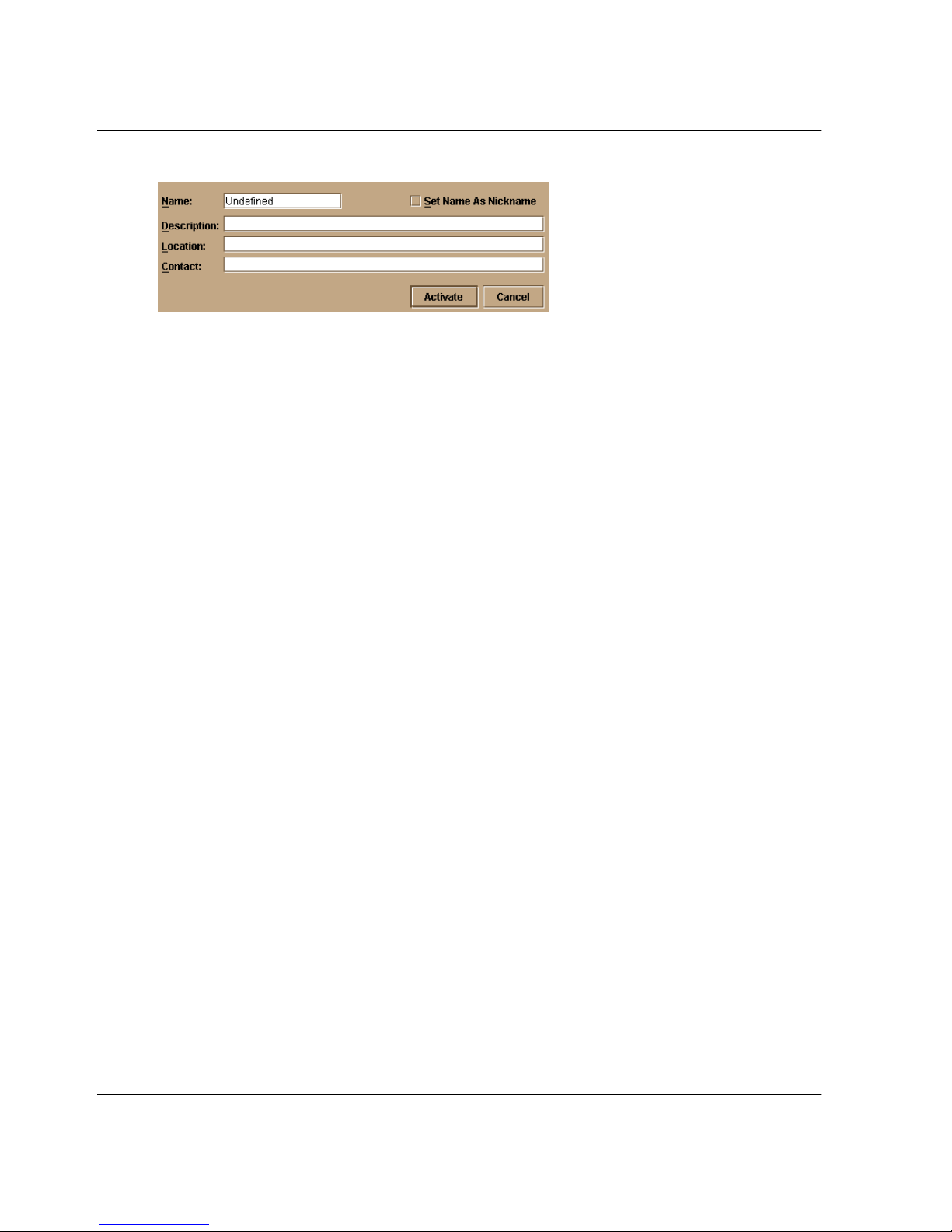
Configuring the Switch
Figure 3–1: Configure Identification dialog box
2. Click in the Name field and enter a name for the switch. The name could reflect
the switch’s Ethernet network domain name service (DNS) host name, if assigned.
3. Click in the Description field and enter a description of the switch.
4. Click in the Location field and enter the location of the switch.
5. Click in the Contact field and enter appropriate information about a contact
person, such as a phone number, title, or e-mail address.
6. Click Set Name as Nickname and add a check mark to the check box if you want
to use the name in the Name field as a nickname for the switch’s WWN. The
nickname will then display instead of the WWN in Product Manager views.
7. Click Activate to save the data and close the dialog box.
8. If you are finished configuring the switch, back up the configuration data. For
more information, refer to Backup and Restore Configuration on page 5-6.
Configure Operating Mode
Use the procedure in this section to change the switch’s operating mode.
Introduction
If the FICON Management Server feature is enabled, the default mode will be set to
S/390. The operating mode cannot be changed to open systems with the FICON
Management Server feature enabled. If the Open Systems Management Server feature
is enabled, the operating mode can be set to either open systems or S/390 mode.
Typically, S/390 mode is used when attaching an IBM S/390 Parallel Enterprise server
to the switch and implementing inband switch management through a Fibre
Connection (FICON) channel.
Use Open Systems mode for all other (non-FICON) Fibre channel environments.
3–2 edge switch 2/16 product manager user guide
Page 95
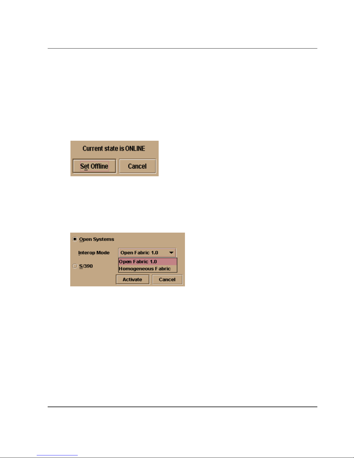
Procedure
To configure the operating mode for the switch, use the following steps:
NOTE: The switch must be offline before you change operating modes.
1. If the switch is not offline:
a. Select Set Online State from the Maintenance menu on the menu bar.
Figure 3–2: Set Online State dialog box (Currently Online)
b. Click Set Offline to set the switch offline as shown in Figure 3–4.
2. Select Operating Mode from the Configuration menu on the menu bar.
Configuring the Switch
The Set Online State dialog box displays as shown in Figure 3–4.
The Configure Operating Mode dialog box displays.
Figure 3–3: Configure Operating Mode dialog box
3. Select either Open Systems or S/390.
•S/390 mode: If the FICON Management Server feature is enabled, the default
mode is S/390. You cannot change to Open Systems mode with the FICON
Management Server feature enabled.
• Open Systems Mode: Select an appropriate interoperability mode from the
Interop Mode drop-down list.
— Open Fabric 1.0 - Default. Select this mode if the fabric contains only
fabric compliant switches. Select this mode for managing heterogeneous
fabrics. We recommend using this mode.
edge switch 2/16 product manager user guide 3–3
Page 96

Configuring the Switch
— Homogeneous Fabric- Select this mode if the fabric contains only HP
switches and directors that are also operating in Homogeneous Fabric
mode.
4. Click Activate to save your changes and to close the dialog box.
5. Set the switch online:
a. Select Set Online State from the Maintenance menu on the menu bar.
b. When the Set Online State dialog box displays, click Set Online to set the
switch online.
Configure Operating Parameters
Use the procedures in this section to configure the following Fibre Channel operating
parameters using the Configure Operating Parameters dialog box.
NOTE: Ordinarily, you do not need to change these values from their defaults. The only
exception is the Preferred Domain ID. Change this value if the switch will participate in a
multiswitch fabric.
• BB_Credit
Configure the switch to support buffer to buffer credit (BB_Credit) from 1
through 60. This is the value used for all ports, except those configured for
extended distance buffering (10-100 km). The default value is 16. For a
description of the buffer-to-buffer credit, refer to industry specification, Fibre
Channel Physical and Signaling Interface.
•R_A_TOV
Configure resource allocation time-out value (R_A_TOV) in tenth-of-a-second
increments. This variable works with the error detect time-out value (E_D_TOV)
variable to control the switch’s behavior when an error condition occurs.
Resources are allocated to a circuit when errors are detected and are not released
for reuse until the time set by the R_A_TOV value expires. The default value is
100 tenths (10 seconds). Set a value between 10 tenths and 1200 tenths (1 through
120 seconds).
NOTE: Set the same value for R_A_TOV on all switches on a multiswitch fabric. If the value is
not the same on all units, the fabric segments. Also, the value for R_A_TOV must be greater
than the value configured for E_D_TOV.
•E_D_TOV
3–4 edge switch 2/16 product manager user guide
Page 97

Configuring the Switch
Adjust the E_D_TOV in one-tenth-second increments. An error condition occurs
when an expected response is not received within the time limit set by this value.
The default value is 20 tenths (2 seconds). Set a value between 2 tenths through
600 tenths (.2 through 60 seconds).
NOTE: Set the same value for E_D_TOV on all switches on a multiswitch fabric. If the value is
not the same, the fabric segments.
•Preferred Domain ID
Use this field to set each switch in the fabric to a unique preferred domain ID.
Fibre Channel addresses in the switch include this preferred domain ID, which
creates a unique identification for the port in the fabric. The default value is 1. Set
a preferred value from 1 through 31.
The preferred domain ID must be unique for each switch in a fabric. If two
switches have the same preferred domain ID, the E_Ports segment, causing the
fabric to segment.
NOTE: For more information on the domain ID, refer to the section on domain ID assignment
for multiswitch fabrics in the
guide for director 2/64, edge switch 2/16, and edge switch 2/32
(A6534-96025/AA-RS2DA-TE).
hp StorageWorks product in a SAN environment: planning
• Switch Priority
Setting this value determines the principal switch for the multiswitch fabric.
Select either Principal (highest priority), Default, or Never Principal (lowest
priority) from the Switch Priority drop-down list.
If all switches are set to Principal or Default, the switch with the highest priority
and the lowest WWN becomes the principal switch. Following are some examples
of principal switch selection when switches have these settings.
• If you have three switches and set all to Default, the switch with the lowest
WWN become the principal switch.
• If you have three switches and set two to Principal and one to Default, the
switch with the Principal setting that has the lowest WWN becomes the
principal switch.
• If you have three switches and set two to Default and one to Never Principal,
the switch with the Default setting and the lowest WWN becomes the
principal switch.
Note that at least one switch in a multiswitch fabric needs to be set as Principal or
Default. If all of the switches are set to Never Principal, all of the interswitch links
(ISLs) will segment. If all but one switch is set to Never Principal and the switch
that was Principal goes offline, then all of the other ISLs will segment.
edge switch 2/16 product manager user guide 3–5
Page 98
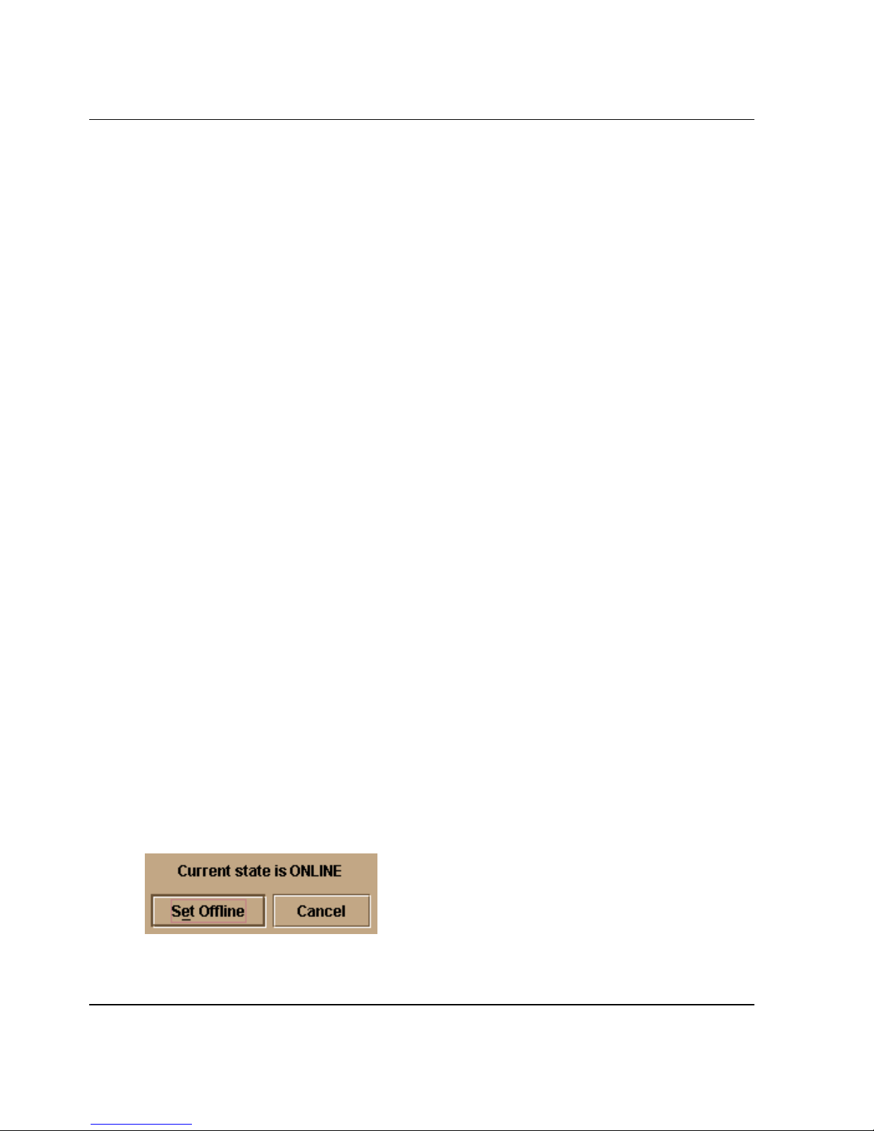
Configuring the Switch
NOTE: We recommend configuring switch priority as Default. If you are considering changing
this value to something other than the default, refer to sections on principal switch selection for
multiswitch fabrics in the hp StorageWorks product in a SAN environment: planning guide for
director 2/64, edge switch 2/16, and edge switch 2/32 (A6534-96025/AA-RS2DA-TE) for details.
In the audit log you may notice that the Principal setting maps to a number code
of 1, Default maps to a number code of 254, and Never Principal maps to a
number code of 255. The number codes 2-253 are no longer in use.
•Rerouting Delay
Placing a check mark in the check box to the left of the Rerouting Delay option
enables rerouting delay. This option is only applicable if the configured switch is
in a multiswitch fabric.
Enabling the rerouting delay ensures that frames are delivered in order through the
fabric to their destination. If there is a change to the fabric topology that creates a
new path (for example, a new switch is added to the fabric), frames may be routed
over this new path if its hop count is less than a previous path with a minimum
hop count. This may result in frames being delivered to a destination out of order
since frames sent over the new, shorter path may arrive ahead of older frames still
in route over the older path.
If rerouting delay is enabled, traffic ceases in the fabric for the time specified in
the E_D_TOV field of the dialog box. This delay allows frames sent on the old
path to exit to their destination before new frames begin traversing the new path.
The operating parameters are stored in NV-RAM on the switch.
Procedure
To configure Fibre Channel operating parameters for the switch, use the following
steps:
1. Configure the switch offline.
NOTE: Setting the switch offline terminates all Fibre Channel connections.
a. Select Set Online State from the Maintenance menu on the menu bar.
Figure 3–4: Set Online State dialog box (Online)
The Set Online State dialog box displays as shown in Figure 3–4.
3–6 edge switch 2/16 product manager user guide
Page 99
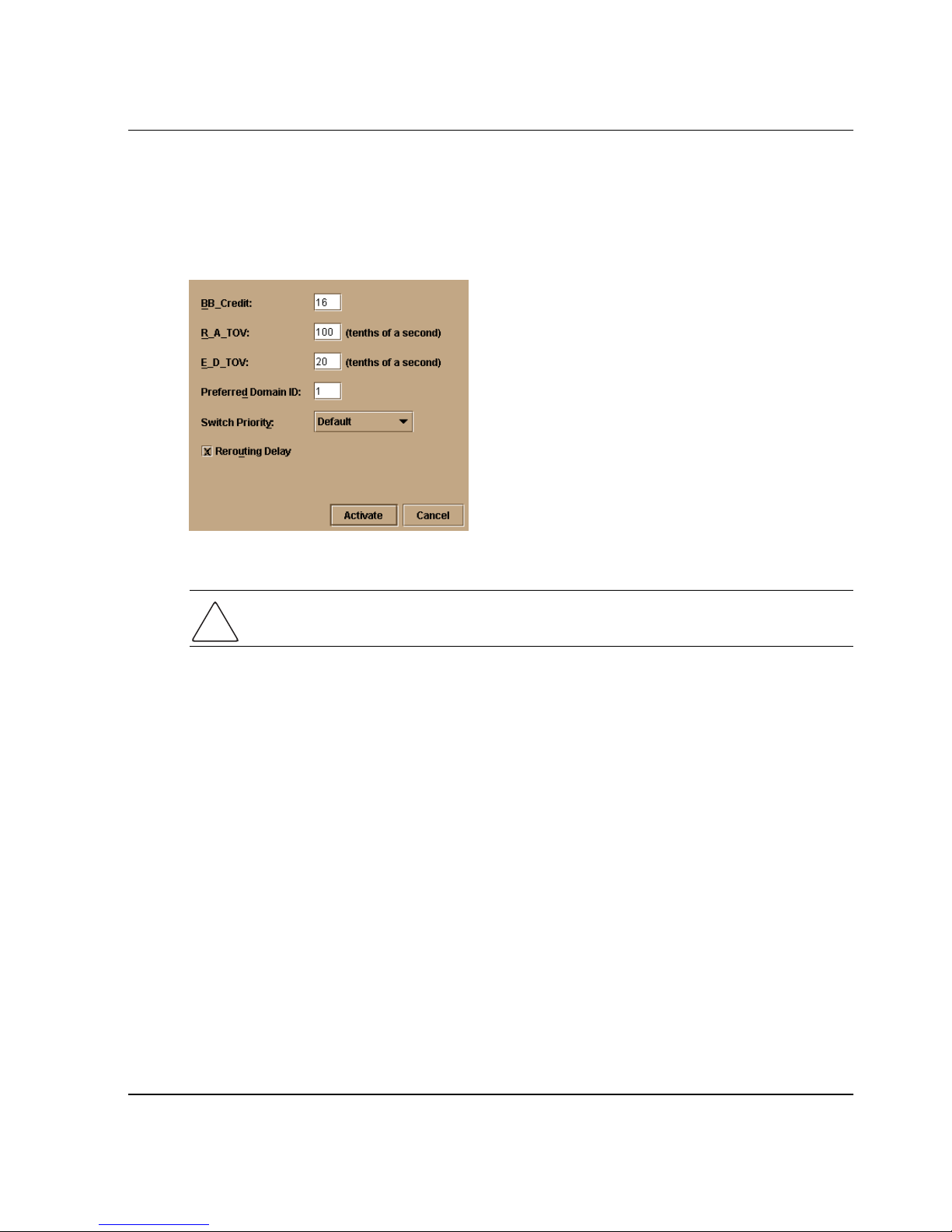
Configuring the Switch
b. Click Set Offline to set the switch offline as shown in Figure 3–4.
2. Select Operating Parameters from the Configuration menu on the menu bar.
The Configure Operating Parameters dialog box displays.
Figure 3–5: Configure Operating Parameters dialog box
CAUTION: Setting the switch offline terminates all Fibre Channel connections.
3. Enter data into dialog box fields.
For a description and the values required for each of the fields that display on the
Configure Operating Parameters dialog box refer to Configure Operating
Parameters on page 3-4.
4. Click Activate to save the configuration and close the dialog box.
5. Set the switch online.
a. Select Set Online State from the Maintenance menu on the menu bar.
b. When the Set Online State dialog box displays, click Set Online to set the
switch online.
6. Back up the configuration data when you are finished configuring the switch. For
more information, refer to Backup and Restore Configuration on page 5-6.
edge switch 2/16 product manager user guide 3–7
Page 100

Configuring the Switch
Configure Ports
Use the procedures in this section to configure names, blocked and unblocked state,
10-100 km extended distance buffering, enable or disable link incident (LIN) alerts for
ports, port type, port speed, Port binding, and WWN binding name.
Port configuration data is stored in NV-RAM on the switch. Configure data in the
following columns of the Configure Ports dialog box:
•Port #
You cannot edit this field. This column identifies the port number. The port
numbers range from 0 through 15.
• Name (open systems mode only)
Enter a name for the port. The port names display in the Port Properties dialog
box and elsewhere in the Product Manager to identify the port.
NOTE: To identify port numbers for which you want to provide names, place the cursor over the
ports in the Hardware View. As you move over a port, a label displays that identifies the slot
number where the port is installed.
To name ports in S/390 mode, use the Configure Addresses dialog box.
• Blocked (opens systems mode only)
Placing a check mark in the check boxes of this column blocks the operation of
the port.
To block ports in S/390 mode, use the Configure Addresses dialog box.
• 10-100Km
This column is for extended distance buffering. You can enable extended distance
for a port even if it is not an extended distance port. However, enabling extended
distance buffering on a port disables the ability for the port to send broadcast
traffic. When you select this option, the port can support up to 60 buffer-to-buffer
credits (BB_Credits) to handle link distances up to 100 km. This enables the port
to process 2K frames from attached devices. If this option is not enabled, the port
uses the BB_Credit (1-60) configured through the Operating Parameters dialog
box.
If a device is connected and logged in to the fabric when extended distance is
enabled or disabled on the corresponding port, the switch will send OLS for 5
milliseconds to force the device to log in again and obtain the new BB_Credit
value set for the port.
3–8 edge switch 2/16 product manager user guide
 Loading...