

Page 1

Installation Guide
HP Workstation zx6000
HP Server rx2600
Manufacturing Part Number : A7857-90020
© Copyright 2002 Hewlett-Packard Company.
Edition E0902
Page 2

Legal Notices
The information contained in this document is subject to change without
notice.
Hewlett-Packard makes no warranty of any kind with regard to this
material, including, but not limited to, the implied warranties of
merchantability and fitness for a particular purpose.
Hewlett-Packard shall not be liable for errors contained herein or for
incidental or consequential damages in connection with the furnishing,
performance, or use of this material.
Hewlett-Packardassumesnoresponsibilityfortheuseorreliabilityofits
software on equipment that is not furnished by Hewlett-Packard.
This document contains proprietary information that is protected by
copyright. All rights are reserved. No part of this document may be
photocopied, reproduced, or translated to another language without the
prior written consent of Hewlett-Packard Company.
Intel® and Itanium® 2 are trademarks or registered trademarks of Intel
Corporation or its subsidiaries in the United States and other countries.
Microsoft®, Windows®, Windows NT®, Windows 2000® and Windows
XP® are registered trademarks of the Microsoft Corporation.
Pentium® and AGPset™ are trademarks of Intel Corporation.
Fire GL™ is a trademark of ATI.
Linux® is a registered trademark of Linus Torvalds.
UNIX is a registered trademark in the United States of America and
other countries, licensed exclusively through X/Open Company Limited.
1980, 1984 AT&T, Inc.
1979, 1980, 1983 The Regents of the University of California.
This softwareanddocumentationisbasedinpartontheFourth Berkeley
Software Distribution under license from the Regents of University of
California.
2
Page 3

Printing History
The manual printing date and part number indicate its current edition.
The printing date will change when a new edition is printed. Minor
changes may be made at reprint without changing the printing date. The
manual part number will change when extensive changes are made.
Printed manual updates may be issued between editions to correct errors
or document product changes. Manuals that are published on the HP
Support website (www.hp.com/go/bizsupport) are updated often, please
visit this website periodically for the most recent versions. To ensure
that you receive the updated or new editions, you should also subscribe
to the appropriate HP product support service. See your HP Sales
Representative for details.
First Edition: July 2002
Printing Division:
Hewlett-Packard Co.
Workstations Division
3404 E. Harmony Rd.
Fort Collins, CO 80525
Printed in the U.S.A.
3
Page 4

4
Page 5

1. Setting Up and Using Your System
System Description . . . . . . . . . . . . . . . . . . . . . . . . . . . . . . . . . . . . . . . . . . . . . . . . . . . . . 14
Features. . . . . . . . . . . . . . . . . . . . . . . . . . . . . . . . . . . . . . . . . . . . . . . . . . . . . . . . . . . . .15
Setting Up Your HP zx6000 or rx2600 System. . . . . . . . . . . . . . . . . . . . . . . . . . . . . . . . 19
Installation Tools . . . . . . . . . . . . . . . . . . . . . . . . . . . . . . . . . . . . . . . . . . . . . . . . . . . . . 19
Connecting Devices . . . . . . . . . . . . . . . . . . . . . . . . . . . . . . . . . . . . . . . . . . . . . . . . . . . . . 21
Audio Accessory Note . . . . . . . . . . . . . . . . . . . . . . . . . . . . . . . . . . . . . . . . . . . . . . . . . . 22
Keyboard and Mouse . . . . . . . . . . . . . . . . . . . . . . . . . . . . . . . . . . . . . . . . . . . . . . . . . . 22
Connecting the Power Cord . . . . . . . . . . . . . . . . . . . . . . . . . . . . . . . . . . . . . . . . . . . . . 22
Graphics Cards . . . . . . . . . . . . . . . . . . . . . . . . . . . . . . . . . . . . . . . . . . . . . . . . . . . . . . . 23
Select a Monitor for your Graphics Card . . . . . . . . . . . . . . . . . . . . . . . . . . . . . . . . . . . . 24
Front Panel. . . . . . . . . . . . . . . . . . . . . . . . . . . . . . . . . . . . . . . . . . . . . . . . . . . . . . . . . . . . 28
System Configuration . . . . . . . . . . . . . . . . . . . . . . . . . . . . . . . . . . . . . . . . . . . . . . . . . . . 29
Extensible Firmware Interface (EFI) . . . . . . . . . . . . . . . . . . . . . . . . . . . . . . . . . . . . . 29
Management Processor (MP) . . . . . . . . . . . . . . . . . . . . . . . . . . . . . . . . . . . . . . . . . . . . 29
Baseboard Management Controller (BMC). . . . . . . . . . . . . . . . . . . . . . . . . . . . . . . . . 30
Internal Component for your System . . . . . . . . . . . . . . . . . . . . . . . . . . . . . . . . . . . . . . . 32
Software and Driver Availability . . . . . . . . . . . . . . . . . . . . . . . . . . . . . . . . . . . . . . . . . . 32
Working in Comfort and Safety. . . . . . . . . . . . . . . . . . . . . . . . . . . . . . . . . . . . . . . . . . . . 33
Preparing Your Work Environment. . . . . . . . . . . . . . . . . . . . . . . . . . . . . . . . . . . . . . . 33
Your Work Posture . . . . . . . . . . . . . . . . . . . . . . . . . . . . . . . . . . . . . . . . . . . . . . . . . . . . 34
Additional Ergonomic Issues . . . . . . . . . . . . . . . . . . . . . . . . . . . . . . . . . . . . . . . . . . . . 35
Contents
2. Troubleshooting Your System
Solving Hardware Problems . . . . . . . . . . . . . . . . . . . . . . . . . . . . . . . . . . . . . . . . . . . . . . 38
Troubleshooting Tips:. . . . . . . . . . . . . . . . . . . . . . . . . . . . . . . . . . . . . . . . . . . . . . . . . . 41
If You Lose the Key. . . . . . . . . . . . . . . . . . . . . . . . . . . . . . . . . . . . . . . . . . . . . . . . . . . . 41
Need More Help?. . . . . . . . . . . . . . . . . . . . . . . . . . . . . . . . . . . . . . . . . . . . . . . . . . . . . . 42
Accessing System Diagnostics. . . . . . . . . . . . . . . . . . . . . . . . . . . . . . . . . . . . . . . . . . . . . 43
Running Support Tools Manager (HP-UX only) . . . . . . . . . . . . . . . . . . . . . . . . . . . . . 43
Running ODE-Based Diagnostics (HP-UX only). . . . . . . . . . . . . . . . . . . . . . . . . . . . . 44
Running TopTools (Linux only) . . . . . . . . . . . . . . . . . . . . . . . . . . . . . . . . . . . . . . . . . . 45
HP e-DiagTools Hardware Diagnostics . . . . . . . . . . . . . . . . . . . . . . . . . . . . . . . . . . . . 46
Using the LEDs and e-buzzer to Troubleshoot Your System. . . . . . . . . . . . . . . . . . . . . 48
Troubleshooting with the LEDs. . . . . . . . . . . . . . . . . . . . . . . . . . . . . . . . . . . . . . . . . . 49
Troubleshooting with the e-buzzer . . . . . . . . . . . . . . . . . . . . . . . . . . . . . . . . . . . . . . . 51
Recovering Your System . . . . . . . . . . . . . . . . . . . . . . . . . . . . . . . . . . . . . . . . . . . . . . . . . 53
HP Customer Care Center Phone Numbers. . . . . . . . . . . . . . . . . . . . . . . . . . . . . . . . . . 54
5
Page 6

Contents
A. Regulatory Information
Regulatory Information . . . . . . . . . . . . . . . . . . . . . . . . . . . . . . . . . . . . . . . . . . . . . . . . . . 57
Federal Communications Commission Radio Frequency Interference Statement (for
USA only) . . . . . . . . . . . . . . . . . . . . . . . . . . . . . . . . . . . . . . . . . . . . . . . . . . . . . . . . . . . 57
Notice for Canada . . . . . . . . . . . . . . . . . . . . . . . . . . . . . . . . . . . . . . . . . . . . . . . . . . . . . 57
Safety Warning for the USA and Canada . . . . . . . . . . . . . . . . . . . . . . . . . . . . . . . . . . 57
Notice for France. . . . . . . . . . . . . . . . . . . . . . . . . . . . . . . . . . . . . . . . . . . . . . . . . . . . . . 58
Notice for the Netherlands. . . . . . . . . . . . . . . . . . . . . . . . . . . . . . . . . . . . . . . . . . . . . . 58
Notice for Germany. . . . . . . . . . . . . . . . . . . . . . . . . . . . . . . . . . . . . . . . . . . . . . . . . . . . 58
Noise Declaration for Germany . . . . . . . . . . . . . . . . . . . . . . . . . . . . . . . . . . . . . . . . . . 59
Notice for Japan (Class A) . . . . . . . . . . . . . . . . . . . . . . . . . . . . . . . . . . . . . . . . . . . . . . 59
Notice for Korea . . . . . . . . . . . . . . . . . . . . . . . . . . . . . . . . . . . . . . . . . . . . . . . . . . . . . . 59
Notice for Taiwan . . . . . . . . . . . . . . . . . . . . . . . . . . . . . . . . . . . . . . . . . . . . . . . . . . . . . 59
B. Warranty Statements
Hardware and Software Warranties . . . . . . . . . . . . . . . . . . . . . . . . . . . . . . . . . . . . . . . 62
Warranty Limitations. . . . . . . . . . . . . . . . . . . . . . . . . . . . . . . . . . . . . . . . . . . . . . . . . . 62
Limitation of Liability and Remedies . . . . . . . . . . . . . . . . . . . . . . . . . . . . . . . . . . . . . 64
Third Party Products . . . . . . . . . . . . . . . . . . . . . . . . . . . . . . . . . . . . . . . . . . . . . . . . . . 64
Customer Responsibilities . . . . . . . . . . . . . . . . . . . . . . . . . . . . . . . . . . . . . . . . . . . . . . 65
Obtaining On-site Warranty Service . . . . . . . . . . . . . . . . . . . . . . . . . . . . . . . . . . . . . . 65
Obtaining Parts Warranty Service. . . . . . . . . . . . . . . . . . . . . . . . . . . . . . . . . . . . . . . . 66
Software Limited Warranty . . . . . . . . . . . . . . . . . . . . . . . . . . . . . . . . . . . . . . . . . . . . . 67
HP Telephone Support Services. . . . . . . . . . . . . . . . . . . . . . . . . . . . . . . . . . . . . . . . . . 68
Supplemental Warranty and Service Support . . . . . . . . . . . . . . . . . . . . . . . . . . . . . . 68
Contacting HP for Warranty Service. . . . . . . . . . . . . . . . . . . . . . . . . . . . . . . . . . . . . . 68
6
Page 7

Important Safety Warnings
Avoiding Electrical Shocks
WARNING To avoid electrical shock, do not open the power supplies. There
are no user-serviceable parts inside.
To avoid electrical shock and harm to your eyes by laser light, do
not open the DVD laser module. The laser module should be
serviced by service personnel only. Do not attempt to make any
adjustment to the laser unit. Refer to the label on the DVD for
power requirements and wavelength. This product is a class I
laser product.
Removing and Replacing the Cover
WARNING For your safety, never remove the system side cover without first
disconnecting the power cord from the power outlet and
removing any connection to a telecommunications network. If a
Power Protection Device is fitted to your system, you must shut
down your computer using its on/off switch, then remove the
power cord before removing the system’s side cover. Remove the
Power Protection Device cables before any servicing operation.
Always replace the side cover before switching the system on
again.
Battery Safety Information
WARNING There is a danger of explosion if the battery is incorrectly
installed. For your safety, never attempt to recharge,
disassemble, or burn an old battery. Replace the battery with the
same or equivalent type, as recommended by the manufacturer.
7
Page 8

The battery in this system is a lithium battery that does not
contain any heavy metals. However, to protect the environment,
do not dispose of batteries in household waste. Return used
batteries either to the shop from which you bought them, to the
dealer from whom you purchased your system, or to HP so that
they can either be recycled or disposed of in the correct way.
Returned batteries will be accepted free of charge.
Avoiding Burn Injuries
WARNING Some parts inside the computer will be hot. Wait approximately
three to five minutes for them to cool down before touching
them.
Avoiding Static Electricity
CAUTION Static electricity can damage electronic components. Turn OFF all
equipment before installing an accessory card. Don’t let your clothes
touch any accessory card. To equalize the static electricity when
replacing an accessory card, rest the accessory card bag on top of the
system unit while you are removing the card from the bag. Handle the
card as little as possible and with care.
Information on Ergonomic Issues
It is strongly recommended that you read the ergonomics information,
available in the “Working In Comfort” section of this manual, before
using your system.
You can access more extensive ergonomics information by connecting to
HP’s web site: www.hp.com/ergo
8
Page 9
Recycling Your System
HP has a strong commitment toward the environment. Your HP system
has been designed to respect the environment as much as possible. HP
can also take back your old system for recycling when it reaches the end
of its useful life. HP has a product take-back program in several
countries. The collected equipment is sent to one of HP’s recycling
facilities in Europe or the U.S.A. As many parts as possible are reused.
The remainder is recycled. Special care is taken for batteries and other
potential toxic substances, these are reduced into non-harmful
components through special chemical processes. If you require more
details about HP’s product take-back program, contact your local dealer
or your nearest HP Sales Office.
Additional Documentation
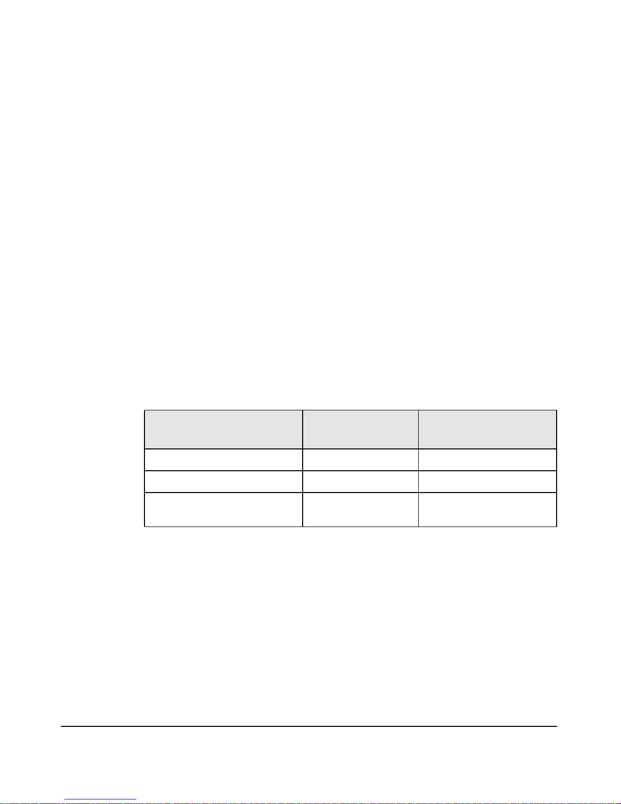
The following table lists the documentation available for this system.
Only selected publications are in hard-copy format. All are available as
PDF files from the HP Web site or on the Documentation CD provided
with your system.
Title
Installation Poster PDF file Yes, A7857-90001
Installation Guide (this book) PDF file Yes, A7857-90020
Operation & Maintenance
Guide
Available at HP
Web site
PDF file (web based) No (on-line, see below)
Hard-copy?
Accessing HP’s World Wide Web Site
Additional online support documentation, firmware upgrades, and
drivers are available from HP’s Web site at
http://www.hp.com/large/pr oducts
After accessing the site, select the appropriate hardware.
9
Page 10
Where To Find The Information
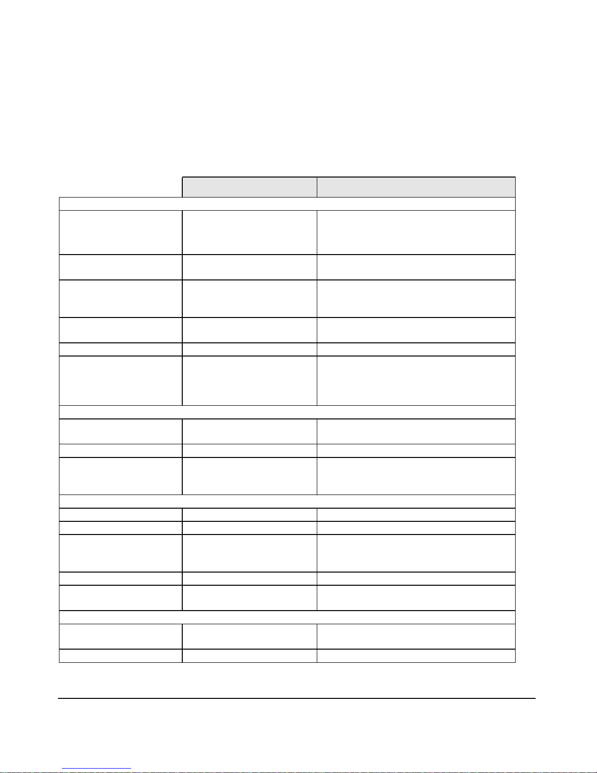
The table below summarizes information provided in the Installation
Guide and the Operation & Maintenance Guide.
Installation Guide
Introducing the Workstation
Product features Minimal Key features.
Environmental Setting up the System.
Working in Comfort.
Safety warnings Basic Safety. Electrical, multimedia, safety,
Finding on-line
information
Technical information Basic details. Advanced.
Formal documents Certificate of Conformity.
Using the Workstation
Connecting devices and
turning on
EFI Basic details.
Fields and their options
within Setup
Upgrading the Workstation
Opening the System Overview Full description.
Supported accessories Full description
Installing accessories Processor(s), memory, accessory boards,
Configuring devices Installing devices.
System board Installing and removing, connectors and
Repairing the Workstation
Troubleshooting Basic Advanced. Hardware diagnoses and
Diagnostic utility Basic HP STM, Monitor diagnostics and ODE.
HP Web sites. HP Web sites.
Software License
Agreement, Hardware
Warranty
Rear panel connectors,
starting and stopping.
Basic details.
Viewing Setup screen,
using, passwords
Operation & Maintenance Guide
Exploded view.
Parts list.
Complete listing.
unpacking, removing, and replacing
cover.
Complete list.
mass storage devices., fans, power
supply, system board, battery
switch settings. Chip-set details.
suggested solutions.
1
1. For address, see “Accessing HP’s World Wide Web Site” on page 9.
10
Page 11

Contents of the Documentation CD
Each zx6000/rx2600 system includes a Documentation CD that contains
PDF files of all the system documentation. To access the files on a
Linux® system, place the CD into the CD-ROM drawer. An introduction
page will appear in your browser.
Instructions for Mounting Documentation CD on HP-UX System
1. Logon as root
2. Determine the CD drive, type: ioscan -fnC disk
3. Make a mount directory, type: mkdir <directoryname>
4. Mount the CD, type:
/etc/mount -o cdcase /dev/dsk/<drive> <directory>
5. View documents with your web browser by entering the following in
your browser’s Location or Address entry box:
file://<directory>/index.htm
Clicking on the individual document titles will launch the Adobe Acrobat
Reader application (also supplied on the CD) and displaythe PDF of that
document. If required, you may print the document from the PDF.
Documents included on the CD are:
1. Installation Poster - poster_<language>.pdf
2. Installation Guide - guide_<language>.pdf
3. Operation and Maintenance guide - opmaint_english.pdf
The Install Poster and Guide are also available on the Documentation
CD in several localized languages.
11
Page 12

12
Page 13

1 Setting Up and Using Your
System
This Guide provides you with essential information on the system, initial
setup tips and basic troubleshooting for your zx6000 or rx2600 system.
Chapter 1 13
Page 14

Setting Up and Using Your System
System Description
System Description
The following table provides an overview of the possible zx6000 and
rx2600 configurations:.
zx6000
Workstation
Rack-mount
3 PCI
1 AGP
rx2600 Server
1
Rack-mount
4 PCI 4 PCI
rx2600 Server
Tower
Features
Accessory
Card Slots
Fan
Type/Speed
Management
Processor
(ECI) Card
Redundant
Hot Swap
Power Supply
zx6000
Workstation
Tower
3 PCI
1 AGP
Quiet/Low Hi Capacity/High Hi Capacity/ High Hi Capacity/High
No Optional Yes Yes
No Optional Yes Yes
1. Must be ordered from HP as a rack-mounted workstation.
2. A rack-mount server can be converted to a Tower with conversion kit that provides
skins and a floor pedestal.
2
Chapter 114
Page 15
Features
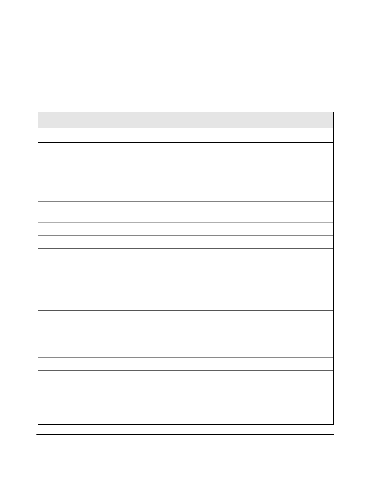
The following table provides an overview of the zx6000 and rx2600
system features:
Feature Description
Setting Up and Using Your System
System Description
Processor(s)
CacheMemory(integrated
in processor package)
Systems can be operated with one or two Intel® Itanium® 2 processors
• Level 0: 16KB
• Level 1: 256KB
• Level 2: 3MB (1.5 MB for 900MHz processor)
Internal Processor Clock
Speed
Chipset HP scalable processor, including a Processor Dependent Hardware
Firmware 8Mb flash EEPROM, write-protected by BMC
Operating System HP-UX and Linux Operating Systems
Main Memory Twelve DIMM sockets that support 256MB, 512MB and 1GB DDR
900MHz and 1GHz
interface, AGP/PCI X host controller and Memory Controller
SDRAM memory modules.
The order in which you install the memory modules is important. For
information on installing memory, see the zx6000/rx2600 Operation &
Maintenance Guide (at www.hp.com/go/bizsupport). You can install a
minimum of 512MB (1 Gb for server configuration) of memory and a
maximum of 12GB.
Mass Storage Four shelves, supporting:
SCSI Controller Two channel Ultra 160 SCSI PCI bus.
IDE Controller Includes an integrated Ultra ATA-100 capable controller that supports
Graphics Controllers
Chapter 1 15
• One front-access, slimline, optical drive.
• Three fast access internal 3 1/2-inch hard disk drives (1-inch
height).
one IDE device.
• NVIDIA Quadro2 EX, NVIDIA Quadro4 900XGL
or
• ATI Radeon 7000, ATI FireGL 8800 and ATI FireGL4
Page 16

Setting Up and Using Your System
System Description
Feature Description
Accessory Card Slots Workstation: One AGP Pro 4X 32-bit slot supporting 1.5V AGP cards
(≤50W) - optional.
Three 64-bit 133MHz Peripheral Component Interconnect (PCI-X) slots,
supporting all bridges and multifunction PCI-X devices. All three PCI-X
slots comply with PCI-X Specification.
Server: Four 64-bit 133MHz Peripheral Component Interconnect
(PCI-X) slots.
NOTE: Hewlett Packard has done extensive testing of PCI, PCI-X, and
AGP cards to ensure proper operation with this system. A full list of HP
supported cards is available at
http://www.hp.com/support/itanium_tpl. If you are considering using a
non-supported card, please review the errata notices at
http://www.hp.com/support/itanium_ipf. These will inform you of any
issues HP is aware of and help ensure that your system remains trouble
free.
Optical Drive Models include either a slimline 8x DVD-ROM/CD-RW combo drive or a
slimline 8x DVD-ROM drive.
System Board Connectors
• One ATA-100 capable IDE connector
• Main power supply connector (plus a redundant power connector)
• Main chassis fan connectors
• Processor fan connectors
• Status panel connector
• Three PCI-X connectors and one AGP card connector for zx6000
and four PCI-X connectors for rx2600 systems. The PCI-X
connectors are 64-bit, 133MHz slots that support all bridges and
multi-function PCI and PCI-X devices.
• Management card (optional)
• Two internal SCSI connectors and one external connector
Management Card
(optional)
• 25-pin Serial connector (with console/remote/USP extensions -
requires breakout cable)
• 15-pin VGA connector
• 10/100 Management LAN
Chapter 116
Page 17

Feature Description
Setting Up and Using Your System
System Description
Rear Connectors
(labeled)
• FourUSB connectors that are all high speed 480Mb/sec. capable as
well as full speed 12 Mb/sec. and low speed 1.5 Mb/sec. HP-UX
supports HP’s USB keyboard and mouse, Linux supports all 1.1
USB devices.
• 9-pin serial (two, buffered)
— Standard: Two UART 16550 buffered serial ports (both
RS-232-C).
— Serial Ports A and B. Note that Serial A Port may be used as
console.
(if one port uses 2xxh, the other port must use 3xxh).
• 10/100 Management LAN and 10/100/1000 LAN
• External SCSI
NOTE The graphics display port functionality on the HP Management
Processor Card (A6875A) is not supported on the HP Workstation zx6000
if the system has an AGP graphics card installed. All other HP
Management Processor Card functionality is supported.
Chapter 1 17
Page 18

Setting Up and Using Your System
System Description
HP zx6000/rx2600 Physical Characteristics
Characteristic Specification
Weight (standard configuration as shipped,
excluding keyboard and display):
Minimum Tower Configuration
Maximum Tower Configuration
Minimum Rack Configuration
Maximum Rack Configuration
Dimensions (same configuration as above):
Tower
Rack mount
Footprint (Tower)
Power Supply
49.4 lbs. (22.4 Kg.)
56.3 lbs. (25.5 Kg.)
38.6 lbs. (17.5 Kg.)
49.0 lbs. (22.2 Kg.)
19.5”H x 11.6”W x 26.5”D
3.4”H x 19.0”W x 26.8”D
2
0.2 m
(2.1 sq ft).
Input voltage (input current, max.)
Input frequency:
Available power (output):
1
Measured input power
Operating Humidity 15% to 80% (relative)
Operating Temperature
Storage Temperature
Over-temperature Shutdown
Altitude:
Operating:
Non-operating
1. In this document, available power and measured input power are
different. Measured input power is the most the system will draw for
the supported configuration. Available power is the maximum power
that the power supply is capable of delivering. As a guideline, cooling
and power specifications should be designed around the measured
input value.
:
100 - 127 VAC, 7.2 A Autoranging
200 - 250 VAC, 3.6 A Autoranging
50/60Hz
600 W
560 W
+5 °C to +35 °C (+41°F to +95°F)
-40°C to +70°C (-40°F to +158°F)
+50° C (+122° F)
10,000 ft. (3048m) max.
15,000 ft. (4600m) max.
NOTE Operating temperature and humidity ranges may vary depending on the
mass storage devices installed. High humidity levels can cause improper
operation of disk drives. Low humidity can aggravate static electricity
problems and cause excessive wear of the disk surface.
Chapter 118
Page 19

Setting Up and Using Your System
Setting Up Your HP zx6000 or rx2600 System
Setting Up Your HP zx6000 or rx2600 System
WARNING If you have any doubt that you can lift the system or monitor
safely, do not try to move them without help.
1. Check the materials list shipped with your system to verify that you
have all of the components necessary for setting up your system.
2. If the system is to be used as a desk-side workstation, place the
system in an area with easily accessible power outlets and enough
space for the keyboard, mouse, and any other accessories.
3. If the system is to be used as a rack-mounted server, please refer to
the rack mounting instructions provided with your rack mount
system.
4. Position the system so that its rear connectors are easily accessible.
Installation Tools
No tools are required to set up your system. However, if you plan to
install or replace an accessory inside your system, you will need a T-10
and T-15 Torx screwdriver or a flat-blade screwdriver. Make sure you use
the Electrostatic Discharge equipment (static-free mat, static strap,
anti-static bags, etc.) to prevent damage to the system.
WARNING Metallic particulates can be especially harmful around
electronic equipment. This type of contamination may enter the
data center environment from a variety of sources, including,
but not limited to, raised floor tiles, worn air conditioning parts,
heating ducts, rotor brushes in vacuum cleaners or printer
component wear. Because metallic particulates conduct
electricity, they have an increased potential for creating short
circuits in electronic equipment. This problem is exaggerated by
the increasingly dense circuitry of electronic equipment.
Chapter 1 19
Page 20

Setting Up and Using Your System
Setting Up Your HP zx6000 or rx2600 System
Over time, very fine whiskers of pure metal can form on
electroplated zinc, cadmium, or tin surfaces. If these whiskers
are disturbed, they may break off and become airborne, possibly
causing failures or operational interruptions. For over 50 years,
the electronics industry has been aware of the relatively rare,
but possible, threat posed by metallic particulate contamination.
During recent years, a growing concern has developed in
computer rooms where these conductive contaminants are
formed on the bottom of some raised floor tiles.
Although this problem is relatively rare, it may be an issue
within your computer room. Since metallic contamination can
cause permanent or intermittent failures on your electronic
equipment, Hewlett-Packard strongly recommends that your site
be evaluated for metallic particulate contamination before
installation of electronic equipment.
Chapter 120
Page 21
Setting Up and Using Your System
Connecting Devices
Connecting Devices
Before connecting any cords or cables to your system, please read the
Warning Notices in the front of this manual.
If you purchased an accessory card that was not installed in your system
at the factory, you must install that card now. To install, refer to the
instructions that came with the card or see the Operation & Maintenance
Guide which is available at: www.hp.com/go/bizsupport.
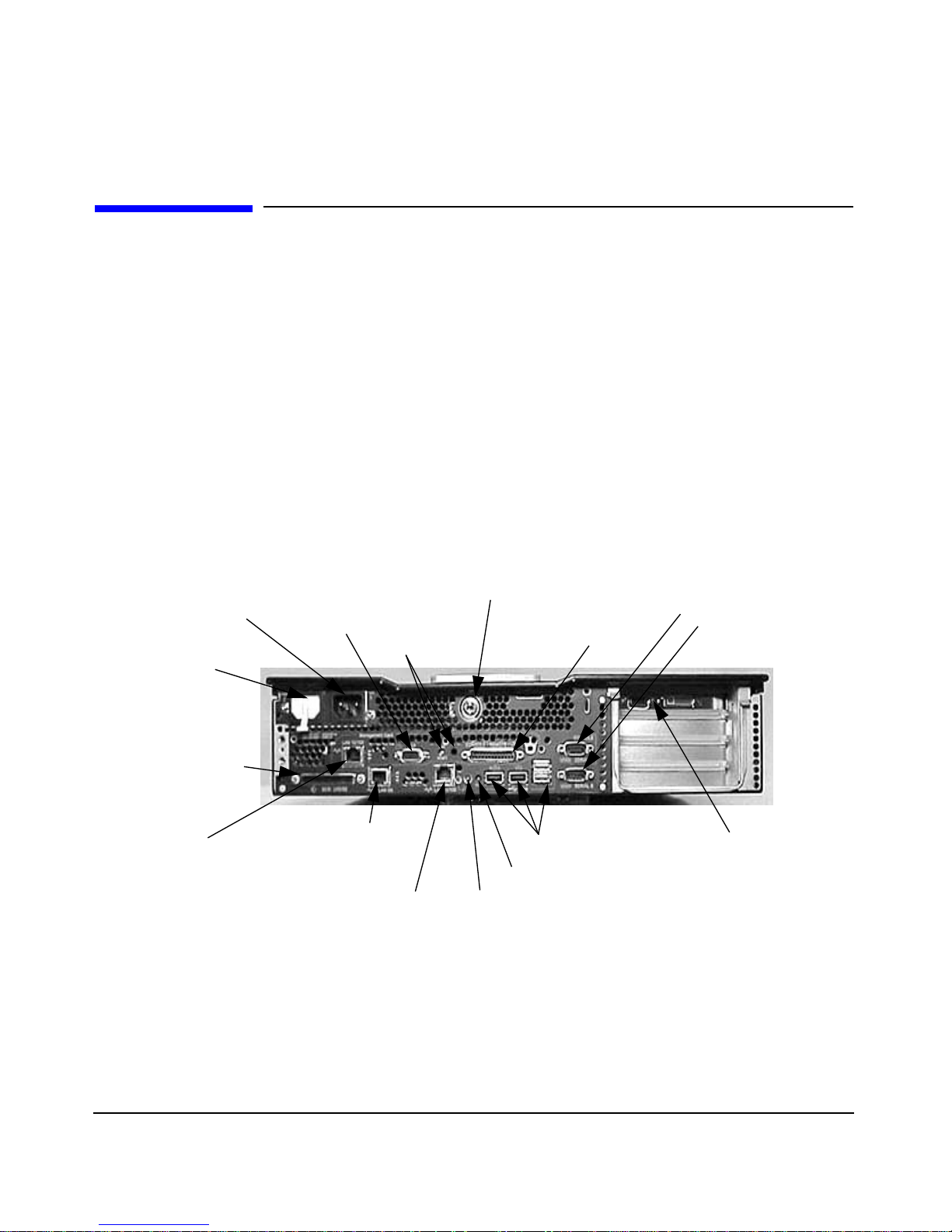
Figure 1-1 shows the rear panel connectors for a rack-mounted rx2600
system. Rear panel connectors for the zx6000 Tower system are similar
but viewed vertically.
Figure 1-1 Rear Panel Connectors on Rack-mounted System with
Management Card
Power
Receptacle (PWR1)
Power
Receptacle
(PWR2)
LVD/SE SCSI
Connector
10/100 Management
LAN*
* Available only if the Management Card (ECI) is installed.
The connectors are shaped to go in one way only. Refer to the sticker on
the back of the machine.
15-Pin VGA
Connector*
MP Reset*
10/100/1000
LAN Connector
10/100 LAN
System Lock
TOC
Locator Button
and LED
25-Pin Serial
Connector*
USB Connectors
Serial Port A (Console)
Serial Port B
Monitor Connector
Chapter 1 21
Page 22
Setting Up and Using Your System
Connecting Devices
Audio Accessory Note
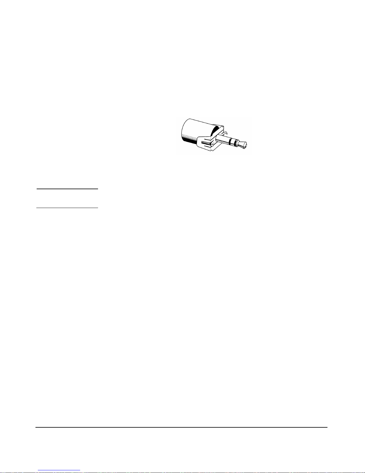
The small steel clip attached to your headset connector (see below)
reduces radio frequency interference and allows your system to meet
international regulatory requirements.
If you connect any other audio accessories to the system, attach one of
these clips to each additional connector as shown.
NOTE Surround sound is not supported on the zx6000 or rx2600 systems.
Keyboard and Mouse
The HP A7861A keyboard and mouse provide the basic input accessories
necessary to get you started with your workstation. The PC-104/105,
-106 key or JIS-109 keyboard is available in 13 different localized
layouts, and fully conforms to industry standards.
The A7861A kit provides a choice of 3-button scroll-wheel mouse
(standard) or 3-button plain mouse (specify product Option 065). Both
the keyboard and the mouse have an extended-length 2.9m (9.5 foot)
cable, which allows more flexible positioning of the system than is
possible with the 1.8m cable on typical PCs. The keyboard and mouse are
connected to the USB connectors on the rear panel of the computer.
Connecting the Power Cord
You will notice that there are two power cord receptacles on the rear
panel of the system. These are redundant receptacles to be used in those
cases where a redundant power supply is required. One of the
receptacles (PWR2) may be covered by a plastic cap (unless you ordered
the second power supply as an option). Plug the power cord into the open
receptacle (PWR1). If you are using redundant power supplies, you may
use both receptacles to achieve redundancy. See the zx6000/rx2600
Operation & Maintenance Guide for complete details.
Chapter 122
Page 23

Setting Up and Using Your System
Connecting Devices
WARNING For your safety always connect equipment to a grounded wall
outlet. Always use a power cord with a properly grounded plug,
such as the one provided with the equipment, or one in
compliance with your national safety standards. This equipment
can be disconnected from the power by removing the power cord
from the power outlet. This means the equipment must be
located close to an easily accessible power outlet.
1. Connect the power cords to the rear of the monitor and the computer.
(The connectors are shaped to go in one way only.)
2. Connect the monitor’s power cord and the computer’s power cord to a
grounded outlet.
Graphics Cards
Your system has three possible operating systems that you can choose
when you purchase it. Depending on the operating system you ordered,
you may have one of the following graphics cards installed:
Table 1-1 Graphics Cards Available for Your System
Type of Card HP-UX Linux
High End/ Extreme 3D ATI FireGL 4 NVIDIA Quadro4
900XGL
Entry 3D NVIDIA Quadro2 EX
Professional 2D ATI Radeon 7000 ATI Radeon 7000
Here is a list of the URLs you can go to for more detailed information
about your graphics card:
• ATI Radeon 7000, FireGL 4 and FireGL 8800 — for more
information, see:
http://www.ati.com/
• NVIDIA Quadro4 900XGL and Quadro2 EX — for more information,
see:
http://www.NVIDIA.com/
Chapter 1 23
Page 24

Setting Up and Using Your System
Select a Monitor for your Graphics Card
Select a Monitor for your Graphics Card
This section provides a list of display resolutions and frequencies for the
graphics cards supported by your system. By using these resolutions and
frequencies you will be able to select the appropriate monitor for your
graphics card. Note that frequencies of 85Hz and higher provide
ergonomic, flicker-free viewing.
If the monitor you select is DDC-2B or DDC-2B+ compliant, the graphics
card will automatically limit itself to those resolutions and frequencies
supported by that monitor. In this case, you do not need to use the tables
in this section to select your monitor.
CAUTION To prevent possible damage to your monitor, make certain you select a
monitor that supports the resolutions and frequencies you wish to use.
Table 1-2 Resolutions and Frequencies for the NVIDIA Quadro2 EX
(Analog Monitors and DB-15 Connector; Linux)
Graphics Card
NVIDIA Quadro2 EX 640×480
1. Only common resolutions are listed. Other intermediate resolutions are possible.
2. The maximum frequency may not be available at all color depths.
Display
Resolution
800×600
1024×768
1280×1024
1600×1200
1920×1200
2048×1536
1
60, 70, 72, 75, 85, 100, 120, 140, 144, 150, 170, 200, 240
60, 70, 72, 75, 85, 100, 120, 140, 144, 150, 170, 200, 240
60, 70, 72, 75, 85, 100, 120, 140, 144, 150, 170, 200, 240
60, 70, 72, 75, 85, 100, 120, 140, 144, 150, 170
60, 70, 72, 75, 85, 100, 120
60, 70, 72, 75, 85, 100
60, 70, 72, 75
Vertical Frequency (Hz)
2
Chapter 124
Page 25

Setting Up and Using Your System
Select a Monitor for your Graphics Card
Table 1-3 Resolutions and Frequencies for the NVIDIA Quadro4 900 XGL
(Analog Monitors with DB-15 Connector; Linux)
Graphics Card
NVIDIA Quadro4
900XGL
1. Only common resolutions are listed. Other intermediate resolutions are possible.
Display
Resolution
640×480
800×600
1024×768
1152×864
1280×960
1280×1024
1600×900
1600×1200
1920×1080
1920×1200
2048×1536
1
60, 70, 72, 75, 85, 100, 120, 140, 144, 150, 170, 200, 240
60, 70, 72, 75, 85, 100, 120, 140, 144, 150, 170, 200, 240
60, 70, 72, 75, 85, 100, 120, 140, 144, 150, 170, 200, 240
60, 70, 72, 75, 85, 100, 120, 140, 144, 150, 170, 200
60, 70, 72, 75, 85, 100, 120, 140, 144, 150, 170
60, 70, 72, 75, 85, 100, 120, 140, 144, 150
60, 70, 72, 75, 85, 100, 120, 140, 144, 150
60, 70, 72, 75, 85, 100, 120
60, 70, 72, 75, 85, 100
60, 70, 72, 75, 85, 100
60, 70, 72, 75
Vertical Frequency (Hz)
2
2. The maximum frequency may not be available at all color depths.
Table 1-4 Resolutions and Frequencies for the NVIDIA Quadro4 900 XGL
(Digital Monitors with DVI Connector; Linux)
Graphics Card
Display
Resolution
1
Vertical Frequency (Hz)
NVIDIA Quadro4
900XGL
1. Only common resolutions are listed. Other intermediate resolutions are
possible.
640×480
800×600
1024×768
1152×864
1280×960
1280×1024
1600×900
1600×1200
60
60
60
60
60
60
60
60
Chapter 1 25
Page 26

Setting Up and Using Your System
Select a Monitor for your Graphics Card
Table 1-5 Resolutions and Frequencies for the ATI Radeon 7000 (Analog
Monitor with DB-15 Connector; HP-UX and Linux)
Graphics Card
ATI Radeon 7000 640×480
Display
Resolution
800×600
1024×768
1152×864
1280×1024
1600×1200
1792×1344
1920×1080
1920×1200
2048×1536
12
60, 72, 75, 85, 90, 100, 120, 160, 200
60, 70, 72, 75, 85, 90, 100, 120, 160, 200
60, 70, 72, 75, 85, 90, 100, 120, 140, 150, 160, 200
60, 70, 75, 80, 85, 90, 100, 120, 150, 160
60, 70, 75, 85, 90, 100, 125, 130, 140
60, 66, 70, 72, 75, 76, 85, 90, 100
60, 75, 80, 85
60, 70, 75, 80, 85, 90
60, 72, 75, 76, 80, 85
60, 66
Vertical Frequency (Hz)
3
1. Only common resolutions are listed. Other intermediate resolutions are possible.
2. Not all resolutions and frequencies are supported on all operating systems.
3. The maximum frequency may not be available at all color depths.
Table 1-6 Resolutions and Frequencies for the ATI Radeon 7000 (Digital
Monitor with DVI Connector; HP-UX and Linux)
Graphics Card
Display
Resolution
12
Vertical Frequency (Hz)
3
ATI Radeon 7000 640×480
800×600
1024×768
1152×864
1280×960
1280×1024
1600×1000
1600×1024
1600×1200
1. Only common resolutions are listed. Other intermediate resolutions are
possible.
60, 75
60, 75
60, 75
60, 75
60, 75
60, 75
60
60
60
2. Not all resolutions and frequencies are supported on all operating systems.
3. The maximum frequency may not be available at all color depths.
Chapter 126
Page 27

Setting Up and Using Your System
Select a Monitor for your Graphics Card
Table 1-7 Resolutions and Frequencies for the ATI FireGL 4(Analog
Monitor with DB-15 Connector; HP-UX)
Graphics Card
ATI FireGL 4 1024×768
1. Only common resolutions are listed. Other intermediate resolutions are
possible.
Display
Resolution
1280×1024
1600×1024
1600×1200
1920×1080
1920×1200
12
Vertical Frequency (Hz)
75, 85
60, 75, 85
75, 85
75, 85
75, 85
75, 85
3
2. Not all resolutions and frequencies are supported on all operating systems.
3. The maximum frequency may not be available at all color depths.
Table 1-8 Resolutions and Frequencies for the ATI FireGL 4 (Digital
Monitor with DVI Connector; HP-UX)
Graphics Card
ATI FireGL 4 1024×768
Display
Resolution
1280×1024
1600×1024
1600×1200
12
Vertical Frequency (Hz)
75
75
75
75
3
1. Only common resolutions are listed. Other intermediate resolutions are
possible.
2. Not all resolutions and frequencies are supported on all operating systems.
3. The maximum frequency may not be available at all color depths.
Chapter 1 27
Page 28
Setting Up and Using Your System
Front Panel
Front Panel
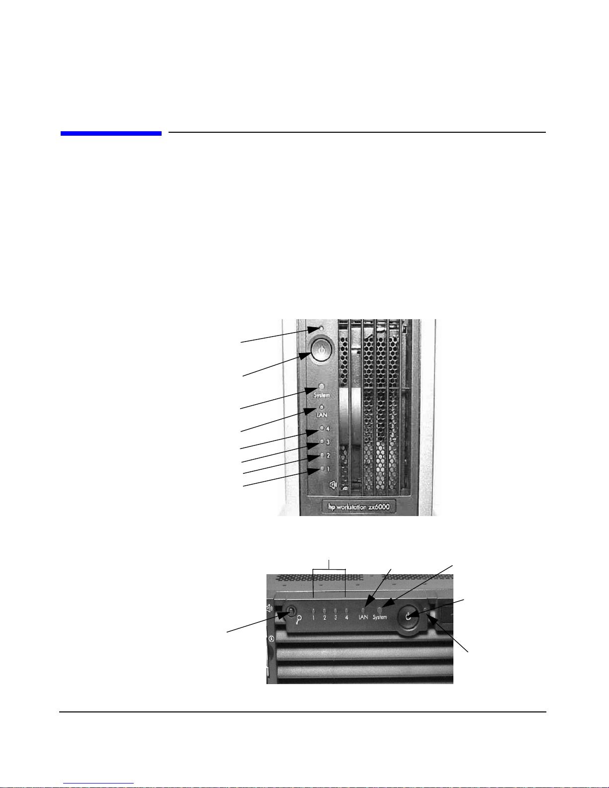
The zx6000/rx2600 front panels have the following features:
• The On/Off LED is green when the power is on, or the power button
is pushed in. If the power is on and the button is pushed in then the
LED will stay on even after the system is powered down. When the
button is released, the green LED will turn off.
• The hard disk drive activity LED is orange during POST and hard
disk drive access. When the system is powered down, the LED is off.
Figure 1-2 Front Panel for the Tower System
Power On/Off
Light
Power On/Off
Button
System LED
LAN LED
Diagnostic
Diagnostic
Diagnostic
Diagnostic
Figure 1-3 Front Panel for the Rack-mounted System
LED 4
LED 3
LED 2
LED 1
Diagnostic
Locator LED and
Button
LEDs 1 through 4
LAN LED
System LED
Power On/Off
Button
Power On/Off
LED
Chapter 128
Page 29

Setting Up and Using Your System
System Configuration
System Configuration
There are three tools available to assist you in setting up your system
configuration - the Extensible Firmware Interface (EFI), Management
Processor (MP) and Baseboard Management Controller (BMC). This
section gives you a brief introduction to these tools. For complete
information, refer to the System Configuration chapter in the
zx6000/rx2600 Operation & Maintenance Guide found at
http://www.hp.com/go/bizsupport web page.
Extensible Firmware Interface (EFI)
The file system supported by the Extensible Firmware Interface is based
on the File Allocation Table (FAT) file system. EFI encompasses the use
of FAT-32 for a system partition. The system partition is required on a
bootable disk for the IA-64 platform.
The system partition can contain directories, data files, and EFI images.
The EFI system firmware may search the \EFI directory of the EFI
system partition, EFI volume, to find possible EFI images that can be
loaded. The HP-UX bootloader is one example of an EFI image.
Complete information on the commands used by the EFI shell are
provided in the zx6000/rx2600 Operation & Maintenance Guide found at
http://www.hp.com/go/bizsupport web page. You can obtain a detailed
description of the commands online by typing help and the command
name at the EFI shell prompt. For example:
shell> help date
Management Processor (MP)
First, make sure that you have the Management Card installed in your
system. To determine if the card is installed, look at the back panel of
your system. Youwill see a 25-pin Serial Port if the Management Card is
installed. See Figure 1-1 on page 21. Complete information on the
Management Processor is found in the System Configuration section of
the zx6000/rx2600 Operation & Maintenance Guide at
http://www.hp.com/go/bizsupport.
Chapter 1 29
Page 30

Setting Up and Using Your System
System Configuration
The Management Processor (MP) is an independent support processor
for the system console. MP provides services that facilitate the
management of the host system. Its major features are:
Table 1-9 MP Features and their Descriptions
Feature Description
Always on capability The MP is alive as long as the power cord is plugged in.
User/password access control The users supported are both operators and
administrator.
Multiple access methods Local Port Use terminal of laptop computer for
direct connect
Remote Port Usededicated modem RS-232 port and
Modem Port External modem
LAN Use telnet or web to access MP LAN
Mirrored console The system console output stream is reflected to all of the
connected console users. Any user can provide input
provided the right console is selected and the serial
console is deselected.
Display and/or logging off The system console, system event logs (chassis codes),
Virtual Front Panel (VFP) and system power and
configuration status provide information for the user.
An independent,
non-mirrored session
Additional features The additional features are: power control, system reset,
This is available form local and modem ports for MP
connection (CSP), or OS login (SE).
and Transfer of Control (TOC).
Baseboard Management Controller (BMC)
The Baseboard Management Controller supports the industry-standard
Intelligent Platform Management Interface (IPMI) specification. This
specification describes the management features that have been built
into the system board. These features include: diagnostics, both local and
remote, console support, configuration management, hardware
management and troubleshooting.
Chapter 130
Page 31

Setting Up and Using Your System
System Configuration
For a complete listing of BMC Commands, see the System Configuration
section in the zx6000/rx2600 Operation & Maintenance Guide found at
http://www.hp.com/go/bizsupport.
Chapter 1 31
Page 32

Setting Up and Using Your System
Internal Component for your System
Internal Component for your System
For complete instructions on how to remove/replace components, see the
zx6000/rx2600 Operation & Maintenance Guide at
www.hp.com/go/bizsupport.
Software and Driver Availability
You can download the latest drivers and firmware for your system.
You can also register to obtain information on new driver availability
automatically.
Contact your dealer for an up-to-date list of supported devices or check
the HP web site: www.hp.com/go/bizsupport.
Chapter 132
Page 33
Working in Comfort and Safety
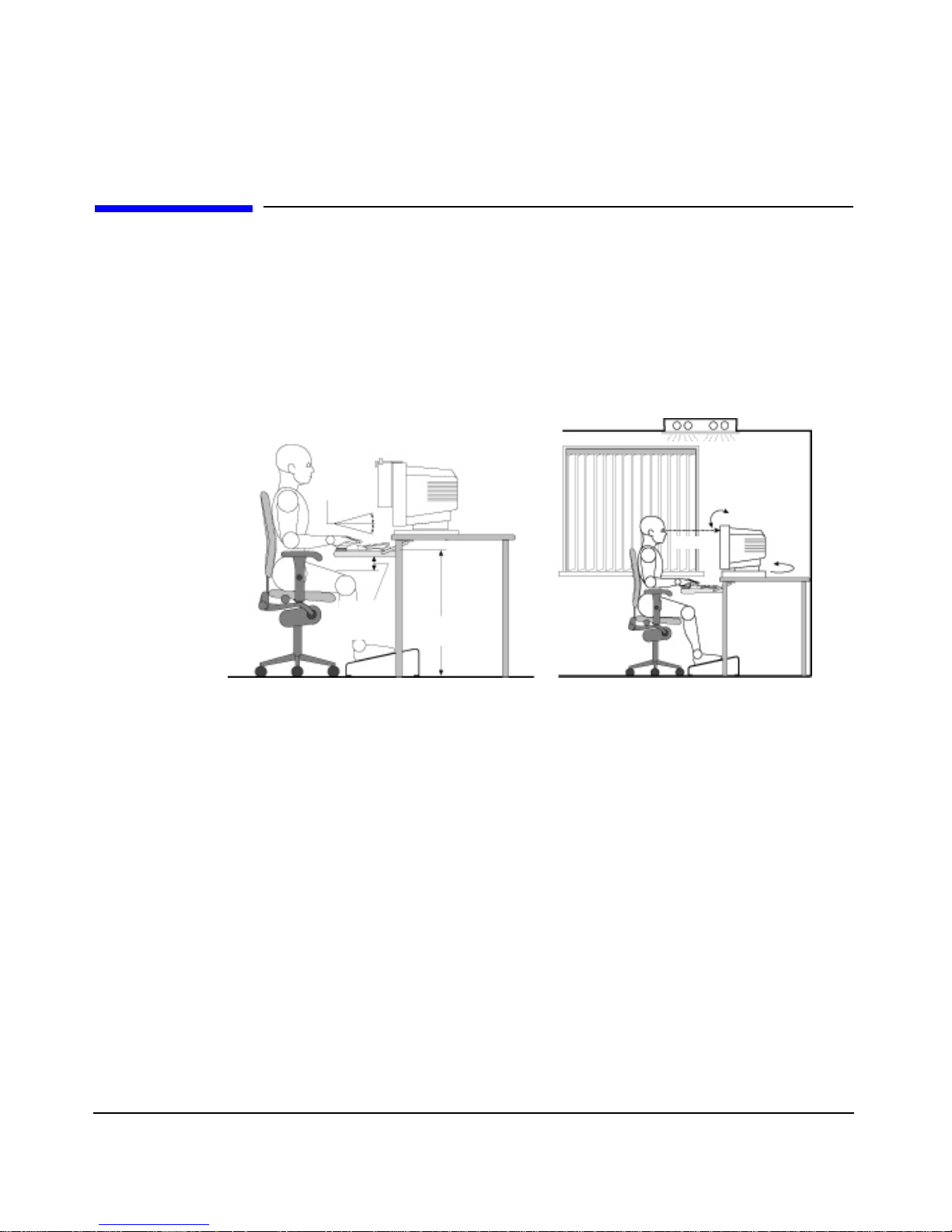
Preparing Your Work Environment
When using HP computing equipment, it is important that your work
environment contributes to your comfort and productivity:
Figure 1-4 Your Work Environment
Document holder
Keyboard
Slope
Setting Up and Using Your System
Working in Comfort and Safety
<15˚
Thigh
Clearance
>6cm
Keyboard Height
64-76 cm
• Work Surface Height. Your work surface should be height adjustable.
Toensure that your work surface is at the correct height, first adjust
the height of your chair so that your feet are firmly on the floor or on
an angled foot rest, then adjust the work surface height until your
forearms are parallel to the floor when you have your fingers on the
keyboard or other input devices.
• Chair. Your chair should provide a comfortable sitting position
including features such as a height and tilt adjustment feature,
curved seat edge, a stable base (for example, five legs and castors,
adjustable back support, a freely rotating swivel, fully adjustable
padded arm rests).
• Monitor. Place your monitor so that the top of the screen is at, or
slightly below, eye level (up to 15 degrees).
• Work Surface Arrangement. Make sure that all elements of your HP
system for example, monitor, document holder, keyboard, mice and
other input devices, and headphones and speakers- are optimally
arranged and adjusted to meet your personal requirements. For
Chapter 1 33
Page 34

Setting Up and Using Your System
Working in Comfort and Safety
example, if you are primarily using the keyboard, place it directly in
front of you, not to the side. If your work involves extensive use of a
mouse or other pointing device, place that device directly in front of
your left or right arm. If you are using both a mouse and keyboard,
place them both at the same work surface height and close together.
If a palm rest is used, the height should be flush with the front edge
of the keyboard. Other items, such as your telephone or notepad,
should also be considered.
CAUTION Various aspects of using mice, keyboards and other input devices may
increase your risk of discomfort or injury. Optimize your comfort and
safety by positioning these devices properly.
Your Work Posture
Sitting in one position for long periods can be uncomfortable. To
minimize the potential risk for physical discomfort or injury, it’s
important that you maintain a proper posture.
• Head. When viewing your monitor, your head should not be tilted
more than 15 degrees forward, and do not turn your head toward
either side.
• Back. While sitting at your work surface, make sure your back is
supported by the chair's backrest in an erect position or angled
slightly backwards.
• Arms. Make sure your arms and elbows are relaxed and loose, with
your upper arms perpendicular to the floor or tilted downward not
more than 15 degrees. Keep your forearms and hands approximately
parallel with the floor with elbows bent between 70 and 115 degrees.
Keep your elbows close to your sides (less than 20 degrees away from
your body).
• Hands, Wrists, Forearms. Try to keep your hands wrists and
forearms in a relaxed neutral position when using your mouse
keyboard or other input devices. For example, while using your
keyboard and mouse, rest your forearms (flat) on your desktop.
• Legs. Your thighs should be horizontal or angled slightly downward.
Your lower legs should be near a right angle to your thighs. Make
sure there is sufficient room under the work surface for your legs.
Chapter 134
Page 35

Setting Up and Using Your System
Working in Comfort and Safety
• Feet. If after adjusting your chair you cannot rest your feet
comfortably on the floor, use a footrest, preferably one that can be
adjusted in height and angle.
Additional Ergonomic Issues
• Look away from the screen from time-to-time to help reduce
eyestrain. Focus on distant objects briefly, and blink periodically to
lubricate your eyes. You also should have your eyes checked on a
regular basis and ensure your eyeglass prescription is suitable for
working on a computer monitor.
• Remember to occasionally shift position and move your body.
Keeping your body in one position for long periods is unnatural and
stressful. When prolonged work is required, take frequent short
breaks. As a rule of thumb, a five or ten minute break every hour is a
good idea. Short frequent breaks are more beneficial than longer less
frequent breaks. Data show that people who work for long periods of
time without a break may be more prone to ergonomic injury.
• Changing tasks frequently will help prevent muscle stiffness.
Examples: alternating between keyboarding, reading, writing, filing,
and moving around in your work environment, helps you maintain a
relaxed posture. Occasionally stretch the muscles in your hands,
arms, shoulders, neck and back. You should stretch at least as often
as you take brief task breaks — at least once every hour.
• Discomfort may be alleviated by using alternative ergonomic designs
and accessories such as ergonomically personalized chairs, palm
rests, keyboard trays, alternative input devices, prescription
eyeglasses,anti-glare screens, and more. Seek additionalinformation
from the sources available to you, including your employer, doctor,
local office supply store, and the Information Sources listed in the
online version of Working in Comfort, pre-loaded on the hard disk of
your HP computing equipment or available on the HP web site:
www.hp.com/ergo
Chapter 1 35
Page 36

Setting Up and Using Your System
Working in Comfort and Safety
Chapter 136
Page 37

2 Troubleshooting Your System
This chapter provides you with essential information on basic
troubleshooting for your HP zx6000/rx2600 system.
Chapter 2 37
Page 38
Troubleshooting Your System
Solving Hardware Problems
Solving Hardware Problems
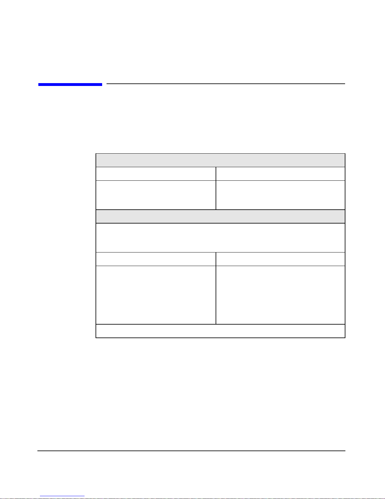
This table gives basic troubleshooting tips. For more in-depth
information, see the section “Accessing System Diagnostics” in this
manual.
Table 2-1 Your System Does Not Start Properly
The system doesn’t power on.
Make sure... How
The system’s power cord is properly
connected.
There is a buzzing noise.
A beep code when the system starts up means that there is a configuration
problem. Many of the ebuzzer codes relate to the LED diagnostic codes. See
section “Using the LEDs and e-buzzer to Troubleshoot Your System”.
Make sure... How
This is the pre-boot diagnostics
capability feature. It detects
problems with your system.
Connect the power cord to a working
power outlet and to the rear of the
system.
1. Count the number of beeps after the
buzzer (refer to the section
“Troubleshooting with the e-buzzer”
in this chapter).
2. Contact HP Support (refer to
page 54).
If you still have a problem, see “Accessing System Diagnostics” on page 43.
Chapter 238
Page 39
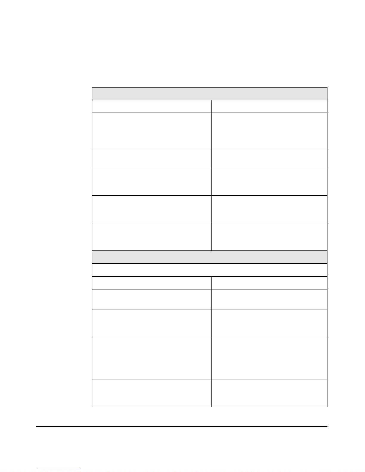
Table 2-2 Your System Has a Hardware Problem
The keyboard doesn’t work.
Make sure... How
Troubleshooting Your System
Solving Hardware Problems
The keyboard cable is correctly
connected.
The keyboard is free of debris. Check all keys are at the same height,
The keyboard itself is not defective. Either replace the keyboard by a
You are using the correct driver. For
other operating systems, refer to your
operating system’s documentation.
You are using the latest firmware. Download the latest firmware from
The monitor doesn’t work.
The system’s power indicator light works but the monitor remains blank
Make sure... How
Plug the cable into the correct
connector on the back of the system.
Color coding is used for easy
matching.
and none are stuck down.
known working unit or try the
keyboard with another system.
Download the latest driver from HP’s
Web at: www.hp.com/go/bizsupport
HP’s Web at:
www.hp.com/go/bizsupport
The monitor is switched ON (LED is
on).
The monitor’s power cord is correctly
connected.
The graphics card is installed and the
monitor (video) cable is correctly
connected.
The monitor’s brightness and contrast
settings are correctly set.
Chapter 2 39
Refer to the monitor manual for an
explanation of the LED signals.
Connect the power cord – ensure it is
plugged into a working grounded
power outlet and into the monitor.
Connect the monitor (video) cable –
ensure it is properly connected to both
the system and the monitor. Ensure
that the cable is connected to the
graphics card’s connector.
Check the settings using the monitor’s
OSD (on-screen display) or using
controls on the front of the monitor.
Page 40
Troubleshooting Your System
Solving Hardware Problems
Table 2-2 Your System Has a Hardware Problem (Continued)
If the system starts and you still have a problem, see “Accessing System
Diagnostics” on page 43.
The mouse doesn’t work.
Make sure... How
The mouse cable is correctly connected.
1. Switch off the system (not
necessary with a USB mouse).
2. Plug the cable into the correct
connector on the back of the
system (color coding is used for
easy matching).
3. Switch on the system.
You are using the correct driver. If you
are using HP’s enhanced mouse, ensure
that the correct driver is installed.
driver is provided with all Linux preloaded
systems.
You are using the latest BIOS Download the latest BIOS from HP’s
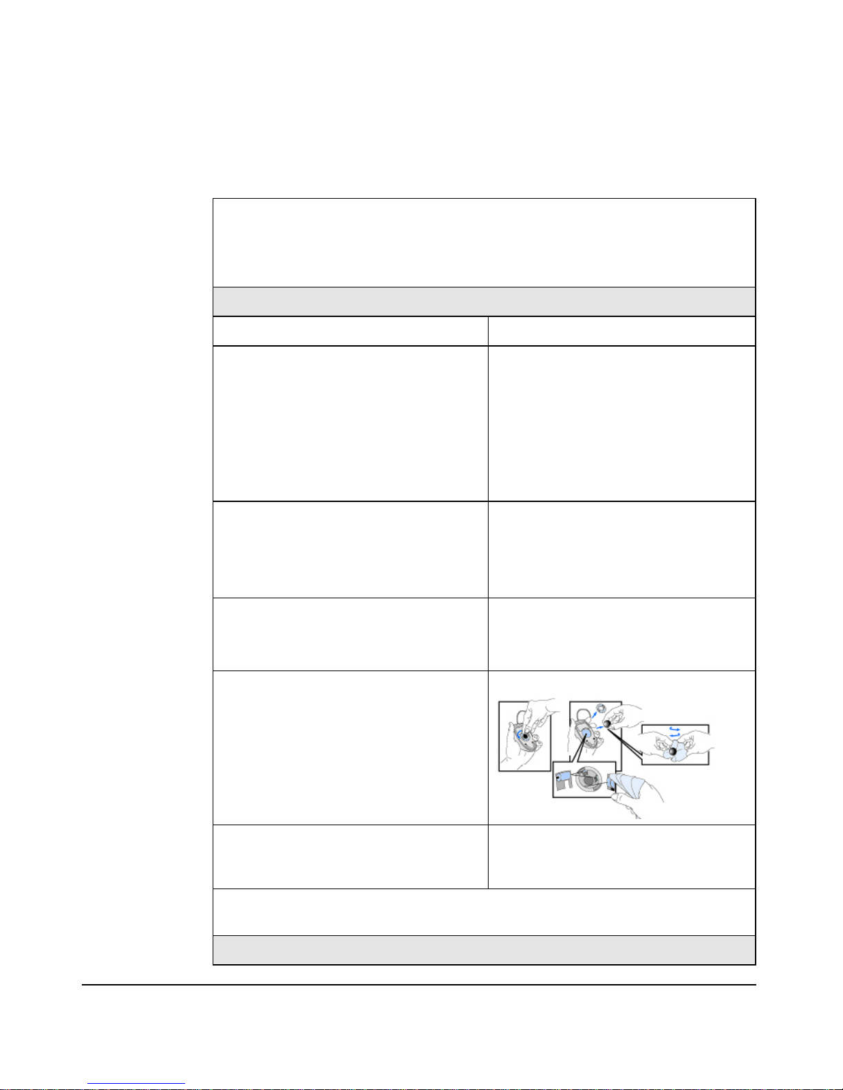
The mouse is clean. Clean the mouse ball as shown below.
This
Download the latest driver from HP’s
Web at:
www.hp.com/go/bizsupport
Web at:
www.hp.com/go/bizsupport
The mouse itself is not defective. Replace the mouse with unit that is
If the system starts but you still have a problem, see “Accessing System
Diagnostics” on page 43.
Your system has no sound.
known to work or try the mouse with
another system.
Chapter 240
Page 41

Troubleshooting Your System
Solving Hardware Problems
Table 2-2 Your System Has a Hardware Problem (Continued)
Check that... How
The lime green Speaker/Headphone
connector is plugged into the
multi-media keyboard.
Either disconnect the lime green
connector to activate the internal
speaker or plug-in headphones or
speaker into the keyboard.
Troubleshooting Tips:
• Restart your system and see if the problem recurs.
• Run the appropriate diagnostic tools. You can create a hardware
profile of your system (Support Ticket) that can be faxed or mailed to
support. Refer to “Accessing System Diagnostics” on page 43 for more
information on using diagnostic tools.
• Visit the HP Support web site www.hp.com/go/bizsupport to see if you
are experiencing a known problem.
• Update your system’s firmware. The latest firmware for your system
and instructions on updating the firmware are available from HP’s
Support web site at:
www.hp.com/large/pr oduct
• Record the details of the problem so that you can describe it
accurately.
• Think of anything you may have done recently before you first
experienced the problem.
• If possible, have your system up and running and close by when you
call HP Support.
• We recommend you contact your HP dealer, or contact HP Support
outside of peak times (mid-morning and week day in the early
evenings).
If You Lose the Key
If you lose the key to the system, you must order a replacement lock (HP
Part Number 5064-9154) from the HP dealer or HP Sales and Service
Office. The new lock is delivered with two keys. Contact your HP dealer
for installing the new lock.
Chapter 2 41
Page 42

Troubleshooting Your System
Solving Hardware Problems
Need More Help?
For more detailed help refer to the zx6000/rx2600 Operation and
Maintenance Guide which is available on HP’s support web site at:
www.hp.com/go/bizsupport
Chapter 242
Page 43

Troubleshooting Your System
Accessing System Diagnostics
Accessing System Diagnostics
To troubleshoot your system, you must be familiar with the HP-UX or
Linux operating systems and be able to start and stop processes. You
should also be familiar with the Offline Diagnostics Environment and
the Support Tools Manager for HP-UX systems and TopTools for Linux.
First, note any event messages and use the diagnostics tool that is
appropriate for your system to determine what failed. Note that event
messages can be found in Appendix D of the zx6000/rx2600 Operation &
Maintenance Guide at http://www.hp.com/go/bizsupport. If a test fails,
the diagnostics message will give you an indication of the Field
Replaceable Unit (FRU) to replace.
For a complete description of the HP-UX diagnostics tools, go to this
URL:
http://docs.hp.com//hpux/diag/
For a complete description of the Linux diagnostic tools, go to this URL:
http://www.hp.com/toptools/
Running Support Tools Manager (HP-UX only)
HP-UX uses an online diagnostics product called the Support Tools
Manager (STM) that allows system operation verification.
Three interfaces are available with the Support Tools Manager: a
command line interface (accessed through the cstm command), a
menu-driven interface (accessed through the mstm command), and the
graphical user interface (accessed through the xstm command).
For more information on these user interfaces, see the online man pages
by entering the following at a command line prompt:
man cstm [Enter]
man mstm [Enter]
man xstm [Enter]
Chapter 2 43
Page 44

Troubleshooting Your System
Accessing System Diagnostics
For information on the enhanced online diagnostics, see the “Support
Tools for HP Computers” documents located at this URL:
http://docs.hp.com//hpux/diag/
To access the Support Tools Manager:
1. In a terminal window, type the following at the fs0:\> prompt to
invoke the command line interface:
2. The following message appears:
3. To verify the system operation, type the following at the CSTM>
prompt:
fs0:\> cstm [Enter]
Support Tool Manager Version A.01.00
Type ‘help’ for a list of available commands.
CSTM>
CSTM> verify all [Enter]
Messages similar to the following appear:
Verification has started on device (CPU).
Verification has started on device (FPU).
CSTM> Verification of (FPU) has completed.
CSTM> Verification of (CPU) has completed.
4. Press [Enter] to return to theCSTM> prompt after all test resultsare
reported.
5. To exit the Support Tools Manager, enter the following:
CSTM> exit [Enter]
Running ODE-Based Diagnostics (HP-UX only)
The Offline Diagnostic Environment (ODE) for HP-UX consists of
diagnostic modules for testing and verifying system operation. ODE
provides all the necessary functions for the user to load specified tests
and interact with those tests.
To boot ODE:
1. Invoke the EFI environment from the system disk or a CD ROM.
Chapter 244
Page 45

Troubleshooting Your System
Accessing System Diagnostics
2. Type ode [Enter] after the fs0:\> prompt to invoke ODE from
the EFI directory on the system disk. The prompt changes to fs0:\>.
Not all of the test modules are available on all systems. To see what test
modules are available to run on this system, type ls at the fs0:\>
prompt. The available modules include the following:
• siodiag – tests and verifies the basic functionality of the SuperI/O
multifunction I/O chip, including serial, parallel, USB, and so forth.
• wdiag – tests and verifies the functionality of the Itanium chip.
• memtest – tests and verifies the memory arrays. If an error is
detected, the diagnostic reports the memory card and its slot number
that needs replacement. It also provides a map of the memory
configuration so that the user can identify the type of memory and its
slot location.
• fupdate – updates the system’s Processor Dependent Code (PDC)
firmware.
• mapper – identifies the configuration of Itanium systems. It displays
path, identification, and revision information of I/O components,
configuration of memory controllers, processors, co-processors, cache,
and TLB, as well as processor board component revisions and values
of various Itanium system identifiers, revisions, and capabilities.
For further information on the various ODE commands and a complete
listing of the command set, type help [Enter] at the fs0:\> prompt or
at the prompt of one of the test modules.
Running TopTools (Linux only)
TopTools is the diagnostics tool that you will use for on-line diagnosis of
systems running the Linux operating systems.
TopTools is a collection of applications and agents designed to provide
device management of Hewlett-Packard computing products. At the
center of the TopTools solution is a device management tool (also
referred to as the Device Manager) that is designed to help you identify
and diagnose network and system problems quickly using a friendly and
intuitive web-based interface. Additional “components” can be installed
that provide management functions for specific device types such as
servers or hubs and switches.
Chapter 2 45
Page 46

Troubleshooting Your System
Accessing System Diagnostics
You can install the TopTools server from the TopTools CD ROM (run
CD:\setup.exe) or from the TopTools web site. The web site is located
at:
http://www.hp.com/toptools
Go to the download page and follow the directions provided. The
TopTools installation wizard (setup.exe) is an extensive program
designed to make the TopTools installation process friendly and
successful.
To open a TopTools console immediately following installation, log into
the TopTools server console as a local administrator, a domain
administrator or as the TopTools user (for whichever account you
specified during the installation process). Double-click the TopTools
shortcut placed on the system.
Self-paced training for TopTools is available on the TopTools web site at:
ftp://ftp.hp.com/pub/toptools/T raining/start.html
HP e-DiagTools Hardware Diagnostics
Your system came with a CD containing HP e-DiagTools hardware
diagnostic utilities. These tools may be used to diagnose
hardware-related problems on your HP system.
NOTE Run e-DiagTools before contacting HP for Warranty service. This is to
obtain information that will be requested by a Support Agent.
With this utility you can:
• Check the hardware configuration and verify that it is functioning
correctly.
• Test individual hardware components.
• Diagnose hardware-related problems.
• Obtain a complete hardware configuration.
• Provide precise information to an HP support agent so they can solve
problems quickly and effectively.
Chapter 246
Page 47

Troubleshooting Your System
Accessing System Diagnostics
Starting HP e-DiagTools
1. Makesure your system model matches the CD-ROM (the CD-ROM is
locked to a specific system model).
2. Insert the HP Drivers and Diagnostics CD in the CD-ROM drive.
3. Restart the system.
4. Select the CD-ROM boot option from the EFI startup menu.
NOTE If you are unable to boot from your CD-ROM drive, restart your
system and check the boot options from the Boot Options
Maintenance Menu to ensure that your system is configured to boot
from the CD-ROM.
5. Press F2 [Continue] at the e-DiagTools introductory screen to access
the Main Menu.
Running HP e-Diagtools and Producing a Support Ticket
To produce a complete record of your system’s configuration and test
results, you will need to create a Support Ticket. This is a simple text file
that contains essential information and is designed to assist yourlocal or
HP Support Agent.
To produce a Support Ticket, from the e-DiagTools Main Menu:
1. Select 2 - Run e-Diagtools to run the diagnostics on your system if you
have not already done so.
2. Select 4 - Support Ticket to create the ticket.
• To save the Support Ticket, press 4.
• To view the Support Ticket, click the button at the bottom of the
screen.
• To exit the Support Ticket tool, press 3.
For more information about the e-DiagTools utility, refer to the
Operation & Maintenance Guide, available on the HP web site at:
http://www.hp.com/go/bizsupport/
Chapter 2 47
Page 48
Troubleshooting Your System
Using the LEDs and e-buzzer to Troubleshoot Your System
Using the LEDs and e-buzzer to Troubleshoot
Your System
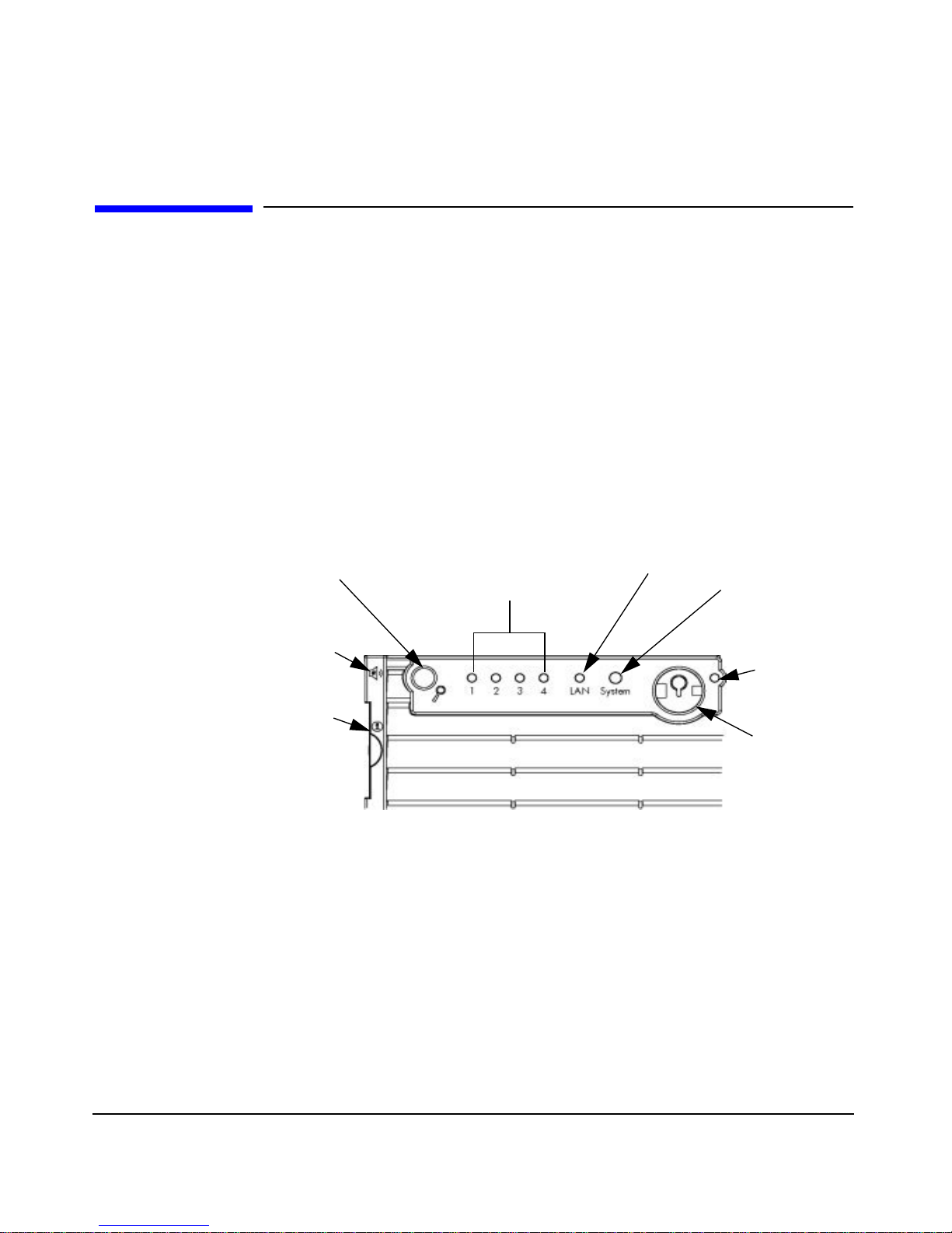
There is a set of four LEDs located on the desk-side and rack-mount
system’s front panel that are used for diagnosing the health of the
system. These LEDs warn of any impending failures and allow you to
take preventive action. For example, you may want to make a system
backup or replace a system component before it quits functioning. The
other four LEDs are the Power, System, LAN, and Locator LEDs. This
section explains how the system’s LEDs can be used for troubleshooting
system problems and how to locate the system you want to work on
within a rack of systems.
Figure 2-1 Rack-mounted System’s LEDs and Buttons
Locator Button/LED
e-buzzer
Icon (hold
phone
here)
System
Information
Card
Diagnostic LEDs
LAN LED
System LED
Power
On/Off
LED
Power
Button
Chapter 248
Page 49
Using the LEDs and e-buzzer to Troubleshoot Your System
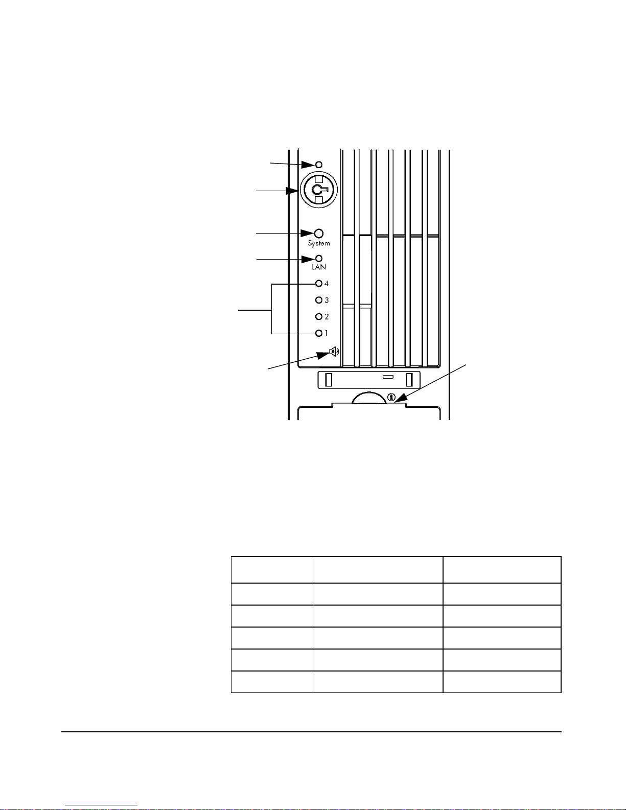
Figure 2-2 Desk-side System’s LEDs and Buttons
Power ON/Off LED
Power Button
System LED
LAN LED
Diagnostic
LEDs
Troubleshooting Your System
e-buzzer Icon
(hold phone here)
Information
Card
Troubleshooting with the LEDs
Power and System LEDs
The Power and System LEDs indicate the state of the system. Here is a
table of these states:
Table 2-3
Power LED System LED State
Off Off Off
On (green) Solid green Running
On (green) Off Booting
System
Chapter 2 49
On (green) Blinking orange (1/sec.) Attention
On (green) Blinking red (2/sec.) Fault
Page 50

Troubleshooting Your System
Using the LEDs and e-buzzer to Troubleshoot Your System
LAN LED
The LAN LED provides an indication as to whether the system is
communicating over the LAN. If the LED is not green, the system is off,
and therefore, the system is not communicating over the LAN. If the
LAN LED is solid green, there is no system LAN communication taking
place, but the system is ready to communicate over the LAN. If the LAN
LED is blinking green, the system is communicating over the LAN.
Locator LED and Button (Rack-mounted Systems only)
The locator LED provides a means for locating the system on which you
intend to work. For example, you find out that system number 5 in your
rack of systems has a LAN cable that needs to be replaced. This will
require that you walk all the way around to the back of your rack of
systems to replace the cable. Once you get behind the rack of systems,
you need to locate the system that needs the cable replaced. The locator
LED makes this easier. When the locator button is pressed in, the locator
LED begins to flash blue at a frequency of one blink per second both on
the front of the system and the back, thus making it easy to locate the
system on which you need to work.
The locator LED can also be activated or deactivated by use of thelocator
button on the back panel of the system or by use of a Management
Processor (MP) command.
Diagnostic LEDs
There are four diagnostic LEDs located on the front bezel of your system.
They are labeled one through four
NOTE The zx6000 HP Workstation boot progress is indicated by LEDs 1-4.
During the boot-up the LEDs will turn on in sequence until the EFI
prompt is reached. These LEDs will be off if there is a Management
processor in the workstation.
WARNING The rx2600 HP Server boot process will be monitored by the
Management Processor Card and not by the LEDs. Refer to the
Management Card section for more details.
Chapter 250
Page 51
Troubleshooting Your System
Using the LEDs and e-buzzer to Troubleshoot Your System
The Troubleshooting section of the zx6000/rx2600 Operation &
Maintenance Guide found at http://www.hp.com/go/bizsupport provides a
table with a list of faults associated with the various possible LED
lighting sequences.
Troubleshooting with the e-buzzer
When your system starts up, the system firmware performs pre-boot
diagnostics to test your hardware configuration for any problems. If a
problem is detected during pre-boot, the pre-boot diagnostics will emit an
audio signal through the workstation’s internal speaker.
The pre-boot diagnostics emits an audio sequence with two kinds of
sounds. The first is an unusual series of tones that indicate an anomaly
has been detected. This series of sounds also contains an electronic
signal that can be sent through a telephone line to an authorized Help
Desk or HP Support, if necessary. This signal cannot be interpreted by
the human ear. However, it can be decoded by Help Desk equipment to
extract the workstation model, serial number and details about any
faults. To send this signal to HP Support, you need to hold your
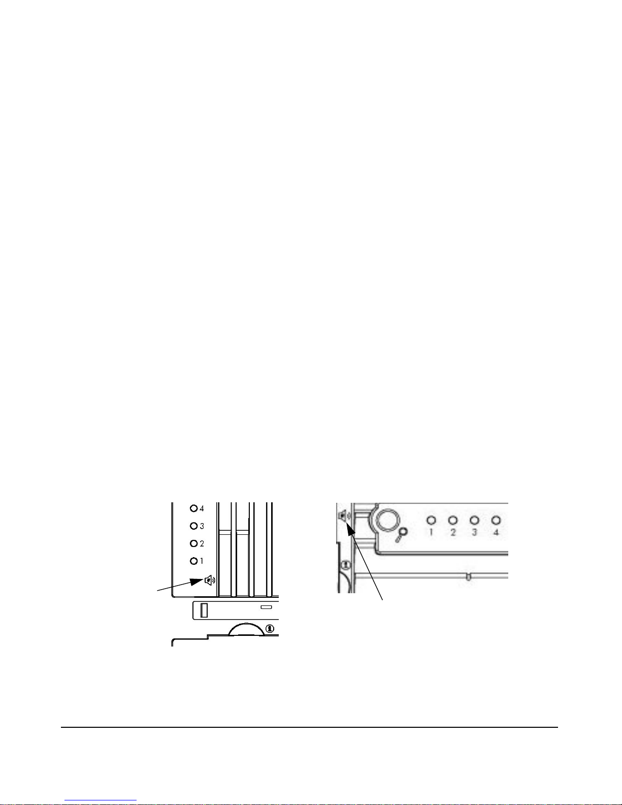
telephone next to the e-buzzer Icon on the system’s front panel. See
Figure 2-3
Figure 2-3 e-buzzer Label for Desk-side and Rack-mounted Systems
Desk-side System’s Bezel
Rack-mounted System’s Bezel
e-buzzer
Icon
e-buzzer Icon
Chapter 2 51
Page 52

Troubleshooting Your System
Using the LEDs and e-buzzer to Troubleshoot Your System
The second type of sound is a series of long beeps that indicate a
particular error. If you hear a series of beeps, you should count them as
this will help you detect the cause of the problem. Here is the meaning of
the number of beeps you hear.
Table 2-4 Description of Beep Codes
Number of
Beeps
1 Processor Processor absent, not correctly connected or ZIF socket
2 Power Supply Power supply is in protected mode; replace the power
3 Memory No memory, bad memory modules or incompatible
4 Video Card Graphics card problem
5 PCI Card PCI card problem; replace the PCI card.
6 Firmware Corrupted firmware. You need to activate crisis recovery
7 System Board Defective system board
FRU to Replace Meaning
not closed; see the associated e-buzzer codes in the section
“Diagnostic LEDs” in this chapter
supply.
memory module
procedure
If You Miss the Beep Code
If you miss the beep code, send the signal again by pressing the power
supply button for 3 seconds and release it once the sound begins.
Chapter 252
Page 53

Troubleshooting Your System
Recovering Your System
Recovering Your System
The HP-UX HP Recovery CD or the HP Enablement Kit for Linux will
enable you to restore your computer to its original factory configuration
and reinstall drivers or other factory-supplied software components. The
drivers and software utilities, including documentation and navigational
aids, help you to recover the pre-loaded software. There are two
CD-ROMs:
• a HP-UX Recovery CD-ROM or HP Enablement Kit for Linux CD
• a Diagnostics CD-ROM
Complete instructions on how to perform an Operating System re-install
or full recovery are found in the booklets that accompany the CD-ROM
media. For more information go to http://hp.com/go/bizsupport.
CAUTION Using the Recovery CD-ROM will permanently erase the current
contents of your hard disk. You should always backup your data and
personal files before using the Recovery CD-ROM
Chapter 2 53
Page 54

Troubleshooting Your System
HP Customer Care Center Phone Numbers
HP Customer Care Center Phone Numbers
HP Customer Care Centers can help you solve issues related to HP
products and, if necessary, initiate appropriate service procedures.In the
U.S.A, telephone support is available 24 hours a day, 7 days a week.
Elsewhere, it is available during normal officehours. Here is the URL for
HP Customer Care Center phone numbers:
http://www.hp.com/cpso-support/guide/psd/expectations.html
Chapter 254
Page 55

A Regulatory Information
Appendix A 55
Page 56

Regulatory Information
Declaration of Conformity
according to ISO/IEC Guide 22 and EN 45014
Manufacturer: Hewlett-Packard Company
3404 East Harmony Rd.
Fort Collins, CO 80528
USA
Declares that the:
Product Type: Computer Workstation/Server
Marketing Designation(s): zx6000, rx2600
Regulatory Model Number: FCLSA-0201
Product Options: all
conforms to the following specifications:
Safety IEC 60950:1991+A1+A2+A3+A4/EN 60950:1992+A1+A2+A3+A4
IEC 60825-1:1993/EN60825-1:1994+A11 Class 1 for LED’s and Lasers
U.S.A 21CFR Subpart J – for FC Laser module
China GB4943-1995
Russia GOST R 50377-92
EMC CISPR 22: 1997 / EN 55022: 1998 Class A
CISPR 24: 1997 / EN 55024: 1998
Also compliant with...
EN 61000-3-2: 1998
EN 61000-3-3: 1995
EN 61000-4-2: 1999 - 4 kV CD, 8 kV AD
EN 61000-4-3: 1996 - 10 V/m for server version (restricted USB peripherals)
3 V/m for workstation version
EN 61000-4-4: 1995 - 2 kV Signal, 4 kV Power Lines
EN 61000-4-5: 1995 - 1 kV Differential mode, 2 kV Common mode
EN 61000-4-8: 1993 - 3 A/m
EN 61000-4-11: 1994
U.S.A FCC Part 15, Class A
Japan VCCI Class A
Australia/New Zealand AS/NZS 2046:1997, AS/NZS 3548:1995
China GB9254-1988
Region of Taiwan CNS 13438:1997 Class A
Russia GOST R 29216-94
and is certified or verified by:
UL Listed to UL1950, 3nd edition, File E146385
cUL Listed to CSA 22.2 No. 950-M93
TUV Certified to EN60950 2nd edition with A1+A2+A3+A4
HP Fort Collins CCQD HTC
supplementary information:
The product herewith complies with the requirements of the Low Voltage Directive 73/23/EEC and the EMC directive
89/336/EEC and carries the CE marking accordingly.
This product was tested in a typical Hewlett-Packard system configuration.
For Compliance Information ONLY, contact: European Contact: Hewlett-Packard, HQ-TRE, Herrenberger
Strasse 140, D-71034 Boeblingen (FAX: +49-7031-14-3143)
Americas Contact: Hewlett-Packard, TCD Quality Manager., 3404 E. Harmony Road, Fort Collins, CO 80528, U.S.A.
(FAX: (970) 898-4556)
Appendix A56
Page 57

Regulatory Information
Regulatory Information
Regulatory Information
Federal Communications Commission Radio
Frequency Interference Statement (for USA only)
This equipment has been tested and found to complywith the limitsfor a
Class A digital device, pursuant to Part 15 of the FCC Rules and the
Canadian Department of Communications. These limits are designed to
provide reasonable protection against harmful interference when the
equipment is operated in a commercial environment. This equipment
generates, uses, and can radiate radio frequency energy and, if not
installed and used in accordance with the instruction manual, maycause
harmful interference to radio communications. Operation of this
equipment in a residential area is likely to cause harmful interference in
which case the user will be required to correct the interference at his own
expense.
Hewlett-Packard’s FCC Compliance Tests were conducted with
HP-supported peripheral devices and HP shielded cables, such as those
you receive with your system. Changes or modifications not expressly
approved by Hewlett-Packard could void the user’s authority to operate
the equipment.
Notice for Canada
This Class A digital apparatus meets all requirements of the Canadian
Interference-Causing Equipment Regulations.
Cet appareil numérique de la Class A respecte toutes les exigences du
Règlement sur le matériel brouilleur du Canada.
Safety Warning for the USA and Canada
If the power cord is not supplied with the computer, select the proper
power cord according to your local national electric code.
USA: use a UL listed type SVT detachable power cord.
Canada: use a CSA certified detachable power cord.
Appendix A 57
Page 58

Regulatory Information
Regulatory Information
For your safety, never remove the system’s cover without first removing
the power cord and any connection to a telecommunication network.
Always replace the cover before switching on again.
Si le cordon secteur n’est pas livré avec votre ordinateur, utiliser un
cordon secteur en accord avec votre code electrique national.
USA: utiliser un cordon secteur “UL listed,” de type SVT.
Canada: utiliser un cordon secteur certifié CSA.
Pour votre sécurité, ne jamais retirer le capot de l’ordinateur sans avoir
préalablement débranché le cordon secteur et toute connection à un
réseau de télecommunication. N’oubliez pas de replacer le capot avantde
rebrancher le cordon secteur.
Notice for France
Il y a danger ïexplosion s’il y a remplacement incorrect de la batterie.
Remplacer uniquement avec une batterie du même type ou ïun type
equivalent recommandé par le constructer. Mettre au rebut les batteries
usagées conformément aux instructions du fabricant.
Notice for the Netherlands
Bij dit apparaat zijn batterijen geleverd. Wanneer deze leeg zijn, moet U
ze niet weggooien maar inleveren als KCA.
Notice for Germany
Wenn die Batterie nicht korrekt eingebaut wird, besteht
Explosionsgefahr. Zu ihrer eigenen Sicherheit sollten Sie nicht
versuchen, die Batterie wiederaufzuladen, zu zerlegen oder die alte
Batterie zu verbrennen. Tauschen Sie die Batterie nur gegen den
gleichen oder ähnlichen Typ aus, der vom Hersteller empfohlen wird. Bei
der in diesem PC intergrierten Batterie handelts sich um eine
Lithium-Batterie, die keine Schwermetalle enthält. Batterien und
Akkumulatoren gehören nicht in den Hausmüll. Sie verden vom
Hersteller, Händler oder deren Beauftragten kostenlos
zurückgenommen, um sie einer Verwertung bzw. Entsorgung
zuzuführen.
Appendix A58
Page 59
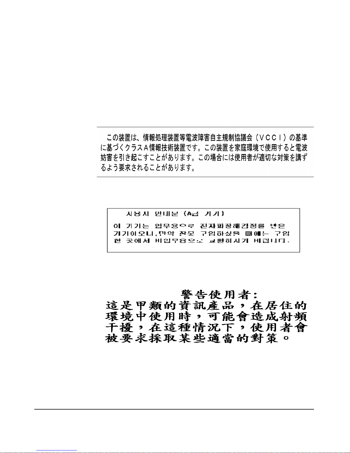
Regulatory Information
Regulatory Information
Noise Declaration for Germany
Lärmangabe nach Maschinenlärmverordnung - 3 GSGV (Deutschland)
LpA < 70 db am Arbeitsplatz normaler Betrieb nach EN27779: 11.92.
Notice for Japan (Class A)
Notice for Korea
Notice for Taiwan
Appendix A 59
Page 60

Regulatory Information
Regulatory Information
Appendix A60
Page 61

B Warranty Statements
IMPORTANT This is your product warranty statement. Read it carefully.
Appendix B 61
Page 62

Warranty Statements
Hardware and Software Warranties
Hardware and Software Warranties
Hewlett-Packard(HP) warrants this hardwareproduct against defects in
materials and workmanship under normal use, for a period of three (3)
years from receipt by the original end-user purchaser or date of
purchase. This is the warranty duration or period.
This warranty covers the following HP Product(s):
1. HP zx6000 Workstation - 1 year, next day on-site
2. HP rx2600 Server - 1 year, next day on-site
This limited warranty includes: phone-in hardware support, parts, labor
and, when needed, next-day on-site response for the duration of the
warranty period. Parts and service are to be provided by an HP Service
Center or a participating Authorized HP Computer Dealer Repair
Center.
Warranty terms may be different in your country. If so, your Authorized
HP Dealer or Hewlett-Packard Sales and Service Office can give you
details.
Warranty Limitations
If HP receives notice of above defined defects during the warranty period,
HP will either,at its option, repair or replace products,which prove to be
defective. Should HP be unable to repair or replace the product within a
reasonable amount of time, the customer's alternate exclusive remedy
shall be a refund of the purchase price upon return of the product to HP.
Only the system processor unit (SPU), keyboard, mouse, and all
Hewlett-Packard accessories installed inside the system processor unit
—such as video adapters, mass storage devices, and interface
controllers— are covered by this warranty. HP products external to the
system processor unit - such as external mass storage subsystems,
displays, printers, and other peripherals - are covered by the applicable
warranties for those products.
A hardware accessory is a hardware product, specifically designated, and
supported, for use with the HP workstation, that is added on or
integrated into an HP workstation in order to provide higher
performance, capacity or increased capability; and is listed as a product
Appendix B62
Page 63

Warranty Statements
Hardware and Software Warranties
in HP’s Corporate Price List. Upon installation inside an HP
workstation, the warranty that came with the accessory applies.
HP is not responsible for defects resulting from: a) improper or
inadequate calibration or maintenance, b) software, interfacing parts or
supplies not supplied by HP, c) unauthorized modification or misuse, d)
operation outside the published environmental specification for the
product, e) in-transit damage, e) improper site preparation or
maintenance.or f) defects resulting from use of non-HP software,
accessories, media, supplies,consumables, or such items not designedfor
use with the product.
Reloading the bundled or pre-loaded software on your workstation is not
covered by the HP warranty. HP products may contain remanufactured
parts equivalent to new in performance or may have been subject to
incidental use.
TO THE EXTENT ALLOWED BY LOCAL LAWS, THE ABOVE
WARRANTY IS EXCLUSIVE AND NO OTHER WARRANTY OR
CONDITION, WHETHER WRITTEN OR ORAL, IS EXPRESSED OR
IMPLIED WITH RESPECT TO THIS PRODUCT. HP SPECIFICALLY
DISCLAIMS ANY IMPLIED WARRANTIES OR CONDITIONS OF
MERCHANTIBILITY, SATISFACTORYQUALITY, AND FITNESS FOR
A PARTICULAR PURPOSE. SOME STATES, PROVINCES OR
COOUNTRIES DO NOT ALLOW LIMITATIONS ON HOW LONG AN
IMPLIED WARRANTY LASTS, SO THE ABOVE LIMITATION OR
EXCLUSION MAY NOT APPLY TO YOU.
This warranty is extended worldwide under certain conditions (please
check with your local HP office) to products purchased from HP or an
Authorized HP Computer Dealer which are reshipped by the original
purchaser either for use by the original purchaser or provided as an
incidental part of systems integrated by the original purchaser. When
available in the country of use, service is provided in the same manner as
if the product was purchased in that country and can only be provided in
countries where the product is designed to operate. If the product is not
normally sold by HP in the country of use, it must be returned to the
country of purchase for service. Response time for on-site service, and
parts delivery turn-around time for parts service, are subject to changes
Appendix B 63
Page 64

Warranty Statements
Hardware and Software Warranties
from standard conditions based upon non-local parts availability.
This warranty gives you specific legal rights, and you may also have
other rights, which vary, from state to state, province to province or
country to country.
Limitation of Liability and Remedies
THE REMEDIES PROVIDED ABOVE ARE THE CUSTOMER'S SOLE
AND EXCLUSIVE REMEDIES. IN NO EVENT SHALL HP OR ITS
SUPPLIERS BE LIABLE FOR LOSS OF DATA OR FOR ANY DIRECT,
INDIRECT, SPECIAL, INCIDENTAL, OR CONSEQUENTIAL
DAMAGES, WHETHER BASED ON WARRANTY, CONTRACT, TORT,
OR ANY OTHER LEGAL THEORY.Some countries,states, or provinces
do not allow the exclusion or limitation of incidental or consequential
damages. If so, the above limitation or exclusion may not apply to you.
The foregoing limitation of liability shall not apply in the event that any
HP product sold hereunder is determined by a court of competent
jurisdiction to be defective and to have directly caused bodily injury,
death, or property damage; provided, that in no event shall HP's liability
for property damage exceed the greater of $50,000 or the purchase price
of the specific product that caused such damage.
Some states, provinces or countries do not allow the exclusion or
limitation of incidental or consequential damages —including lost
profit— so the above limitation or exclusion may not apply to you.
THE WARRANTYTERMS AND CONDITIONS CONTAINEDHEREIN,
EXCEPT TO THE EXTENT LAWFULLY PERMITTED, DO NOT
EXCLUDE, RESTRICT OR MODIFY, AND ARE IN ADDITION TO,
THE MANDATORY STATUTORY RIGHTS APPLICABLE TO THE
SALE OF THIS PRODUCT TO YOU.
Third Party Products
HP does not warrant the performance, quality, form or content of
third-party hardware or software. HP does not warrant third-party
documentation that may be distributed with the workstation. These
products may be warranted by the third-party and HP provides such
products “as is.” On-site visits caused by third-party software or
Appendix B64
Page 65

Warranty Statements
Hardware and Software Warranties
hardware are subject to standard per-incident travel and labor charges.
Customer Responsibilities
The customer is responsible for the security of its proprietary and
confidential information on this system and for maintaining a procedure
external to the products for reconstruction of lost or altered files, data, or
programs (i.e. backups).
For on-site responses, the customer must provide: access to the product;
adequate working space and facilities within a reasonable distance of the
product; access to and use of all information and facilities determined
necessary by HP to service the product; and operating supplies and
consumables such as the customer would use during normal operation.
A representative of the customer must be present at all times during
on-site responses. The customer must state if the product is being used
in an environment which poses a potential health hazard to repair
personnel; HP or the servicing dealer may require that the product be
maintained by customer personnel under direct HP or dealer
supervision.
Obtaining On-site Warranty Service
Support can be obtained from: U.S. and Canada - 1-800-593-6631.
For Worldwide locations, visit:
http://www.hp.com/cpso-support/guide/psd/cscus.html
You will be asked to provide the product model number and serial
number and may be required to provide dated proof of purchase.
During the on-site warranty period, customer-replaceable components
may be serviced through expedited part shipment. In this event, HP will
prepay shipping charges, duty, and taxes; provide telephone assistance
on replacement of the component when necessary; and pay shipping
charges, duty, and taxes for any part that HP asks to be returned.
On-site visits caused by non-Hewlett-Packard products —whether
internal or external to the system processor unit— are subject to
standard per-incident travel and labor charges.
Appendix B 65
Page 66

Warranty Statements
Hardware and Software Warranties
On-site service for this product is restricted or unavailable in certain
locations. In HP Excluded Travel Areas— areas where geographical
obstacles, undeveloped roads, or unsuitable public transportation
prohibit routine travel— service is provided on a negotiated basis at
extra charge.
Response time for HP on-site service in an HP Service Travel Area is
normally next business day (excluding HP holidays) for HP Travel Zones
1-3 (generally 100 miles or 160 Km from the HP office). Response time is
second business day for Zones 4 and 5 (200 miles, 320 Km); third
business day for Zone 6 (300 miles, 480 Km); and negotiated beyond Zone
6 (greater than 300 miles). Worldwide Customer Support Travel
information is available from any HP Sales and Service Office.
Travel restrictions and response time for dealer or distributor service are
defined by the participating dealer or distributor.
Service contracts which provide after-hour or weekend coverage, faster
response time, or service in an Excluded Travel Area are often available
from HP, an authorized dealer, or authorized distributor at additional
charge.
Obtaining Parts Warranty Service
The customer may be responsible for installing the replacement part and
restoring any operating system, applications, or data. HP may, at its
option but is not obligated to, repair the product at the customer’s
premises or “on-site.” If HP is unable to repair or replace the product, the
customer will be entitled to a refund of the purchase price upon return of
the product/parts.
Appendix B66
Page 67

Warranty Statements
Hardware and Software Warranties
When parts warranty service applies, the customer may be required to
run HP-supplied diagnostic programs before an on-site visit or
replacement part will be dispatched.
The customer shall return some defective parts upon HP demand. In
that case, HP will prepay shipping charges for parts returned to the HP
Parts Service Center.
Software Limited Warranty
HP warrants for a one (1) year period from the date of purchase, that the
workstation operating system software will not fail to execute its
programming instructions due to defects in materials and workmanship
when all files are properly installed and used on HP workstations.
HP does not warrant that the operation of software products will be
uninterrupted or error free.
Customer remedies shall be, at HP’s option, replacement of the media or
refund of purchase price based upon return of the product.
Removable Media (if supplied). HP warrants the removable media, if
supplied, upon which the software product is recorded to be free from
defects in materials and workmanship under normal use for a period of
ninety (90) days from the date of purchase. In the event the mediaproves
to be defective during the warranty period, the customer’s remedy shall
be to return the media to HP for replacement. Should HP be unable to
replace the media within a reasonable amount of time, the customer’s
Appendix B 67
Page 68

Warranty Statements
Hardware and Software Warranties
alternative remedy shall be a refund of the purchase price uponreturn of
the product and destruction of all other non-removable media copies of
the software product.
HP Telephone Support Services
HP provides free telephone support for your workstation during the
warranty period. This service will also provide technical assistance with
the basic configuration and setup of your HP workstation and for the
bundled or pre-loaded operating system.
HP does NOT provide telephone support for workstations configured as
network servers. We recommend HP NetServers for your network server
requirements.
Supplemental Warranty and Service Support
Enhanced hardware warranty services, such as after-hour or weekend
coverage, faster response, on-site repair, and service in a HP-excluded
travel area, may be available from HP at an additional charge.Contact
the HP Customer Support Center at 1-800-593-6631for Itanium
Workstations.
Contacting HP for Warranty Service
Worldwide:
Refer to: http://www.hp.com/cpso-support/guide/psd/expectations.html
United States and Canada:
Support can be obtained from: 1-800-593-6631.
Appendix B68
 Loading...