

Page 1

Filename: S70naug.doc Title: S70 Monitor
Template: HP-Print.dot Author: WASSER, Inc. Last Saved By: WASSER, Inc.
Revision #: 6 Page: 1 of 28 Printed: 05/13/99 11:33 AM
S70 Monitor Guide
Page 2

The information contained in this document is subject to change without notice.
Hewlett-Packard® Company makes no warranty of any kind with regard to this material, including, but not
limited to, the implied warranties of merchantability and fitness for a particular purpose.
HP shall not be liable for errors contained herein or for incidental or consequential damages in connection
with the furnishing, performance, or use of this material.
HP assumes no responsibility for the use or reliability of its software on equipment that is not furnished by HP.
This document contains proprietary information that is protected by copyright. All rights are reserved. No part
of this document may be photocopied, reproduced, or translated to another language without the prior written
consent of HP.
Hewlett-Packard Company
Home Products Division
P.O. Box 4010
Cupertino, CA 95015-4010
Printed in the USA.
© Copyright Hewlett-Packard Company, 1999. All rights reserved.
Hewlett-Packard is a registered trademark of Hewlett-Packard Company in the United States of America and
other countries.
The ENERGY STAR name is a U.S. Registered mark of the U.S. Environmental Protection Agency.
Other brand or product names are trademarks of their respective holders.
Filename: S70naug.doc Title: S70 Monitor
Template: HP-Print.dot Author: WASSER, Inc. Last Saved By: WASSER, Inc.
Revision #: 6 Page: 2 of 28 Printed: 05/13/99 11:33 AM
Page 3

Contents
Introduction ........................................................ 1
Precautions ........................................................ 2
Features .............................................................. 4
Specifications .....................................................5
Control Locations and Functions ..................7
Controls and Adjustments............................. 8
Connections ..................................................... 12
Pin Assignments and Signal Levels ........... 14
Timing Charts .................................................. 15
Troubleshooting.............................................. 18
Automatic Power Saving Description......... 19
Contents
iii
Filename: S70naug.doc Title: S70 Monitor
Template: HP-Print.dot Author: WASSER, Inc. Last Saved By: WASSER, Inc.
Revision #: 6 Page: 3 of 28 Printed: 05/13/99 11:33 AM
Page 4

Introduction
Congratulations on your purchase of a HewlettPackard Multi-Frequency monitor. One of the
most versatile monitors available today, the S70
automatically adjusts its vertical and horizontal
scanning frequencies to those of your computer’s
graphics adapter. The
and vivid color graphic displays when used with
Multi-Frequency and compatible graphics adapters
(see specifications).
provides crisp text
S70
Filename: S70naug.doc Title: S70 Monitor
Template: HP-Print.dot Author: WASSER, Inc. Last Saved By: WASSER, Inc.
Revision #: 6 Page: 1 of 28 Printed: 05/13/99 11:33 AM
Introduction
1
Page 5

Precautions
To prevent electric shock do not remove screws
or back cover.
There are no user-serviceable parts inside the
monitor. Refer servicing to qualified service
personnel.
DO NOT REMOVE THE TILT/SWIVEL BASE!
The input power source:
The monitor is designed to be Full Range from
AC 100V to AC 240V.
Always connect the display to a grounded,
three-prong power outlet. Use only the factorysupplied power cord.
Do not put the monitor or other heavy objects
on the power supply cord. A damaged power
cord may cause fire or electric shock.
Do not insert objects into the monitor. They may
cause fire or failure.
Do not allow liquids to fall into the cabinet.
Warning:
2
S70 Monitor Guide
Filename: S70naug.doc Title: S70 Monitor
Template: HP-Print.dot Author: WASSER, Inc. Last Saved By: WASSER, Inc.
Revision #: 6 Page: 2 of 28 Printed: 05/13/99 11:33 AM
This appliance should be grounded.
Page 6

To reduce eye fatigue, avoid using the display
1
in direct sunlight or other bright lights.
If the monitor does not operate properly, turn off
5
the power switch and then unplug the monitor.
Do not operate the monitor beyond the
2
specified temperature and humidity range
(see specifications).
For proper operation, keep the monitor
3
adequately ventilated.
Keep the monitor away from transformers,
4
motors, fans or strong magnetic fields.
When an irregular supply is applied, a protection
6
circuit will turn off the monitor (the power
indicator will also be turned off). If this happens,
turn off the power switch and wait at least
30 seconds before turning it on again.
Filename: S70naug.doc Title: S70 Monitor
Template: HP-Print.dot Author: WASSER, Inc. Last Saved By: WASSER, Inc.
Revision #: 6 Page: 3 of 28 Printed: 05/13/99 11:33 AM
Precautions
3
Page 7
Features
1
Automatically scans horizontal frequencies
ranged from 30kHz to 70kHz and vertical
frequencies ranged from 50Hz to 100Hz.
2
Meets DPMS and NUTEK power-saving standards.
3
All functions can be controlled by On-Screen
Display.
4
Plug-and-play compatibility.
5
Full-scan display–15.9-inch diagonal viewable
image size.
6
Rotation (tilt control).
7
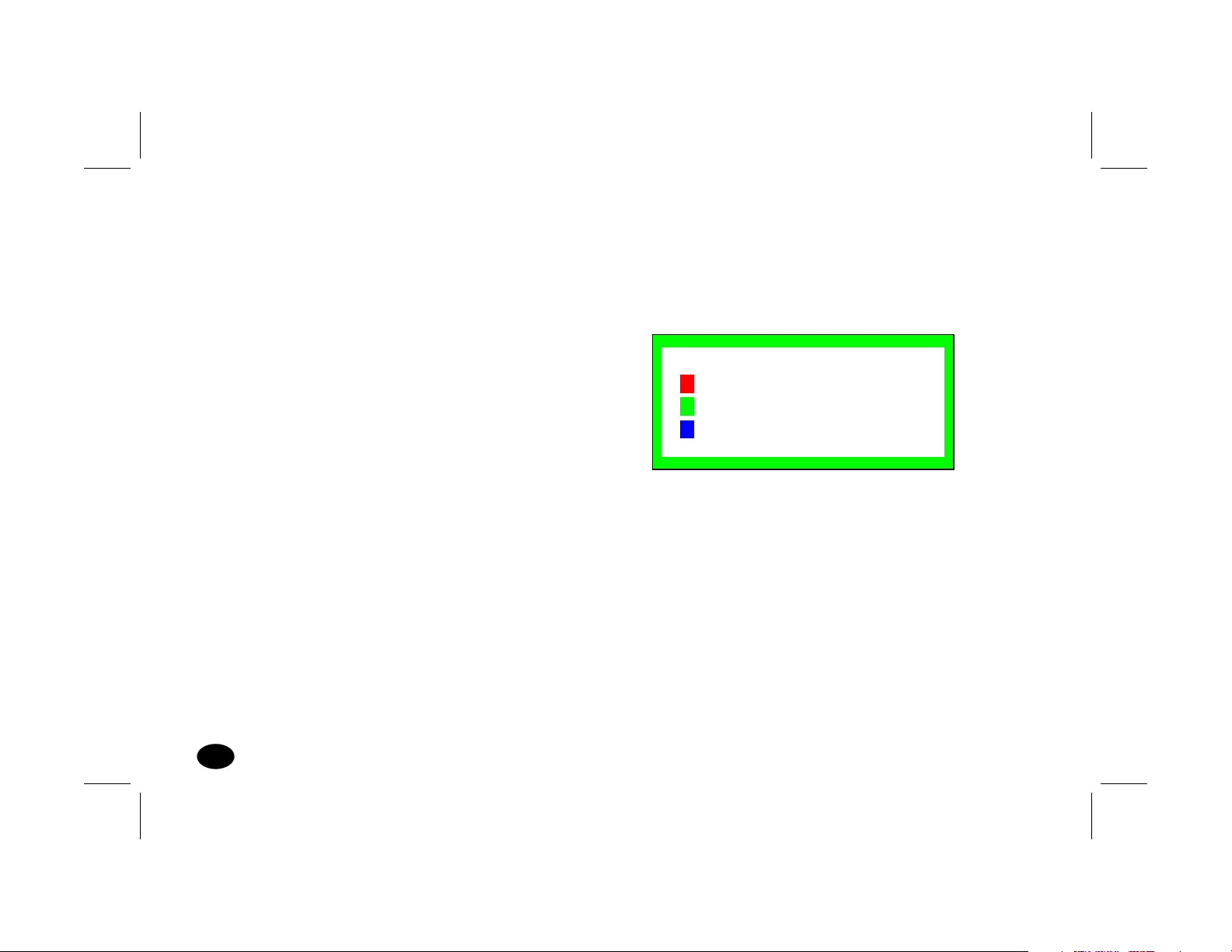
Self-test–When you disconnect the signal cable
from the PC, the display will produce as below:
SELF-TEST PATTERN
NO SIGNAL
PLEASE CHECK
SIGNAL CABLE
8
Color temperature selection–9300K / 6550K /
user adjustable.
4
S70 Monitor Guide
Filename: S70naug.doc Title: S70 Monitor
Template: HP-Print.dot Author: WASSER, Inc. Last Saved By: WASSER, Inc.
Revision #: 6 Page: 4 of 28 Printed: 05/13/99 11:33 AM
Page 8

Specifications
Power Source
Power
Consumption
Picture Tube
Maximum
Resolution
AC 100—240V, 50/60Hz
(Full Range)
Normal: 100W Max.
1
Stand-by Mode: <15W
2
Suspend Mode: <15W
3
Off Mode: <5W
4
90° deflection,
0.27mm dot pitch
15.9" Diagonal (viewable)
low radiation, nonglare
Antistatic. Light
transmission 53%, MPR II
1280 x 1024 at 60Hz
refresh rate
Input Signals
Video Analog 0.7 Vp-p /
75 ohm positive
Separate Sync positive / negative
Synchronization
Horizontal 30KHz to 70KHz
Vertical 50Hz to 120Hz
Active Display
Area
Horizontal 306mm typical
Vertical 230mm typical
Safety Standard UL / CSA / TÜV
EMI Standard FCC Class B, EN50082-1,
EN55022
Filename: S70naug.doc Title: S70 Monitor
Template: HP-Print.dot Author: WASSER, Inc. Last Saved By: WASSER, Inc.
Revision #: 6 Page: 5 of 28 Printed: 05/13/99 11:33 AM
Specifications
5
Page 9
Environmental
Conditions
Operating
Temperature
Operating
Humidity
0° ~ 40°
10% ~ 80%
(non-condensing)
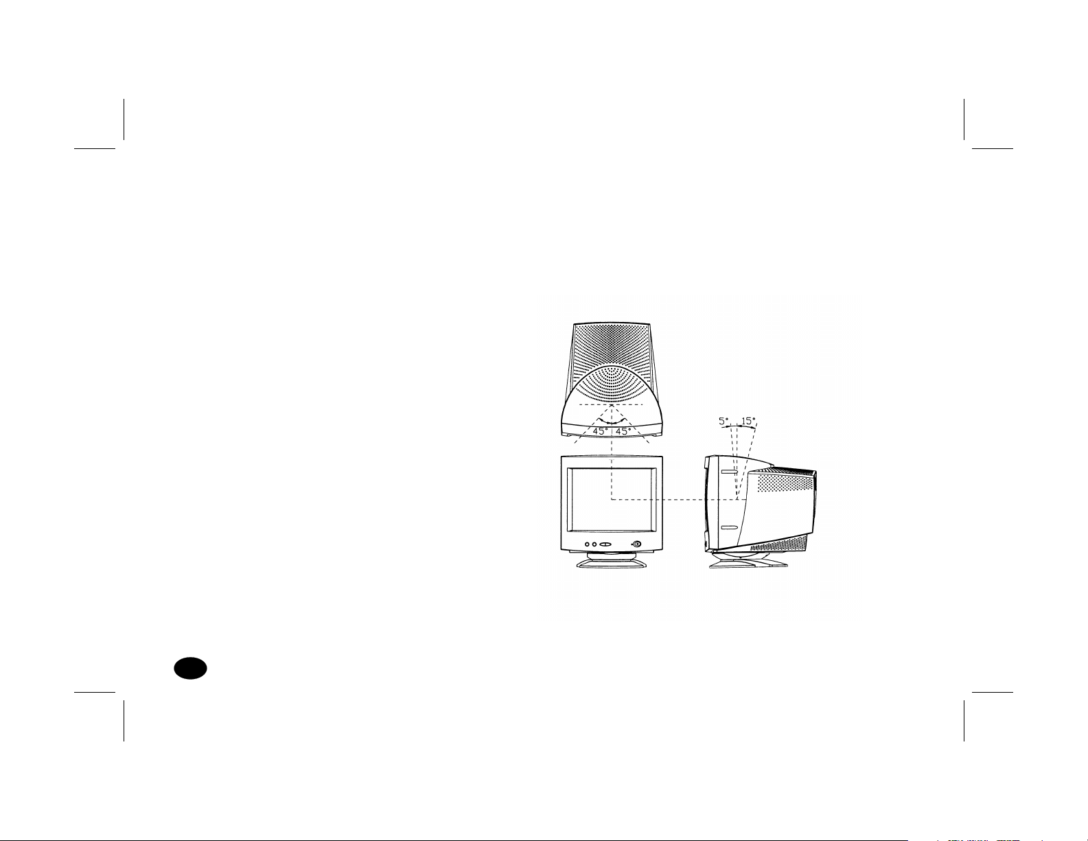
The tilt range is normally limited at an angle of
—5 degrees forwards and +15 degrees backwards.
This allows you to set the screen angle to the
viewing position most comfortable to you.
Storage
—40° ~ +65°
Temperature
Storage
5% ~ 95%
Humidity
High Voltage 26KV
Dimensions
(W x H x D)
416mm x 443mm x
455mm
Weight (Net) 17.1 kg
Tilt and Swivel Operation:
The swivel range is normally limited to 45 degrees
to the right and the left of the front position (marked
by a small molded pip on the top front of the base).
6
S70 Monitor Guide
Filename: S70naug.doc Title: S70 Monitor
Template: HP-Print.dot Author: WASSER, Inc. Last Saved By: WASSER, Inc.
Revision #: 6 Page: 6 of 28 Printed: 05/13/99 11:33 AM
Page 10
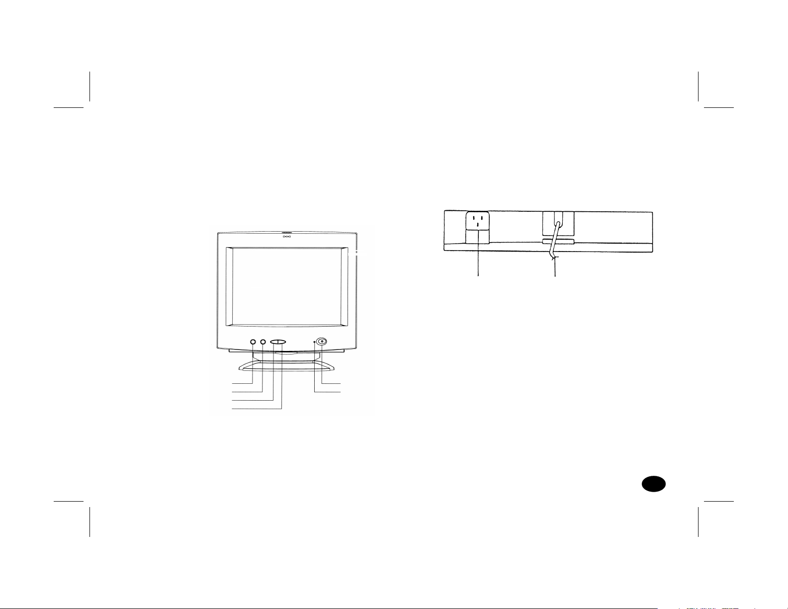
Control Locations and Functions
Note:
FRONT
Locations of display controls are shown below.
Operation of controls is explained in the following
pages.
Color
Select
-DOWN
+UP
POWER SWITCH
POWER INDICATOR
REAR
Power Supply Connector
Signal Cable
Filename: S70naug.doc Title: S70 Monitor
Template: HP-Print.dot Author: WASSER, Inc. Last Saved By: WASSER, Inc.
Revision #: 6 Page: 7 of 28 Printed: 05/13/99 11:33 AM
Control Locations and Functions
7
Page 11

Controls and Adjustments
V
%
Power LED
1
A.
This indicator will light when the power is ON
and the power cord is properly connected.
B. The state of the LED is dependent on the
Power state of the monitor. When the LED
is green, the monitor is in the normal state.
When it is amber, it indicates a power-saving
state.
Power Switch
2
A. Press to power on the monitor; press again to
power off.
B. We recommend to power your system on
first, then the monitor.
Geometric Adjust
3
A. Press the select key to display the
geometric adjustment menu.
B. Press the key again to select the function
to be adjusted; the selected Icon will change
in color from blue to red.
C. Use the UP or DOWN (À¿) keys to adjust
the setting of the selected function to the
desired level.
Geometric Adjustment Main Menu
Select
OSD
EXIT
RS
ertical Position 50
1024x768
OSD
S70 Monitor Guide
8
Filename: S70naug.doc Title: S70 Monitor
Template: HP-Print.dot Author: WASSER, Inc. Last Saved By: WASSER, Inc.
Revision #: 6 Page: 8 of 28 Printed: 05/13/99 11:33 AM
Page 12
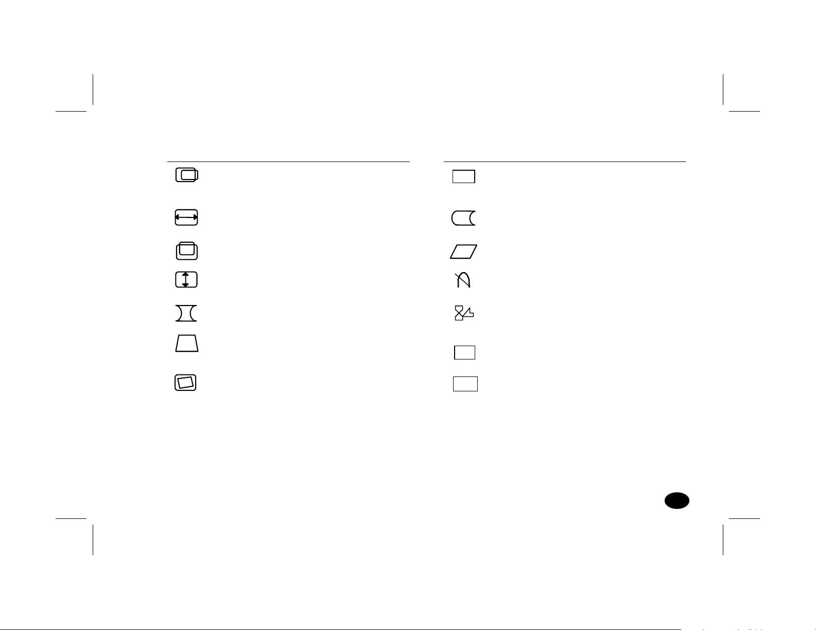
ICON NAME FUNCTION
ICON NAME FUNCTION
Horizontal
position
To adjust the
horizontal position
of the display
Horizontal size
To adjust the width of
the display
Vertical position
To adjust the vertical
position of the display
Vertical size To adjust the height of
the display
Pincushion To adjust any tapering
or bowing of the sides
Trapezoid To adjust the top and
bottom of the image to
the same size
Rotation
To adjust the
display tilt
OSD
RS
EXIT
OSD horizontal
position
To enable the OSD
menu to be moved
horizontally
Side Pin Balance To straighten the left or
right side of the image
Parallelogram To square the
image
Degauss To degauss the
display
OSD display
time
To set “on screen display”
time to either 10, 20 or
30 seconds.
Recall
To recall the original
factory display settings
Exit To remove the OSD
menu
Filename: S70naug.doc Title: S70 Monitor
Template: HP-Print.dot Author: WASSER, Inc. Last Saved By: WASSER, Inc.
Revision #: 6 Page: 9 of 28 Printed: 05/13/99 11:33 AM
Controls and Adjustments
9
Page 13
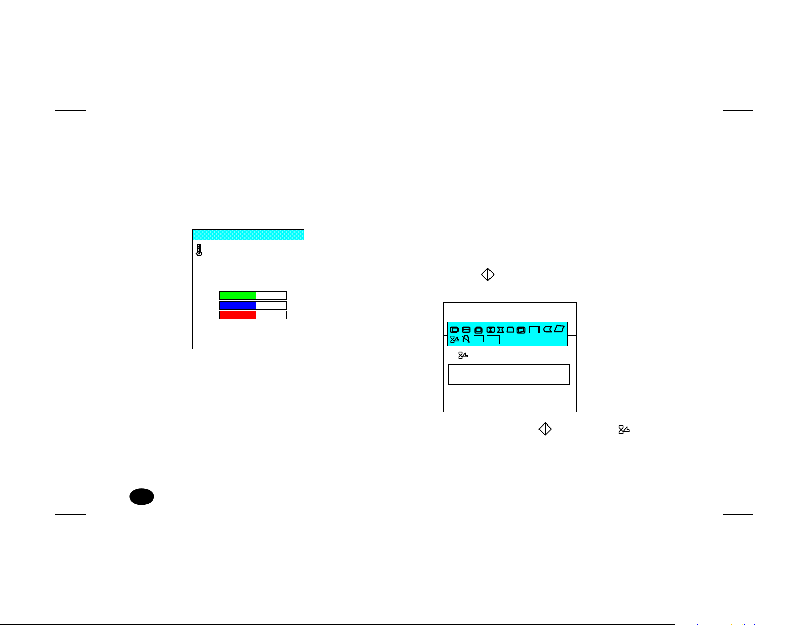
Color Temperature Adjustment
4
A.
Press the COLOR key to display the color
temperature control menu.
Color Temperature Adjustment Menu
Color select
9300°K
6500°K
User color
EXIT
GB-
-
COLOR OK
+ Enter
B. Press the COLOR key to move to your
desired color or to EXIT. To select a color or
to exit, press the UP or DOWN key when the
selection is highlighted (blue background).
C. When the “USER COLOR” is selected,
press the COLOR key to move between
the colors. Press the UP or DOWN key to
change color settings, or to exit the “USER
COLOR” mode when the “COLOR OK” is
highlighted.
OSD Display Time Adjustment
5
A. Press the key to display the geometric
adjustment menu.
Select
RS
E
EXIT
OSD DISPLAY TIME
10 20 30 SECONDS
1024 x 768
H:69KHz V:85Hz
OSD
B. Continue to press the key until the
function is selected and 10 20 30 seconds
appears in the OSD as above.
10
S70 Monitor Guide
Filename: S70naug.doc Title: S70 Monitor
Template: HP-Print.dot Author: WASSER, Inc. Last Saved By: WASSER, Inc.
Revision #: 6 Page: 10 of 28 Printed: 05/13/99 11:33 AM
Page 14

C. Press either the UP or DOWN (À¿) key to
select the required time; the selected time
will change in color from white to yellow.
D. Following completion of any readjustments,
the OSD will remain on the screen for the
selected period of time before disappearing
automatically.
Degauss Control
6
B. Press the key again until the function
RS
is selected.
C. Press either the UP or DOWN (À¿) key; the
display will then return to the initial factory
settings.
Exit
8
A. Press the key to display the geometric
adjustment menu.
A. Press the key to display the geometric
adjustment menu.
B. Press the key to select the degauss icon .
C. Press either the UP or DOWN (À¿) key; the
degauss function will then automatically
occur.
Recall Control (to recall original factory
7
settings)
A. Press the key to display the geometric
adjustment menu.
Filename: S70naug.doc Title: S70 Monitor
Template: HP-Print.dot Author: WASSER, Inc. Last Saved By: WASSER, Inc.
Revision #: 6 Page: 11 of 28 Printed: 05/13/99 11:33 AM
B. Press the key again until the function
EXIT
is selected.
C. Press either the UP or DOWN (À¿) key; the
OSD menu will immediately disappear.
D. If the Exit function is not used the OSD menu
will automatically disappear after the timing
period has expired.
Controls and Adjustments
11
Page 15

Connections
Your monitor has two connecting cables: a Power
Supply Cord, which connects to a wall outlet, surge
protector or other power source, and a Signal Cable,
which connects to the graphics adapter of your
computer. To ensure safety and correct operation,
always follow these four steps when connecting the
monitor:
1
Make sure the monitor and computer are turned
off. (See previous section on safety.)
2
Connect the power cord to the back of the
display.
3
Plug the other end of the cable into a grounded
outlet.
4
Connect the video cable on the monitor to the
15-pin video graphics connector on the rear
panel of the computer, and tighten the fastening
screws.
(If you have an HP Pavilion computer, this port
is marked in orange. For other computers,
check your computer manual for the video
port location.)
Note:
Don’t force the cable into the connector; line it
up carefully so you don’t bend the pins.
12
S70 Monitor Guide
Filename: S70naug.doc Title: S70 Monitor
Template: HP-Print.dot Author: WASSER, Inc. Last Saved By: WASSER, Inc.
Revision #: 6 Page: 12 of 28 Printed: 05/13/99 11:33 AM
Page 16

Connecting the Speakers
The display is designed for use with speakers
supplied with HP Pavilion computers.
To connect the speakers:
Identify the left and right speakers. You can tell
1
which side a speaker fits onto by its mounting
pegs. The side of the speaker with mounting
pegs fits against the side of the display.
Fit the pegs of the right speaker into the
2
corresponding holes on the right side of the
display, then push down until the speaker is
secure.
Fit the pegs of the left speaker into the
3
corresponding holes on the left side of the
display, then push down until the speaker is
secure.
To make mounting easier, angle the speaker slightly
toward the center of the display, then insert the pegs.
Refer to your computer setup poster for instructions
to connect your speakers to the PC.
Filename: S70naug.doc Title: S70 Monitor
Template: HP-Print.dot Author: WASSER, Inc. Last Saved By: WASSER, Inc.
Revision #: 6 Page: 13 of 28 Printed: 05/13/99 11:33 AM
Connections
13
Page 17

Pin Assignments and Signal Levels
15-Pin D-SUB male video connector
1
6
11
PIN NO. SIGNAL PIN NO. SIGNAL
1 RED 9 +5V FROM PC
2 GREEN 10 DIGITAL GROUND
3 BLUE 11 MONITOR SENSE1
4 DIGITAL GROUND 12 SDA (DDC1/2B)
5 RETURN (DDC2B) 13 H. SYNC.
6 GROUND 14 V. SYNC.
7 GROUND 15 SCL (DDC2B)
8GROUND
SIGNAL LEVEL
Note:
The signal level at pin 1,2,3 is 0.7 Vp-p.
The signal level at pin 13,14 is 5 Vp-p.
14
S70 Monitor Guide
Filename: S70naug.doc Title: S70 Monitor
Template: HP-Print.dot Author: WASSER, Inc. Last Saved By: WASSER, Inc.
Revision #: 6 Page: 14 of 28 Printed: 05/13/99 11:33 AM
Page 18

Timing Charts
V
V
V
SEPARATE SYNC.
HORIZONTAL
Hor. Video
Hor. Sync.
ERTICAL
ert. Video
ert. Sync.
Timing Charts
Filename: S70naug.doc Title: S70 Monitor
Template: HP-Print.dot Author: WASSER, Inc. Last Saved By: WASSER, Inc.
Revision #: 6 Page: 15 of 28 Printed: 05/13/99 11:33 AM
15
Page 19

FACTORY MODES
Mode No. 1 2 3 4 5 Unit
Resolution 640 x 480 720 x 400 640 x 480 800 x 600 640 x 480
Horizontal Frequency 31.468 31.468 37.500 37.878 43.269 KHz
(A) Horizontal 31.778 31.778 26.667 26.4 23.1 usec
(B) Horizontal Pulse Width 3.813 3.813 2.032 3.2 1.556 usec
(C) Horizontal Back Porch 1.907 1.907 3.810 2.2 2.222 usec
(D) Horizontal Active Area 25.422 25.422 20.318 20.0 17.778 usec
(E) Horizontal Front Porch 0.636 0.636 0.18 1.0 1.556 usec
(F) H. Sync. Polarity — — — + —
Vertical Frequency 59.943 70.000 75.000 60.31 85.0 Hz
(O) Vertical Period 16.683 14.268 13.333 16.579 11.764 msec
(P) Vertical Pulse Width 0.064 0.064 0.08 0.1056 0.069 msec
(Q) Vertical Back Porch 1.049 1.112 0.427 0.607 0.578 msec
(R) Vertical Active Area 15.253 12.711 12.800 15.84 11.093 msec
(S) Vertical Front Porch 0.318 0.381 0.027 0.0264 0.023 msec
(T) V. Sync. Polarity — + — + —
(U) Interlaced No No No No No
16
S70 Monitor Guide
Filename: S70naug.doc Title: S70 Monitor
Template: HP-Print.dot Author: WASSER, Inc. Last Saved By: WASSER, Inc.
Revision #: 6 Page: 16 of 28 Printed: 05/13/99 11:33 AM
Page 20

FACTORY MODES
Mode No. 6 7 8 9 10 Unit
Resolution 800 x 600 1024 x 768 800 x 600 1024 x 768 1024 x 768
Horizontal Frequency 46.875 48.363 53.674 68.667 56.476 KHz
(A) Horizontal 21.333 20.677 18.631 14.561 17.707 usec
(B) Horizontal Pulse Width 1.616 2.092 1.138 1.013 1.813 usec
(C) Horizontal Back Porch 3.232 2.462 2.702 2.2 1.92 usec
(D) Horizontal Active Area 16.162 15.754 14.222 10.836 13.653 usec
(E) Horizontal Front Porch 0.323 0.369 0.702 0.471 0.521 usec
(F) H. Sync. Polarity + — + + —
Vertical Frequency 75.000 60.004 85.061 85 70.069 Hz
(O) Vertical Period 13.333 16.666 11.756 11.764 14.272 msec
(P) Vertical Pulse Width 0.064 0.124 0.056 0.044 0.106 msec
(Q) Vertical Back Porch 0.448 0.600 0.503 0.524 0.513 msec
(R) Vertical Active Area 12.800 15.88 11.179 11.182 13.599 msec
(S) Vertical Front Porch 0.021 0.062 0.019 0.014 0.054 msec
(T) V. Sync. Polarity + — + + —
(U) Interlaced No No No No No
Filename: S70naug.doc Title: S70 Monitor
Template: HP-Print.dot Author: WASSER, Inc. Last Saved By: WASSER, Inc.
Revision #: 6 Page: 17 of 28 Printed: 05/13/99 11:33 AM
Timing Charts
17
Page 21

Troubleshooting
Before you call an authorized service center, please
check if the following items are properly connected.
If a nonstandard personal computer or graphics
PROBLEM CHECKS LOCATION
No Picture or
POWER indicator off.
No picture, POWER indicator off,
AC cord plugged in, POWER switch on.
Image is not centered.
No picture, POWER indicator on.
* AC cord plugged in
* POWER switch on
* Signal cable connected
* Turn off POWER switch, wait at
least 30 seconds, turn it back on.
* V-CENTERING Control
* H-PHASE Control
* CONTRAST Control
* BRIGHTNESS Control
adapter is being used, make sure the pin assignments
of the signal input connector and the signal timing
meet the specifications detailed previously.
Rear
Front
Rear
Front
Front
Front
Front
Front
18
S70 Monitor Guide
Filename: S70naug.doc Title: S70 Monitor
Template: HP-Print.dot Author: WASSER, Inc. Last Saved By: WASSER, Inc.
Revision #: 6 Page: 18 of 28 Printed: 05/13/99 11:33 AM
Page 22

A
utomatic Power Saving
Introduction
“Green Concept” has prevailed throughout
the information market of the world for some
years. EPA (Environmental Protection Agency)
stipulates that all information products sold to
the UNITED STATES should meet the requirement
of environmental protection. Thus, we promote
a series of monitors with power-saving features
which meet the “EPA” energy star requirement.
Below are the criteria:
When either horizontal or vertical sync is absent,
the monitor will automatically enter the
“Suspend” or “Stand-by” state and the power
LED color will be yellow.
When the PC recovers from the sleep state by
either operation of the keyboard or mouse, the
monitor will power up normally and the power
LED will be green.
Power Consumption
Features
When the monitor is connected to an unpowered
PC or when both horizontal and vertical syncs
are not present, the monitor will enter the
“off” state and the power LED will be amber.
Filename: S70naug.doc Title: S70 Monitor
Template: HP-Print.dot Author: WASSER, Inc. Last Saved By: WASSER, Inc.
Revision #: 6 Page: 19 of 28 Printed: 05/13/99 11:33 AM
The monitor power is reduced to less than 5 Watts
in the power save “OFF” state and meets the U.S.A
“EPA” energy star requirement and VESA “DPMS”
requirement.
Automatic Power Saving
19
Page 23

Federal Communications Commission Notice
This equipment has been tested and found to comply with the
limits for a Class B digital device pursuant to Part 15 of the
FCC Rules. These limits are designed to provide reasonable
protection against harmful interference in a residential
installation. This equipment generates, uses, and can
radiate radio frequency energy and, if not installed and
used in accordance with the instructions, may cause harmful
interference to radio communications. However, there is
no guarantee that interference will not occur in a particular
installation. If this equipment does cause harmful interference
to radio or television reception, which can be determined by
turning the equipment off and on, the user is encouraged
to try to correct the interference by one or more of the
following measures:
Reorient or relocate the receiving antenna.
Increase the separation between the equipment and the
receiver.
Connect the equipment into an outlet on a circuit different
from that to which the receiver is connected.
Consult the dealer or an experienced radio or television
technician for help.
X-Ray Radiation Notice
When operating, this product emits X-rays; however, it is well
shielded and meets the safety and health requirements of
various countries, such as the Radiation Act of Germany
and the Radiation Control for Health and Safety Act of the
United States.
Radiation emitted by this product is less than 0.1mR/hr
(1PSv/hr) at a distance of 10 centimeters from the surface of
the cathode-ray tube. The x-ray radiation primarily depends
on the characteristics of the cathode-ray tube and its associated
low-voltage and high-voltage circuitry. Internal controls
have been adjusted to ensure safe operation. Only qualified
personnel should perform any internal adjustments, as
specified in the service manual for this product.
Replace the cathode-ray tube with an identical CRT only.
Cables
Connections to this device must be made with shielded cables
with metallic REI/EMI connector hoods to maintain compliance
with FCC Rules and Regulations.
Canadian Notice
This Class B digital apparatus meets all requirements of the
Canadian Interference — Causing Equipment Regulations.
20
Filename: S70naug.doc Title: S70 Monitor
Template: HP-Print.dot Author: WASSER, Inc. Last Saved By: WASSER, Inc.
Revision #: 6 Page: 20 of 28 Printed: 05/13/99 11:33 AM
S70 Monitor Guide
Page 24

Avis Canadien
Cet appareil numérique de la classe B respecte toutes les
exigences du Réglement sur le matériel brouilleur du Canada.
EPA Energy Star
Monitors that are marked with the Energy Star logo meet the
requirements of the EPA Energy Star program. Specific details
on using the Energy Star features can be found in the energy
saver or power management section of the manual that comes
with the computer the monitor is connected to.
Product names mentioned herein may be trademarks and/or
registered trademarks of their respective companies.
Copyright © 1999 Hewlett-Packard Company.
All rights reserved.
Produced in Taiwan
Filename: S70naug.doc Title: S70 Monitor
Template: HP-Print.dot Author: WASSER, Inc. Last Saved By: WASSER, Inc.
Revision #: 6 Page: 21 of 28 Printed: 05/13/99 11:33 AM
Automatic Power Saving
21
Page 25

Filename: S70naug.doc Title: S70 Monitor
Template: HP-Print.dot Author: WASSER, Inc. Last Saved By: WASSER, Inc.
Revision #: 6 Page: 22 of 28 Printed: 05/13/99 11:33 AM
Page 26

Filename: S70naug.doc Title: S70 Monitor
Template: HP-Print.dot Author: WASSER, Inc. Last Saved By: WASSER, Inc.
Revision #: 6 Page: 23 of 28 Printed: 05/13/99 11:33 AM
Page 27

Filename: S70naug.doc Title: S70 Monitor
Template: HP-Print.dot Author: WASSER, Inc. Last Saved By: WASSER, Inc.
Revision #: 6 Page: 24 of 28 Printed: 05/13/99 11:33 AM
 Loading...