

Page 1

Administrator’s Guide for Microsoft Windows
on HP ProLiant Blade Workstations
January 2009
Part number: 443069-004
Fourth edition: January 2009
Page 2

2
© Copyright 2009 Hewlett-Packard Development Company, L.P.
The information contained herein is subject to change without notice. The only warranties for HP products and services are set forth in the
express warranty statements accompanying such products and services. Nothing herein should be construed as constituting an additional
warranty. HP shall not be liable for technical or editorial errors or omissions contained herein.
Windows and Windows Server are registered trademarks of Microsoft Corporation in the United States and other countries.
Intel and Xeon are trademarks of Intel Corporation in the United States and other countries.
Part number: 443069-004
Fourth edition: January 2009
Audience Assumptions
This guide is for the person who installs, administers, and troubleshoots blade workstations and client access
devices. HP assumes you are qualified in the servicing of computer equipment and trained in recognizing
hazards in products with hazardous energy levels and are familiar with weight and stability precautions for rack
installations.
Page 3

Contents 3
Contents
1 Introduction
1-1 Nomenclature...................................................................................................................... 8
1-2 Administrator’s Guide organization ...................................................................................... 10
1-3 Blade workstation solution documents ................................................................................... 11
1-4 Obtaining HP technical support ........................................................................................... 12
1-5 Customer Self Repair .......................................................................................................... 12
1-6 Ordering Windows recovery media ..................................................................................... 12
1-7 Microsoft Windows licensing............................................................................................... 12
2 Blade workstation video subsystem
2-1 Setting Remote Console Mode ............................................................................................. 16
2-2 Admin Mode ..................................................................................................................... 17
2-3 Setup Mode ......................................................................................................................18
2-4 User Mode........................................................................................................................ 19
2-5 Summary of Remote Console Modes..................................................................................... 20
3 Installing, powering on, booting, and validating the blade workstation solution
3-1 Setting up the client computer .............................................................................................. 22
3-2 Installing and turning on the blade workstation ...................................................................... 22
3-2-1 Preparing the blade workstation infrastructure........................................................................ 22
3-2-2 Configuring the blade workstation hardware ......................................................................... 23
3-2-3 Connecting media to the blade workstation ........................................................................... 24
3-2-4 Powering on the blade workstation....................................................................................... 25
3-2-5 Blade workstation sleep states.............................................................................................. 26
3-3 The OOBE screens ............................................................................................................. 26
3-4 Verifying networking .......................................................................................................... 27
3-4-1 NIC1 and NIC2 verification ................................................................................................ 27
3-4-2 iLO 2 network verification ................................................................................................... 28
3-5 Installing, configuring, and verifying RGS.............................................................................. 29
3-5-1 Installing RGS.................................................................................................................... 29
3-5-2 Setting the RGS NIC binding order....................................................................................... 29
3-5-3 Setting User Mode ............................................................................................................. 31
3-5-4 Verifying RGS operation ..................................................................................................... 31
3-6 Installing applications .........................................................................................................31
3-7 Validating the solution ........................................................................................................ 32
3-8 Integrate additional blade workstations and client computers................................................... 32
3-9 Optional: Configure network teaming ................................................................................... 32
4 Creating a custom Windows XP-32 image
4-1 Components in the factory-installed Windows XP-32 image ..................................................... 34
4-2 Creating a custom Windows XP-32 image............................................................................. 35
4-2-1 Required components ......................................................................................................... 35
4-2-2 Optional software components............................................................................................. 36
4-2-3 Creating the Windows XP-32 image..................................................................................... 36
4-2-4 Configuring the operating system ......................................................................................... 45
4-2-5 Verifying the network connections ........................................................................................ 47
4-2-6 Installing and verifying RGS ................................................................................................ 47
4-2-7 Installing the applications .................................................................................................... 47
4-2-8 Validating the solution ........................................................................................................ 47
4-2-9 Deploying the Windows image............................................................................................ 47
5 Restoring Windows XP-32
5-1-1 Hardware configuration...................................................................................................... 48
5-1-2 Restoring Windows XP-32 from the RestorePlus! CD................................................................ 48
6 Using Windows XP-64 on the blade workstation
Page 4

Contents 4
6-1 Windows XP-64 processes .................................................................................................. 49
7 Using Windows Vista on the blade workstation
7-1 Acquiring Windows Vista ................................................................................................... 50
7-2 Installing Windows Vista..................................................................................................... 50
7-2-1 Hardware configuration...................................................................................................... 50
7-2-2 Windows Vista installation steps .......................................................................................... 51
7-3 Viewing the Windows Vista desktop..................................................................................... 51
8 Capturing a blade workstation image using HP RDP
9 Deploying a blade workstation image using HP RDP
10 Performing an unattended installation of Windows XP-32 and Windows XP-64
10-1 Assumptions ...................................................................................................................... 58
10-2 Unattended installation procedure ........................................................................................ 59
11 User Information
11-1 Introduction ....................................................................................................................... 68
11-2 Powering on the HP blade workstation client.......................................................................... 68
11-3 Changing the behavior of RGS ............................................................................................ 68
11-4 Connecting from the client to the blade ................................................................................. 69
11-4-1 Using Enterprise Directory ......................................................................................... 69
11-4-2 Using a local directory file......................................................................................... 70
11-4-3 Using manual entry................................................................................................... 70
11-5 Sending Ctrl+Alt+Delete to the blade workstation................................................................... 71
11-6 Accessing blade workstation desktop windows ...................................................................... 71
11-7 Moving desktop windows between monitors.......................................................................... 72
11-8 Spanning multiple displays with a desktop window ................................................................ 72
11-9 Maximizing a window to a single display ............................................................................. 72
11-10 Supported USB devices....................................................................................................... 73
11-11 Synchronizing a PDA.......................................................................................................... 73
11-12 Adjusting audio volume on the client and blade ..................................................................... 73
11-13 Disconnecting the client from the blade workstations............................................................... 74
11-14 Reconnecting to disconnected sessions.................................................................................. 74
12 Managing the blade workstation
12-1 Onboard Administrator....................................................................................................... 76
12-2 Integrated Lights-Out 2 (iLO 2) ............................................................................................. 78
12-2-1 Accessing iLO 2....................................................................................................... 78
12-2-2 iLO 2 Remote Console .............................................................................................. 79
12-2-3 Viewing the Windows desktop................................................................................... 81
12-2-4 iLO 2 virtual media................................................................................................... 82
12-3 Remote Desktop Connection ................................................................................................ 84
12-4 System Management Homepage.......................................................................................... 86
12-4-1 Local access to SMH................................................................................................. 87
12-5 HP Systems Insight Manager................................................................................................ 87
12-6 HP Rapid Deployment Pack ................................................................................................. 88
12-6-1 Introduction ............................................................................................................. 88
12-6-2 HP RDP content ........................................................................................................ 88
12-6-3 Infrastructure requirements ......................................................................................... 88
12-6-4 HP RDP-specific differences between server blades and blade workstations...................... 88
12-6-5 Use Rip-n-Replace and Virtual Bay features to replace failed systems ............................... 89
12-7 HP Insight Diagnostics ........................................................................................................ 90
12-7-1 Key features and benefits .......................................................................................... 90
12-7-2 Theory of operation .................................................................................................. 90
12-7-3 Accessing HP Insight Diagnostics................................................................................ 90
12-7-4 Survey tab............................................................................................................... 91
12-7-5 Test tab................................................................................................................... 91
12-7-6 Status tab................................................................................................................ 92
Page 5

Contents 5
12-7-7 Log tab ................................................................................................................... 92
12-7-8 Help tab.................................................................................................................. 92
12-7-9 Saving and printing information in HP Insight Diagnostics.............................................. 92
12-7-10 Downloading the latest version of HP Insight Diagnostics ............................................... 93
12-8 ROM-Based Setup Utility ..................................................................................................... 93
12-9 Power-on Self Test ..............................................................................................................93
12-10 BIOS Serial Console........................................................................................................... 93
12-11 BIOS programming ............................................................................................................ 93
13 Troubleshooting the blade workstation solution
13-1 Troubleshooting SMH problems ........................................................................................... 94
13-2 Troubleshooting HP SIM problems ........................................................................................ 94
13-3 Troubleshooting RGS problems ............................................................................................ 95
13-4 Troubleshooting Windows problems..................................................................................... 96
APPENDIX A: Downloading and installing SoftPaqs and Smart Components
A-1 Downloading and installing SoftPaqs.................................................................................................. 97
A-2 Downloading and installing Smart Components .................................................................................101
A-2-1 Installing Smart Components using their graphical user interface .................................................. 101
A-2-2 Command line installation of Smart Components ........................................................................ 103
Index
Page 6

Figures 6
Figures
Figure 1-1 Simplified HP Blade Workstation Solution documentation hierarchy .................................................. 11
Figure 2-1 Video subsystem architecture and operating modes ........................................................................ 14
Figure 2-2 Viewing and setting Remote Console Mode ................................................................................... 16
Figure 2-3 Admin Mode ............................................................................................................................. 17
Figure 2-4 Setup Mode............................................................................................................................... 18
Figure 2-5 User Mode ................................................................................................................................ 19
Figure 3-1 The HP Graphics Expansion Blade attaches to the xw460c blade workstation .................................... 23
Figure 3-2 Connecting media to the blade workstation ................................................................................... 24
Figure 3-3 Connecting a monitor, keyboard, and mouse to the blade workstation .............................................. 25
Figure 3-4 The OOBE Administrator password screen..................................................................................... 26
Figure 3-5 System Management Homepage .................................................................................................. 27
Figure 3-6 Boot console display of the iLO 2 IP address .................................................................................. 28
Figure 3-7 iLO 2 login screen ...................................................................................................................... 28
Figure 3-8 Viewing the two blade workstation NICs ....................................................................................... 29
Figure 3-9 NIC IP addresses........................................................................................................................ 30
Figure 3-10 Determining the first NIC .......................................................................................................... 30
Figure 3-11 Advanced Settings dialog.......................................................................................................... 30
Figure 4-1 Windows setup screen ................................................................................................................ 36
Figure 4-2 Mass storage setup screen........................................................................................................... 37
Figure 4-3 Storage driver prompt screen ....................................................................................................... 37
Figure 4-4 SCSI adapter selection screen ...................................................................................................... 38
Figure 4-5 Windows XP Pro setup screen ...................................................................................................... 38
Figure 4-6 Windows XP EULA ..................................................................................................................... 39
Figure 4-7 Windows setup manual installation screen..................................................................................... 40
Figure 4-8 Windows logo testing screen ....................................................................................................... 40
Figure 4-9 Product key screen..................................................................................................................... 41
Figure 4-10 Computer Name and Administrator Password screen ....................................................................42
Figure 4-11 Installation of SNMP ................................................................................................................. 43
Figure 4-12 SNMP service properties ........................................................................................................... 44
Figure 8-1 Process to capture the blade workstation OS image ........................................................................ 52
Figure 9-1 Process to deploy an OS image to the blade workstation................................................................. 55
Figure 10-1 Example unattended installation directories.................................................................................. 59
Figure 10-2 SoftPaq that provides support files for unattended installation of Windows ....................................... 60
Figure 11-1 RGS Receiver Single Sign-on authentication prompt ...................................................................... 69
Figure 11-2 Blade Easy Login screen ............................................................................................................ 70
Figure 11-3 Rebooting Windows on the blade................................................................................................ 74
Figure 12-1 Enclosure front and rear views ................................................................................................... 76
Figure 12-2 Detailed blade information ........................................................................................................ 77
Figure 12-3 Blade power management......................................................................................................... 77
Figure 12-4 iLO 2 status summary................................................................................................................ 78
Figure 12-5 Remote Console selection .......................................................................................................... 79
Figure 12-6 Boot console ............................................................................................................................ 80
Figure 12-7 Windows desktop..................................................................................................................... 81
Figure 12-8 The Ctrl+Alt+Del button ............................................................................................................. 81
Figure 12-9 Connecting virtual media........................................................................................................... 82
Figure 12-10 PC files accessible from the blade workstation Windows desktop ................................................. 83
Figure 12-11 Mounting of virtual media to the blade workstation using the Integrated Remote Console ................. 83
Figure 12-12 Remote Desktop Connection menu ............................................................................................ 84
Figure 12-13 Blade IP address..................................................................................................................... 84
Figure 12-14 RDC Windows desktop ........................................................................................................... 85
Figure 12-15 SMH login screen ................................................................................................................... 86
Figure 12-16 System status page ................................................................................................................. 86
Figure 12-17 Accessing SMH from the Start Menu ......................................................................................... 87
Figure A-1 Operating system selection options............................................................................................... 98
Page 7

Tables 7
Figure A-2 Broadcom network driver SoftPaq................................................................................................. 98
Figure A-3 SoftPaq file download window..................................................................................................... 99
Figure A-4 Softpaq startup window .............................................................................................................. 99
Figure A-5 Specifying the unpacking location of the SoftPaq files ................................................................... 100
Figure A-6 Unpacked SoftPaq files ............................................................................................................. 100
Figure A-7 Downloading and initiating installation of Smart Components ........................................................ 101
Figure A-8 Initial Smart Component installation GUI ..................................................................................... 102
Figure A-9 Pre-installation window ............................................................................................................. 102
Tables
Table 1-1 Windows-related procedures described in this document .................................................................... 8
Table 2-1 Use of the video controllers in Admin Mode.................................................................................... 17
Table 2-2 Use of the video controllers in Setup Mode ..................................................................................... 18
Table 2-3 Use of the video controllers in User Mode....................................................................................... 19
Table 2-4 Use of the video controllers for each Remote Console Mode.............................................................. 20
Table 4-1 HP System Management Homepage port exceptions ........................................................................45
Table 4-2 RGS Sender port exception........................................................................................................... 45
Table 4-3 HP RDP port exceptions ................................................................................................................ 46
Table 10-1 Example drivers and software ..................................................................................................... 60
Table 10-2 RGS and utilities........................................................................................................................ 61
Table 13-1 Troubleshooting System Management Homepage problems ............................................................ 94
Table 13-2 Troubleshooting HP Systems Insight Manager problems .................................................................. 94
Table 13-3 Troubleshooting RGS problems.................................................................................................... 95
Table 13-4 Troubleshooting Windows problems ............................................................................................ 96
Page 8

Introduction 8
1 Introduction
For an overview of the HP Blade Workstation Solution, including its architecture, HP recommends that you read
the following document—it is the Read-Me-First document for the HP Blade Workstation Solution:
HP Blade Workstation Solution Planning Guide
This document is available at www.hp.com/support/xw460c_manuals and
www.hp.com/support/xw2x220c_manuals. Also available on these websites is the document:
Hardware and Software Supported by HP ProLiant Blade Workstations
The above document describes the latest hardware and software supported by the blade workstations. See
Section 1-3, “Blade workstation solution documents,“ for additional blade workstation solution documentation.
This Administrator’s Guide provides the information shown in Table 1-1 for Microsoft® Windows® XP Pro SP2,
Microsoft Windows XP Pro x64 Edition and Windows Vista (both 32-bit and 64-bit versions). All seven of the
procedures in Table 1-1 are supported on Windows XP Pro SP2 and SP3, while, for Windows XP Pro x64 and
Windows Vista, a subset of the seven procedures is supported. Click on the links in the table for detailed
information.
Table 1-1 Windows-related procedures described in this document
1-1 Nomenclature
For simplicity, the following nomenclature, shown in bold, is used to reference each Windows operating system:
1. Microsoft Windows XP
• Microsoft Windows XP Professional SP2 and SP3—Windows XP-32
• Microsoft Windows XP Professional x64 Edition—Windows XP-64
2. Windows Vista
• Genuine Windows Vista Business Blade PC Edition, 32-bit version—Windows Vista-32
• Genuine Windows Vista Business Blade PC Edition, 64-bit version—Windows Vista-64
IMPORTANT: Windows Vista-32 and Windows Vista-64 recovery media (DVDs) are available to allow you to begin
evaluating Windows Vista in your blade workstation environment. Prior to installing Windows Vista-32 or Windows
Vista-64, it is important to understand that the RGS Sender is not yet supported on Windows Vista—see Chapter 7,
“Using Windows Vista on the blade workstation
,” for further details.
Windows-related Procedures
OS
Bringing up
the blade
workstation
with the
factory-
installed OS
Installing
and verifying
RGS
Creating
and
configuring
a custom
OS
Restoring
the OS
Capturing
an
OS image
using RDP
Deploying
an OS
image
using RDP
Unattended
installation
Windows
XP Pro SP2
and SP3
Chapter 3 Chapter 4 Chapter 5
Windows
XP Pro x64
Edition
Section 3-5
Chapter 6
Chapter 8
Chapter 9 Chapter 10
Windows
Vista (32-bit
and 64-bit)
Not applicable—
these operating
systems cannot
currently be
ordered factory-
installed
The RGS Sender
is not currently
supported on
Windows Vista
Chapter 7
Page 9

Introduction 9
NOTE: References to “Windows XP” or “Windows Vista” without a numeric suffix apply to both the 32-bit and 64-bit
versions of the operating system.
The following nomenclature, shown in bold, is used to reference each blade workstation:
1. HP ProLiant xw460c Blade Workstation—xw460c blade workstation
2. HP ProLiant xw2x220c Blade Workstation—xw2x220c blade workstation
The phrase “blade workstation” refers to either the xw460c blade workstation or the xw2x220c blade
workstation.
Page 10

Introduction 10
1-2 Administrator’s Guide organization
This document is organized as follows:
Chapter 1—Introduction
This chapter describes where to find the blade workstation solution documentation, and how to obtain HP
technical support. The chapter also describes Windows licensing on blade workstations.
Chapter 2—Blade workstation video subsystem
This chapter describes the blade workstation video subsystem, covering the two video controllers. This
chapter also describes how to select which video controller is active, and how to view the image generated
by the video controllers.
Chapter 3—Installing, powering on, booting, and validating the blade workstation solution
This chapter describes how to prepare the blade workstation solution, including the blade workstation, the
enclosure, the network, the client computer, and HP Remote Graphics Software.
Chapter 4—Creating a custom Windows XP-32 image
This chapter describes how to create a custom Windows XP-32 image for the blade workstation.
Chapter 5—Restoring Windows XP-32
This chapter describes how to restore the factory-installed Windows XP-32 operating system.
Chapter 6—Using Windows XP-64 on the blade workstation
This chapter describes the key differences in how Windows XP-64 is used on the blade workstation
compared to Windows XP-32.
Chapter 7—Using Windows Vista on the blade workstation
This chapter describes Windows Vista-32 and Windows Vista-64 on the blade workstation.
Chapter 8—Capturing a blade workstation image using HP RDP
This chapter describes how to capture a blade workstation image on Windows XP-32 and Windows XP-64
using HP Rapid Deployment Pack.
Chapter 9—Deploying a blade workstation image using HP RDP
This chapter describes how to deploy a blade workstation image on Windows XP-32 and Windows XP-64
using HP Rapid Deployment Pack.
Chapter 10—Performing an unattended installation of Windows XP-32 and Windows XP-64
This chapter describes how to perform an unattended installation of Windows XP-32 and Windows XP-64.
Chapter 11—User Information
This chapter provides information to guide the end-users of the HP Blade Workstation Solution.
Chapter 12—Managing the blade workstation
This chapter describes the management features of the blade workstation, such as Integrated Lights-Out 2
(iLO 2), Onboard Administrator, and System Management Homepage.
Chapter 13—Troubleshooting the blade workstation solution
This chapter describes possible problems with your blade workstation solution, as well as likely causes and
troubleshooting suggestions.
Appendix A—Downloading and installing SoftPaqs and Smart Components
This appendix describes how to find, download, and install blade workstation SoftPaqs and Smart
Components, covering both Windows XP-32 and Windows XP-64.
Page 11
Introduction 11
1-3 Blade workstation solution documents
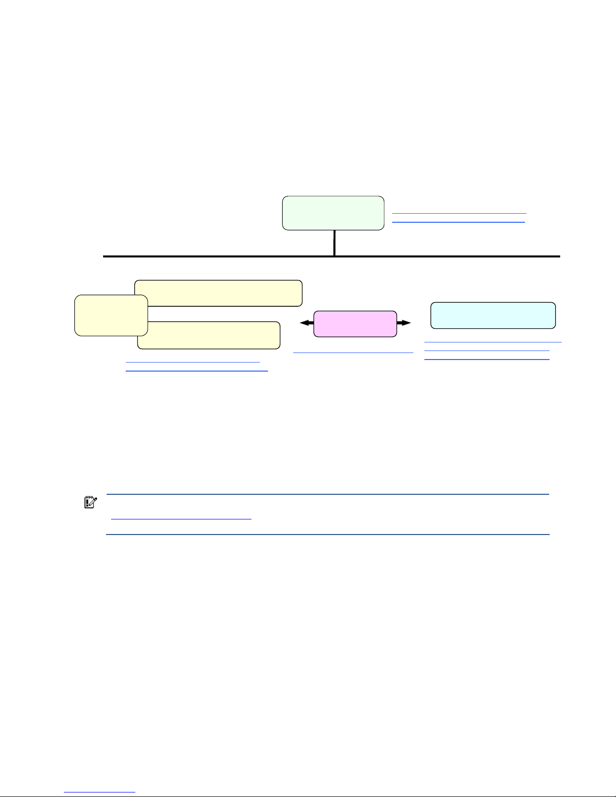
Figure 1-1 provides a simplified documentation hierarchy of the HP Blade Workstation Solution. The HP Blade
Workstation Solution Planning Guide is the top-most document in the documentation hierarchy, and, as noted
previously, is the recommended document to begin with. At the next level in the hierarchy are the documents
describing the following three building blocks of the blade workstation solution:
1. HP ProLiant Blade Workstations
2. HP Remote Graphics Software (HP RGS)
3. Client computers
Figure 1-1 Simplified HP Blade Workstation Solution documentation hierarchy
As shown in Figure 1-1, two Administrator’s Guides are available for the HP ProLiant Blade Workstations:
• Administrator’s Guide for Microsoft Windows on HP ProLiant Blade Workstations (this document)
• Administrator’s Guide for Linux on HP ProLiant Blade Workstations
Accompanying these Administrator’s Guides is the document Hardware and Software Supported by HP ProLiant
Blade Workstations. This document lists hardware that works with the blade workstation, such as network
switches and graphics cards. The document also lists software, such as manageability software, that is supported
by the blade workstation.
IMPORTANT: Windows Vista-32 recovery DVDs are shipped with the blade workstation. See Section 1-6,
“Ordering Windows recovery media,” for information on ordering Windows XP-32 and Windows Vista-64
recovery media.
The primary Remote Graphics Software document is the HP Remote Graphics Software User Guide. The client
computers are described in the HP Blade Workstation Client series – Embedded OS Version 9.xx manual. These
documents, and many others, are available on the websites listed in Figure 1-1. Please visit these websites to
view all blade workstation solution documents.
HP Remote Graphics
Software User Guide
HP Blade Workstation
Solution Planning Guide
Administrator’s Guide for Microsoft Windows
on HP ProLiant Blade Workstations
Administrator’s Guide for Linux
on HP ProLiant Blade Workstations
HP Blade Workstation Client series -Embedded OS Version 9.xx
HP ProLiant Blade Workstations
HP RGS
client computers
www.hp.com/support/rgs_manuals
www.hp.com/support/bwclient_manuals
www.hp.com/support/dc72_manuals
www.hp.com/support/dc73_manuals
www.hp.com/support/xw460c_manuals,
www.hp.com/support/xw2x220c_manu
als
This
document
Hardware and
Software Supported
by HP ProLiant
Blade Workstations
www.hp.com/support/xw460c_manuals,
www.hp.com/support/xw2x220c_manuals
Page 12

Introduction 12
1-4 Obtaining HP technical support
If you encounter an issue that requires technical support, please do the following prior to contacting HP for
assistance:
• Be near your blade workstation
• Have available your blade workstation serial number, product number, and model name
• Note the following:
• Error messages
• Add-on options
• Operating system
• Third-party hardware or software
• Blinking LEDs on the blade workstation
• Applications you were using when you encountered the issue
• Be prepared to spend the time necessary to troubleshoot the problem with support personnel
To find your HP support center phone number, visit the HP website at
welcome.hp.com/country/us/en/wwcontact_us.html
. Select your region, and click the Technical support after
you buy link under the Call HP heading to obtain the support center phone number for your region.
In North America, call 800-HP Invent (800-474-6836). As of the date this document was published, providing
the following voice responses will connect you to the appropriate support personnel:
1. “technical support”
2. “software”
3. “workstation”
4. “blade workstation”
You’ll be asked for your blade workstation model number and serial number.
1-5 Customer Self Repair
HP ProLiant Blade Workstations are designed with many Customer Self Repair parts to minimize repair time, and
allow for greater flexibility in replacing defective parts. For information on Customer Self Repair for your blade
workstation, please see the following documents:
HP ProLiant xw460c Blade Workstation Maintenance and Service Guide at www.hp.com/support/xw460c_manuals
HP ProLiant xw2x220c Blade Workstation Maintenance and Service Guide at www.hp.com/support/xw2x220c_manuals
1-6 Ordering Windows recovery media
Recovery media is available for the following operating systems:
• Windows XP-32
• Windows Vista-32 (recovery media for Windows Vista-32 is included with your blade workstation)
• Windows Vista-64
To order recovery media in North America, call the HP Order Center at 800-952-7689 (US) or 800-567-1616
(Canada). Outside of North America, call your HP support center as described in Section 1-4.
1-7 Microsoft Windows licensing
The HP ProLiant Blade Workstations include a license for Microsoft Windows Vista Business Blade PC Edition.
The functionality of the Blade PC Edition is identical to the respective standard OS version but differs in the
licensing terms.
For example, the Blade PC Edition is licensed only for blade workstations, not conventional desktop systems.
However, Microsoft Volume License customers can use their XP Professional or Vista Business or Enterprise
Volume License bits on blade workstations because the binary code is the same as the respective Blade PC
Edition.
Page 13

Introduction 13
Another difference between the Blade PC Editions and the standard Microsoft Windows OS versions is that the
Blade PC Editions includes a single Remote Desktop License (RDL). Ensure that you review and adhere to the RDL.
For more information, refer to the Microsoft Windows XP Professional Blade PC Edition End User License
Agreement (EULA) or the Windows Vista Business Blade PC Edition Licensing Terms, as appropriate. Contact
legal counsel to determine your rights and responsibilities under this license.
Blade workstations purchased with the Genuine Windows Vista® downgrade to Genuine Microsoft® Windows®
XP Professional option include a license for Microsoft Windows Vista™ Business Blade PC Edition. The Vista OS
installed on the system disk has been downgraded in the factory to Microsoft Windows XP Professional Blade PC
Edition in accordance with your rights under the Microsoft License Terms for Microsoft Windows Vista™ Business
Blade PC Edition. The Blade PC Editions of both operating systems are identical to the usual corresponding
Business/Professional OS, but differ in their licensing terms.
Page 14
Blade workstation video subsystem 14
2 Blade workstation video subsystem
This chapter describes the blade workstation video subsystem. Because the blade workstation contains two types
of video controllers, it is important to understand their functionality and operating modes. The two types of video
controllers are:
• ATI RN50 video controller (“ATI video controller”)—The ATI Video controller is built-into the blade
workstation.
• NVIDIA Quadro FX graphics adapter (“NVIDIA graphics adapter”)—The xw460c blade workstation
supports a number of NVIDIA graphics adapters, either in single-card configurations or dual-card
configurations. See the document Hardware and Software Supported by HP ProLiant Blade Workstations
for a description of the NVIDIA graphics adapters supported by the xw460c blade workstation, as well as
whether they are supported in single-card or dual-card configurations.
The xw2x220c blade workstation supports only a single type of NVIDIA graphics adapter; again, see the
document Hardware and Software Supported by HP ProLiant Blade Workstations for a description of the
NVIDIA graphics adapter supported by the xw2x220c blade workstation
In September 2008, HP began offering the HP Graphics Expansion Blade (“expansion blade”), which attaches to
the xw460c blade workstation only. The expansion blade supports the installation of certain PCI-Express NVIDIA
Quadro FX graphics adapters. Again, see Hardware and Software Supported by HP ProLiant Blade Workstations
for a description of the PCI-Express NVIDIA graphics adapters that can be installed in the expansion blade (as
well as the NVIDIA graphics adapters that can be installed internal to the blade workstation). Note that the
expansion blade does not currently support dual graphics—that is, only one PCI-Express graphics adapter can be
installed in the expansion blade.
NOTE: NVIDIA graphics adapters are installed internal to the xw460c blade workstation if an expansion
blade is not attached to the blade workstation. If an expansion blade is attached, graphics adapters can only
be installed in the expansion blade, not internal to the blade workstation. Unless otherwise noted, no
distinction is made in this chapter based on where the graphics adapter(s) are installed—internal to the
xw460c blade workstation or in the expansion blade—because their installation location is invisible to
Windows.
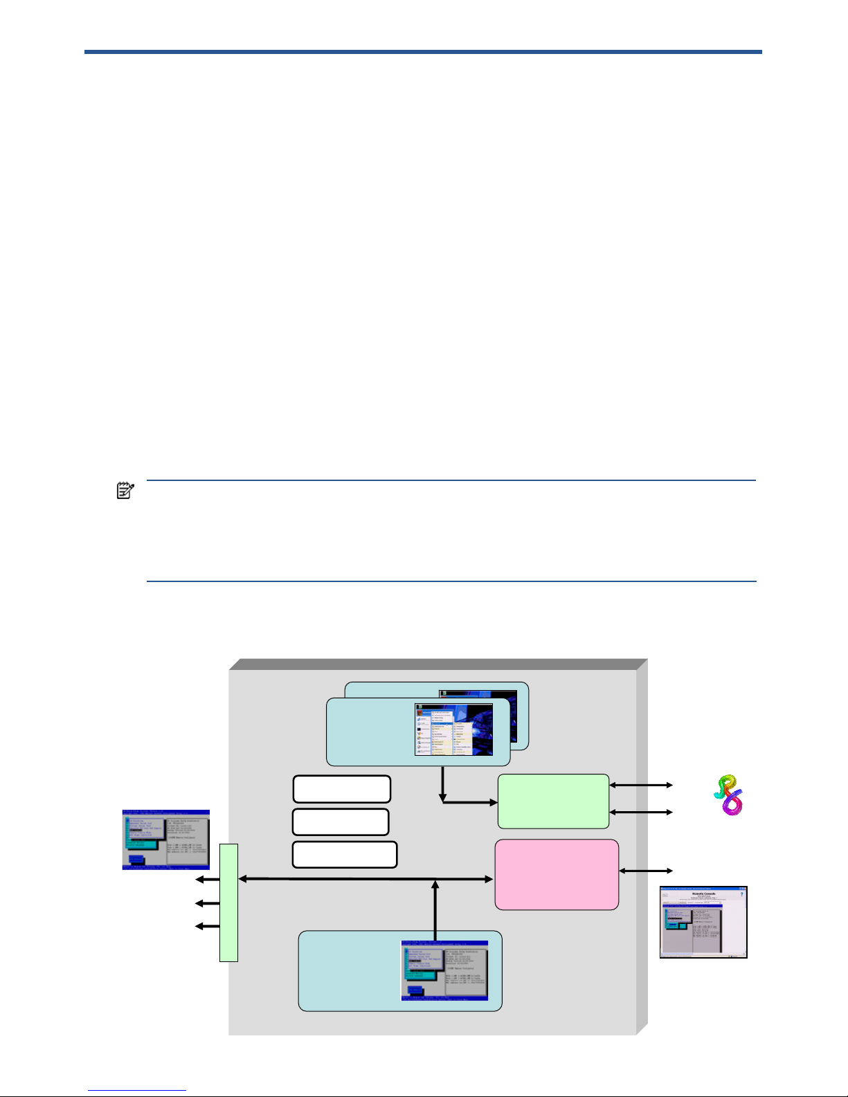
Figure 2-1 shows the blade workstation video subsystem architecture, and lists the three operating modes.
Figure 2-1 Video subsystem architecture and operating modes
Dual Broadcom
5708s Ethernet
controllers
iLO 2
management
processor
ATI RN50
video controller
(1280 x 1024)
NIC 1
NIC 2
iLO 2
Admin Mode
User Mode
Setup Mode
video
USB x 2
serial
Local I/O Connector
NVIDIA Quadro
FX graphics
adapter
NVIDIA Quadro
FX graphics
adapter
Boot console
Windows desktop
in Admin Mode
and Setup Mode
Windows desktop
in User Mode
One or two
graphics
adapters
Page 15

Blade workstation video subsystem 15
The key features of the video subsystem are:
• The blade workstation boot console is always generated by the ATI video controller. The boot console can
be viewed either by connecting a monitor to the video output of the Local I/O Connector, or can be viewed
over the network using the iLO 2 Ethernet port, as shown in Figure 2-1.
• The Windows desktop typically runs on the NVIDIA graphics adapter.
• Viewing of the Windows desktop on internally-installed NVIDIA graphics adapter(s) is performed using
RGS—there is no video connector on the blade workstation to allow direct viewing of the video from
NVIDIA graphics adapter(s) installed internal to the blade workstation.
• Operation of the blade workstation ATI video controller and NVIDIA graphics adapter is governed by the
BIOS parameter Remote Console Mode, which can be set to the following three modes:
1. Admin Mode
2. User Mode (default setting)
3. Setup Mode
The following sections describe how to set Remote Console Mode, and how the setting affects display of the
Windows desktop.
NOTE: Remote Console Mode is different than the iLO 2 Remote Console. Remote Console Mode is a BIOS
setting while iLO 2 Remote Console is a means of viewing blade operation through the iLO 2 network port.
Page 16
Blade workstation video subsystem 16
2-1 Setting Remote Console Mode
Remote Console Mode can be viewed or changed during the Power-On Self Test (POST) phase. During POST,
the boot console is generated by the ATI video controller in all three Remote Console Modes, as shown in Figure
2-1. To view or set Remote Console Mode during booting, perform the following steps:
1. Establish a means of viewing the boot console using either the Local I/O Connector or the iLO 2 Ethernet
port. Using iLO 2 is typically more convenient than using the Local I/O Connector, and also provides direct
control of the blade workstation power.
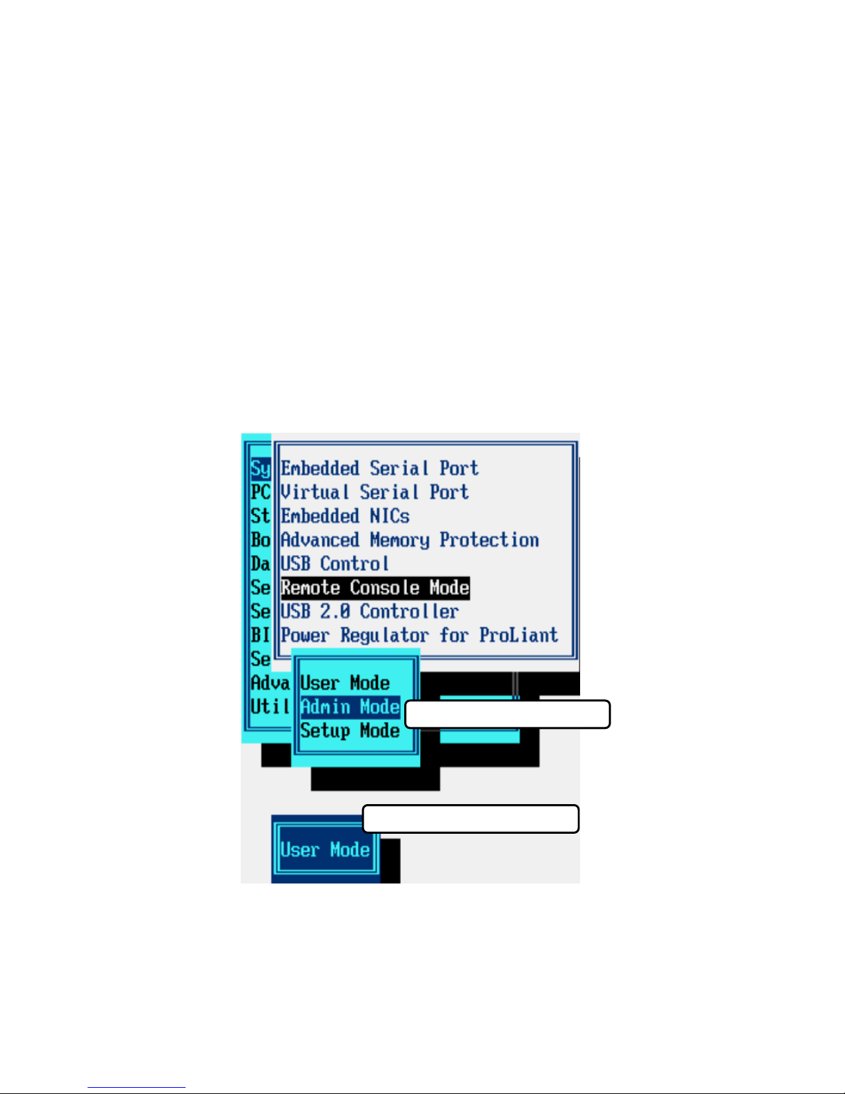
2. Initiate a restart of the blade workstation. Press the F9 key on your keyboard when prompted during
booting. This will bring up the ROM-based Setup Utility (see Figure 2-2).
3. Select System Options -> Remote Console Mode, which will display the current Remote Console Mode. In
Figure 2-2, the current Remote Console Mode is User Mode.
4. To change the Remote Console Mode, press Enter to bring up the Remote Console Mode menu, and then
use your Up and Down arrow keys to select the desired mode. In Figure 2-2, Admin Mode has been
selected. Press Enter when done, and perform the steps indicated to exit the ROM-based Setup Utility.
5. The blade workstation will automatically perform a reboot, and will come up in the Remote Console Mode
that you selected.
Figure 2-2 Viewing and setting Remote Console Mode
Current Remote Console Mode
Remote Console Mode menu
Page 17
Blade workstation video subsystem 17
2-2 Admin Mode
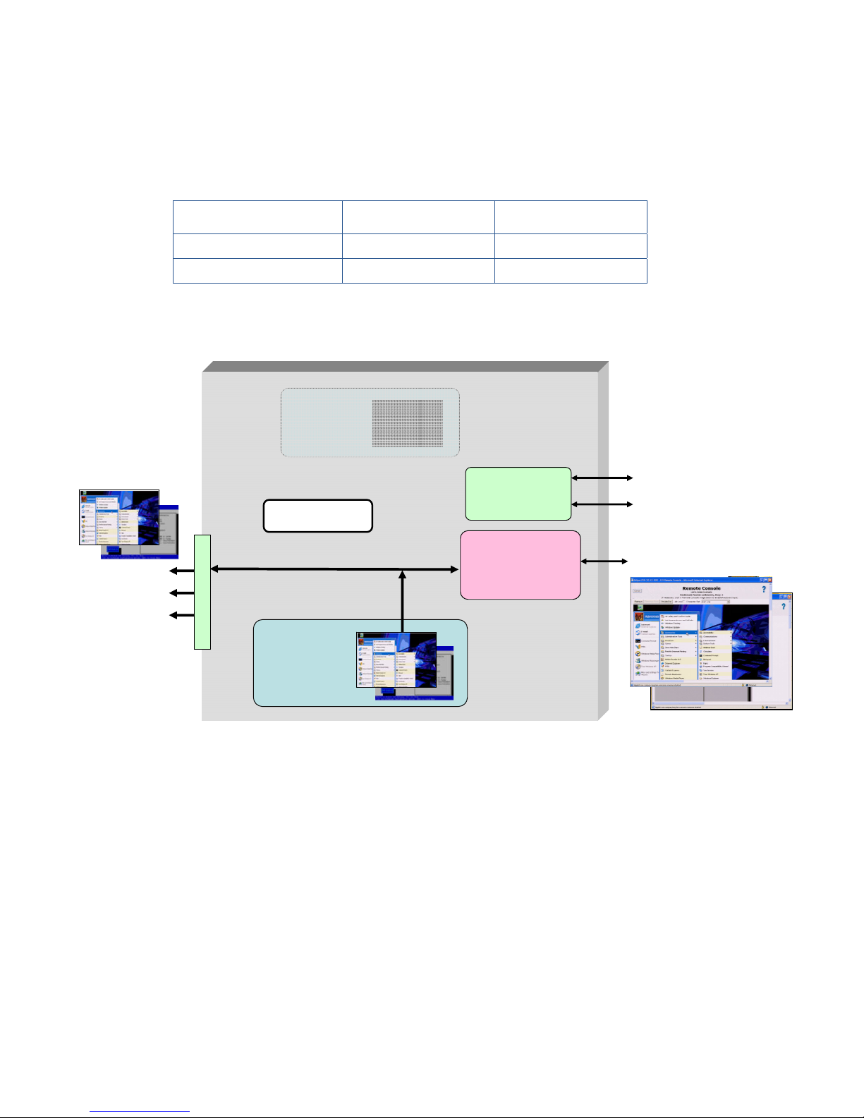
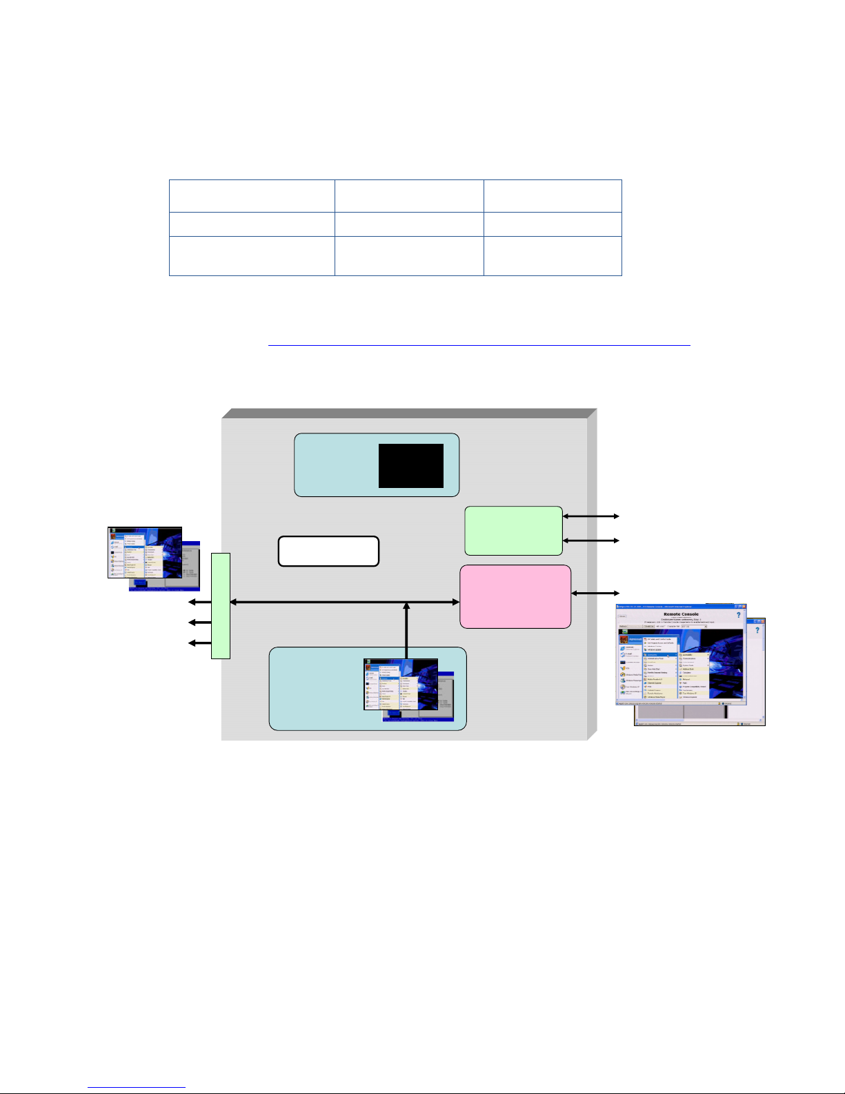
When Remote Console Mode is set to Admin Mode, the ATI video controller first generates the boot console
during Power-on Self Test (POST), and then generates the Windows desktop (see Table 2-1 and Figure 2-3). In
this mode, the NVIDIA graphics adapter is not visible to Windows, and is not used.
Table 2-1 Use of the video controllers in Admin Mode
Usage during POST Usage after booting
ATI video controller Boot console Windows desktop
NVIDIA graphics adapter Not used Invisible to Windows
Figure 2-3 Admin Mode
In Admin Mode, the boot console and the Windows desktop generated by the ATI video controller can be
viewed in two ways:
• Using a monitor connected to the Local I/O Connector video signal
• Using the iLO 2 Remote Console by pointing your browser to the iLO 2 IP address
NVIDIA Quadro
FX graphics
adapter
Dual Broadcom
5708 Ethernet
controllers
iLO 2
management
processor
ATI RN50
video controller
(1280 x 1024)
NIC 1
NIC 2
iLO 2
First the boot console
and then the Windows
desktop are generated
by the ATI video
controller
NVIDIA graphics
adapter is not visible
to Windows
Admin Mode
video
USB x 2
serial
Local I/O Connector
Windows desktop
Boot console
Windows desktop
Boot console
Page 18
Blade workstation video subsystem 18
2-3 Setup Mode
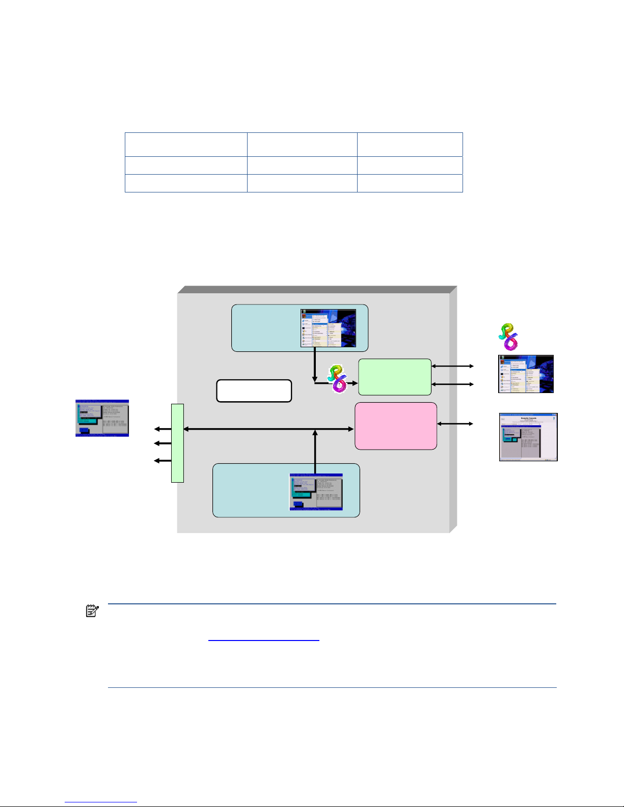
Setup Mode is very similar to Admin Mode—the ATI video controller first generates the boot console and then
generates the Windows desktop (see Table 2-2 and Figure 2-4). In Setup Mode, however, the NVIDIA graphics
adapter, although it isn’t used, is visible to Windows.
Table 2-2 Use of the video controllers in Setup Mode
Usage during POST Usage after booting
ATI video controller Boot console Windows desktop
NVIDIA graphics adapter Not used
Not used but is
visible to Windows
Visibility of the NVIDIA graphics adapter allows the Windows operating system to install the NVIDIA graphics
adapter driver the first time the blade workstation boots. For more information about the initial blade workstation
boot, see Chapter 3, “Installing, powering on, booting, and validating the blade workstation solution.”
Figure 2-4 Setup Mode
In Setup Mode, as with Admin Mode, the Windows desktop can be viewed in two ways:
• Using a monitor connected to the Local I/O Connector video signal
• Using the iLO 2 Remote Console by pointing your browser to the iLO 2 IP address
NVIDIA Quadro
FX graphics
adapter
Dual Broadcom
5708 Ethernet
controllers
iLO 2
management
processor
ATI RN50
video controller
(1280 x 1024)
NIC 1
NIC 2
iLO 2
NVIDIA graphics
adapter is visible
to the operating
system
Setup Mode
video
USB x 2
serial
Local I/O Connector
Windows desktop
Boot console
First the boot console
and then the Windows
desktop are generated
by the ATI video
controller
Windows desktop
Boot console
Page 19
Blade workstation video subsystem 19
2-4 User Mode
When Remote Console Mode is set to User Mode, the boot console is, as usual, generated by the ATI video
controller. Following the booting of Windows, the NVIDIA graphics adapter generates the Windows desktop
(see Table 2-3 and Figure 2-5).
Table 2-3 Use of the video controllers in User Mode
Usage during POST Usage after booting
ATI video controller Boot console Not used
NVIDIA graphics adapter Note used Windows desktop
In User Mode, the Windows desktop can only be viewed using RGS through NIC1 or NIC2. Because the ATI
video controller is inactive after Windows starts, the Windows desktop is not viewable on the Local I/O
Connector or through iLO 2.
Figure 2-5 User Mode
As noted previously, the default setting of Remote Console Mode is User Mode. This enables custom Windows
images (loaded through processes such as PXE booting) to boot directly into User Mode without needing to
change Remote Console Mode from its default setting.
NOTE: In addition to viewing the Windows desktop generated by one of the video controllers, the Windows
desktop can also be viewed using Microsoft Remote Desktop Connection (RDC). For more information about
RDC, see Section 12-3, “Remote Desktop Connection
.”
These viewing methods cannot be used simultaneously. If RDC is started, the Windows desktop session
provided by the video controller is terminated and returns to a Windows login screen. If the user logs into
Windows while RDC is active, the RDC connection is terminated.
Dual Broadcom
5708 Ethernet
controllers
iLO 2
management
processor
ATI RN50
video controller
(1280 x 1024)
NIC 1
NIC 2
iLO 2
NVIDIA Quadro
FX graphics
adapter
Windows
desktop
User Mode
The ATI video controller
is used during booting
but is not used after
Windows starts.
video
USB x 2
serial
Local I/O Connector
Page 20

Blade workstation video subsystem 20
2-5 Summary of Remote Console Modes
Table 2-4 summarizes the use of the video controllers in the three Remote Console Modes—Admin Mode, Setup
Mode, and User Mode. The video controller used during booting is highlighted in green, showing that the ATI
video controller is used in all three Remote Console Modes to display the boot console during Power-on Self Test
(POST). The video controller used for the Windows desktop is highlighted in blue, showing that the ATI video
controller is used in Admin and Setup Modes, while the NVIDIA graphics adapter is used in User Mode.
Table 2-4 Use of the video controllers for each Remote Console Mode
Remote Console
Mode
Video controller
Usage during POST Usage after booting
ATI video controller
Boot console Windows desktop
Admin Mode
NVIDIA graphics adapter
Not used Invisible to Windows
ATI video controller
Boot console Windows desktop
Setup Mode
NVIDIA graphics adapter
Not used
Not used but is visible to
Windows. This enables the
NVIDIA graphics driver to
be installed the first time
Windows boots.
ATI video controller
Boot console Not used
User Mode
NVIDIA graphics adapter
Note used
Windows desktop
Page 21

Installing, powering on, booting, and validating the blade workstation solution 21
3 Installing, powering on, booting, and validating the
blade workstation solution
This chapter describes the process to install, power on, boot and validate the HP Blade Workstation Solution. A
building block approach is followed, starting with a single blade workstation and a single client computer. After
validating their operation, other blade workstations and client computers can be integrated into the solution.
The seven steps of this approach are listed below. Note that Step 1 is independent of steps 2–4. You can
perform Step 1 first, or Steps 2-4 first.
1. Set up the client computer.
2. Install and power on the first blade workstation by performing these steps:
a. Prepare the blade enclosure & its networking infrastructure.
b. Configure the blade workstation hardware.
c. Install the blade workstation into the enclosure and boot Windows XP Professional.
3. Boot and configure the Windows XP-32 operating system
4. Verify network connections to the blade workstation Ethernet ports: NIC1, NIC2, and iLO 2.
5. Install RGS on the blade workstation, and verify RGS operation between the blade workstation and the
client computer.
6. Install the required applications on the blade workstation.
7. Validate the solution consisting of the blade workstation, its applications, RGS, and the client computer.
After validating the solution, you can integrate other blade workstations and client computers into the solution.
NOTE: In previous generations of blade workstations (such as the HP ProLiant xw25p Blade Workstation), it
was possible to power a blade workstation without installing it in an enclosure by using the HP Diagnostic
Station. However, the xw460c and xw2x220c blade workstations do not have such a diagnostic station—the
only way to power these blade workstations, and connect them to the network, is to install the blade
workstations and network interconnect devices in the c3000 or c7000 enclosure.
The installation, power on, and validation procedures are based on the following assumptions:
• You are using the factory-installed Windows XP-32 operating system. For more information about creating a
custom Windows XP image, see Chapter 4, “Creating and restoring the Windows XP operating system
.”
• A personal computer (PC) is available to verify network connectivity to the blade workstation and client
computer.
• You have access to the documentation listed in Section 1-3, “Blade workstation solution documentation
.”
• Power calculations have been performed to ensure there is sufficient power in the enclosure for the blades
and other equipment. For more information, see the HP website at
www.hp.com/go/bladesystem/powercalculator.
• Sufficient cooling is available for the c3000 or c7000 enclosure.
• You have characterized and designed your network infrastructure to accommodate the network
requirements of your blade workstations and client computers. The HP Blade Workstation Solution Planning
Guide referenced in Chapter 1 provides extensive information on optimizing your network.
Page 22

Installing, powering on, booting, and validating the blade workstation solution 22
3-1 Setting up the client computer
If you are using one of the client computers in the HP Blade Workstation Client series, refer to the documentation
specific to your client computer, as described in Section 1-3, “Blade workstation solution documents.” RGS is
factory-installed on these client computers. If another client computer will be used, ensure that RGS (specifically,
the RGS Receiver) is installed on the computer, and is properly configured to establish a connection to the blade
workstation.
3-2 Installing and turning on the blade workstation
For an overview of the installation and turn on process, refer to the HP ProLiant xw460c Blade Workstation
Installation Instructions or the HP ProLiant xw2x220c Blade Workstation Installation Instructions. Because the
blade workstation shares many components with the server blade, the following server blade documents should
be referenced for details on the installation and turn on process (taking into account the enclosure that you’re
using):
• HP BladeSystem c7000 Enclosure Setup and Installation Guide
• Power Supply Installation Instructions for HP BladeSystem c7000 Enclosures
• HP BladeSystem c3000 Enclosure Setup and Installation Guide
• HP BladeSystem c3000 Tower Enclosure Setup and Installation Guide
• HP ProLiant BL460c Server Blade User Guide
• HP ProLiant BL2x220c Server Blade User Guide
• HP BladeSystem Onboard Administrator User Guide
• Integrated Lights-Out 2 User Guide
In addition, refer to your network interconnect device documentation.
3-2-1 Preparing the blade workstation infrastructure
To prepare the blade workstation infrastructure (enclosure, power supplies, Onboard Administrator modules, and
networking), perform the following steps:
1. To set up the enclosure, including wiring the Power Distribution Units (PDUs), follow the instructions in the
HP BladeSystem c7000 Enclosure Setup and Installation Guide.
2. Install power supplies in the enclosure according to the HP BladeSystem power guidelines on the HP
website at www.hp.com/go/bladesystem/powercalculator
.
3. Install the Onboard Administrator modules. If you are using multiple c3000 or c7000 enclosures, connect
the Onboard Administrator module in each enclosure to the uplink/downlink Ethernet connectors in each
module.
4. Install your network devices in the enclosure, and connect them to your site network infrastructure. The
document Hardware and Software Supported by HP ProLiant Blade Workstations describes the c7000
enclosure interconnect bay mappings for the xw460c blade workstation and the xw2x220c blade
workstation.
5. Connect power to the enclosure and turn it on. When the enclosure is powered up for the first time, Insight
Display launches an installation wizard to guide you in the configuration process. Complete the
configuration process and verify there are no installation or configuration errors that appear on the Insight
Display.
6. Verify the Onboard Administrator module and network devices can be accessed over the network from the
PC.
After completing the preceding steps, you should have a suitable environment for installing and powering on
your blade workstations.
Page 23
Installing, powering on, booting, and validating the blade workstation solution 23
3-2-2 Configuring the blade workstation hardware
The blade workstation hardware listed below is configured before installing the blade in the enclosure. Unless
otherwise noted, the hardware listed below can be configured on both the xw460c and xw2x220c blade
workstations.
IMPORTANT: Refer to the document Hardware and Software Supported by HP ProLiant Blade Workstations for
more details on hardware configuration, as well as the latest information on supported hardware and software.
• Intel Xeon processors—The blade workstation supports either one or two Dual-Core or Quad-Core
processors, offering multiple frequencies of each processor type. In dual processor configurations, both
processors must have the same number of cores, and must operate at the same frequency. See the
document Hardware and Software Supported by HP ProLiant Blade Workstations for a description of the
processors that are available for each blade workstation.
• Memory—Up to eight memory DIMMs can be installed in the blade workstation, supporting up to 64 GB of
memory for the xw460c blade workstation and up to 32 GB for each workstation node with the xw2x220c
blade workstation. See the document Hardware and Software Supported by HP ProLiant Blade
Workstations for a description of per-OS memory limitations.
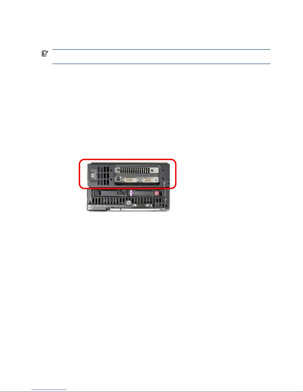
• HP Graphic Expansion Blade—The graphics expansion blade, circled in Figure 3-1, is supported as of
September 2008, on the xw460c blade workstation. The graphics expansion blade attaches to the top of
the blade workstation and accommodates a full length PCI-Express graphics card.
Figure 3-1 The HP Graphics Expansion Blade attaches to the xw460c blade workstation
The graphics expansion blade can only be purchased factory-attached to the blade workstation—it is not
currently available as a customer-installable option.
• NVIDIA Quadro FX graphics adapter—The xw460c blade workstation supports a number of graphics
adapters, which can be ordered factory-installed or as after market option kits. See the document Hardware
and Software Supported by HP ProLiant Blade Workstations for a list of the NVIDIA graphics adapters that
are available. The xw2x220c blade workstation supports only a single, factory-installed NVIDIA Quadro FX
770M graphics adapter per workstation node.
• Disk drives—The xw460c blade workstation supports one or two Serial Attached SCSI (SAS) disk drives,
with either 72 GB or 146 GB per drive. The xw2x220c blade workstation supports one 120 GB or one
250 GB SATA disk drive per workstation node.
• Storage controllers—The xw460c blade workstation can be ordered with either of these storage controllers:
• Storage controller with 64 MB of cache memory
• Storage controller with 128 MB of battery-backed write cache—This storage controller is the default
controller from the factory, and can also be ordered as a field upgrade.
The xw2x220c blade workstation is configured with one SATA storage controller per workstation node.
HP ProLiant xw460c
Blade Workstation
HP Graphics
Expansion Blade
Page 24
Installing, powering on, booting, and validating the blade workstation solution 24
3-2-3 Connecting media to the blade workstation
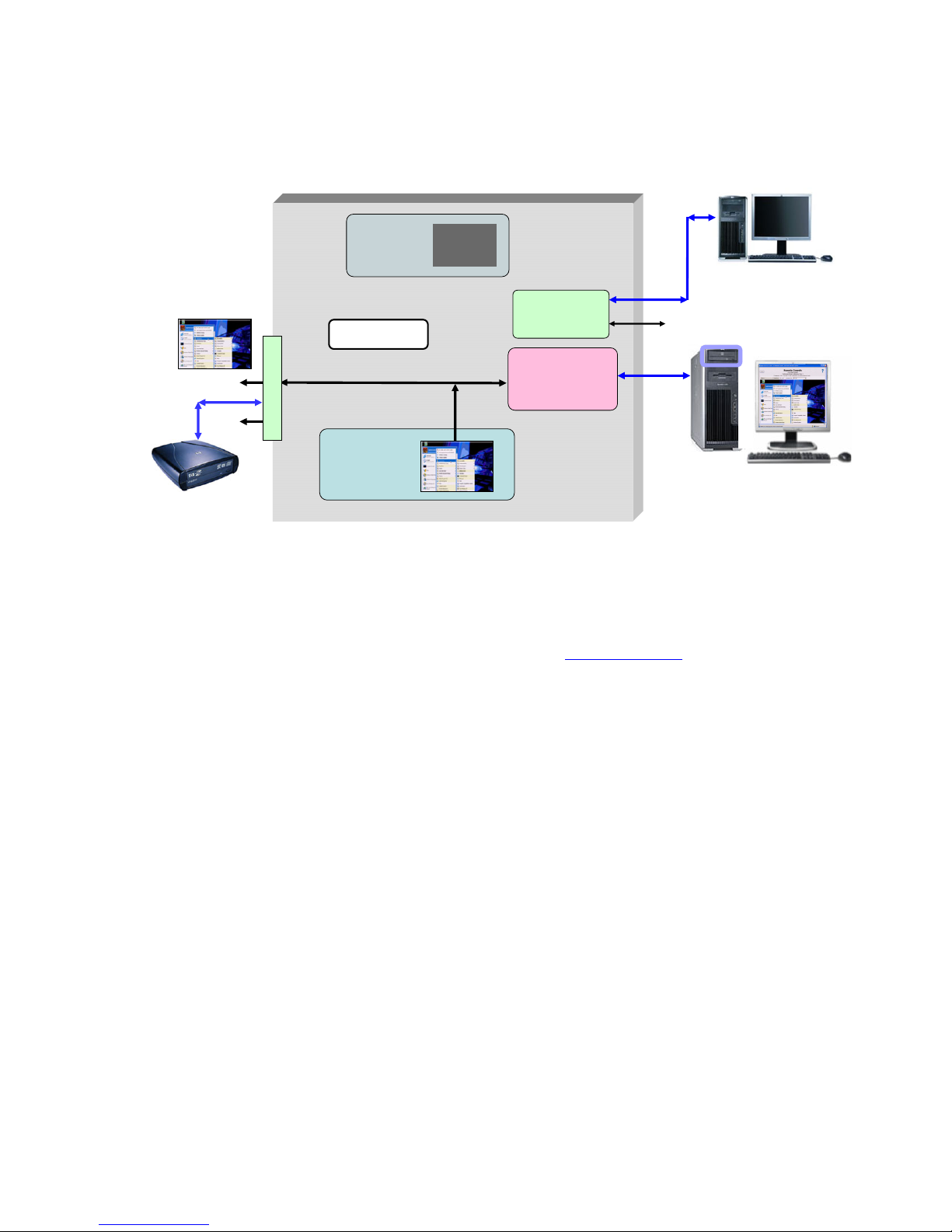
The blade workstation architecture supports three primary methods of connecting media to the blade (such as a
CD/DVD drive). Figure 3-2 shows media connection in Admin Mode.
Figure 3-2 Connecting media to the blade workstation
The three methods of connecting media are:
• Connect media to one of the USB connectors on the Local I/O Cable
• Connect a shared network drive to the blade using Windows XP
• Use iLO 2 virtual media to mount PC media (such as a CD/DVD drive) to the blade workstation. For more
information about iLO 2 virtual media, see Section 12-2-4, “iLO 2 virtual media”.
In addition, the c3000 enclosure supports an optional DVD drive that can be used to install the operating system
or software on a blade workstation. Using the c3000 Onboard Administrator, the DVD drive can be attached to
any or all blade workstations in the enclosure.
Dual Broadcom
5708 Ethernet
controllers
iLO 2
management
processor
ATI RN50
video controller
(1280 x 1024)
NIC 1
NIC 2
iLO 2
Windows
Console
NVIDIA graphics
adapter is not visible
to the operating
system
Admin Mode
CD/DVD drive
iLO 2 virtual media
shared network drive
Virtual CD/DVD
NVIDIA Quadro
FX graphics
adapter
128 MB
USB x 2
local I/O connector
video
serial
Page 25
Installing, powering on, booting, and validating the blade workstation solution 25
3-2-4 Powering on the blade workstation
This section describes how to power on the blade workstation using the factory-installed Microsoft Windows XP32 operating system.
NOTE: The blade power on process can be performed using either the Local I/O Cable or iLO 2 Remote
Console. The advantage of using the Local I/O Cable is that blade verification is not dependent on iLO 2
networking (which, by default, requires a DHCP server to assign the IP address). Using the Local I/O Cable,
you can confirm that the iLO 2 IP address is set as expected—at that point, you have the option of using the
iLO 2 Remote Console.
HP recommends using the Local I/O Cable to power on the first blade workstation. Once it has been verified
(including DHCP assignment of the NIC1, NIC2, and iLO 2 IP addresses), subsequent blade workstations can
be powered on using the iLO 2 Remote Console. This is consistent with the building block approach—start
simple, and build from there. Therefore, the following steps are based on using the Local I/O Cable.
To power on the blade workstation, perform the following steps:
1. Install the blade workstation in the c3000 or c7000 enclosure. Because the blade is hot-pluggable, it can
be inserted and removed while the enclosure is powered.
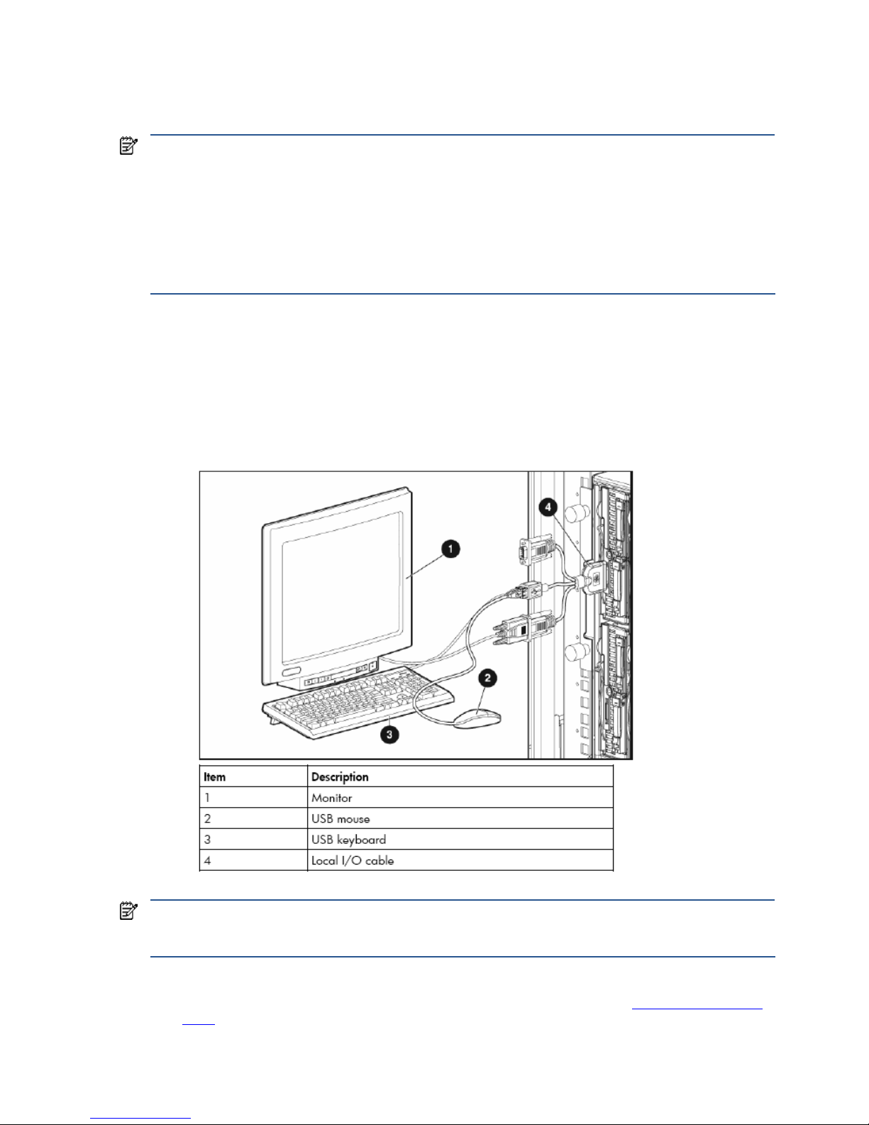
2. Connect the Local I/O Cable to the Local I/O Connector on the front of the blade workstation. Connect a
monitor, USB keyboard, and USB mouse to the Local I/O Cable (see Figure 3-3). Note that the xw2x220c
blade workstation has two Local I/O Connectors, one for Workstation A and one for Workstation B.
Figure 3-3 Connecting a monitor, keyboard, and mouse to the blade workstation
NOTE: Depending on how you interact with the blade workstation and how many USB devices you have
connected to the Local I/O Cable (such as a keyboard and mouse), it might be necessary to add a USB hub to
connect additional USB devices, such as a USB CD/DVD drive.
3. Power on the blade by pressing the front panel Power On button. The boot sequence is displayed on the
monitor. Set Remote Console Mode to Setup Mode as described in Section 2-1, “Setting Remote Console
Mode”. Save the BIOS setting, and continue with the boot process.
Page 26
Installing, powering on, booting, and validating the blade workstation solution 26
3-2-5 Blade workstation sleep states
The blade workstation supports two sleep states: S0 (fully on) and S5 (off but connected to power). No other
power management states (such as Hibernate or Standby) should be used. From sleep state S5, Wake-on-LAN
(WOL) is supported by both NIC1 and NIC2. However, a blade workstation in sleep state s5 will be unable to
respond to an RGS connection request from a client computer, which will result in an RGS connection failure
being displayed on the client computer. Once Wake-on-LAN occurs and the blade workstation boots into
Windows, an RGS connection can be established by the client computer.
3-3 The OOBE screens
When the blade workstation boots the first time, it cycles through a number of OOBE (Out of Box Experience)
screens. These screens enable you to configure several Windows parameters, including:
• Region, keyboard layout, and input language
• Time zone
• End User License Agreement
• Automatic Updates (enable or disable)
• Computer name
• Administrator password
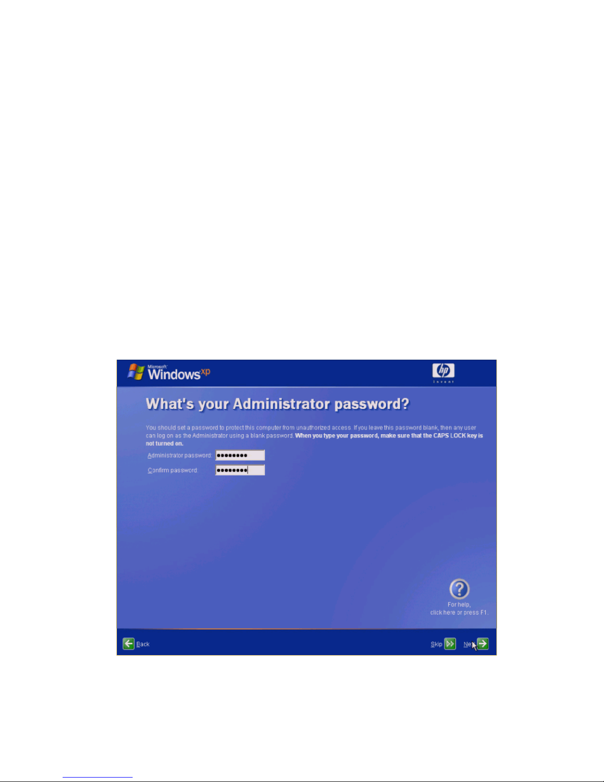
During the OOBE configuration process, the Administrator password screen is displayed (see Figure 3-4). It is
very important to set an Administrator password. Without an Administrator password, RGS cannot authenticate,
and no client connection is possible through an administrator account.
Figure 3-4 The OOBE Administrator password screen
After completing the OOBE process, the blade workstation reboots into Windows.
Page 27
Installing, powering on, booting, and validating the blade workstation solution 27
3-4 Verifying networking
The next step is to verify that the blade workstation is accessible over the network using NIC1, NIC2, and iLO 2.
By default, the NIC1, NIC2, and iLO 2 IP addresses are set by DHCP. Therefore, ensure that the blade
workstation can connect to a DHCP server.
NOTE: The following steps are based on continued use of a keyboard, mouse, and monitor connected to the
Local I/O Cable.
3-4-1 NIC1 and NIC2 verification
The ipconfig command should be used to verify that the NIC1 and NIC2 IP addresses have been set by
DHCP. Alternatively, you can specify a static IP address and Subnet mask for each NIC.
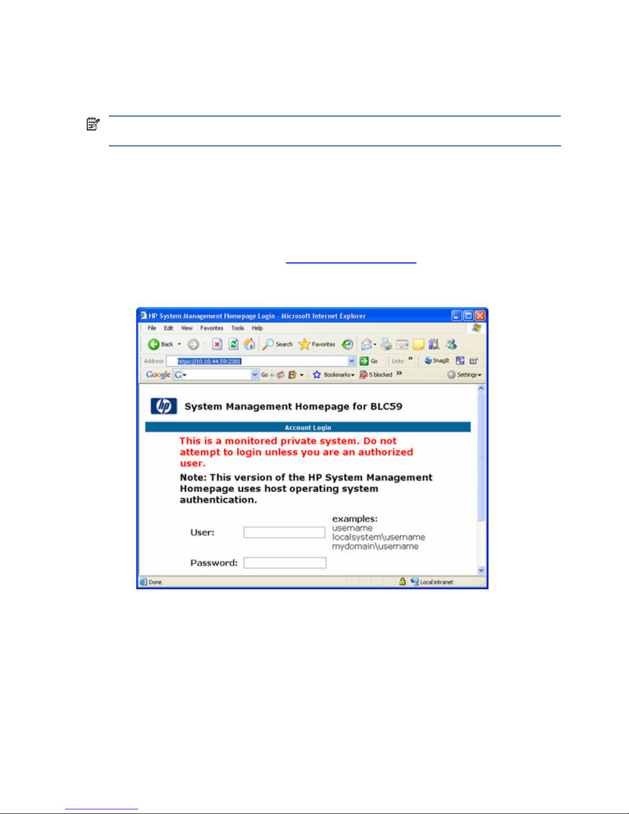
The simplest way to verify NIC1 and NIC2 operation is to access the blade System Management Homepage
(SMH) from your PC. To verify NIC1 and NIC2, point a browser window at each of their IP addresses using
HTTPS protocol and port 2381 (see Figure 3-5). The SMH page should appear using each NIC. For more
information about SMH, see Section 12-4, “System Management Homepage
.”
Figure 3-5 System Management Homepage
Page 28
Installing, powering on, booting, and validating the blade workstation solution 28
3-4-2 iLO 2 network verification
To validate iLO 2 network access, you first need to know the iLO 2 IP address. There are several ways to
determine this:
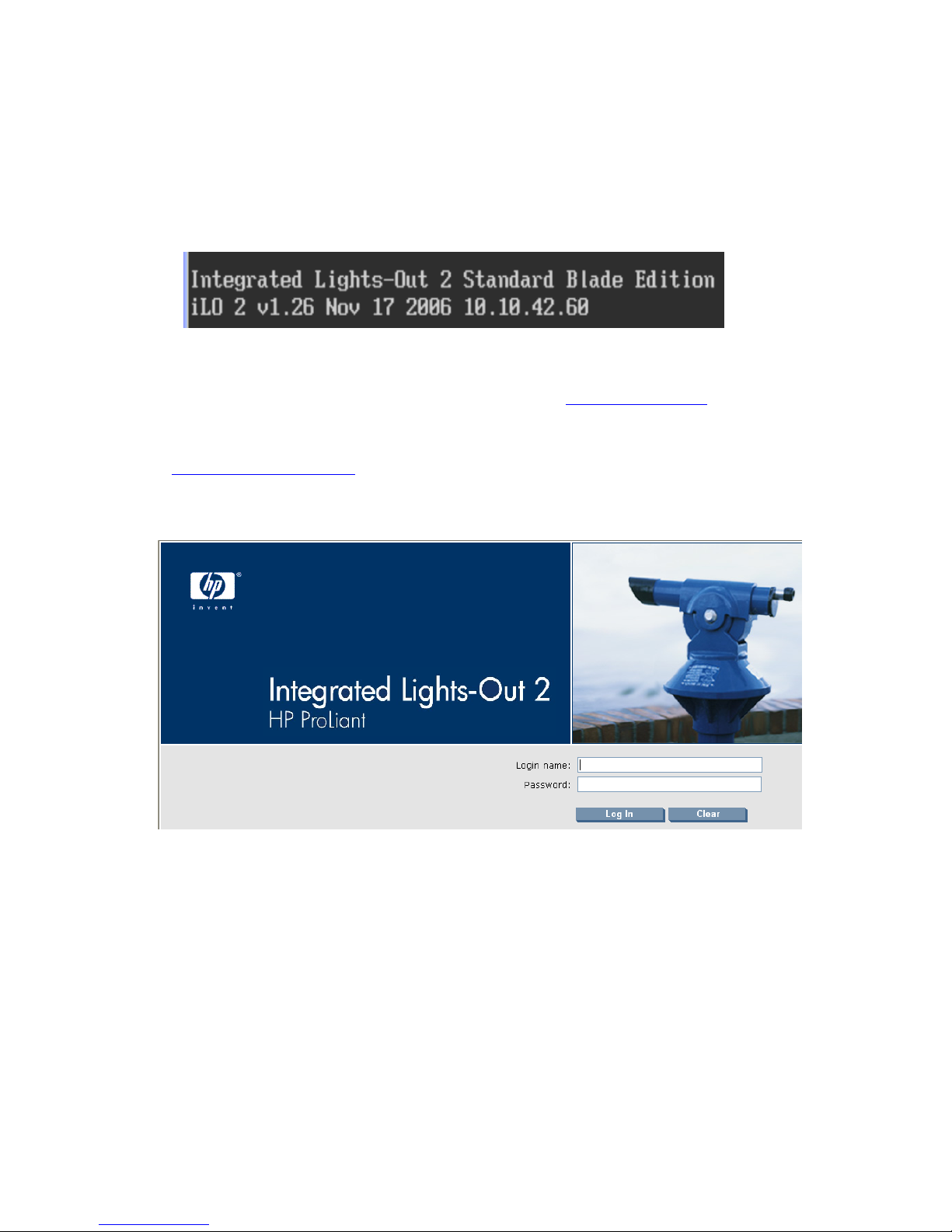
• Reboot the blade. During the reboot, the boot console displays the iLO 2 IP address, as shown in Figure 3-6
(10.10.42.60).
Figure 3-6 Boot console display of the iLO 2 IP address
• Log into SMH, and click Embedded NEC98431 under Management Processor, which displays the iLO 2 IP
address.
• Use Onboard Administrator, as described in Section 12-1, “Onboard Administrator
.”
To validate iLO 2 network access, point your PC browser window to the iLO 2 IP address (again, using HTTPS).
This should display the login screen shown in Figure 3-7. For more information about iLO 2, see Section 12-2,
“Integrated Lights-Out 2 (iLO 2)
.”
Figure 3-7 iLO 2 login screen
Page 29
Installing, powering on, booting, and validating the blade workstation solution 29
3-5 Installing, configuring, and verifying RGS
3-5-1 Installing RGS
RGS (specifically, the RGS Sender) is not factory-installed on the blade workstation. RGS needs to be obtained
from HP, and installed on your blade workstation. A paper License Agreement Certificate is shipped with your
blade workstation that allows you to download RGS 5.1.5 at no cost from HP—see the certificate for
downloading instructions.
Alternatively, you can purchase and install RGS 5.2.0 or later. To purchase RGS 5.2.0, start at the RGS
homepage at www.hp.com/go/rgs
. RGS 5.2.0 and later require installation of a license to operate—for
licensing details, see the HP RGS Licensing Guide, available on the RGS homepage.
Assuming you’ll first download RGS to your PC (not directly to the blade workstation), the RGS Sender installation
software can be made accessible by the blade workstation in several ways, including:
• Map the blade workstation C: drive to your PC, and then copy the RGS files to the blade workstation drive.
• Copy the RGS software to a CD, and then use iLO 2 virtual media from your PC to make the CD accessible
by the blade workstation. For information about iLO 2 virtual media, see Section 12-2-4, “iLO 2 virtual
media”.
Included with the RGS download is the HP Remote Graphics User Guide—refer to this document for detailed
installation instructions. Microsoft Remote Desktop Connection can be used to remotely install the RGS Sender.
IMPORTANT: RGS supports remote USB, which allows USB devices connected to the client computer to be
attached to the blade workstation. This enables the blade workstation to access the USB devices as if they are
connected directly to the blade workstation. During RGS installation, you’ll be asked whether you’d like to
enable remote USB. If you decide later to change remote USB (for example, to enable it from a disabled state),
you’ll need uninstall and reinstall the RGS Sender.
3-5-2 Setting the RGS NIC binding order
Because the blade workstation (the RGS Sender) has two network ports (NIC1 and NIC2), care must be
exercised when establishing a connection from the client computer (the RGS Receiver). It’s possible for the RGS
Sender to be “listening” on one NIC while the RGS Receiver is trying to establish a connection on the other NIC.
The RGS Sender binds to the first NIC detected during booting. To determine the IP address of the first NIC,
perform the following steps on the blade workstation:
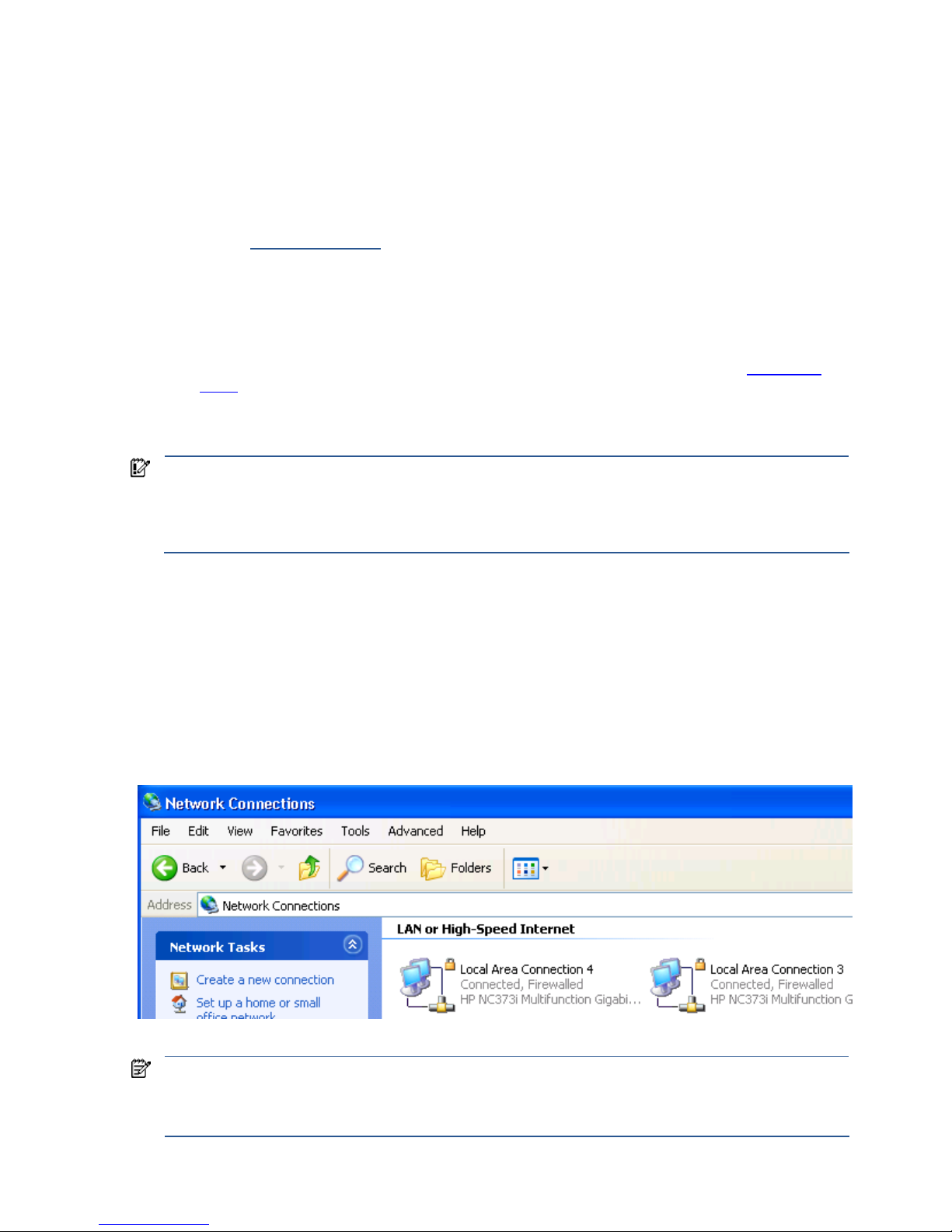
1. To view both NICs, click start > Control Panel > Network Connections (see Figure 3-8).
Figure 3-8 Viewing the two blade workstation NICs
NOTE: The xw460c blade workstation NICs are based on a pair of Broadcom 5708s Ethernet controllers. An
earlier naming convention referred to these controllers as “HP NC373i”, as shown in Figure 3-8. Subsequently,
the naming convention of “Broadcom BCM5708S” was adopted. Independent of the naming convention, the
Ethernet hardware is the same—dual Broadcom 5708s Ethernet controllers.
Page 30
Installing, powering on, booting, and validating the blade workstation solution 30
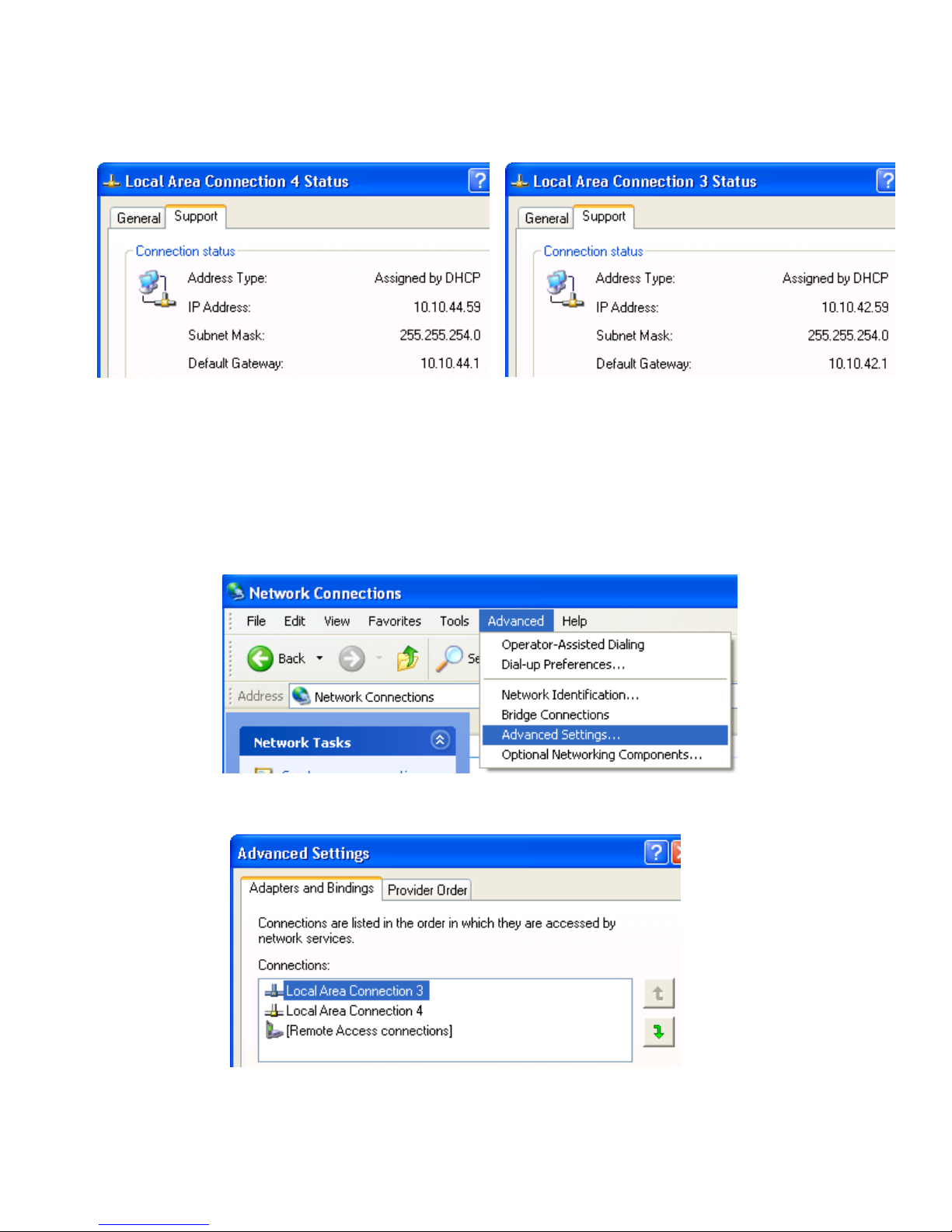
2. Double-click each LAN icon and the Support tab, which displays the IP address of each NIC (see Figure
3-9). While this provides the IP address of each NIC, it does not indicate which NIC is considered the
“first” NIC.
Figure 3-9 NIC IP addresses
3. To determine which NIC is the first NIC, click Advanced > Advanced Setting in the Network Connections
window (see Figure 3-10). The Advanced Settings window is displayed (see Figure 3-11). The “first” NIC is
listed at the top in the Connections box. In Figure 3-11, the first NIC is Local Area Connection 3, which
(from Figure 3-9) has an IP address of 10.10.42.59. This is the NIC that the blade workstation will be
“listening” to for an RGS connection.
Figure 3-10 Determining the first NIC
Figure 3-11 Advanced Settings dialog
The arrows to the right of the Connections box in Figure 3-11 can be used to change the order of the NICs to
specify which NIC will be used by the RGS Sender. In the example in Figure 3-11, the RGS Sender will use Local
Area Connection 3 with an IP address of 10.10.42.59.
Page 31

Installing, powering on, booting, and validating the blade workstation solution 31
3-5-3 Setting User Mode
Before verifying RGS operation, set Remote Console Mode to User Mode. This is necessary because the RGS
Sender can operate only with the NVIDIA graphics adapter (which is active in User Mode). To set Remote
Console Mode to User Mode, reboot the blade workstation, and select User Mode as described in Section 2-1,
“Setting Remote Console Mode
.”
3-5-4 Verifying RGS operation
RGS connections are initiated from the client computer—see the RGS User Guide available at
www.hp.com/support/rgs_manuals
for information on how to establish an RGS connection. While RGS supports
several operating modes, HP recommends that you first attempt to establish a connection in Normal Mode, which
is the simplest operating mode.
IMPORTANT: RGS operation (as characterized by interactivity, security, and reliability) is very dependent on
your network design. For information on optimizing your network design, see the HP Blade Workstation
Solution Planning Guide, available at www.hp.com/support/xw460c_manuals.
3-6 Installing applications
Because the blade workstation does not contain any removable-media storage devices (such as a CD/DVD drive
or diskette drive), the first step when installing applications is to make the application installation package
accessible by the blade. The four most common methods to make the package accessible are:
• Blade hard drive—Copy the application installation package over the network to the blade workstation
hard drive, and run the installation from the hard drive.
• PC hard drive—Copy the application installation package to the hard drive of your PC. Log into the blade
workstation from your PC using RGS, and then map the PC hard drive to the blade. Using RGS, run the
installation package on the blade using the mapped network drive from the PC. A variation of this method
is to save the installation package on a shared network drive, map the shared drive to the blade, and then
install the application from the network drive.
• Local I/O Cable CD/DVD drive—Connect a USB CD/DVD drive to the Local I/O Cable, and install the
application from a CD or DVD.
• iLO 2 virtual media—From your PC, use iLO 2 to connect to the blade workstation. Use the iLO 2 Remote
Console and Virtual Media capabilities (see Section 12-2-4, “iLO 2 virtual media
”) to connect the required
media device from the PC to the blade workstation.
Once the application installation package is accessible by the blade workstation, the installation can be initiated
from the following devices:
• Your PC, by using either:
• RGS (requires User Mode)
• iLO 2 Remote Console (requires Admin Mode or Setup Mode)
• Microsoft Remote Desktop Connection
• A keyboard, mouse, and monitor connected to the Local I/O Cable
Page 32

Installing, powering on, booting, and validating the blade workstation solution 32
Each installation method has advantages and limitations:
• Local installation using USB devices connected to the Local I/O Cable—This is generally the most reliable
method, particularly for installations requiring multiple media. However, this method requires that you be
physically present at the blade, which can be difficult in data centers not designed to accommodate local
personnel. A variation of this approach is to only attach the media using the Local I/O Cable, and then
interact with the blade workstation remotely using RGS, RDC, or the iLO 2 Remote Console. However,
manipulating media locally at the blade workstation while interacting remotely can be cumbersome.
• Copying the installation package to a hard drive (either on the blade workstation or the PC)—This method
might not be possible, depending on the application installation procedure used. In particular, installations
requiring multiple CDs or diskettes may not work with this method.
• Applications that depend on detection of the NVIDIA graphics adapter—The iLO 2 Remote Console and
Local I/O Cable environments both require that the ATI video controller is displaying the Windows desktop.
If application installation depends on detection of the NVIDIA graphics adapter, an incorrect installation
may result.
• Using RDC—If application installation depends on detection of the NVIDIA graphics adapter, an incorrect
installation may result.
• Application installations that require a midway reboot—Both the Windows RDC and RGS environments
terminate their connections when the blade reboots. If application installation requires a midway reboot,
RDC or RGS reconnection is required after the reboot.
After selecting the application installation method, install the applications using the installation process specified
by each application.
3-7 Validating the solution
Verifying correct installation and functionality of the solution is similar to verification of a standalone workstation.
To validate the solution, launch the blade workstation applications from the client computer. Verify the
applications work correctly, and provide the expected functionality, performance, and interactivity.
3-8 Integrate additional blade workstations and client computers
The integration of additional blade workstations and client computers is a step-and-repeat process. To ensure that
each added device operates correctly with the existing solution components, it is recommended that you perform
validation after each blade workstation and client computer is installed. For example, after integrating a new
blade workstation into the solution, you should validate that RGS operates between the new blade workstation
and an existing client computer.
3-9 Optional: Configure network teaming
The two Broadcom Ethernet controllers can be teamed together to provide more robust network connectivity,
improving reliability, performance, or both. Network teaming is configured using the Broadcom Advanced
Control Suite (BACS), which is factory-installed on the blade workstation. BACS supports two types of network
teams, each of which has two variations:
1. Load balance/failover teaming—This team type provides redundant network connections, enabling a link to
stay active even if one network adapter (or the switch it connects to) fails. Network adapters are
configured as either load balance or failover members of the team. If a load balance member fails, a
failover member is activated. There are two versions of this team type available via BACS:
• Smart Load Balancing™ and Failover —This type of team detects when a load balance team member
fails, and automatically switches to another network adapter in the team. If all load balance adapters
fail, the failover members are used. When a load balance adapter is again available, network traffic
shifts back to the newly-available load balance adapter.
• SLB (Auto-Fallback Disable)—This type of team is similar to the Smart Load Balancing™ and Failover
team described above, except that, once a failover adapter is used, the network traffic will not
automatically return to a load balance adapter if it becomes available.
Page 33

Installing, powering on, booting, and validating the blade workstation solution 33
2. Link aggregation (trunking)—This team type provides redundancy and increased network bandwidth by
using multiple network adapters as a single virtual adapter. The link partner (usually a switch) for these
network adapters must include support for this type of team. There are two different types of link
aggregation teams supported by BACS:
• 802.3ad (using Link Aggregation Control Protocol, or LACP)—Multiple network adapters are teamed
together, providing an aggregation of network bandwidth between the computer and the link partner
(switch). For example, teaming three 1 Gb/s adapters together allows for a theoretical transfer rate of
3 Gb/s between the computer and the switch.
If any network adapter fails, the network connection will remain active using the remaining team
members, although performance will be reduced by loss of the team member. The switch will be
automatically configured to recognize the 802.3ad team using LACP (assuming, of course, that the
switch supports LACP).
• Generic Trunking (FEC/GEC)/802.3ad-Draft Static—This mode is similar to the 802.3ad team described
above, except that it is based on an early (draft) version of the IEEE specification, and does not include
LACP. Thus, the switch (which must include support for this mode) must be manually configured with
teaming information. Only a few switches implemented this teaming method; it is included here for
completeness.
BACS is started as follows:
start > All Programs > Broadcom > Broadcom Advanced Control Suite 2
Once BACS is started, click the Help button for information on the different types of teams as well as
detailed information on how to create a team. Specifically, go to Configuring Teaming in the Using
Broadcom Advanced Control Suite 2 section.
BACS can also be used to configure a Virtual LAN (VLAN). For information on configuring a VLAN, refer to
the VLAN-related sections in the Configuring Teaming section.
Page 34

Creating a custom Windows XP-32 image 34
4 Creating a custom Windows XP-32 image
This chapter describes how to create a custom Windows XP Professional SP2 image for the blade workstation.
First, as reference, the components included in the factory-installed Windows XP-32 operating system are listed.
In most cases, you’ll want to include these components in your custom Windows XP-32 image.
4-1 Components in the factory-installed Windows XP-32 image
The Windows XP-32 operating system that is factory-installed on your blade workstation contains a number of
drivers and agents. To create a custom Windows XP-32 operating system image, ensure that the following
software, drivers and agents are included:
• Microsoft Windows XP Professional Service Pack 2
• Device drivers
• HP SmartArray E200i SAS controller driver
• ATI ES1000 graphics driver
• NVIDIA FX graphics driver
• Broadcom NetXtreme 5708 Gigabit LAN driver
• HP ProLiant Integrated Lights-Out 2 (iLO 2) Management Interface driver
• HP ProLiant iLO 2 Advanced and Enhanced System Management Controller health driver
• Management components
• HP Insight Management Agents
• HP System Management Homepage (SMH) for Microsoft Windows
• SNMP (Simple Network Management Protocol) – SNMP is required for the HP Insight Management
Agents and System Management Homepage.
• Applications
• Microsoft .NET Framework 1.1
• Sun Java Virtual Machine
• Adobe® Acrobat® Reader
• Microsoft QFE (Quick Fix Engineering) defect fixes
• Windows 2007 Time Zone Update (Q928388)—This QFE is available on the blade workstation
support website as a SoftPaq. See APPENDIX A: Downloading and installing SoftPaqs and Smart
Components for information on finding and downloading this SoftPaq.
• HTML Help Vulnerability (Q896358)—See support.microsoft.com/kb/896358
• DhcpRequestParams function broken on Windows XP SP2 (Q885270)—See
support.microsoft.com/kb/885270/en-us
• DEP-enabled Windows XP SP2 computer may fail resume (Q889673)—See
support.microsoft.com/kb/889673/en-us
• Vulnerabilities in Windows kernel (Q890859)—See support.microsoft.com/kb/890859
The factory-installed Windows XP-32 operating system contains the following configuration parameters to
optimize performance and manageability:
• Remote Desktop Connection is enabled.
• Internet Connection Firewall configuration.
• Remote Assistance is allowed.
• Remote Desktop is allowed.
• Remote Graphics Software connections are allowed.
• ICMP echo requests are processed.
• Ports necessary for HP Systems Insight Management are enabled.
• Ports necessary for Rapid Deployment Pack to re-image the blade are enabled. This requires installation
of the Aclient software.
Page 35

Creating a custom Windows XP-32 image 35
• Modified local security policy—The network access sharing and security model for local accounts is set to
Classic, meaning, local users authenticate as themselves. This setting is necessary to permit RGS
connections when the blade workstation is not part of a Microsoft Windows domain.
• The Windows power options are set to never turn off any component, and never sleep or hibernate.
• The Windows desktop wallpaper is set to a solid color to maximize remote video performance.
• The default is that NIC1 and NIC2 will obtain their IP addresses using DHCP.
4-2 Creating a custom Windows XP-32 image
There are several ways to create a custom Windows image. This section describes the most basic method—using
the Windows XP-32 CD, and adding the required software such as device drivers. All interactions are
accomplished using a keyboard, mouse, CD/DVD drive, and monitor connected to the Local I/O Cable.
4-2-1 Required components
To create a custom Windows image, the following software and hardware components are required:
• A means of connecting a diskette drive and a CD/DVD drive to the blade. This connection can be made in
two ways:
• Local I/O Cable—Connect a USB hub, USB keyboard, USB mouse, USB CD/DVD drive, USB diskette
drive, and a monitor to the Local I/O Cable. A USB hub is required because the Local I/O Cable only
has two USB connectors while four are required.
• PC—From a PC, use iLO 2 Remote Console and virtual media to connect a diskette drive and CD/DVD
drive to the blade (see 12-2-4, “iLO 2 virtual media
”).
• Microsoft Windows XP Professional CD with integrated Service Pack 2—The Microsoft Volume License
media or a retail version can be used. The retail CD requires online activation of the final installed
operating system or it will stop functioning after 30 days. There is no activation required with Volume
License media. Unlike other HP workstation products, operating system installation cannot be performed
using the Windows XP SP2 operating system CD included in the Restore Plus! CD set.
• HP Remote Graphics Software—This CD is required for installation of the RGS Sender on the blade
workstation.
NOTE: To download the software listed below, follow the steps outlined in “APPENDIX A: Downloading and
installing SoftPaqs and Smart Components”. When prompted to select the operating system, select Microsoft
Windows XP Professional (this is Windows XP-32).
• Diskette containing the HP Smart Array E200i SAS controller drivers—Store the following files in the root
directory of a diskette:
• hpcissm2.cat
• hpcissm2.sys
• hpcissx2.inf
• txtsetup.oem
• CD containing the following required drivers—Download and store the following SoftPaqs on a CD:
• ATI ES1000 graphics driver
• NVIDIA FX graphics driver
• Broadcom NetXtreme 5708 Gigabit LAN driver
• HP ProLiant Integrated Lights-Out 2 Management Interface driver
• HP ProLiant iLO 2 Advanced and Enhanced System Management Controller health driver
Page 36

Creating a custom Windows XP-32 image 36
4-2-2 Optional software components
The following software components are optional, and can be downloaded from the blade workstation software
and drivers website:
• CD containing System Management Homepage (SMH)—SMH allows the status of the blade to be remotely
monitored (see Section 12-4, “System Management Homepage
“).
• CD containing HP Insight Management Agents—The Management Agents are required if SMH is installed,
or if HP Systems Insight Manager is used to remotely manage the blade (see Section 12-5, “HP Systems
Insight Manager “).
4-2-3 Creating the Windows XP-32 image
Follow these steps to create the Windows XP-32 image using the Microsoft Windows XP-32 CD:
1. Connect a monitor, USB hub, keyboard, mouse, diskette drive, and CD/DVD drive to the Local I/O Cable
(see Figure 3-3).
2. Cycle power on the blade to initiate a reboot. When the BIOS console appears, change the BIOS Remote
Console Mode to Setup Mode as described in Section 2-1, “Setting Remote Console Mode
.” Setup Mode
causes the NVIDIA graphics adapter and ATI video adapter to both be visible to the Windows operating
system to ensure correct driver installation.
3. Boot the blade workstation from the Windows XP-32 CD.
4. Immediately after booting Windows from the CD, press the F6 key when prompted (see Figure 4-1). This
step is required to install third-party drivers. In Figure 4-1, the HP Smart Array E200i SAS storage driver is
installed.
Figure 4-1 Windows setup screen
IMPORTANT: The F6 key must be pressed quickly. If not pressed quickly, the installation process will continue
but, at a later step, Windows will fail to boot because of the missing SAS storage driver.
Page 37
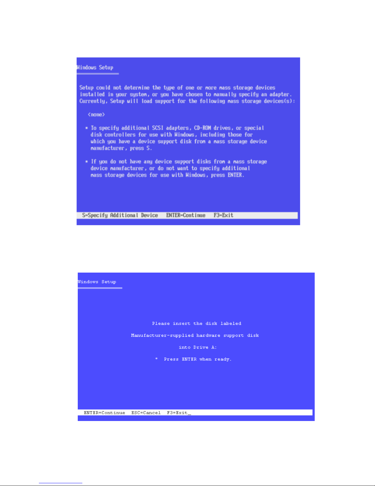
Creating a custom Windows XP-32 image 37
5. When prompted, press the S key (see Figure 4-2) to indicate the availability of a diskette with the E200i
SAS drive. Press Enter to continue.
Figure 4-2 Mass storage setup screen
6. When prompted for the driver diskette (see Figure 4-3), insert the diskette containing the HP Smart Array
E200i SAS controller drivers, and press Enter to continue.
Figure 4-3 Storage driver prompt screen
Page 38
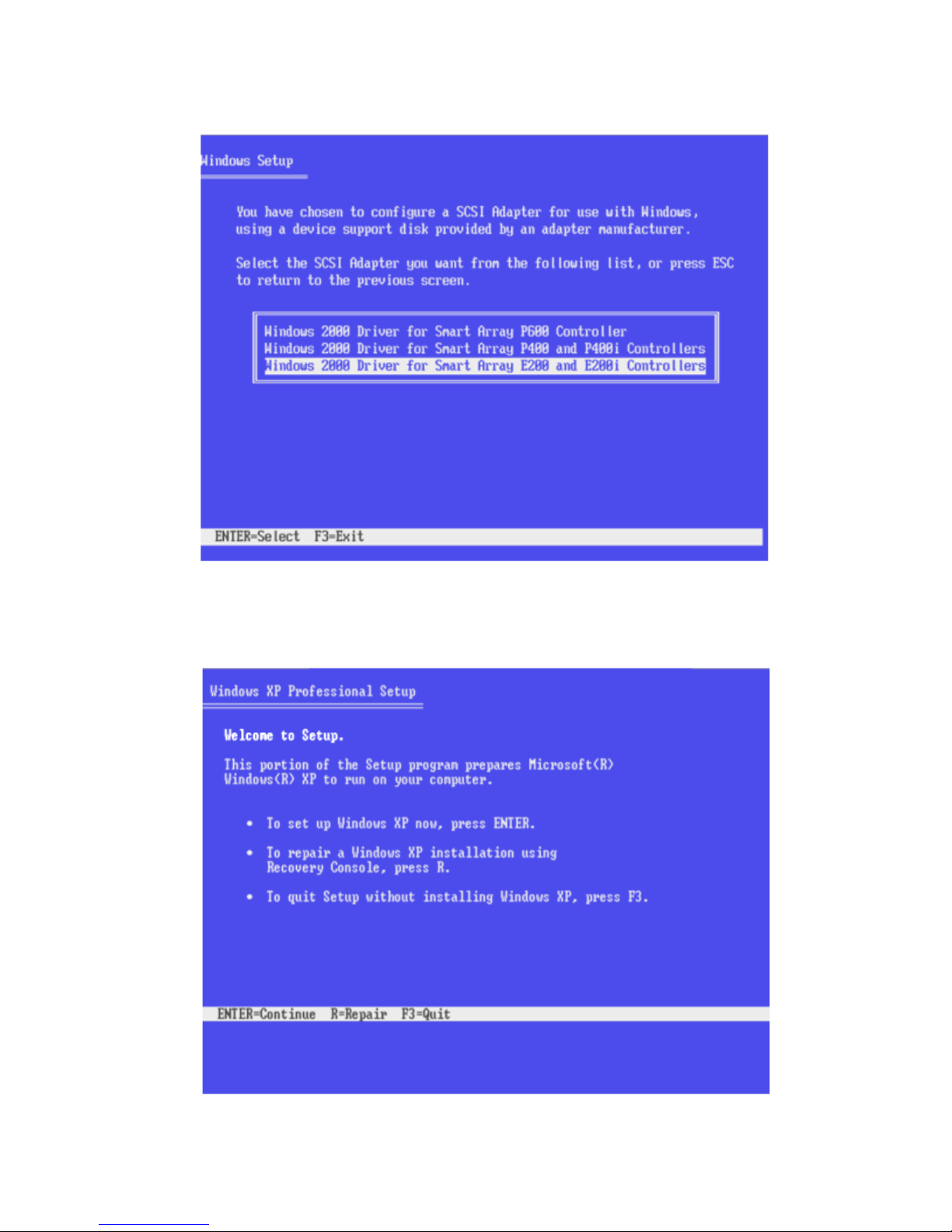
Creating a custom Windows XP-32 image 38
7. Select the Windows 2000 Driver for Smart Array E200 (see Figure 4-4). Press Enter to install the driver.
Figure 4-4 SCSI adapter selection screen
8. When prompted, press Enter to begin the Windows XP installation (see Figure 4-5).
Figure 4-5 Windows XP Pro setup screen
Page 39
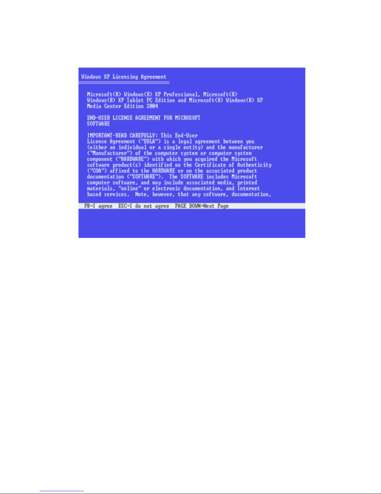
Creating a custom Windows XP-32 image 39
9. When prompted, select the manual installation option.
10. When prompted, press F8 to accept the Microsoft End-User License Agreement (see Figure 4-6).
Figure 4-6 Windows XP EULA
11. Partition the hard drive as desired.
12. Install Windows XP Pro in a fresh partition.
Page 40
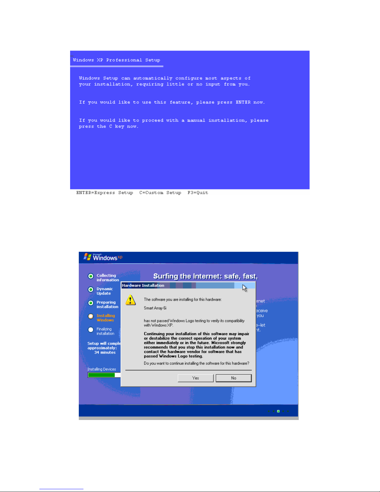
Creating a custom Windows XP-32 image 40
13. Enter C to proceed with manual installation (see Figure 4-7).
Figure 4-7 Windows setup manual installation screen
14. If the Windows setup GUI prompts you for unsigned drivers, click Yes to install drivers that have not passed
Windows Logo testing (see Figure 4-8).
Figure 4-8 Windows logo testing screen
Page 41
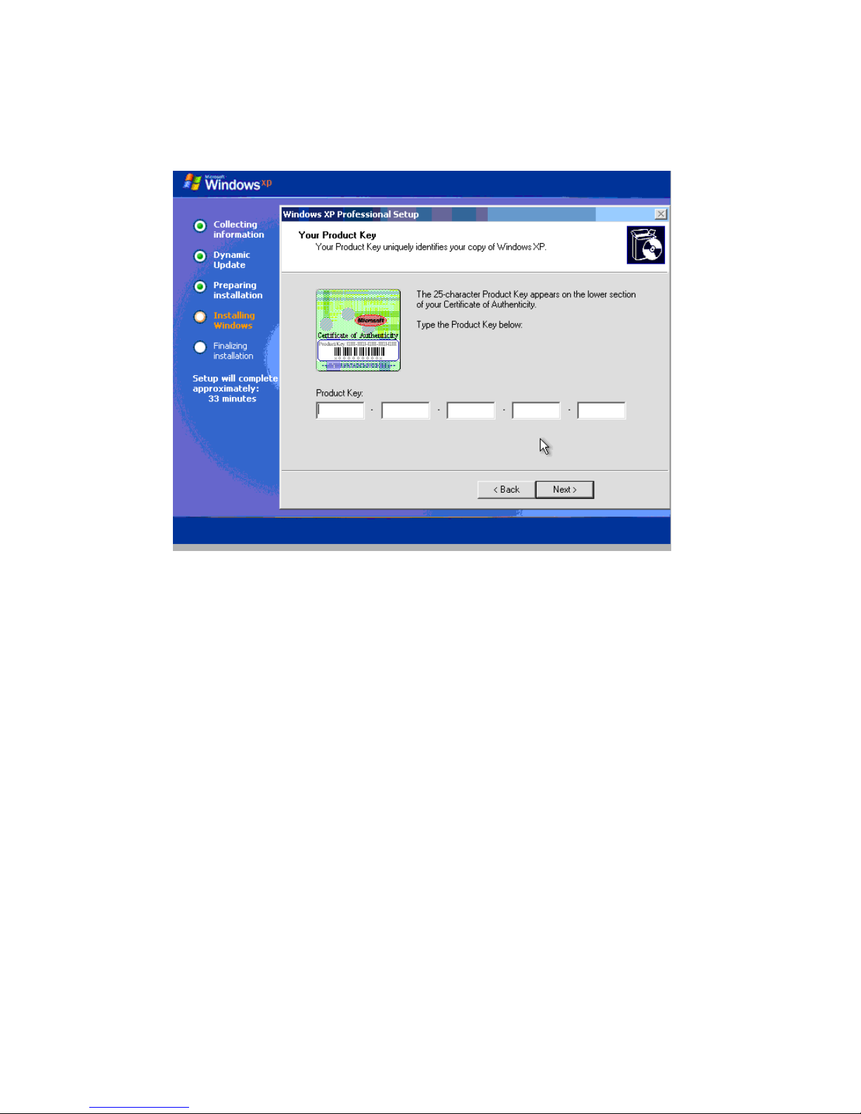
Creating a custom Windows XP-32 image 41
15. Customize Windows XP Pro by answering the Microsoft Out Of Box Experience (OOBE) questions, such as
the time zone and computer name.
16. Enter the 25-character product key that identifies your copy of Windows XP Professional (see Figure 4-9).
Figure 4-9 Product key screen
17. Set the regional and language options.
Page 42
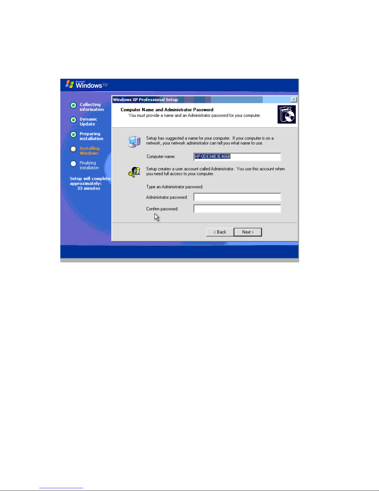
Creating a custom Windows XP-32 image 42
18. From the Computer Name and Administrator Password screen (see Figure 4-10), enter an Administrator
password (required for the blade workstation). Both RGS and Windows Remote Desktop Connection
require access to a password-protected account. The password enables most of the remaining system
configuration and application installation tasks to be performed over the network using RGS or Remote
Desktop Connection.
Figure 4-10 Computer Name and Administrator Password screen
19. Install the following drivers:
• ATI ES1000 graphics driver for the ATI video controller
• Broadcom NetXtreme Gigabit LAN driver for the BCM 5708
• NVIDIA Quadro FX graphics adapter driver
• HP ProLiant Integrated Lights-Out 2 Management Interface driver
• HP ProLiant iLO 2 Advanced and Enhanced System Management Controller health driver
20. Installation of the following QFEs (Quick Fix Engineering) is recommended. See Section 4-1 for the URL of
each QFE.
• Windows 2007 Time Zone Update (Q928388)
• HTML Help Vulnerability (Q896358)
• DhcpRequestParams function broken on SP2 (Q885270)
• DEP enabled Windows SP2 system fail resume (Q889673)
• Vulnerabilities in Windows XP-32 kernel (Q890859)
Page 43
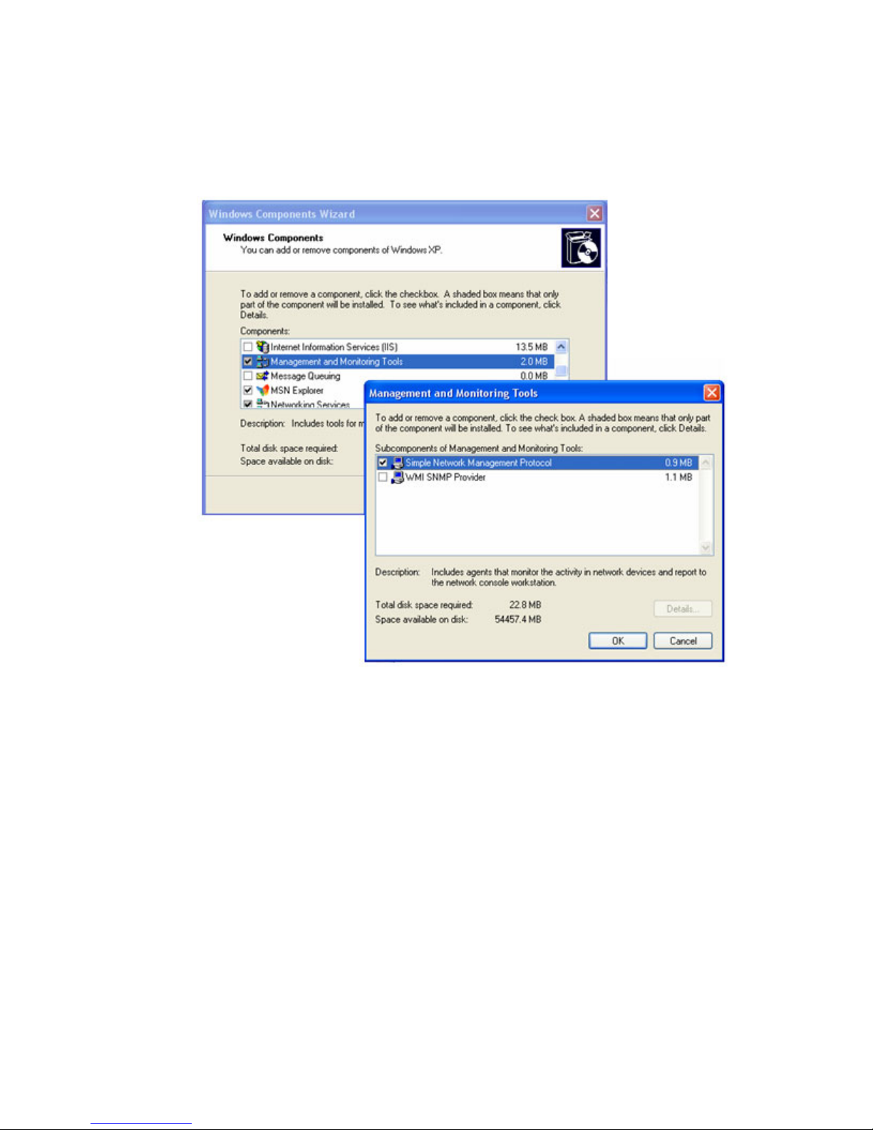
Creating a custom Windows XP-32 image 43
21. If you are installing the management agents (recommended), two additional components are required,
which must be installed in the following order:
a. SNMP (Simple Network Management Protocol)—This component is installed as follows:
• Open the Windows Components Wizard (see Figure 4-11). Select Management and Monitoring
Tools, and click Details. Select Simple Network Management Protocol, and then click OK.
Figure 4-11 Installation of SNMP
Page 44
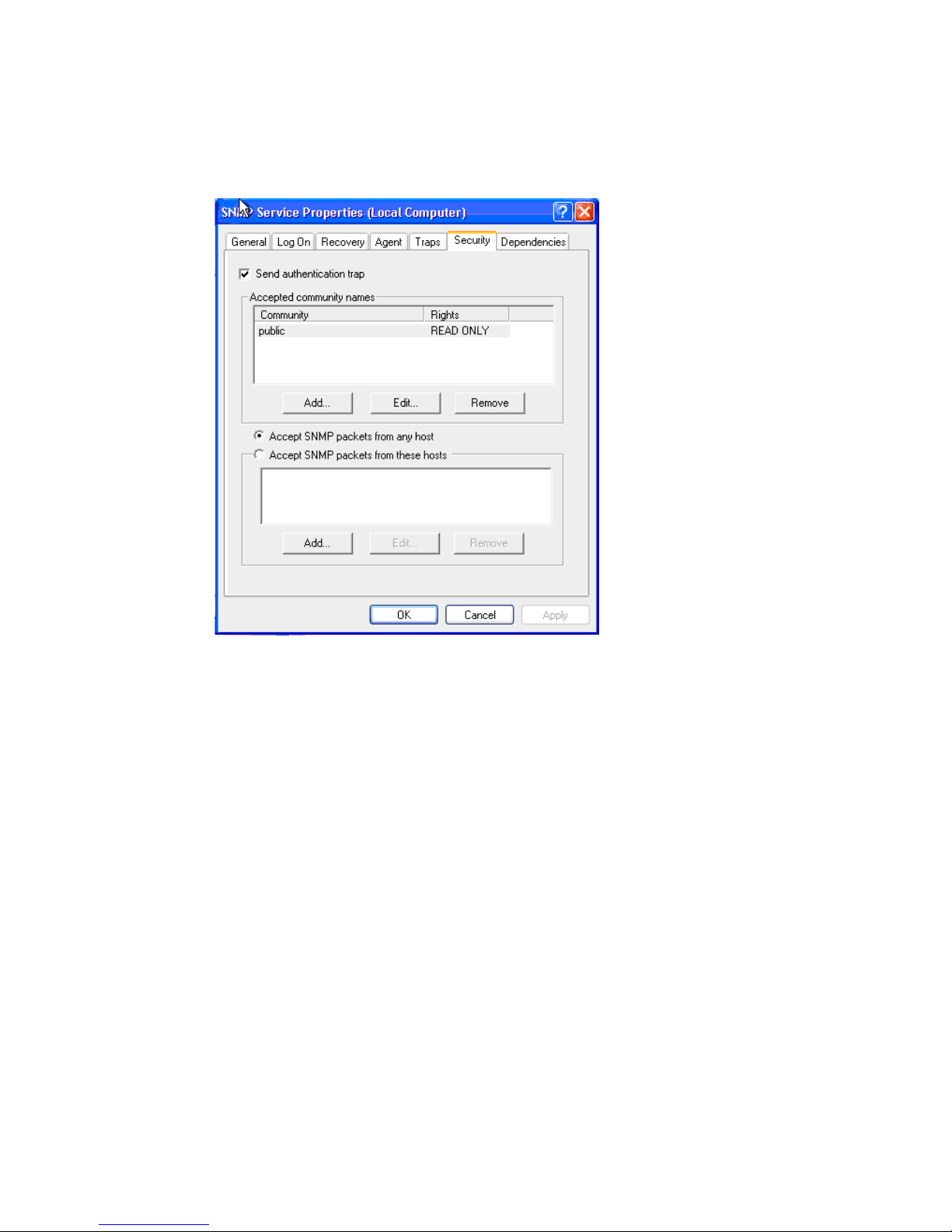
Creating a custom Windows XP-32 image 44
• Next verify that SNMP Service in the Windows Component Services box shows “Started”. Right
click SNMP Service, select Properties, and then click the Security tab. Ensure that the properties
appear as shown in Figure 4-12. If not, modify the Accepted community names as shown. Other
community names may be used. If you want to be able to modify the Integrated Management Log
via the management agents, you must have a READ WRITE community defined.
Figure 4-12 SNMP service properties
b. HP Insight Management Agents—This is the second component that is required in order to use SMH or
HP Systems Insight Manager.
22. Install SMH if required.
Page 45

Creating a custom Windows XP-32 image 45
4-2-4 Configuring the operating system
After Windows starts, configure the operating system as follows:
1. Configure a solid-color Windows wallpaper to maximize RGS performance.
2. Configure Wake-on-LAN, if needed.
3. Turn off all power management functions (for example, hibernation) so that the blade workstation is always
powered-on, and available to respond to requests.
4. Configure the start > Shut Down menu to have two options, Restart and Log off. The Shut down, Stand by,
and Hibernate options should be removed because they require administrator intervention to power up the
blade.
5. Configure the Windows Firewall—The Windows XP Professional SP2 Internet Connection Firewall has
default settings that are too restrictive for many of the remote access and management functions. The
following firewall exceptions are recommended:
• Windows Remote Desktop Connection—“Remote Desktop” program exception
• Windows Remote Assistance—“Remote Assistance” program exception
• Windows File and Print Sharing (required for Rapid Deployment Pack)—“File and Printer Sharing”
program exception
• HP Remote Graphics Software—Add “C:\Program Files\Hewlett-Packard\
Remote Graphics Sender\rgsender.exe” program exception
• System Management Homepage (SMH)—Add the port exceptions listed in Table 4-1.
Table 4-1 HP System Management Homepage port exceptions
Description Port Protocol
HP SMH Web Server* 2301 HTTP
HP SMH Secure Web Server* 2381 HTTPS
WBEM/WMI Mapper 5988 HTTP
WBEM/WMI Mapper (Secure) 5989 HTTPS
SSH Port 22 SSH
SNMP Agent 161 SNMP
SNMP Agent 162 SNMP TRAP
Ping Discovery (ICMP) ICMP
Ping Discovery (TCP) 80 HTTP
Management Processor 443 HTTPS
To allow browser access to SMH, ports 2301 and 2381 must be enabled.
NOTE: When configuring ports for HP SMH and HP SIM, refer also to the HP Customer Advisory “HP Systems
Insight Manager and HP System Management Homepage Do Not Function Properly After Upgrade to
Microsoft Windows XP SP2”. This advisory can be found by searching on the Customer Advisory number,
“c01202170”, in the search box at www.hp.com
.
• Add the port exception listed in Table 4-2 for the RGS Sender:
Table 4-2 RGS Sender port exception
Description Port Protocol
RGS Sender 42966 SSL
Page 46

Creating a custom Windows XP-32 image 46
• If HP Rapid Deployment Pack (HP RDP) is used, enable the “File and Print Sharing” program exception.
Also add the port exceptions listed in Table 4-3 to enable HP RDP access to the blade workstation.
Table 4-3 HP RDP port exceptions
Port Type Description
53 TCP RDP DNS and SQL
53 UDP RDP DNS
67 TCP RDP DHCP REQ
68 TCP RDP DHCP REP
69 TCP RDP M-TFTP
80 TCP RDP iLO and HTTP
88 TCP RDP Kerberos
88 UDP RDP Kerberos
123 UDP RDP SNTP
126 TCP RDP SNMP
135 TCP RDP AeXNS, DCOM, and SQL
135 UDP RDP AeXNS and DCOM
137 TCP RDP Netlogon SMB and SQL
161 TCP RDP SNMP
162 TCP RDP SNMP
389 UDP RDP LDAP ping
389 TCP RDP LDAP
401 TCP RDP WOL
402 TCP RDP Dep Agnts
445 UDP RDP MS-DS
636 TCP RDP SSL LDAP
750 TCP RDP Win2K AD
751 TCP RDP Win2K AD
752 TCP RDP Win2K AD
753 TCP RDP Win2K AD
754 TCP RDP Win2K AD
1010 TCP RDP PXEConfig
1433 TCP RDP SQL
1500 TCP RDP RPC
1758 TCP RDP TFTP
1759 TCP RDP TFTP
2381 TCP RDP RDP Web Agent
2500 TCP RDP RPC
4011 TCP RDP Ext DHCP PXE
Page 47

Creating a custom Windows XP-32 image 47
4-2-5 Verifying the network connections
Verify network connections to the blade workstation as described in Section 3-4, “Verifying networking.”
4-2-6 Installing and verifying RGS
Install and verify RGS as described in Section 3-5, “Installing and verifying RGS.”
4-2-7 Installing the applications
It is recommended that you install the following applications before installing user applications:
• Microsoft .NET Framework—This software is required by many Windows applications.
• Sun Java Virtual Machine (JVM) for Internet Explorer—This software is required to use iLO 2 Remote
Console capabilities that depend on a JVM-enabled browser.
• Adobe Acrobat Reader—This software is required to view .pdf files.
• Altiris Aclient—This software is required to use HP Rapid Deployment Pack to image the blade workstation.
Install the user applications as described in Section 3-6, “Installing applications
.”
4-2-8 Validating the solution
Validate the solution as described in Section 3-7, “Validating the solution.”
4-2-9 Deploying the Windows image
To deploy the Windows image, perform the following steps:
1. Run sysprep to generate new security IDs on each target system.
2. Capture the image.
3. Deploy the image to the blade workstations.
Page 48

Restoring Windows XP-32 48
5 Restoring Windows XP-32
This chapter describes how to restore Windows XP-32 using the RestorePlus! CD and the Windows XP operating
system CD. The restored operating system differs slightly from the factory-installed operating system. For example,
several applications are not included on the RestorePlus! CD because of space limitations.
The restore process repartitions and reformats the blade workstation hard drive. Because all files are deleted from
the hard drive during this process, be sure to archive all important files before beginning.
5-1-1 Hardware configuration
There are two primary ways to restore the Windows XP-32 image:
1. Run the restore process using devices attached to the Local I/O Cable—USB hub, keyboard, mouse,
CD/DVD drive, and a monitor.
2. Run the restore process using iLO 2 virtual media from your local PC—Note that this method is slower than
the above method, and is susceptible to network issues.
In the description of the restore process in the next section, references to “CD/DVD drive” refer either to a USB
CD/DVD drive connected to the Local I/O Cable, or a CD/DVD drive on your client PC connected to the blade
through iLO 2 virtual media.
5-1-2 Restoring Windows XP-32 from the RestorePlus! CD
1. Insert the RestorePlus! CD into the CD/DVD drive.
2. Boot the blade workstation from the CD. When the GUI Language selection screen appears, select a
language (for the restore process, not the operating system), and click Next.
3. After selecting the GUI Language for the restore process, a warning message appears advising you that all
data will be erased from your primary hard disk drive. Click Begin.
4. Select the operating system language based on the language supported by the operating system CD
included with your blade workstation. Click Next.
5. Another warning message appears. Click Next.
6. You are given a choice of partitioning schemes. The default partitioning scheme uses the entire disk drive
for the C: partition. To select a different partitioning scheme, use the blue arrows to make your selection.
Click Next.
7. After requesting confirmation of the hard drive erasure two more times, the restore process partitions and
formats the hard drive. Files are then copied from the RestorePlus! CD to the hard drive and you are
prompted to insert the operating system CD. Insert the CD and click Next.
8. Files are copied from the operating system CD to the hard drive. When prompted, remove the operating
system CD.
9. When prompted for an optional Supplemental CD, click Skip to proceed without one.
NOTE: The application CDs are not Supplemental CDs.
10. When prompted for a Special Content CD, click Skip if you do not have a Special Content CD.
11. When a message appears advising you that the CD-specific portion of the process is complete, click Begin
Setup. The remainder of the installation process runs entirely from the hard drive.
12. The restore process automatically begins installing software. When the Microsoft Out-Of-Box-Experience
(OOBE) screens appear, answer the questions specific to your installation.
13. After entering the OOBE information, click OK to reboot into a fully functional Windows XP-32 operating
system.
Page 49

Using Windows XP-64 on the blade workstation 49
6 Using Windows XP-64 on the blade workstation
While Windows XP-64 is supported on the blade workstation, this OS is not available factory-installed. Windows
XP-64 needs to be acquired, installed, and configured by your IT department. Because so many of the Windows
XP-64 processes are similar to the processes for Windows XP-32 (as described in Chapters 4 and 5), this chapter
focuses on those processes that are different or unique for Windows XP-64.
6-1 Windows XP-64 processes
This section assumes you are familiar with Chapter 4, “Creating a custom Windows XP-32 image,” and Chapter
5, “Restoring Windows XP-32
.” Building on these chapters, this section describes the key differences in how
Windows XP-64 is deployed compared to Windows XP-32. The key aspects are:
• First, of course, you’ll need to acquire the Windows XP-64installation media from Microsoft.
• For a list of hardware and software that is supported on Windows XP-64, see the document Hardware and
Software Supported by HP ProLiant Blade Workstations, available at
www.hp.com/support/xw460c_manuals.
• The Windows XP-64 software and drivers need to be downloaded from HP. To view and download these
SoftPaqs, follow the steps outlined in “APPENDIX A: Downloading and installing SoftPaqs and Smart
Components”. When prompted to select the operating system, select Microsoft Windows XP Professional
x64 Edition.
NOTE: In some cases, the identical SoftPaqs are available on both the 32-bit and 64-bit download
pages. For example, for the HP USB Smartcard Keyboard Drivers, the 32-bit and 64-bit SoftPaqs are
identical (although the SoftPaqs will perform different, OS-specification actions during installation). In
other cases, such as the Broadcom NetXtreme II Gigabit Driver, there are unique 32-bit and 64-bit
SoftPaqs. This information may enable some efficiencies in your management of SoftPaqs if you are
supporting blade workstations running both Windows XP-32 and Windows XP-64.
• Version 2.2 of the HP Session Allocation Manager (SAM) SoftPaq is required for Windows XP-64. The
previous SAM release, version 2.1, is not supported on Windows XP-64.
• The BIOS version is not dependent on the operating system that you’re using. A common BIOS supports all
three operating systems—Windows XP-32, Windows XP-64, and Red Hat Enterprise Linux 4. HP
recommends updating your blade workstations to the latest BIOS version available.
• QFEs are OS-specific. Install the Windows XP-64 QFE’s required by your IT department. 64-bit QFEs are
available on the HP download web page referenced above. Also, search www.microsoft.com
for 64-bit
QFEs.
Page 50

Using Windows Vista on the blade workstation 50
7 Using Windows Vista on the blade workstation
IMPORTANT: The Windows Vista-32 and Windows Vista-64 recovery media is available to allow you to begin
evaluating Windows Vista in your environment. It is important to understand, however, that the RGS Sender is
not yet supported on Windows Vista-32 and Windows Vista-64. While there are alternative means of remotely
viewing the Windows Vista desktop on the blade workstation (described below), they don’t provide the
performance and interactivity that RGS provides.
Note also that HP does not currently offer software technical support for Windows Vista-64.
NOMENCLATURE:
• References to “Windows Vista” refer to both Windows Vista-32 and Windows Vista-64.
• The term “recovery media” is used below and is synonymous with “restore media”.
• Because Windows Vista is presumably being installed for the first time (that is, a previous Windows Vista
installation is not being restored), this chapter refers to installing Windows Vista, not restoring Windows
Vista. Nonetheless, the basic process for installing Windows Vista is the same process that is used for
restoring Windows XP-32 (which is typically factory-installed).
7-1 Acquiring Windows Vista
Windows Vista-32 recovery media is shipped with your blade workstation. If your Windows Vista-32 recovery
media is lost or damaged, you can order new recovery media as described in Section 1-6, “Ordering Windows
recovery media
.” Windows Vista-64 recovery media can be ordered in the same manner.
The Windows Vista-32 and Windows Vista-64 recovery media does not contain the following four modules—
these modules should be downloaded and installed after Windows Vista is installed:
• HP Insight Management Agents
• HP ProLiant iLO 2 Management Controller Driver
• HP ProLiant Integrated Lights-Out Management Interface Driver
• HP System Management Homepage
For information on downloading and installing software modules, see Appendix A, “Downloading and installing
SoftPaqs and Smart Components.”
7-2 Installing Windows Vista
This section describes how to install Windows Vista using the Windows Vista OS DVD and the RestorePlus! DVD.
IMPORTANT: The installation process repartitions and reformats the blade workstation hard drive. Because all
files are deleted from the hard drive during this process, be sure to archive all important files before beginning.
7-2-1 Hardware configuration
There are two primary methods to install Windows Vista:
1. Run the installation process using devices attached to the Local I/O Cable—A USB hub (with a keyboard,
mouse, and CD/DVD drive), and a monitor.
2. Run the installation process using iLO 2 virtual media from your local PC—Note that this method is slower
than the above method, and is susceptible to network issues.
In the description of the installation process in the next section, references to “CD/DVD drive” refer either to a
USB CD/DVD drive connected to the Local I/O Cable, or to a CD/DVD drive on your client PC connected to the
blade workstation through iLO 2 virtual media.
Page 51

Using Windows Vista on the blade workstation 51
7-2-2 Windows Vista installation steps
Perform the following steps to install Windows Vista-32 or Windows Vista-64 on the blade workstation:
1. Insert the Windows Vista RestorePlus! DVD into the CD/DVD drive.
2. Boot the blade workstation from the DVD. When the GUI Language selection screen appears, select a
language (for the installation process, not for localization of the operating system), and click Next.
3. After selecting the GUI Language for the install process, a warning message appears advising you that all
data will be erased from your primary hard disk drive. Click Begin.
4. Select the operating system language, and click Next.
5. Another warning message appears. Click Next.
6. You are given a choice of partitioning schemes. The default partitioning scheme uses the entire disk drive
for the C: partition. To select a different partitioning scheme, use the blue arrows to make your selection,
and click Next.
7. After requesting confirmation of the hard drive erasure two more times, the restore process partitions and
formats the hard drive. Files are then copied from the RestorePlus! DVD to the hard drive.
8. Next, you are prompted to insert the operating system DVD. Insert the Windows Vista DVD and click Next.
9. Files are copied from the Windows Vista DVD to the hard drive. When prompted, remove the DVD.
10. When prompted for an optional Supplemental CD, click Skip to proceed without one.
NOTE: The application CDs are not Supplemental CDs.
11. When prompted for a Special Content CD, click Skip if you do not have a Special Content CD.
12. When a message appears advising you that the CD-specific portion of the process is complete, click Begin
Setup. The remainder of the installation process runs entirely from the hard drive.
13. The restore process automatically begins installing software. When the Microsoft Out-Of-Box-Experience
(OOBE) screens appear, answer the questions specific to your installation.
14. After entering the OOBE information, click OK to reboot the blade workstation into Windows Vista.
15. To complete the Windows Vista installation, download and install the four modules listed in Section 7-1,
“Acquiring Windows Vista
.”
7-3 Viewing the Windows Vista desktop
Because the RGS Sender is not currently supported on Windows Vista, you can use the following alternative
methods to view the Windows Vista desktop. Methods 1 and 2 provide remote viewing of the Windows desktop
while method 3 provides local viewing.
1. Operate the blade workstation with Remote Console Mode set to Admin Mode—In Admin Mode, the
Windows desktop is generated by the ATI video controller, which can be viewed remotely using the iLO 2
Remote Console.
2. Microsoft Remote Desktop Connection—Microsoft Remote Desktop Connection can be used to remotely view
the Windows Vista desktop.
3. Use expansion blade graphics—This method assumes that your blade workstation has an HP Graphics
Expansion Blade attached, and that you have an NVIDIA PCI Express graphics adapter installed in the
expansion blade. In this case, you can view the Windows Vista desktop by connecting a monitor to the DVI
connector on the graphics adapter. Remote Console Mode should be set to User Mode to ensure the
Windows desktop is generated by the NVIDIA graphics adapter.
Page 52
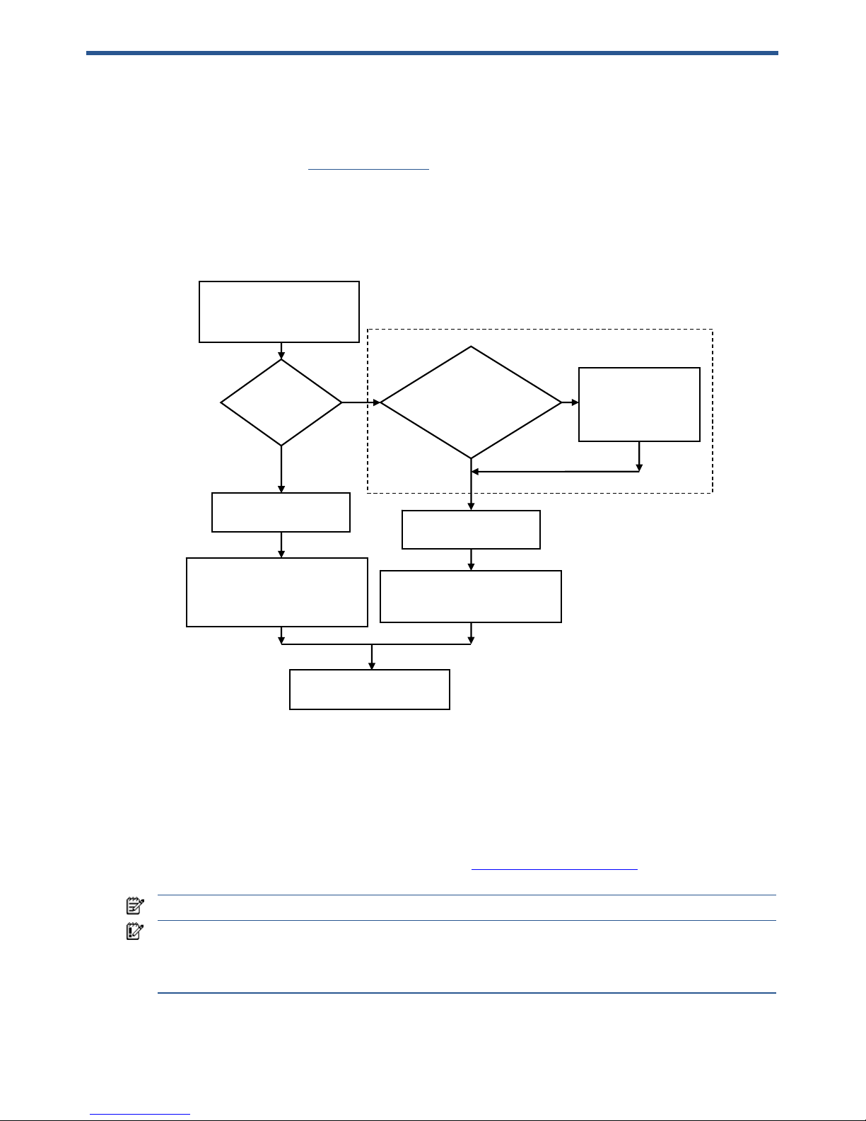
Capturing a blade workstation image using HP RDP 52
8 Capturing a blade workstation image using HP RDP
HP Rapid Deployment Pack (HP RDP) can be used to capture the OS image of the blade workstation for both
Windows XP-32 and Windows XP-64. This chapter assumes you are familiar with HP RDP—for detailed
information on HP RDP, visit www.hp.com/go/rdp
.
The flowchart in Figure 8-1 provides an overview of the process used to capture the OS image. The first flowchart
branch depends on whether you plan to use Altiris to run Sysprep, or if you plan to run Sysprep manually.
Following the flowchart, the details of each step are presented.
Figure 8-1 Process to capture the blade workstation OS image
STEP 1: Configure the blade workstation (reference computer) whose image is to be captured
Perform the following steps to prepare the blade workstation whose image is to be captured:
a. Install, update, and configure the OS—Ensure that the OS is configured as desired, including updates
and patches.
b. Change Remote Console Mode—If you need to view the capture process using the iLO 2 Remote
Console or the Local I/O Connector of the blade workstation, Remote Console Mode must be set to
Admin Mode or Setup Mode. See Section 2-1, “Setting Remote Console Mode
,“ for information on
setting Admin Mode or Setup Mode.
NOTE: HP RDP contains jobs that can be used to automatically set Remote Console Mode to the desired state.
IMPORTANT: Setting Remote Console Mode to Admin Mode or Setup Mode is not required for capturing an
image—it simply allows you to view the capture process using iLO 2. If Remote Console Mode is in User
Mode, you won’t be able to view the Windows desktop until after the image is captured, and you use RGS or
Remote Desktop Connection to log into the blade workstation.
If you do set Remote Console Mode to Admin Mode or Setup Mode, you’ll need to change the mode
back to User Mode after the image is captured.
STEP 1:
Configure the
blade workstation whose
image will be captured
Using
Altiris to run
Sysprep
?
Y
Does the
Altiris Deployment
Server need to be
configured to run
Sysprep
?
Configure the
Altiris Deployment
Server to run
Sysprep
N, Sysprep
will be run
manually
N
Y
STEP 3:
Configure
the A-client
STEP 4:
Create an Altiris job
to capture the image that
uses Altiris to run Sysprep
STEP 7:
Capture the
OS image using Altiris
STEP 2
STEP 5:
Run Sysprep
manually
This step will include running of Sysprep by
Altiris if STEPS 2-4 have been performed.
STEP 6:
Create an Altiris job
to capture the image that
doesn’t use Altiris to run
Sysprep
Page 53

Capturing a blade workstation image using HP RDP 53
To capture an OS image and deploy it to multiple other computers, the Sysprep tool needs to be run to set a new
SID and to apply new system settings, such as the computer name. If you plan to use Altiris Deployment Server to
run Sysprep, continue with STEP 2 below. If you plan to run Sysprep manually, proceed to STEP 5.
STEP 2: If required, configure the Altiris Deployment Server to run Sysprep
Depending on your RDP configuration, this step may have already been completed. To configure the Altiris
Deployment Server to run Sysprep, refer to the Deployment Solution documentation available from Altiris at
www.altiris.com
.
STEP 3: Configure the A-Client (Altiris Agent) so that it is installed on the blade workstation
If you are using Altiris to run Sysprep, you’ll need to configure the A-client (Altiris Agent) so that it is installed on
the blade workstation by performing these steps:
a. On the Altiris Deployment Server, click Tools
→
Remote Agent Installer. The Remote Agent Installer
screen displays. Select “Use this username and password for client/s”. (Use an Administrative account
local to target), Click Next.
b. Accept the default install directory path or choose your own, and select “Enable this agent to use
SIDgen and/or Microsoft Sysprep”.
c. If you wish to configure optional settings on the A-client, click the “Change Settings” button. When
done click “next”.
d. Click the dropdown arrow and select Use only Microsoft Sysprep utility. Locate the DEPLOY.cab file
you downloaded in STEP 2, and in the XP/2003 box using the browse button next to “Windows
XP/2003”. Click “Next”.
e. Select “Add client(s) to default group”, or select the group you would like them to be added to.
f. On the “Selecting Clients” screen, select or add the Names or IP address of the blade workstations you
wish to install A-client(s) on by using the “Add” button. You can select multiple workstations at a time.
When finished adding workstations, select finish, and it will show the progress and results of the Altiris
Agent installation.
STEP 4: Create a job that captures the image using Altiris to run Sysprep
Perform the following steps to create a new job that captures the OS image using Altiris to run Sysprep:
a. Under the jobs pane, right-click in the white area and select “New Job”. Enter a name for the job that is
unique. Double click the new job, Click “Add>>” and select “Create Disk Image”.
b. On the “Save Disk Image to a file” screen, next to the name field click the browse button and locate the
images folder (<Express Share>\Images) and enter a unique image name for your image. Click Save.
c. Select “Prepare using Sysprep” and enter the Product key to be used. If you have a specific pre-boot
environment you want to run the image in, select it at the bottom of the screen, in the case of the
Windows Blade the default should be WinPE.
d. Accept the defaults on the “Return Codes” screen.
Continue with STEP 7.
Page 54

Capturing a blade workstation image using HP RDP 54
STEP 5: Run Sysprep manually
To run Sysprep manually, refer to the article How to use the Sysprep tool to automate successful deployment
of Windows XP, available at www.microsoft.com/kb/302577
. If you run Sysprep manually, you’ll need to
run it, shut down the computer, and boot directly to PXE manually (F12 on POST) to run the image process
without booting to the OS first.
STEP 6: Create an Altiris job to capture the image that doesn’t use Altiris to run Sysprep
To create an Altiris capture job that doesn’t run Sysprep, perform the following steps:
a. Under the jobs pane, right-click in the white area and select “New Job”. Enter a name for the job that is
unique. Double click the new job, Click “Add>>” and select “Create Disk Image”.
b. On the “Save Disk Image to a file” screen, next to the name field click the browse button and locate the
images folder (<Express Share>\Images) and enter a unique image name for your image. Click Save.
c. Click the “Advanced” button next to the pre-boot select. In the middle of the screen, you’ll see a “Do
not boot to production” selection. By selecting this, Altiris A-Client will not run the system image
preparation procedure that includes Sysprep. This selection should be used in two specific situations:
• If you are running Sysprep manually.
• If you are not using Sysprep at all, and simply want to make a carbon image of you computer.
d. Accept the defaults on the “Return Codes” screen.
STEP 7: Apply the new Altiris job to computers whose images you are capturing
a. Now that your new Job is created, you can drag and drop that job to computers in the HP RDP
console.
b. By selecting the computer in the “Computers” pane of the Altiris Console in the right pane, you will see
all running jobs and their status.
Page 55
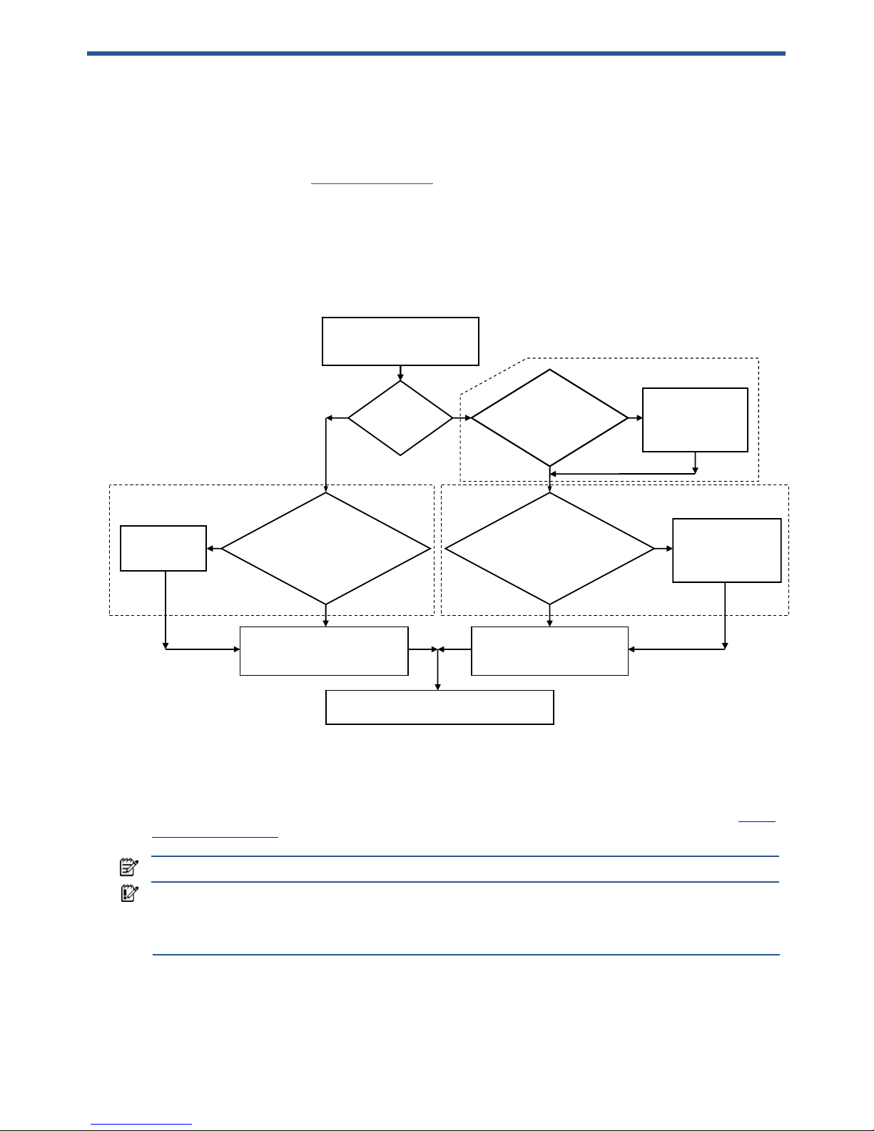
Deploying a blade workstation image using HP RDP 55
9 Deploying a blade workstation image using HP RDP
HP Rapid Deployment Pack (HP RDP) can be used to deploy an OS image to the blade workstation for both
Windows XP-32 and Windows XP-64. This chapter assumes you are familiar with HP RDP—for detailed
information on HP RDP, visit www.hp.com/go/rdp
. This chapter also assumes you have an existing blade
workstation image ready to deploy.
The flowchart in Figure 9-1 provides an overview of the process used to deploy an OS image. The first flowchart
branch depends on whether you plan to use Altiris to run Sysprep, or if you plan to run Sysprep manually.
Following the flowchart, the details of each step are presented.
Figure 9-1 Process to deploy an OS image to the blade workstation
STEP 1: If needed, change Remote Console Mode
If you need to view the deployment process using the iLO 2 Remote Console or the Local I/O Connector of the
blade workstation, Remote Console Mode must be set to Admin Mode or Setup Mode. See Section 2-1, “Setting
Remote Console Mode,“ for information on setting Admin Mode or Setup Mode.
NOTE: HP RDP contains jobs that can be used to automatically set Remote Console Mode to the desired state.
IMPORTANT: Setting Remote Console Mode to Admin Mode or Setup Mode is not required for deploying an
image—it simply allows you to view the deployment process using iLO 2. If Remote Console Mode is kept in
User Mode, you will not be able to view the Windows desktop until after the image is deployed, and you use
RGS or Remote Desktop Connection to log into the blade workstation.
If you do set Remote Console Mode to Admin Mode or Setup Mode, you’ll need to change the mode back to
User Mode after the image is deployed.
STEP 1:
Change Remote
Console Mode if you need to
view the deployment process
N
Using
Altiris to run
Sysprep
?
Y
Does the
Altiris Deployment
Server need to be
configured to run
Sysprep
?
Configure the
Altiris Deployment
Server to run
Sysprep
N
Y
STEP 2
Do you
have an OS
installed? If so, do you
want to install A-client to automate
the computer shutdown
and PXE boot
?
Install A-client on
desired computers,
including Sy sprep
step
N
Y
Install A-client
on desir e d
computers
STEP 6:
Create an Altiris job to
deploy the image that doesn’t
use Altiris to run Sysprep
STEP 4:
Create an Altiris job
to deploy the image that
uses Altiris to run Sysprep
Do you
have an OS
installed? If so, do you
want to install A-client to automate
the computer shutdown
and PXE boot
?
Y
N
STEP 3
STEP 5
STEP 7:
Deploy the OS image using Altiris.
Thi s step may require a manua l PXE bo ot
To perform a manual PXE boot, press
F12 key during Power-on Self Test.
Running Syspre p dur in g
an OS deploy requires
that Sysprep has already
been run durin g t he OS
capture.
If Sysprep is run and if a Sysprep
answer file has been specified in
Altiris, no user-supplied information
will be required during STEP 7.
Page 56

Deploying a blade workstation image using HP RDP 56
STEP 2: If required, configure the Deployment Server to run Sysprep
Depending on your HP RDP configuration, this step may have already been completed. To configure the Altiris
Deployment Server to run Sysprep, refer to the Deployment Solution documentation available from Altiris at
www.altiris.com.
STEP 3: If needed, install A-Client (Altiris Agent) on the target computer (this agent will use Sysprep)
If the target computer currently has an OS installed, you can optionally install the Altiris A-client to automate the
system shutdown and PXE boot. If the target computer already has A-client installed, and is seen by the Altiris
deployment console, this step is not needed. To install the Altiris A-client, perform the following steps:
a. Click Tools
→
Remote Agent Installer. The Remote Agent Installer screen displays. Select “Use this
username and password for client/s”. (Use an Administrative account local to target), Click Next.
b. Accept the default install directory path or choose your own.
c. Because you are using Altiris to run sysprep, select “Enable this agent to use SIDgen and/or Microsoft
Sysprep”.
d. If you wish to configure option settings on the A-client, click the “Change Settings” button. When done
click “next”.
e. Click the dropdown arrow and select Use only Microsoft Sysprep utility
. Locate the DEPLOY.cab file
you downloaded in step 2, and in the XP/2003 box using the browse button next to “Windows
XP/2003”. Click “Next”.
f. Select “Add client(s) to default group”, or select the group you would like them to be added to.
g. On the “Selecting Clients” screen, select or add the Names or IP address of the workstation(s) you wish
to install A-client(s) to using the “Add” button, you can select multiple at a time. When finished adding
systems, select finish, and it will show the progress and results of the installation.
STEP 4: Create a new job (that uses Altiris to run Sysprep) to deploy the OS image
Perform the following steps to create a new job that deploys the OS using Altiris to run Sysprep:
a. Under the jobs pane, right-click in the white area and select “New Job”. Enter a name for the job that is
unique. Double click the new job, Click “Add>>” and select “Distribute Disk Image”.
b. On the first screen, use the browse button next to the “name” field to locate the image file you with to
use. This file must be located on the Altiris express share or a location manually mapped for Altiris and
pre-boot environment to use.
c. Select “Prepared Using Sysprep”. Add the appropriate operating system and Key.
d. To specify the Sysprep answer file, select “advanced”. Select “Use default answer file” to use the Altiris
default file (this can be modified), or “Use the following answer file” to enter your own.
e. Select the appropriate boot environment. Click Next. Accept the defaults. Click Finish.
Continue with STEP 7.
STEP 5: If needed, install A-Client (Altiris Agent) on the target computer (this agent will not use Sysprep)
If the target computer currently has an OS installed, you can optionally install the Altiris A-client to automate the
system shutdown and PXE boot. If the target computer already has A-client installed, and is seen by the Altiris
deployment console, this step is not needed. To install the Altiris A-client, perform the following steps:
a. Click Tools
→
Remote Agent Installer. The Remote Agent Installer screen displays. Select “Use this
username and password for client/s”. (Use an Administrative account local to target), Click Next.
b. Accept the default install directory path or choose your own.
c. If you wish to configure option settings on the A-client, click the “Change Settings” button. When done
click “next”.
d. Select “Add client(s) to default group”, or select the group you would like them to be added to.
e. On the “Selecting Clients” screen, select or add the Names or IP address of the workstation(s) you wish
to install A-client(s) to using the “Add” button, you can select multiple at a time. When finished adding
systems, select finish, and it will show the progress and results of the installation.
Page 57

Deploying a blade workstation image using HP RDP 57
STEP 6: Create a new job (that doesn’t use Altiris to run Sysprep) to deploy the image
Perform the following steps to create a new job that deploys the OS; but doesn’t use Altiris to run Sysprep:
a. Under the jobs pane, right-click in the white area and select “New Job”. Enter a name for the job that is
unique. Double click the new job, Click “Add>>” and select “Distribute Disk Image”.
b. On the first screen, use the browse button next to the “name” field to locate the image file you with to
use. This file must be located on the Altiris express share or a location manually mapped for Altiris and
pre-boot environment to use.
c. Select the appropriate boot environment. Click Next. Accept the defaults. Click Finish.
STEP 7: Deploy the OS using the new Altiris job
This step may require a manual PXE boot, depending on whether you’ve configured the Altiris A-client to
automate computer shutdown and PXE boot. To perform a manual PXE boot, press F12 key during Power-on Self
Test.
a. Now that your new job is created, you can drag and drop that job to computers in the HP RDP
console.
b. By selecting the computer in the “Computers” pane of the Altiris Console in the right pane, you can
view the job and its status.
Page 58

Performing an unattended installation of Windows XP-32 and Windows XP-64 58
10 Performing an unattended installation of Windows
XP-32 and Windows XP-64
This chapter provides an overview of the steps to perform an unattended installation of Windows XP-32 and
Windows XP-64. This chapter does not detail all steps needed to create and configure an unattended installation
environment; rather, it demonstrates the essential elements that are specific to blade workstations.
10-1 Assumptions
This chapter assumes you have a basic knowledge of the Microsoft Windows XP unattended installation process.
The following topics are not covered in this chapter:
• Unattended installation concepts
• Creating and configuring source distribution files
• Slipstreaming updates and patches
• Boot disks
• Networking
• Creating unattend.txt files.
This document also assumes that a distribution server is already configured, working, and contains source install
files needed for the operating systems of interest, e.g. Windows XP-64. For further information on the subjects
not covered in this chapter, please refer to the appropriate Microsoft documentation.
Page 59
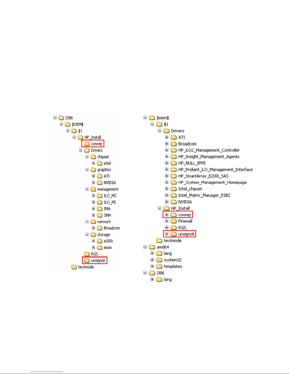
Performing an unattended installation of Windows XP-32 and Windows XP-64 59
10-2 Unattended installation procedure
This section describes the steps to perform an unattended installation of Windows XP-32 and Windows XP-64.
1. Create and update the remote install distribution share.
2. In the distribution share, create a directory structure to store the OS installation files as well as the HP-
specific drivers and software for the blade workstation. Example directories are shown in Figure 10-1 (the
highlighted directories are discussed in step 3).
a. Windows XP Pro SP2—The $OEM$ folder is created under the i386 directory, which was originally
created manually or via Remote Installation Service.
b. Windows XP Pro x64—The amd64 and i386 subdirectories contain the OS files, and the $OEM$
folder needs to be on the same level as amd64 and i386
Figure 10-1 Example unattended installation directories
Windows XP Pro SP2
Windows XP Pro x64
Page 60
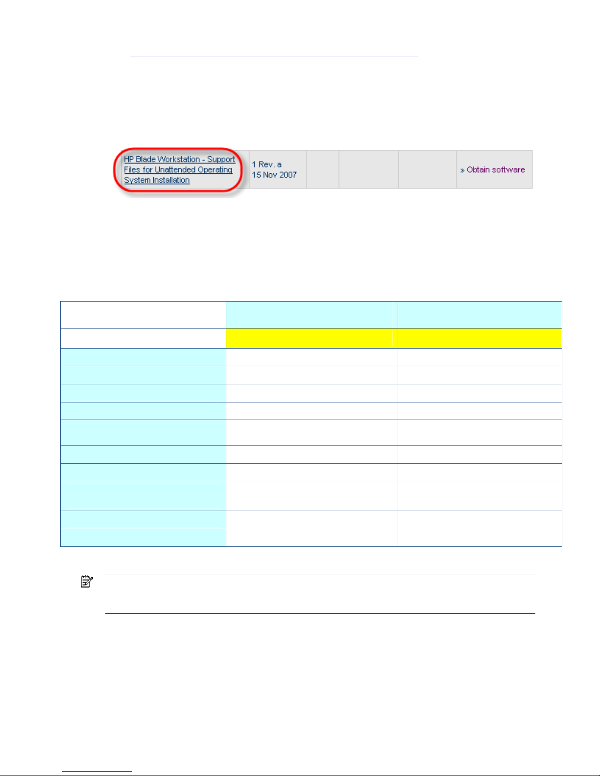
Performing an unattended installation of Windows XP-32 and Windows XP-64 60
3. In this step, the software and drivers required for unattended installation are downloaded. Refer to
“APPENDIX A: Downloading and installing SoftPaqs and Smart Components
,” for information on
downloading and unpacking SoftPaqs and Smart Components.
a. Download the SoftPaq shown in Figure 10-2—This SoftPaq contains the “conrep” folder and the files
used to change Remote Console Mode. The SoftPaq also contains the unsigned folder and files that
contain the “UnsignOK.exe” utility to bypass unsigned driver pop-up windows during the unattended
installation.
Figure 10-2 SoftPaq that provides support files for unattended installation of Windows
b. Uncompress the above SoftPaq and copy the folder and contents of the “conrep” and “unsignok”
folders to the “$OEM$\$1\HP_Install” directory, as highlighted in Figure 10-1.
c. Download the latest drivers and software for the blade workstation using the process described in
Appendix A. Unpack and copy the drivers and software into the appropriate subdirectories in the
distribution share. Examples of unpacked drivers and software are listed in Table 10-1.
Table 10-1 Example drivers and software
Windows XP Pro SP2
example directory
Windows XP Pro x64
example directory
ROOT : $OEM$\$1\HP_Install\Drivers\... ROOT : $OEM$\$1\Drivers
ATI graphics driver
graphics\ATI ATI
nVidia graphics driver
graphics\NVIDIA NVIDIA
iLO Management Controller Driver
management\ILO_MC HP_iLO2_Management_Controller
iLO Management Interface Driver
management\ILO_MI HP_Proliant_iLO_Management_Interface
HP System Management
HomePage
management\IMA HP_System_Management_Homepage
Insight Management Agents
management\SMH HP_Insight_Management_Agents
Broadcom NIC Driver
network\Broadcom Broadcom
SmartArray E200i Storage
Controller Driver
storage\e200i,
$OEM$\textmode (see NOTE below)
$OEM$\textmode
Intel Chipset Driver
Intel_chipset
Intel ESB2 Driver
Intel_Matrix_Manager_ESB2
NOTE: For Windows XP-32, the SmartArray E200i storage controller driver must be unpacked and copied
into the “$OEM$\$1\HP_Install\Driver\storage\e200i“ directory as well as the “$OEM$\textmode”
directory. If this driver is not stored in both locations, the install will fail.
Page 61

Performing an unattended installation of Windows XP-32 and Windows XP-64 61
d. Copy RGS and additional utilities in various distribution sub-folders
Table 10-2 RGS and utilities
Windows XP Pro SP2
example directory
Windows XP Pro x64
example directory
ROOT : $OEM$\$1\HP_Install\ ROOT : $OEM$\$1\HP_Install\...
RGS
RGS RGS
Conrep (BIOS setting utility)
conrep conrep
unsignOK
unsignok unsignok
Firewall 'punching script'
Firewall
NOTE: For more information on creating the RGS answer file, refer to the RGS User Guide.
4. Create regedit command files in the ‘$OEM$\$1\HP_Install” directory to change registry settings for RGS
to work properly.
CAUTION: The following registry modifications are given as examples only. Editing the registry can
cause serious problems with Windows. Although these examples have been shown to work, using these
examples is at your own risk.
a. Turn off Fast User Switching—In this example, Fast User Switching is turned off by a script file called
“FastUserSwitching.reg”, which contains the following lines:
[HKEY_LOCAL_MACHINE\SOFTWARE\Microsoft\Windows NT\CurrentVersion\Winlogon]
"AllowMultipleTSSessions"=dword:00000000
"LogonType"=dword:00000000
Where:
LogonType—Set to 0 to display the security dialog box, set to 1 to display the new Welcome
screen.
AllowMultipleTSSessions—Set to 0 to disable fast user switching, set to 1 to allow
switching.
b. Turn off Simple File Sharing—In this example, Simple File Sharing is turned off by a script called
“Simple File Sharing.reg” with the following lines:
[HKEY_LOCAL_MACHINE\SYSTEM\CurrentControlSet\Control\Lsa]
"forceguest"=dword:00000000
Where:
forceguest—Se
t to 0 to disable and turn off simple file sharing, set to 1 to turn on simple file
sharing.
Page 62

Performing an unattended installation of Windows XP-32 and Windows XP-64 62
5. Next, add blade workstation-specific entries to the different sections of the unattended answer file, either
unattend.txt or ristndrd.sif (for RIS installation). The following entries are based on the example directories
created in step 2, and will need to be adapted to your configuration if it differs from the directories shown
in step 2.
NOTE: See Microsoft documentation for additional details on the creation of the unattended.txt file.
a. Windows XP Pro SP2
• Add to the [Unattended] section
Plug and Play driver location:
OemPNPDriversPath=\textmode;HP_Install\Drivers\chipset\intel;HP_In
stall\Drivers\graphics\ati;HP_Install\Drivers\Management\IMA;HP_In
stall\Drivers\Management\ILO_MC;HP_Install\Drivers\Management\ILO_
MI;HP_Install\Drivers\network\Broadcom
Other settings:
OemPreinstall=Yes
DisableVirtualOemDevices=Yes
DriverSigningPolicy=Yes
• Add to the [MassStorageDrivers] section
[MassStorageDrivers]
"Windows 2000 Driver for Smart Array E200 and E200i
Controllers"=OEM
• Add to the [OEMBootFiles] section
[OEMBootFiles]
CISSm2.sys
HpCISSx2.inf
HpCISSm2.cat
txtsetup.oem
• Add to the [GuiUnattended] section
[GuiUnattended]
AutoLogonCount=2
• Add to the [NetOptionalComponents] section
[NetOptionalComponents]
SNMP = 1
NOTE: The above entry installs SNMP during setup. This is required in order for the management agents to
install.
• Add to the [GuiRunOnce] section
[GuiRunOnce]
"%systemdrive%\HP_Install\Driver_Software_Install2.cmd"
The above entry will run the install script “Driver_Software_Install.cmd” (see Appendices) that will
install drivers and software at first login after install.
• Add to the [WindowsFirewall] section
[WindowsFirewall]
Profiles = WindowsFirewall.TurnOffFirewall
[WindowsFirewall.TurnOffFirewall]
Mode = 0
In the above firewall example, the Windows firewall is disabled (refer to Windows documentation on
firewall settings). In practice, it is not recommended to disable the Windows firewall unless another
firewall is in use. Refer to Section 4-2-4, “Configuring the operating system
,” for recommended firewall
settings.
Page 63

Performing an unattended installation of Windows XP-32 and Windows XP-64 63
b. Windows XP Pro x64
• Add to the [Unattended] section
Plug and Play driver location:
OemPNPDriversPath="\\%SERVERNAME%\RemInst\%INSTALLPATH%\$OEM$\text
mode;Drivers\HP_NULL_IPMI;Drivers\HP_SmartArray_E200i_SAS;Drivers\
Intel_chipset;Drivers\ "
IMPORTANT: For both Windows XP-32 and Windows XP-64, the path for the NVIDIA driver is intentionally
omitted. Because the blade workstation contains two video controllers, the workstation will make the NVIDIA
driver primary during the install and the screens will go black if Remote Console Mode is in Setup Mode. This
is because the iLO Remote Console and Local I/O Connector displays are controlled by the ATI controller
and will be deactivated if NVIDIA is the primary controller. The NVIDIA driver is installed later in the
installation process and activated before switching to User Mode.
IMPORTANT: The ATI drivers that are downloadable from the blade workstation software and drivers web
page are not Microsoft signed. It is your decision to download and install the unsigned drivers. If you decide
not to use the unsigned drivers, the default VGA driver in the operating system will be loaded. Remove the
ATI lines in the driver path to prevent the ATI driver from loading.
Other settings:
OemPreinstall=Yes
DisableVirtualOemDevices=Yes
DriverSigningPolicy=Yes
• Add to the [MassStorageDrivers] section
[MassStorageDrivers]
"Windows Driver for Smart Array SAS/SATA Controllers"="OEM"
• Add to the [OEMBootFiles] sections
[OEMBootFiles]
txtsetup.oem
hpcisss2.cat
hpcisss2.sys
hpcissx2.inf
• Add to the [GuiUnattended] section
[GuiUnattended]
AutoLogonCount=2
• Add to the [NetOptionalComponents] section
[NetOptionalComponents]
SNMP = 1
NOTE: The above entry installs SNMP during setup. This must be done or the management agents will not
install correctly.
• Add to the [GuiRunOnce] section
[GuiRunOnce]
"%systemdrive%\HP_Install\Driver_Software_Install2.cmd"
The above entry will run the install script “Driver_Software_Install.cmd” (see Appendices) that will
install drivers and software at first login after install.
Page 64

Performing an unattended installation of Windows XP-32 and Windows XP-64 64
• Add to the [WindowsFirewall] section
[WindowsFirewall]
Profiles = WindowsFirewall.TurnOffFirewall
[WindowsFirewall.TurnOffFirewall]
Mode = 0
In the above firewall example, the Windows firewall is disabled (refer to Windows documentation
on firewall settings). In practice, it is not recommended to disable the Windows firewall unless
another firewall is in use. See Section 4-2-4, “Configuring the operating system
,“ for recommended
firewall settings.
• Optional [NetAdapters] sections—To insure the network card is enumerated correctly, specifically
state them in the unattended file. For example:
[NetAdapters]
Adapter01=Params.Adapter01
Adapter02=Params.Adapter02
[Params.Adapter01]
InfID="b06bdrv\l2nd&pci_164c14e4"
PciBusNumber = 3
PciDeviceNumber = 0
PciFunctionNumber = 0
ConnectionName = "HP NC373i Multifunction Gigabit Server Adapter #1"
[Params.Adapter02]
InfID="b06bdrv\l2nd&pci_164c14e4"
PciBusNumber = 7
PciDeviceNumber = 0
PciFunctionNumber = 0
ConnectionName = "HP NC373i Multifunction Gigabit Server Adapter #2"
6. Using a RIS server—If you are using Microsoft RIS (Remote Installation Services), you’ll need to add network
drivers to the i386 (Windows XP Pro SP2) or amd64 (Windows XP Pro 64 SP2) subdirectories. Go to:
h18023.www1.hp.com/support/files/server/us/download/27418.html
Download the HP NC-Series Multifunction Drivers for RIS/WinPE. For example, for Windows XP-64, the
b06nd.inf and b06nd51a.sys files are needed for RIS. Add the files and restart RIS.
7. Connect the target blade workstation to the distribution share per your unattended remote installation
process, such as boot floppy, RIS, HP RDP or Altiris.
Page 65

Performing an unattended installation of Windows XP-32 and Windows XP-64 65
Example Windows XP Pro GuiRunOnce script
The GuiRunOnce script installs the needed software and drivers in the proper order, and runs after the first boot. A sample
version of this script is included in the “HP Blade Workstation Unattended install support Files” downloaded earlier in step
3a. This script runs after first boot. Create the following script and name it “Driver_Software_Install.cmd” and copy it to
“$OEM$\$1\HP_Install” directory (see [GuiRunOnce], step 5e). Modify as needed.
rem @echo off
title HP Driver and Software Install Script
rem Starting - Change Registry Entree for RGS
regedt32.exe /s %systemdrive%\HP_Install\forceguest.reg
regedt32.exe /s %systemdrive%\HP_Install\FastUserSwitching.reg
rem Complete - Change Registry Entree for RGS
rem Starting XPUnsignOK2.exe to automatically push accept button for Unsigned ATI driver
echo.
echo Starting XPUnsignOK2.exe
start %systemdrive%\HP_Install\unsignok\XPUnsignOK2.exe
echo XPUnsignOK2.exe Started
rem Starting ATI driver install
echo.
echo Starting ATI driver install
cd %systemdrive%\HP_Install\Drivers\graphics\ATI
cpqsetup.exe /s
rem Completed ATI driver install
rem Starting NVIDIA driver install
echo.
echo Starting NVIDIA driver install
cd %systemdrive%\HP_Install\Drivers\graphics\nvidia
setup.exe -s -i
rem Completed NVIDIA driver install
echo Installing RGS
cd %systemdrive%\HP_Install\RGS\
setup.exe /s /f1"%systemdrive%\HP_Install\RGS\ReceiverInstall.iss"
echo Completed Installing RGS
rem Starting Management Agent install
echo.
echo Starting Management Agent install
cd %systemdrive%\HP_Install\Drivers\management\IMA
agents_32.msi /quiet
rem Completed Management Agent install
rem Starting Management Homepage install
echo.
echo Starting Management Homepage install
cd %systemdrive%\HP_Install\Drivers\management\SMH
sp36105.exe /s
rem Completed Management Homepage install
rem Changing to USER mode, next reboot)
rem Options on this command includes :
rem -fsetup.dat : change system to setup mode
rem -fuser.dat : change to user mode
rem - fadmin.dat : change system to admin mode
echo.
echo Starting Management Homepage install
cd %systemdrive%\HP_Install\conrep
conrep.exe -l -fuser.dat -xconrep.xml
rem Completed Changing to USER mode, next reboot
echo.
echo HP Install Script Complete
echo.
echo Init Reboot
start shutdown -r -t 30
exit
Page 66

Performing an unattended installation of Windows XP-32 and Windows XP-64 66
Example Windows XP Pro 64 GuiRunOnce script
rem @echo off
title HP Driver and Software Install Script
rem Starting XPUnsignOK2.exe to automatically push accept button for Unsigned ATI driver
echo.
echo Starting XPUnsignOK2.exe
start %systemdrive%\HP_Install\unsignok\XPUnsignOK2.exe
echo XPUnsignOK2.exe Started
rem Complete XPUnsignOK2.exe to automatically push accept button for Unsigned ATI driver
rem Starting ATI driver install
echo.
echo Starting ATI driver install
cd %systemdrive%\Drivers\ATI
cpqsetup.exe /s
rem Completed ATI driver install
rem Starting NVIDIA driver install
echo.
echo Starting NVIDIA driver install
cd %systemdrive%\Drivers\NVIDIA
setup.exe -h"1024" -v"768" -b"24" -j"60" -s
rem Completed NVIDIA driver install
rem Starting Broadcom driver install
echo.
echo Starting Broadcom driver install
cd %systemdrive%\Drivers\Broadcom
cpqsetup.exe /s
rem Completed Broadcom driver install
rem Starting Management Agent install
echo.
echo Starting Management Agent install
cd %systemdrive%\Drivers\HP_Insight_Management_Agents
cpqsetup.exe /s
rem Completed Management Agent install
rem Starting HP Proliant iLO2 Management Controller install
echo.
echo HP Proliant iLO2 Management Controller install
cd %systemdrive%\Drivers\HP_iLO2_Management_Controller
cpqsetup.exe /s
rem Completed HP Proliant iLO2 Management Controller install
rem Starting HP Proliant iLO Management Interface install
echo.
echo Starting HP Proliant iLO Management Interface install
cd %systemdrive%\Drivers\HP_Proliant_iLO_Management_Interface
cpqsetup.exe /s
rem Completed HP Proliant iLO Management Interface install
rem Starting System Management Homepage install
echo.
echo Starting Management Homepage install
cd %systemdrive%\Drivers\HP_System_Management_Homepage
cpqsetup.exe /s
rem Completed Management Homepage install
rem Starting firewall.cmd to punch holes in firewall (see Appendix C in this whitepaper)
echo.
echo Starting firewall.cmd
start %systemdrive%\HP_Install\firewall\firewall.cmd
echo firewall.cmd Started
rem Complete firewall.cmd
rem Changing to USER mode, next reboot)
rem Options on this command includes :
rem -fsetup.dat : change system to setup mode
rem -fuser.dat : change to user mode
rem - fadmin.dat : change system to admin mode
echo.
echo Starting Management Homepage install
cd %systemdrive%\HP_Install\conrep
conrep.exe -l -fuser.dat -xconrep.xml
rem Completed Changing to USER mode, next reboot
shutdown -r -t 300 -f
echo.
echo HP Install Script Complete
exit
Page 67

Performing an unattended installation of Windows XP-32 and Windows XP-64 67
Example firewall punch holes script (firewall.cmd)
netsh firewall add portopening TCP 2381 "HP SMH Secure Web Server (TCP 2381)"
netsh firewall add portopening TCP 5988 "WBEM/WMI Mapper (TCP 5988)"
netsh firewall add portopening TCP 5989 "WBEM/WMI Mapper Secure (TCP 5989)"
netsh firewall add portopening TCP 22 "SSH port (TCP 22)"
netsh firewall add portopening TCP 161 "SNMP port 161 (TCP 161)"
netsh firewall add portopening TCP 162 "SNMP port 162 (TCP 162)"
netsh firewall add portopening TCP 53 "DNS (TCP/UDP 53)"
netsh firewall add portopening TCP 67 "DHCP Request (TCP 67)"
netsh firewall add portopening TCP 68 "DHCP Reply (TCP 68)"
netsh firewall add portopening TCP 69 "M-TFTP (TCP 69)"
netsh firewall add portopening TCP 80 "HTTP + ILO (TCP 80)"
netsh firewall add portopening TCP 126 "SNMP port 126 (TCP 126)"
netsh firewall add portopening TCP 137 "Netlogon SMB (TCP/UDP 137)"
netsh firewall add portopening TCP 401 "WOL (TCP 401)"
netsh firewall add portopening TCP 402 "RDP dep agents (TCP 402)"
netsh firewall add portopening TCP 636 "SSL LDAP (TCP 636)"
netsh firewall add portopening TCP 750 "Active Directory (TCP 750)"
netsh firewall add portopening TCP 751 "Active Directory (TCP 751)"
netsh firewall add portopening TCP 752 "Active Directory (TCP 752)"
netsh firewall add portopening TCP 753 "Active Directory (TCP 753)"
netsh firewall add portopening TCP 754 "Active Directory (TCP 754)"
netsh firewall add portopening TCP 1010 "PXEconfig (TCP 1010)"
netsh firewall add portopening TCP 1433 "SQL (TCP 1433)"
netsh firewall add portopening TCP 1500 "RPC (TCP 1500)"
netsh firewall add portopening TCP 1758 "TFTP (TCP 1758)"
netsh firewall add portopening TCP 1759 "TFTP (TCP 1759)"
netsh firewall add portopening TCP 2500 "RPC (TCP 2500)"
netsh firewall add portopening TCP 4011 "External DHCP PXE (TCP 4011)"
netsh firewall add portopening UDP 123 "SNTP (UDP 123)"
netsh firewall add portopening UDP 445 "SMB (UDP 445)"
netsh firewall add portopening TCP 53 "DNS (TCP 53)"
netsh firewall add portopening UDP 53 "DNS (UDP 53)"
netsh firewall add portopening TCP 135 "AeXNS+DCOM+SQL (TCP 135)"
netsh firewall add portopening UDP 135 "AeXNS+DCOM+SQL (UDP 135)"
netsh firewall add portopening TCP 88 "Kerberos (TCP 88)"
netsh firewall add portopening UDP 88 "Kerberos (UDP 88)"
netsh firewall add portopening TCP 389 "LDAP (TCP 389)"
netsh firewall add portopening UDP 389 "LDAP (UDP 389)"
netsh firewall set icmpsetting 8
Page 68

User Information 68
11 User Information
11-1 Introduction
This chapter is intended for the user of the HP Blade Workstation Solution and describes how to interact with the
blade workstation from the client computer. The following topics are included in this chapter:
• Powering on the blade workstation client
• Changing the behavior of RGS
• Connecting from the client to the blade
• Sending Ctrl+Alt+Del to the blade workstation
• Accessing blade workstation desktop windows
• Moving desktop windows between monitors
• Spanning multiple displays with a desktop window
• Maximizing a window to a single display
• Supported USB devices
• Synchronizing a PDA
• Adjusting audio volume on the client and blade
• Disconnecting the client from the blade workstations
• Reconnecting to disconnected sessions
NOTE: In the following sections, “you” refers to the user.
11-2 Powering on the HP blade workstation client
To power on the blade workstation client, press the power button on the blade front panel. The computer cycles
through a startup sequence in less than a minute and then displays either an Enterprise Directory authentication
window or the remote display control panel. If a Webmin administration screen appears, your client has not
been properly configured. Contact your administrator for assistance.
11-3 Changing the behavior of RGS
It is sometimes necessary to change the behavior of RGS. This is done using the RGS Receiver Control Panel, the
Remote Display Window Toolbar, or the Virtual KVM. The Receiver Control Panel allows you to change all
connections between a client and one or more blades. The Remote Display Window Toolbar controls only a
single connection. The Virtual KVM allows switching between connections in situations where you have more
display area on your blades than you have monitors on the client. For more information about configuring RGS,
see the HP Remote Graphics User’s Guide.
The RGS Receiver must be in Setup Mode (where keyboard and mouse input are directed to the RGS Receiver) to
access the RGS controls. When the RGS Receiver is in Setup Mode, the display fades to gray as a visual queue.
Setup Mode is activated by entering certain key sequences while the RGS Receiver window is selected. By
default, the key sequence to enter Setup Mode is press Shift, press Space, and release Space (or, more
simply, hold down the Shift key, then press and release the Space bar). Once in Setup Mode (while still
holding the Shift key), you can:
• Press the M key (Setup Mode + M) to bring up the Receiver Control Panel.
• Press the H key (Setup Mode + H) to bring up the Remote Display Window Toolbar.
• Press the Tab key to access the Virtual KVM.
If these key sequences don’t work, contact your administrator.
Page 69
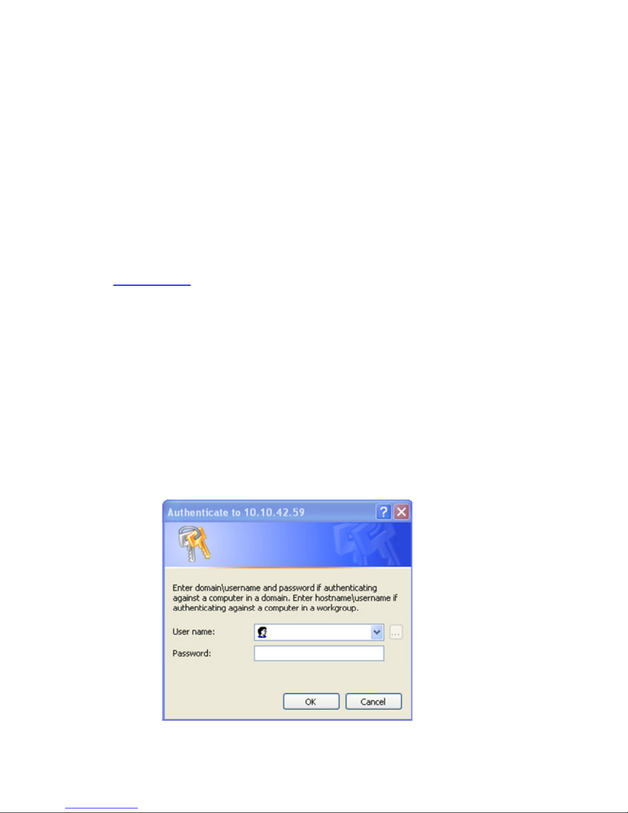
User Information 69
11-4 Connecting from the client to the blade
RGS connects the client computer to the blade workstation. Under typical circumstances, connecting to your
blade from the client computer is as simple as clicking the Connect button, or entering an IP address and clicking
Connect. However, RGS is a highly configurable product and your administrator can assign blade workstations
to the client in three ways:
• Enterprise Directory
• Local directory file
• Manual entry
The following sections describe the default behavior of RGS during the login process, and outline which
behaviors can be modified by your administrator. Contact your administrator if you are unsure which of the
following modes is used in your client environment.
11-4-1 Using Enterprise Directory
This section assumes that your organization has implemented an Enterprise Directory Service and your
administrator has assigned a blade workstation to you through this service. If this is not the case, contact your
administrator for the hostnames or IP addresses of the blades assigned to you, and then see Section 11-4-3,
“Using manual entry
.”
Default: If you are using Enterprise Directory, after powering up the client system, an Enterprise Directory
authentication window is displayed. Enter your user name and password in the indicated boxes, and click OK. In
many environments, you must provide a Microsoft Windows domain for authentication. In this case, enter
domain\username in the User Name box. For example, a user named “mhsmith” in the “Americas” domain
will enter Americas\mhsmith in the User Name box. If you are unsure whether domain authentication is used
at your site, contact your administrator.
After you enter your login information, the Windows login screen (from the blade) appears on the client display.
You can interact with the Windows screen in much the same way as a traditional PC or workstation.
Variation: If there are different user names set up on your assigned blade, click the General tab on the RGS
control panel and then select Prompt for username and password. This will allow different user names to be
entered for each blade, and each connection will be authenticated separately.
Variation: If your organization has implemented Single Sign-on with RGS, the only authentication prompt
(username and password) displayed is from the RGS Receiver on the client (see Figure 11-1). After authentication
by the RGS Receiver, the blade Windows desktop is displayed, logged-in and ready to use.
Figure 11-1 RGS Receiver Single Sign-on authentication prompt
Page 70
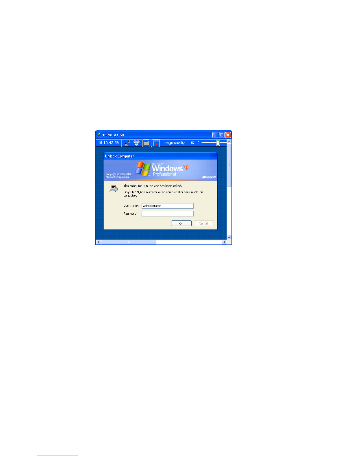
User Information 70
11-4-2 Using a local directory file
Setting up the Enterprise Directory may not be practical for smaller installations. Instead, it may be more efficient
to use a directory file that resides on the client. The directory file contains a list of systems assigned to authorized
users on that client. For details on the content of the directory file, see the HP Remote Graphics User’s Guide.
Default: You will be asked for your username and password twice for each blade—once from RGS to
authenticate the connection, and once by Windows for login authentication. Enter your user name and password
in the indicated boxes and click OK. In many environments, you must provide a Windows domain for RGS
connection authentication. In this case, enter domain\username in the User name box. For example, a user
named “mhsmith” in the “Americas” domain will enter Americas\mhsmith in the User name box. If you are
unsure whether domain authentication is used at your site, contact your administrator.
Variation: If the administrator has enabled RGS Easy Login, you’ll see only the standard Windows login screen
for each assigned blade (see Figure 11-2). Log into Windows as you normally would.
Figure 11-2 Blade Easy Login screen
Variation: If your organization has implemented Single Sign-on with RGS, the only authentication prompt
(username and password) displayed is from the RGS Receiver on the client, and it is displayed only once. After
authentication by the RGS Receiver, the blade Windows desktop is displayed, logged-in and ready to use.
11-4-3 Using manual entry
If the Enterprise Directory or the local directory file is not used at your site, you will need to manually enter the
name or IP address of your assigned blade. A local administrator can provide this information. Only a single
blade can be accessed from each client using manual entry.
Default: From the RGS control panel, enter the name or IP address of your assigned blade in the Hostname box.
Depending on how your local network is configured, the system name could be short (for example, “willard") or
long (for example, “willard.fc.hp.com”), or you might need to enter the IP address of your assigned blade (for
example, 10.10.24.145). Enter the name or address of the blade in the box and click Connect. If the system is
operational, you will see a connection authentication window with “Authenticate to <system name>” in the title
bar.
Enter your user name and password in the indicated boxes, and click OK. In many environments, you must
provide a Windows domain for authentication. In this case, enter domain\username in the User name box. For
example, a user named “mhsmith” in the “Americas” domain will enter Americas\mhsmith in the User name
box. If you are unsure whether domain authentication is used at your site, contact your administrator.
After entering your login information, the Windows login screen (generated from the blade) appears on the client
display. You can interact with the Windows screen in much the same way as a traditional PC or workstation.
Variation: If the administrator has enabled Easy Login on the blade, there will be no RGS connection
authentication window. The Windows login or lock screen appears on the client. In this case, just log into
Windows as you normally would.
Page 71

User Information 71
Variation: If your organization has implemented Single Sign-on, the only authentication prompt (username and
password) displayed is from the RGS Receiver on the client. After authentication by the RGS Receiver, the blade
Windows desktop of the blade is displayed, logged-in and ready to use.
11-5 Sending Ctrl+Alt+Delete to the blade workstation
Microsoft Windows requires that you enter Ctrl+Alt+Delete to log in, to access the Windows Task Manager, or to
lock the desktop. If you are accessing a blade workstation from the following clients, the process is identical to a
desk side system—the Ctrl+Alt+Delete key sequence is forwarded directly to the blade:
• HP Blade Workstation Client
• HP dc72 Blade Workstation Client
• HP dc73 Blade Workstation Client
If you are using a client running Microsoft Windows, Ctrl+Alt+Delete is intercepted by Windows. When this
happens, the Microsoft Windows Security screen is generated by the client computer, not by the blade
workstation—click Cancel if this occurs. Open the RGS Remote Display Window Toolbar as described in Section
11-3, “Changing the behavior of RGS
”, and then click the Ctrl+Alt+Del button shown below:
You can also use the alternate sequence, Ctrl+Alt+End, from a Microsoft Windows client. If this sequence is
disabled in RGS, enable it as follows:
1. Open the RGS Control Panel (Setup Mode + M).
2. Click the Advanced button.
3. Click the Hotkeys tab.
4. Select Send CTRL-ALT-END key sequence as CTRL-ALT-DEL.
11-6 Accessing blade workstation desktop windows
If your client computer is configured with four monitors (see Section 3-1, “Setting up the client access device“),
you can have as many as four active desktop windows from four blade workstations displayed simultaneously at
full resolution on your client computer. Assuming your client computer has been properly configured, the mouse
pointer should move logically from one monitor to the next as if the display area is one large monitor. To access
the desktop of a particular blade workstation, move the mouse pointer to that desktop area.
If the aggregate display area of your blade workstations exceeds the display area provided by the monitors on
your desk (such that one blade display covers another), you can use the RGS Virtual KVM to bring forward the
desktop window from the desired blade as follows:
1. Enter Setup Mode as described in Section 11-3, “Changing the behavior of RGS
.”
2. Press the Tab key. A window appears on the desktop showing a thumbnail view of each desktop.
3. Use the Tab key to highlight the desired desktop, and release the Setup Mode key.
4. Alternatively, you can put the system in Setup Mode, and then press a number key corresponding to the
desired blade.
Page 72

User Information 72
11-7 Moving desktop windows between monitors
RGS allows you to move desktop windows to any part of the client screen space. If the desktop windows sent
from the blade workstation have borders, click the top border and drag the desktop to the desired location. If the
desktop windows do not have borders, perform the following steps to move a window:
1. Enter RGS Setup Mode.
2. While holding the system in Setup Mode (by default, continue to hold the Shift key down), click anywhere
on the desktop, and drag the window to the desired location.
3. Release the mouse button and Shift key.
To simplify the alignment of desktop windows with monitors, the RGS Receiver has a “snap” feature that performs
the alignment automatically when a desktop window is positioned close to the edge of a monitor. If the snap
feature is not working, bring up the Receiver Control Panel and click this button:
11-8 Spanning multiple displays with a desktop window
The blade workstation NVIDIA graphics adapter supports a large display area (up to 4x1280x1024). The client
computer automatically adjusts its display area to accommodate the blade desktop window, limited by the
number and resolution of the monitors. For example, you might want a single blade workstation desktop window
to span two client monitors, each with a 1280x1024 resolution, placed side-by-side. The process to size the
blade desktop window is the same as changing the display resolution on a traditional PC or workstation running
Windows XP:
1. Right-click in an open space in the blade workstation desktop window, and then select Properties.
2. Click the Settings tab.
3. Under the Settings tab, adjust the screen resolution slider to 2560x1024, and click OK.
The desktop window now spans two monitors. If the desktop window starts on the right-most monitor, move the
desktop window to the left-most monitor to view it in its entirety (see Section 11-7, “Moving desktop windows
between monitors”).
11-9 Maximizing a window to a single display
If the blade workstation desktop window is set to span multiple monitors, every window that you maximize within
the desktop window will also span multiple monitors. However, this behavior may not be desirable. The graphics
driver SoftPaq supplied by HP includes an NVIDIA tool, nView, that allows you to change the setting so a
maximized window fills only one monitor. To change the setting, perform the following steps:
1. Change resolution from 1600x1200 to 2560x1024
2. Identify monitors (should only show "1")
3. Go to Desktop Management tab: disable, and then enable
4. Go to Windows tab, identify monitors (should show only "1")
5. Save settings and exit nView.
6. Re-enter nView
7. Go to Windows tab, identify monitors (should show only "1")
8. Log out
9. Log in
10. Re-enter nView
11. Go to Windows tab, identify monitors (should shows "1a 1b")
Test the new setting by maximizing a window. If configured properly, the maximized window fills only one
monitor. nView supports other customizations in the Windows environment as described in the ForceWare
Graphics Driver nView Desktop Manager User’s Guide included with the NVIDIA graphics driver SoftPaq.
Page 73

User Information 73
11-10 Supported USB devices
RGS supports remote USB, which allows USB devices connected to the client computer to be remotely attached to
the blade workstation. Remote USB is described in the HP RGS User Guide available at
www.hp.com/support/rgs_manuals. This document also lists the client-attached USB devices which can be
attached to the RGS Sender (in this case, the blade workstation).
11-11 Synchronizing a PDA
The virtual USB port currently supports PDA synchronization operations. Before synchronizing a PDA, you must
first load your PDA synchronization software on one of your blades. Contact your administrator if the software
has not been loaded.
To synchronize your PDA:
1. Open the RGS Control Panel (Setup Mode + M).
2. Click the Advanced button.
3. Click the USB tab.
4. Select the Enable USB checkbox, and then select from the dropdown list the blade where the USB traffic will
be directed.
5. Attach the PDA cradle to one of the USB ports on the blade workstation client, then place the PDA in the
cradle.
6. Follow the PDA manufacturer instructions for synchronizing the PDA on a standard Microsoft Windows XP
desktop system.
11-12 Adjusting audio volume on the client and blade
The blade workstation solution provides three audio adjustments:
• Adjust volume on a specific blade—Use Microsoft Windows Control Panel (click Start > Control Panel >
Sounds and Audio Devices).When you adjust the audio volume on a blade using Windows Control Panel,
the Mute button in the Microsoft Windows XP volume control does not function.
• Adjust volume on multiple blades—Use the volume control and mute button on the RGS Control Panel.
Open the RGS Control Panel (Setup Mode + M). If you do not hear audio, click the Mute button, and then
move the volume slider (triangular wedge next to the mute button) to the right to increase to volume.
Adjusting the volume at the client affects all blades, and muting audio at the client mutes all audio from the
blades. This change is not shown on individual Microsoft Windows XP desktops.
You can also use the RGS Control Panel to select between stereo and monaural audio, and choose the
sound quality level, from Low (AM radio) to High (full CD-quality). From the RGS Control Panel, click the
Advanced button, and then click the Audio tab.
NOTE: Higher-quality and stereo sound increase network bandwidth usage.
• Adjust volume on the client desktop only—Right-click the client desktop to access the Audio Control Panel.
This method is useful for adjusting the volume on your headphones and muting speakers without changing
blade volume levels. Select the output port (front jack, rear jack, or speaker) with the left and right arrow
keys, and adjust the volume with the up and down arrow keys. Use the M key to mute a device.
NOTE: If you mute the primary speaker on the blade workstation client and then adjust the volume from the
RGS Control Panel, the speaker might not be muted. For this reason, HP recommends that you establish volume
settings on the blade workstation client and RGS Control Panel, and then manage the audio from the individual
blades using standard Windows tools.
Page 74
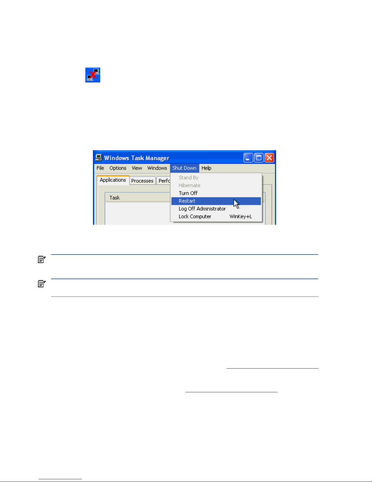
User Information 74
11-13 Disconnecting the client from the blade workstations
To disconnect a client from all blades, open the RGS Control Panel as described in Section 11-3 (Setup Mode +
M), and click the Disconnect button. To disconnect a client from an individual blade, open the Remote Display
Window Toolbar (Setup Mode + H), and click the Disconnect button shown below.
When you end a client RGS session, the blade workstation enters Disconnected mode. All blade workstation
processes continue to run, and the display state is maintained. Sessions are also disconnected when you log out
of Microsoft Windows on the blade workstation.
You can reboot the blade by clicking start>Shut Down. You can also reboot by pressing Ctrl+Alt+Del, and then
selecting Restart in the Task Manager (see Figure 11-3). Section 11-5 describes how to send Ctrl+Alt+Del to the
blade.
Figure 11-3 Rebooting Windows on the blade
During the reboot, the blade connection to the client is lost (there might be a small timeout lag). There is no
indication on the client when Windows starts up on the blade and the blade is available for login.
11-14 Reconnecting to disconnected sessions
If network connectivity is lost for more than a few seconds, or power to the client is interrupted, it is likely that the
RGS connection from the client to one or more blade desktop sessions will be lost. RGS keeps the Windows XP
sessions alive on the blade workstations (assuming they are still running).
Upon resumption of the network connection, open the RGS Control Panel on the client (Setup Mode + M), and
click the Connect button. All blades that were disconnected are re-connected at the state they were in when the
connection was lost. Follow the process described in Section 11-4, “Connecting from the client to the blade
,” to
log into the blade.
In case of a client power interruption, press the Power button when power is restored. Wait for the client to boot,
and then reconnect as described in Section 11-4, “Connecting from the client to the blade
.”
IMPORTANT: HP recommends that you not turn off the blade from the Windows XP desktop (for example, by
selecting Turn Off in the menu shown in Figure 11-3). Doing so would require administrator intervention to
restart the machine.
IMPORTANT: HP recommends that you not select a power-saving state (such as Standby or Hibernate). Doing
this would require administrator intervention to bring the system back online.
Page 75

Managing the blade workstation 75
12 Managing the blade workstation
This chapter describes how to manage blade workstations, and includes information on the following topics:
• Onboard Administrator
• Integrated Lights-Out 2 (iLO 2)
• Remote Desktop Connection
• System Management Homepage
• HP System Insight Manager (HP SIM)
• HP Rapid Deployment Pack
• HP Insight Diagnostics
• ROM-based Setup Utility
• BIOS programming
• Power-on Self Test (POST)
The blade workstation design is based on the design of the corresponding server blade, and most of the
manageability features are common between blade workstations and server blades. The following documents
contain information about the manageability of the systems:
• HP ProLiant BL460c Server Blade User Guide
• HP ProLiant BL2x220c Server Blade User Guide
• HP BladeSystem c7000 Enclosure Setup and Installation Guide
• HP BladeSystem c3000 Enclosure Setup and Installation Guide
• HP BladeSystem c3000 Tower Enclosure Setup and Installation Guide
• HP BladeSystem Onboard Administrator User Guide
• HP Integrated Lights-Out 2 User Guide
Page 76
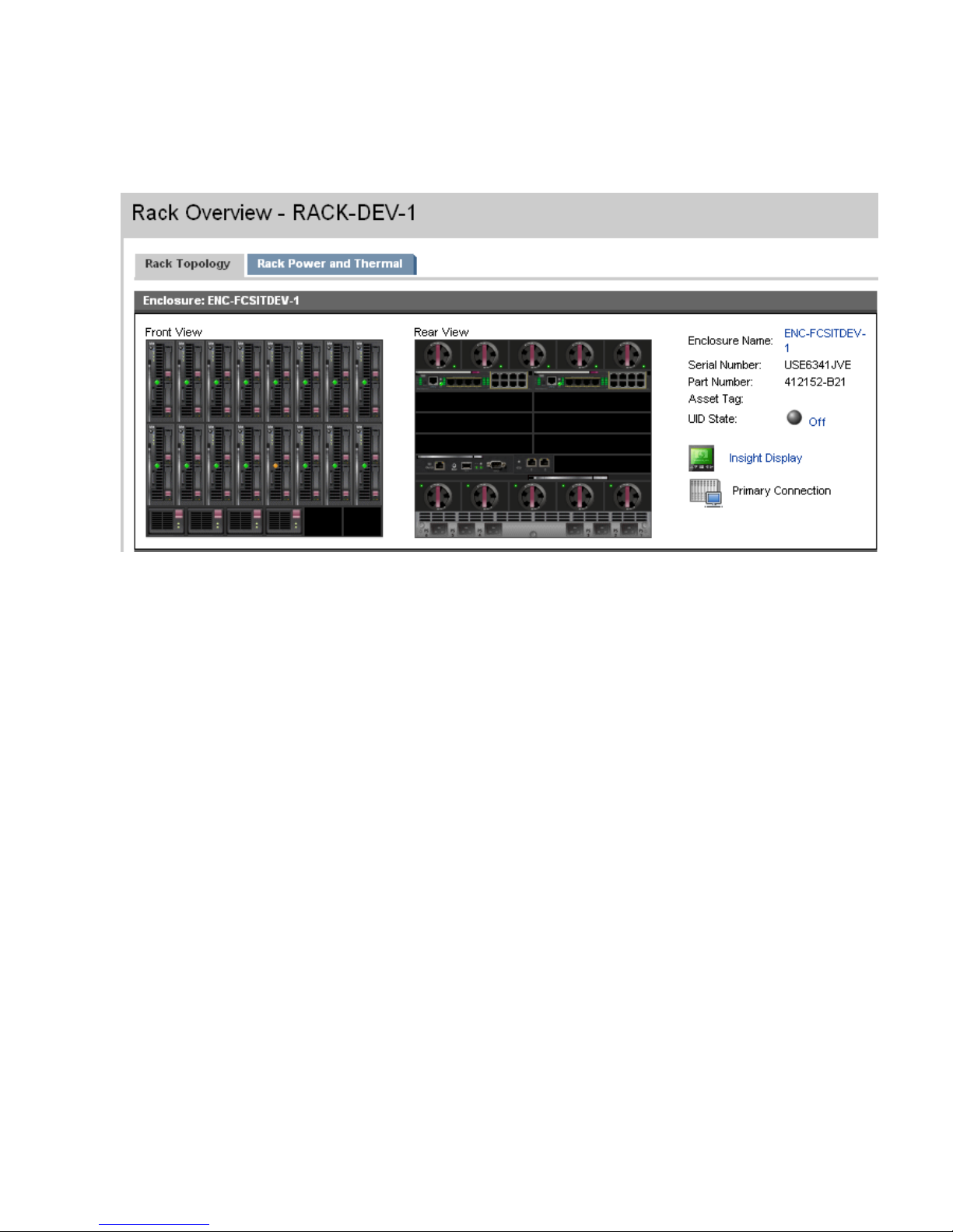
Managing the blade workstation 76
12-1 Onboard Administrator
The Onboard Administrator (OA) allows you to use a web browser to remotely log into OA and obtain detailed
information about the contents of each c7000 enclosure (see Figure 12-1).
Figure 12-1 Enclosure front and rear views
Using Figure 12-1, you can determine the following:
• A blade workstation is installed in each device bay.
• All blade workstations are powered on as indicated by the green lights.
• Four power supplies are installed in the enclosure.
• Two network interconnect devices are installed in the rear of the enclosure.
• One OA module is installed in the rear of the enclosure.
Page 77
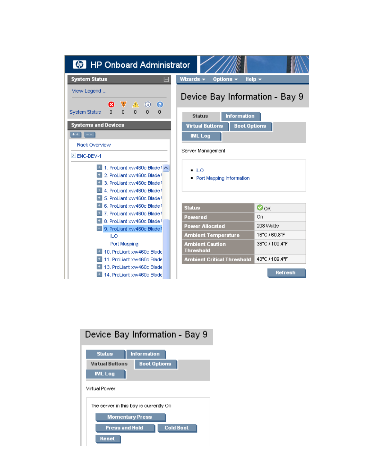
Managing the blade workstation 77
The OA also provides detailed information about each blade in the enclosure. In Figure 12-2, OA is providing
status information for blade 9.
Figure 12-2 Detailed blade information
As shown in Figure 12-3, OA enables remote management of the blades, including power management.
Figure 12-3 Blade power management
Page 78
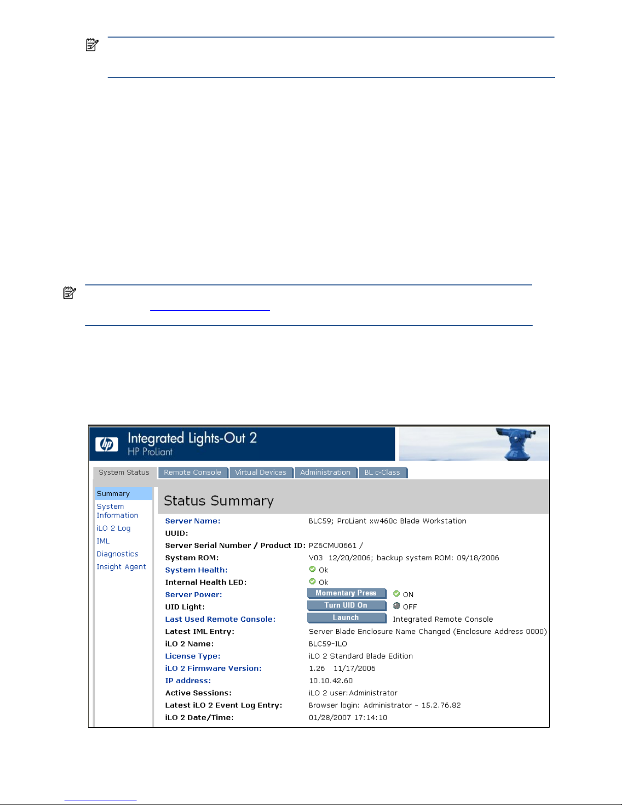
Managing the blade workstation 78
NOTE: The iLO 2 management processor also supports blade power management. However, using iLO 2
power management requires a separate login to iLO 2 on each blade. With OA, you can manage power for
all blades from a single OA login session.
All OA modules in the rack are linked together with Ethernet cables, allowing administrators to view and control
the blades in every enclosure by logging into the OA module in any enclosure. As described in the HP Blade
Workstation Solution Planning Guide, OA also includes the Insight Display, which enables administrators to
locally view and control the blades. For more information about OA capabilities, see the HP BladeSystem
Onboard Administrator User Guide.
12-2 Integrated Lights-Out 2 (iLO 2)
iLO 2 allows administrators to remotely perform most blade workstation management functions that otherwise
would require a visit to the blades. For example, iLO 2 allows administrators to remotely:
• Change BIOS settings
• View the boot process
• Validate that Windows starts up correctly (in Admin Mode and Setup Mode)
• Install software
12-2-1 Accessing iLO 2
The most common way to access iLO 2 is from a web browser pointed to the iLO 2 IP address (using HTTPS).
After logging into iLO 2, the status summary screen is displayed (see Figure 12-4).
Figure 12-4 iLO 2 status summary
IMPORTANT: Many iLO 2 capabilities require that Remote Console Mode is set to Admin Mode, as described
in Section 2-1, “Setting Remote Console Mode
.” In Admin Mode, the Windows desktop is viewable using iLO
2. In User Mode, the Windows desktop can only be viewed using RGS or Remote Desktop Connection.
Page 79
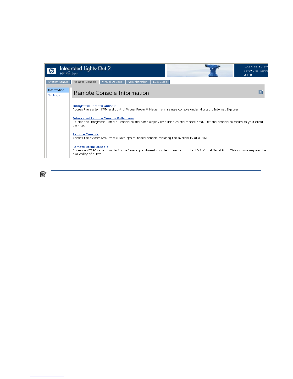
Managing the blade workstation 79
12-2-2 iLO 2 Remote Console
The iLO 2 Remote Console allows you to remotely view and interact with the boot console and the Windows
desktop (in Admin Mode and Setup Mode). To view the Remote Console types, select the Remote Console tab
(see Figure 12-5). For more information about each console type, see the HP Integrated Lights-Out 2 User Guide.
Figure 12-5 Remote Console selection
NOTE: The Remote Console capability of iLO 2 is not the same as the Remoter Console Mode BIOS setting.
Page 80
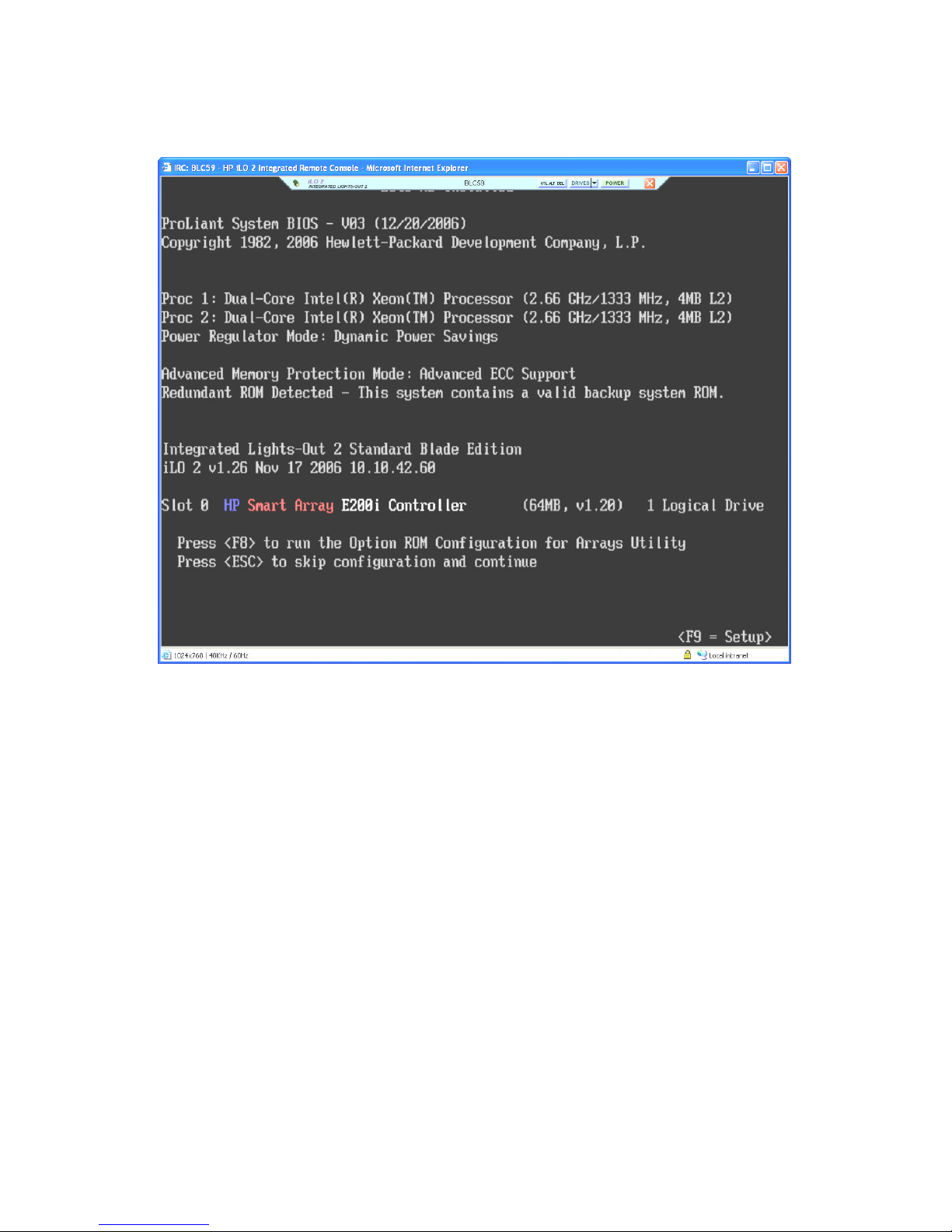
Managing the blade workstation 80
In Figure 12-6, the Integrated Remote Console is displaying the boot console. This enables you to remotely
interact with the boot process in the same manner as when a monitor, keyboard, and mouse are connected
directly to the blade.
Figure 12-6 Boot console
Page 81
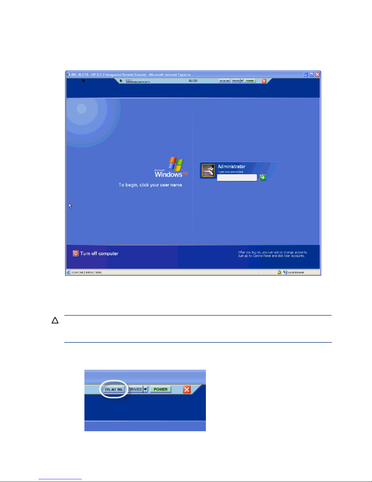
Managing the blade workstation 81
12-2-3 Viewing the Windows desktop
If Remote Console Mode is set to Admin Mode or Setup Mode, the Windows desktop is generated by the ATI
video controller and is viewable through the iLO 2 Remote Console (see Figure 12-7).
Figure 12-7 Windows desktop
During normal use, Remote Console Mode is set to User Mode, which means that the Windows desktop is
generated by the NVIDIA graphics adapter. In this case, the iLO 2 Remote Console (which is generated by the
ATI video controller) goes blank after Windows starts up.
CAUTION: If you press Ctrl+Alt+Del on the keyboard of the PC that displays the iLO 2 Windows desktop, your
PC will respond, not the blade. This is why the iLO 2 Remote Console provides the Ctrl+Alt+Del button, which
sends this keystroke combination to the blade (see Figure 12-8).
Figure 12-8 The Ctrl+Alt+Del button
Page 82
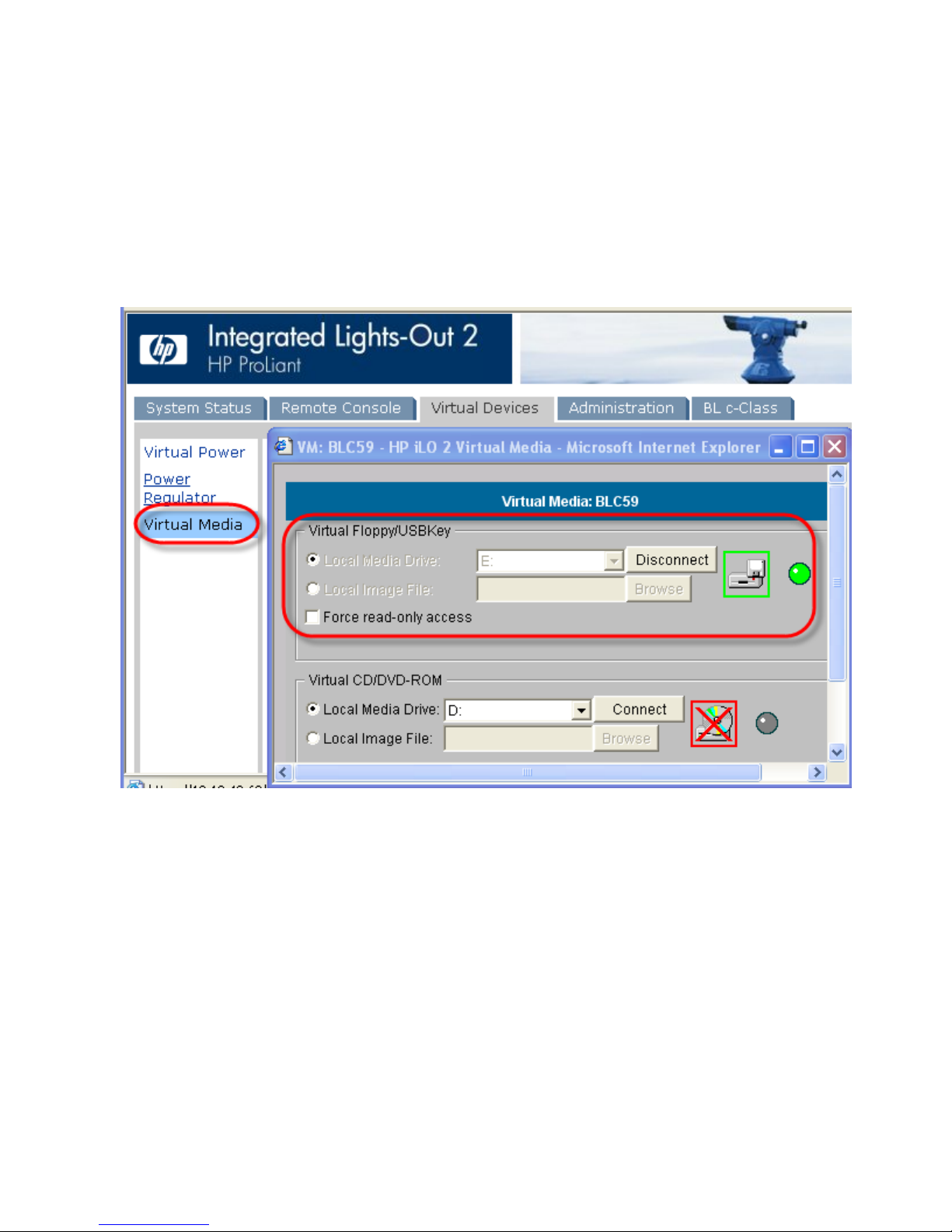
Managing the blade workstation 82
12-2-4 iLO 2 virtual media
The iLO 2 Virtual Media screen allows you to connect a floppy drive, USB key, or CD/DVD drive to the blade
workstation from your local PC. To create this connection, perform the following steps:
1. Click the iLO 2 Virtual Devices tab.
2. Click the Virtual Media link.
3. Select the media on your PC to connect to the blade workstation and click the Connect button.
In Figure 12-9, a USB key (device E:) is connected to the blade workstation.
Figure 12-9 Connecting virtual media
Page 83
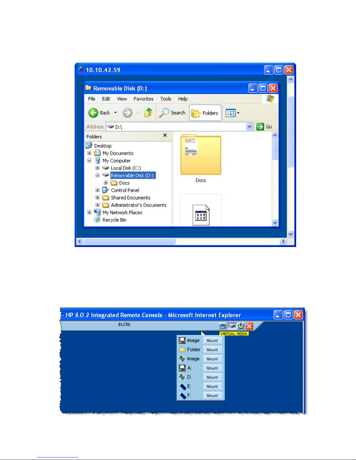
Managing the blade workstation 83
To verify that the virtual media is connected to the blade, you can use RGS to run Windows Explorer on the
blade. Figure 12-10 shows that the USB key files are now accessible from the blade workstation. Note that the E:
drive on the PC is mapped to the D: drive on the blade workstation.
Figure 12-10 PC files accessible from the blade workstation Windows desktop
Local image files on the PC can also be connected to the blade workstation by selecting Local Image File under
Virtual Floppy/USB Key or Virtual CD/DVD-ROM, and providing the file name (refer again to Figure 12-9).
The Integrated Remote Console can also be used to mount local drives, folders or images from the PC to the
blade workstation (see Figure 12-11).
Figure 12-11 Mounting of virtual media to the blade workstation using the Integrated Remote Console
Page 84
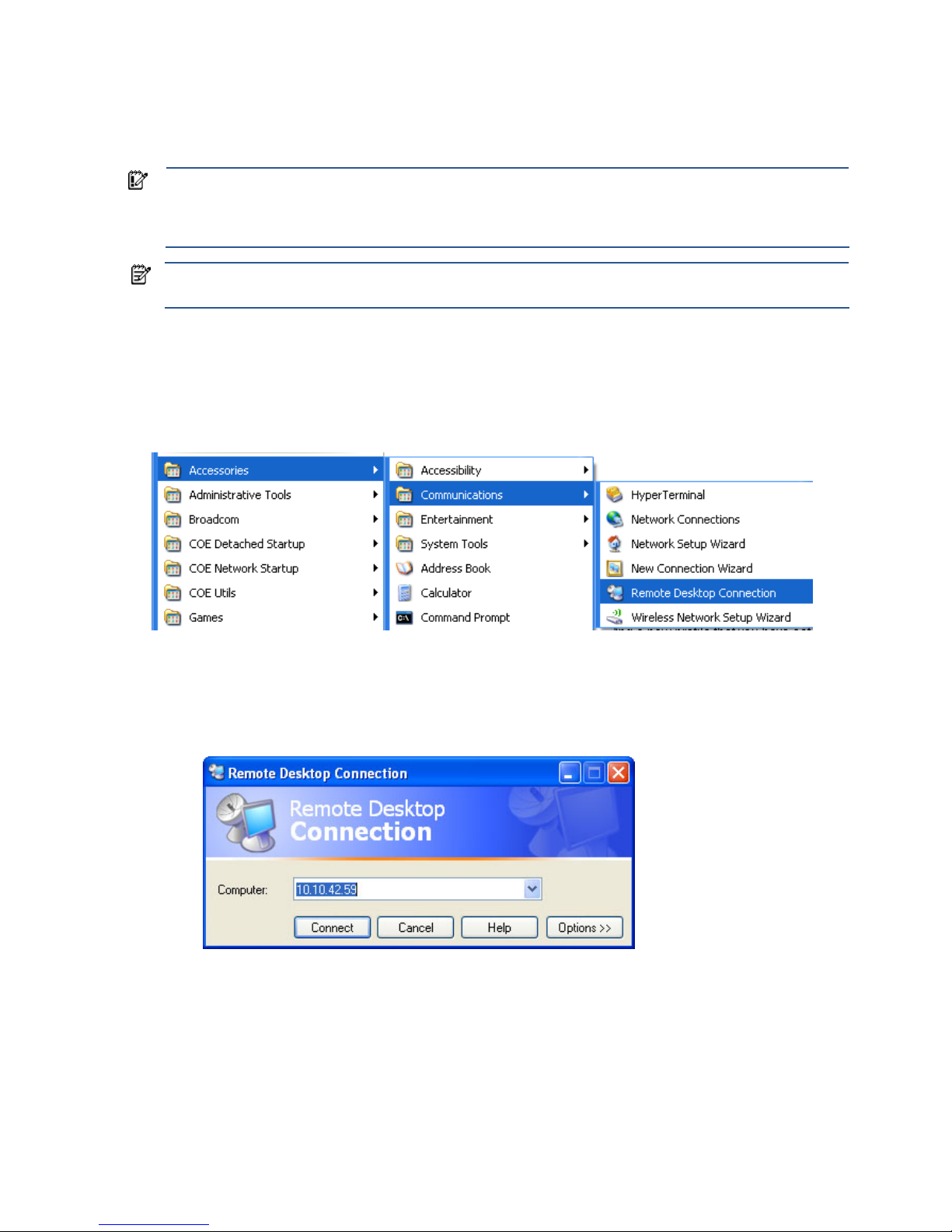
Managing the blade workstation 84
12-3 Remote Desktop Connection
Microsoft Remote Desktop Connection (RDC) provides a convenient way to remotely administer the blade
workstation because it allows the administrator to use the familiar Windows interface.
IMPORTANT: RDC and RGS are not interoperable. If an RDC connection is made while an RGS session is
established, the blade RGS Sender disconnects and the RGS session terminates. After the RDC connection
terminates, the RGS Sender resumes automatically, and users can connect to the blade with RGS. See the RGS
User Guide for more details.
NOTE: Prior to RGS 5.1.3, RDC could not be used to remotely install RGS. For RGS 5.1.3 and later, RDC can
be used to install RGS.
An RDC connection is made using the following steps:
1. Start Remote Desktop Connection by clicking Start > Accessories > Communications > Remote Desktop
Connection (see Figure 12-12).
Figure 12-12 Remote Desktop Connection menu
2. RDC displays a dialog box for entry of the blade workstation NIC1 or NIC2 IP address (see Figure 12-13).
In Figure 12-13, the NIC1 IP address is entered.
Figure 12-13 Blade IP address
Page 85
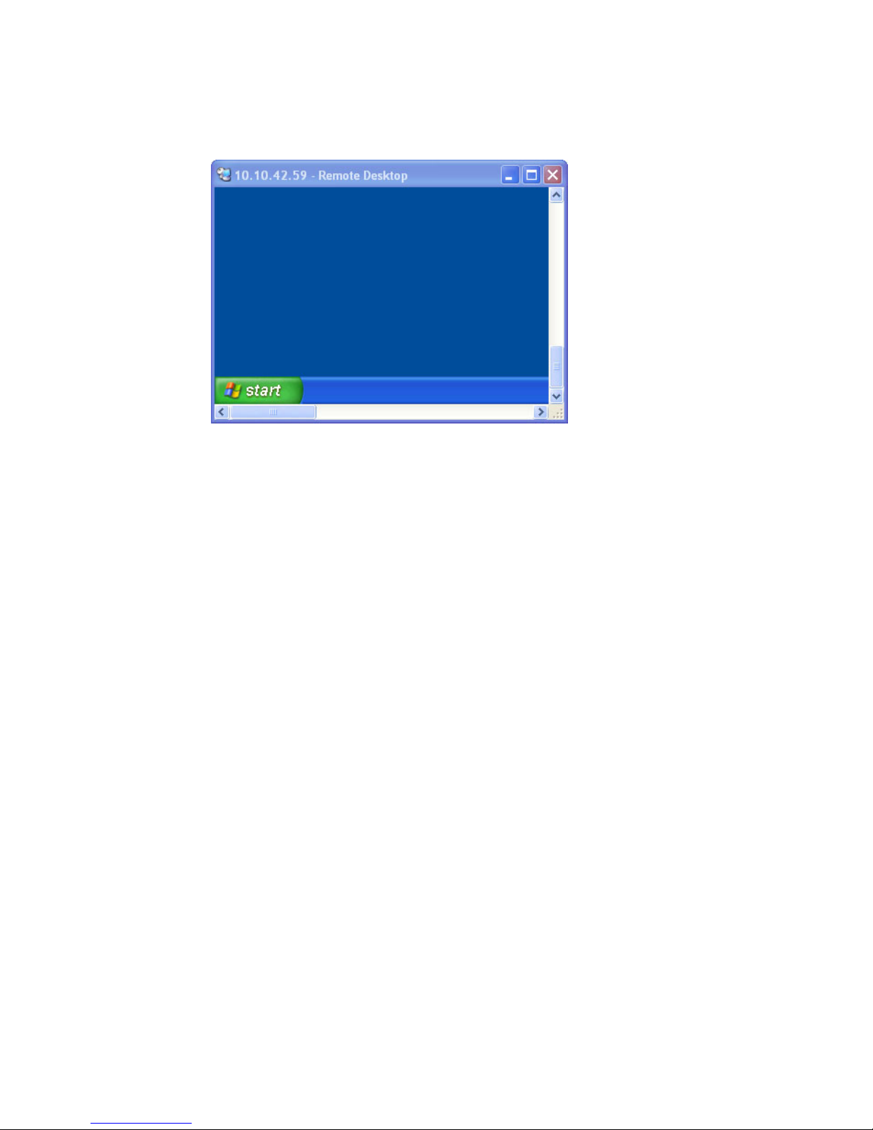
Managing the blade workstation 85
3. Click Connect. The Remote Desktop window appears with the Log On to Microsoft Windows screen. After
logging in, the Windows desktop is displayed (Figure 12-14 shows the Windows desktop, reduced in
size).
Figure 12-14 RDC Windows desktop
Page 86
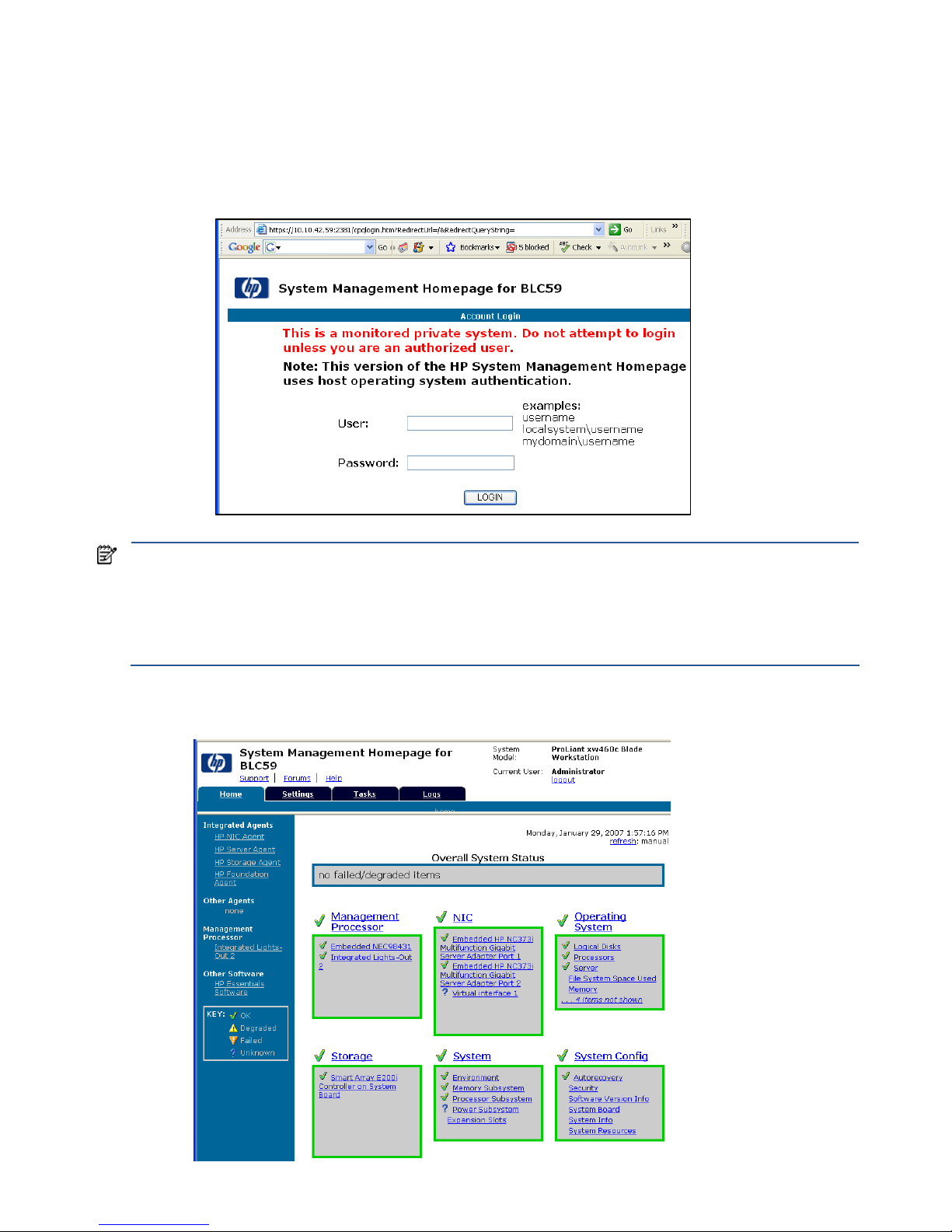
Managing the blade workstation 86
12-4 System Management Homepage
This section describes how to view the blade System Management Homepage (SMH). SMH allow you to view
information generated by the four blade management agents—NIC, server, storage, and foundation. To access
SMH, point your browser to either of the blade IP addresses (NIC1 or NIC 2) using HTTPS and port number
2381. Figure 12-15 shows the SMH login screen.
Figure 12-15 SMH login screen
NOTE: If your credentials are correct, but you’re unable to log into SMH, making the following change to the blade
security options may help:
1. Go to Control panel > Administrative Tools > Local Security Policy > Security Options
2. Ensure that “Network Access: Sharing and security model for local accounts” is set to “Classic – local
users authenticate as themselves.” Note that this setting is also required for RGS operation, and may
have already been set.
After logging in, the Overall System Status page is displayed (see Figure 12-16).
Figure 12-16 System status page
Page 87
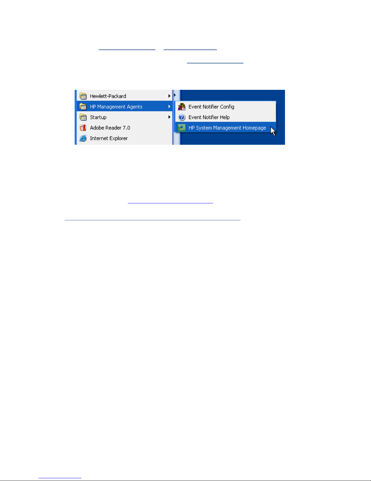
Managing the blade workstation 87
12-4-1 Local access to SMH
If you have a monitor, keyboard, and mouse connected to the Local I/O Cable, you can view SMH using either
of these URLs: https://127.0.0.1:2381 or https://localhost:2381. Or, you can access SMH from the Start menu
by clicking Start > All Programs > HP Management Agents > HP System Management Homepage (see Figure
12-17), which opens a browser window pointed to https://127.0.0.1:2381
.
Figure 12-17 Accessing SMH from the Start Menu
12-5 HP Systems Insight Manager
The blade workstation is designed to work with HP Systems Insight Manager (HP SIM). If you created a custom
Windows image, ensure that SNMP and the HP Insight Management Agents for Windows are installed as
described in Section 4-2, “Creating the Windows XP-32 image”—these are both required by HP SIM.
For more information about HP SIM (including how to download and install it), see
h18000.www1.hp.com/products/servers/management/hpsim/index.html
.
Page 88

Managing the blade workstation 88
12-6 HP Rapid Deployment Pack
12-6-1 Introduction
The HP ProLiant Essentials Rapid Deployment Pack (HP RDP) is a software deployment solution that facilitates the
installation, configuration, and deployment of high volumes of blade workstations through either a GUI-based or
web-based console. HP RDP is designed to automate repetitive tasks such as configuring and deploying
operating system images, configuring network switches, and configuring BIOS settings. System configuration time
is reduced, making it possible to rapidly scale blade workstation deployments to high volumes.
This section focuses primarily on image capture and image deployment techniques using HP RDP for the blade
workstation. It is assumed you have basic knowledge of HP RDP and Windows image creation and installation.
For more information about HP RDP, see the HP website at
h18004.www1.hp.com/products/servers/management/rdp.html
.
12-6-2 HP RDP content
HP RDP is based on Altiris Deployment Solution (DS) technology. Functionality specific to HP ProLiant Systems is
added by the ProLiant Integration Module (PIM)—a collection of scripts that have been predefined for ProLiant
systems to perform routine tasks. Interaction with Altiris DS occurs in a GUI or web-based environment called the
Deployment Server Console. The DS Console provides a drag-and-drop interface for assigning jobs to computers
(drag computer to job or job to computer). Toolbar buttons provide shortcuts to common Altiris DS tasks.
12-6-3 Infrastructure requirements
HP RDP requires the following:
• DHCP server
• PXE server
• Altiris Deployment Solution
• A database—either Microsoft SQL Server or Microsoft Data Engine (MSDE). Refer to the HP ProLiant
Essentials Rapid Deployment Pack—Window Edition Installation Guide 2.00
at
h200005.www2.hp.com/bc/docs/support/SupportManual/c00294271/c00294271.pdf for more
information.
12-6-4 HP RDP-specific differences between server blades and blade
workstations
There are several differences between server blades and blade workstations that affect HP RDP:
• The operating systems are different.
• The blade workstation operating system is preinstalled on the hard drive.
• The blade workstation boots differently from the server blade.
• The server blade supports several software tools not supported by the blade workstation.
These differences combine to limit some HP RDP functionality for the blade workstation, as described in the
following sections.
12-6-4-1 Operating system
Windows XP-32 the blade workstation differs from Windows Server on the server blade in several ways that
affect how an administrator uses HP RDP:
• HP RDP versions prior to version 3.82 do not support scripted installs on Windows XP—To deploy
Windows XP-32 the blade workstation using HP RDP prior to version 3.82, the administrator must create a
reference image, outside of HP RDP, and then deploy that image to target systems using the Image Capture
and Image Deployment features of HP RDP. HP RDP 3.82 and higher support scripted installs on Windows
XP-32.
Page 89

Managing the blade workstation 89
• Windows XP uses Microsoft Windows Activation technologies—Microsoft Windows Activation requires
either that users activate their Windows license on each machine at first boot or that the administrator take
specific steps during image creation to ensure that activation is not needed. Microsoft Windows Activation
is not required on the server blade.
12-6-4-2 Preinstalled operating system
The blade workstation is shipped with Windows XP-32 pre-installed on the hard drive. Server blades have no
operating system preinstalled. When a new blade workstation is booted the first time, it boots to the pre-installed
Windows XP-32, not PXE, unless steps are taken to change this behavior.
HP RDP automatically identifies deployed computers but only if they boot to PXE or have the Altiris Aclient
installed in the Windows image, and are correctly configured for the specific HP RDP server. The preinstalled
blade workstation operating system does not include the Aclient because it must be specifically configured for
each site. Therefore, new blade workstations are not automatically detected by HP RDP.
For more information, see Section 12-6-5, “Use Rip-n-Replace and Virtual Bay features to replace failed systems
.”
12-6-4-3 Booting
The blade workstation boot process differs from the server blade boot process in two ways:
• The blade workstation boots from the hard drive—Booting from the hard drive occurs because there is an
OS installed on the hard drive. With the server blade, PXE booting occurs because there is no OS installed.
If PXE booting is required on the blade workstation, the administrator will need to use the iLO 2 remote
console to force PXE booting to occur.
• The blade workstation is shipped with Remote Console Mode set to User Mode—This is desirable for most
systems because RGS, using the NVIDIA graphics adapter, offers better performance than the ATI video
controller. However, because the RGS is not preinstalled on the operating system image, the administrator
might need to set Remote Console Mode to Admin Mode to create the reference image.
12-6-4-4 Software tools
Several software tools have limited support for the blade workstation:
• ProLiant Support Packs are not currently supported on the blade workstation.
• The SmartStart Scripting Toolkit is not supported on the blade workstation. In particular, the Conrep.exe tool
and server deployment jobs that capture firmware settings (for example, the default Hardware
Configuration or Server Deployment jobs) do not capture settings for features that are unique to the blade
workstation, such as Remote Console Mode. These settings must be configured using iLO 2 or the local I/O
cable.
12-6-5 Use Rip-n-Replace and Virtual Bay features to replace failed systems
Both the Rip-n-Replace and the Virtual Bay functionality of the blade systems architectures should also function on
blade workstations. However, a new system placed into the Virtual Bay is not detected until it is either PXE
booted or booted with an image that has the Aclient installed and configured. Automatic deployment jobs are
then enabled. The default for the blade workstation is to boot to the Windows XP Professional image preinstalled
on the hard drive, which does not have the Aclient installed or configured.
Page 90

Managing the blade workstation 90
12-7 HP Insight Diagnostics
The HP Insight Diagnostics utility enables you to perform and view critical computer hardware and software
configuration information from various sources. This utility enables you to run diagnostics and view the hardware
configuration of the system.
NOTE: As noted below, the HP Insight Diagnostics are available on the Documentation and Diagnostics CD
that is included with your blade workstation. The server version of these diagnostics, available on the
SmartStart CD, is not supported on the blade workstation.
12-7-1 Key features and benefits
HP Insight Diagnostics simplifies the process of identifying, diagnosing, and isolating hardware issues. In
addition to robust management tools, service tools can be invaluable for quickly resolving system problems. To
streamline the service process and resolve problems quickly, it is necessary to have the right information
available at the time a service call is placed. The primary information requirement, which is also the one that
provides the greatest insight into potential system issues, is the system configuration.
Typical uses of Insight Diagnostics are:
• Testing and diagnosing apparent hardware failures
• Documenting system configurations for upgrade planning, standardization, inventory tracking, disaster
recovery, and maintenance
• Sending configuration information to another location for in-depth analysis
12-7-2 Theory of operation
HP Insight Diagnostics Offline Edition operates in offline mode only—the operating system is not running, and
information from the operating system is not available to the diagnostics. Offline Survey is available to display
the current system configuration.
The Insight Diagnostics Test feature enables you to test functionality of all the major hardware components in the
system. This feature is flexible to enable you to customize test selections by providing different modes and types
of testing. It includes Quick, Complete, and Custom testing levels to give you control over testing depth and
required user interaction.
12-7-3 Accessing HP Insight Diagnostics
HP Insight Diagnostics is available on the Documentation & Diagnostic CD included with your blade workstation.
To start the diagnostic utility on the CD:
1. Power on your workstation and press the F10 key during the initial boot process to enter the Computer
Setup utility.
2. Select your language from the list and press the Enter key. In the Computer Setup Utilities menu, four
headings are displayed: File, Storage, Security and Advanced. Other headings might be displayed,
depending on the workstation.
3. Use the right arrow key to select Storage.
4. Use the down arrow key to select Boot Order and press Enter.
5. Select CD/DVD drive and enable it as a bootable device by pressing the F5 key. If not already enabled,
pressing the F5 key again disables the device. The default setting is enabled.
6. Set the CD/DVD drive to the top of the boot order. Select CD/DVD, press the Enter key and use the up
arrow to move it to the top of the boot order.
7. To apply and save changes, press the F10 key and select File>Save Changes and Exit.
8. Insert the Documentation & Diagnostic CD into the workstation.
9. Restart the blade. HP Insight Diagnostics launches automatically.
Page 91

Managing the blade workstation 91
12-7-4 Survey tab
The Survey tab displays important system configuration information. In the View section on the left side of the
screen, you can select the Summary view to see limited configuration data or select the Advanced view to see all
the data in the selected category. The following categories of information are available on the Survey tab:
• All—Provides a listing of all categories of information about the computer.
• Overview—Provides a listing of general information about the computer.
• Architecture—Shows they type of bus the computer uses and BIOS information. In addition, if the bus is a
PCI, information about the PCI configuration is displayed.
• Asset Control—Shows asset tag, system serial number, and processor information.
• Communication—Shows information about the computer parallel port (LPT) and serial port (COM) settings,
and USB and network controller information.
• Graphics—Shows information about the graphics controller of the computer.
• Input Devices—Shows information about the keyboard, mouse, and other input devices connected to the
computer.
• Memory—Shows information about all memory in the computer. This includes memory slots on the system
board and any memory modules installed.
• Miscellaneous—Shows information obtained from the computer configuration memory (CMOS), system
management BIOS data, system board data, and diagnostics component information.
• Storage—Shows information about storage media connected to the computer. This list includes all fixed
disks, diskette drives, and optical drives.
• System—Shows information about the system board, processor, chassis, and BIOS, plus internal speaker
and PCI bus information.
12-7-5 Test tab
The Test tab enables you to choose various parts of the system to test. You can also choose the type of test and
testing mode. There are three types of tests to choose from:
• Quick Test—Provides a predetermined script for which a sample of each hardware component is tested.
Quick Test requires no user intervention in either Unattended or Interactive mode.
• Complete Test—Provides a predetermined script in which each hardware component is fully tested. You can
select Interactive or Unattended tests, which will change the devices tested during the Complete Test. Most
tests are available in Interactive mode but require user intervention.
• Custom Test—Provides the most flexibility in controlling testing. Custom Test mode enables you to
specifically select which devices, tests, and test parameters are run. You can select tests that do not require
any user interaction using the Interactive or Unattended test modes. More tests are available in Interactive
mode but require user intervention.
To begin testing:
1. Click the Test tab.
2. Select Type of Test to perform and select Interactive or Unattended as the test mode.
3. Determine how you want the test to be executed.
a. Select Number of Loops and enter the number of loops to perform.
b. Select Total Test Times and enter the amount of time in minutes that you want the diagnostic test to run.
4. When choosing to run the test over a specified number of loops, enter the number of loops to perform. If
you want to run the diagnostic test for a specified time period, enter the amount of time in minutes.
5. Click Begin Testing in the lower right corner of the display to start the test.
While tests are being performed, you can monitor the progress by clicking the Status tab. Any errors that are
detected are summarized in the Error Log. Click Save to save the report to a diskette or a USB key drive (if
attached).
If the diagnostics utility detects an error during a test, you can mouse-over the failed text in the Status tab to
display additional information about the type of error and the error code.
To view all test failure information, select Error Log. To view the status of all testing that has been performed click
the Log tab.
Page 92

Managing the blade workstation 92
12-7-6 Status tab
The Status tab displays the status of selected tests. The type of test executed (Quick, Complete, or Custom) is also
displayed. The main progress bar displays the percent complete of the current set of tests. While testing is in
progress, a Cancel Testing button is available if you want to cancel the test.
After testing is complete, the Cancel Testing button is replaced with two buttons, Select New Tests and Retest. To
go back to the previous test selection page to select a new set of tests, click the Select New Tests button. To run
the last set of tests executed without having to go back to the test selection page, click the Retest button.
The Status tab also shows:
• Devices being tested
• Tests that are running
• Overall elapsed time
• Individual elapsed test times
• Condition status of each test
12-7-7 Log tab
The Log tab displays two types of logs:
• Test Log—Displays all tests that have been executed, number of times the tests were executed, number of
times the tests failed, and the time it took to complete the tests. To clear the contents of the Test Log, click the
Clear Test Log button.
• Error Log—Displays the tests that have failed during diagnostic testing. In addition to displaying the
devices and tests, this section can also include error details. The description section describes the errors
found by the diagnostic tests. To view a recommended action to resolve an error, click the Recommended
Repair button. The error count is the number of times the test has failed. To clear contents of the Error Log,
click the Clear Error Log button.
12-7-8 Help tab
The Help tab has three views:
• HP Insight Diagnostics—Provides introductory and detailed information about Insight Filed Diagnostics.
• Error Codes—Provides error code listings, including device tested, messages, and recommended repair
information.
• Test Components—Reloads and refreshes all components and displays component details after the refresh.
The Help tab provides the following options:
• Reload—Located in the upper-right corner of the display, this selection reloads all hardware components.
• About—Provides Insight Diagnostics revision details.
• Exit—Located in the lower-left corner of the screen, this selection provides the option to exit diagnostics.
12-7-9 Saving and printing information in HP Insight Diagnostics
You can save information displayed in the HP Insight Diagnostics Status and Log tabs to a diskette or USB 2.0
drive key (64MB or higher). You cannot save this information to the hard drive. The system automatically creates
an html file that looks the same as the information displayed on the screen.
1. Insert a diskette or USB 2.0 drive key (capacity must be 64MB or higher). USB 1.0 drive keys are not
supported.
2. Click Save in the upper right corner of the tab.
3. Select Save to the floppy or Save to USB key.
4. Enter a file name in the File Name box and click the Save button. An html file is saved on the diskette or
USB drive key.
5. Print the information from the diskette or USB drive key.
NOTE: To exit HP Insight Diagnostics, click Exit in the upper-right corner of the screen and remove the
Documentation and Diagnostics CD from the optical drive.
Page 93

Managing the blade workstation 93
12-7-10 Downloading the latest version of HP Insight Diagnostics
1. Go to www.hp.com.
2. Click the Support & Drivers link.
3. Select the Download driver and software radio button.
4. Enter your product number (for example, “xw460c”) in the text box, and press the Enter key.
5. Select your operating system.
6. Click the Diagnostic link.
7. Locate HP Insight Diagnostics, and click Download.
NOTE: The download includes instructions for creating a bootable CD.
12-8 ROM-Based Setup Utility
The ROM-Based Setup Utility (RBSU) allows BIOS parameters to be changed during the boot process. For
example, Remote Console Mode is set using RBSU—see Section 2-1, “Setting Remote Console Mode“. For details
on RBSU options, see the HP ROM-Based Setup Utility User Guide on the HP website
www.hp.com/support/xw460c_manuals.
12-9 Power-on Self Test
At power-on, the blade workstation performs Power-On Self Test (POST). See the “Troubleshooting” chapter of the
HP ProLiant BL460c Server Blade User Guide (available at www.hp.com/support/xw460c_manuals)
for
information about the POST process, including the POST troubleshooting flowchart.
12-10 BIOS Serial Console
BIOS Serial Console allows you to configure the serial port on the local I/O cable to view POST error messages
and run RBSU—a keyboard and mouse are not required. For more about BIOS Serial Console, see the BIOS
Serial Console User Guide on the HP website at www.hp.com/support/xw460c_manuals.
12-11 BIOS programming
HP provides a downloadable SoftPaq to update the BIOS. To see if there is a more recent BIOS than the version
on your blade workstation, follow the steps outlined in “APPENDIX A: Downloading and installing SoftPaqs and
Smart Components” to view the BIOS SoftPaqs. Each BIOS SoftPaq includes a version number and date. If there
is a more recent BIOS version available than the BIOS on your blade workstation, HP recommends that you
update to the latest BIOS.
NOTE: The BIOS version is not dependent on the operating system that you’re using. A common BIOS can
support all three operating systems—Windows XP-32, Windows XP-64, and RHEL 4.
Page 94

Troubleshooting the blade workstation solution 94
13 Troubleshooting the blade workstation solution
This chapter describes several possible problems you might encounter during installation and operation of the
blade workstation solution. Included with each problem is the likely cause, and the suggested solution. For
additional troubleshooting information, see:
• Section 12-9, “Power-on Self Test
”
• The following documents available at www.hp.com/support/xw460c_manuals
or
www.hp.com/support/xw2x220c_manuals
.
• HP BladeSystem c7000 Enclosure Setup and Installation Guide
• HP BladeSystem c3000 Enclosure Setup and Installation Guide
• HP BladeSystem c3000 Tower Enclosure Setup and Installation Guide
• HP ProLiant BL460c Server Blade User Guide
• HP ProLiant BL2x220c Server Blade User Guide
• HP Remote Graphics User’s Guide
• HP ProLiant Servers Troubleshooting Guide
• Documentation for your specific client computer
13-1 Troubleshooting SMH problems
Table 13-1 Troubleshooting System Management Homepage problems
Problem Cause Suggestions
Unable to access SMH locally
Cannot access SMH locally using
the local I/O cable.
Either SNMP or the HP Insight
Management Agents are not
installed. These are in the
preinstalled image but need to be
included during creation of a
custom Windows image.
Refer to Section 4-2-3, “Creating
the Windows image”, for a
description of installing SNMP and
the HP Insight Management Agents.
Unable to access SMH remotely
Can access SMH locally but cannot
access it over the network.
DHCP problem causing incorrect
NIC1 or NIC2 IP address.
Verify NIC1 and NIC2 addresses
are correct as described in Section
3-4-1, “NIC1 and NIC2
verification”.
13-2 Troubleshooting HP SIM problems
Table 13-2 Troubleshooting HP Systems Insight Manager problems
Problem Cause Suggestions
Unable to access HP SIM information
Unable to access blade workstation
information using HP SIM.
Either SNMP or the HP Insight
Management Agents are not
installed. These are in the
preinstalled image but need to be
installed during creation of a
custom Windows image.
Refer to Section 4-2-3, “Creating
the Windows image”, for a
description of installing SNMP and
the HP Insight Management Agents.
Page 95

Troubleshooting the blade workstation solution 95
13-3 Troubleshooting RGS problems
Also see the Chapter “Troubleshooting” in the HP Remote Graphics User’s Guide for additional information on
possible RGS problems and suggested solutions.
Table 13-3 Troubleshooting RGS problems
Problem Cause Suggestions
Unable to connect using RGS Receiver
A connection cannot be established
using the Remote Graphics
Receiver if the host name is used
instead of the IP address.
The proper DNS suffixes for your
network have not been entered.
1 On the client, ensure that the
correct DNS suffixes for your
blade workstation network
have been entered.
2 Use the IP address instead of
the hostname to connect to the
blade.
RGS performance problem
Client performance might appear to
be impacted when using a photo or
patterned bitmap for your blade
workstation desktop background.
A background with a large
gradient of patterns or colors
causes the RGS application to use
additional bandwidth which
reduces the bandwidth available
for other network traffic.
Use a plain colored bitmap for your
system desktop background.
RGS connection failure
If multiple user accounts exist in
Windows on the blade workstation,
the Remote Graphics connection
can fail if the RGS application login
does not match the user names
between the active Windows
session and the RGS.
To connect to the workstation from
the client, the user starts the RGS
application. The authentication
prompt prompts the user to input a
valid network domain and user
name. This user name must match
the Windows user account name
when logging onto the workstation.
If you input a different Windows
user account name, an
“Authorization failed!” error results.
Another example, after a successful
RGS connection to the workstation
is made as Windows user X, this
connection only remains viable as
long as the user X account remains
active. If the user logs out of the
Windows user X session, and then
logs back into Windows as user Y,
a “Connection Lost!” error appears.
Ensure that the user name used at
the RGS authentication prompt
matches the Windows user account
and when logging out of the one
Windows user session to log into
another.
Page 96

Troubleshooting the blade workstation solution 96
13-4 Troubleshooting Windows problems
Table 13-4 Troubleshooting Windows problems
Problem Cause Suggestions
RAM discrepancies
Blade workstation configurations
using 4 GB of RAM report only
3,456 MB during the system BIOS
POST (when the system first boots).
When using 2 GB of RAM, the
blade reports 2048 MB.
A portion of the total RAM will be
utilized by various system devices,
most notably the graphics card.
Accounting for this fact, the BIOS
does not report the total RAM
installed during the POST.
None
Unable to wake from hibernation or standby
The blade workstation will not
wake after it has gone into
Windows hibernation or standby
mode.
If the Windows option of
hibernation is enabled (with the
Power Options Properties in the
Windows Control Panel) and the
blade workstation is allowed to
hibernate, you will not be able to
wake the blade workstation from
the remote client system because
the RGS application has been
terminated by the workstation and
the client has no remote access to
turn the workstation back on.
Ensure that hibernation and
standby are disabled.
DLL initialization error
While using the Windows Restore
CD (that shipped with your blade
workstation) to restore the blade
workstation to the factory shipped
Windows operating system,
multiple “DLL Initialization Failed”
errors can appear after the first
boot into Windows.
After the initial boot into Windows,
a reboot is necessary for certain
operating system settings to take
effect. Such DLL errors are a
byproduct of this required system
reboot.
Reboot the blade. Such DLL errors
should not occur on any subsequent
reboots into Windows.
Print warning in event logs
“Print” warnings can appear in the
blade workstation Windows System
Event Log when using the Windows
Remote Desktop Connection
application to access the
workstation.
Networked client printers are
automatically installed to the blade
workstation when a Windows
Remote Desktop Connection
between a Windows client PC to a
blade workstation has been made.
As the connection to the
workstation is terminated, such
“Print” warnings can appear as
these printers are deleted.
Accessing the blade using RGS
does not generate such warnings.
(These warnings do not affect the
functionality of the blade or client.)
Page 97

APPENDIX A: Downloading and installing SoftPaqs and Smart Components 97
APPENDIX A: Downloading and installing SoftPaqs and
Smart Components
This appendix describes how to find, download, and unpack SoftPaqs and Smart Components for the blade
workstations.
IMPORTANT: HP supports two types of software packages for downloadable software and drivers:
1. SoftPaqs
2. Smart Components
Until recently, blade workstation downloads were based on SoftPaqs. Starting in the fall of 2007, a transition
began to using Smart Components for new blade workstation downloads. Because Smart Components are
already used by HP ProLiant servers, using Smart Components for blade workstations provides a common
packaging (and deployment) methodology across both server blades and blade workstations.
While new downloads will be released as Smart Components, there are still a number of SoftPaqs on the
blade workstation download web page. Over time, as new downloads are released, these SoftPaqs will be
replaced by Smart Components.
A-1 Downloading and installing SoftPaqs
Perform the following steps to download, unpack, and install SoftPaqs.
1. Depending on your blade workstation, go to the appropriate website:
xw460c blade workstation: www.hp.com/support/xw460c
xw2x220c blade workstation: www.hp.com/support/xw2x220c
2. Select Download drivers and software.
Page 98
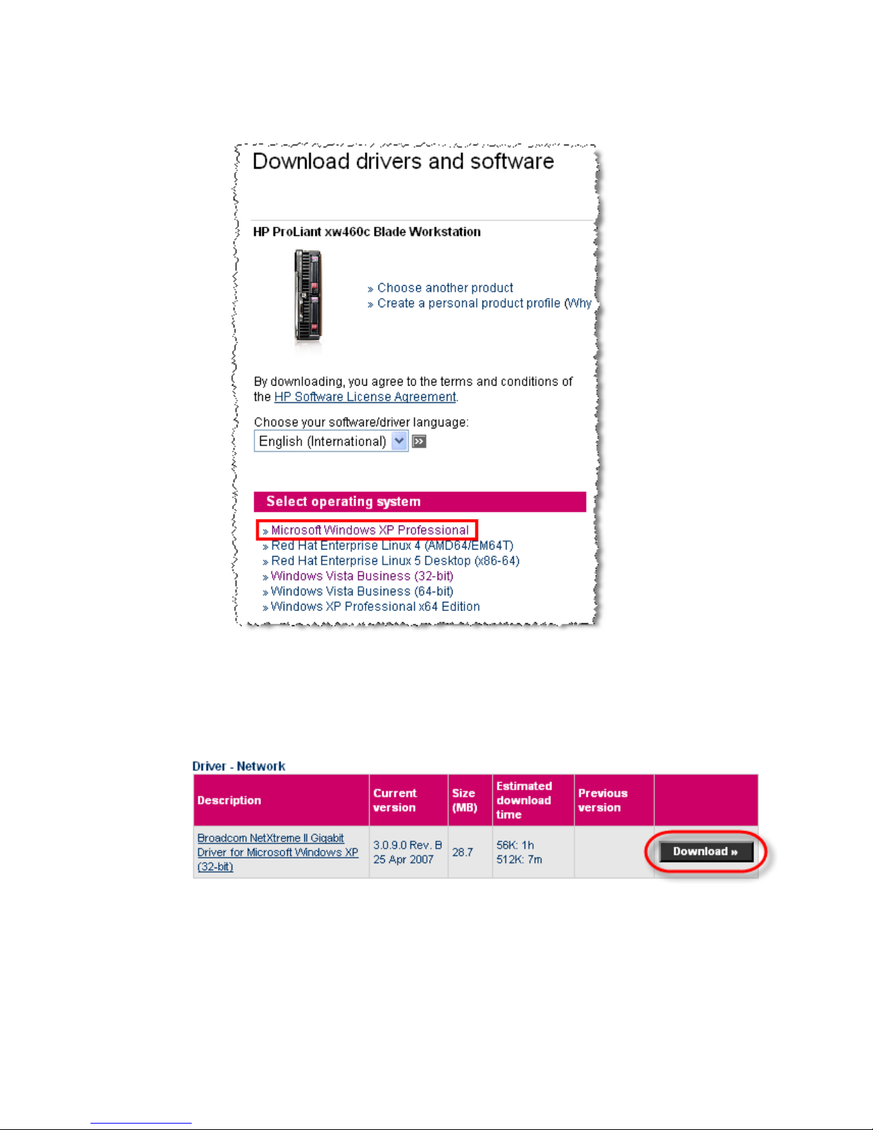
APPENDIX A: Downloading and installing SoftPaqs and Smart Components 98
3. Select your operating system (see Figure A-1). For this example, Microsoft Windows XP Professional is
selected.
Figure A-1 Operating system selection options
4. On the next page, scroll down to the driver of interest, and click the Download button. The Broadcom
network driver is used in this example. To download the Broadcom driver, click the Download button as
shown in Figure A-2.
Figure A-2 Broadcom network driver SoftPaq
Page 99
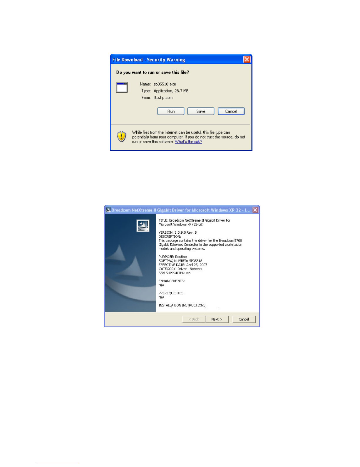
APPENDIX A: Downloading and installing SoftPaqs and Smart Components 99
5. In the file download window shown in Figure A-3, select Save, and save the SoftPaq file sp35518.exe to a
temporary location on the blade workstation.
Figure A-3 SoftPaq file download window
6. When the download window indicates the download is complete, click Run. This brings up the SoftPaq
start window shown in Figure A-4. Click Next to review the License Agreement, and click Next if the terms
are acceptable.
Figure A-4 Softpaq startup window
Page 100
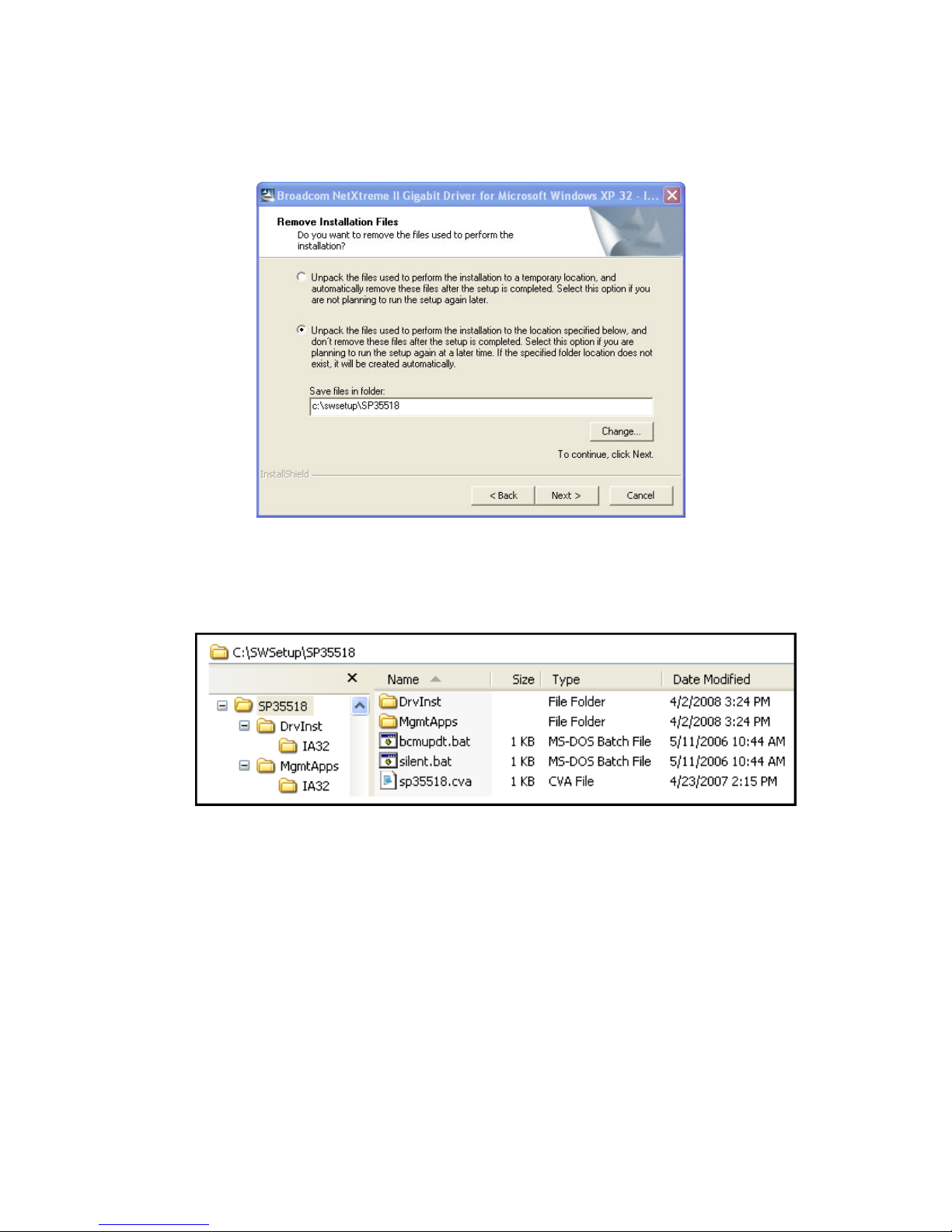
APPENDIX A: Downloading and installing SoftPaqs and Smart Components 100
7. For this particular SoftPaq, you are given the option of unpacking the SoftPaq files to a temporary location
(followed by their post-installation removal) or to a user-settable location (which leaves the files intact). In
Figure A-5, the user-settable location option is selected, and the default location C:\swsetup\SP35518 is
used.
Figure A-5 Specifying the unpacking location of the SoftPaq files
Figure A-6 shows the unpacked Broadcom SoftPaq files.
Figure A-6 Unpacked SoftPaq files
8. Continue to follow the instructions to complete installation of the Broadcom SoftPaq.
 Loading...