

HP ProLiant xw2x220c, ProLiant xw460c Blade Workstation Administrator's Manual

Administrator’s Guide for Microsoft Windows
on HP ProLiant Blade Workstations
January 2009
Part number: 443069-004
Fourth edition: January 2009

2
© Copyright 2009 Hewlett-Packard Development Company, L.P.
The information contained herein is subject to change without notice. The only warranties for HP products and services are set forth in the
express warranty statements accompanying such products and services. Nothing herein should be construed as constituting an additional
warranty. HP shall not be liable for technical or editorial errors or omissions contained herein.
Windows and Windows Server are registered trademarks of Microsoft Corporation in the United States and other countries.
Intel and Xeon are trademarks of Intel Corporation in the United States and other countries.
Part number: 443069-004
Fourth edition: January 2009
Audience Assumptions
This guide is for the person who installs, administers, and troubleshoots blade workstations and client access
devices. HP assumes you are qualified in the servicing of computer equipment and trained in recognizing
hazards in products with hazardous energy levels and are familiar with weight and stability precautions for rack
installations.

Contents 3
Contents
1 Introduction
1-1 Nomenclature...................................................................................................................... 8
1-2 Administrator’s Guide organization ...................................................................................... 10
1-3 Blade workstation solution documents ................................................................................... 11
1-4 Obtaining HP technical support ........................................................................................... 12
1-5 Customer Self Repair .......................................................................................................... 12
1-6 Ordering Windows recovery media ..................................................................................... 12
1-7 Microsoft Windows licensing............................................................................................... 12
2 Blade workstation video subsystem
2-1 Setting Remote Console Mode ............................................................................................. 16
2-2 Admin Mode ..................................................................................................................... 17
2-3 Setup Mode ......................................................................................................................18
2-4 User Mode........................................................................................................................ 19
2-5 Summary of Remote Console Modes..................................................................................... 20
3 Installing, powering on, booting, and validating the blade workstation solution
3-1 Setting up the client computer .............................................................................................. 22
3-2 Installing and turning on the blade workstation ...................................................................... 22
3-2-1 Preparing the blade workstation infrastructure........................................................................ 22
3-2-2 Configuring the blade workstation hardware ......................................................................... 23
3-2-3 Connecting media to the blade workstation ........................................................................... 24
3-2-4 Powering on the blade workstation....................................................................................... 25
3-2-5 Blade workstation sleep states.............................................................................................. 26
3-3 The OOBE screens ............................................................................................................. 26
3-4 Verifying networking .......................................................................................................... 27
3-4-1 NIC1 and NIC2 verification ................................................................................................ 27
3-4-2 iLO 2 network verification ................................................................................................... 28
3-5 Installing, configuring, and verifying RGS.............................................................................. 29
3-5-1 Installing RGS.................................................................................................................... 29
3-5-2 Setting the RGS NIC binding order....................................................................................... 29
3-5-3 Setting User Mode ............................................................................................................. 31
3-5-4 Verifying RGS operation ..................................................................................................... 31
3-6 Installing applications .........................................................................................................31
3-7 Validating the solution ........................................................................................................ 32
3-8 Integrate additional blade workstations and client computers................................................... 32
3-9 Optional: Configure network teaming ................................................................................... 32
4 Creating a custom Windows XP-32 image
4-1 Components in the factory-installed Windows XP-32 image ..................................................... 34
4-2 Creating a custom Windows XP-32 image............................................................................. 35
4-2-1 Required components ......................................................................................................... 35
4-2-2 Optional software components............................................................................................. 36
4-2-3 Creating the Windows XP-32 image..................................................................................... 36
4-2-4 Configuring the operating system ......................................................................................... 45
4-2-5 Verifying the network connections ........................................................................................ 47
4-2-6 Installing and verifying RGS ................................................................................................ 47
4-2-7 Installing the applications .................................................................................................... 47
4-2-8 Validating the solution ........................................................................................................ 47
4-2-9 Deploying the Windows image............................................................................................ 47
5 Restoring Windows XP-32
5-1-1 Hardware configuration...................................................................................................... 48
5-1-2 Restoring Windows XP-32 from the RestorePlus! CD................................................................ 48
6 Using Windows XP-64 on the blade workstation

Contents 4
6-1 Windows XP-64 processes .................................................................................................. 49
7 Using Windows Vista on the blade workstation
7-1 Acquiring Windows Vista ................................................................................................... 50
7-2 Installing Windows Vista..................................................................................................... 50
7-2-1 Hardware configuration...................................................................................................... 50
7-2-2 Windows Vista installation steps .......................................................................................... 51
7-3 Viewing the Windows Vista desktop..................................................................................... 51
8 Capturing a blade workstation image using HP RDP
9 Deploying a blade workstation image using HP RDP
10 Performing an unattended installation of Windows XP-32 and Windows XP-64
10-1 Assumptions ...................................................................................................................... 58
10-2 Unattended installation procedure ........................................................................................ 59
11 User Information
11-1 Introduction ....................................................................................................................... 68
11-2 Powering on the HP blade workstation client.......................................................................... 68
11-3 Changing the behavior of RGS ............................................................................................ 68
11-4 Connecting from the client to the blade ................................................................................. 69
11-4-1 Using Enterprise Directory ......................................................................................... 69
11-4-2 Using a local directory file......................................................................................... 70
11-4-3 Using manual entry................................................................................................... 70
11-5 Sending Ctrl+Alt+Delete to the blade workstation................................................................... 71
11-6 Accessing blade workstation desktop windows ...................................................................... 71
11-7 Moving desktop windows between monitors.......................................................................... 72
11-8 Spanning multiple displays with a desktop window ................................................................ 72
11-9 Maximizing a window to a single display ............................................................................. 72
11-10 Supported USB devices....................................................................................................... 73
11-11 Synchronizing a PDA.......................................................................................................... 73
11-12 Adjusting audio volume on the client and blade ..................................................................... 73
11-13 Disconnecting the client from the blade workstations............................................................... 74
11-14 Reconnecting to disconnected sessions.................................................................................. 74
12 Managing the blade workstation
12-1 Onboard Administrator....................................................................................................... 76
12-2 Integrated Lights-Out 2 (iLO 2) ............................................................................................. 78
12-2-1 Accessing iLO 2....................................................................................................... 78
12-2-2 iLO 2 Remote Console .............................................................................................. 79
12-2-3 Viewing the Windows desktop................................................................................... 81
12-2-4 iLO 2 virtual media................................................................................................... 82
12-3 Remote Desktop Connection ................................................................................................ 84
12-4 System Management Homepage.......................................................................................... 86
12-4-1 Local access to SMH................................................................................................. 87
12-5 HP Systems Insight Manager................................................................................................ 87
12-6 HP Rapid Deployment Pack ................................................................................................. 88
12-6-1 Introduction ............................................................................................................. 88
12-6-2 HP RDP content ........................................................................................................ 88
12-6-3 Infrastructure requirements ......................................................................................... 88
12-6-4 HP RDP-specific differences between server blades and blade workstations...................... 88
12-6-5 Use Rip-n-Replace and Virtual Bay features to replace failed systems ............................... 89
12-7 HP Insight Diagnostics ........................................................................................................ 90
12-7-1 Key features and benefits .......................................................................................... 90
12-7-2 Theory of operation .................................................................................................. 90
12-7-3 Accessing HP Insight Diagnostics................................................................................ 90
12-7-4 Survey tab............................................................................................................... 91
12-7-5 Test tab................................................................................................................... 91
12-7-6 Status tab................................................................................................................ 92

Contents 5
12-7-7 Log tab ................................................................................................................... 92
12-7-8 Help tab.................................................................................................................. 92
12-7-9 Saving and printing information in HP Insight Diagnostics.............................................. 92
12-7-10 Downloading the latest version of HP Insight Diagnostics ............................................... 93
12-8 ROM-Based Setup Utility ..................................................................................................... 93
12-9 Power-on Self Test ..............................................................................................................93
12-10 BIOS Serial Console........................................................................................................... 93
12-11 BIOS programming ............................................................................................................ 93
13 Troubleshooting the blade workstation solution
13-1 Troubleshooting SMH problems ........................................................................................... 94
13-2 Troubleshooting HP SIM problems ........................................................................................ 94
13-3 Troubleshooting RGS problems ............................................................................................ 95
13-4 Troubleshooting Windows problems..................................................................................... 96
APPENDIX A: Downloading and installing SoftPaqs and Smart Components
A-1 Downloading and installing SoftPaqs.................................................................................................. 97
A-2 Downloading and installing Smart Components .................................................................................101
A-2-1 Installing Smart Components using their graphical user interface .................................................. 101
A-2-2 Command line installation of Smart Components ........................................................................ 103
Index

Figures 6
Figures
Figure 1-1 Simplified HP Blade Workstation Solution documentation hierarchy .................................................. 11
Figure 2-1 Video subsystem architecture and operating modes ........................................................................ 14
Figure 2-2 Viewing and setting Remote Console Mode ................................................................................... 16
Figure 2-3 Admin Mode ............................................................................................................................. 17
Figure 2-4 Setup Mode............................................................................................................................... 18
Figure 2-5 User Mode ................................................................................................................................ 19
Figure 3-1 The HP Graphics Expansion Blade attaches to the xw460c blade workstation .................................... 23
Figure 3-2 Connecting media to the blade workstation ................................................................................... 24
Figure 3-3 Connecting a monitor, keyboard, and mouse to the blade workstation .............................................. 25
Figure 3-4 The OOBE Administrator password screen..................................................................................... 26
Figure 3-5 System Management Homepage .................................................................................................. 27
Figure 3-6 Boot console display of the iLO 2 IP address .................................................................................. 28
Figure 3-7 iLO 2 login screen ...................................................................................................................... 28
Figure 3-8 Viewing the two blade workstation NICs ....................................................................................... 29
Figure 3-9 NIC IP addresses........................................................................................................................ 30
Figure 3-10 Determining the first NIC .......................................................................................................... 30
Figure 3-11 Advanced Settings dialog.......................................................................................................... 30
Figure 4-1 Windows setup screen ................................................................................................................ 36
Figure 4-2 Mass storage setup screen........................................................................................................... 37
Figure 4-3 Storage driver prompt screen ....................................................................................................... 37
Figure 4-4 SCSI adapter selection screen ...................................................................................................... 38
Figure 4-5 Windows XP Pro setup screen ...................................................................................................... 38
Figure 4-6 Windows XP EULA ..................................................................................................................... 39
Figure 4-7 Windows setup manual installation screen..................................................................................... 40
Figure 4-8 Windows logo testing screen ....................................................................................................... 40
Figure 4-9 Product key screen..................................................................................................................... 41
Figure 4-10 Computer Name and Administrator Password screen ....................................................................42
Figure 4-11 Installation of SNMP ................................................................................................................. 43
Figure 4-12 SNMP service properties ........................................................................................................... 44
Figure 8-1 Process to capture the blade workstation OS image ........................................................................ 52
Figure 9-1 Process to deploy an OS image to the blade workstation................................................................. 55
Figure 10-1 Example unattended installation directories.................................................................................. 59
Figure 10-2 SoftPaq that provides support files for unattended installation of Windows ....................................... 60
Figure 11-1 RGS Receiver Single Sign-on authentication prompt ...................................................................... 69
Figure 11-2 Blade Easy Login screen ............................................................................................................ 70
Figure 11-3 Rebooting Windows on the blade................................................................................................ 74
Figure 12-1 Enclosure front and rear views ................................................................................................... 76
Figure 12-2 Detailed blade information ........................................................................................................ 77
Figure 12-3 Blade power management......................................................................................................... 77
Figure 12-4 iLO 2 status summary................................................................................................................ 78
Figure 12-5 Remote Console selection .......................................................................................................... 79
Figure 12-6 Boot console ............................................................................................................................ 80
Figure 12-7 Windows desktop..................................................................................................................... 81
Figure 12-8 The Ctrl+Alt+Del button ............................................................................................................. 81
Figure 12-9 Connecting virtual media........................................................................................................... 82
Figure 12-10 PC files accessible from the blade workstation Windows desktop ................................................. 83
Figure 12-11 Mounting of virtual media to the blade workstation using the Integrated Remote Console ................. 83
Figure 12-12 Remote Desktop Connection menu ............................................................................................ 84
Figure 12-13 Blade IP address..................................................................................................................... 84
Figure 12-14 RDC Windows desktop ........................................................................................................... 85
Figure 12-15 SMH login screen ................................................................................................................... 86
Figure 12-16 System status page ................................................................................................................. 86
Figure 12-17 Accessing SMH from the Start Menu ......................................................................................... 87
Figure A-1 Operating system selection options............................................................................................... 98

Tables 7
Figure A-2 Broadcom network driver SoftPaq................................................................................................. 98
Figure A-3 SoftPaq file download window..................................................................................................... 99
Figure A-4 Softpaq startup window .............................................................................................................. 99
Figure A-5 Specifying the unpacking location of the SoftPaq files ................................................................... 100
Figure A-6 Unpacked SoftPaq files ............................................................................................................. 100
Figure A-7 Downloading and initiating installation of Smart Components ........................................................ 101
Figure A-8 Initial Smart Component installation GUI ..................................................................................... 102
Figure A-9 Pre-installation window ............................................................................................................. 102
Tables
Table 1-1 Windows-related procedures described in this document .................................................................... 8
Table 2-1 Use of the video controllers in Admin Mode.................................................................................... 17
Table 2-2 Use of the video controllers in Setup Mode ..................................................................................... 18
Table 2-3 Use of the video controllers in User Mode....................................................................................... 19
Table 2-4 Use of the video controllers for each Remote Console Mode.............................................................. 20
Table 4-1 HP System Management Homepage port exceptions ........................................................................45
Table 4-2 RGS Sender port exception........................................................................................................... 45
Table 4-3 HP RDP port exceptions ................................................................................................................ 46
Table 10-1 Example drivers and software ..................................................................................................... 60
Table 10-2 RGS and utilities........................................................................................................................ 61
Table 13-1 Troubleshooting System Management Homepage problems ............................................................ 94
Table 13-2 Troubleshooting HP Systems Insight Manager problems .................................................................. 94
Table 13-3 Troubleshooting RGS problems.................................................................................................... 95
Table 13-4 Troubleshooting Windows problems ............................................................................................ 96

Introduction 8
1 Introduction
For an overview of the HP Blade Workstation Solution, including its architecture, HP recommends that you read
the following document—it is the Read-Me-First document for the HP Blade Workstation Solution:
HP Blade Workstation Solution Planning Guide
This document is available at www.hp.com/support/xw460c_manuals and
www.hp.com/support/xw2x220c_manuals. Also available on these websites is the document:
Hardware and Software Supported by HP ProLiant Blade Workstations
The above document describes the latest hardware and software supported by the blade workstations. See
Section 1-3, “Blade workstation solution documents,“ for additional blade workstation solution documentation.
This Administrator’s Guide provides the information shown in Table 1-1 for Microsoft® Windows® XP Pro SP2,
Microsoft Windows XP Pro x64 Edition and Windows Vista (both 32-bit and 64-bit versions). All seven of the
procedures in Table 1-1 are supported on Windows XP Pro SP2 and SP3, while, for Windows XP Pro x64 and
Windows Vista, a subset of the seven procedures is supported. Click on the links in the table for detailed
information.
Table 1-1 Windows-related procedures described in this document
1-1 Nomenclature
For simplicity, the following nomenclature, shown in bold, is used to reference each Windows operating system:
1. Microsoft Windows XP
• Microsoft Windows XP Professional SP2 and SP3—Windows XP-32
• Microsoft Windows XP Professional x64 Edition—Windows XP-64
2. Windows Vista
• Genuine Windows Vista Business Blade PC Edition, 32-bit version—Windows Vista-32
• Genuine Windows Vista Business Blade PC Edition, 64-bit version—Windows Vista-64
IMPORTANT: Windows Vista-32 and Windows Vista-64 recovery media (DVDs) are available to allow you to begin
evaluating Windows Vista in your blade workstation environment. Prior to installing Windows Vista-32 or Windows
Vista-64, it is important to understand that the RGS Sender is not yet supported on Windows Vista—see Chapter 7,
“Using Windows Vista on the blade workstation
,” for further details.
Windows-related Procedures
OS
Bringing up
the blade
workstation
with the
factory-
installed OS
Installing
and verifying
RGS
Creating
and
configuring
a custom
OS
Restoring
the OS
Capturing
an
OS image
using RDP
Deploying
an OS
image
using RDP
Unattended
installation
Windows
XP Pro SP2
and SP3
Chapter 3 Chapter 4 Chapter 5
Windows
XP Pro x64
Edition
Section 3-5
Chapter 6
Chapter 8
Chapter 9 Chapter 10
Windows
Vista (32-bit
and 64-bit)
Not applicable—
these operating
systems cannot
currently be
ordered factory-
installed
The RGS Sender
is not currently
supported on
Windows Vista
Chapter 7

Introduction 9
NOTE: References to “Windows XP” or “Windows Vista” without a numeric suffix apply to both the 32-bit and 64-bit
versions of the operating system.
The following nomenclature, shown in bold, is used to reference each blade workstation:
1. HP ProLiant xw460c Blade Workstation—xw460c blade workstation
2. HP ProLiant xw2x220c Blade Workstation—xw2x220c blade workstation
The phrase “blade workstation” refers to either the xw460c blade workstation or the xw2x220c blade
workstation.

Introduction 10
1-2 Administrator’s Guide organization
This document is organized as follows:
Chapter 1—Introduction
This chapter describes where to find the blade workstation solution documentation, and how to obtain HP
technical support. The chapter also describes Windows licensing on blade workstations.
Chapter 2—Blade workstation video subsystem
This chapter describes the blade workstation video subsystem, covering the two video controllers. This
chapter also describes how to select which video controller is active, and how to view the image generated
by the video controllers.
Chapter 3—Installing, powering on, booting, and validating the blade workstation solution
This chapter describes how to prepare the blade workstation solution, including the blade workstation, the
enclosure, the network, the client computer, and HP Remote Graphics Software.
Chapter 4—Creating a custom Windows XP-32 image
This chapter describes how to create a custom Windows XP-32 image for the blade workstation.
Chapter 5—Restoring Windows XP-32
This chapter describes how to restore the factory-installed Windows XP-32 operating system.
Chapter 6—Using Windows XP-64 on the blade workstation
This chapter describes the key differences in how Windows XP-64 is used on the blade workstation
compared to Windows XP-32.
Chapter 7—Using Windows Vista on the blade workstation
This chapter describes Windows Vista-32 and Windows Vista-64 on the blade workstation.
Chapter 8—Capturing a blade workstation image using HP RDP
This chapter describes how to capture a blade workstation image on Windows XP-32 and Windows XP-64
using HP Rapid Deployment Pack.
Chapter 9—Deploying a blade workstation image using HP RDP
This chapter describes how to deploy a blade workstation image on Windows XP-32 and Windows XP-64
using HP Rapid Deployment Pack.
Chapter 10—Performing an unattended installation of Windows XP-32 and Windows XP-64
This chapter describes how to perform an unattended installation of Windows XP-32 and Windows XP-64.
Chapter 11—User Information
This chapter provides information to guide the end-users of the HP Blade Workstation Solution.
Chapter 12—Managing the blade workstation
This chapter describes the management features of the blade workstation, such as Integrated Lights-Out 2
(iLO 2), Onboard Administrator, and System Management Homepage.
Chapter 13—Troubleshooting the blade workstation solution
This chapter describes possible problems with your blade workstation solution, as well as likely causes and
troubleshooting suggestions.
Appendix A—Downloading and installing SoftPaqs and Smart Components
This appendix describes how to find, download, and install blade workstation SoftPaqs and Smart
Components, covering both Windows XP-32 and Windows XP-64.
Introduction 11
1-3 Blade workstation solution documents
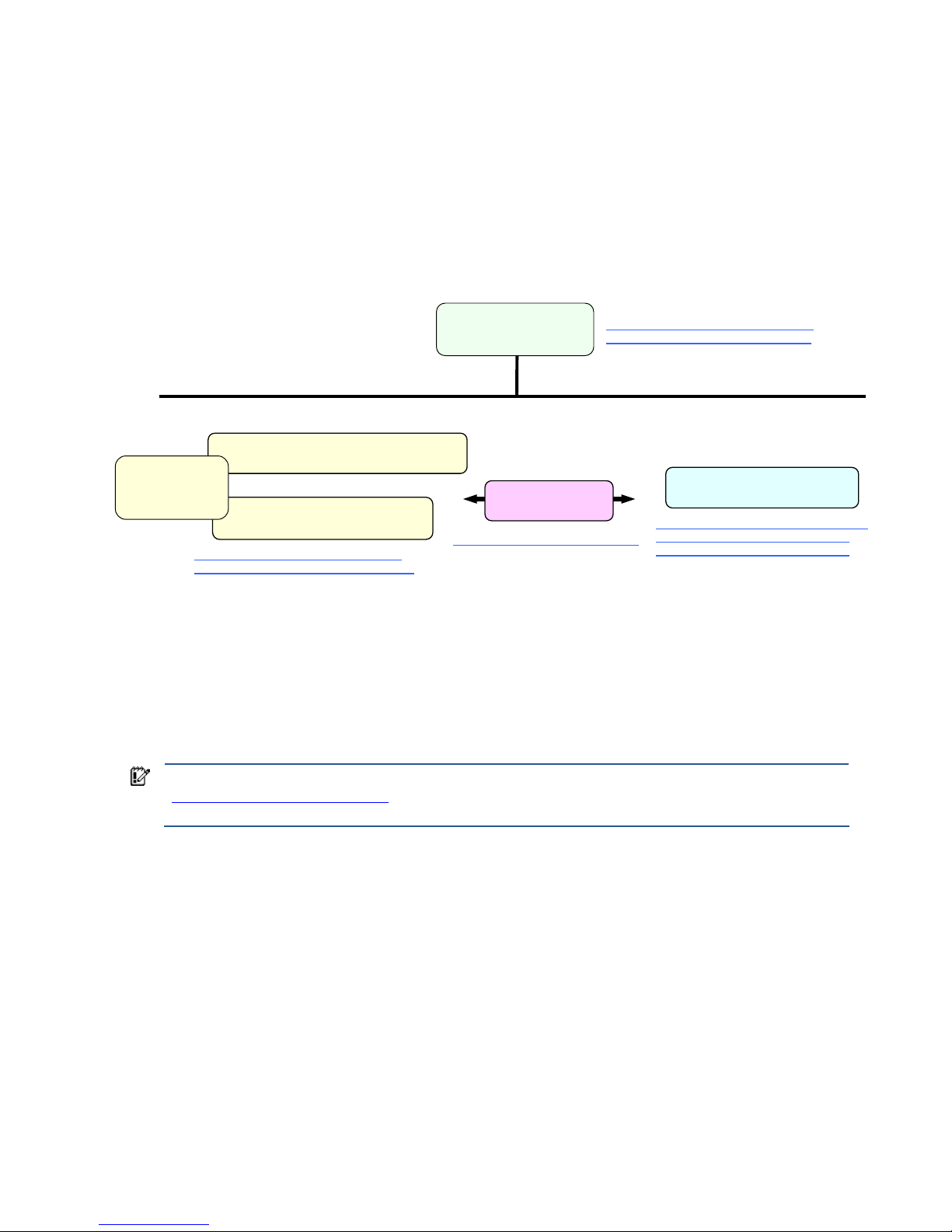
Figure 1-1 provides a simplified documentation hierarchy of the HP Blade Workstation Solution. The HP Blade
Workstation Solution Planning Guide is the top-most document in the documentation hierarchy, and, as noted
previously, is the recommended document to begin with. At the next level in the hierarchy are the documents
describing the following three building blocks of the blade workstation solution:
1. HP ProLiant Blade Workstations
2. HP Remote Graphics Software (HP RGS)
3. Client computers
Figure 1-1 Simplified HP Blade Workstation Solution documentation hierarchy
As shown in Figure 1-1, two Administrator’s Guides are available for the HP ProLiant Blade Workstations:
• Administrator’s Guide for Microsoft Windows on HP ProLiant Blade Workstations (this document)
• Administrator’s Guide for Linux on HP ProLiant Blade Workstations
Accompanying these Administrator’s Guides is the document Hardware and Software Supported by HP ProLiant
Blade Workstations. This document lists hardware that works with the blade workstation, such as network
switches and graphics cards. The document also lists software, such as manageability software, that is supported
by the blade workstation.
IMPORTANT: Windows Vista-32 recovery DVDs are shipped with the blade workstation. See Section 1-6,
“Ordering Windows recovery media,” for information on ordering Windows XP-32 and Windows Vista-64
recovery media.
The primary Remote Graphics Software document is the HP Remote Graphics Software User Guide. The client
computers are described in the HP Blade Workstation Client series – Embedded OS Version 9.xx manual. These
documents, and many others, are available on the websites listed in Figure 1-1. Please visit these websites to
view all blade workstation solution documents.
HP Remote Graphics
Software User Guide
HP Blade Workstation
Solution Planning Guide
Administrator’s Guide for Microsoft Windows
on HP ProLiant Blade Workstations
Administrator’s Guide for Linux
on HP ProLiant Blade Workstations
HP Blade Workstation Client series -Embedded OS Version 9.xx
HP ProLiant Blade Workstations
HP RGS
client computers
www.hp.com/support/rgs_manuals
www.hp.com/support/bwclient_manuals
www.hp.com/support/dc72_manuals
www.hp.com/support/dc73_manuals
www.hp.com/support/xw460c_manuals,
www.hp.com/support/xw2x220c_manu
als
This
document
Hardware and
Software Supported
by HP ProLiant
Blade Workstations
www.hp.com/support/xw460c_manuals,
www.hp.com/support/xw2x220c_manuals

Introduction 12
1-4 Obtaining HP technical support
If you encounter an issue that requires technical support, please do the following prior to contacting HP for
assistance:
• Be near your blade workstation
• Have available your blade workstation serial number, product number, and model name
• Note the following:
• Error messages
• Add-on options
• Operating system
• Third-party hardware or software
• Blinking LEDs on the blade workstation
• Applications you were using when you encountered the issue
• Be prepared to spend the time necessary to troubleshoot the problem with support personnel
To find your HP support center phone number, visit the HP website at
welcome.hp.com/country/us/en/wwcontact_us.html
. Select your region, and click the Technical support after
you buy link under the Call HP heading to obtain the support center phone number for your region.
In North America, call 800-HP Invent (800-474-6836). As of the date this document was published, providing
the following voice responses will connect you to the appropriate support personnel:
1. “technical support”
2. “software”
3. “workstation”
4. “blade workstation”
You’ll be asked for your blade workstation model number and serial number.
1-5 Customer Self Repair
HP ProLiant Blade Workstations are designed with many Customer Self Repair parts to minimize repair time, and
allow for greater flexibility in replacing defective parts. For information on Customer Self Repair for your blade
workstation, please see the following documents:
HP ProLiant xw460c Blade Workstation Maintenance and Service Guide at www.hp.com/support/xw460c_manuals
HP ProLiant xw2x220c Blade Workstation Maintenance and Service Guide at www.hp.com/support/xw2x220c_manuals
1-6 Ordering Windows recovery media
Recovery media is available for the following operating systems:
• Windows XP-32
• Windows Vista-32 (recovery media for Windows Vista-32 is included with your blade workstation)
• Windows Vista-64
To order recovery media in North America, call the HP Order Center at 800-952-7689 (US) or 800-567-1616
(Canada). Outside of North America, call your HP support center as described in Section 1-4.
1-7 Microsoft Windows licensing
The HP ProLiant Blade Workstations include a license for Microsoft Windows Vista Business Blade PC Edition.
The functionality of the Blade PC Edition is identical to the respective standard OS version but differs in the
licensing terms.
For example, the Blade PC Edition is licensed only for blade workstations, not conventional desktop systems.
However, Microsoft Volume License customers can use their XP Professional or Vista Business or Enterprise
Volume License bits on blade workstations because the binary code is the same as the respective Blade PC
Edition.

Introduction 13
Another difference between the Blade PC Editions and the standard Microsoft Windows OS versions is that the
Blade PC Editions includes a single Remote Desktop License (RDL). Ensure that you review and adhere to the RDL.
For more information, refer to the Microsoft Windows XP Professional Blade PC Edition End User License
Agreement (EULA) or the Windows Vista Business Blade PC Edition Licensing Terms, as appropriate. Contact
legal counsel to determine your rights and responsibilities under this license.
Blade workstations purchased with the Genuine Windows Vista® downgrade to Genuine Microsoft® Windows®
XP Professional option include a license for Microsoft Windows Vista™ Business Blade PC Edition. The Vista OS
installed on the system disk has been downgraded in the factory to Microsoft Windows XP Professional Blade PC
Edition in accordance with your rights under the Microsoft License Terms for Microsoft Windows Vista™ Business
Blade PC Edition. The Blade PC Editions of both operating systems are identical to the usual corresponding
Business/Professional OS, but differ in their licensing terms.
Blade workstation video subsystem 14
2 Blade workstation video subsystem
This chapter describes the blade workstation video subsystem. Because the blade workstation contains two types
of video controllers, it is important to understand their functionality and operating modes. The two types of video
controllers are:
• ATI RN50 video controller (“ATI video controller”)—The ATI Video controller is built-into the blade
workstation.
• NVIDIA Quadro FX graphics adapter (“NVIDIA graphics adapter”)—The xw460c blade workstation
supports a number of NVIDIA graphics adapters, either in single-card configurations or dual-card
configurations. See the document Hardware and Software Supported by HP ProLiant Blade Workstations
for a description of the NVIDIA graphics adapters supported by the xw460c blade workstation, as well as
whether they are supported in single-card or dual-card configurations.
The xw2x220c blade workstation supports only a single type of NVIDIA graphics adapter; again, see the
document Hardware and Software Supported by HP ProLiant Blade Workstations for a description of the
NVIDIA graphics adapter supported by the xw2x220c blade workstation
In September 2008, HP began offering the HP Graphics Expansion Blade (“expansion blade”), which attaches to
the xw460c blade workstation only. The expansion blade supports the installation of certain PCI-Express NVIDIA
Quadro FX graphics adapters. Again, see Hardware and Software Supported by HP ProLiant Blade Workstations
for a description of the PCI-Express NVIDIA graphics adapters that can be installed in the expansion blade (as
well as the NVIDIA graphics adapters that can be installed internal to the blade workstation). Note that the
expansion blade does not currently support dual graphics—that is, only one PCI-Express graphics adapter can be
installed in the expansion blade.
NOTE: NVIDIA graphics adapters are installed internal to the xw460c blade workstation if an expansion
blade is not attached to the blade workstation. If an expansion blade is attached, graphics adapters can only
be installed in the expansion blade, not internal to the blade workstation. Unless otherwise noted, no
distinction is made in this chapter based on where the graphics adapter(s) are installed—internal to the
xw460c blade workstation or in the expansion blade—because their installation location is invisible to
Windows.
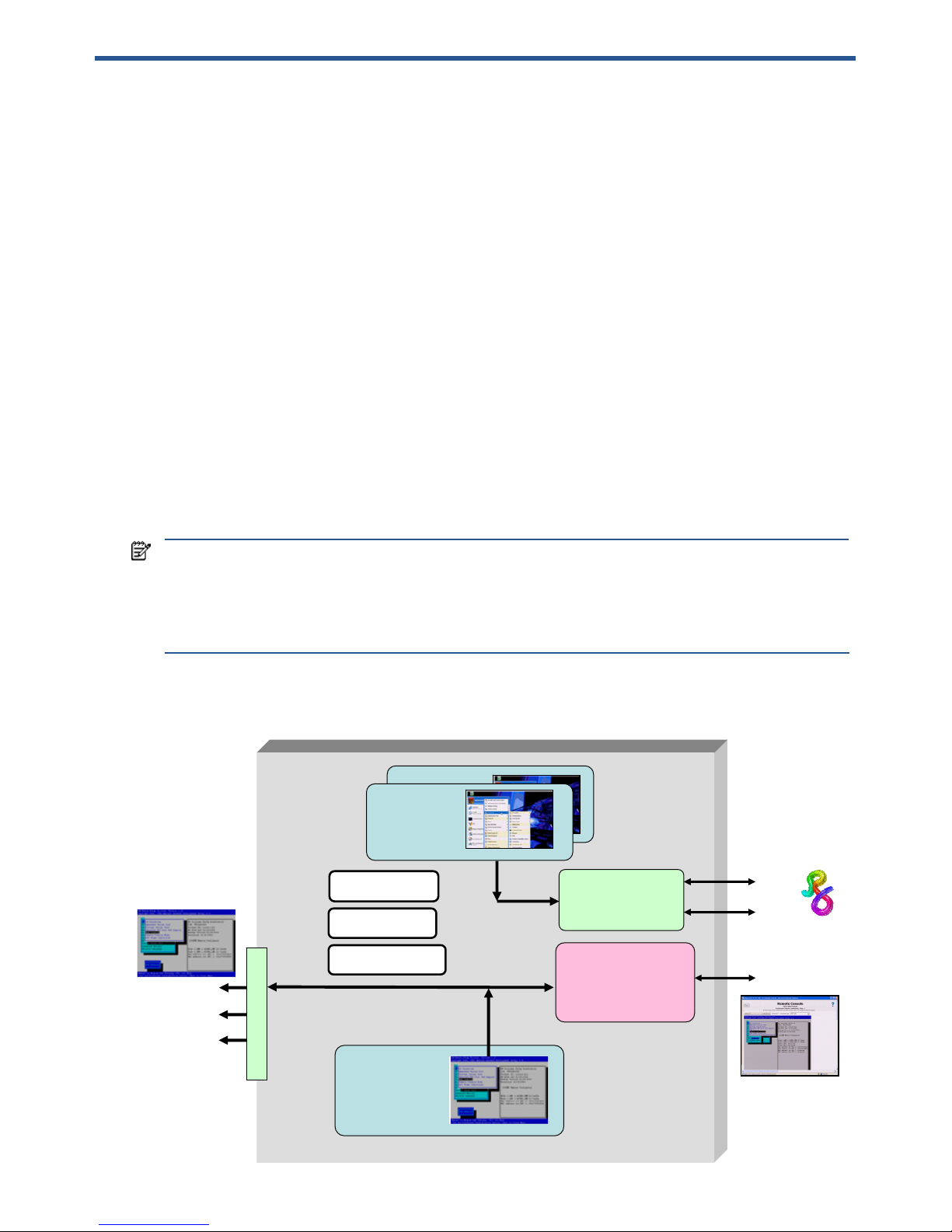
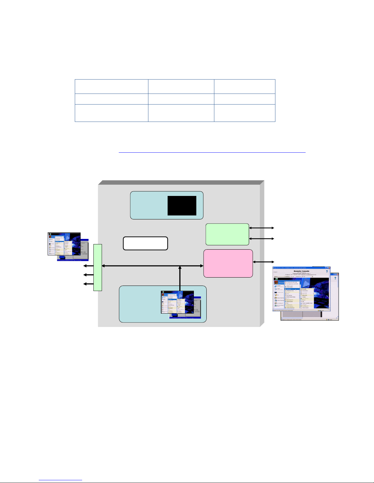
Figure 2-1 shows the blade workstation video subsystem architecture, and lists the three operating modes.
Figure 2-1 Video subsystem architecture and operating modes
Dual Broadcom
5708s Ethernet
controllers
iLO 2
management
processor
ATI RN50
video controller
(1280 x 1024)
NIC 1
NIC 2
iLO 2
Admin Mode
User Mode
Setup Mode
video
USB x 2
serial
Local I/O Connector
NVIDIA Quadro
FX graphics
adapter
NVIDIA Quadro
FX graphics
adapter
Boot console
Windows desktop
in Admin Mode
and Setup Mode
Windows desktop
in User Mode
One or two
graphics
adapters

Blade workstation video subsystem 15
The key features of the video subsystem are:
• The blade workstation boot console is always generated by the ATI video controller. The boot console can
be viewed either by connecting a monitor to the video output of the Local I/O Connector, or can be viewed
over the network using the iLO 2 Ethernet port, as shown in Figure 2-1.
• The Windows desktop typically runs on the NVIDIA graphics adapter.
• Viewing of the Windows desktop on internally-installed NVIDIA graphics adapter(s) is performed using
RGS—there is no video connector on the blade workstation to allow direct viewing of the video from
NVIDIA graphics adapter(s) installed internal to the blade workstation.
• Operation of the blade workstation ATI video controller and NVIDIA graphics adapter is governed by the
BIOS parameter Remote Console Mode, which can be set to the following three modes:
1. Admin Mode
2. User Mode (default setting)
3. Setup Mode
The following sections describe how to set Remote Console Mode, and how the setting affects display of the
Windows desktop.
NOTE: Remote Console Mode is different than the iLO 2 Remote Console. Remote Console Mode is a BIOS
setting while iLO 2 Remote Console is a means of viewing blade operation through the iLO 2 network port.
Blade workstation video subsystem 16
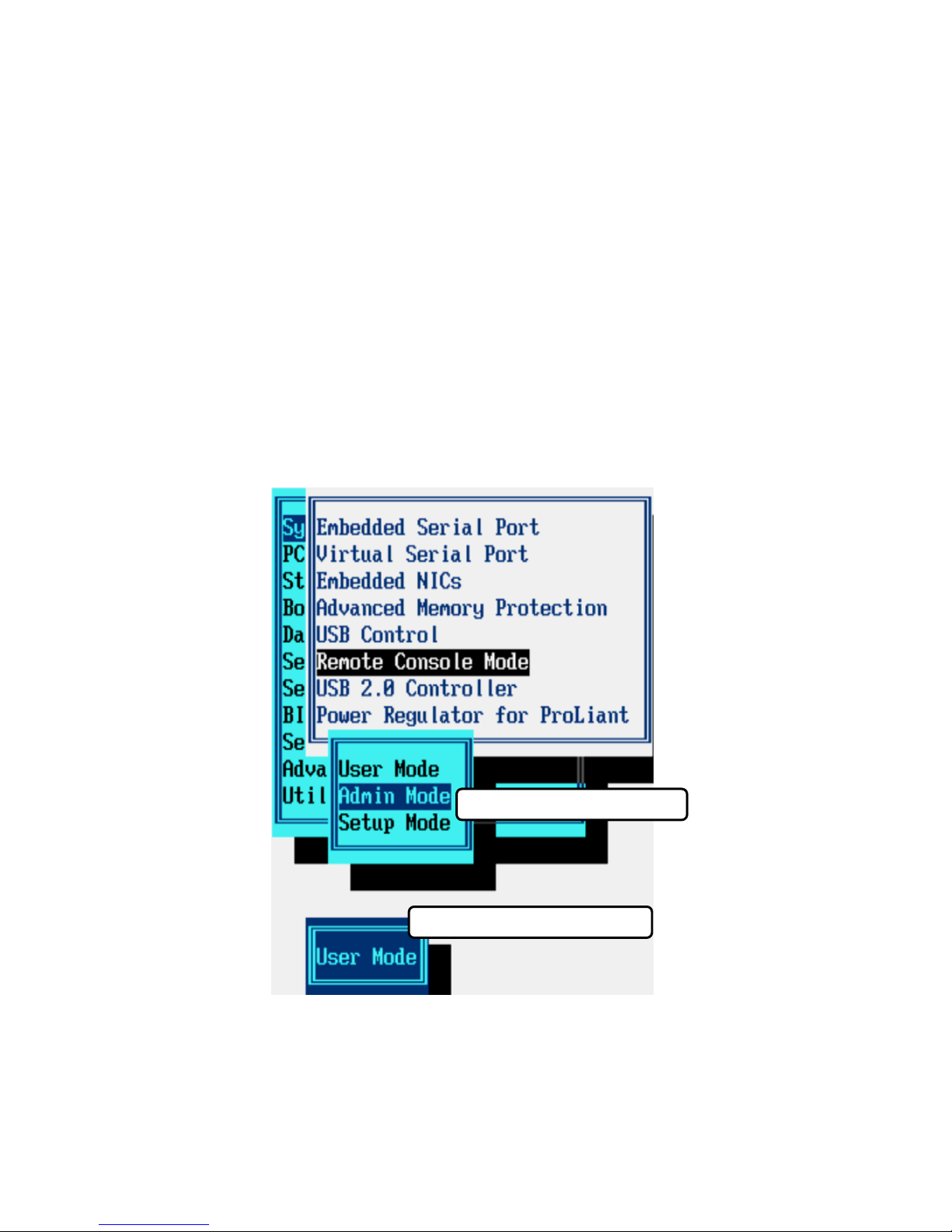
2-1 Setting Remote Console Mode
Remote Console Mode can be viewed or changed during the Power-On Self Test (POST) phase. During POST,
the boot console is generated by the ATI video controller in all three Remote Console Modes, as shown in Figure
2-1. To view or set Remote Console Mode during booting, perform the following steps:
1. Establish a means of viewing the boot console using either the Local I/O Connector or the iLO 2 Ethernet
port. Using iLO 2 is typically more convenient than using the Local I/O Connector, and also provides direct
control of the blade workstation power.
2. Initiate a restart of the blade workstation. Press the F9 key on your keyboard when prompted during
booting. This will bring up the ROM-based Setup Utility (see Figure 2-2).
3. Select System Options -> Remote Console Mode, which will display the current Remote Console Mode. In
Figure 2-2, the current Remote Console Mode is User Mode.
4. To change the Remote Console Mode, press Enter to bring up the Remote Console Mode menu, and then
use your Up and Down arrow keys to select the desired mode. In Figure 2-2, Admin Mode has been
selected. Press Enter when done, and perform the steps indicated to exit the ROM-based Setup Utility.
5. The blade workstation will automatically perform a reboot, and will come up in the Remote Console Mode
that you selected.
Figure 2-2 Viewing and setting Remote Console Mode
Current Remote Console Mode
Remote Console Mode menu
Blade workstation video subsystem 17
2-2 Admin Mode
When Remote Console Mode is set to Admin Mode, the ATI video controller first generates the boot console
during Power-on Self Test (POST), and then generates the Windows desktop (see Table 2-1 and Figure 2-3). In
this mode, the NVIDIA graphics adapter is not visible to Windows, and is not used.
Table 2-1 Use of the video controllers in Admin Mode
Usage during POST Usage after booting
ATI video controller Boot console Windows desktop
NVIDIA graphics adapter Not used Invisible to Windows
Figure 2-3 Admin Mode
In Admin Mode, the boot console and the Windows desktop generated by the ATI video controller can be
viewed in two ways:
• Using a monitor connected to the Local I/O Connector video signal
• Using the iLO 2 Remote Console by pointing your browser to the iLO 2 IP address
NVIDIA Quadro
FX graphics
adapter
Dual Broadcom
5708 Ethernet
controllers
iLO 2
management
processor
ATI RN50
video controller
(1280 x 1024)
NIC 1
NIC 2
iLO 2
First the boot console
and then the Windows
desktop are generated
by the ATI video
controller
NVIDIA graphics
adapter is not visible
to Windows
Admin Mode
video
USB x 2
serial
Local I/O Connector
Windows desktop
Boot console
Windows desktop
Boot console
Blade workstation video subsystem 18
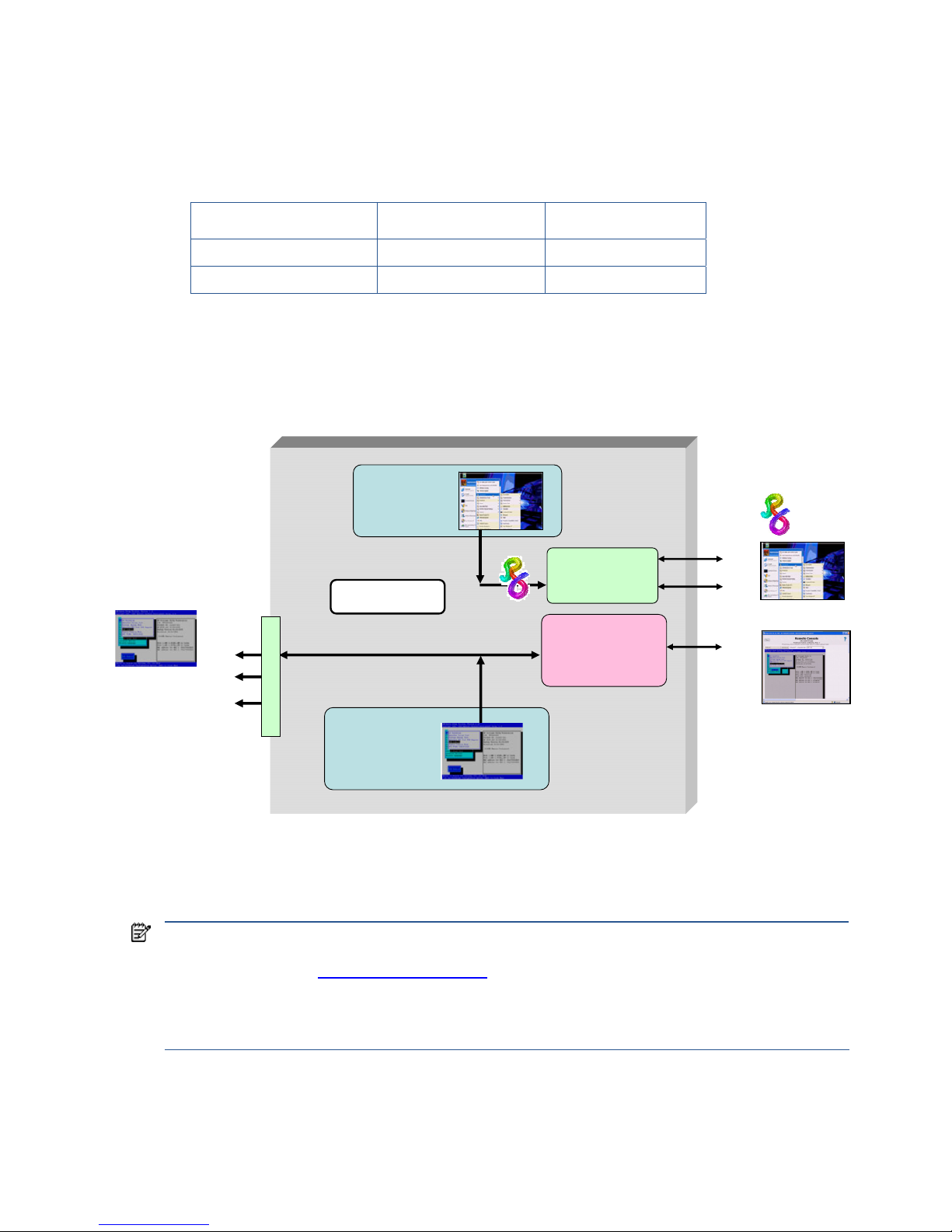
2-3 Setup Mode
Setup Mode is very similar to Admin Mode—the ATI video controller first generates the boot console and then
generates the Windows desktop (see Table 2-2 and Figure 2-4). In Setup Mode, however, the NVIDIA graphics
adapter, although it isn’t used, is visible to Windows.
Table 2-2 Use of the video controllers in Setup Mode
Usage during POST Usage after booting
ATI video controller Boot console Windows desktop
NVIDIA graphics adapter Not used
Not used but is
visible to Windows
Visibility of the NVIDIA graphics adapter allows the Windows operating system to install the NVIDIA graphics
adapter driver the first time the blade workstation boots. For more information about the initial blade workstation
boot, see Chapter 3, “Installing, powering on, booting, and validating the blade workstation solution.”
Figure 2-4 Setup Mode
In Setup Mode, as with Admin Mode, the Windows desktop can be viewed in two ways:
• Using a monitor connected to the Local I/O Connector video signal
• Using the iLO 2 Remote Console by pointing your browser to the iLO 2 IP address
NVIDIA Quadro
FX graphics
adapter
Dual Broadcom
5708 Ethernet
controllers
iLO 2
management
processor
ATI RN50
video controller
(1280 x 1024)
NIC 1
NIC 2
iLO 2
NVIDIA graphics
adapter is visible
to the operating
system
Setup Mode
video
USB x 2
serial
Local I/O Connector
Windows desktop
Boot console
First the boot console
and then the Windows
desktop are generated
by the ATI video
controller
Windows desktop
Boot console
Blade workstation video subsystem 19
2-4 User Mode
When Remote Console Mode is set to User Mode, the boot console is, as usual, generated by the ATI video
controller. Following the booting of Windows, the NVIDIA graphics adapter generates the Windows desktop
(see Table 2-3 and Figure 2-5).
Table 2-3 Use of the video controllers in User Mode
Usage during POST Usage after booting
ATI video controller Boot console Not used
NVIDIA graphics adapter Note used Windows desktop
In User Mode, the Windows desktop can only be viewed using RGS through NIC1 or NIC2. Because the ATI
video controller is inactive after Windows starts, the Windows desktop is not viewable on the Local I/O
Connector or through iLO 2.
Figure 2-5 User Mode
As noted previously, the default setting of Remote Console Mode is User Mode. This enables custom Windows
images (loaded through processes such as PXE booting) to boot directly into User Mode without needing to
change Remote Console Mode from its default setting.
NOTE: In addition to viewing the Windows desktop generated by one of the video controllers, the Windows
desktop can also be viewed using Microsoft Remote Desktop Connection (RDC). For more information about
RDC, see Section 12-3, “Remote Desktop Connection
.”
These viewing methods cannot be used simultaneously. If RDC is started, the Windows desktop session
provided by the video controller is terminated and returns to a Windows login screen. If the user logs into
Windows while RDC is active, the RDC connection is terminated.
Dual Broadcom
5708 Ethernet
controllers
iLO 2
management
processor
ATI RN50
video controller
(1280 x 1024)
NIC 1
NIC 2
iLO 2
NVIDIA Quadro
FX graphics
adapter
Windows
desktop
User Mode
The ATI video controller
is used during booting
but is not used after
Windows starts.
video
USB x 2
serial
Local I/O Connector

Blade workstation video subsystem 20
2-5 Summary of Remote Console Modes
Table 2-4 summarizes the use of the video controllers in the three Remote Console Modes—Admin Mode, Setup
Mode, and User Mode. The video controller used during booting is highlighted in green, showing that the ATI
video controller is used in all three Remote Console Modes to display the boot console during Power-on Self Test
(POST). The video controller used for the Windows desktop is highlighted in blue, showing that the ATI video
controller is used in Admin and Setup Modes, while the NVIDIA graphics adapter is used in User Mode.
Table 2-4 Use of the video controllers for each Remote Console Mode
Remote Console
Mode
Video controller
Usage during POST Usage after booting
ATI video controller
Boot console Windows desktop
Admin Mode
NVIDIA graphics adapter
Not used Invisible to Windows
ATI video controller
Boot console Windows desktop
Setup Mode
NVIDIA graphics adapter
Not used
Not used but is visible to
Windows. This enables the
NVIDIA graphics driver to
be installed the first time
Windows boots.
ATI video controller
Boot console Not used
User Mode
NVIDIA graphics adapter
Note used
Windows desktop

Installing, powering on, booting, and validating the blade workstation solution 21
3 Installing, powering on, booting, and validating the
blade workstation solution
This chapter describes the process to install, power on, boot and validate the HP Blade Workstation Solution. A
building block approach is followed, starting with a single blade workstation and a single client computer. After
validating their operation, other blade workstations and client computers can be integrated into the solution.
The seven steps of this approach are listed below. Note that Step 1 is independent of steps 2–4. You can
perform Step 1 first, or Steps 2-4 first.
1. Set up the client computer.
2. Install and power on the first blade workstation by performing these steps:
a. Prepare the blade enclosure & its networking infrastructure.
b. Configure the blade workstation hardware.
c. Install the blade workstation into the enclosure and boot Windows XP Professional.
3. Boot and configure the Windows XP-32 operating system
4. Verify network connections to the blade workstation Ethernet ports: NIC1, NIC2, and iLO 2.
5. Install RGS on the blade workstation, and verify RGS operation between the blade workstation and the
client computer.
6. Install the required applications on the blade workstation.
7. Validate the solution consisting of the blade workstation, its applications, RGS, and the client computer.
After validating the solution, you can integrate other blade workstations and client computers into the solution.
NOTE: In previous generations of blade workstations (such as the HP ProLiant xw25p Blade Workstation), it
was possible to power a blade workstation without installing it in an enclosure by using the HP Diagnostic
Station. However, the xw460c and xw2x220c blade workstations do not have such a diagnostic station—the
only way to power these blade workstations, and connect them to the network, is to install the blade
workstations and network interconnect devices in the c3000 or c7000 enclosure.
The installation, power on, and validation procedures are based on the following assumptions:
• You are using the factory-installed Windows XP-32 operating system. For more information about creating a
custom Windows XP image, see Chapter 4, “Creating and restoring the Windows XP operating system
.”
• A personal computer (PC) is available to verify network connectivity to the blade workstation and client
computer.
• You have access to the documentation listed in Section 1-3, “Blade workstation solution documentation
.”
• Power calculations have been performed to ensure there is sufficient power in the enclosure for the blades
and other equipment. For more information, see the HP website at
www.hp.com/go/bladesystem/powercalculator.
• Sufficient cooling is available for the c3000 or c7000 enclosure.
• You have characterized and designed your network infrastructure to accommodate the network
requirements of your blade workstations and client computers. The HP Blade Workstation Solution Planning
Guide referenced in Chapter 1 provides extensive information on optimizing your network.

Installing, powering on, booting, and validating the blade workstation solution 22
3-1 Setting up the client computer
If you are using one of the client computers in the HP Blade Workstation Client series, refer to the documentation
specific to your client computer, as described in Section 1-3, “Blade workstation solution documents.” RGS is
factory-installed on these client computers. If another client computer will be used, ensure that RGS (specifically,
the RGS Receiver) is installed on the computer, and is properly configured to establish a connection to the blade
workstation.
3-2 Installing and turning on the blade workstation
For an overview of the installation and turn on process, refer to the HP ProLiant xw460c Blade Workstation
Installation Instructions or the HP ProLiant xw2x220c Blade Workstation Installation Instructions. Because the
blade workstation shares many components with the server blade, the following server blade documents should
be referenced for details on the installation and turn on process (taking into account the enclosure that you’re
using):
• HP BladeSystem c7000 Enclosure Setup and Installation Guide
• Power Supply Installation Instructions for HP BladeSystem c7000 Enclosures
• HP BladeSystem c3000 Enclosure Setup and Installation Guide
• HP BladeSystem c3000 Tower Enclosure Setup and Installation Guide
• HP ProLiant BL460c Server Blade User Guide
• HP ProLiant BL2x220c Server Blade User Guide
• HP BladeSystem Onboard Administrator User Guide
• Integrated Lights-Out 2 User Guide
In addition, refer to your network interconnect device documentation.
3-2-1 Preparing the blade workstation infrastructure
To prepare the blade workstation infrastructure (enclosure, power supplies, Onboard Administrator modules, and
networking), perform the following steps:
1. To set up the enclosure, including wiring the Power Distribution Units (PDUs), follow the instructions in the
HP BladeSystem c7000 Enclosure Setup and Installation Guide.
2. Install power supplies in the enclosure according to the HP BladeSystem power guidelines on the HP
website at www.hp.com/go/bladesystem/powercalculator
.
3. Install the Onboard Administrator modules. If you are using multiple c3000 or c7000 enclosures, connect
the Onboard Administrator module in each enclosure to the uplink/downlink Ethernet connectors in each
module.
4. Install your network devices in the enclosure, and connect them to your site network infrastructure. The
document Hardware and Software Supported by HP ProLiant Blade Workstations describes the c7000
enclosure interconnect bay mappings for the xw460c blade workstation and the xw2x220c blade
workstation.
5. Connect power to the enclosure and turn it on. When the enclosure is powered up for the first time, Insight
Display launches an installation wizard to guide you in the configuration process. Complete the
configuration process and verify there are no installation or configuration errors that appear on the Insight
Display.
6. Verify the Onboard Administrator module and network devices can be accessed over the network from the
PC.
After completing the preceding steps, you should have a suitable environment for installing and powering on
your blade workstations.
Installing, powering on, booting, and validating the blade workstation solution 23
3-2-2 Configuring the blade workstation hardware
The blade workstation hardware listed below is configured before installing the blade in the enclosure. Unless
otherwise noted, the hardware listed below can be configured on both the xw460c and xw2x220c blade
workstations.
IMPORTANT: Refer to the document Hardware and Software Supported by HP ProLiant Blade Workstations for
more details on hardware configuration, as well as the latest information on supported hardware and software.
• Intel Xeon processors—The blade workstation supports either one or two Dual-Core or Quad-Core
processors, offering multiple frequencies of each processor type. In dual processor configurations, both
processors must have the same number of cores, and must operate at the same frequency. See the
document Hardware and Software Supported by HP ProLiant Blade Workstations for a description of the
processors that are available for each blade workstation.
• Memory—Up to eight memory DIMMs can be installed in the blade workstation, supporting up to 64 GB of
memory for the xw460c blade workstation and up to 32 GB for each workstation node with the xw2x220c
blade workstation. See the document Hardware and Software Supported by HP ProLiant Blade
Workstations for a description of per-OS memory limitations.
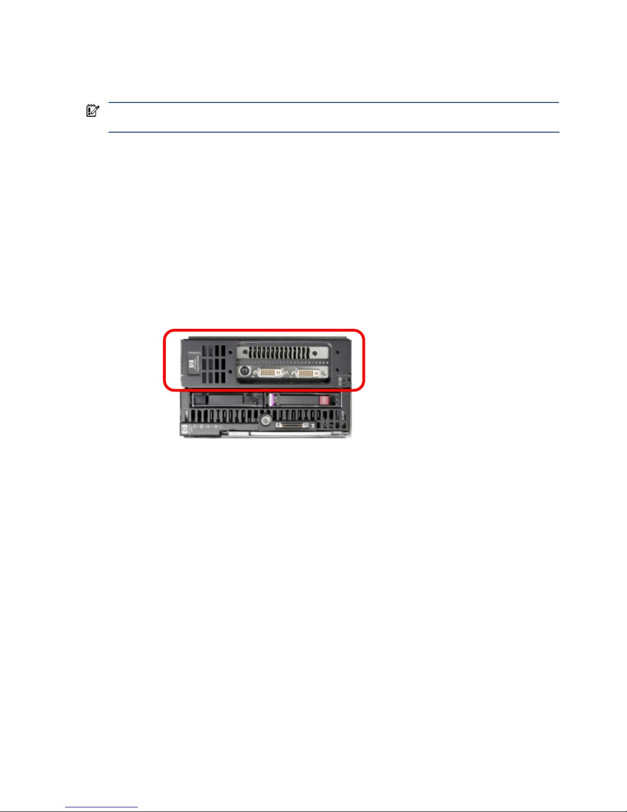
• HP Graphic Expansion Blade—The graphics expansion blade, circled in Figure 3-1, is supported as of
September 2008, on the xw460c blade workstation. The graphics expansion blade attaches to the top of
the blade workstation and accommodates a full length PCI-Express graphics card.
Figure 3-1 The HP Graphics Expansion Blade attaches to the xw460c blade workstation
The graphics expansion blade can only be purchased factory-attached to the blade workstation—it is not
currently available as a customer-installable option.
• NVIDIA Quadro FX graphics adapter—The xw460c blade workstation supports a number of graphics
adapters, which can be ordered factory-installed or as after market option kits. See the document Hardware
and Software Supported by HP ProLiant Blade Workstations for a list of the NVIDIA graphics adapters that
are available. The xw2x220c blade workstation supports only a single, factory-installed NVIDIA Quadro FX
770M graphics adapter per workstation node.
• Disk drives—The xw460c blade workstation supports one or two Serial Attached SCSI (SAS) disk drives,
with either 72 GB or 146 GB per drive. The xw2x220c blade workstation supports one 120 GB or one
250 GB SATA disk drive per workstation node.
• Storage controllers—The xw460c blade workstation can be ordered with either of these storage controllers:
• Storage controller with 64 MB of cache memory
• Storage controller with 128 MB of battery-backed write cache—This storage controller is the default
controller from the factory, and can also be ordered as a field upgrade.
The xw2x220c blade workstation is configured with one SATA storage controller per workstation node.
HP ProLiant xw460c
Blade Workstation
HP Graphics
Expansion Blade
Installing, powering on, booting, and validating the blade workstation solution 24
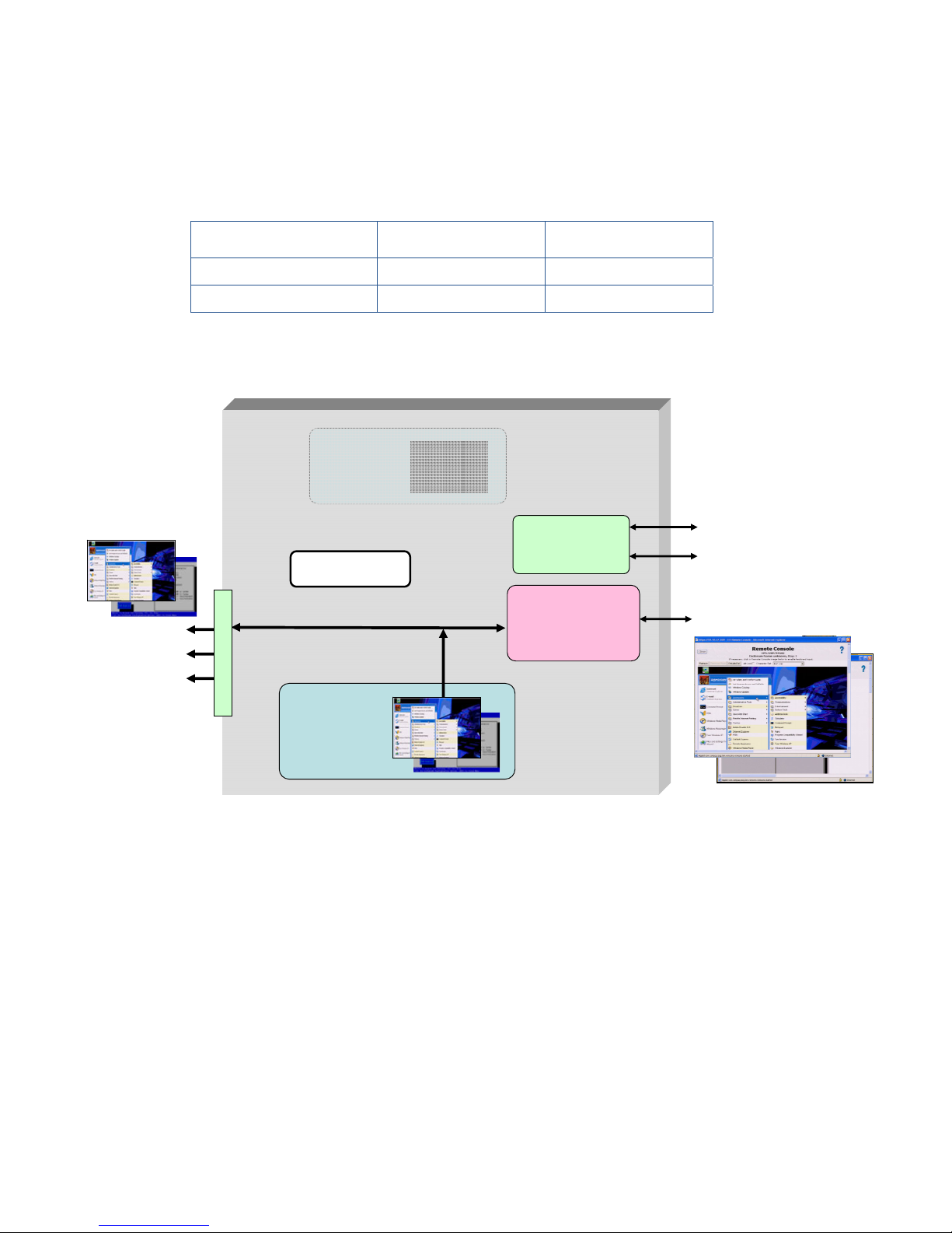
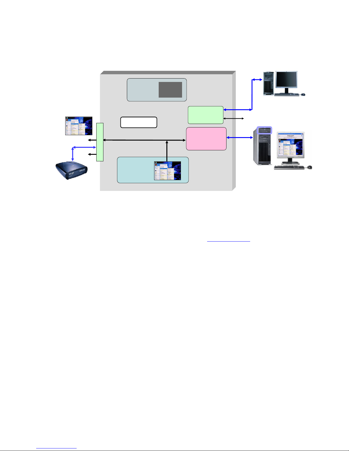
3-2-3 Connecting media to the blade workstation
The blade workstation architecture supports three primary methods of connecting media to the blade (such as a
CD/DVD drive). Figure 3-2 shows media connection in Admin Mode.
Figure 3-2 Connecting media to the blade workstation
The three methods of connecting media are:
• Connect media to one of the USB connectors on the Local I/O Cable
• Connect a shared network drive to the blade using Windows XP
• Use iLO 2 virtual media to mount PC media (such as a CD/DVD drive) to the blade workstation. For more
information about iLO 2 virtual media, see Section 12-2-4, “iLO 2 virtual media”.
In addition, the c3000 enclosure supports an optional DVD drive that can be used to install the operating system
or software on a blade workstation. Using the c3000 Onboard Administrator, the DVD drive can be attached to
any or all blade workstations in the enclosure.
Dual Broadcom
5708 Ethernet
controllers
iLO 2
management
processor
ATI RN50
video controller
(1280 x 1024)
NIC 1
NIC 2
iLO 2
Windows
Console
NVIDIA graphics
adapter is not visible
to the operating
system
Admin Mode
CD/DVD drive
iLO 2 virtual media
shared network drive
Virtual CD/DVD
NVIDIA Quadro
FX graphics
adapter
128 MB
USB x 2
local I/O connector
video
serial
Installing, powering on, booting, and validating the blade workstation solution 25
3-2-4 Powering on the blade workstation
This section describes how to power on the blade workstation using the factory-installed Microsoft Windows XP32 operating system.
NOTE: The blade power on process can be performed using either the Local I/O Cable or iLO 2 Remote
Console. The advantage of using the Local I/O Cable is that blade verification is not dependent on iLO 2
networking (which, by default, requires a DHCP server to assign the IP address). Using the Local I/O Cable,
you can confirm that the iLO 2 IP address is set as expected—at that point, you have the option of using the
iLO 2 Remote Console.
HP recommends using the Local I/O Cable to power on the first blade workstation. Once it has been verified
(including DHCP assignment of the NIC1, NIC2, and iLO 2 IP addresses), subsequent blade workstations can
be powered on using the iLO 2 Remote Console. This is consistent with the building block approach—start
simple, and build from there. Therefore, the following steps are based on using the Local I/O Cable.
To power on the blade workstation, perform the following steps:
1. Install the blade workstation in the c3000 or c7000 enclosure. Because the blade is hot-pluggable, it can
be inserted and removed while the enclosure is powered.
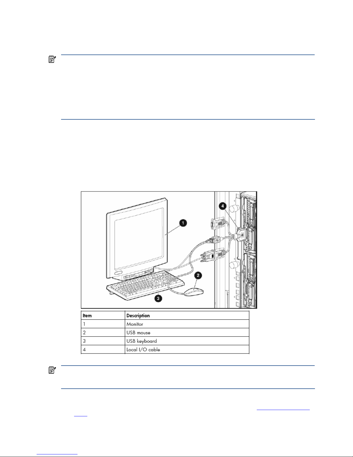
2. Connect the Local I/O Cable to the Local I/O Connector on the front of the blade workstation. Connect a
monitor, USB keyboard, and USB mouse to the Local I/O Cable (see Figure 3-3). Note that the xw2x220c
blade workstation has two Local I/O Connectors, one for Workstation A and one for Workstation B.
Figure 3-3 Connecting a monitor, keyboard, and mouse to the blade workstation
NOTE: Depending on how you interact with the blade workstation and how many USB devices you have
connected to the Local I/O Cable (such as a keyboard and mouse), it might be necessary to add a USB hub to
connect additional USB devices, such as a USB CD/DVD drive.
3. Power on the blade by pressing the front panel Power On button. The boot sequence is displayed on the
monitor. Set Remote Console Mode to Setup Mode as described in Section 2-1, “Setting Remote Console
Mode”. Save the BIOS setting, and continue with the boot process.
Installing, powering on, booting, and validating the blade workstation solution 26
3-2-5 Blade workstation sleep states
The blade workstation supports two sleep states: S0 (fully on) and S5 (off but connected to power). No other
power management states (such as Hibernate or Standby) should be used. From sleep state S5, Wake-on-LAN
(WOL) is supported by both NIC1 and NIC2. However, a blade workstation in sleep state s5 will be unable to
respond to an RGS connection request from a client computer, which will result in an RGS connection failure
being displayed on the client computer. Once Wake-on-LAN occurs and the blade workstation boots into
Windows, an RGS connection can be established by the client computer.
3-3 The OOBE screens
When the blade workstation boots the first time, it cycles through a number of OOBE (Out of Box Experience)
screens. These screens enable you to configure several Windows parameters, including:
• Region, keyboard layout, and input language
• Time zone
• End User License Agreement
• Automatic Updates (enable or disable)
• Computer name
• Administrator password
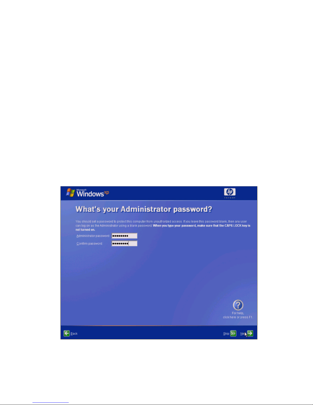
During the OOBE configuration process, the Administrator password screen is displayed (see Figure 3-4). It is
very important to set an Administrator password. Without an Administrator password, RGS cannot authenticate,
and no client connection is possible through an administrator account.
Figure 3-4 The OOBE Administrator password screen
After completing the OOBE process, the blade workstation reboots into Windows.
Installing, powering on, booting, and validating the blade workstation solution 27
3-4 Verifying networking
The next step is to verify that the blade workstation is accessible over the network using NIC1, NIC2, and iLO 2.
By default, the NIC1, NIC2, and iLO 2 IP addresses are set by DHCP. Therefore, ensure that the blade
workstation can connect to a DHCP server.
NOTE: The following steps are based on continued use of a keyboard, mouse, and monitor connected to the
Local I/O Cable.
3-4-1 NIC1 and NIC2 verification
The ipconfig command should be used to verify that the NIC1 and NIC2 IP addresses have been set by
DHCP. Alternatively, you can specify a static IP address and Subnet mask for each NIC.
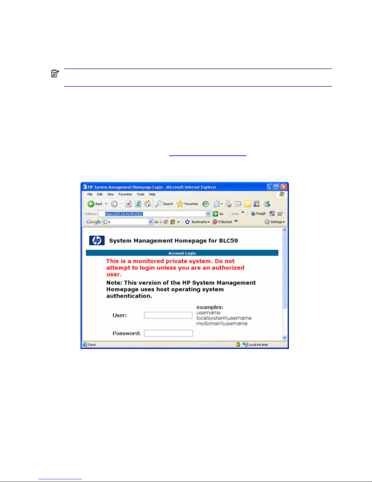
The simplest way to verify NIC1 and NIC2 operation is to access the blade System Management Homepage
(SMH) from your PC. To verify NIC1 and NIC2, point a browser window at each of their IP addresses using
HTTPS protocol and port 2381 (see Figure 3-5). The SMH page should appear using each NIC. For more
information about SMH, see Section 12-4, “System Management Homepage
.”
Figure 3-5 System Management Homepage

Installing, powering on, booting, and validating the blade workstation solution 28
3-4-2 iLO 2 network verification
To validate iLO 2 network access, you first need to know the iLO 2 IP address. There are several ways to
determine this:
• Reboot the blade. During the reboot, the boot console displays the iLO 2 IP address, as shown in Figure 3-6
(10.10.42.60).
Figure 3-6 Boot console display of the iLO 2 IP address
• Log into SMH, and click Embedded NEC98431 under Management Processor, which displays the iLO 2 IP
address.
• Use Onboard Administrator, as described in Section 12-1, “Onboard Administrator
.”
To validate iLO 2 network access, point your PC browser window to the iLO 2 IP address (again, using HTTPS).
This should display the login screen shown in Figure 3-7. For more information about iLO 2, see Section 12-2,
“Integrated Lights-Out 2 (iLO 2)
.”
Figure 3-7 iLO 2 login screen
Installing, powering on, booting, and validating the blade workstation solution 29
3-5 Installing, configuring, and verifying RGS
3-5-1 Installing RGS
RGS (specifically, the RGS Sender) is not factory-installed on the blade workstation. RGS needs to be obtained
from HP, and installed on your blade workstation. A paper License Agreement Certificate is shipped with your
blade workstation that allows you to download RGS 5.1.5 at no cost from HP—see the certificate for
downloading instructions.
Alternatively, you can purchase and install RGS 5.2.0 or later. To purchase RGS 5.2.0, start at the RGS
homepage at www.hp.com/go/rgs
. RGS 5.2.0 and later require installation of a license to operate—for
licensing details, see the HP RGS Licensing Guide, available on the RGS homepage.
Assuming you’ll first download RGS to your PC (not directly to the blade workstation), the RGS Sender installation
software can be made accessible by the blade workstation in several ways, including:
• Map the blade workstation C: drive to your PC, and then copy the RGS files to the blade workstation drive.
• Copy the RGS software to a CD, and then use iLO 2 virtual media from your PC to make the CD accessible
by the blade workstation. For information about iLO 2 virtual media, see Section 12-2-4, “iLO 2 virtual
media”.
Included with the RGS download is the HP Remote Graphics User Guide—refer to this document for detailed
installation instructions. Microsoft Remote Desktop Connection can be used to remotely install the RGS Sender.
IMPORTANT: RGS supports remote USB, which allows USB devices connected to the client computer to be
attached to the blade workstation. This enables the blade workstation to access the USB devices as if they are
connected directly to the blade workstation. During RGS installation, you’ll be asked whether you’d like to
enable remote USB. If you decide later to change remote USB (for example, to enable it from a disabled state),
you’ll need uninstall and reinstall the RGS Sender.
3-5-2 Setting the RGS NIC binding order
Because the blade workstation (the RGS Sender) has two network ports (NIC1 and NIC2), care must be
exercised when establishing a connection from the client computer (the RGS Receiver). It’s possible for the RGS
Sender to be “listening” on one NIC while the RGS Receiver is trying to establish a connection on the other NIC.
The RGS Sender binds to the first NIC detected during booting. To determine the IP address of the first NIC,
perform the following steps on the blade workstation:
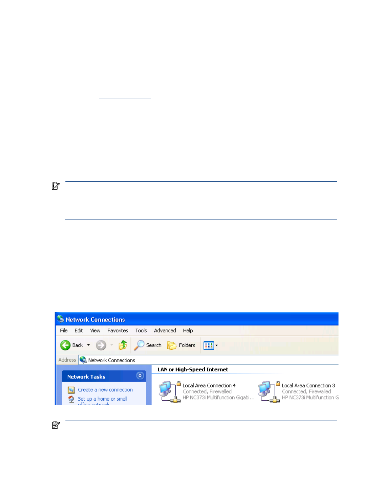
1. To view both NICs, click start > Control Panel > Network Connections (see Figure 3-8).
Figure 3-8 Viewing the two blade workstation NICs
NOTE: The xw460c blade workstation NICs are based on a pair of Broadcom 5708s Ethernet controllers. An
earlier naming convention referred to these controllers as “HP NC373i”, as shown in Figure 3-8. Subsequently,
the naming convention of “Broadcom BCM5708S” was adopted. Independent of the naming convention, the
Ethernet hardware is the same—dual Broadcom 5708s Ethernet controllers.
Installing, powering on, booting, and validating the blade workstation solution 30
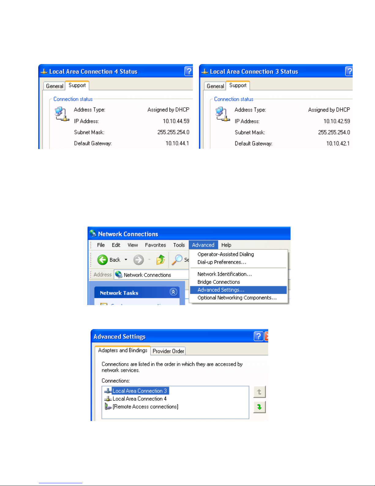
2. Double-click each LAN icon and the Support tab, which displays the IP address of each NIC (see Figure
3-9). While this provides the IP address of each NIC, it does not indicate which NIC is considered the
“first” NIC.
Figure 3-9 NIC IP addresses
3. To determine which NIC is the first NIC, click Advanced > Advanced Setting in the Network Connections
window (see Figure 3-10). The Advanced Settings window is displayed (see Figure 3-11). The “first” NIC is
listed at the top in the Connections box. In Figure 3-11, the first NIC is Local Area Connection 3, which
(from Figure 3-9) has an IP address of 10.10.42.59. This is the NIC that the blade workstation will be
“listening” to for an RGS connection.
Figure 3-10 Determining the first NIC
Figure 3-11 Advanced Settings dialog
The arrows to the right of the Connections box in Figure 3-11 can be used to change the order of the NICs to
specify which NIC will be used by the RGS Sender. In the example in Figure 3-11, the RGS Sender will use Local
Area Connection 3 with an IP address of 10.10.42.59.
 Loading...