

Page 1

HP ProLiant BL25p Server Blade Maintenance and Service Guide
December 2005 (Fourth Edition)
Part Number 377851-004A
Page 2

© Copyright 2005 Hewlett-Packard Development Company, L.P.
The information contained herein is subject to change without notice. The only warranties for HP products and services are set forth in the express
warranty statements accompanying such products and services. Nothing herein should be construed as constituting an additional warranty. HP
shall not be liable for technical or editorial errors or omissions contained herein.
Microsoft and Windows are U.S. registered trademarks of Microsoft Corporation.
Linux is a U.S. registered trademark of Linus Torvalds.
AMD Opteron is a trademark of Advanced Micro Devices, Inc.
December 2005 (Fourth Edition)
Part Number 377851-004A
Audience assumptions
This guide is for an experienced service technician. HP assumes you are qualified in the servicing of
computer equipment and trained in recognizing hazards in products with hazardous energy levels and
are familiar with weight and stability precautions for rack installations.
Page 3

Contents
Illustrated parts catalog ................................................................................................................. 5
Customer self repair................................................................................................................................... 5
Server blade components ........................................................................................................................... 6
Removal and replacement procedures............................................................................................. 8
Safety considerations.................................................................................................................................8
Preventing electrostatic discharge ...................................................................................................... 8
Server blade warnings and cautions ..................................................................................................9
Rack warnings and cautions .............................................................................................................9
Symbols on equipment ................................................................................................................... 10
Server blade preparation .........................................................................................................................11
Access panel .......................................................................................................................................... 12
Hard drives ............................................................................................................................................ 12
DIMMs................................................................................................................................................... 13
Processor ...............................................................................................................................................14
HP Smart Array 6i Controller .................................................................................................................... 17
HP Smart Array 6i battery-backed write cache enabler (optional) .................................................................. 18
Air baffle ............................................................................................................................................... 18
Fan assembly.......................................................................................................................................... 19
Fibre Channel mezzanine (optional) ..........................................................................................................20
Standard NIC mezzanine card .................................................................................................................21
SCSI backplane ...................................................................................................................................... 22
Power converter module........................................................................................................................... 23
DC filter module...................................................................................................................................... 23
Power button/LED board..........................................................................................................................24
System board battery............................................................................................................................... 25
System board ......................................................................................................................................... 26
Server blade bay blank............................................................................................................................ 28
Diagnostic tools.......................................................................................................................... 29
HP Insight Diagnostics.............................................................................................................................. 29
Survey Utility .......................................................................................................................................... 29
Integrated Management Log ..................................................................................................................... 29
Server component identification.................................................................................................... 31
Front panel components ........................................................................................................................... 31
Front panel LEDs ..................................................................................................................................... 32
Rear panel components............................................................................................................................ 33
Internal components................................................................................................................................. 34
System maintenance switch....................................................................................................................... 35
System maintenance switch procedures...................................................................................................... 35
Clearing the system configuration .................................................................................................... 35
Accessing the redundant ROM........................................................................................................ 36
Local I/O cable ......................................................................................................................................36
Hot-plug SCSI hard drive LEDs ..................................................................................................................37
Hot-plug SCSI hard drive LED combinations ................................................................................................ 37
Specifications............................................................................................................................. 39
Environmental specifications ..................................................................................................................... 39
Server specifications................................................................................................................................39
Acronyms and abbreviations........................................................................................................ 40
Contents 3
Page 4

Index......................................................................................................................................... 42
Contents 4
Page 5

Illustrated parts catalog
In this section
Customer self repair ................................................................................................................................. 5
Server blade components.......................................................................................................................... 6
Customer self repair
What is customer self repair?
HP's customer self-repair program offers you the fastest service under either warranty or contract. It
enables HP to ship replacement parts directly to you so that you can replace them. Using this program,
you can replace parts at your own convenience.
A convenient, easy-to-use program:
• An HP support specialist will diagnose and assess whether a replacement part is required to address
a system problem. The specialist will also determine whether you can replace the part.
• Replacement parts are express-shipped. Most in-stock parts are shipped the very same day you
contact HP. You may be required to send the defective part back to HP, unless otherwise instructed.
• Available for most HP products currently under warranty or contract. For information on the warranty
service, refer to the HP website
(http://h18004.www1.hp.com/products/servers/platforms/warranty/index.html
).
For more information about HP's customer self-repair program, contact your local service provider. For the
North American program, refer to the HP website (http://www.hp.com/go/selfrepair
Customer replaceable parts are identified in the following tables.
).
Illustrated parts catalog 5
Page 6
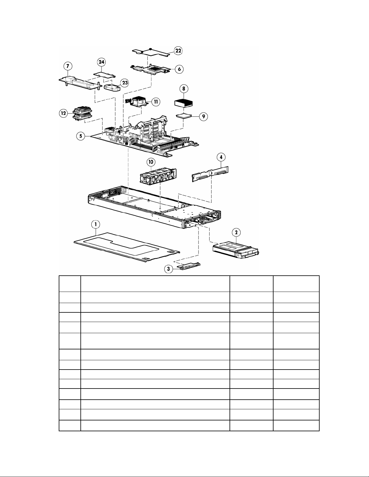
Server blade components
Item Description
1 Access panel 371709-001 Yes
2 Hard drive blank 122759-001 Yes
3
4 SCSI backplane with cables (cables not shown *) 371701-001 Yes
5 System board 381811-001 Yes
6 Standard NIC mezzanine card 381816-001 Yes
7 HP Smart Array 6i Controller 371702-001 Yes
8 Processor heatsink 381812-001 Yes
9 Processor
Mechanical components
Boards
Power button/LED board kit with LED cable (cable not
shown *)
System components
a) 2.4-GHz, single-core AMD Opteron™ Model 250 * 381836-001 Yes
Spare part
number
371706-001 Yes
Customer
replaceable?
Illustrated parts catalog 6
Page 7

Item Description
10 Fan assembly 371708-001 Yes
11 DC filter module 371705-001 Yes
12 Power converter modules (2) 371754-001 Yes
13 1p enabler board (processor blank not included) * 403929-001 Yes
14 Plastics kit* 381814-001 —
15 Replacement battery, 3.6-V NiMH * 307132-001 Yes
16 Server blade return kit * 237582-001 Yes
17 Local I/O cable * 355935-001 Yes
18 DIMM, 512 MB, PC-3200 DDR SDRAM *1 381817-001 Yes
19 DIMM, 1 GB, PC-3200 DDR SDRAM *1 381818-001 Yes
20 DIMM, 2 GB, PC-3200 DDR SDRAM *1 381819-001 Yes
21 DIMM, 4 GB, PC-3200 DDR SDRAM *1 395547-001 Yes
b) 2.6-GHz, single-core AMD Opteron™ Model 252 * 381837-001 Yes
c) 2.8-GHz, single-core AMD Opteron™ Model 254 * 404041-001 Yes
d) 1.8-GHz, dual-core AMD Opteron™ Model 265 * 391837-001 Yes
e) 2.0-GHz, dual-core AMD Opteron™ Model 270 * 391838-002 Yes
f) 2.2-GHz, dual-core AMD Opteron™ Model 275 * 391837-003 Yes
g) 2.4-GHz, dual-core AMD Opteron™ Model 280 * 404045-001 Yes
Miscellaneous
a) Air baffle — Yes
b) Bezel assembly — Yes
c) Ejector latch assembly — Yes
d) Quarter-turn standoffs (2) — Yes
e) Rear power connector thumbscrews (2) — Yes
Memory
Options
Spare part
number
Customer
replaceable?
22 FC mezzanine — —
23
24 HP Smart Array 6i Memory Module 351518-001 Yes
25 RJ-45 Patch Panel 1, with Fibre Channel support * 322299-001 Yes
26 Transceiver, 2-GB, Fibre Channel * 229204-001 Yes
*Not shown
1
DIMMs must be installed in identical pairs
a) Emulex-based Fibre Channel Mezzanine for HP p-Class
BladeSystem
b) QLogic-based Fibre Channel Mezzanine for HP p-Class
BladeSystem
HP Smart Array 6i 128-MB Battery-Backed Write Cache
Enabler Battery
399852-001 Yes
381813-001 Yes
307132-001 Yes
Illustrated parts catalog 7
Page 8

Removal and replacement procedures
In this section
Safety considerations................................................................................................................................ 8
Server blade preparation ........................................................................................................................ 11
Access panel ......................................................................................................................................... 12
Hard drives ........................................................................................................................................... 12
DIMMs.................................................................................................................................................. 13
Processor .............................................................................................................................................. 14
HP Smart Array 6i Controller................................................................................................................... 17
HP Smart Array 6i battery-backed write cache enabler (optional)................................................................. 18
Air baffle............................................................................................................................................... 18
Fan assembly......................................................................................................................................... 19
Fibre Channel mezzanine (optional)......................................................................................................... 20
Standard NIC mezzanine card ................................................................................................................ 21
SCSI backplane ..................................................................................................................................... 22
Power converter module.......................................................................................................................... 23
DC filter module..................................................................................................................................... 23
Power button/LED board......................................................................................................................... 24
System board battery.............................................................................................................................. 25
System board......................................................................................................................................... 26
Server blade bay blank........................................................................................................................... 28
Safety considerations
Preventing electrostatic discharge
Before performing service procedures, review all the safety information.
To prevent damaging the system, be aware of the precautions you need to follow when setting up the
system or handling parts. A discharge of static electricity from a finger or other conductor may damage
system boards or other static-sensitive devices. This type of damage may reduce the life expectancy of the
device.
To prevent electrostatic damage:
• Avoid hand contact by transporting and storing products in static-safe containers.
• Keep electrostatic-sensitive parts in their containers until they arrive at static-free workstations.
• Place parts on a grounded surface before removing them from their containers.
• Avoid touching pins, leads, or circuitry.
• Always be properly grounded when touching a static-sensitive component or assembly.
Removal and replacement procedures 8
Page 9

Server blade warnings and cautions
WARNING: To reduce the risk of injury from high-current electrical energy, do not
remove the server blade access panel when power is applied through the HP ProLiant
p-Class diagnostic station. Remove all power from the server blade before removing the
access panel.
WARNING: To reduce the risk of shock or injury from high-current electrical energy, do
not remove the server blade access panel while the server blade is installed in the server
blade enclosure. Do not remove the server blade access panel and then install the server
blade into the server blade enclosure.
WARNING: To reduce the risk of personal injury from hot surfaces, allow the drives and
the internal system components to cool before touching them.
CAUTION: When performing non-hot-plug operations, you must power down the server blade and/or the
system. However, it may be necessary to leave the server blade powered up when performing other
operations, such as hot-plug installations or troubleshooting.
Rack warnings and cautions
WARNING: To reduce the risk of personal injury or damage to the equipment, be sure
that:
• The leveling jacks are extended to the floor.
• The full weight of the rack rests on the leveling jacks.
• The stabilizing feet are attached to the rack if it is a single-rack installation.
• The racks are coupled together in multiple-rack installations.
• Only one component is extended at a time. A rack may become unstable if more than
one component is extended for any reason.
WARNING: To reduce the risk of personal injury or equipment damage when unloading
a rack:
• At least two people are needed to safely unload the rack from the pallet. An empty
42U rack can weigh as much as 115 kg (253 lb), can stand more than 2.1 m (7 ft)
tall, and may become unstable when being moved on its casters.
• Never stand in front of the rack when it is rolling down the ramp from the pallet.
Always handle the rack from both sides.
WARNING: When installing a server in a telco rack, be sure that the rack frame is
adequately secured to the top and bottom of the building structure.
WARNING: This server blade enclosure is very heavy. To reduce the risk of personal
injury or damage to the equipment:
• Observe local occupational health and safety requirements and guidelines for manual
material handling.
• Get help to lift and stabilize the product during installation or removal, especially
when the product is not fastened to the rails. When the server blade enclosure
weighs more than 22.5 kg (50 lb), at least two people must lift the server blade
enclosure into the rack together. A third person may be required to help align the
server blade enclosure if the server blade is installed higher than chest level.
• Use caution when installing the server blade enclosure in or removing the server
blade enclosure from the rack; it is unstable when not fastened to the rails.
Removal and replacement procedures 9
Page 10
WARNING: To reduce the risk of personal injury from hot surfaces, allow the drives and
the internal system components to cool before touching them.
CAUTION: Protect the server from power fluctuations and temporary interruptions with a regulating
uninterruptible power supply (UPS). This device protects the hardware from damage caused by power
surges and voltage spikes and keeps the system in operation during a power failure.
CAUTION: Do not operate the server blade for long periods with the access panel open or removed.
Operating the server blade in this manner results in improper airflow and improper cooling that can lead to
thermal damage.
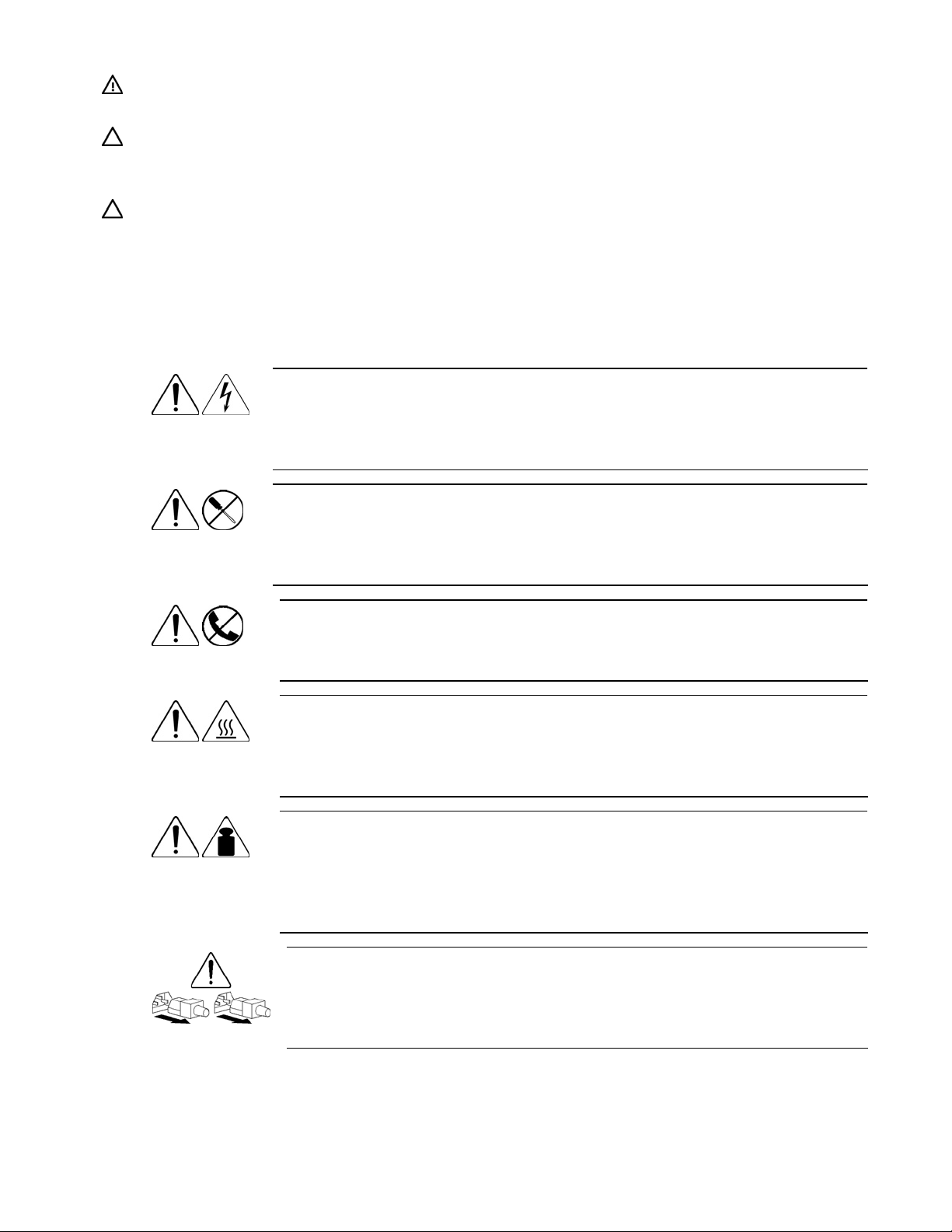
Symbols on equipment
The following symbols may be placed on equipment to indicate the presence of potentially hazardous
conditions.
This symbol indicates the presence of hazardous energy circuits or electric shock
9.43 kg
20.8 lb
hazards. Refer all servicing to qualified personnel.
WARNING: To reduce the risk of injury from electric shock hazards, do not open
this enclosure. Refer all maintenance, upgrades, and servicing to qualified personnel.
This symbol indicates the presence of electric shock hazards. The area contains no
user or field serviceable parts. Do not open for any reason.
WARNING: To reduce the risk of injury from electric shock hazards, do not open
this enclosure.
This symbol on an RJ-45 receptacle indicates a network interface connection.
WARNING: To reduce the risk of electric shock, fire, or damage to the equipment,
do not plug telephone or telecommunications connectors into this receptacle.
This symbol indicates the presence of a hot surface or hot component. If this surface is
contacted, the potential for injury exists.
WARNING: To reduce the risk of injury from a hot component, allow the surface to
cool before touching.
This symbol indicates that the component exceeds the recommended weight for one
individual to handle safely.
WARNING: To reduce the risk of personal injury or damage to the equipment,
observe local occupational health and safety requirements and guidelines for manual
material handling.
These symbols, on power supplies or systems, indicate that the equipment is supplied
by multiple sources of power.
WARNING: To reduce the risk of injury from electric shock, remove all power
cords to completely disconnect power from the system.
Removal and replacement procedures 10
Page 11
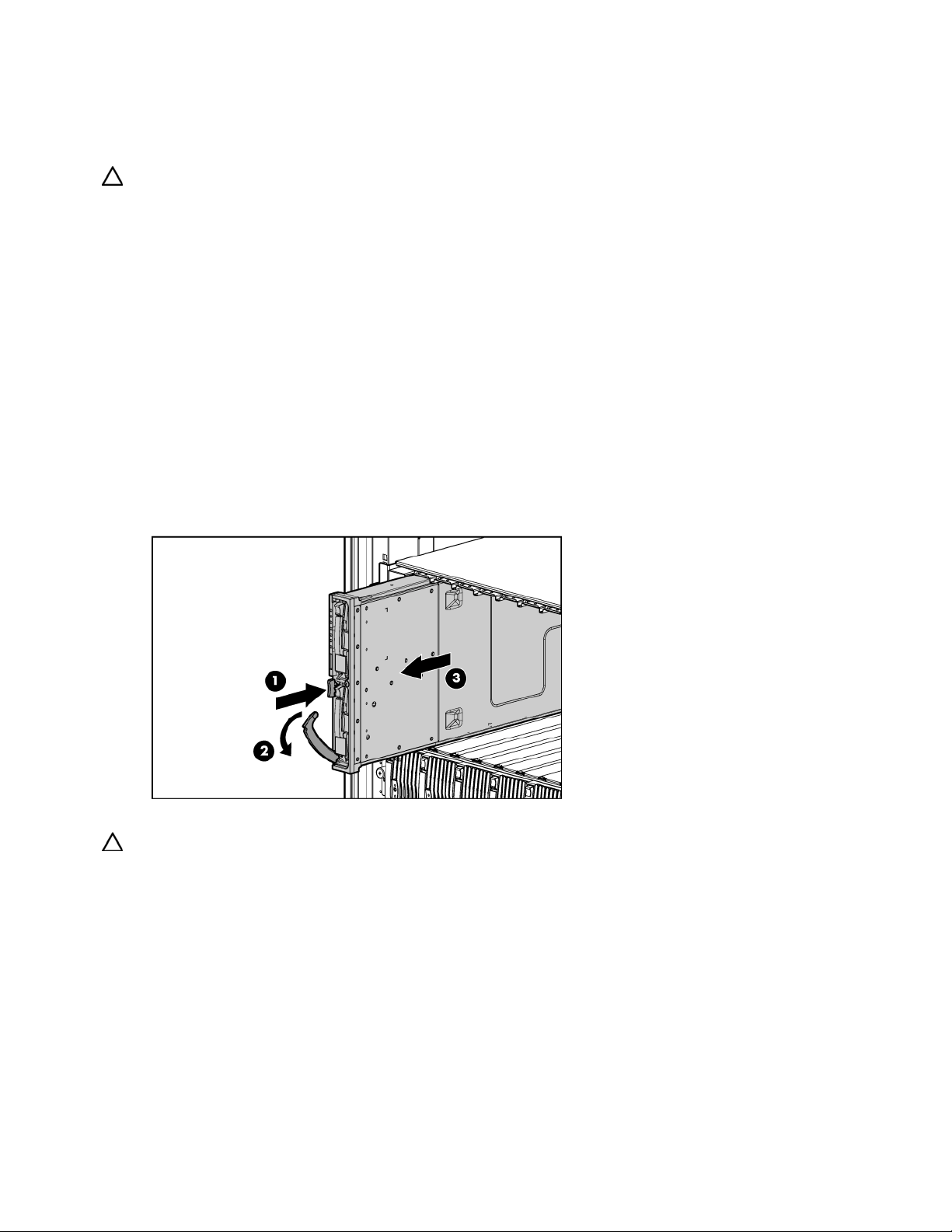
Server blade preparation
To service any internal server blade component, power down the server blade and remove it from the
server blade enclosure.
CAUTION: Electrostatic discharge (ESD) can damage electronic components. Be sure that you are properly
grounded (earthed) before beginning any installation procedure.
System power in server blades does not completely shut off with the front panel power switch or iLO
Virtual Power Button feature. The function toggles between on and standby modes, rather than on and off.
The standby position removes power from most electronics and the drives, but portions of the power
supply and some internal circuitry remain active.
To service internal server blade components:
1. Identify the proper server blade in the server blade enclosure.
2. Back up all server blade data.
3. Power down the server blade in one of the following ways:
• Use the Virtual Power Button feature in the iLO Remote Console to power down the server blade
from a remote location. Be sure that the server blade is in standby mode by observing that the
power LED is amber.
• Press the power button on the front of the server blade. Be sure that the server blade is in standby
mode by observing that the power LED is amber.
4. Remove the server blade from the server blade enclosure.
5. Place the server blade on a flat level surface.
CAUTION: Always populate server blade enclosure bays with either a server blade or server blade blank.
Operating the enclosure without a server blade or server blade blank results in improper airflow and
improper cooling that can lead to thermal damage.
To install and power up a server blade, reverse the removal procedure. Server blades are set to power up
automatically upon insertion. If you have changed this setting, use the power button or iLO Virtual Power
Button feature to power up the server blade.
For more information about iLO, refer to the HP Integrated Lights-Out User Guide.
Removal and replacement procedures 11
Page 12
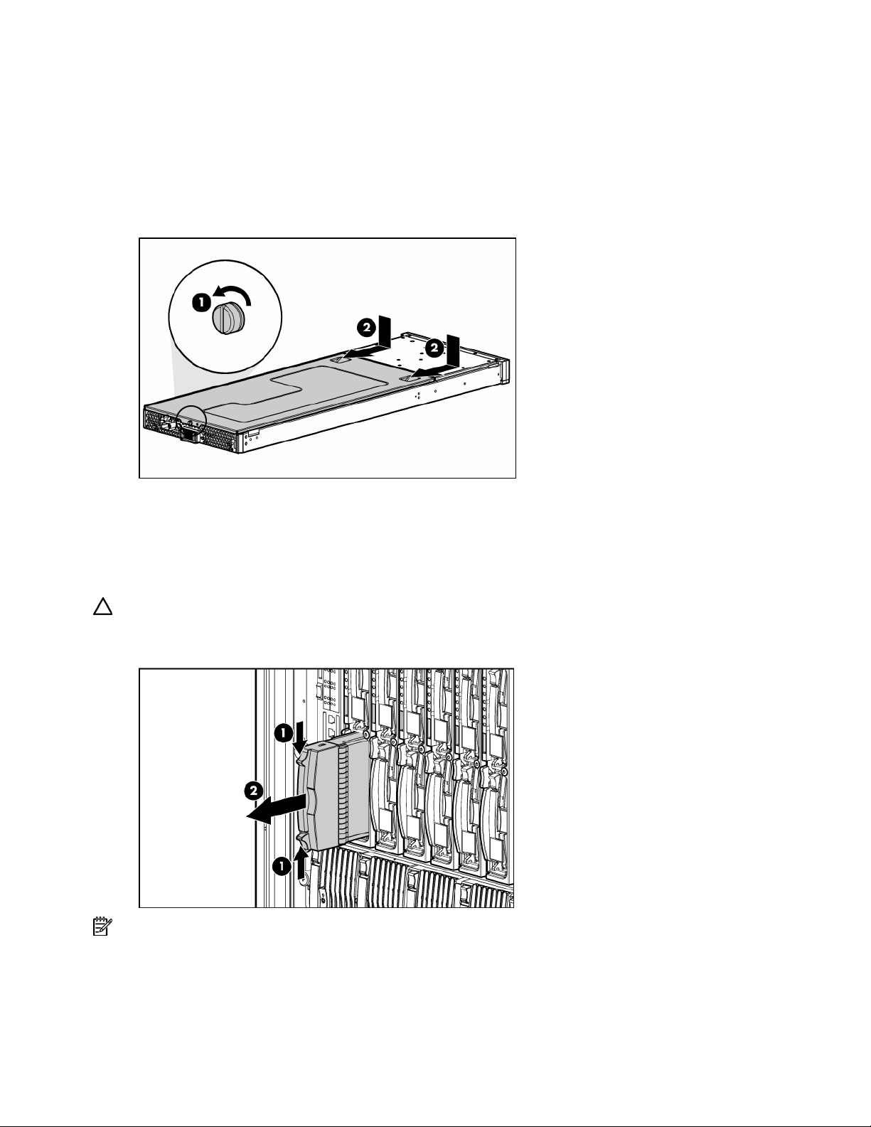
Access panel
To remove the component:
1. Power down the server blade and remove it from the server blade enclosure ("Server blade
preparation" on page 11).
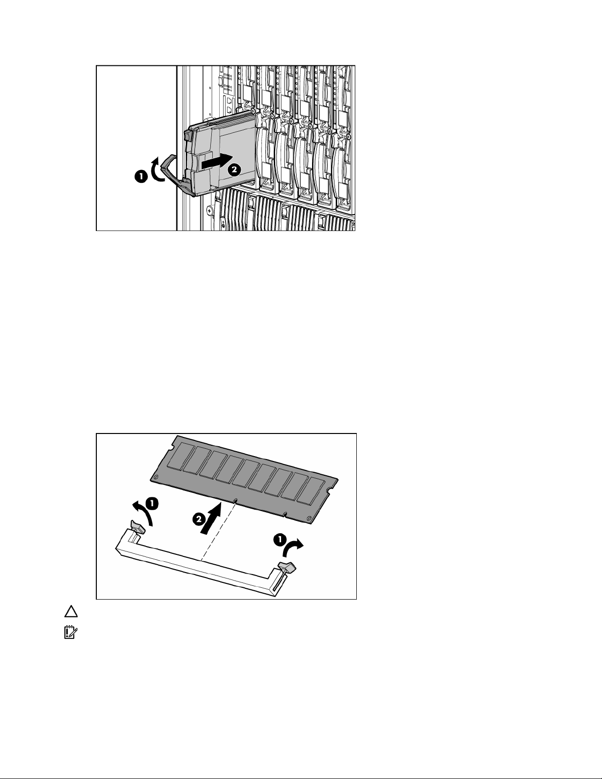
2. Loosen the thumbscrew.
3. Press down on the thumb indentations, slide the access panel toward the rear of the unit about 1.25
cm (0.5 in), and lift to remove the panel.
To replace the component, reverse the removal procedure.
Hard drives
To install the component:
CAUTION: To prevent improper cooling and thermal damage, do not operate the server unless all bays
are populated with either a component or a blank.
1. Remove the hard drive blank.
NOTE: Port-colored items indicate hot-plug components.
Removal and replacement procedures 12
Page 13
2.
Install the hard drive.
3. Determine the status of the hard drive from the hot-plug hard drive LEDs ("Hot-plug SCSI hard drive
LEDs" on page 37).
Resume normal server operations.
To remove the component, reverse the installation procedure.
DIMMs
To remove the component:
1. Power down the server blade and remove it from the server blade enclosure ("Server blade
2. Remove the access panel ("Access panel" on page 12).
3. Open the DIMM slot latches.
4. Remove the DIMM from the slot.
preparation" on page 11).
CAUTION: Use only HP DIMMs. DIMMs from other sources may adversely affect data integrity.
IMPORTANT: For DIMM slots 1 and 2, remove the air baffle, if necessary.
To replace the component, reverse the removal procedure.
Observe the following DIMM installation guidelines:
• All DIMMs must be PC3200 DDR 400-MHz SDRAM DIMMs.
Removal and replacement procedures 13
Page 14

•
Both DIMM slots in a memory bank must be populated.
• Both DIMMs in a memory bank must be identical.
• Processor 1 memory bank 1 must always be populated.
• If mixing dual- and single-rank DIMMs, the dual-rank DIMMs must be installed in memory bank 1.
For optimal performance in most applications, populate memory bank 1 for every populated processor
socket.
PC3200 DIMMs can either be single- or dual-rank. While it is not normally important for you to
differentiate between these two types of DIMMs, certain DIMM configuration requirements are based on
these classifications.
Certain configuration requirements exist with single- and dual-rank DIMMs that allow the architecture to
optimize performance. A dual-rank DIMM is similar to having two separate DIMMs on the same module.
Although only a single DIMM module, a dual-rank DIMM acts as if it were two separate DIMMs. The
primary reason for the existence of dual-rank DIMMs is to provide the largest capacity DIMM given the
current DIMM technology. If the maximum DIMM technology allows for creating 2-GB single-rank DIMMs,
a dual-rank DIMM using the same technology would be 4-GB.
Item Description Memory bank
1-2 DIMM slots 1 and 2 Processor 1 memory bank 1
3-4 DIMM slots 3 and 4 Processor 1 memory bank 2
5-6 DIMM slots 5 and 6 Processor 2 memory bank 1
7-8 DIMM slots 7 and 8 Processor 2 memory bank 2
Processor
To remove the component:
1. Power down the server blade and remove it from the server blade enclosure ("Server blade
preparation" on page 11).
2. Remove the access panel ("Access panel" on page 12).
Removal and replacement procedures 14
Page 15

3.
Open the processor cage latch.
4. Open the processor cage.
5. Remove the heatsink.
6. Open the processor locking lever.
7. Remove the processor.
CAUTION: The heatsink is not reusable and must be discarded if removed from the processor after
application.
CAUTION: Always install a processor or a processor blank and 1P enabler board in processor socket 2. If
processor socket 2 is empty, the server blade will not boot.
To install the component:
1. Install the processor.
CAUTION: Be sure that the processor socket locking lever is open before installing the processor into the
socket.
CAUTION: The processor is designed to fit one way into the socket. Use the alignment guides on the
processor and socket to properly align the processor with the socket. Refer to the server blade hood label for
specific instructions.
2. Close the processor locking lever.
CAUTION: Be sure that the processor socket locking lever is closed after the processor is installed. The
lever should close without resistance. Forcing the lever closed can damage the processor and socket,
requiring system board replacement.
Removal and replacement procedures 15
Page 16

3.
Remove the protective cover from the thermal interface.
CAUTION: After the cover is removed, do not touch the thermal interface media.
IMPORTANT: The heatsink is not reusable and must be discarded if removed from the processor after
application.
4. Insert the heatsink and close the processor cage. Closing the processor cage aligns the heatsink.
5. Close and secure the processor cage latch.
Removal and replacement procedures 16
Page 17

CAUTION: To avoid overheating of the dual core processor, the old air baffle must be replaced when
upgrading from a single core processor to a dual core processor.
IMPORTANT: To ensure proper cooling, be sure the correct processor air baffle (on page 18) is installed
at all times.
HP Smart Array 6i Controller
To remove the component:
1. Power down the server blade and remove it from the server blade enclosure ("Server blade
preparation" on page 11).
2. Remove the access panel ("Access panel" on page 12).
3. Turn the standoffs one quarter-turn.
4. Remove the controller from the server blade.
CAUTION: Disconnecting the battery module cable will cause any unsaved data in the memory module to
be lost.
To install the component:
1. Install the controller.
2. Turn the standoffs one quarter-turn.
Removal and replacement procedures 17
Page 18

HP Smart Array 6i battery-backed write cache enabler (optional)
To remove the component:
1. Power down the server blade and remove it from the server blade enclosure ("Server blade
preparation" on page 11).
2. Remove the access panel ("Access panel" on page 12).
CAUTION: Disconnecting the battery module cable will cause any unsaved data in the memory module to
be lost.
3. Remove the BBWCE from the controller.
4. Remove the battery from the BBWC memory module.
To replace the component, reverse the removal procedure.
Air baffle
To remove the component:
1. Power down the server blade and remove it from the server blade enclosure ("Server blade
preparation" on page 11).
2. Remove the access panel ("Access panel" on page 12).
Removal and replacement procedures 18
Page 19

3.
Remove the air baffle.
To replace the component, reverse the removal procedure.
CAUTION: To avoid overheating of the dual core processor, the old air baffle must be replaced when
upgrading from a single core processor to a dual core processor.
IMPORTANT: To ensure proper cooling, be sure the correct processor air baffle (on page 18) is installed
at all times.
Fan assembly
To remove the component:
1. Power down the server blade and remove it from the server blade enclosure ("Server blade
preparation" on page 11).
2. Remove the access panel ("Access panel" on page 12).
3. Remove the air baffle ("Air baffle" on page 18).
4. Disconnect the fan assembly cables from the system board.
IMPORTANT: Be sure to connect the cables to the same connectors when replacing the fan assembly.
Removal and replacement procedures 19
Page 20

5.
Press the fan retention tab and lift the assembly away from the system board.
To replace the component, reverse the removal procedure.
IMPORTANT: To ensure proper cooling, be sure the correct processor air baffle (on page 18) is installed
at all times.
Fibre Channel mezzanine (optional)
An optional FC mezzanine enables FC support (for clustering capabilities) and SAN connection when
used in conjunction with the RJ-45 Patch Panel 2 or the GbE2 Interconnect Switch with FC pass-through
option. The card is installed on top of the standard NIC mezzanine card.
To remove the component:
1. Power down the server blade and remove it from the server blade enclosure ("Server blade
preparation" on page 11).
2. Remove the access panel ("Access panel" on page 12).
3. Loosen the thumbscrews.
4. Lift the FC mezzanine away from the system board.
To replace the component, reverse the removal procedure.
Removal and replacement procedures 20
Page 21

IMPORTANT: Refer to the label on the FC mezzanine to verify compatibility with the server blade.
Standard NIC mezzanine card
To remove the component:
1. Power down the server blade and remove it from the server blade enclosure ("Server blade
preparation" on page 11).
2. Remove the access panel ("Access panel" on page 12).
3. Remove the FC mezzanine ("Fibre Channel mezzanine (optional)" on page 20).
4. Loosen the thumbscrews.
5. Lift the standard NIC mezzanine card away from the system board.
CAUTION: Be sure to lift the board straight up. Lifting one edge of the board at a time may damage the
connectors.
To replace the component, reverse the removal procedure.
Removal and replacement procedures 21
Page 22
SCSI backplane
To remove the component:
1. Power down the server blade and remove it from the server blade enclosure. ("Server blade
preparation" on page 11)
2. Remove the access panel ("Access panel" on page 12).
3. Remove any hot-plug SCSI hard drives or hard drive blanks ("Hard drives" on page 12).
4. Remove the fan assembly ("Fan assembly" on page 19).
5. Disconnect the SCSI backplane power cable from the system board.
6. Remove the plastic air baffle.
7. Disconnect the SCSI backplane signal cable from the system board.
CAUTION: Be sure the LED board cable is not disengaged when removing the air baffle. When reinstalling
the air baffle, be sure the cable is fully seated.
NOTE: The air baffle is most easily removed at a 45° angle.
8. Grasp the SCSI backplane on the left side when facing the rear of the server blade and lift slightly to
rotate the SCSI backplane out.
9. Lift the SCSI backplane out of the chassis.
To replace the component, reverse the removal procedure.
Removal and replacement procedures 22
Page 23

Power converter module
To remove the component:
1. Power down the server blade and remove it from the server blade enclosure ("Server blade
preparation" on page 11).
2. Remove the access panel ("Access panel" on page 12).
3. Loosen the thumbscrew and remove the power converter module.
4. Remove the power converter module retainers from the power converter module and store for use on
the new power converter module.
NOTE: The server requires two power converter modules installed one on top of the other. The power
converter modules may separate during removal or installation. Be sure to align the modules and press
together before installing on the system board.
To replace the component, reverse the removal procedure.
DC filter module
To remove the component:
1. Power down the server blade and remove it from the server blade enclosure ("Server blade
preparation" on page 11).
2. Remove the access panel ("Access panel" on page 12).
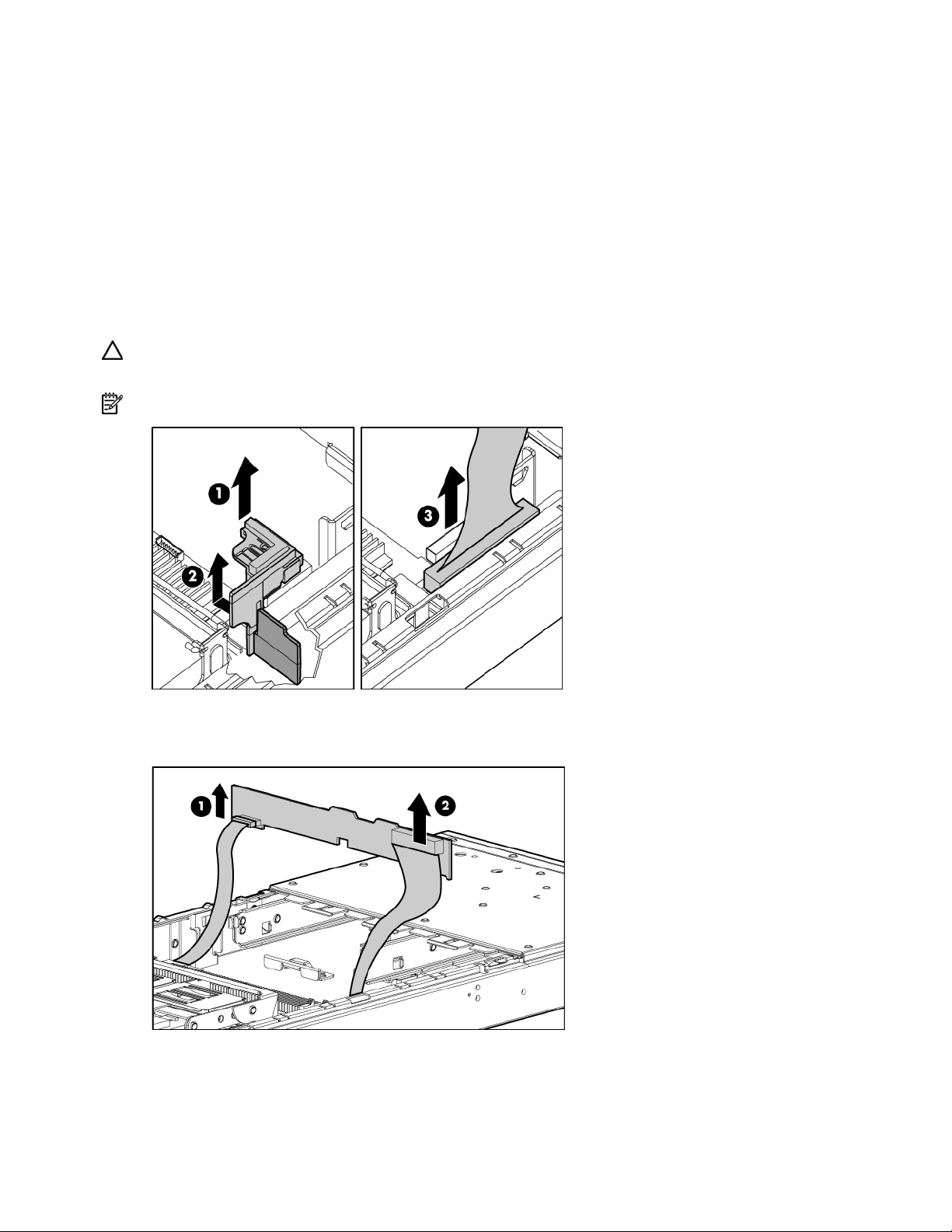
3. Remove the thumbscrews on the back of the chassis to release the power connector.
NOTE: The power connector will not push completely into the chassis until the DC filter module is removed.
It may be necessary to push in the power connector while removing the DC filter module.
Removal and replacement procedures 23
Page 24

4.
Release the latches and lift the DC filter module away from the system board while pushing the
power connector into the chassis.
To replace the component, reverse the removal procedure.
Power button/LED board
To remove the component:
1. Power down the server blade and remove it from the server blade enclosure ("Server blade
preparation" on page 11).
2. Remove the access panel ("Access panel" on page 12).
3. Remove any hot-plug SCSI hard drives or hard drive blanks ("Hard drives" on page 12).
4.
With a T-6 Torx screwdriver, remove the two retaining screws from the bottom of the chassis.
5. Disconnect the power button/LED cable from the rear left side of the power button/LED board.
6. Slide the power button/LED board toward the left outside edge of the chassis.
7. Tilt the front edge of the power button/LED board down until the keyholes on the rear of the board
clear the alignment pins.
Removal and replacement procedures 24
Page 25
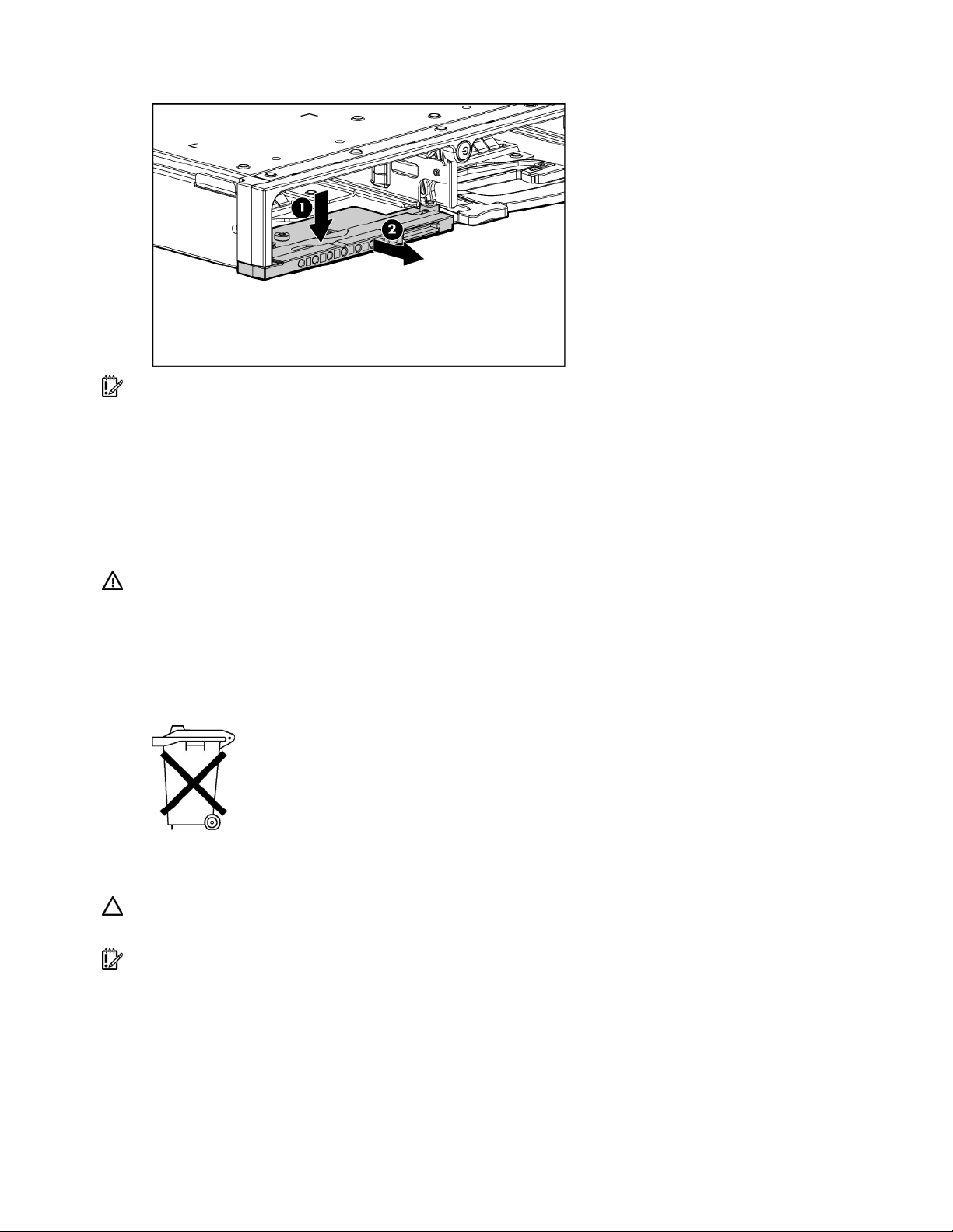
8.
Slide the power button/LED board out of the front of the chassis.
IMPORTANT: Be sure the tab at the end of the power button/LED cable is inserted under the power
button/LED board bezel.
To replace the component, reverse the removal procedure.
System board battery
If the server blade no longer automatically displays the correct date and time, you may need to replace
the battery that provides power to the real-time clock. Under normal use, battery life is 5 to 10 years.
WARNING: The computer contains an internal lithium manganese dioxide, a vanadium
pentoxide, or an alkaline battery pack. A risk of fire and burns exists if the battery pack
is not properly handled. To reduce the risk of personal injury:
• Do not attempt to recharge the battery.
• Do not expose the battery to temperatures higher than 60°C (140°F).
• Do not disassemble, crush, puncture, short external contacts, or dispose of in fire or
water.
Batteries, battery packs, and accumulators should not be disposed of together with the
general household waste. To forward them to recycling or proper disposal, please use
the public collection system or return them to HP, an authorized HP Partner, or their
agents.
For more information about battery replacement or proper disposal, contact an authorized reseller or an
authorized service provider.
CAUTION: Loss of BIOS settings occurs if the lithium battery is removed. BIOS settings must be
reconfigured whenever the battery is replaced.
IMPORTANT: After replacing the battery, the server blade is automatically configured with the default
settings. The user can update these settings using RBSU.
To remove the component:
1. Power down the server blade and remove it from the server blade enclosure ("Server blade
preparation" on page 11).
2. Remove the access panel ("Access panel" on page 12).
3. Locate the battery holder on the system board.
Removal and replacement procedures 25
Page 26
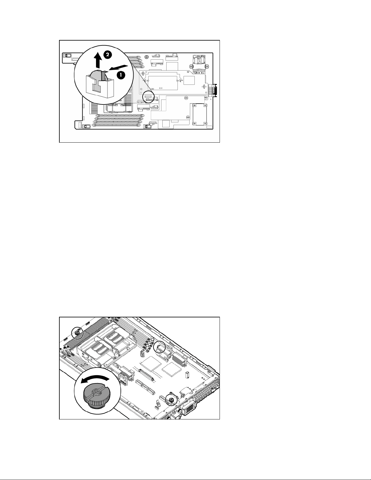
4.
Remove the existing battery by pushing the tab aside and pulling the battery straight up.
To install the system board battery, push it into the socket until the tab locks in place.
System board
To remove the component:
1. Power down the server blade and remove it from the server blade enclosure ("Server blade
preparation" on page 11).
2. Remove the access panel ("Access panel" on page 12).
3. Remove the DIMMs ("DIMMs" on page 13).
4. Remove the processor and heatsinks ("Processor" on page 14).
5. Remove the fan assembly ("Fan assembly" on page 19).
6. Remove the array controller ("HP Smart Array 6i Controller" on page 17).
7. Remove the FC mezzanine ("Fibre Channel mezzanine (optional)" on page 20).
8. Remove the standard NIC mezzanine card ("Standard NIC mezzanine card" on page 21).
9. Remove the SCSI backplane ("SCSI backplane" on page 22).
10. Remove the power converter module ("Power converter module" on page 23).
11. Remove the DC filter module ("DC filter module" on page 23).
12. Loosen the system board thumbscrews.
Removal and replacement procedures 26
Page 27

13.
Disconnect the LED cable from the system board before removing the system board from the server
blade.
14. Slide the system board toward the front of the server blade.
15. Lift the system board until it comes off the alignment keys.
16. Lift the edge of the system board nearest the system switches. The edge of the system board nearest
the array controller connectors tilts down into the chassis, and the edge of the system board nearest
the system switches tilts up out of the chassis.
17. Lift the system board out of the chassis.
To replace the component, reverse the removal procedure.
Removal and replacement procedures 27
Page 28

Server blade bay blank
Remove the server blade blank from the server blade enclosure.
CAUTION: To prevent improper cooling and thermal damage, do not operate the server blade enclosure
unless all bays are populated with either a component or a blank.
To replace a server blade blank, align the blank with the empty bay and slide it in until the blank is fully
seated.
Removal and replacement procedures 28
Page 29

Diagnostic tools
In this section
HP Insight Diagnostics............................................................................................................................. 29
Survey Utility.......................................................................................................................................... 29
Integrated Management Log.................................................................................................................... 29
HP Insight Diagnostics
HP Insight Diagnostics is a proactive server blade management tool, available in both offline and online
versions, that provides diagnostics and troubleshooting capabilities to assist IT administrators who verify
server blade installations, troubleshoot problems, and perform repair validation.
HP Insight Diagnostics Offline Edition performs various in-depth system and component testing while the
OS is not running. To run this utility, launch the SmartStart CD.
HP Insight Diagnostics Online Edition is a web-based application that captures system configuration and
other related data needed for effective server blade management. Available in Microsoft® Windows®
and Linux versions, the utility helps to ensure proper system operation.
For more information or to download the utility, refer to the HP website
(http://www.hp.com/servers/diags
).
Survey Utility
Survey Utility, a feature within HP Insight Diagnostics (on page 29), gathers critical hardware and
software information on ProLiant server blades.
This utility supports operating systems that may not be supported by the server blade. For operating
systems supported by the server blade, refer to the HP website (http://www.hp.com/go/supportos
If a significant change occurs between data-gathering intervals, the Survey Utility marks the previous
information and overwrites the Survey text files to reflect the latest changes in the configuration.
Survey Utility is installed with every SmartStart-assisted installation or can be installed through the HP PSP.
Integrated Management Log
The IML records hundreds of events and stores them in an easy-to-view form. The IML timestamps each
event with 1-minute granularity.
).
You can view recorded events in the IML in several ways, including the following:
• From within HP SIM
• From within Survey Utility (on page 29)
• From within operating system-specific IML viewers
• For NetWare: IML Viewer
• For Windows®: IML Viewer
Diagnostic tools 29
Page 30

•
For Linux: IML Viewer Application
• From within the iLO user interface
• From within HP Insight Diagnostics (on page 29)
For more information, refer to the Management CD in the HP ProLiant Essentials Foundation Pack.
Diagnostic tools 30
Page 31
Server component identification
In this section
Front panel components .......................................................................................................................... 31
Front panel LEDs .................................................................................................................................... 32
Rear panel components........................................................................................................................... 33
Internal components................................................................................................................................ 34
System maintenance switch ..................................................................................................................... 35
System maintenance switch procedures..................................................................................................... 35
Local I/O cable ..................................................................................................................................... 36
Hot-plug SCSI hard drive LEDs ................................................................................................................. 37
Hot-plug SCSI hard drive LED combinations............................................................................................... 37
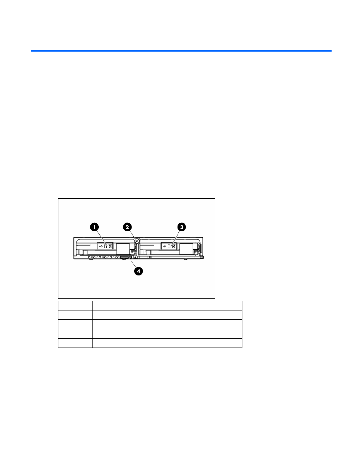
Front panel components
Item Description
1 Hot-plug SCSI hard drive bay 1
2 Power On/Standby button
3 Hot-plug SCSI hard drive bay 2
4 I/O port*
* The I/O port is used with the local I/O cable to perform some server blade configuration and diagnostic
procedures.
Server component identification 31
Page 32

Front panel LEDs
Item Description Status
1 UID LED Blue = Identified
Blue flashing = Active remote management
Off = No active remote management
2 Health LED Green = Normal
Flashing = Booting
Amber = Degraded condition
Red = Critical condition
3 NIC 1 LED* Green = Network linked
Green flashing = Network activity
Off = No link or activity
4 NIC 2 LED* Green = Network linked
Green flashing = Network activity
Off = No link or activity
5 NIC 3 LED* Green = Network linked
Green flashing = Network activity
Off = No link or activity
6 NIC 4 LED* Green = Network linked
Green flashing = Network activity
Off = No link or activity
7 Power On/Standby LED Green = On
Amber = Standby (auxiliary power available)
Off = Off
8 Hard drive activity LED Green/Flashing = Activity
Off = No activity
9 Online status Flashing = Online activity
Off = No online activity
Server component identification 32
Page 33
Item Description Status
10 Fault status Flashing = Fault process activity
* Actual NIC numeration depends on several factors, including the operating system installed on the server blade.
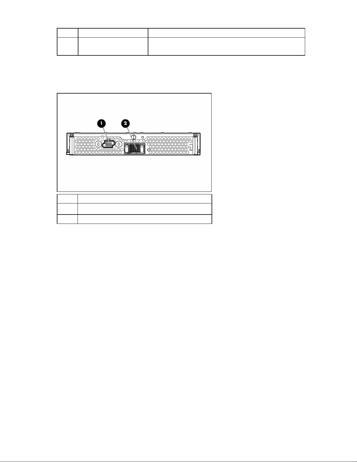
Rear panel components
Off = No fault process activity
Item Description
1 Power connector
2 Signal connector
Server component identification 33
Page 34

Internal components
Item Description
1 System maintenance switch (SW1)
2 DC filter module
3 Standard NIC mezzanine card
4 System battery
5 Processor 2 memory bank 2
6 Processor 2 memory bank 1 (shown populated)
7 DIMMs 5-8
8 Processor socket 2 (shown populated)
9 SCSI backplane board connector 2
10 Fan connectors
11 Power button/LED board connector
12 SCSI backplane board connector 1
13 Processor socket 1 (shown populated)
14 DIMMs 1-4
15 Processor 1 memory bank 1(shown populated)
16 Processor 1 memory bank 2
17
HP Smart Array 6i Battery-Backed Write Cache Enabler
(optional)
Server component identification 34
Page 35

Item Description
18 HP Smart Array 6i Controller
19 Power converter modules
20 FC mezzanine (optional)
System maintenance switch
Position Function Default
1* iLO Security override Off
2 Configuration lock Off
3 Reserved Off
4 Reserved Off
5* Password disabled Off
6* Reset configuration Off
7 Reserved Off
8 Reserved Off
*To access redundant ROM, set S1, S5, and S6 to ON.
System maintenance switch procedures
When you perform troubleshooting steps, this guide may instruct you to perform the following procedures:
• Clear the system configuration ("Clearing the system configuration" on page 35).
• Access the redundant ROM ("Accessing the redundant ROM" on page 36).
To complete these procedures, you must change physical settings on the system maintenance switch
Clearing the system configuration
(SW1).
To clear the system configuration:
1. Power down the server blade and disconnect the server blade from all power sources ("Server blade
preparation" on page 11).
2. Remove the access panel ("Access panel" on page 12).
3. Change position 6 of SW1 to on.
4. Install the access panel.
5. Connect the server blade to system power and power up the server blade ("Server blade
preparation" on page 11).
6. Wait for the POST message that prompts you to change the switch setting:
Maintenance switch detected in the "On" position.
Power off the server and turn switch to the "Off" position.
7. Repeat steps 1 through 3.
8. Change position 6 of SW1 to off.
9. Repeat steps 5 through 7.
Server component identification 35
Page 36
IMPORTANT: When the server blade boots after NVRAM is cleared, a delay of up to 2 minutes is normal.
During this delay, the system appears non-functional. Do not attempt any procedures during the delay.
Accessing the redundant ROM
If the system ROM is corrupted, you can set the system to use the backup version or redundant ROM.
To use the redundant ROM:
1. Power down the server blade and disconnect the server blade from all power sources ("Server blade
preparation" on page 11).
2. Remove the access panel ("Access panel" on page 12).
3. Change positions 1, 5, and 6 of SW1 to on.
4. Install the access panel ("Access panel" on page 12).
5. Connect the server blade to system power and power up the server blade ("Server blade
preparation" on page 11).
6. Repeat steps 1 through 3.
7. Change positions 1, 5, and 6 of SW1 to off.
8. Repeat steps 5 through 7.
If both the current and backup versions of the ROM are corrupt, you must return the system board for a
service replacement.
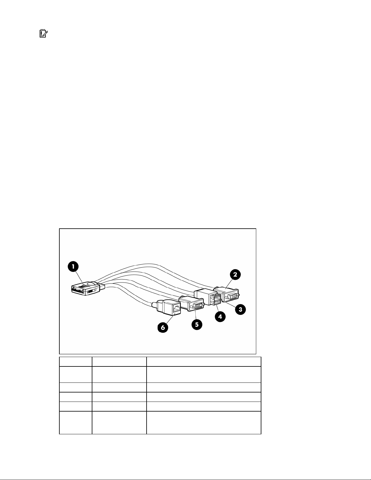
Local I/O cable
Item Connector Description
1 Local I/O
2 Video For connecting a video monitor
3 USB 1 For connecting a USB device
4 USB 2 For connecting a USB device
5 Serial
For connecting to the local I/O port on the
server blade front panel
For trained personnel to connect a null modem
serial cable and perform advanced diagnostic
procedures
Server component identification 36
Page 37
Item Connector Description
6
iLO RJ-45
(10/100 Ethernet)
For connecting an Ethernet to the server blade
iLO interface from a client device
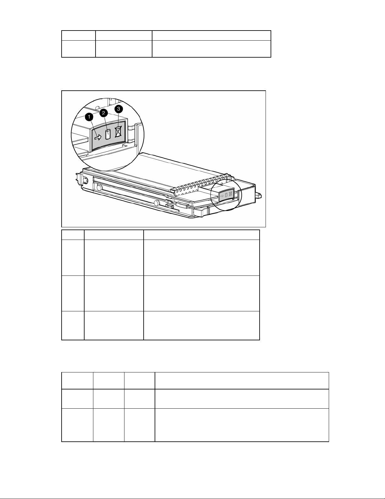
Hot-plug SCSI hard drive LEDs
Item LED description Status
1 Activity status On = Drive activity
Flashing = High activity on the drive or drive
is being configured as part of an array.
Off = No drive activity
2 Online status
On = Drive is part of an array and is
currently working.
Flashing = Drive is actively online.
Off = Drive is offline.
3 Fault status On = Drive failure
Flashing = Fault-process activity
Off = No fault-process activity
Hot-plug SCSI hard drive LED combinations
Activity
LED (1)
On, off, or
flashing
On, off, or
flashing
Online LED
(2)
Fault LED
(3)
Interpretation
On or off Flashing A predictive failure alert has been received for this drive.
Replace the drive as soon as possible.
On Off The drive is online and is configured as part of an array.
If the array is configured for fault tolerance and all other drives in the
array are online, and a predictive failure alert is received or a drive
capacity upgrade is in progress, you may replace the drive online.
Server component identification 37
Page 38

Activity
LED (1)
On or
flashing
Online LED
(2)
Fault LED
(3)
Flashing Off
Interpretation
Do not remove the drive. Removing a drive may
terminate the current operation and cause data loss.
The drive is rebuilding or undergoing capacity expansion.
On Off Off Do not remove the drive.
The drive is being accessed, but (1) it is not configured as part of an
array; (2) it is a replacement drive and rebuild has not yet started; or
(3) it is spinning up during the POST sequence.
Flashing Flashing Flashing
Do not remove the drive. Removing a drive may cause
data loss in non-fault-tolerant configurations.
One or more of the following conditions may exist:
• The drive is part of an array being selected by an array
configuration utility
• Drive Identification has been selected in HP SIM
• The drive firmware is being updated
Off Off On
The drive has been placed offline due to hard disk drive failure or
subsystem communication failure.
You may need to replace the drive.
Off Off Off One or more of the following conditions may exist:
• The drive is not configured as part of an array
• The drive is configured as part of an array, but it is a
replacement drive that is not being accessed or being rebuilt yet
• The drive is configured as an online spare
If the drive is connected to an array controller, you may replace the
drive online.
Server component identification 38
Page 39

Specifications
In this section
Environmental specifications.................................................................................................................... 39
Server specifications............................................................................................................................... 39
Environmental specifications
Specification Value
Temperature range*
Operating 10°C to 35°C (50°F to 95°F)
Shipping -40°C to 60°C (-40°F to 140°F)
Storage -20°C to 60°C (-4 to 140°C)
Maximum wet bulb temperature 30°C (86°F)
Relative humidity
(noncondensing)**
Operating 10% to 90%
Shipping 10% to 90%
Storage 10% to 95%
* All temperature ratings shown are for sea level. An altitude derating of 1°C per 304.8 m (1.8°F per 1,000 ft) to
3048 m (10,000 ft) is applicable. No direct sunlight allowed. Upper operating limit is 3,048m (10,000 ft) or 70
Kpa/10.1 psia. Upper non-operating limit is 9,144 m (30,000 ft) or 30.3 KPa/4.4 psia.
** Storage maximum humidity of 95% is based on a maximum temperature of 45°C (113°F). Altitude maximum for
storage corresponds to a pressure minimum of 70 KPa.
Server specifications
Specification Value
Height 4.29 cm (1.69 in)
Depth 71.1 cm (28.00 in)
Width 26.14 cm (10.29 in)
Weight (maximum) 9.43 kg (20.8 lb)
Specifications 39
Page 40

Acronyms and abbreviations
BBWC
battery-backed write cache
BIOS
Basic Input/Output System
DDR
double data rate
ESD
electrostatic discharge
FC
Fibre Channel
I/O
input/output
iLO
Integrated Lights-Out
IML
Integrated Management Log
IP
Internet Protocol
LED
light-emitting diode
NIC
network interface controller
POST
Power-On Self Test
Acronyms and abbreviations 40
Page 41

PSP
ProLiant Support Pack
RBSU
ROM-Based Setup Utility
RILOE
Remote Insight Lights-Out Edition
ROM
read-only memory
SA
Smart Array
SCSI
small computer system interface
SIM
Systems Insight Manager
UID
unit identification
UPS
uninterruptible power system
USB
universal serial bus
Acronyms and abbreviations 41
Page 42

Index
A
access panel 12
air baffle 18, 19, 22
array controllers 34
B
batteries, care and storage 25
battery-backed write cache 34
battery-backed write cache battery pack 34
battery-backed write cache enabler 17, 18, 34
buttons 31
C
cable connector identification 36
cables 36
cabling 36
cautions 9
component identification 31, 32, 33, 35
components 31
connectors 31, 36
CSR (customer self repair) 5
customer self repair 5
fan connectors 34
fan LED 37
fan zones 37
FC mezzanine 20, 34
features 31
Fibre Channel mezzanine 20, 34
front panel components 31, 32
front panel LEDs 32
H
hard drive LEDs 12, 37
hard drives 37
hard drives, determining status of 12, 37
hard drives, installing 12
health driver 37
health LEDs 37
heatsink 14
HP Insight Diagnostics 29
I
illustrated parts catalog 5
iLO connector 36
IML (Integrated Management Log) 29
Insight Diagnostics 29
D
DC filter module 23, 34
diagnostic tools 29
diagnostics utility 29
DIMM installation guidelines 13
DIMM slot LEDs 37
DIMM slot locations 13
DIMMs 13, 34
disposal, battery 25
drive LEDs 37
E
electrostatic discharge 8
environmental specifications 39
F
fan assembly 19
L
LED, power button 24, 31, 32
LEDs 31, 32, 37
LEDs, hard drive 32, 37
LEDs, unit identification 32
local I/O cable 36
M
management tools 29
N
NIC (network interface controller) 34, 40
O
overtemperature LED 37
Index 42
Page 43

P
power button 31, 34
power button/LED board 24
power converter module 23, 34
PPM failure LEDs 37
preparation procedures 11
processors 14, 34
R
rack warnings 9
redundant ROM 36
removal and replacement procedures 8
S
safety considerations 8
SCSI backplane 22
serial port 36
server blade bay blank 28
server, rear panel components 33
Smart Array 6i Controller 17
specifications 39
specifications, server 39
Standby mode 11
static electricity 8
Survey Utility 29
symbols on equipment 10
system battery 25, 34
system board battery 25
system maintenance switch 34, 35
T
temperature, overtemperature LED 37
thermal interface 14
tools 29
U
updating the system ROM 35
USB connectors 36
utilities 29
V
video connector 36
Virtual Power button 11
W
warnings 9
Index 43
 Loading...