

HP Apollo 6500 Gen10, ProLiant XL270d Gen10 User Manual

HPE Apollo 6500 Gen10 / HPE ProLiant XL270d Gen10 Server User Guide
Abstract
This document is for the person who installs, administers, and troubleshoots servers and storage
systems. Hewlett Packard Enterprise assumes you are qualified in the servicing of computer
equipment and trained in recognizing hazards in products with hazardous energy levels.
Part Number: P05100-002
Published: June 2018
Edition: 2

©
Copyright 2018 Hewlett Packard Enterprise Development LP
Notices
The information contained herein is subject to change without notice. The only warranties for Hewlett Packard
Enterprise products and services are set forth in the express warranty statements accompanying such
products and services. Nothing herein should be construed as constituting an additional warranty. Hewlett
Packard Enterprise shall not be liable for technical or editorial errors or omissions contained herein.
Confidential computer software. Valid license from Hewlett Packard Enterprise required for possession, use,
or copying. Consistent with FAR 12.211 and 12.212, Commercial Computer Software, Computer Software
Documentation, and Technical Data for Commercial Items are licensed to the U.S. Government under
vendor's standard commercial license.
Links to third-party websites take you outside the Hewlett Packard Enterprise website. Hewlett Packard
Enterprise has no control over and is not responsible for information outside the Hewlett Packard Enterprise
website.
Acknowledgments
Microsoft® and Windows® are either registered trademarks or trademarks of Microsoft Corporation in the
United States and/or other countries.

Contents
Component identification........................................................................... 6
Front panel components......................................................................................................................6
Front panel LEDs and buttons.............................................................................................................6
UID button functionality.............................................................................................................7
Front panel LED power fault codes.......................................................................................... 7
Rear panel components (SXM2 GPU module)....................................................................................8
Rear panel components (PCIe GPU module)..................................................................................... 9
System board components................................................................................................................10
System maintenance switch descriptions............................................................................... 11
NMI functionality..................................................................................................................... 11
DIMM slot locations................................................................................................................ 12
DIMM label identification.........................................................................................................12
SXM2 GPU module components.......................................................................................................14
PCIe GPU module components........................................................................................................ 14
Power distribution board and bus bar components........................................................................... 15
Power supply LED.............................................................................................................................15
Fan module numbering......................................................................................................................16
Supported drives............................................................................................................................... 16
Hot-plug drive LED definitions...........................................................................................................17
NVMe SSD LED definitions...............................................................................................................18
Operations..................................................................................................20
Power up the server.......................................................................................................................... 20
Power down the server......................................................................................................................20
Extending the chassis from the rack..................................................................................................20
Removing the GPU module from the chassis....................................................................................21
Removing the system board module from the chassis......................................................................22
Removing the access panel.............................................................................................................. 23
Removing the fan cage......................................................................................................................23
Removing the riser cage....................................................................................................................24
Setup...........................................................................................................26
Safety and regulatory compliance..................................................................................................... 26
Optional service.................................................................................................................................26
Warnings and cautions......................................................................................................................26
Determining power and cooling configurations..................................................................................28
Power requirements................................................................................................................28
HPE Modular Cooling System 300 and Apollo IT and CDU Rack system..............................28
HPE Apollo System Manager................................................................................................. 28
Hot-plug power supply calculations........................................................................................ 29
Connecting a DC power cable to a DC power source............................................................ 29
Optimum environment....................................................................................................................... 30
Space and airflow requirements............................................................................................. 30
Temperature requirements......................................................................................................31
Electrical grounding requirements.......................................................................................... 31
Identifying the contents of the shipping carton.................................................................................. 31
Installation overview.......................................................................................................................... 32
Installing the chassis into the rack.....................................................................................................32
Contents 3

Installing the rails and the cable management arm................................................................ 33
Installing hardware options ...............................................................................................................39
Operating system.............................................................................................................................. 39
Installing the operating system with Intelligent Provisioning...................................................39
Selecting boot options in UEFI Boot Mode........................................................................................39
Selecting boot options....................................................................................................................... 40
Registering the server....................................................................................................................... 40
Hardware options installation.................................................................. 41
Hewlett Packard Enterprise product QuickSpecs..............................................................................41
Introduction........................................................................................................................................41
Installing a power supply................................................................................................................... 41
Installing an 8SFF drive cage............................................................................................................42
Installing a hot-plug SAS or SATA drive............................................................................................ 44
Installing the NVMe enablement kit...................................................................................................45
Installing NVMe drives.......................................................................................................................47
Installing the M.2 SSD enablement option........................................................................................ 48
Installing a DIMM...............................................................................................................................50
Installing a type -a controller..............................................................................................................51
Installing a type -p controller..............................................................................................................52
Installing a full-length PCIe GPU.......................................................................................................53
Configuring PCIe GPU slots................................................................................................... 55
Installing an SXM2 GPU....................................................................................................................56
Installing a PCIe riser board in the SXM2 GPU module.................................................................... 59
Installing a PCIe riser board in the PCIe GPU module......................................................................60
Installing a processor heatsink assembly..........................................................................................61
Installing the HPE Smart Storage Battery......................................................................................... 64
Cabling........................................................................................................66
SAS/SATA cabling............................................................................................................................. 66
NVMe cabling.................................................................................................................................... 67
AC power cabling.............................................................................................................................. 68
Drive power cabling...........................................................................................................................69
Front LED/power/UID cabling............................................................................................................70
GPU module power cabling...............................................................................................................70
HPE Smart Storage Battery cabling.................................................................................................. 70
Software and configuration utilities.........................................................72
Server mode......................................................................................................................................72
Product QuickSpecs..........................................................................................................................72
Active Health System Viewer............................................................................................................ 72
Active Health System..............................................................................................................72
HPE iLO 5..........................................................................................................................................73
iLO Federation........................................................................................................................74
iLO Service Port......................................................................................................................74
iLO RESTful API.....................................................................................................................75
RESTful Interface Tool............................................................................................................75
iLO Amplifier Pack.................................................................................................................. 75
Intelligent Provisioning.......................................................................................................................75
Intelligent Provisioning operation............................................................................................76
Management Security........................................................................................................................76
Scripting Toolkit for Windows and Linux............................................................................................77
UEFI System Utilities.........................................................................................................................77
4 Contents

Selecting the boot mode ........................................................................................................77
Secure Boot............................................................................................................................78
Launching the Embedded UEFI Shell ....................................................................................79
HPE Smart Storage Administrator.....................................................................................................79
USB support...................................................................................................................................... 80
External USB functionality...................................................................................................... 80
Redundant ROM support...................................................................................................................80
Safety and security benefits....................................................................................................80
Keeping the system current...............................................................................................................80
Updating firmware or system ROM.........................................................................................80
Drivers.................................................................................................................................... 83
Software and firmware............................................................................................................83
Operating system version support.......................................................................................... 84
HPE Pointnext Portfolio.......................................................................................................... 84
Proactive notifications.............................................................................................................84
Troubleshooting.........................................................................................85
Troubleshooting resources................................................................................................................85
Removing and replacing the system battery.......................................... 86
Specifications............................................................................................ 87
Chassis mechanical specifications....................................................................................................87
Power supply specifications.............................................................................................................. 87
Electrostatic discharge............................................................................. 88
Preventing electrostatic discharge.....................................................................................................88
Grounding methods to prevent electrostatic discharge..................................................................... 88
Websites..................................................................................................... 89
Support and other resources................................................................... 90
Accessing Hewlett Packard Enterprise Support................................................................................ 90
Accessing updates............................................................................................................................ 90
Customer self repair.......................................................................................................................... 91
Remote support.................................................................................................................................91
Warranty information......................................................................................................................... 91
Regulatory information...................................................................................................................... 92
Documentation feedback...................................................................................................................92
Contents 5
Component identification
This chapter describes the external and internal server features and components.
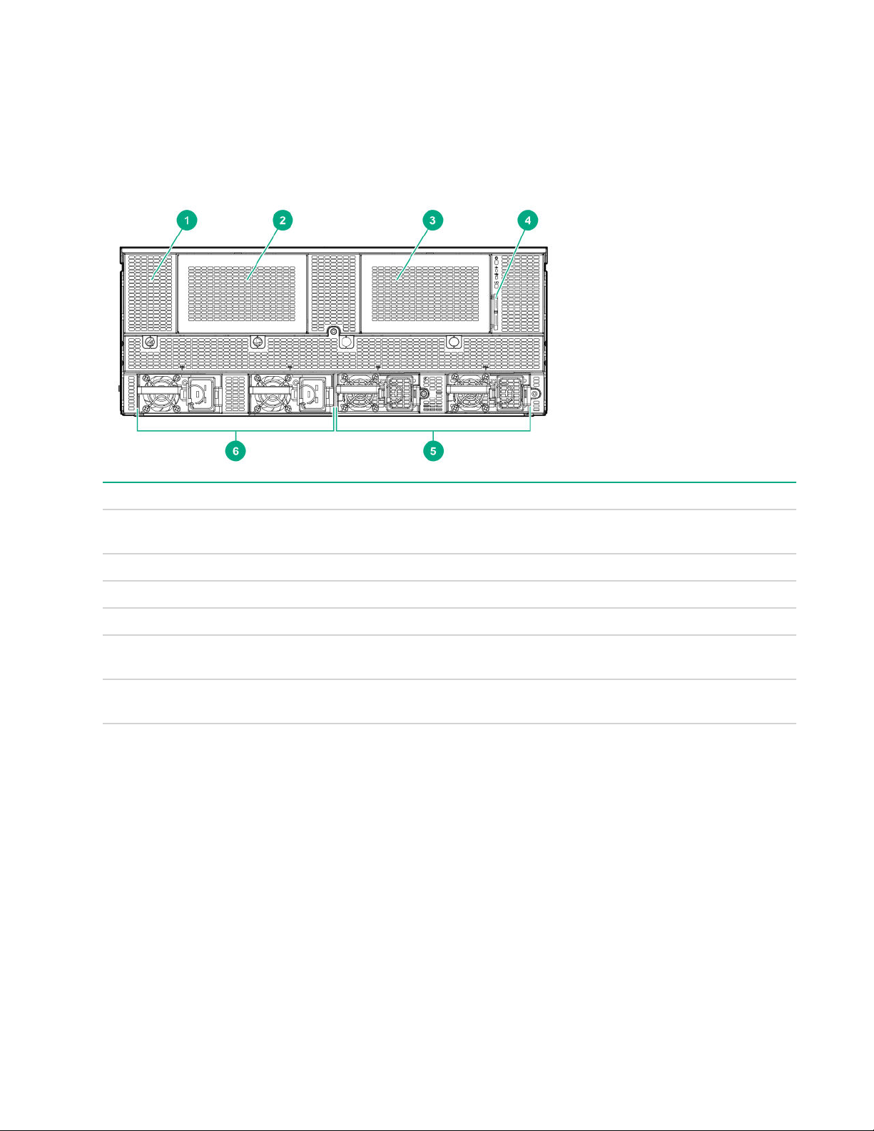
Front panel components
Item Description
1 HPE Smart Storage battery (located behind the
2 Drive bay 1 (for optional 8SFF drive cage)
3 Drive bay 2 (for optional 8SFF drive cage)
4 Serial label pull tab
5 Power supply bays 3 and 4 (for optional HPE 2200 W
6 HPE 2200W Platinum Hot Plug Power Supplies 1
Front panel LEDs and buttons
chassis grill)
Platinum Hot Plug Power Supplies)
and 2 (standard)
6 Component identification
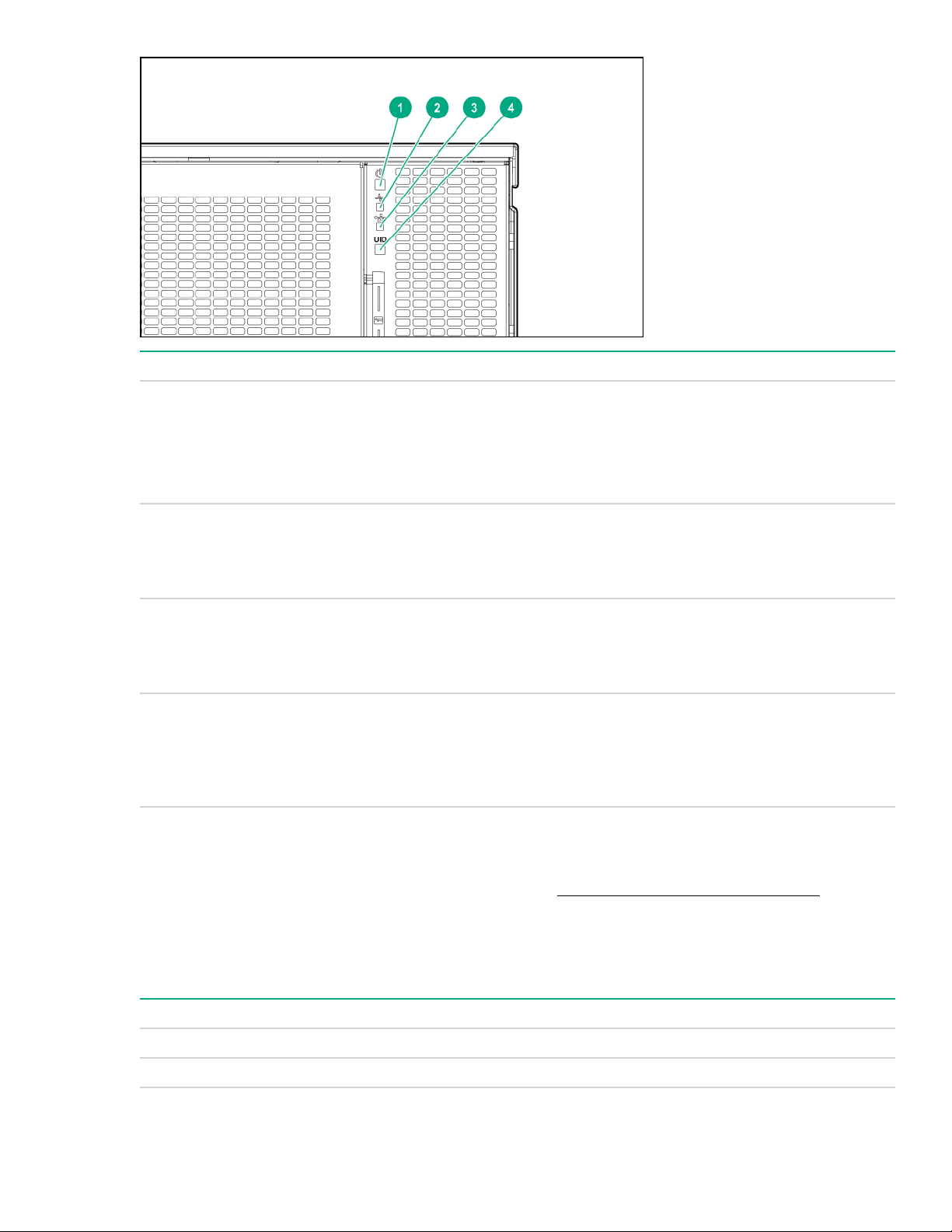
Item Description Status
1 Power on/Standby button and system
power LED
2 Health LED
3 NIC status LED
4 UID button LED
UID button functionality
Solid green = System on
Flashing green = Performing power on sequence
Solid amber = System in standby
Off = No power present
Solid green = Normal
Flashing amber= System degraded
Flashing red = System critical
Solid green = Link to network
Flashing green = Network active
Flashing red = System critical
Solid blue = Activated
Flashing blue = Remote management or firmware
upgrade in progress
Off = Deactivated
The UID button can be used to display the Server Health Summary when the server will not power on. For
more information, see the latest HPE iLO User Guide on the Hewlett Packard Enterprise website.
Front panel LED power fault codes
The following table provides a list of power fault codes, and the subsystems that are affected. Not all power
faults are used by all servers.
Subsystem LED behavior
System board 1 flash
Processor 2 flashes
Table Continued
UID button functionality 7
Subsystem LED behavior
Memory 3 flashes
Riser board PCIe slots 4 flashes
FlexibleLOM 5 flashes
Removable HPE Smart Array SR Gen10 controller 6 flashes
System board PCIe slots 7 flashes
Power backplane or storage backplane 8 flashes
Power supply 9 flashes
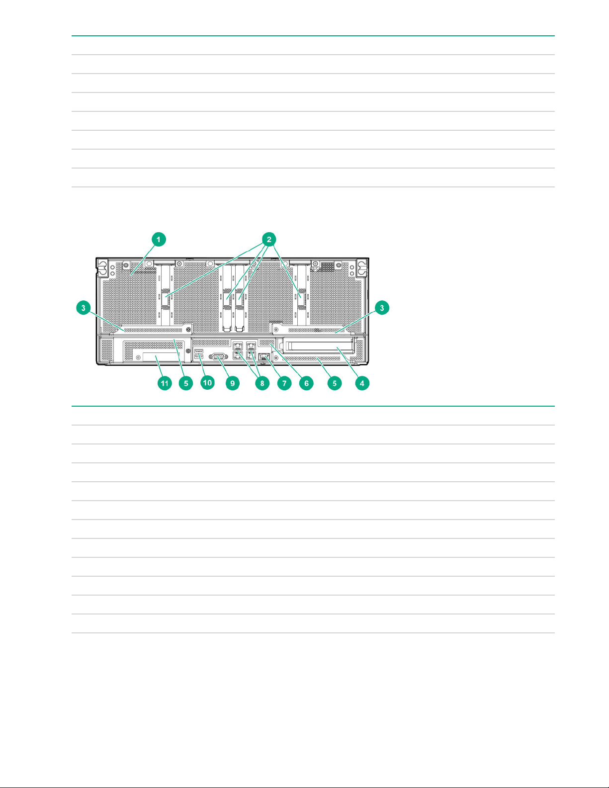
Rear panel components (SXM2 GPU module)
Item Description
1 GPU module
2 PCIe slots 9-12
3 GPU module latches
4 Full Height Half Length PCIe Gen3 slot (system board module)
5 System board module latches
6 System board module
7 Dedicated iLO management port
8 Embedded 4 x 1GbE Network Adapter
9 Video connector
10 USB 3.0 ports
11 FlexibleLOM slot
8 Rear panel components (SXM2 GPU module)
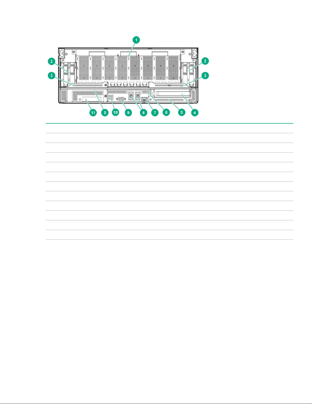
Rear panel components (PCIe GPU module)
Item Description
1 GPU module
2 Low-profile PCIe Gen3 slots 9-12 (GPU module)
3 GPU module latches
4 Full Height Half Length PCIe Gen3 slot (system board module)
5 System board module latches
6 System board module
7 Dedicated iLO management port
8 Embedded 4 x 1GbE Network Adapter
9 Video connector
10 USB 3.0 ports
11 FlexibleLOM slot
Rear panel components (PCIe GPU module) 9
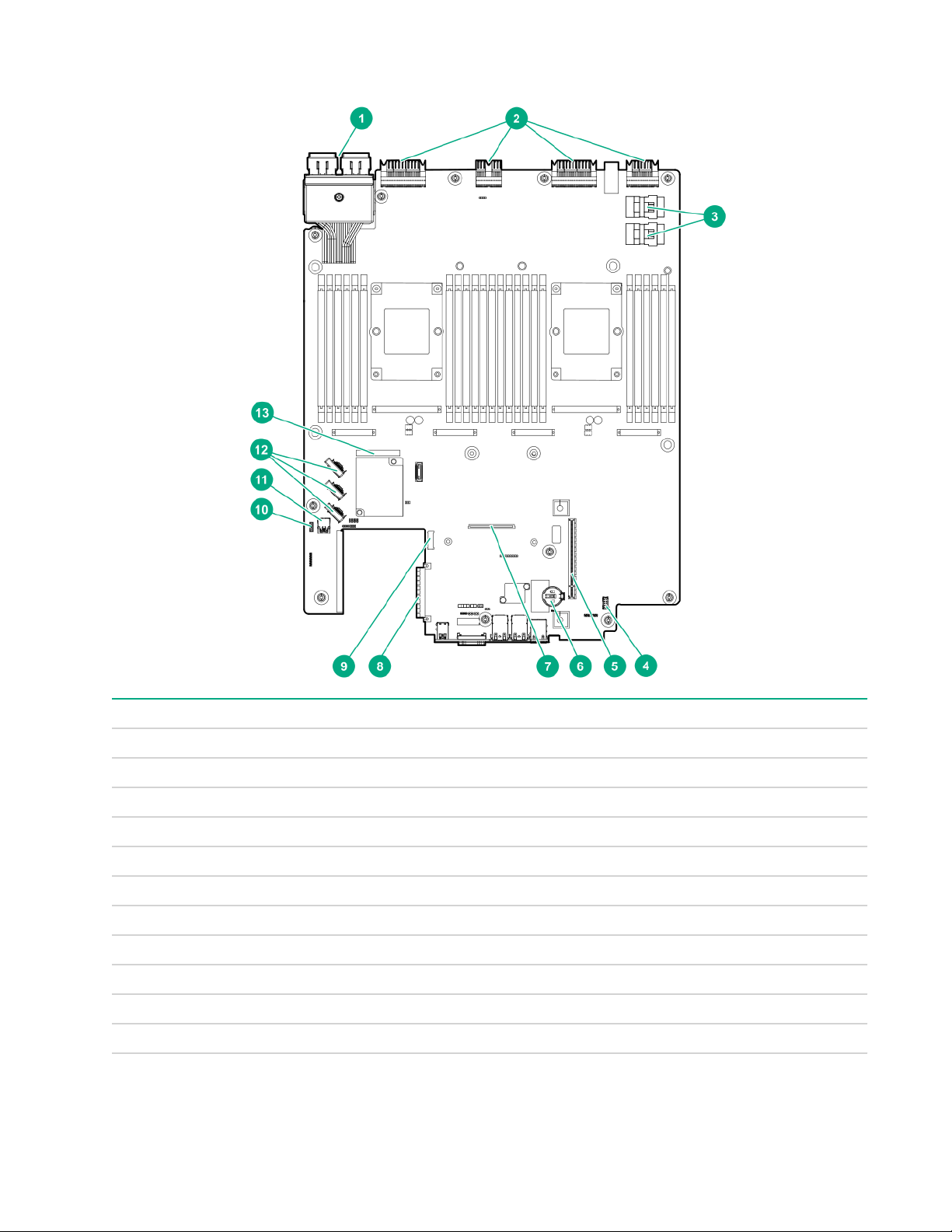
System board components
Item Description
1 Storage connector
2 Midplane connectors
3 NVMe drive ports
4 Internal communication port
5 PCIe riser cage connector
6 System battery
7 Type -a storage controller connector
8 FlexibleLOM connector
9 M.2 riser connector
10 iLO USB connector
11 Internal USB 3.0 connector
Table Continued
10 System board components

Item Description
12 X4 embedded SATA ports 1-3
13 System Maintenance Switch
System maintenance switch descriptions
Position Default Function
1
S1
Off
Off = security is enabled.
On = security is disabled.
S2 Off
Off = System configuration can be changed.
On = System configuration is locked.
S3 Off Reserved
S4 Off Reserved
1
S5
Off
Off = Power-on password is enabled.
On = Power-on password is disabled.
S61, 2,
3
Off
Off = No function
On = Restore default manufacturing settings
S7 Off Reserved
S8 — Reserved
S9 — Reserved
S10 — Reserved
S11 — Reserved
S12 — Reserved
1
To access the redundant ROM, set S1, S5, and S6 to On.
2
When the system maintenance switch position 6 is set to the On position, the system is prepared to restore all
configuration settings to their manufacturing defaults.
3
When the system maintenance switch position 6 is set to the On position and Secure Boot is enabled, some
configurations cannot be restored. For more information, see Secure Boot on page 78.
NMI functionality
An NMI crash dump enables administrators to create crash dump files when a system is hung and not
responding to traditional debugging methods.
An analysis of the crash dump log is an essential part of diagnosing reliability problems, such as hanging
operating systems, device drivers, and applications. Many crashes freeze a system, and the only available
action for administrators is to cycle the system power. Resetting the system erases any information that could
support problem analysis, but the NMI feature preserves that information by performing a memory dump
before a hard reset.
To force the OS to invoke the NMI handler and generate a crash dump log, the administrator can use the iLO
Virtual NMI feature.
System maintenance switch descriptions 11
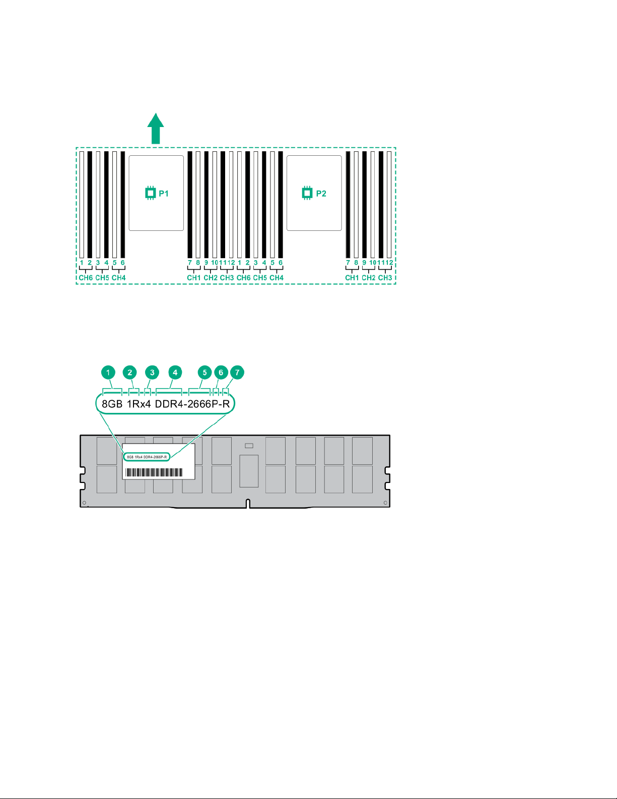
DIMM slot locations
DIMM slots are numbered sequentially (1 through 12) for each processor. The supported AMP modes use the
letter assignments for population guidelines.
The arrow indicates the front of the server.
DIMM label identification
To determine DIMM characteristics, see the label attached to the DIMM. The information in this section helps
you to use the label to locate specific information about the DIMM.
12 DIMM slot locations

Item Description Example
1 Capacity
2 Rank
3 Data width on DRAM
4 Memory generation
5 Maximum memory speed
8 GB
16 GB
32 GB
64 GB
128 GB
1R = Single rank
2R = Dual rank
4R = Quad rank
8R = Octal rank
x4 = 4-bit
x8 = 8-bit
x16 = 16-bit
PC4 = DDR4
2133 MT/s
2400 MT/s
2666 MT/s
6 CAS latency
7 DIMM type
For more information about product features, specifications, options, configurations, and compatibility, see the
product QuickSpecs on the Hewlett Packard Enterprise website (http://www.hpe.com/info/qs).
P = CAS 15-15-15
T = CAS 17-17-17
U = CAS 20-18-18
V = CAS 19-19-19 (for RDIMM, LRDIMM)
V = CAS 22-19-19 (for 3DS TSV LRDIMM)
R = RDIMM (registered)
L = LRDIMM (load reduced)
E = Unbuffered ECC (UDIMM)
Component identification 13
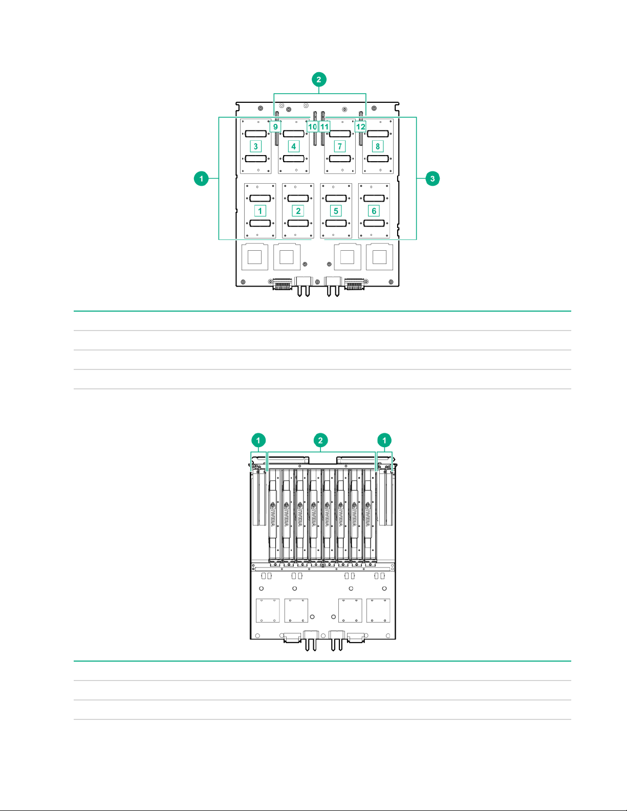
SXM2 GPU module components
Item Description
1 SXM2 GPU slots 1-4
2 PCIe slots 9-12
3 SXM2 GPU slots 5-8
PCIe GPU module components
Item Description
1 Low-profile PCIe Gen3 slots 9-12
2 PCIe GPU slots 1-8
14 SXM2 GPU module components
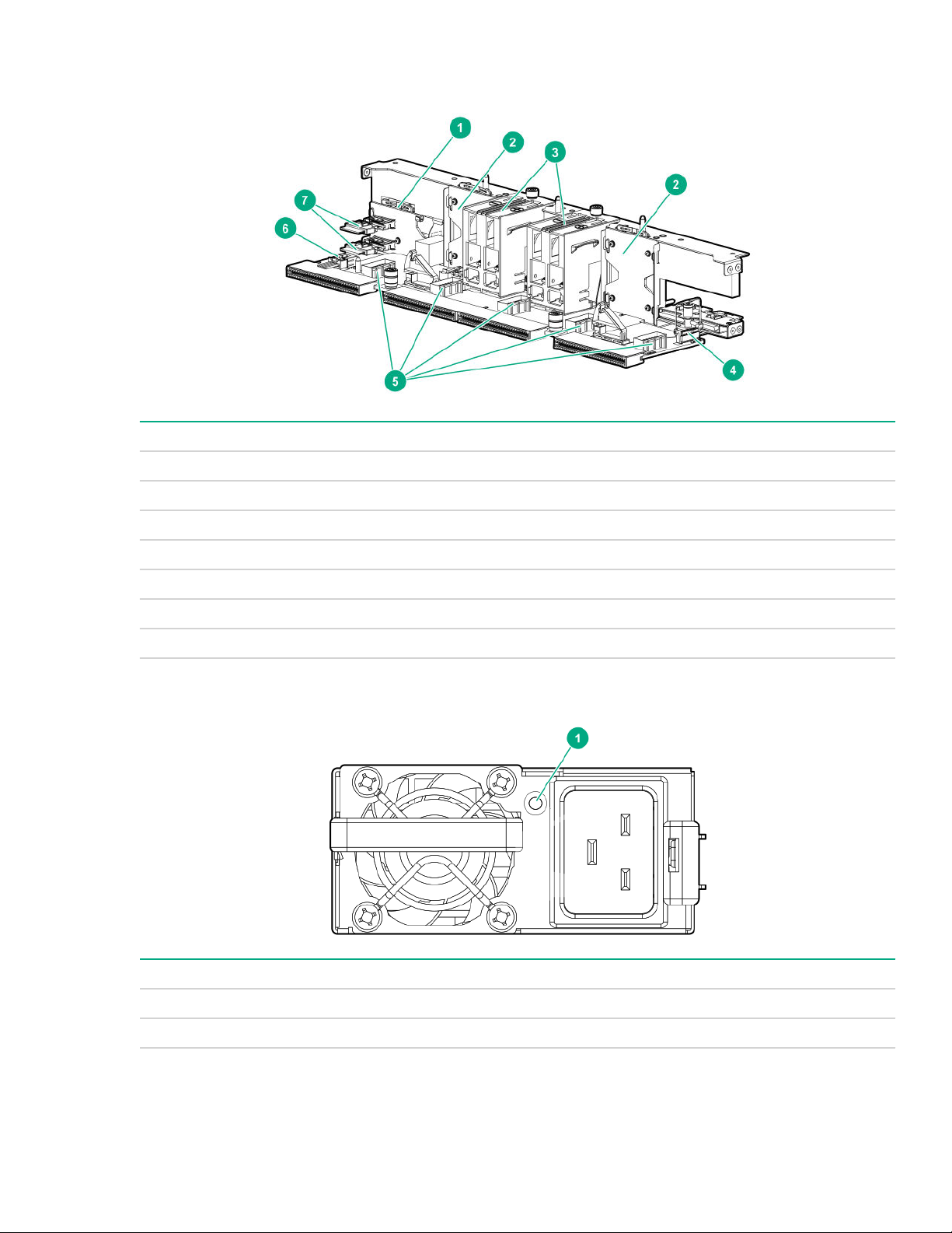
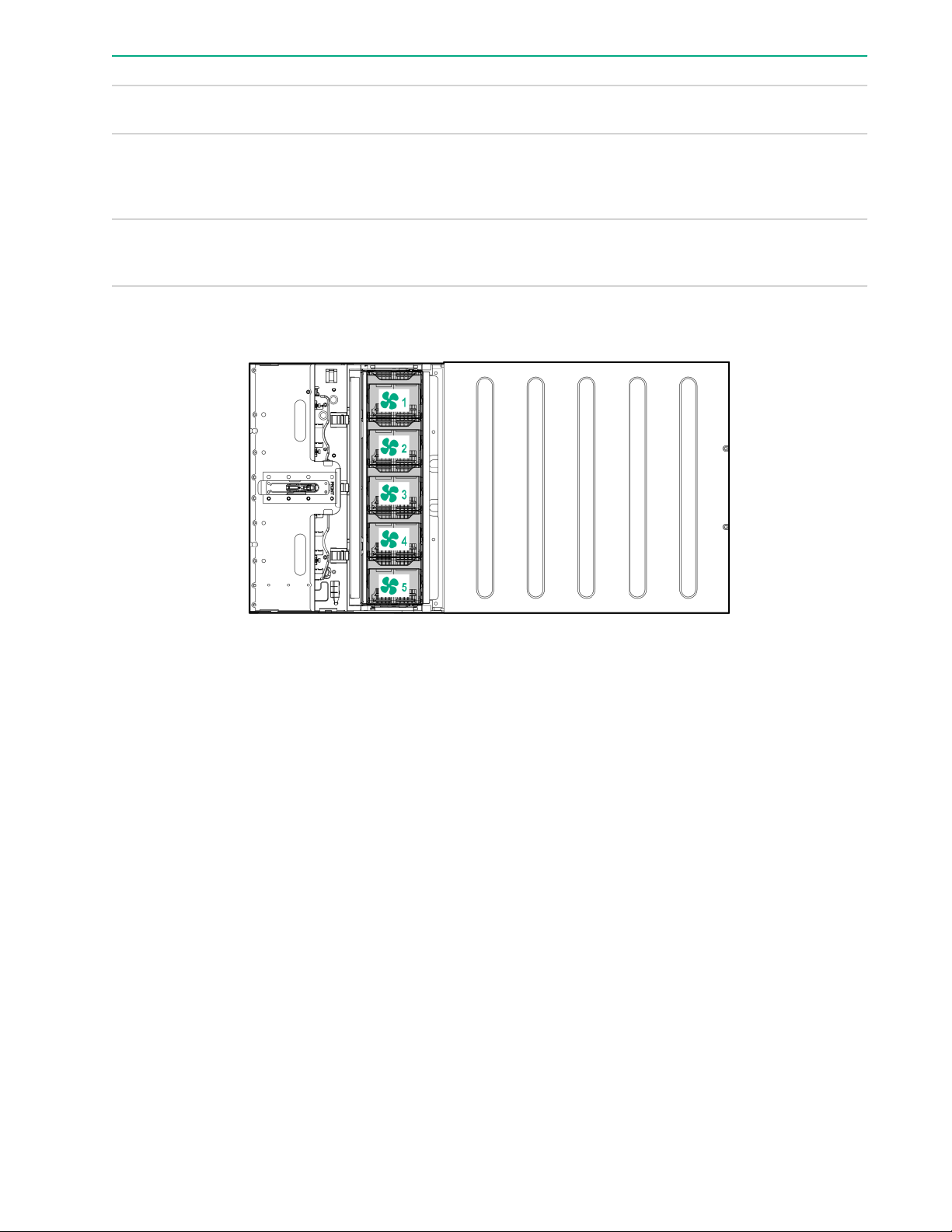
Power distribution board and bus bar components
Item Description
1 NVMe midplane
2 Processor/GPU midplane
3 Power busbars to GPU module
4 Front panel LED connector
5 Fan connectors 1-5
6 HPE Smart Storage Battery connector
7 NVMe port cable connectors
Power supply LED
Status Description
Solid green Power supply is on and is operating normally.
Flashing green (0.5 Hz) 12 V standby power present (Power supply off)
Table Continued
Power distribution board and bus bar components 15
Status Description
Flashing green (2 Hz) Power supply is in Smart redundant state or offline
Solid amber 12 V fault caused a shutdown; power supply failed
Off No power present or standby power failed
Fan module numbering
mode.
(overvoltage/undervoltage, overtemperature,
overcurrent, short-circuit), fan failed, or input
overvoltage protection
(overvoltage/undervoltage, overtemperature,
overcurrent, short-circuit, fan lock)
Supported drives
When one drive cage is installed, the following drive configurations are supported:
• 2 NVMe + 6 SATA
• 2 NVMe + 6 SAS
• 8 SAS/SATA when one of the following controllers is installed
◦ P408i-p
◦ P408i-a
◦ P816i-a
• Embedded SATA: 6 SATA drives
When two drive cages are installed, the following drive configurations are supported:
• 4 NVMe (2/2) + 12 SATA (6/4)
• 4 NVMe (2/2) + 12 SAS (6/6)
• 16 SATA (p816i-a)
16 Fan module numbering
• 16 SAS/SATA (p408i-a + p408i-p)
• Embedded SATA: 12 SATA (6/6)
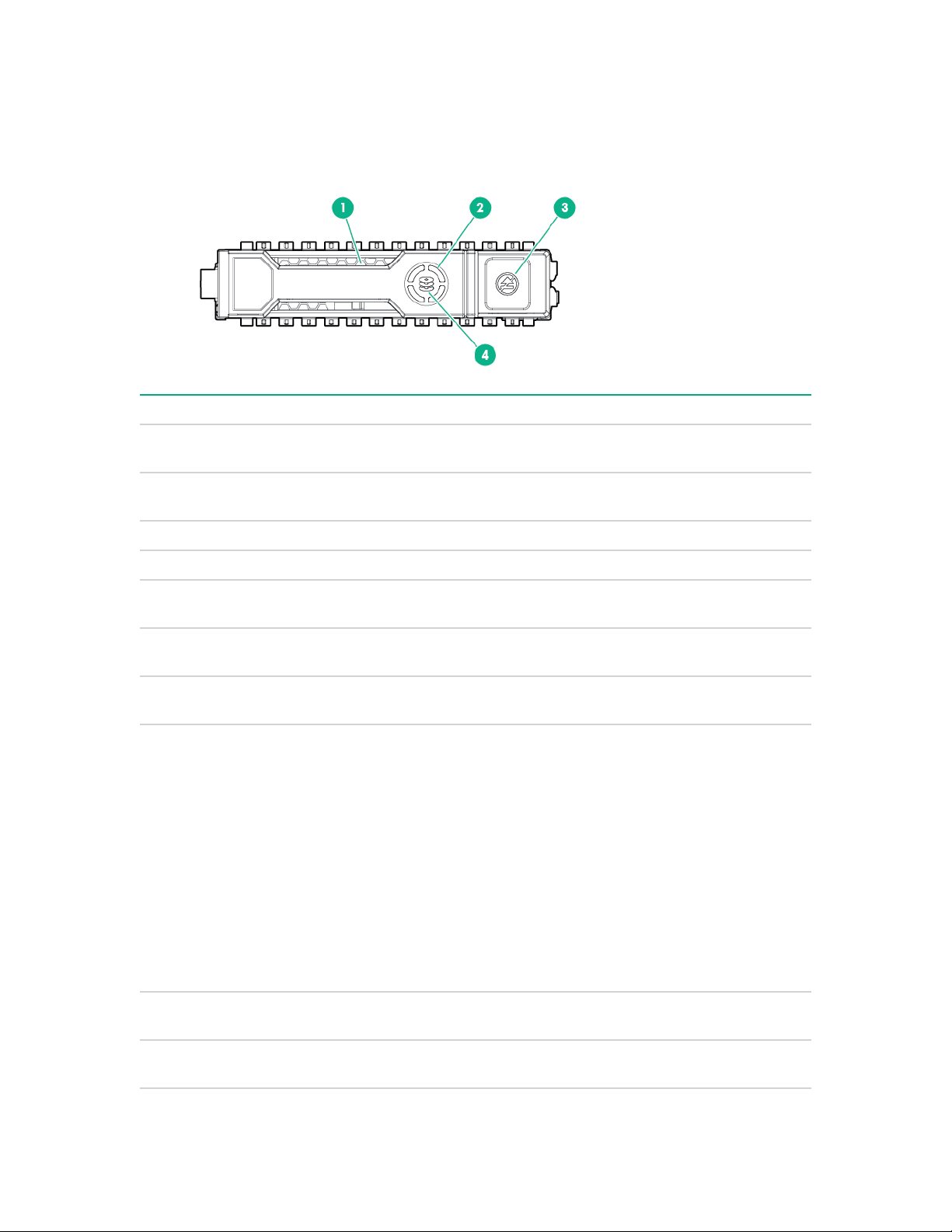
Hot-plug drive LED definitions
Item LED Status Definition
1 Locate Solid blue The drive is being identified by a host
Flashing blue The drive carrier firmware is being updated or
application.
requires an update.
2 Activity ring Rotating green Drive activity.
Off No drive activity.
3 Do not remove Solid white Do not remove the drive. Removing the drive
causes one or more of the logical drives to fail.
Off Removing the drive does not cause a logical
drive to fail.
4 Drive status Solid green The drive is a member of one or more logical
drives.
Flashing green The drive is doing one of the following:
• Rebuilding
• Performing a RAID migration
• Performing a strip size migration
• Performing a capacity expansion
• Performing a logical drive extension
• Erasing
• Spare part activation
Flashing amber/
green
Flashing amber The drive is not configured and predicts the
The drive is a member of one or more logical
drives and predicts the drive will fail.
drive will fail.
Table Continued
Hot-plug drive LED definitions 17
Item LED Status Definition
Solid amber The drive has failed.
Off The drive is not configured by a RAID
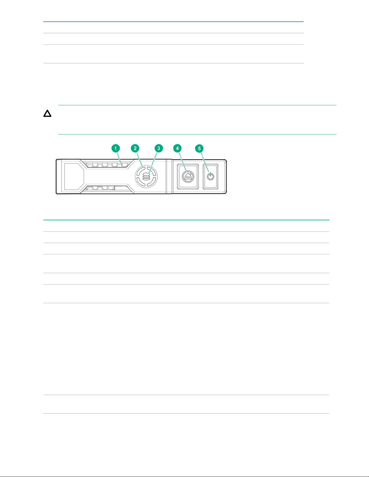
NVMe SSD LED definitions
The NVMe SSD is a PCIe bus device. A device attached to a PCIe bus cannot be removed without allowing
the device and bus to complete and cease the signal/traffic flow.
CAUTION: Do not remove an NVMe SSD from the drive bay while the Do not remove LED is flashing.
The Do not remove LED flashes to indicate that the device is still in use. Removing the NVMe SSD
before the device has completed and ceased signal/traffic flow can cause loss of data.
controller or a spare drive.
Item LED Status Definition
1 Locate Solid blue The drive is being identified by a host application.
Flashing blue The drive carrier firmware is being updated or requires an update.
2 Activity
ring
Off No drive activity
3 Drive
status
Flashing green The drive is doing one of the following:
Rotating green Drive activity
Solid green The drive is a member of one or more logical drives.
• Rebuilding
• Performing a RAID migration
• Performing a stripe size migration
• Performing a capacity expansion
• Performing a logical drive extension
• Erasing
Flashing amber/
green
18 NVMe SSD LED definitions
The drive is a member of one or more logical drives and predicts the
drive will fail.
Table Continued

Item LED Status Definition
Flashing amber The drive is not configured and predicts the drive will fail.
Solid amber The drive has failed.
Off The drive is not configured by a RAID controller.
4 Do not
remove
Flashing white The drive ejection request is pending.
5 Power Solid green Do not remove the drive. The drive must be ejected from the PCIe bus
Solid white Do not remove the drive. The drive must be ejected from the PCIe bus
prior to removal.
Off The drive has been ejected.
prior to removal.
Flashing green The drive ejection request is pending.
Off The drive has been ejected.
Component identification 19

Operations
Power up the server
To power up the server, use one of the following methods:
• Press the Power On/Standby button.
• Use the virtual power button through iLO.
Power down the server
Before powering down the server for any upgrade or maintenance procedures, perform a backup of critical
server data and programs.
IMPORTANT: When the server is in standby mode, auxiliary power is still being provided to the system.
To power down the server, use one of the following methods:
• Press and release the Power On/Standby button.
This method initiates a controlled shutdown of applications and the OS before the server enters standby
mode.
• Press and hold the Power On/Standby button for more than 4 seconds to force the server to enter standby
mode.
This method forces the server to enter standby mode without properly exiting applications and the OS. If
an application stops responding, you can use this method to force a shutdown.
• Use a virtual power button selection through .
This method initiates a controlled remote shutdown of applications and the OS before the server enters
standby mode.
Before proceeding, verify that the server is in standby mode by observing that the system power LED is
amber.
Extending the chassis from the rack
Procedure
Loosen the thumbscrews on either side of the chassis, and then extend the chassis from the rack.
20 Operations
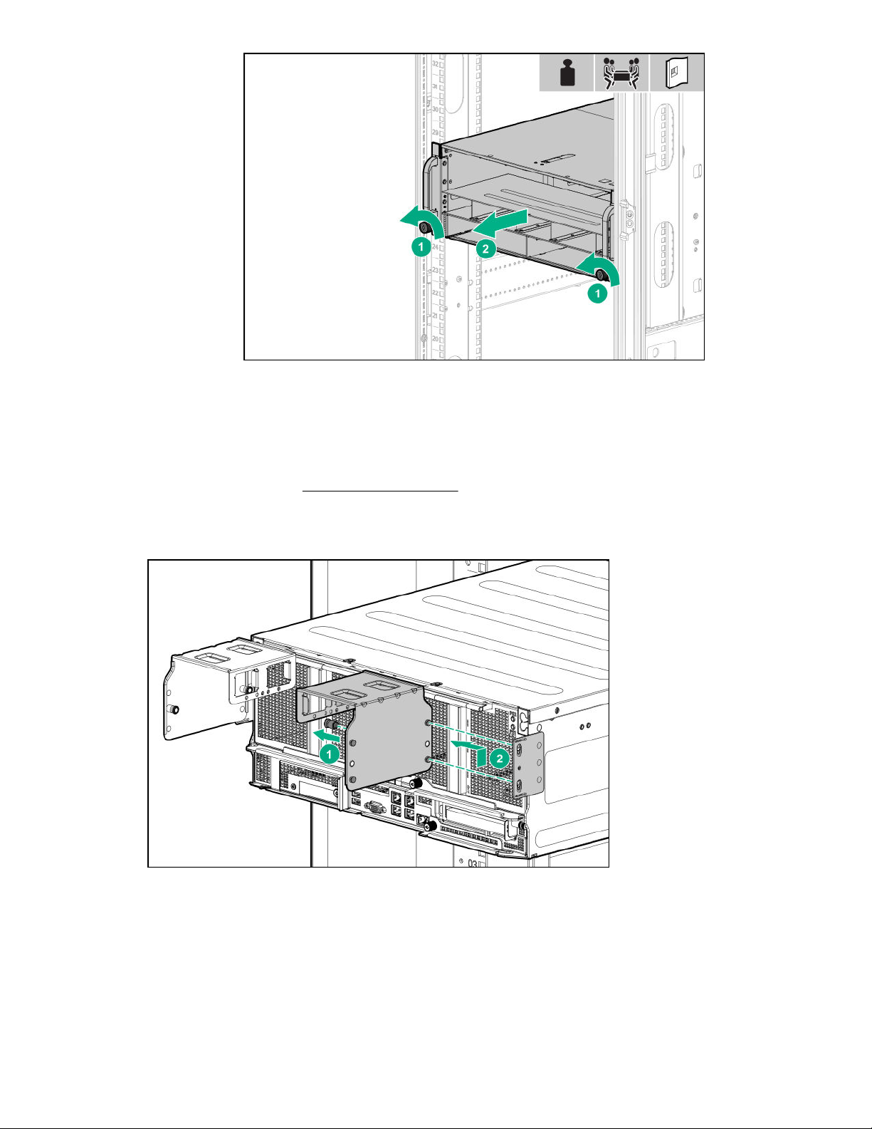
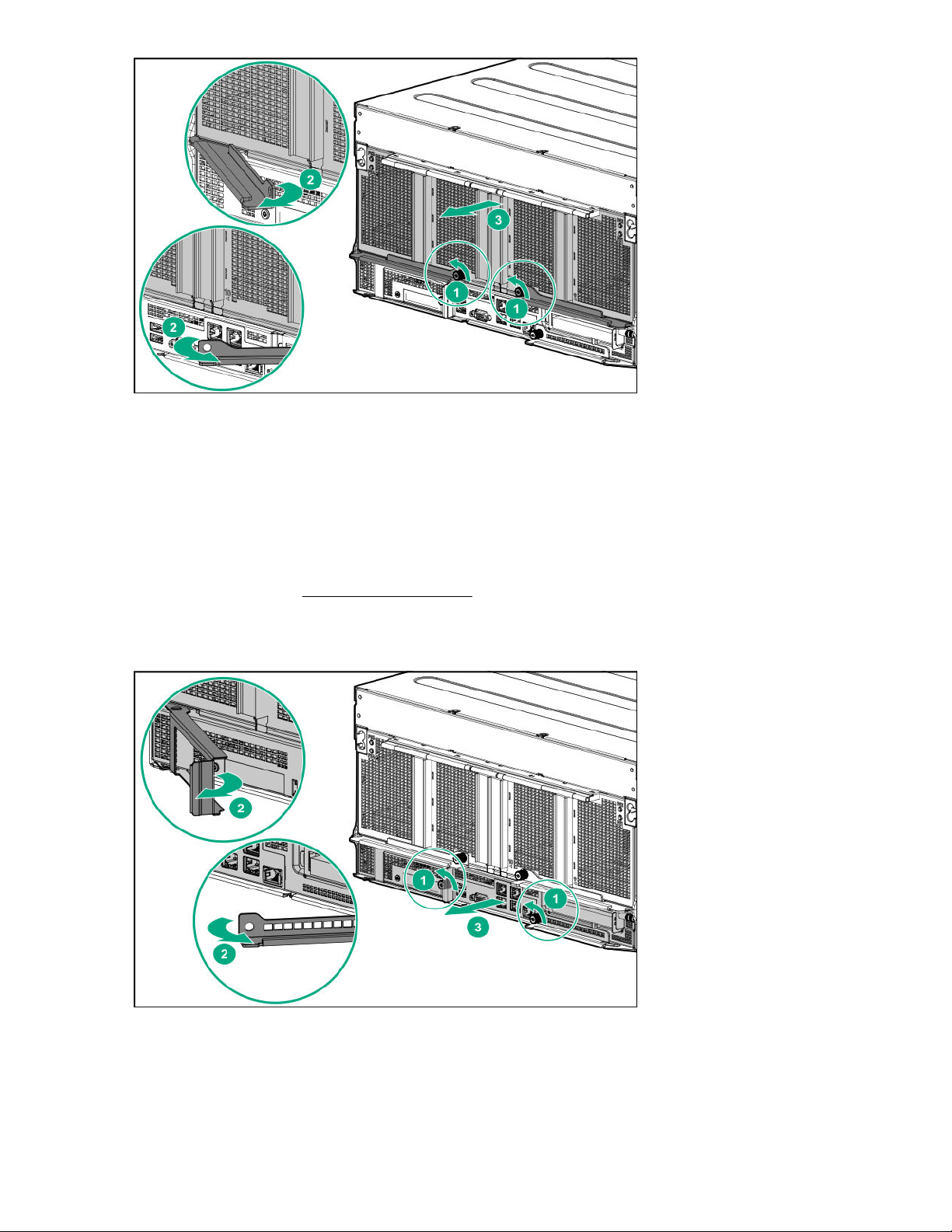
Removing the GPU module from the chassis
Procedure
1. Power down the server (Power down the server on page 20).
2. Disconnect all peripheral cables from the GPU module.
3. If installed, remove the power cord guides.
4. Remove the GPU module from the chassis.
Depending on the chassis configuration, your GPU module might look different.
Removing the GPU module from the chassis 21
5. Place the module on a flat, level work surface.
Removing the system board module from the chassis
Procedure
1. Back up all server data.
2. Power down the server (Power down the server on page 20).
3. Disconnect all peripheral cables from the server.
4. Remove the server from the chassis.
5. Place the module on a flat, level work surface.
22 Removing the system board module from the chassis
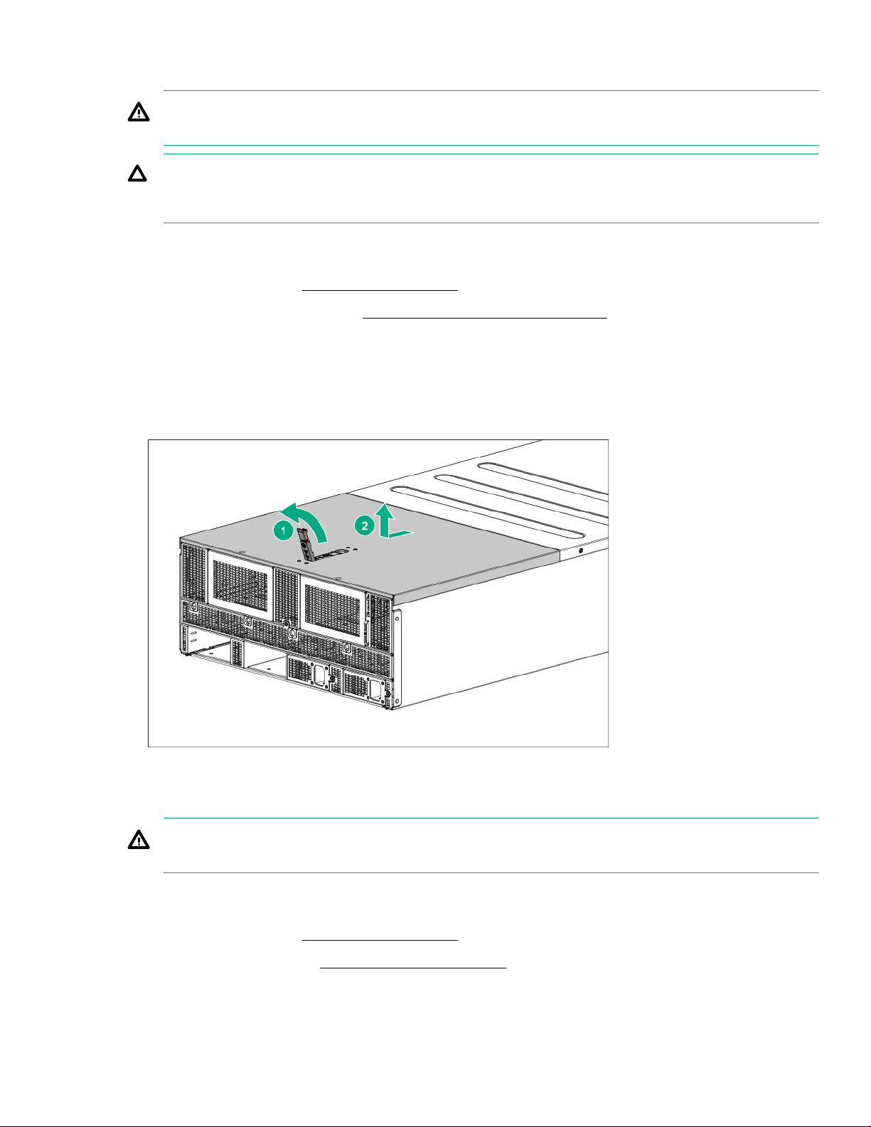
Removing the access panel
WARNING: To reduce the risk of personal injury from hot surfaces, allow the drives and the internal
system components to cool before touching them.
CAUTION: Do not operate the chassis for long periods with the access panel open or removed.
Operating the chassis in this manner results in improper airflow and improper cooling that can lead to
thermal damage.
Procedure
1. Power down the server (Power down the server on page 20).
2. Extend the chassis from the rack (Extending the chassis from the rack on page 20).
3. If the locking latch is locked, use a T-15 Torx screwdriver to unlock the latch.
4. Open the locking latch.
The access panel slides back, releasing it from the chassis.
5. Lift and remove the access panel.
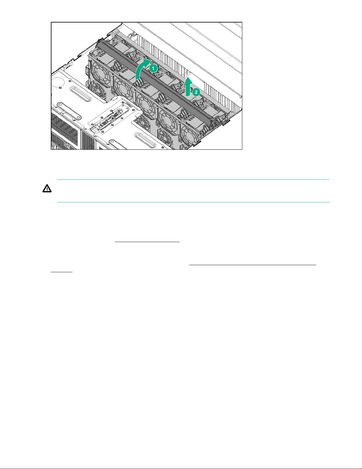
Removing the fan cage
WARNING: To reduce the risk of personal injury from hot surfaces, allow the drives and the internal
system components to cool before touching them.
Procedure
1. Power down the server (Power down the server on page 20).
2. Remove the access panel (Removing the access panel on page 23).
3. Remove the fan cage.
Removing the access panel 23
Removing the riser cage
WARNING: To reduce the risk of personal injury from hot surfaces, allow the drives and the internal
system components to cool before touching them.
Procedure
1. Back up all server data.
2. Power down the server (Power down the server on page 20).
3. Disconnect all peripheral cables from the server.
4. Remove the system board module from the chassis (Removing the system board module from the
chassis on page 22).
5. Place the module on a flat, level work surface.
6. Remove the riser cage.
24 Removing the riser cage
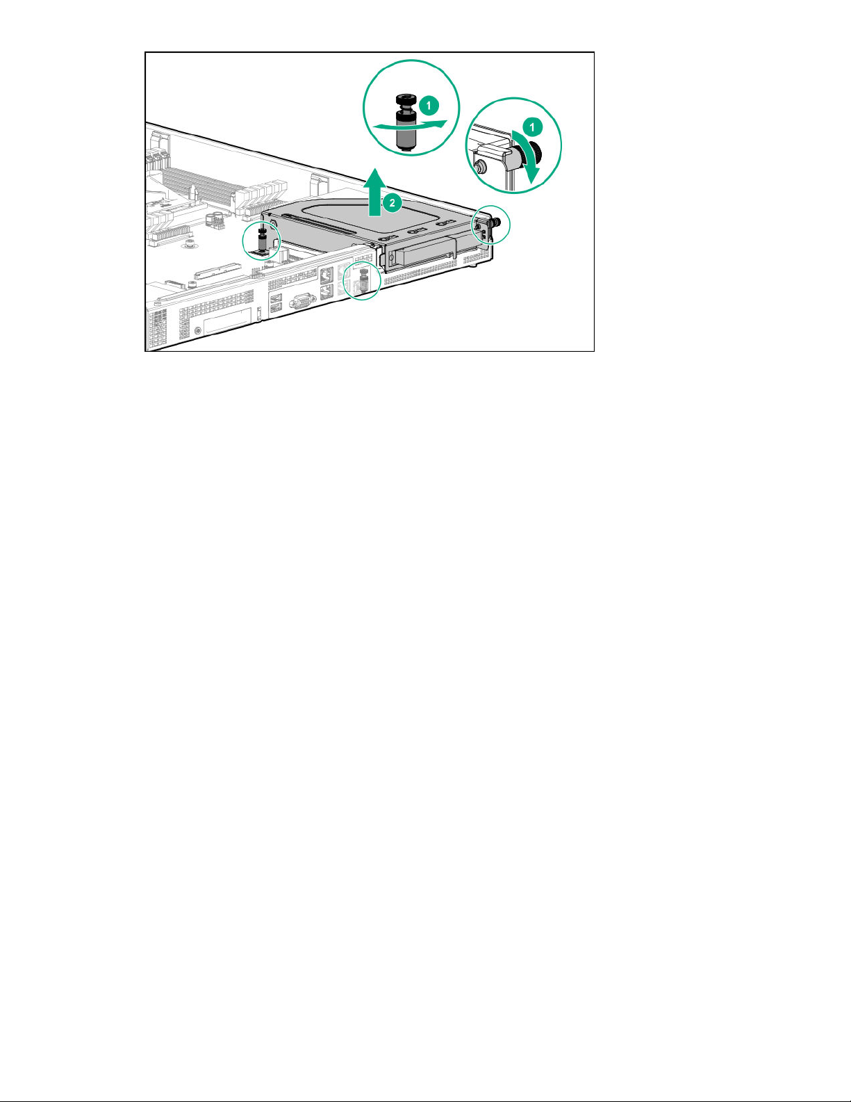
To replace the component, reverse the removal procedure.
Operations 25

Setup
Safety and regulatory compliance
For important safety, environmental, and regulatory information, see Safety and Compliance Information for
Server, Storage, Power, Networking, and Rack Products, available at the Hewlett Packard Enterprise website
http://www.hpe.com/support/Safety-Compliance-EnterpriseProducts).
(
Optional service
Delivered by experienced, certified engineers, Hewlett Packard Enterprise support services help you keep
your servers up and running with support packages tailored specifically for HPE ProLiant systems. Hewlett
Packard Enterprise support services let you integrate both hardware and software support into a single
package. A number of service level options are available to meet your business and IT needs.
Hewlett Packard Enterprise support services offer upgraded service levels to expand the standard product
warranty with easy-to-buy, easy-to-use support packages that will help you make the most of your server
investments. Some of the Hewlett Packard Enterprise support services for hardware, software or both are:
• Foundation Care – Keep systems running.
◦ 6-Hour Call-to-Repair
◦ 4-Hour 24x7
◦ Next Business Day
• Proactive Care – Help prevent service incidents and get you to technical experts when there is one.
◦ 6-Hour Call-to-Repair
◦ 4-Hour 24x7
◦ Next Business Day
• Deployment service for both hardware and software
• Hewlett Packard Enterprise Education Services – Help train your IT staff.
1
The time commitment for this repair service might vary depending on the site's geographical region. For
more service information available in your site, contact your local Hewlett Packard Enterprise support
center.
For more information on Hewlett Packard Enterprise support services, see the Hewlett Packard Enterprise
website.
1
1
Warnings and cautions
WARNING: To reduce the risk of personal injury or damage to equipment, heed all warnings and
cautions throughout the installation instructions.
26 Setup
WARNING: To reduce the risk of personal injury or damage to the equipment, be sure that:
• The rack is bolted to the floor using the concrete anchor kit.
• The leveling feet extend to the floor.
• The full weight of the rack rests on the leveling feet.
• The racks are coupled together in multiple rack installations.
• Only one component is extended at a time. If more than one component is extended, a rack might
become unstable.
WARNING: The chassis is very heavy. To reduce the risk of personal injury or damage to the
equipment:
• Observe local occupational health and safety requirements and guidelines for manual material
handling.
• Remove all servers from the chassis before installing or moving the chassis.
• Use caution and get help to lift and stabilize the chassis during installation or removal, especially
when the chassis is not fastened to the rack.
WARNING: To reduce the risk of personal injury or damage to the equipment, you must adequately
support the chassis during installation and removal.
WARNING: Install the chassis starting from the bottom of the rack and work your way up the rack.
WARNING: To reduce the risk of personal injury from hot surfaces, allow the drives and the internal
system components to cool before touching them.
WARNING: To reduce the risk of electric shock or damage to the equipment:
• Never reach inside the chassis while the system is powered up.
• Perform service on system components only as instructed in the user documentation.
CAUTION: Always be sure that equipment is properly grounded and that you follow proper grounding
procedures before beginning any installation procedure. Improper grounding can result in ESD damage
to electronic components. For more information, refer to "Electrostatic discharge on page 88."
CAUTION: When performing non-hot-plug operations, you must power down the server and/or the
system. However, it may be necessary to leave the server powered up when performing other
operations, such as hot-plug installations or troubleshooting.
CAUTION: Do not operate the server for long periods with the access panel open or removed.
Operating the server in this manner results in improper airflow and improper cooling that can lead to
thermal damage.
Setup 27

Determining power and cooling configurations
Validate power and cooling requirements based on location and installed components.
Power requirements
Installation of this equipment must comply with local and regional electrical regulations governing the
installation of IT equipment by licensed electricians. This equipment is designed to operate in installations
covered by NFPA 70, 1999 Edition (National Electric Code) and NFPA-75, 1992 (code for Protection of
Electronic Computer/Data Processing Equipment). For electrical power ratings on options, refer to the product
rating label or the user documentation supplied with that option.
WARNING: To reduce the risk of personal injury, fire, or damage to the equipment, do not overload the
AC supply branch circuit that provides power to the rack. Consult the electrical authority having
jurisdiction over wiring and installation requirements of your facility.
CAUTION: Protect the server from power fluctuations and temporary interruptions with a regulating
UPS. This device protects the hardware from damage caused by power surges and voltage spikes and
keeps the server in operation during a power failure.
HPE Modular Cooling System 300 and Apollo IT and CDU Rack system
The HPE Modular Cooling System 300 and Apollo IT and CDU Rack system is a high-density, energyefficient, sustainable high-performance computing solution that uses an innovative warm-liquid cooling
technology to fuel the future of supercomputing. It offers a modular, rack-based system that is easy to install,
maintain, and monitor. The hot water "waste heat" can be recycled to heat the data center efficiently.
For more information, see the HPE Modular Cooling System 300 and Apollo IT and CDU Rack User Guide on
the Hewlett Packard Enterprise website (http://www.hpe.com/info/XL270dGen10-docs).
HPE Apollo Environmental Module
The HPE Apollo Environmental Module is installed in the rack and connects to the rack leak detectors and
sensors to monitor environmental variables, such as temperature and humidity. This information is accessible
using the HPE Apollo Platform Manager.
For more information, see the following documentation on the Hewlett Packard Enterprise website (http://
www.hpe.com/info/XL270dGen10-docs):
• HPE Apollo Platform Manager User Guide
• HPE Modular Cooling System 300 and Apollo IT and CDU Rack User Guide
HPE Apollo System Manager
Apollo System Manager provides a comprehensive, central pane of glass to view the state of the Apollo
warm-water-cooling and power infrastructure. It also provides email alerts when preconfigured events occur.
All sensor data is gathered and archived for plotting, analysis, and to assist with any support issues.
For more information, see the HPE Apollo System Manager User Guide on the Hewlett Packard Enterprise
website (http://www.hpe.com/info/XL270dGen10-docs).
28 Determining power and cooling configurations
 Loading...