

Page 1

HP ProLiant XL220a Gen8 v2 Server User Guide
Abstract
This document is for the person who installs, administers, and troubleshoots servers and storage systems. HP assumes you are qualified in the
servicing of computer equipment and trained in recognizing hazards in products with hazardous energy levels.
Part Number: 752048-001
June 2014
Edition: 1
Page 2

© Copyright 2014 Hewlett-Packard Development Company, L.P.
The information contained herein is subject to change without notice. The only warranties for HP products and services are set forth in the express
warranty statements accompanying such products and services. Nothing herein should be construed as constituting an additional warranty. HP shall
not be liable for technical or editorial errors or omissions contained herein.
Microsoft® and Windows® are U.S. registered trademarks of Microsoft Corporation.
Page 3

Contents
Component identification ............................................................................................................... 6
Front panel components ................................................................................................................................ 6
Front panel LEDs and buttons ......................................................................................................................... 7
System board components ............................................................................................................................ 8
DIMM slot locations ............................................................................................................................ 9
System maintenance switch ................................................................................................................. 9
Drive numbering ........................................................................................................................................ 10
Hot-plug drive LED definitions ...................................................................................................................... 10
Operations................................................................................................................................. 12
Power down the server ............................................................................................................................... 12
Removing a drive blank .............................................................................................................................. 12
Remove the drive........................................................................................................................................ 13
Remove the server ...................................................................................................................................... 13
Remove the processor air baffle ................................................................................................................... 14
Remove the PCI riser board assembly ........................................................................................................... 14
Remove the drive cage assembly ................................................................................................................. 15
Install the processor air baffle ...................................................................................................................... 17
Install the PCI riser board assembly .............................................................................................................. 17
Install the server ......................................................................................................................................... 18
Setup ......................................................................................................................................... 20
Setup overview .......................................................................................................................................... 20
Installing the chassis into a rack ................................................................................................................... 20
Installing hardware options ......................................................................................................................... 20
Installing I/O modules and connecting them to the network ............................................................................ 20
Installing a server ....................................................................................................................................... 20
Powering up the chassis .............................................................................................................................. 21
Installing the operating system ..................................................................................................................... 22
Installing the system software ....................................................................................................................... 22
Registering the server.................................................................................................................................. 22
Hardware options installation ....................................................................................................... 23
Introduction ............................................................................................................................................... 23
Processor option......................................................................................................................................... 23
Memory options ......................................................................................................................................... 26
Memory subsystem architecture ......................................................................................................... 27
Single-rank and dual-rank DIMMs ...................................................................................................... 27
DIMM identification .......................................................................................................................... 27
ECC memory ................................................................................................................................... 28
General DIMM slot population guidelines ........................................................................................... 28
Installing a DIMM ............................................................................................................................. 28
Drives ....................................................................................................................................................... 29
Drive guidelines ............................................................................................................................... 30
Installing a hot-plug drive .................................................................................................................. 30
Controller options ....................................................................................................................................... 31
FBWC cache module and capacitor pack option ................................................................................. 32
Contents 3
Page 4

HP Trusted Platform Module option .............................................................................................................. 34
Installing the Trusted Platform Module board ....................................................................................... 35
Retaining the recovery key/password ................................................................................................. 36
Enabling the Trusted Platform Module ................................................................................................. 36
Software and configuration utilities ............................................................................................... 38
Server mode .............................................................................................................................................. 38
Product QuickSpecs .................................................................................................................................... 38
HP iLO Management .................................................................................................................................. 38
HP iLO ............................................................................................................................................ 38
Intelligent Provisioning ...................................................................................................................... 40
HP Insight Remote Support software ................................................................................................... 41
HP Insight Online ............................................................................................................................. 42
Scripting Toolkit for Windows and Linux ............................................................................................. 42
HP Service Pack for ProLiant ........................................................................................................................ 43
HP Smart Update Manager ............................................................................................................... 43
HP ROM-Based Setup Utility ........................................................................................................................ 43
Using RBSU ..................................................................................................................................... 44
Auto-configuration process ................................................................................................................ 44
Boot options .................................................................................................................................... 45
Configuring AMP modes ................................................................................................................... 45
Re-entering the server serial number and product ID ............................................................................. 45
Utilities and features ................................................................................................................................... 46
Array Configuration Utility ................................................................................................................ 46
HP Smart Storage Administrator ......................................................................................................... 47
Option ROM Configuration for Arrays................................................................................................ 47
ROMPaq utility ................................................................................................................................. 47
Automatic Server Recovery ................................................................................................................ 48
USB support .................................................................................................................................... 48
Redundant ROM support ................................................................................................................... 48
Keeping the system current .......................................................................................................................... 49
Drivers ............................................................................................................................................ 49
Software and firmware ..................................................................................................................... 49
Version control ................................................................................................................................. 49
HP operating systems and virtualization software support for ProLiant servers ......................................... 50
HP Technology Service Portfolio ......................................................................................................... 50
Change control and proactive notification .......................................................................................... 50
Troubleshooting .......................................................................................................................... 51
Troubleshooting resources ........................................................................................................................... 51
Cabling ..................................................................................................................................... 52
Internal server cabling ................................................................................................................................ 52
Drive cabling ................................................................................................................................... 52
Front panel LED board assembly cabling ............................................................................................ 53
FBWC capacitor pack cabling........................................................................................................... 53
SUV cable connectors ................................................................................................................................. 53
Regulatory information ................................................................................................................ 55
Safety and regulatory compliance ................................................................................................................ 55
Belarus Kazakhstan Russia marking .............................................................................................................. 55
Turkey RoHS material content declaration ..................................................................................................... 56
Ukraine RoHS material content declaration ................................................................................................... 56
Warranty information ................................................................................................................................. 56
Contents 4
Page 5

Electrostatic discharge ................................................................................................................. 57
Preventing electrostatic discharge ................................................................................................................ 57
Grounding methods to prevent electrostatic discharge .................................................................................... 57
Specifications ............................................................................................................................. 58
Environmental specifications ........................................................................................................................ 58
Server specifications ................................................................................................................................... 58
Support and other resources ........................................................................................................ 59
Before you contact HP ................................................................................................................................ 59
HP contact information ................................................................................................................................ 59
Customer Self Repair .................................................................................................................................. 59
Acronyms and abbreviations ........................................................................................................ 67
Documentation feedback ............................................................................................................. 71
Index ......................................................................................................................................... 72
Contents 5
Page 6
Component identification
3
5
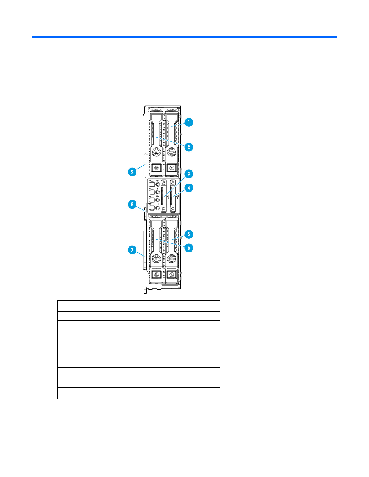
Front panel components
Item Description
1
2
4
6
7
8
9
Drive bay 2 (node 1)
Drive bay 1 (node 1)
SUV connector (node 1)
SUV connector (node 2)
Drive bay 2 (node 2)
Drive bay 1 (node 2)
Server release lever
Server release latch
Serial label pull tab
Component identification 6
Page 7

Front panel LEDs and buttons
Item Description Status
1
2
3
4
5
NIC 1 LED (node 1) Solid green = Link to network
Flashing green (1 Hz/cycle per sec) = Network active
Off = No network activity
Health LED (node 1) Solid green = Normal
Flashing amber = System degraded
Flashing red (1 Hz/cycle per sec) = System critical
Fast-flashing red (4 Hz/cycles per sec) = Power fault
NIC 2 LED (node 2) Solid green = Link to network
Flashing green (1 Hz/cycle per sec) = Network active
Off = No network activity
Health LED (node 2) Solid green = Normal
Flashing amber = System degraded
Flashing red (1 Hz/cycle per sec) = System critical
Fast-flashing red (4 Hz/cycles per sec) = Power fault
UID button/LED (node 2) Solid blue = Activated
Flashing blue (1 Hz/cycle per sec) = Remote
management or firmware upgrade in progress
Off = Deactivated
Component identification 7
Page 8

Item Description Status
4
12
6
7
8
Power On/Standby button and system
power LED (node 2)
UID button/LED (node 1) Solid blue = Activated
Power On/Standby button and system
power LED (node 1)
System board components
Solid green = System on
Flashing green (1 Hz/cycle per sec) = Performing
power on sequence
Solid amber = System in standby
Off = No power present
Flashing blue (1 Hz/cycle per sec) = Remote
management or firmware upgrade in progress
Off = Deactivated
Solid green = System on
Flashing green (1 Hz/cycle per sec) = Performing
power on sequence
Solid amber = System in standby
Off = No power present
Item Description
1
2
3
5
6
7
8
9
10
11
13
14
15
Micro SD card slot (node 1)
Front panel LED board cable connector (node 1)
Front panel LED board cable connector (node 2)
Drive backplane power connector (node 1)
PCIe riser board connector (node 1)
System maintenance switch (node 1)
TPM (node 1)
DIMMs (node 1)
Processor 1 (node 1)
Processor 2 (node 2)
DIMMs (node 2)
System battery (node 2)
System battery (node 1)
Micro SD card slot (node 2)
TPM (node 2)
Component identification 8
Page 9

Item Description
16
17
18
PCIe riser board connector (node 2)
System maintenance switch (node 2)
Drive backplane power connector (node 2)
DIMM slot locations
DIMM slots are numbered sequentially (1 through 4) for each processor. The supported AMP modes use the
alpha assignments for population order, and the slot numbers designate the DIMM slot ID for spare
replacement. The arrow indicates the front of the server.
System maintenance switch
Switch Default Function
1
2
5
6
3, 4, 7, 8, 9,
10, 11, 12
When the system maintenance switch position 6 is set to the On position, the system is prepared to erase all
system configuration settings from both CMOS and NVRAM.
Off Off = No function
On = iLO 4 security is disabled
Off Off = System configuration can be
changed
On = System configuration is locked
Off Off = Power-on password is enabled
On = Power-on password is disabled
Off Off = No function
On = ROM reads configuration as
invalid
— Reserved
CAUTION: Clearing CMOS and/or NVRAM deletes configuration information. Be sure to
properly configure the server or data loss could occur.
Component identification 9
Page 10

Drive numbering
Item Description
1
2
3
4
Drive bay 2 (node 1)
Drive bay 1 (node 1)
Drive bay 1 (node 2)
Drive bay 2 (node 2)
Hot-plug drive LED definitions
Component identification 10
Page 11

The drive is rebuilding or performing a RAID migration, strip size
Item LED Status Definition
1
2
3
4
Locate Solid blue The drive is being identified by a host application.
Flashing blue The drive carrier firmware is being updated or requires an update.
Activity ring Rotating green Drive activity
Off No drive activity
Do not remove Solid white Do not remove the drive. Removing the drive causes one or more of
the logical drives to fail.
Off Removing the drive does not cause a logical drive to fail.
Drive status Solid green The drive is a member of one or more logical drives.
Flashing green
migration, capacity expansion, or logical drive extension, or is
erasing.
Flashing
amber/green
The drive is a member of one or more logical drives and predicts
the drive will fail.
Flashing amber The drive is not configured and predicts the drive will fail.
Solid amber The drive has failed.
Off The drive is not configured by a RAID controller.
Component identification 11
Page 12

Operations
Power down the server
Before powering down the server for any upgrade or maintenance procedures, perform a backup of critical
server data and programs.
IMPORTANT: When the server is in standby mode, auxiliary power is still being provided to the
To power down the server, use one of the following methods:
• Press and release the Power On/Standby button.
• Press and hold the Power On/Standby button for more than 4 seconds to force the server to enter
system.
This method initiates a controlled shutdown of applications and the OS before the server enters standby
mode.
standby mode.
This method forces the server to enter standby mode without properly exiting applications and the OS.
If an application stops responding, you can use this method to force a shutdown.
• Use a virtual power button selection through iLO 4.
This method initiates a controlled remote shutdown of applications and the OS before the server enters
standby mode.
Before proceeding, verify the server is in standby mode by observing that the system power LED is amber.
Removing a drive blank
Remove the component as indicated.
CAUTION: To prevent improper cooling and thermal damage, do not operate the server unless
all bays are populated with either a component or a blank.
Operations 12
Page 13

Remove the drive
1. Determine the status of the drive from the drive LED definitions ("Hot-plug drive LED definitions" on page
10).
2. Back up all data on the drive.
3. Remove the drive.
Remove the server
Operations 13
Page 14

Remove the processor air baffle
1. Power down the server (on page 12).
2. Disconnect all peripheral cables from the server.
3. Remove the server (on page 13).
4. Remove the processor air baffle.
Remove the PCI riser board assembly
1. Power down the server (on page 12).
2. Disconnect all peripheral cables from the server.
3. Remove the server (on page 13).
4. Place the server on a flat, level work surface.
5. Disconnect all cables connected to existing expansion boards.
IMPORTANT: Both T-10 and T-15 screws are required for this procedure. When replacing the
component, be sure to install the screws in the proper location. Failure to do so will cause the
server to not install properly into the chassis.
Operations 14
Page 15

6.
Remove the PCI riser board assembly. A T-10 screwdriver (for horizontal screws) and a T-15
screwdriver (for vertical screws) are required for this procedure.
Remove the drive cage assembly
1. Back up all server data on the drive.
2. Power down the server (on page 12).
3. Disconnect all peripheral cables from the server.
4. Remove the server (on page 13).
5. Place the server on a flat, level work surface.
6. Remove the PCI riser board assembly (on page 14).
7. Disconnect all cables from the drive cage backplane.
Operations 15
Page 16

8.
Disconnect the front panel LED board assembly cables.
9. Remove all drives ("Remove the drive" on page 13).
10. Remove the drive cage assembly.
To replace the component, reverse the removal procedure.
Operations 16
Page 17

Install the processor air baffle
1. Install the processor air baffle.
IMPORTANT: If the DIMM latches are not fully closed, the baffle will not sit properly.
2. Install the server into the chassis ("Install the server" on page 18).
3. Connect all peripheral cables to the server.
4. Press the Power On/Standby button.
The server exits standby mode and applies full power to the system. The system power LED changes
from amber to green.
Install the PCI riser board assembly
1. Align the PCI riser board with the corresponding connector on the system board, and then press down
the riser cage.
Operations 17
Page 18

2.
Install the PCI riser board assembly.
3. Connect all cables to existing expansion boards.
4. Install the server (on page 18).
5. Connect all peripheral cables to the server.
6. Press the Power On/Standby button.
The server exits standby mode and applies full power to the system. The system power LED changes
from amber to green.
Install the server
CAUTION: To prevent improper cooling and thermal damage, do not operate the chassis unless
all bays are populated with a component or a blank.
Operations 18
Page 19

To install the component:
1. Prepare the server for installation.
2. Install the server. When seated properly, the server will be flush with the front of the chassis and the
release lever will close completely without resistance.
Operations 19
Page 20

Setup
Setup overview
Installation of a server requires the following steps:
1. Install and configure a chassis.
2. Install any server options.
3. Install I/O modules in the chassis.
4. Connect the I/O modules to the network.
5. Install a server.
6. Install an operating system.
7. Install system software.
8. Register the product.
Installing the chassis into a rack
To install the chassis into a rack, see the HP Apollo a6000 Chassis Setup and Installation Guide on the HP
website (http://www.hp.com/go/Apollo_6000/docs). For more information, see the instructions included
with the rail kit.
Installing hardware options
Before installing and initializing the server, install any hardware options. For options installation information,
see the documentation that ships with the option. For server-specific information, see "Hardware options
installation (on page 23)."
Installing I/O modules and connecting them to the network
If the server supports I/O module installation, install the I/O modules in the rear of the chassis in the bay that
corresponds to the server.
For specific steps to install I/O modules and connect them to the network, see the documentation that ships
with the interconnect module or the HP Apollo a6000 Chassis Setup and Installation Guide on the HP website
(http://www.hp.com/go/Apollo_6000/docs).
Installing a server
Setup 20
 Loading...