

HP ProLiant XL170r G10 User Manual

HPE ProLiant XL170r Gen10 Server User Guide
Abstract
This document is for the person who installs, administers, and troubleshoots servers and
storage systems. Hewlett Packard Enterprise assumes you are qualified in the servicing of
computer equipment and trained in recognizing hazards in products with hazardous energy
levels.
Part Number: 879108-003
Published: June 2018
Edition: 3

©
Copyright 2017, 2018 Hewlett Packard Enterprise Development LP
Notices
The information contained herein is subject to change without notice. The only warranties for Hewlett
Packard Enterprise products and services are set forth in the express warranty statements accompanying
such products and services. Nothing herein should be construed as constituting an additional warranty.
Hewlett Packard Enterprise shall not be liable for technical or editorial errors or omissions contained
herein.
Confidential computer software. Valid license from Hewlett Packard Enterprise required for possession,
use, or copying. Consistent with FAR 12.211 and 12.212, Commercial Computer Software, Computer
Software Documentation, and Technical Data for Commercial Items are licensed to the U.S. Government
under vendor's standard commercial license.
Links to third-party websites take you outside the Hewlett Packard Enterprise website. Hewlett Packard
Enterprise has no control over and is not responsible for information outside the Hewlett Packard
Enterprise website.
Acknowledgments
Intel®, Itanium®, Pentium®, Intel Inside®, and the Intel Inside logo are trademarks of Intel Corporation in
the United States and other countries.
Microsoft® and Windows® are either registered trademarks or trademarks of Microsoft Corporation in the
United States and/or other countries.
Adobe® and Acrobat® are trademarks of Adobe Systems Incorporated.
Java® and Oracle® are registered trademarks of Oracle and/or its affiliates.
UNIX® is a registered trademark of The Open Group.

Contents
Component identification.......................................................................6
Setup...................................................................................................... 15
Rear panel components................................................................................................................6
Rear panel LEDs and buttons.......................................................................................................6
Power fault LEDs................................................................................................................7
System board components........................................................................................................... 8
Processor, heatsink, and socket components....................................................................9
System maintenance switch descriptions........................................................................ 10
Bayonet board components........................................................................................................ 10
PCIe riser board slot definitions.................................................................................................. 11
Primary riser components.................................................................................................11
FlexibleLOM 1U riser........................................................................................................12
1U secondary riser for processor 1.................................................................................. 12
1U secondary riser for processor 2.................................................................................. 13
M.2 SSD riser bay numbering.....................................................................................................14
Optional service.......................................................................................................................... 15
Server warnings and cautions.....................................................................................................16
Server shipping carton contents................................................................................................. 16
Installation overview....................................................................................................................16
Installing the chassis into the rack.............................................................................................. 17
Installing hardware options......................................................................................................... 17
Installing the operating system................................................................................................... 17
Selecting boot options.................................................................................................................17
Registering the server.................................................................................................................18
Operations............................................................................................. 19
Powering up the server............................................................................................................... 19
Power down the server .............................................................................................................. 19
Removing the server tray blank.................................................................................................. 19
Installing the server tray blank.................................................................................................... 20
Removing the server from the chassis........................................................................................21
Installing the server into the chassis........................................................................................... 22
Removing the air baffle............................................................................................................... 23
Installing the air baffle................................................................................................................. 23
Removing the bayonet board......................................................................................................24
Installing the bayonet board........................................................................................................25
Removing the secondary PCI riser blank....................................................................................27
Installing the secondary PCI riser blank......................................................................................28
Removing the secondary PCI riser cage.................................................................................... 29
Installing the secondary PCI riser cage...................................................................................... 29
Removing the primary PCI riser cage......................................................................................... 30
Installing the primary PCI riser cage........................................................................................... 31
Removing the primary PCI riser blank........................................................................................ 32
Installing the primary PCI riser blank.......................................................................................... 33
Contents 3

Hardware options installation..............................................................34
Hewlett Packard Enterprise product QuickSpecs....................................................................... 34
Introduction................................................................................................................................. 34
Processor and heatsink options..................................................................................................34
Installing a second processor heatsink assembly............................................................ 34
Installing the fabric processor heatsink assembly and enablement board.......................36
Memory options...........................................................................................................................41
DIMM population information........................................................................................... 41
HPE Smart Memory speed information............................................................................41
DIMM label identification.................................................................................................. 41
Installing a DIMM..............................................................................................................42
Primary PCI riser options............................................................................................................ 43
Installing primary PCI riser options...................................................................................43
Secondary PCI riser options....................................................................................................... 46
Installing a low-profile PCIe expansion board.................................................................. 46
Installing the FlexibleLOM................................................................................................49
Installing the M.2 SSD riser........................................................................................................ 50
Installing the Media Module........................................................................................................ 52
Installing the S100i SATA cable assembly.................................................................................. 55
HPE Trusted Platform Module 2.0 Gen10 option........................................................................57
Overview.......................................................................................................................... 57
HPE Trusted Platform Module 2.0 Guidelines..................................................................58
Installing and enabling the HPE TPM 2.0 Gen10 Kit....................................................... 59
Cabling................................................................................................... 64
Cabling overview.........................................................................................................................64
Cabling guidelines.......................................................................................................................64
Storage cabling........................................................................................................................... 66
S100i SATA controller...................................................................................................... 66
Type-p plug-in controller...................................................................................................66
Controller backup power cable.........................................................................................67
Fabric processor enablement board cabling...............................................................................69
Secondary PCI riser board NVMe cabling.................................................................................. 69
1U FlexibleLOM riser........................................................................................................69
1U secondary riser for processor 1.................................................................................. 70
1U secondary riser for processor 2.................................................................................. 70
SUV cable connectors................................................................................................................ 71
Software and configuration utilities.................................................... 73
Server mode................................................................................................................................73
Product QuickSpecs................................................................................................................... 73
Active Health System Viewer......................................................................................................73
Active Health System....................................................................................................... 73
HPE iLO 5................................................................................................................................... 74
iLO Federation..................................................................................................................75
iLO Service Port............................................................................................................... 75
iLO RESTful API...............................................................................................................76
RESTful Interface Tool..................................................................................................... 76
iLO Amplifier Pack............................................................................................................76
Intelligent Provisioning................................................................................................................ 76
Management Security................................................................................................................. 77
Scripting Toolkit for Windows and Linux..................................................................................... 77
4 Contents

UEFI System Utilities.................................................................................................................. 77
Selecting the boot mode ................................................................................................. 78
Secure Boot......................................................................................................................78
Launching the Embedded UEFI Shell ............................................................................. 79
HPE Smart Storage Administrator.............................................................................................. 80
USB support................................................................................................................................80
External USB functionality................................................................................................80
Redundant ROM support............................................................................................................ 80
Safety and security benefits............................................................................................. 81
Keeping the system current........................................................................................................ 81
Updating firmware or system ROM.................................................................................. 81
Drivers..............................................................................................................................83
Software and firmware..................................................................................................... 84
Operating system version support................................................................................... 84
HPE Pointnext Portfolio....................................................................................................84
Proactive notifications...................................................................................................... 84
Troubleshooting.................................................................................... 85
NMI functionality..........................................................................................................................85
Troubleshooting resources..........................................................................................................85
Removing and replacing the system battery......................................86
Electrostatic discharge.........................................................................88
Preventing electrostatic discharge.............................................................................................. 88
Grounding methods to prevent electrostatic discharge...............................................................88
Specifications........................................................................................89
Environmental specifications...................................................................................................... 89
Mechanical specifications........................................................................................................... 89
Hot-plug power supply calculations............................................................................................ 89
Temperature requirements for the HPE ProLiant XL170r Gen10 Server....................................90
List of components with temperature requirements in the HPE ProLiant XL170r
Gen10 Server...................................................................................................................90
Drive blank installation guidelines for the HPE ProLiant XL170r Gen10 Server.............. 96
Websites................................................................................................ 98
Support and other resources...............................................................99
Accessing Hewlett Packard Enterprise Support......................................................................... 99
Accessing updates......................................................................................................................99
Customer self repair..................................................................................................................100
Remote support........................................................................................................................ 100
Warranty information.................................................................................................................100
Regulatory information..............................................................................................................101
Documentation feedback.......................................................................................................... 101
Acronyms and abbreviations.............................................................102
Contents 5
Component identification
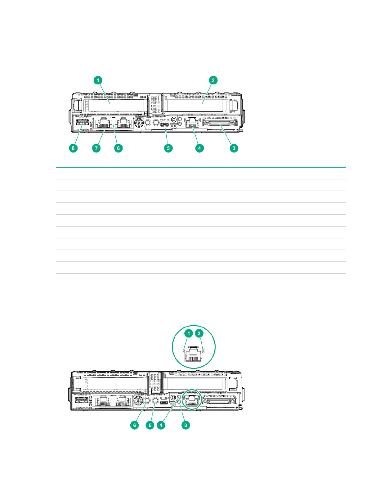
Rear panel components
Item Description
1 Slot 1 PCIe3 x16 (16, 8, 4, 1)
2 Slot 2 PCIe3 x16 (16, 8, 4, 1) or FlexibleLOM
3 SUV connector
4 iLO Management Port
1
5 iLO Service Port
6 Media Module (optional - NIC ports)
7 Server serial number and iLO label pull tab
8 USB 3.0 port
1
If the RCM module is installed on the chassis, the iLO Management Port will be automatically disabled. For more
information, see the chassis user guide.
Rear panel LEDs and buttons
6 Component identification

Item Description Status
1 NIC link LED
1
Green = Linked to network
Off = No network connection
2 NIC activity LED
3 Health LED
1
1
4 Do not remove LED
5 UID button/LED
1
Green or flashing green = Network activity
Off = No network activity
Solid green = Normal
Flashing green = iLO rebooting
Flashing amber = System degraded
Flashing red = System critical
1
Flashing white = Do not remove the server.
Removing the server may terminate the current
operation and cause data loss.
Off = The server can be removed.
Solid blue = Activated
• 1 flash per second = Remote management
or firmware upgrade in progress
• 4 flashes per second = iLO manual soft
reboot sequence initiated
• 8 flashes per second = iLO manual hard
reboot sequence in progress
6 Power button/LED
1
If the health LED indicates a degraded or critical state, review the system IML or use iLO to review the system health
status.
2
When the LEDs described in this table flash simultaneously, a power fault has occurred. For more information, see
"Power fault LEDs."
3
Facility power is not present, power cord is not attached, no power supplies are installed, power supply failure has
occurred, or the front I/O cable is disconnected.
Power fault LEDs
The following table provides a list of power fault LEDs, and the subsystems that are affected. Not all
power faults are used by all servers.
Off = Deactivated
2
Solid green = System on
Flashing green = Performing power on
sequence
Solid amber = System in standby
Off = No power present
3
Power fault LEDs 7
Subsystem LED behavior
System board 1 flash
Processor 2 flashes
Memory 3 flashes
Riser board PCIe slots 4 flashes
FlexibleLOM 5 flashes
Removable HPE Flexible Smart Array
controller
System board PCIe slots 7 flashes
Power backplane or storage backplane 8 flashes
Power supply 9 flashes
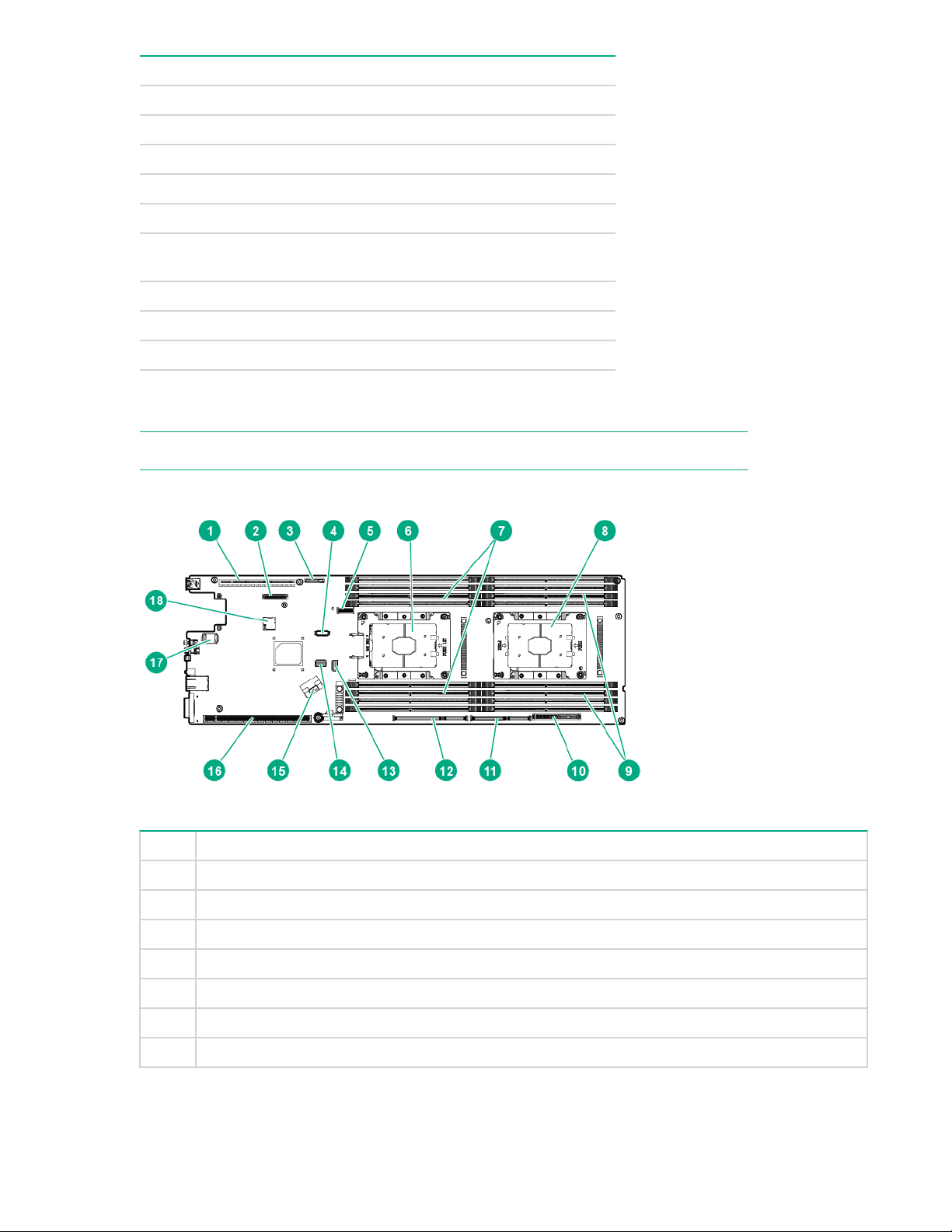
System board components
NOTE: HPE ProLiant XL170r and XL190r Gen10 Servers share the same system board.
6 flashes
Item Description
1 Primary riser slot 1
2 Media Module connector
3 System battery
4 Fabric carrier sideband signal connector
5 M.2 SSD riser connector
6 Processor 1
7 DIMMs for processor 1
8 System board components
Table Continued
Item Description
8 Processor 2
9 DIMMs for processor 2
10 Bayonet board slot
11 Secondary riser slot 4
12 Secondary riser slot 3
13 Slimline SATA x4 connector
14 System maintenance switch
15 Slimline SATA x8 connector
16 Secondary riser slot 2
17 TPM connector
18 microSD slot
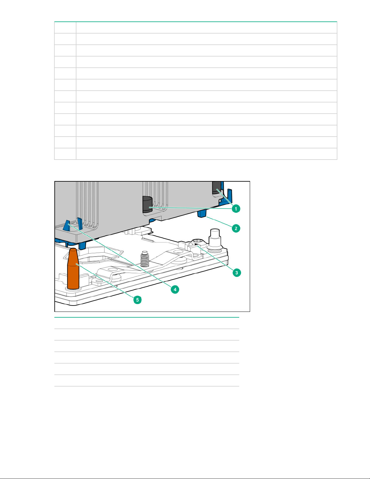
Processor, heatsink, and socket components
Item Description
1 Heatsink nuts
2 Processor frame
3 Pin 1 indicator
1
4 Heatsink latch
5 Alignment post
1
Symbol also on the processor and frame.
Processor, heatsink, and socket components 9

System maintenance switch descriptions
Position Default Function
1
S1
S2 — Reserved
S3 Off Reserved
S4 Off Reserved
1
S5
1, 2
S6
S7 — Reserved
S8 — Reserved
Off
Off
Off
Off = iLO security is enabled.
On = iLO security is disabled.
Off = Power-on password is
enabled.
On = Power-on password is
disabled.
Off = No function
On = Restore default
manufacturing settings
S9 — Reserved
S10 — Reserved
S11 — Reserved
S12 — Reserved
1
You can access the redundant ROM by setting S1, S5, and S6 to On.
2
When the system maintenance switch position 6 is set to the On position, the system is prepared to
restore all configuration settings to their manufacturing defaults.
When the system maintenance switch position 6 is set to the On position and Secure Boot is enabled,
some configurations cannot be restored. For more information, see Secure Boot configuration.
Bayonet board components
1U bayonet board
10 System maintenance switch descriptions
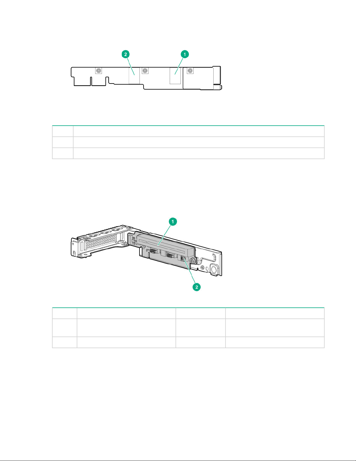
Item Description
1 Port 1
2 Port 2
PCIe riser board slot definitions
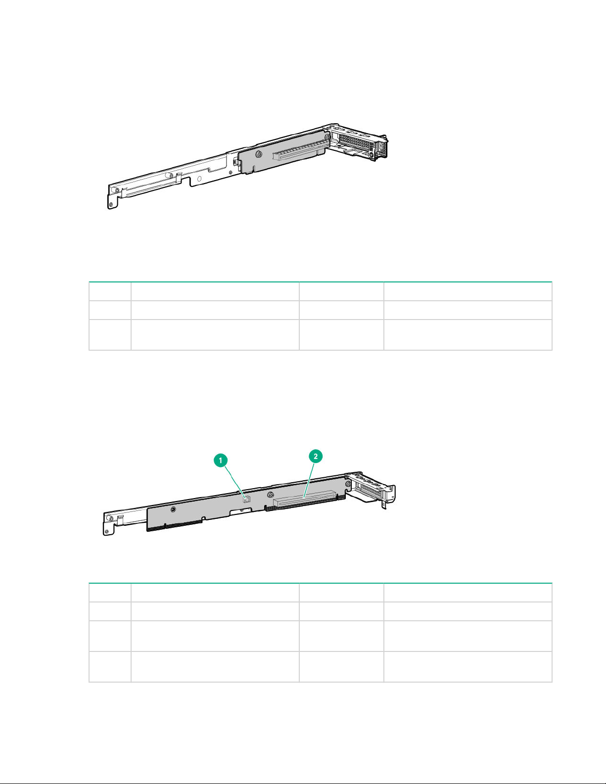
Primary riser components
Item Form Factor Slot number Description
1 Storage controller or low-profile
PCIe expansion board
2 — — Storage backup power connector
1 PCIe3 x16 (16, 8, 4, 1) for Processor
1
PCIe riser board slot definitions 11
FlexibleLOM 1U riser
Item Form Factor Slot number Description
1 FlexibleLOM FlexibleLOM slot PCIe3 x16 for Processor 1
2 Slimline SAS cable for NVMe
support
— Port 1
1
1
Not shown
1U secondary riser for processor 1
Item Form Factor Slot number Description
1 — — Storage backup power connector
2 Storage controller or low-profile
PCIe expansion board
3 Slimline SAS cable for NVMe
support
2 PCIe3 x16 (16, 8, 4, 1) for Processor
1
— Port 1
1
12 FlexibleLOM 1U riser
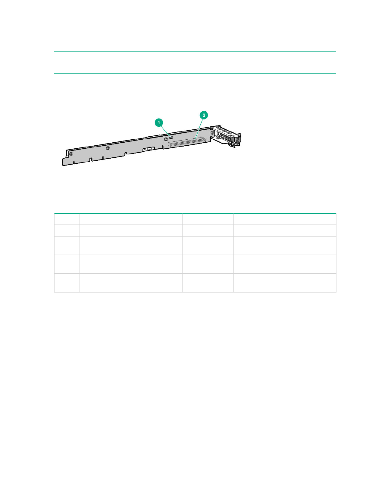
1
Not shown
1U secondary riser for processor 2
NOTE: The HPE XL170r 16NVMe Gen10 P2 LP Riser Kit (PN 874304-B21) is only for use in servers that
are installed in the HPE Apollo r2800 Gen10 Chassis with 16 NVMe. For more information, see Cabling.
Item Form Factor Slot number Description
1 — — Storage backup power connector
2 Storage controller or low-profile
PCIe expansion board
3 Slimline SAS cable for NVMe
2 PCIe3 x16 (16, 8, 4, 1) for Processor
2
— Port 1
1
support
4 Slimline SAS cable for NVMe
— Port 2
1
support
1
Not shown
1U secondary riser for processor 2 13
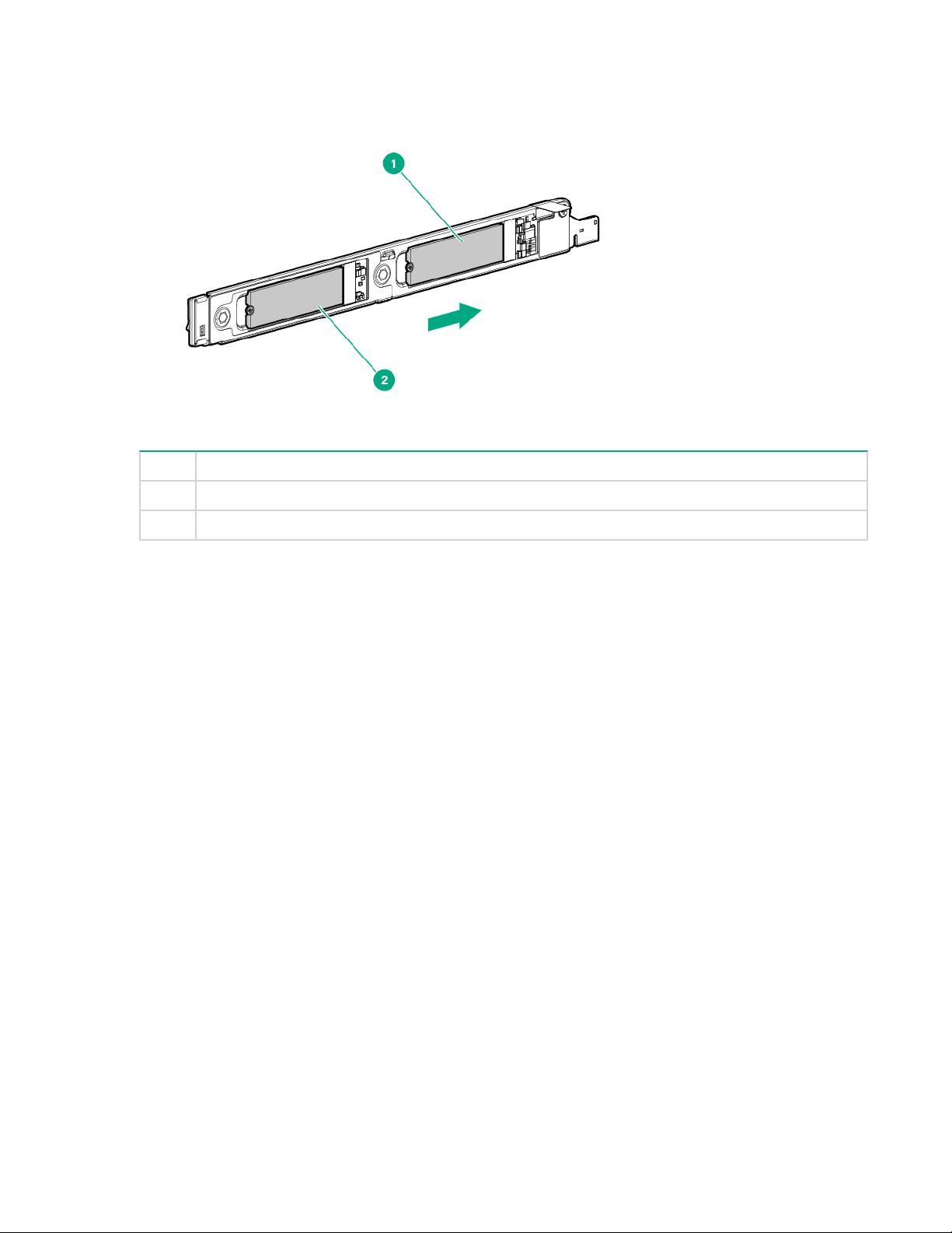
M.2 SSD riser bay numbering
Item Description
1 Bay 7
2 Bay 8
The arrow points toward the server tray handle.
14 M.2 SSD riser bay numbering

Setup
Optional service
Delivered by experienced, certified engineers, Hewlett Packard Enterprise support services help you keep
your servers up and running with support packages tailored specifically for HPE ProLiant systems.
Hewlett Packard Enterprise support services let you integrate both hardware and software support into a
single package. A number of service level options are available to meet your business and IT needs.
Hewlett Packard Enterprise support services offer upgraded service levels to expand the standard
product warranty with easy-to-buy, easy-to-use support packages that will help you make the most of your
server investments. Some of the Hewlett Packard Enterprise support services for hardware, software or
both are:
• Foundation Care – Keep systems running.
◦ 6-Hour Call-to-Repair
◦ 4-Hour 24x7
◦ Next Business Day
• Proactive Care – Help prevent service incidents and get you to technical experts when there is one.
◦ 6-Hour Call-to-Repair
◦ 4-Hour 24x7
◦ Next Business Day
• Deployment service for both hardware and software
• Hewlett Packard Enterprise Education Services – Help train your IT staff.
1
The time commitment for this repair service might vary depending on the site's geographical region. For
more service information available in your site, contact your local
center.
For more information on Hewlett Packard Enterprise support services, see the Hewlett Packard
Enterprise website.
1
1
Hewlett Packard Enterprise support
Setup 15
Server warnings and cautions
WARNING: This server is heavy. To reduce the risk of personal injury or damage to the equipment:
• Observe local occupational health and safety requirements and guidelines for manual material
handling.
• Get help to lift and stabilize the product during installation or removal, especially when the
product is not fastened to the rails. Hewlett Packard Enterprise recommends that a minimum of
two people are required for all rack server installations. A third person may be required to help
align the server if the server is installed higher than chest level.
• Use caution when installing the server in or removing the server from the rack; it is unstable
when not fastened to the rails.
WARNING: To reduce the risk of personal injury from hot surfaces, allow the drives and the internal
system components to cool before touching them.
WARNING: To reduce the risk of personal injury, electric shock, or damage to the equipment,
remove the power cord to remove power from the server. Pressing the Power On/Standby button
does not shut off system power completely. Portions of the power supply and some internal circuitry
remain active until AC power is removed.
CAUTION: Protect the server from power fluctuations and temporary interruptions with a regulating
uninterruptible power supply. This device protects the hardware from damage caused by power
surges and voltage spikes and keeps the system in operation during a power failure.
CAUTION: Do not operate the server for long periods with the access panel open or removed.
Operating the server in this manner results in improper airflow and improper cooling that can lead to
thermal damage.
Server shipping carton contents
Unpack the server shipping carton and locate the materials and documentation necessary for installing
the server. All the rack mounting hardware necessary for installing the server into the rack is included with
the rack or the server.
The contents of the server shipping carton include:
• Server
• Printed setup documentation
• Accessory kit
Installation overview
Installation of a server requires the following steps:
1. Install the chassis into the rack.
2. Install any server options.
16 Server warnings and cautions
3. Install the server into the chassis.
4. Install the operating system.
5. Register the product.
Installing the chassis into the rack
To install the chassis into the rack, see the HPE Apollo 2000 Gen10 Chassis User Guide on the Hewlett
Packard Enterprise website.
Installing hardware options
Before installing and initializing the server, install any hardware options. For options installation
information, see the documentation that ships with the option. For server-specific information, see
Hardware options installation."
"
Installing the operating system
To operate properly, the server must have a supported operating system installed. For the latest
information on operating system support, see the Hewlett Packard Enterprise website (http://
www.hpe.com/info/supportos).
IMPORTANT: HPE ProLiant XL servers do not support operating system installation with Intelligent
Provisioning, but they do support the maintenance features. For more information, see "Performing
Maintenance" in the HPE Intelligent Provisioning User Guide and online help.
To install an operating system on the server, use one of the following methods:
• Insert the operating system CD into the USB-attached DVD-ROM drive (user provided) and reboot the
server. Download the Service Pack for ProLiant from the SPP download site (http://www.hpe.com/
servers/spp/download) and create SPP media to install the drivers.
• Remote deployment installation — Use PXE boot into a server and deploy an operating system with a
host server.
For additional system software and firmware updates, download the Service Pack for ProLiant from the
Hewlett Packard Enterprise website (http://www.hpe.com/servers/spp/download). Software and
firmware must be updated before using the node for the first time, unless any installed software or
components require an older version.
For more information on using these installation methods, see the Hewlett Packard Enterprise website
(http://www.hpe.com/info/ilo).
Selecting boot options
This server supports both Legacy BIOS Boot Mode and UEFI Boot Mode. On servers operating in UEFI
Boot Mode, the boot controller and boot order are set automatically.
Procedure
1. Press the Power On/Standby button.
2. Do one of the following:
Installing the chassis into the rack 17

a. To enter the UEFI System Utilities screen and modify the server configuration ROM default
settings, press the F9 key on the ProLiant POST screen. Choose one of the following boot modes:
• Legacy BIOS
• UEFI (default)
b. If you do not need to modify the server configuration and are ready to install the system software,
press the F10 key to access Intelligent Provisioning.
For more information on automatic configuration, see the UEFI documentation on the Hewlett Packard
Enterprise website.
Registering the server
To experience quicker service and more efficient support, register the product at the Hewlett Packard
Enterprise Product Registration website.
18 Registering the server
Operations
This chapter describes the hardware operations carried out prior to and after installing or removing a
hardware option, or performing a server maintenance or troubleshooting procedure.
Before performing these hardware operations, review and observe the server warnings and cautions.
Powering up the server
The SL/XL Chassis Firmware initiates an automatic power-up sequence when the servers are installed. If
the default setting is changed, use one of the following methods to power up each server:
• Use a virtual power button selection through iLO.
• Press and release the Power On/Standby button.
When the server goes from the standby mode to the full power mode, the server power LED changes
from amber to green.
For more information about iLO, see the
Power down the server
Before powering down the server for any upgrade or maintenance procedures, perform a backup of
critical server data and programs.
IMPORTANT: When the server is in standby mode, auxiliary power is still being provided to the
system.
To power down the server, use one of the following methods:
• Press and release the Power On/Standby button.
This method initiates a controlled shutdown of applications and the OS before the server enters
standby mode.
• Press and hold the Power On/Standby button for more than 4 seconds to force the server to enter
standby mode.
This method forces the server to enter standby mode without properly exiting applications and the OS.
If an application stops responding, you can use this method to force a shutdown.
• Use a virtual power button selection through iLO.
This method initiates a controlled remote shutdown of applications and the OS before the server
enters standby mode.
Hewlett Packard Enterprise website.
Before proceeding, verify that the server is in standby mode by observing that the system power LED is
amber.
Removing the server tray blank
CAUTION: To ensure proper thermal cooling, all server tray slots must be populated with servers or
server tray blanks.
Operations 19
Procedure
Remove the server tray blank.
Installing the server tray blank
CAUTION: To ensure proper thermal cooling, all server tray slots must be populated with servers or
server tray blanks.
Procedure
Install the server tray blank.
20 Installing the server tray blank
Removing the server from the chassis
CAUTION: Before powering down the server, perform a backup of critical server data and
programs. Removing the server while the Do not remove LED is on may result in data loss or
corruption.
CAUTION: To avoid damage to the server, always support the bottom of the server when removing
it from the chassis.
CAUTION: To ensure proper thermal cooling, all server tray slots must be populated with servers or
server tray blanks.
Procedure
1. Back up all server data.
2. Power down the server.
3. Disconnect all peripheral cables from the server.
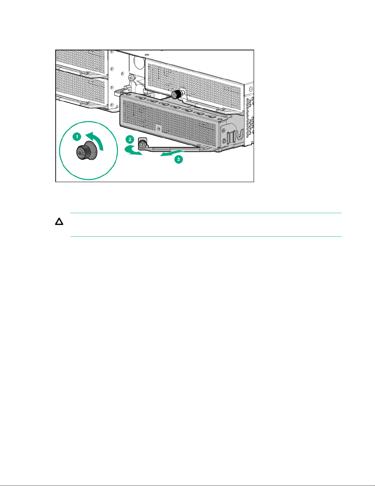
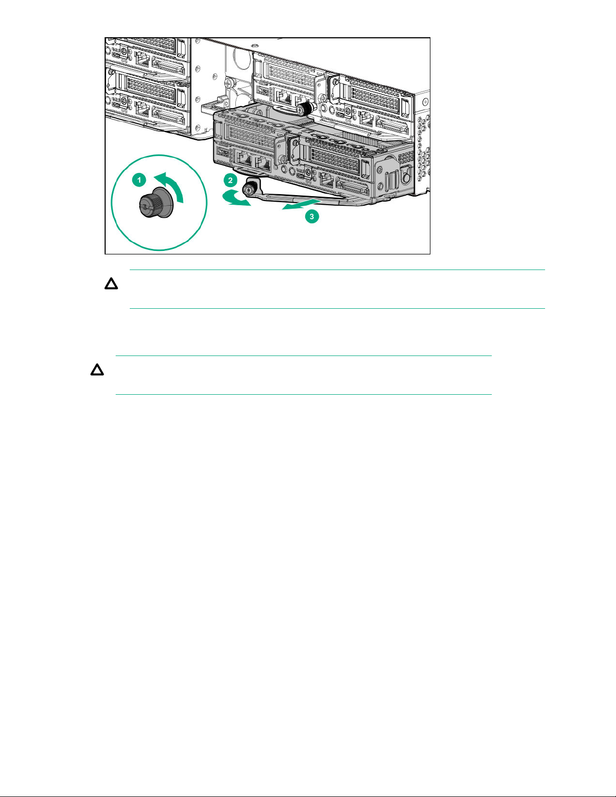
4. Remove the server from the chassis:
a. Loosen the thumbscrew.
b. Open the locking lever.
c. Slide out the server.
Removing the server from the chassis 21
CAUTION: To avoid damage to the device, do not use the removal handle to carry the server.
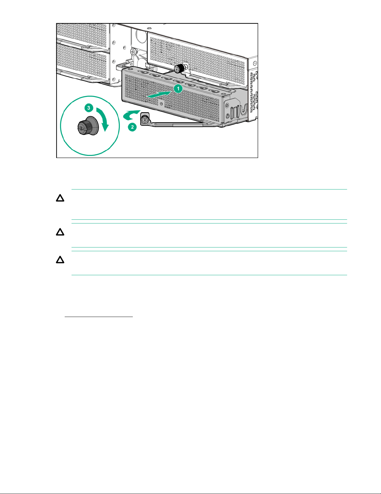
Installing the server into the chassis
CAUTION: To avoid damage to the device, do not use the removal handle to carry it.
Procedure
1. Install the server into the chassis:
a. Slide the server into the chassis.
b. Close the locking lever.
c. Tighten the thumbscrew.
22 Installing the server into the chassis

2. Connect all peripheral cables to the server.
3. Power up the server.
Removing the air baffle
Procedure
1. Back up all server data.
2. Power down the server.
3. Remove the server from the chassis.
4. Remove the air baffle.
Installing the air baffle
CAUTION: To prevent damage to the server, ensure that all DIMM latches are in closed and locked
position before installing the air baffle.
Removing the air baffle 23

Procedure
1. Install the air baffle.
2. Install the server into the chassis.
3. Power up the server.
Removing the bayonet board
Procedure
1. Back up all server data.
2. Power down the server.
3. Remove the server from the chassis.
4. Remove the air baffle.
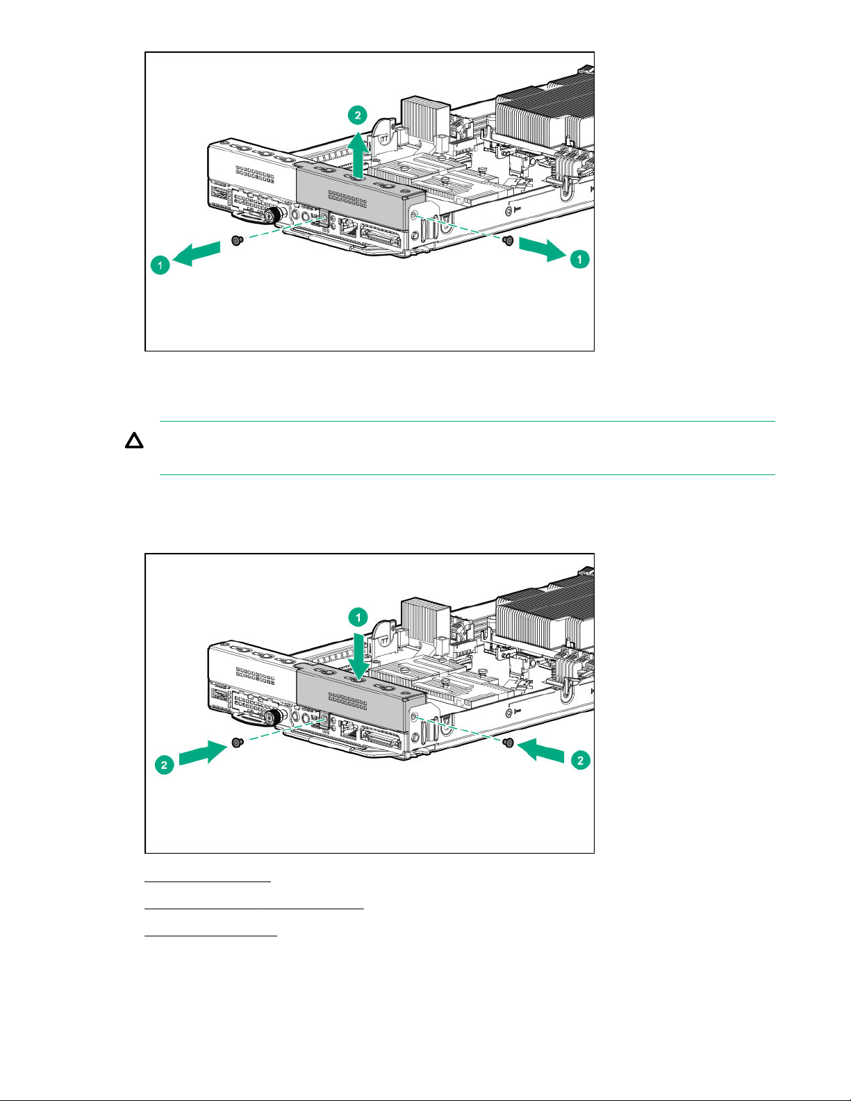
5. Remove the bayonet board.
a. Remove the top three screws from the cover.
b. Remove the bottom three screws from the cover and lift the cover up.
24 Removing the bayonet board
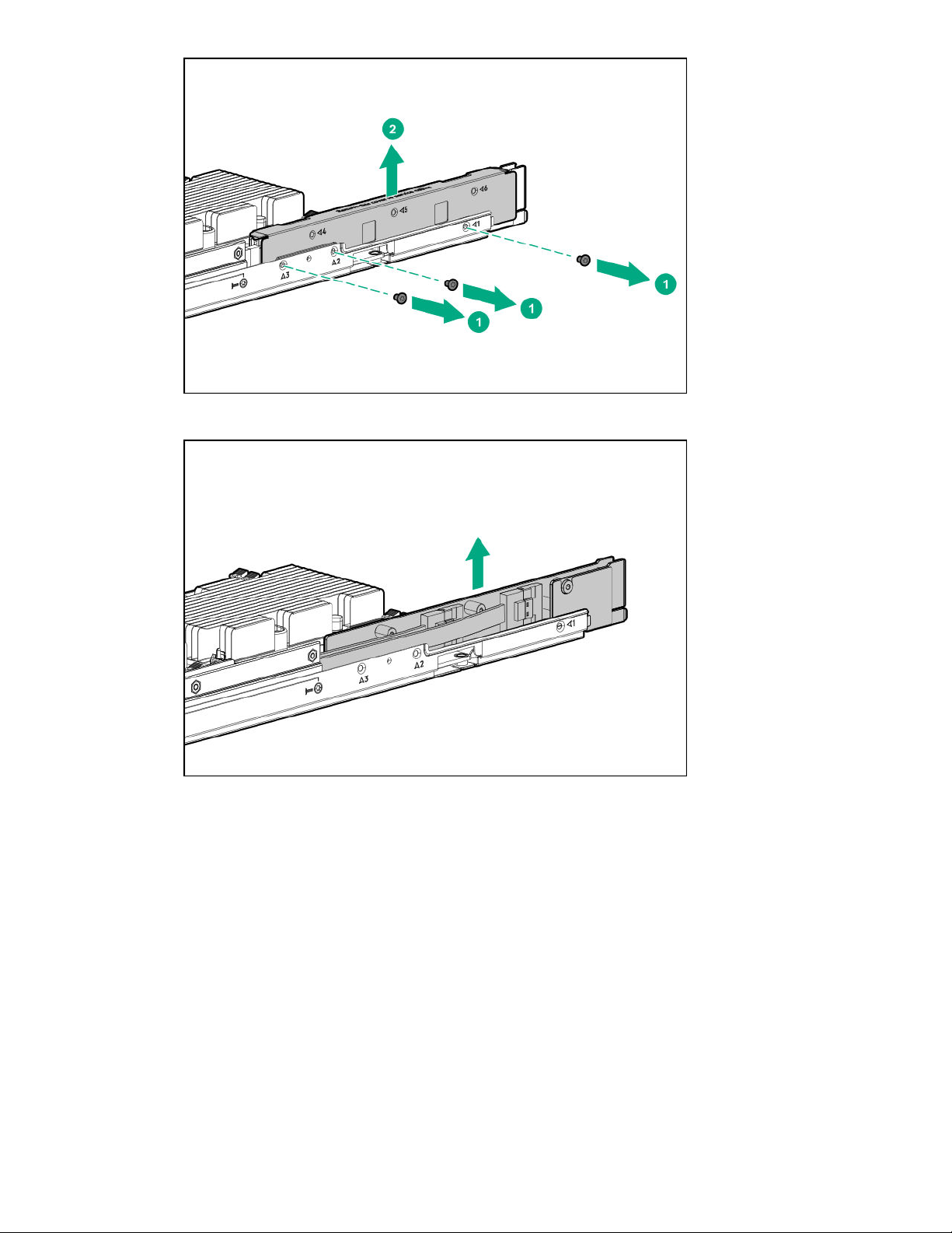
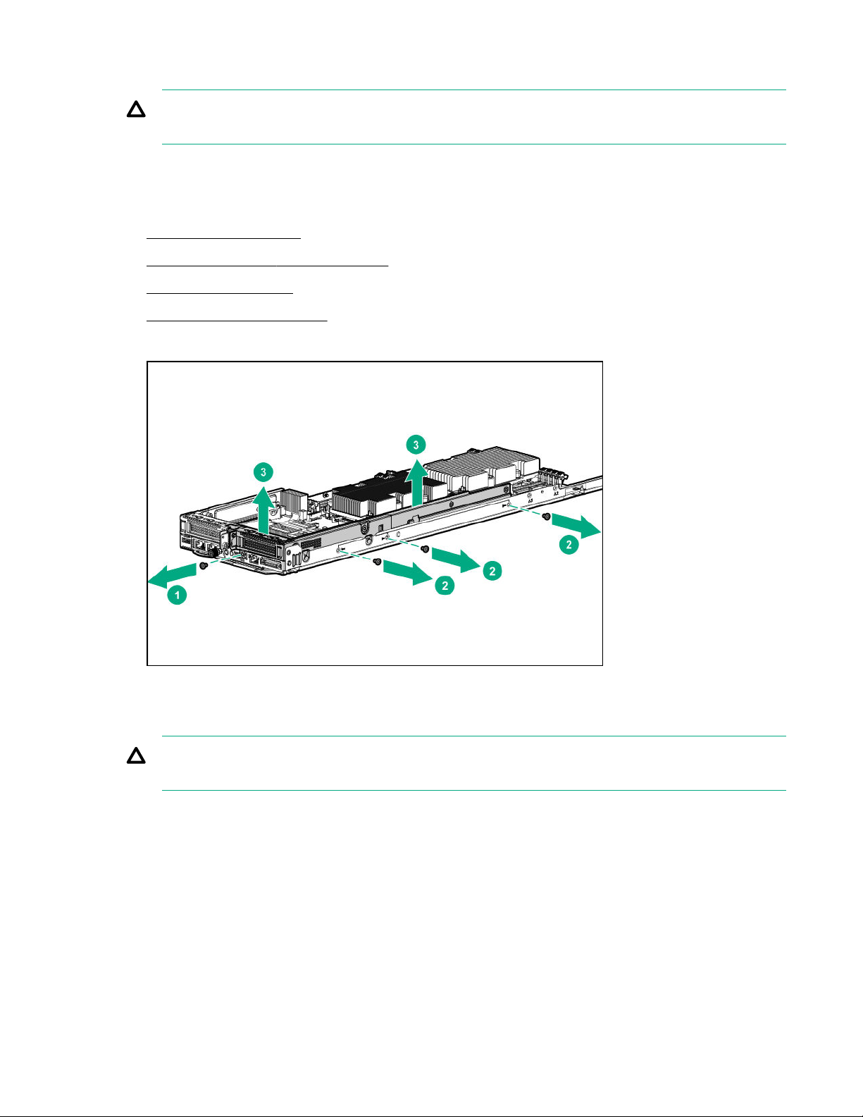
c. Gently lift up the bayonet board and disconnect the cables.
Installing the bayonet board
Procedure
1. Install the bayonet board.
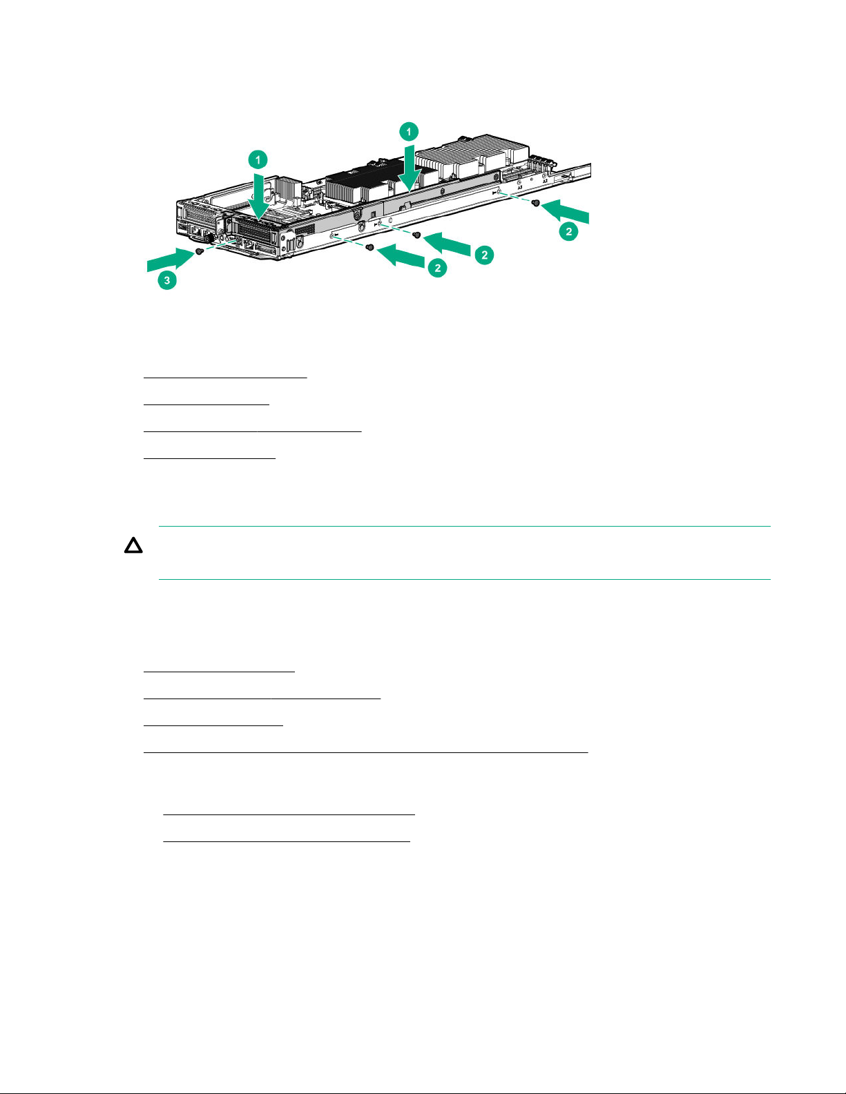
a. Connect all cables and firmly seat the bayonet board.
Installing the bayonet board 25
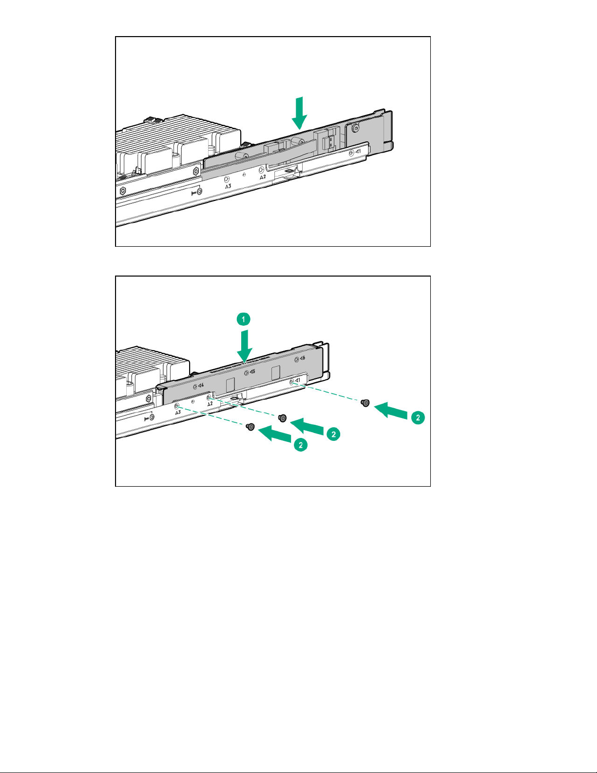
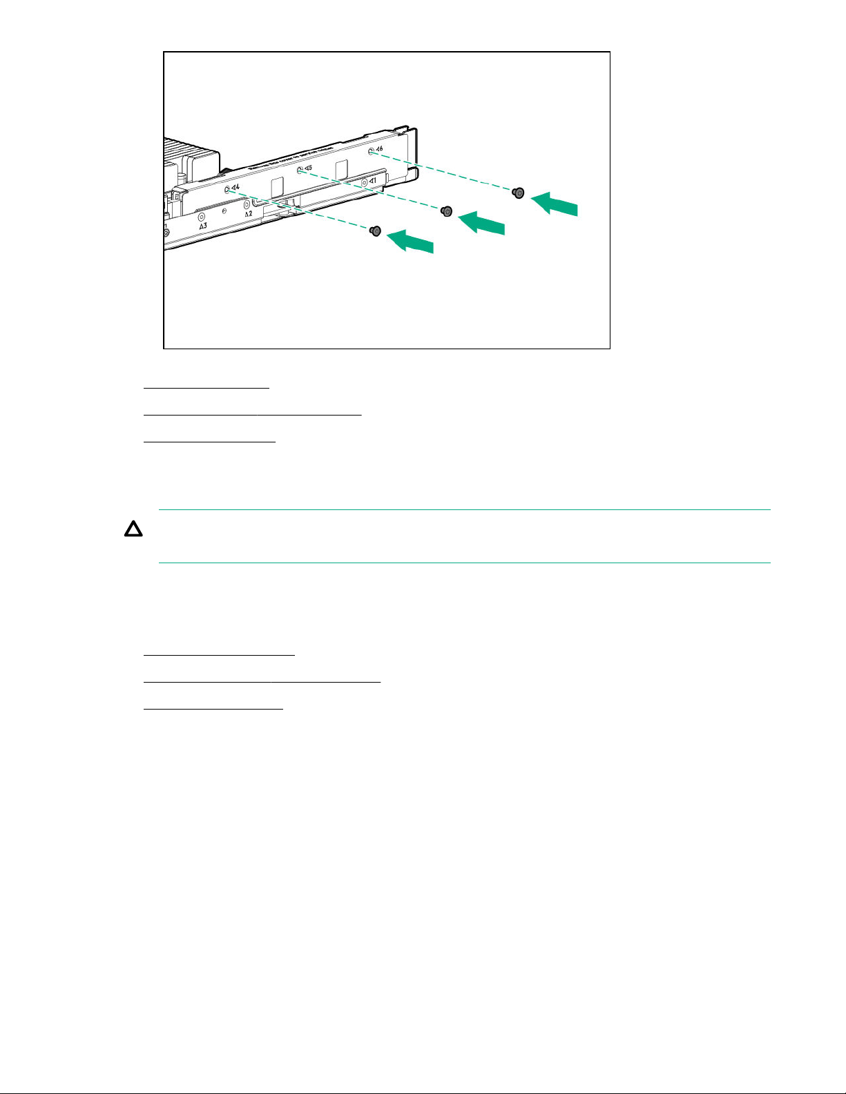
b. Install the cover and the bottom three screws.
c. Install the top three screws.
26 Operations
2. Install the air baffle.
3. Install the server into the chassis.
4. Power up the server.
Removing the secondary PCI riser blank
CAUTION: To prevent improper cooling and thermal damage, do not operate the server unless
either riser blanks or riser cages are installed.
Procedure
1. Back up all server data.
2. Power down the server.
3. Remove the server from the chassis.
4. Remove the air baffle.
5. Remove the secondary PCI riser blank.
Removing the secondary PCI riser blank 27
Installing the secondary PCI riser blank
CAUTION: To prevent improper cooling and thermal damage, do not operate the server unless
either riser blanks or riser cages are installed.
Procedure
1. Install the secondary PCI riser blank.
2. Install the air baffle.
3. Install the server into the chassis.
4. Power up the server.
28 Installing the secondary PCI riser blank
Removing the secondary PCI riser cage
CAUTION: To prevent improper cooling and thermal damage, do not operate the server unless
either riser blanks or riser cages are installed.
Procedure
1. Back up all server data.
2. Power down the server.
3. Remove the server from the chassis.
4. Remove the air baffle.
5. Remove the bayonet board.
6. Remove the secondary PCI riser cage.
Installing the secondary PCI riser cage
CAUTION: To prevent improper cooling and thermal damage, do not operate the server unless all
PCI slots have either an expansion slot cover or an expansion board installed.
Procedure
1. Install the secondary PCI riser cage. Ensure that the riser board is firmly seated in the connectors on
the system board.
Removing the secondary PCI riser cage 29
2. Install the bayonet board.
3. Install the air baffle.
4. Install the server into the chassis.
5. Power up the server.
Removing the primary PCI riser cage
CAUTION: To prevent improper cooling and thermal damage, do not operate the server unless
either riser blanks or riser cages are installed.
Procedure
1. Back up all server data.
2. Power down the server.
3. Remove the server from the chassis.
4. Remove the air baffle.
5. If a secondary PCI riser cage is installed, remove the bayonet board.
6. Do one of the following:
• Remove the secondary PCI riser blank.
• Remove the secondary PCI riser cage.
7. Remove the primary PCI riser cage.
30 Removing the primary PCI riser cage
 Loading...