

Page 1

HP ProLiant WS460c Gen8 Graphics Server
Part Number: 703968-004
Blade and Expansion Blade
User Guide
Abstract
This guide provides operation information for the HP ProLiant WS460c Gen8 Graphics Server Blade and Expansion Blade. This guide is for
technicians that install, administer, and troubleshoot servers and storage systems.
February 2014
Edition: 4
Page 2

© Copyright 2012, 2014 Hewlett-Packard Development Company, L.P.
The information contained herein is subject to change without notice. The only warranties for HP products and services are set forth in the express
warranty statements accompanying such products and services. Nothing herein should be construed as constituting an additional warranty. HP shall
not be liable for technical or editorial errors or omissions contained herein.
Microsoft®, Windows®, and Windows Server® are U.S. registered trademarks of Microsoft Corporation.
Page 3

Contents
Component identification ............................................................................................................... 6
Front panel components ............................................................................................................................. 6
Front panel components for workstation blade with graphics expansion blade .................................................. 7
Front panel LEDs and buttons ...................................................................................................................... 7
Front panel LEDs and buttons for workstation blade with graphics expansion blade ........................................... 8
Hot-plug drive LED definitions ...................................................................................................................... 9
System board components ........................................................................................................................ 10
System maintenance switch ............................................................................................................. 11
Mezzanine connector definitions ..................................................................................................... 11
DIMM slot locations ....................................................................................................................... 11
DIMM tool location ........................................................................................................................ 12
HP c-Class Blade SUV Cable..................................................................................................................... 12
Operations ................................................................................................................................. 14
Power up the workstation blade ................................................................................................................ 14
Power down the workstation blade ............................................................................................................ 14
Remove the workstation blade ................................................................................................................... 15
Remove the access panel.......................................................................................................................... 16
Install the access panel............................................................................................................................. 16
Remove the front panel/hard drive cage assembly ...................................................................................... 16
Remove the DIMM baffle .......................................................................................................................... 17
Remove the SAS controller ........................................................................................................................ 18
Install the SAS controller ........................................................................................................................... 19
Remove the WS460c Graphics Expansion Blade access panel ..................................................................... 20
Remove the WS460c Graphics Expansion Blade ........................................................................................ 21
Remove the WS460c Graphics Expansion Blade PCIe card cage .................................................................. 23
Install the NVIDIA Quadro K4000 graphics card ........................................................................................ 26
Install the NVIDIA Quadro K5000 or K6000 graphics card .......................................................................... 28
Install the NVIDIA GRID K1 or GRID K2 I/O Plate ....................................................................................... 28
Install the NVIDIA GRID K1 or K2 graphics card ......................................................................................... 32
Install the NVIDIA Tesla K20 or Tesla K20X I/O Plate .................................................................................. 32
Install the NVIDIA Tesla K20 or K20X graphics card .................................................................................... 35
Setup ......................................................................................................................................... 37
Overview ............................................................................................................................................... 37
Installing an HP BladeSystem c-Class enclosure ........................................................................................... 37
Installing server blade options ................................................................................................................... 37
Installing interconnect modules .................................................................................................................. 37
Interconnect bay numbering and device mapping .............................................................................. 38
Connecting to the network ........................................................................................................................ 39
Installing a server blade ........................................................................................................................... 40
Completing the configuration .................................................................................................................... 41
Hardware options installation ....................................................................................................... 42
Introduction ............................................................................................................................................ 42
Drive option ........................................................................................................................................... 42
Processor option ...................................................................................................................................... 43
Contents 3
Page 4

Memory options ...................................................................................................................................... 47
HP SmartMemory .......................................................................................................................... 48
Memory subsystem architecture ....................................................................................................... 48
Single-, dual-, and quad-rank DIMMs ............................................................................................... 49
DIMM identification ....................................................................................................................... 50
Memory configurations ................................................................................................................... 50
General DIMM slot population guidelines ......................................................................................... 52
Installing a DIMM .......................................................................................................................... 53
Mezzanine card option ............................................................................................................................ 54
NVIDIA Quadro 1000M and 3000M mezzanine cards ............................................................................... 56
FBWC capacitor pack ............................................................................................................................. 58
HP Trusted Platform Module option ............................................................................................................ 60
Installing the Trusted Platform Module board ..................................................................................... 61
Retaining the recovery key/password .............................................................................................. 62
Enabling the Trusted Platform Module ............................................................................................... 63
Cabling ..................................................................................................................................... 64
Cabling resources ................................................................................................................................... 64
FBWC capacitor pack cabling .................................................................................................................. 64
Using the HP c-Class Blade SUV Cable ...................................................................................................... 64
Connecting locally to a server blade with video and USB devices .................................................................. 65
Accessing a server blade with local KVM ......................................................................................... 65
Accessing local media devices ........................................................................................................ 66
Troubleshooting .......................................................................................................................... 67
Troubleshooting resources ........................................................................................................................ 67
Software and configuration utilities ............................................................................................... 68
Server mode ........................................................................................................................................... 68
HP product QuickSpecs ............................................................................................................................ 68
HP iLO Management ............................................................................................................................... 68
HP iLO ......................................................................................................................................... 68
Intelligent Provisioning .................................................................................................................... 70
Scripting Toolkit for Windows and Linux ........................................................................................... 72
HP Service Pack for ProLiant ..................................................................................................................... 72
HP Smart Update Manager ............................................................................................................. 72
HP ROM-Based Setup Utility ..................................................................................................................... 72
Using RBSU .................................................................................................................................. 73
Auto-configuration process .............................................................................................................. 73
Boot options ................................................................................................................................. 74
Configuring AMP modes ................................................................................................................ 74
Re-entering the server serial number and product ID ........................................................................... 74
Utilities and features ................................................................................................................................ 75
Array Configuration Utility .............................................................................................................. 75
Option ROM Configuration for Arrays ............................................................................................. 76
ROMPaq utility .............................................................................................................................. 76
Automatic Server Recovery ............................................................................................................. 76
USB support .................................................................................................................................. 77
Redundant ROM support ................................................................................................................ 77
Keeping the system current ....................................................................................................................... 77
Drivers ......................................................................................................................................... 77
Software and firmware ................................................................................................................... 78
Version control .............................................................................................................................. 78
HP operating systems and virtualization software support for ProLiant servers ........................................ 78
Contents 4
Page 5

HP Technology Service Portfolio ...................................................................................................... 78
Change control and proactive notification ........................................................................................ 79
Battery replacement .................................................................................................................... 80
Regulatory information ................................................................................................................ 81
Safety and regulatory compliance ............................................................................................................. 81
Turkey RoHS material content declaration ................................................................................................... 81
Ukraine RoHS material content declaration ................................................................................................. 81
Warranty information .............................................................................................................................. 81
Electrostatic discharge ................................................................................................................. 82
Preventing electrostatic discharge .............................................................................................................. 82
Grounding methods to prevent electrostatic discharge .................................................................................. 82
Specifications ............................................................................................................................. 83
Environmental specifications ..................................................................................................................... 83
Server blade specifications ....................................................................................................................... 83
Support and other resources ........................................................................................................ 84
Before you contact HP .............................................................................................................................. 84
HP contact information ............................................................................................................................. 84
Customer Self Repair ............................................................................................................................... 84
Acronyms and abbreviations ........................................................................................................ 92
Documentation feedback ............................................................................................................. 94
Index ......................................................................................................................................... 95
Contents 5
Page 6

Component identification
Front panel components
Item Description
1
2
3
4
5
6
*The SUV connector and the HP c-Class Blade SUV Cable are used for some workstation blade configuration and
diagnostic procedures.
Hard drive bay 1
Server blade release button
Server blade release lever
Hard drive bay 2
HP c-Class Blade SUV connector* (behind the serial label pull
tab)
Serial label pull tab
Component identification 6
Page 7

Front panel components for workstation blade with
Drive bay 2
graphics expansion blade
Item Description
1
2
3
4
5
6
* The SUV connector and the HP c-Class SUV Cable are used for some server blade configuration and diagnostic
procedures.
Serial label pull tab
HP c-Class Blade SUV connector* (behind the serial label pull
tab)
Drive bay 1
Server blade release lever
Server blade release button
Front panel LEDs and buttons
Item Description Status
Health status LED Solid Green = Normal (System is powered on)
1
Component identification 7
Page 8

Power On/Standby
Solid Green = System is powered on.
Item Description Status
bar Flashing Green = Power On/Standby button service is being initialized
Flashing Amber = Degraded condition
Flashing Red = Critical condition
Off = Normal (System is in standby)
2
button and system
power LED
UID LED Solid Blue = Identified
3
FlexibleLOM LED Green = Network linked
4
Flashing Green = System is waiting to power on; Power On/Standby button is
pressed.
Solid Amber = System is in standby; Power On/Standby button service is
initialized.
Off and the Health Status LED bar is off = The system has no power.
Off and the Health Status LED bar is flashing green = The Power On/Standby
button service is being initialized.
Flashing Blue = Active remote management
Off = No active remote management
Flashing Green = Network activity
Off = No link or activity
Front panel LEDs and buttons for workstation blade with graphics expansion blade
Item Description Status
Health status LED
1
bar
Power On/Standby
2
button and system
Solid Green = Normal (System is powered on.)
Flashing Green = Power On/Standby button service is being initialized.
Flashing Amber = Degraded condition
Flashing Red = Critical condition
Off = Normal (System is in standby.)
Solid Green = System is powered on.
Flashing Green = System is waiting to power on; Power On/Standby button is
Component identification 8
Page 9
Item Description Status
power LED pressed.
Solid Amber = System is in standby; Power On/Standby button service is
initialized.
Off and the Health Status LED bar is off = The system has no power.
Off and the Health Status LED bar is flashing green = The Power On/Standby
button service is being initialized.
UID LED Solid Blue = Identified
3
FlexibleLOM LED Green = Network linked
4
UID LED Solid Blue = Identified
5
Health status LED
6
bar
Flashing Blue = Active remote management
Off = No active remote management
Flashing Green = Network activity
Off = No link or activity
Flashing Blue = Active remote management
Off = No active remote management
Solid Green = Normal (System is powered on.)
Flashing Green = Power On/Standby button service is being initialized.
Flashing Amber = Degraded condition
Flashing Red = Critical condition
Off = Normal (System is in standby.)
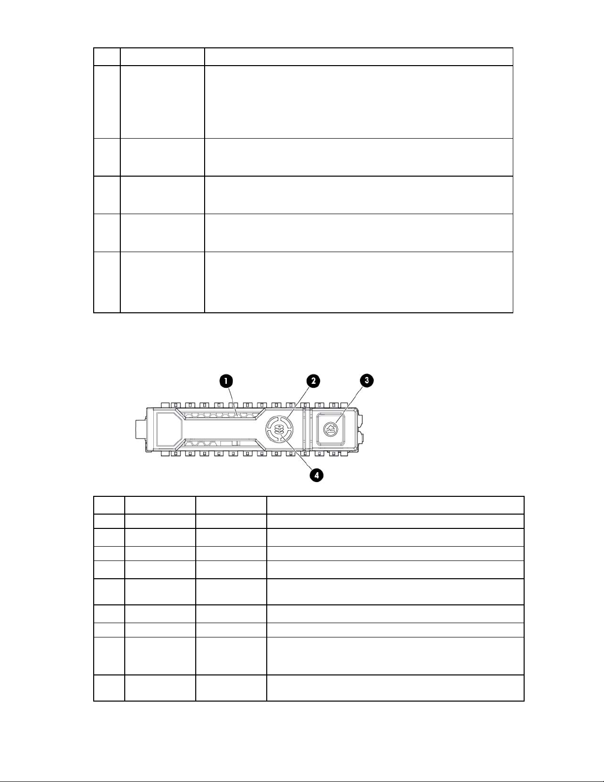
Hot-plug drive LED definitions
Item LED Status Definition
1
2
3
4
Locate Solid blue The drive is being identified by a host application.
Flashing blue The drive carrier firmware is being updated or requires an update.
Activity ring Rotating green Drive activity
Off No drive activity
Do not remove Solid white Do not remove the drive. Removing the drive causes one or more of
the logical drives to fail.
Off Removing the drive does not cause a logical drive to fail.
Drive status Solid green The drive is a member of one or more logical drives.
Flashing green The drive is rebuilding or performing a RAID migration, strip size
migration, capacity expansion, or logical drive extension, or is
erasing.
Flashing
amber/green
The drive is a member of one or more logical drives and predicts
the drive will fail.
Component identification 9
Page 10

Item LED Status Definition
Flashing amber The drive is not configured and predicts the drive will fail.
Solid amber The drive has failed.
Off The drive is not configured by a RAID controller.
System board components
Item Description
1
2
3
4
5
6
7
8
9
10
11
12
13
14
15
16
The symbols correspond to the symbols located on the interconnect bays. For more information, see the
HP ProLiant WS460c Gen8 Graphics Server Blade and Expansion Blade Installation Instructions on the HP website
(http://www.hp.com/support).
HP c-Class Blade SUV Cable connector
System battery
Processor socket 2
Processor 2 DIMM slots (8)
Processor 1 DIMM slots (8)
SAS controller connector
Processor socket 1 (populated)
Accelerator cache connector
Mezzanine connector 1 (Type A mezzanine only)
Mezzanine connector 2 (Type A or Type B mezzanine)
Enclosure connector
MicroSD card slot
FlexibleLOM connectors (2)
Internal USB connector
System maintenance switch
TPM connector
Component identification 10
 Loading...