

HP ProLiant SL250s G8 User Manual

HP ProLiant SL250s Gen8 Server
Part Number: 666298-002
User Guide
Abstract
This document provides detailed instructions to configure and use the HP ProLiant SL250s Gen8 Server.
September 2012
Edition: 2

© Copyright 2012 Hewlett-Packard Development Company, L.P.
The information contained herein is subject to change without notice. The only warranties for HP products and services are set forth in the express
warranty statements accompanying such products and services. Nothing herein should be construed as constituting an additional warranty. HP shall
not be liable for technical or editorial errors or omissions contained herein.
Confidential computer software. Valid license from HP required for possession, use or copying. Consistent with FAR 12.211 and 12.212,
Commercial Computer Software, Computer Software Documentation, and Technical Data for Commercial Items are licensed to the U.S. Government
under vendor’s standard commercial license.
Microsoft® and Windows® are U.S. registered trademarks of Microsoft Corporation. Bluetooth® is a trademark owned by its proprietor and used
by Hewlett-Packard Company under license.

Contents
Component identification ............................................................................................................... 6
Front panel components ............................................................................................................................. 6
Front panel LEDs and buttons ...................................................................................................................... 7
Rear panel components .............................................................................................................................. 8
Rear panel LEDs and buttons ....................................................................................................................... 8
System board components .......................................................................................................................... 9
DIMM slot locations ....................................................................................................................... 10
System maintenance switch ............................................................................................................. 11
NMI header .................................................................................................................................. 12
Device numbers ...................................................................................................................................... 12
Drive LED definitions ................................................................................................................................ 13
Operations ................................................................................................................................. 15
Power up the server ................................................................................................................................. 15
Power down the node .............................................................................................................................. 15
Remove the server from the chassis ............................................................................................................ 15
Remove the processor air baffle ................................................................................................................ 16
Setup ......................................................................................................................................... 17
Optional installation services .................................................................................................................... 17
Rack planning resources........................................................................................................................... 17
Optimum environment .............................................................................................................................. 17
Space and airflow requirements ...................................................................................................... 18
Temperature requirements ............................................................................................................... 18
Power requirements ....................................................................................................................... 19
Electrical grounding requirements .................................................................................................... 19
Rack warnings ........................................................................................................................................ 19
Contents of the server shipping carton ........................................................................................................ 20
Installing the chassis ................................................................................................................................ 20
Installing options ..................................................................................................................................... 20
Installing components ............................................................................................................................... 21
Installing the server into the chassis ............................................................................................................ 21
Powering up the chassis ........................................................................................................................... 23
Configuring the chassis ............................................................................................................................ 23
Powering on and selecting boot options ..................................................................................................... 23
Installing the system software .................................................................................................................... 23
Registering the server ............................................................................................................................... 23
Hardware options installation ....................................................................................................... 24
Introduction ............................................................................................................................................ 24
Processor option ...................................................................................................................................... 24
Memory options ...................................................................................................................................... 28
HP SmartMemory .......................................................................................................................... 28
Memory subsystem architecture ....................................................................................................... 29
Single-, dual-, and quad-rank DIMMs ............................................................................................... 29
DIMM identification ....................................................................................................................... 30
Memory configurations ................................................................................................................... 30
Contents 3

General DIMM slot population guidelines ......................................................................................... 32
Installing a DIMM .......................................................................................................................... 33
Drive guidelines ...................................................................................................................................... 34
Removing the hard drive blank ........................................................................................................ 34
Installing a hot-plug SAS drive ......................................................................................................... 34
Installing SFF quick-release drive cages ............................................................................................ 35
Installing a quick-release drive ......................................................................................................... 40
Controller options .................................................................................................................................... 41
Installing the cache module ............................................................................................................. 42
Installing the FBWC capacitor pack ................................................................................................. 43
Mini-SAS cable to a controller card .................................................................................................. 45
Expansion board options .......................................................................................................................... 50
Installing an expansion board ......................................................................................................... 50
Installing a PCI riser board assembly ................................................................................................ 51
Installing a FlexibleLOM riser assembly ............................................................................................ 52
Redundant hot-plug power supply option .................................................................................................... 53
Connecting the SUV cable ........................................................................................................................ 55
HP Trusted Platform Module option ............................................................................................................ 56
Installing the Trusted Platform Module board ..................................................................................... 56
Retaining the recovery key/password .............................................................................................. 58
Enabling the Trusted Platform Module ............................................................................................... 58
Cabling ..................................................................................................................................... 59
Cabling overview .................................................................................................................................... 59
FBWC capacitor pack cabling .................................................................................................................. 59
Front GPU cabling ................................................................................................................................... 60
Software and configuration utilities ............................................................................................... 62
Server mode ........................................................................................................................................... 62
Server QuickSpecs .................................................................................................................................. 62
HP iLO Management Engine ..................................................................................................................... 62
HP iLO ......................................................................................................................................... 62
Intelligent Provisioning .................................................................................................................... 64
Scripting Toolkit ............................................................................................................................ 65
HP Service Pack for ProLiant ..................................................................................................................... 65
HP Smart Update Manager ............................................................................................................. 66
HP ROM-Based Setup Utility ..................................................................................................................... 66
Using RBSU .................................................................................................................................. 67
Auto-configuration process .............................................................................................................. 67
Boot options ................................................................................................................................. 67
Configuring AMP modes ................................................................................................................ 68
Re-entering the server serial number and product ID ........................................................................... 68
Utilities and features ................................................................................................................................ 69
Array Configuration Utility .............................................................................................................. 69
Option ROM Configuration for Arrays ............................................................................................. 70
ROMPaq utility .............................................................................................................................. 70
Automatic Server Recovery ............................................................................................................. 70
USB support .................................................................................................................................. 70
Redundant ROM support ................................................................................................................ 71
Keeping the system current ....................................................................................................................... 71
Drivers ......................................................................................................................................... 71
Software and firmware ................................................................................................................... 72
Version control .............................................................................................................................. 72
HP Operating Systems and Virtualization Software Support for ProLiant Servers ..................................... 72
Contents 4

HP Technology Service Portfolio ...................................................................................................... 73
Change control and proactive notification ........................................................................................ 73
Troubleshooting .......................................................................................................................... 74
Troubleshooting resources ........................................................................................................................ 74
System battery ............................................................................................................................ 75
Regulatory compliance notices ..................................................................................................... 76
Regulatory compliance identification numbers ............................................................................................. 76
Federal Communications Commission notice ............................................................................................... 76
FCC rating label ............................................................................................................................ 76
FCC Notice, Class A Equipment ...................................................................................................... 76
FCC Notice, Class B Equipment ...................................................................................................... 76
Declaration of conformity for products marked with the FCC logo, United States only ....................................... 77
Modifications .......................................................................................................................................... 77
Cables ................................................................................................................................................... 77
Canadian notice (Avis Canadien) .............................................................................................................. 77
European Union regulatory notice ............................................................................................................. 78
Disposal of waste equipment by users in private households in the European Union ......................................... 78
Japanese notice ...................................................................................................................................... 79
BSMI notice ............................................................................................................................................ 79
Korean notice ......................................................................................................................................... 79
Chinese notice ........................................................................................................................................ 80
Vietnam compliance marking notice .......................................................................................................... 80
Ukraine notice ........................................................................................................................................ 80
Laser compliance .................................................................................................................................... 80
Battery replacement notice ........................................................................................................................ 81
Taiwan battery recycling notice ................................................................................................................. 81
Power cord statement for Japan ................................................................................................................. 81
Acoustics statement for Germany (Geräuschemission) .................................................................................. 82
Electrostatic discharge ................................................................................................................. 83
Preventing electrostatic discharge .............................................................................................................. 83
Grounding methods to prevent electrostatic discharge .................................................................................. 83
Specifications ............................................................................................................................. 84
Environmental specifications ..................................................................................................................... 84
Server specifications ................................................................................................................................ 84
Hot-plug power supply calculations ............................................................................................................ 84
Support and other resources ........................................................................................................ 85
Before you contact HP .............................................................................................................................. 85
HP contact information ............................................................................................................................. 85
Customer Self Repair ............................................................................................................................... 85
Acronyms and abbreviations ........................................................................................................ 93
Documentation feedback ............................................................................................................. 97
Index ......................................................................................................................................... 98
Contents 5
Component identification
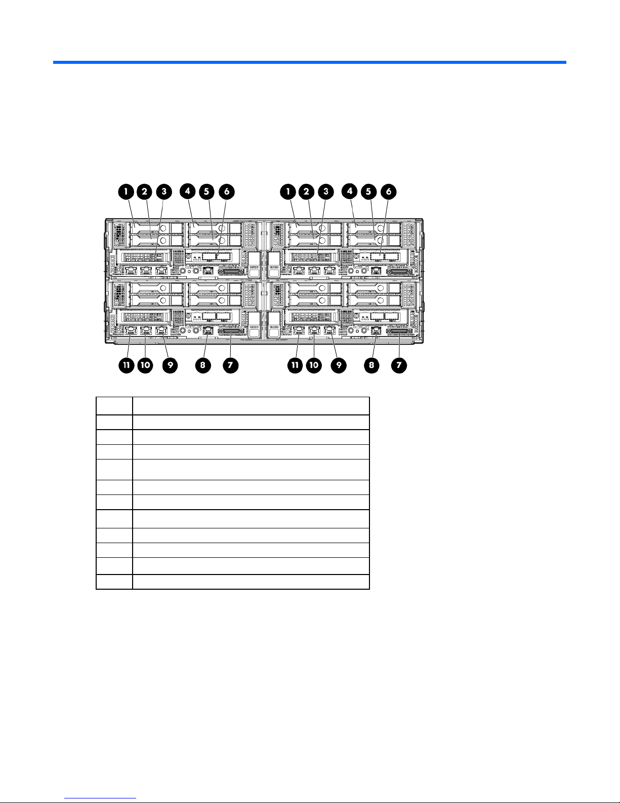
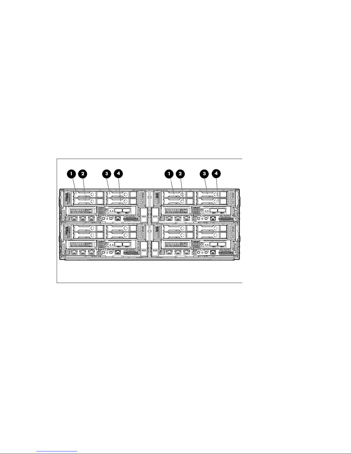
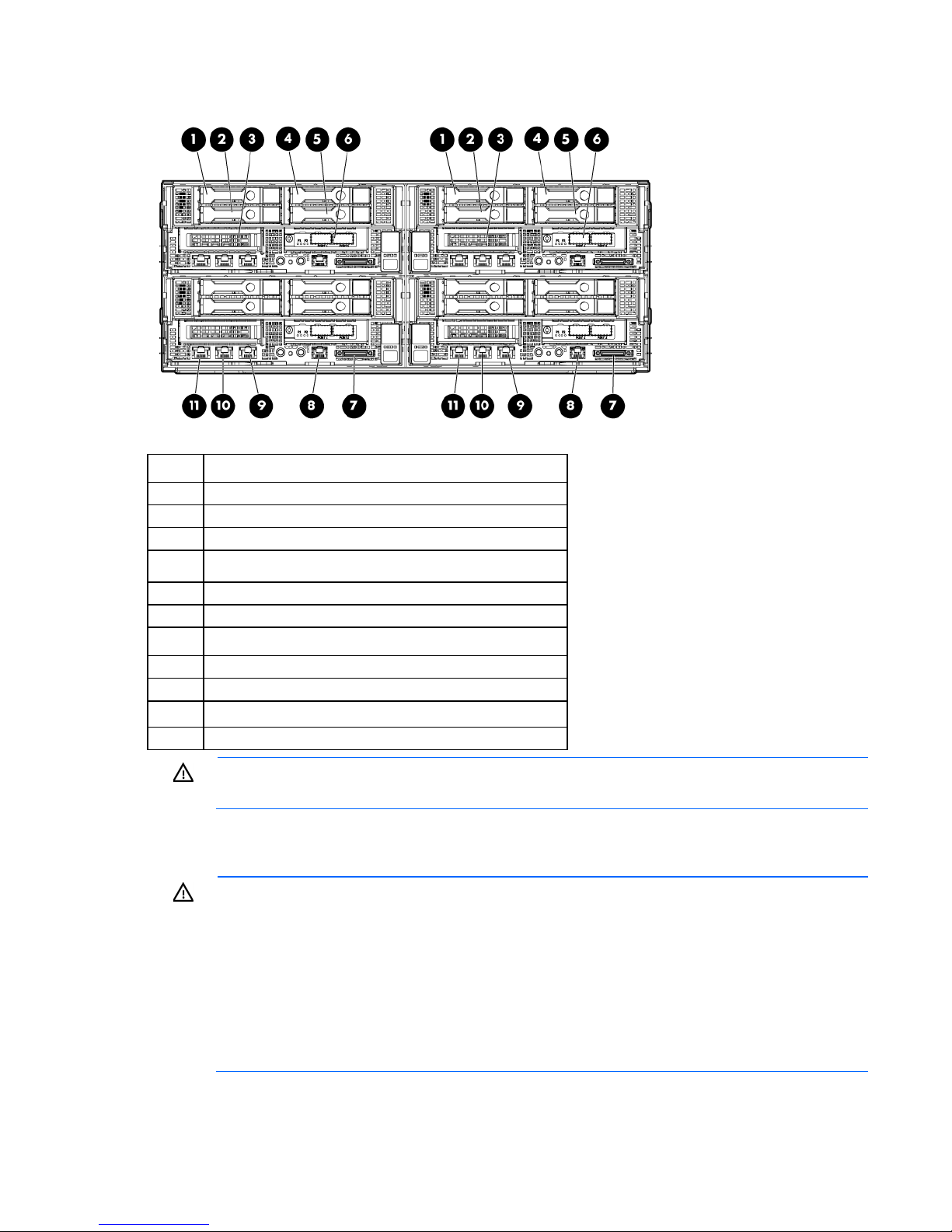
Front panel components
Item Description
1
2
3
4
5
6
7
8
9
10
11
Hot-plug hard drive, Bay 1 HDD 1
Hot-plug hard drive, Bay 1 HDD 2
Option bay 1, PCI riser board
Hot-plug hard drive, Bay 1 HDD 3
Hot-plug hard drive, Bay 1 HDD 4
Option bay 1, FlexibleLOM riser
SUV port
Serial port
NIC 1 network port
NIC 2 network port
iLO 4 network port
Component identification 6
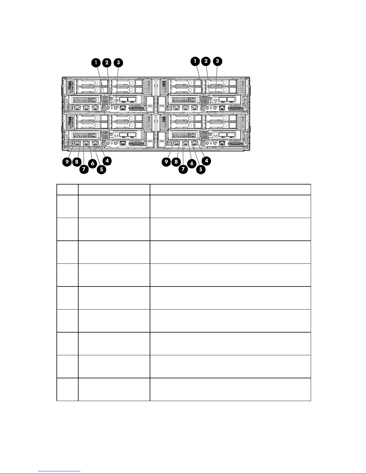
Front panel LEDs and buttons
Item Description Status
1
Power On/Standby button
and system power LED
2
3
4
5
6
7
8
9
Health LED Green—Normal
UID LED button Blue—Activated
NIC 1/iLO 4 speed LED Green—LAN connection using a GbE link
NIC 1/iLO 4 activity LED Flashing green—Network data activity exists.
NIC 2 speed LED Green—LAN connection using a GbE link
NIC 2 activity LED Flashing green—Network data activity exists.
iLO 4 network activity LED Flashing green—Network data activity exists.
iLO 4 network speed LED Green—LAN connection using a GbE link
Green—System on
Amber—System shut down, but power still applied.
Off—Power cord is not attached, or power supply has failed.
Flashing amber—System degraded
Flashing red—System critical
Flashing blue—System is being remotely managed.
Off—Deactivated
Amber—LAN connection using a 10 Mbps/100 Mbps link
Off—No LAN connection exists.
Off—No network data activity exists, or no network connection
exists.
Amber—LAN connection using a 10 Mbps/100 Mbps link
Off—No LAN connection exists.
Off—No network data activity exists, or no network connection
exists.
Off—No network data activity exists, or no network connection
exists.
Amber—LAN connection using a 10 Mbps/100 Mbps link
Off—No LAN connection exists.
Component identification 7
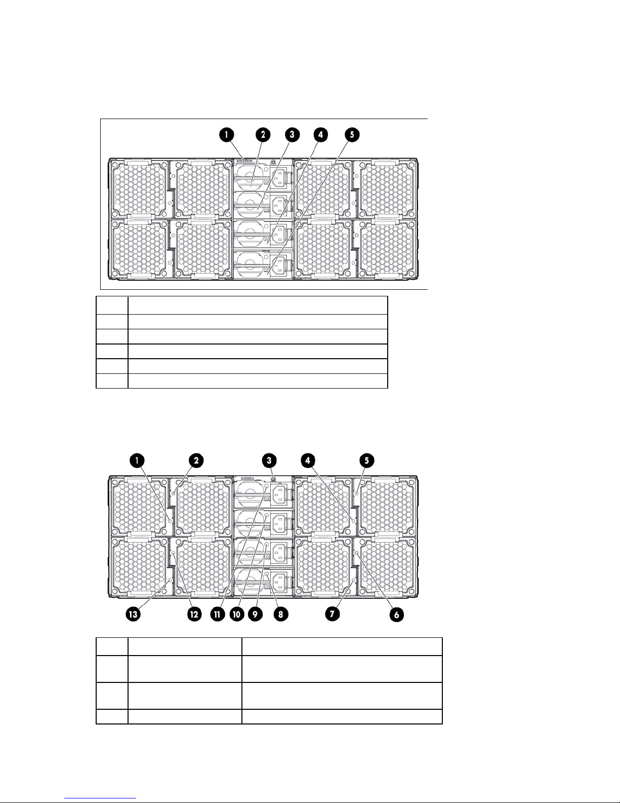
Rear panel components
Power supply 1
The server has four power supplies, eight fans, and a single SLAPM interface located on the rear panel of the
chassis.
Item Description
1
2
3
4
5
SLAPM interface
Power supply 4
Power supply 3
Power supply 2
Rear panel LEDs and buttons
Item Description Status
1
2
3
Fan 8/16 power LED Off—Normal
Fan 7/15 power LED Off—Normal
UID LED button Blue—Activated
Amber—Fan has failed.
Amber—Fan has failed.
Component identification 8

Fan 1/9 power LED
Off—Normal
Fan 6/14 power LED
Off—Normal
SATA hard drive connector 1
Item Description Status
Flashing blue—System is being remotely
managed.
Off—Deactivated
4
5
6
7
8
9
10
11
12
13
Fan 4/12 power LED Off—Normal
Amber—Fan has failed.
Fan 3/11 power LED Off—Normal
Amber—Fan has failed.
Amber—Fan has failed.
Fan 2/10 power LED Off—Normal
Amber—Fan has failed.
Power supply 1 power LED Green—Normal
Off—No AC power
Power supply 2 power LED Green—Normal
Off—No AC power
Power supply 3 power LED Green—Normal
Off—No AC power
Power supply 4 power LED Green—Normal
Off—No AC power
Fan 5/13 power LED Off—Normal
Amber—Fan has failed.
Amber—Fan has failed.
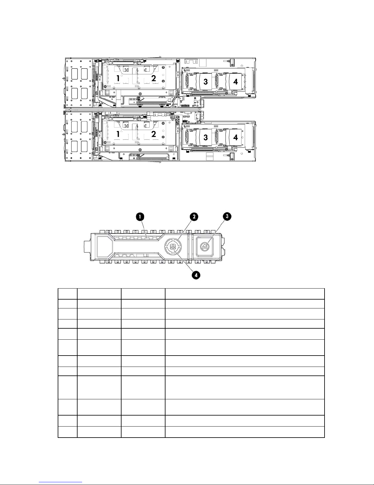
System board components
Item Description
1
2
3
Cache module connector
x24 riser connector
Component identification 9

Item Description
This server supports PCIe Gen3 only in the FlexibleLOM slot. PCIe Gen2 is supported in
4
5
6
7
SATA hard drive connector 2
System battery
Processor socket 2
Processor 2 DIMM slots
8
9
10
11
12
13
14
15
16
17
18
19
20
21
Power connector
RPS connector
x32 riser connector
Processor 1 DIMM slots
Processor socket 1 (populated)
Mini-SAS hard drive connector port 2i
Mini-SAS hard drive connector port 1i
Internal USB connector
uSD card slot
Data LED connector
x16 FlexibleLOM slot
System maintenance switch
Trusted Platform Module
NMI header
NOTE:
all other slots.
DIMM slot locations
DIMM slots are numbered sequentially (1 through 8) for each processor. The supported AMP modes use the
alpha assignments for population order, and the slot numbers designate the DIMM slot ID for spare
replacement.
Component identification 10
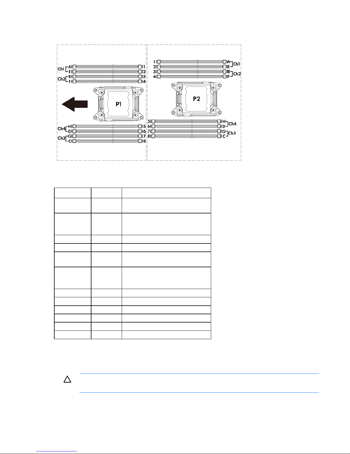
The arrow points to the front of the node.
Off
Off = iLO 4 security is enabled.
System maintenance switch
Position Default Function
S1
S2
S3
S4
S5
S6
S7
S8
S9
S10
S11
S12
Off Off = System configuration can be
Off Reserved
Off Reserved
Off Off = Power-on password is enabled.
Off Off = No function
— Reserved
— Reserved
— Reserved
— Reserved
— Reserved
— Reserved
On = iLO 4 security is disabled.
changed.
On = System configuration is locked.
On = Power-on password is disabled.
On = ROM reads system configuration
as invalid.
To access redundant ROM, set S1, S5, and S6 to on.
When the system maintenance switch position 6 is set to the On position, the system is prepared to erase all
system configuration settings from both CMOS and NVRAM.
CAUTION: Clearing CMOS and/or NVRAM deletes configuration information. Be sure to
properly configure the server or data loss could occur.
Component identification 11
NMI header
The NMI header enables administrators to perform a memory dump before performing a hard reset. Crash
dump analysis is an essential part of eliminating reliability issues, such as hangs or crashes in operating
systems, device drivers, and applications. Many crashes can freeze a system, requiring you to perform a
hard reset. Resetting the system erases any information that supports root cause analysis.
When a Windows® operating system crashes, a blue-screen trap appears. When this trap appears,
Microsoft® recommends that system administrators perform an NMI event by temporarily shorting the NMI
header with a jumper. The NMI event enables a hung system to become responsive again.
For additional information, see the HP website
(http://h20000.www2.hp.com/bc/docs/support/SupportManual/c00797875/c00797875.pdf).
Device numbers
• Front hot-plug hard drive bay numbers (box 1)
Component identification 12
• Rear SFF hard drive bay numbers (box 0)
Flashing blue
The drive carrier firmware is being updated or requires an update.
Drive LED definitions
Item LED Status Definition
1
2
3
4
Locate Solid blue The drive is being identified by a host application.
Activity ring Rotating green Drive activity
Off No drive activity
Do not remove Solid white Do not remove the drive. Removing the drive causes one or more of
Off Removing the drive does not cause a logical drive to fail.
Drive status Solid green The drive is a member of one or more logical drives.
Flashing green The drive is rebuilding or performing a RAID migration, stripe size
Flashing
amber/green
Flashing amber The drive is not configured and predicts the drive will fail.
Solid amber The drive has failed.
the logical drives to fail.
migration, capacity expansion, or logical drive extension, or is
erasing.
The drive is a member of one or more logical drives and predicts
the drive will fail.
Component identification 13

Item LED Status Definition
Off The drive is not configured by a RAID controller.
Component identification 14

Operations
Power up the server
To power up the server, press the Power On/Standby button.
Power down the node
Before powering down the node for any upgrade or maintenance procedures, perform a backup of critical
server data and programs.
IMPORTANT: When the node is in standby mode, auxiliary power is still being provided to the
To power down the node, use one of the following methods:
• Press and release the Power On/Standby button.
• Press and hold the Power On/Standby button for more than 4 seconds to force the node to enter
• Use a virtual power button selection through iLO 4.
system.
This method initiates a controlled shutdown of applications and the OS before the node enters standby
mode.
standby mode.
This method forces the node to enter standby mode without properly exiting applications and the OS.
If an application stops responding, you can use this method to force a shutdown.
This method initiates a controlled remote shutdown of applications and the OS before the node enters
standby mode.
Before proceeding, verify the node is in standby mode by observing that the system power LED is amber.
Remove the server from the chassis
1. Power down the server ("Power down the node" on page 15).
2. Disconnect all peripheral cables from the node.
Operations 15
3.
Remove the server from the chassis (on page 15).
4. Place the node on a flat, level work surface.
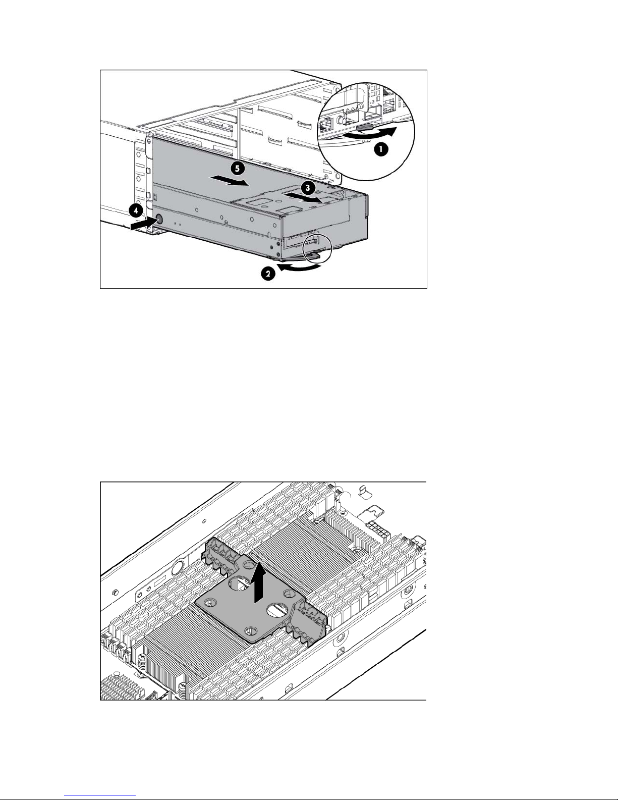
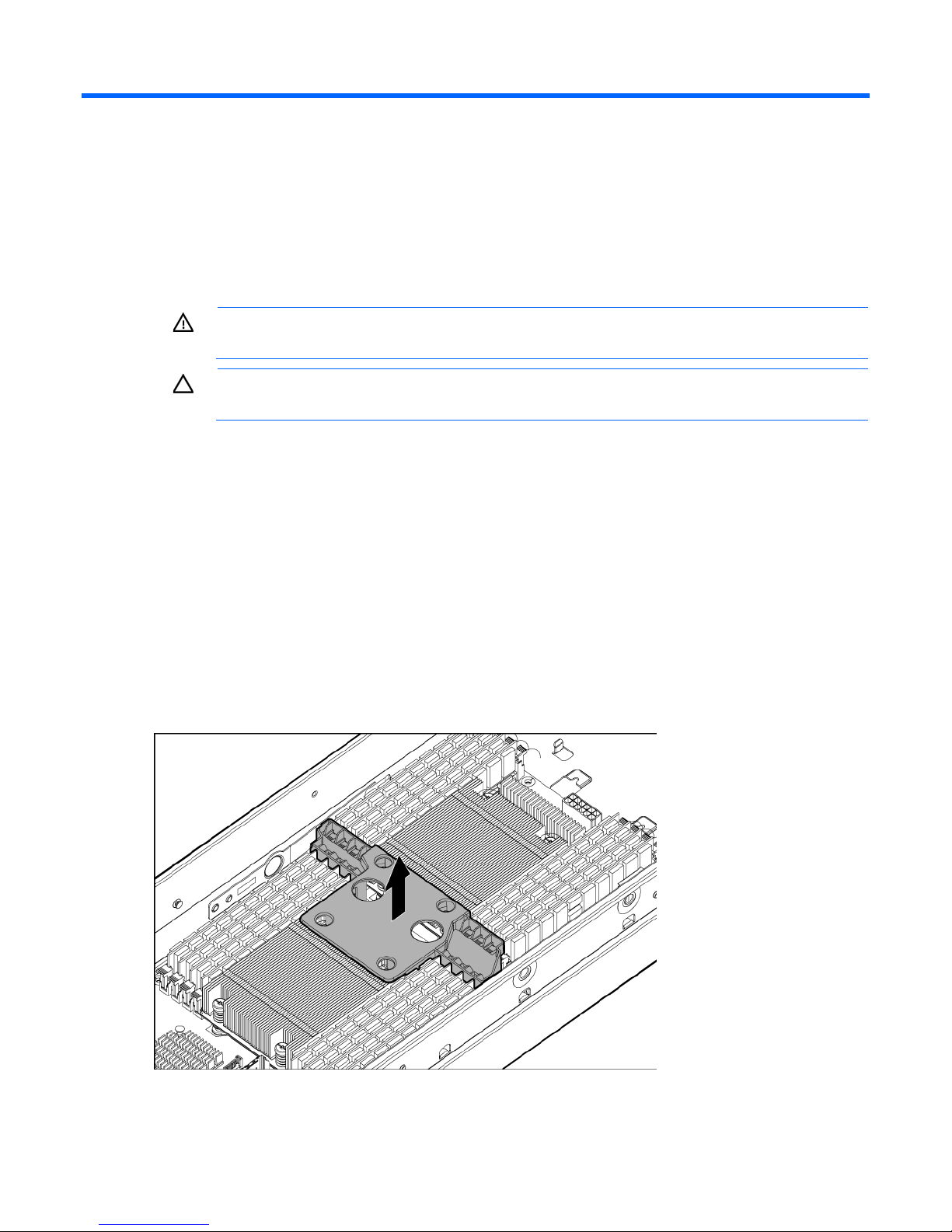
Remove the processor air baffle
To remove the component:
1. Power down the server ("Power down the node" on page 15).
2. Disconnect all peripheral cables from the node.
3. Remove the server from the chassis (on page 15).
4. Remove the front GPU module.
5. Remove the GPU bracket.
6. Remove the air baffle.
To replace the component, reverse the removal procedure.
Operations 16

Setup
Optional installation services
Delivered by experienced, certified engineers, HP Care Pack services help you keep your servers up and
running with support packages tailored specifically for HP ProLiant systems. HP Care Packs let you integrate
both hardware and software support into a single package. A number of service level options are available
to meet your needs.
HP Care Pack Services offer upgraded service levels to expand your standard product warranty with
easy-to-buy, easy-to-use support packages that help you make the most of your server investments. Some of
the Care Pack services are:
• Hardware support
o 6-Hour Call-to-Repair
o 4-Hour 24x7 Same Day
o 4-Hour Same Business Day
• Software support
o Microsoft®
o Linux
o HP ProLiant Essentials (HP SIM and RDP)
o VMWare
• Integrated hardware and software support
o Critical Service
o Proactive 24
o Support Plus
o Support Plus 24
• Startup and implementation services for both hardware and software
For more information on HP Care Pack Services, see the HP website
(http://www.hp.com/services/carepack).
Rack planning resources
The rack resource kit ships with all HP branded or Compaq branded 9000, 10000, and H9 series racks. For
more information on the content of each resource, see the rack resource kit documentation.
Optimum environment
When installing the server in a rack, select a location that meets the environmental standards described in
this section.
Setup 17

Space and airflow requirements
To allow for servicing and adequate airflow, observe the following space and airflow requirements when
deciding where to install a rack:
• Leave a minimum clearance of 63.5 cm (25 in) in front of the rack.
• Leave a minimum clearance of 76.2 cm (30 in) behind the rack.
• Leave a minimum clearance of 121.9 cm (48 in) from the back of the rack to the back of another rack
or row of racks.
HP nodes draw in cool air through the front door and expel warm air through the rear door. Therefore, the
front and rear rack doors must be adequately ventilated to allow ambient room air to enter the cabinet, and
the rear door must be adequately ventilated to allow the warm air to escape from the cabinet.
CAUTION: To prevent improper cooling and damage to the equipment, do not block the
When vertical space in the rack is not filled by a server or rack component, the gaps between the
components cause changes in airflow through the rack and across the servers. Cover all gaps with blanking
panels to maintain proper airflow.
The 9000 and 10000 Series Racks provide proper server cooling from flow-through perforations in the front
and rear doors that provide 64 percent open area for ventilation.
ventilation openings.
CAUTION: Always use blanking panels to fill empty vertical spaces in the rack. This arrangement
ensures proper airflow. Using a rack without blanking panels results in improper cooling that can
lead to thermal damage.
CAUTION: When using a Compaq branded 7000 series rack, install the high airflow rack door
insert (PN 327281-B21 for 42U rack, PN 157847-B21 for 22U rack) to provide proper
front-to-back airflow and cooling.
CAUTION: If a third-party rack is used, observe the following additional requirements to ensure
adequate airflow and to prevent damage to the equipment:
• Front and rear doors—If the 42U rack includes closing front and rear doors, you must allow
5,350 sq cm (830 sq in) of holes evenly distributed from top to bottom to permit adequate
airflow (equivalent to the required 64 percent open area for ventilation).
• Side—The clearance between the installed rack component and the side panels of the rack
must be a minimum of 7 cm (2.75 in).
Temperature requirements
To ensure continued safe and reliable equipment operation, install or position the system in a well-ventilated,
climate-controlled environment.
The maximum recommended ambient operating temperature (TMRA) for most server products is 35°C
(95°F). The temperature in the room where the rack is located must not exceed 35°C (95°F).
CAUTION: To reduce the risk of damage to the equipment when installing third-party options:
• Do not permit optional equipment to impede airflow around the server or to increase the
internal rack temperature beyond the maximum allowable limits.
• Do not exceed the manufacturer’s TMRA.
Setup 18

Power requirements
Installation of this equipment must comply with local and regional electrical regulations governing the
installation of information technology equipment by licensed electricians. This equipment is designed to
operate in installations covered by NFPA 70, 1999 Edition (National Electric Code) and NFPA-75, 1992
(code for Protection of Electronic Computer/Data Processing Equipment). For electrical power ratings on
options, refer to the product rating label or the user documentation supplied with that option.
WARNING: To reduce the risk of personal injury, fire, or damage to the equipment, do not
overload the AC supply branch circuit that provides power to the rack. Consult the electrical
When installing more than one server, you might need to use additional power distribution devices to safely
provide power to all devices. Observe the following guidelines:
• Balance the server power load between available AC supply branch circuits.
• Do not allow the overall system AC current load to exceed 80 percent of the branch circuit AC current
authority having jurisdiction over wiring and installation requirements of your facility.
CAUTION: Protect the server from power fluctuations and temporary interruptions with a
regulating uninterruptible power supply. This device protects the hardware from damage caused
by power surges and voltage spikes and keeps the system in operation during a power failure.
rating.
• Do not use common power outlet strips for this equipment.
• Provide a separate electrical circuit for the server.
For more information on the hot-plug power supply and calculators to determine server power consumption
in various system configurations, refer to the HP Enterprise Configurator website
(http://h30099.www3.hp.com/configurator/).
Electrical grounding requirements
The server must be grounded properly for proper operation and safety. In the United States, you must install
the equipment in accordance with NFPA 70, 1999 Edition (National Electric Code), Article 250, as well as
any local and regional building codes. In Canada, you must install the equipment in accordance with
Canadian Standards Association, CSA C22.1, Canadian Electrical Code. In all other countries, you must
install the equipment in accordance with any regional or national electrical wiring codes, such as the
International Electrotechnical Commission (IEC) Code 364, parts 1 through 7. Furthermore, you must be sure
that all power distribution devices used in the installation, such as branch wiring and receptacles, are listed
or certified grounding-type devices.
Because of the high ground-leakage currents associated with multiple servers connected to the same power
source, HP recommends the use of a PDU that is either permanently wired to the building’s branch circuit or
includes a nondetachable cord that is wired to an industrial-style plug. NEMA locking-style plugs or those
complying with IEC 60309 are considered suitable for this purpose. Using common power outlet strips for
the server is not recommended.
Rack warnings
Setup 19

WARNING: To reduce the risk of personal injury or damage to the equipment, be sure that:
• The leveling jacks are extended to the floor.
• The full weight of the rack rests on the leveling jacks.
• The stabilizing feet are attached to the rack if it is a single-rack installation.
• The racks are coupled together in multiple-rack installations.
• Only one component is extended at a time. A rack may become unstable if more than one
component is extended for any reason.
WARNING: To reduce the risk of personal injury or equipment damage when unloading a rack:
• At least two people are needed to safely unload the rack from the pallet. An empty 42U rack
can weigh as much as 115 kg (253 lb), can stand more than 2.1 m (7 ft) tall, and might
become unstable when being moved on its casters.
• Never stand in front of the rack when it is rolling down the ramp from the pallet. Always handle
the rack from both sides.
Contents of the server shipping carton
Unpack the server shipping carton and locate the materials and documentation necessary for installing the
server. All the rack mounting hardware necessary for installing the server into the rack is included with the
rack or the server.
The contents of the server shipping carton include:
• Server
• Power cord
• Printed setup documentation, Documentation CD, and software products
• Rack mounting hardware kit and documentation
In addition to these supplied items, you might need:
• T-10/T-15 Torx screwdriver
• Hardware options
• Operating system or application software
Installing the chassis
The chassis can be installed either in a rack or rack-free environment. For rack installations, install the rack
rails, and then install the chassis and other components.
For more information, see the HP ProLiant s6500 Chassis Setup and Installation Guide, Quick Deploy Rail
System Installation Instructions that ship with the rack hardware kit, and applicable installation instructions.
Installing options
Install any hardware options before initializing the node. For options installation information, see the
documentation that ships with the option. For node-specific information, see the node user guide on the HP
website (http://www.hp.com).
Setup 20
Installing components
WARNING: The node is very heavy. To reduce the risk of personal injury or damage to the
equipment:
• Reduce the weight of the node by removing the hard drives and power supplies before
installing the node into the rack.
• Get help to lift and stabilize the node during installation. When the node weighs more than
Before installing front or rear components into the chassis, review chassis bay numbering for each
component. For slot numbering information, see the quick setup instructions.
Based on the total number ordered and the planned configuration, install the following components:
• Nodes
• Power supplies
• System fans
For more information, see the appropriate chassis setup and installation guide and the node installation
instructions.
22.5 kg (50 lb), two people might be required to install the node into the rack.
CAUTION: Always plan the rack installation so that the heaviest item is on the bottom of the rack.
Install the heaviest item first, and continue to populate the rack from the bottom to the top.
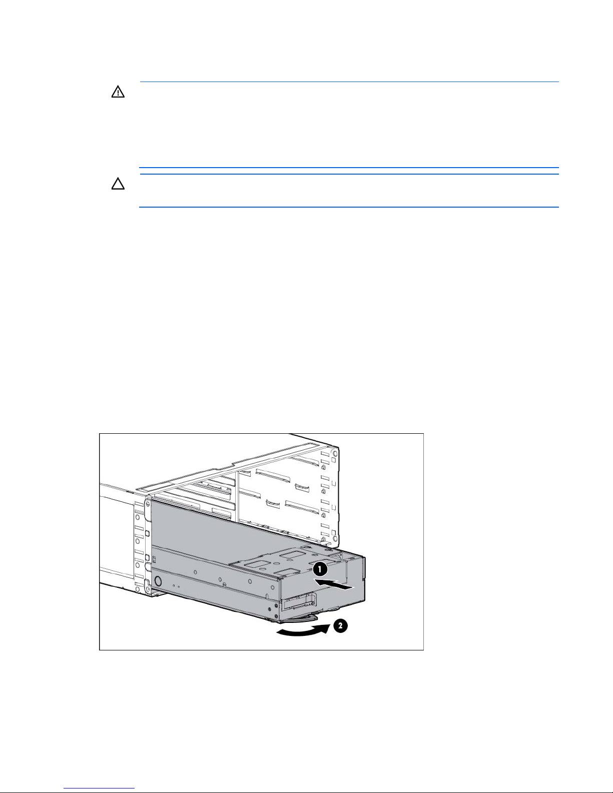
Installing the server into the chassis
1. Insert the system tray into the chassis.
2. Rotate the tray handle to lock.
Setup 21
3.
iLO 4 network port
Connect peripheral devices to the server.
Item Description
1
2
3
4
5
6
7
8
9
10
11
Hot-plug hard drive, Bay 1 HDD 1
Hot-plug hard drive, Bay 1 HDD 2
Option bay 1, PCI riser board
Hot-plug hard drive, Bay 1 HDD 3
Hot-plug hard drive, Bay 1 HDD 4
Option bay 1, FlexibleLOM riser
SUV port
Serial port
NIC 1 network port
NIC 2 network port
WARNING: To reduce the risk of electric shock, fire, or damage to the equipment, do not plug
telephone or telecommunications connectors into RJ-45 connectors.
4. Connect the power cords to the power supplies.
5. Connect the power cord to the AC power source.
WARNING: To reduce the risk of electric shock or damage to the equipment:
• Do not disable the power cord grounding plug. The grounding plug is an important safety
feature.
• Plug the power cord into a grounded (earthed) electrical outlet that is easily accessible at all
times.
• Unplug the power cord from the power supply to disconnect power to the equipment.
• Do not route the power cord where it can be walked on or pinched by items placed against it.
Pay particular attention to the plug, electrical outlet, and the point where the cord extends from
the server.
Setup 22

Powering up the chassis
Connect the AC or DC power cables, depending on the power configuration.
When the circuit breakers are powered, the chassis and HP ProLiant SL Advanced Power Manager have
power. By default, each installed component also powers up. Examine the HP ProLiant SL Advanced Power
Manager for any errors which may prevent installed components from powering up.
Configuring the chassis
For further information on setting up and configuring your system, see the HP ProLiant s6500 Chassis Quick
Setup Instructions and the HP ProLiant s6500 Chassis Setup and Installation Guide.
Powering on and selecting boot options
1. Connect the Ethernet cable and press the Power On/Standby button.
2. During the initial boot:
o To modify the server configuration ROM default settings, press F9 when prompted from the start up
sequence to enter the RBSU. By default, RBSU runs in the English language.
o If you do not need to modify the server configuration and are ready to install the system software,
press F10 to access Intelligent Provisioning.
NOTE: If an HP Smart Array controller has been added or is embedded in the system, the
controller defaults to a RAID configuration based on the size and number of hard drives installed.
For more information on modifying the controller default settings, see the documentation on the
Documentation CD.
For more information on automatic configuration, see the HP ROM-Based Setup Utility User Guide on the
Documentation CD or the iLO Management Engine Information Library
(http://www.hp.com/go/ilomgmtengine/docs).
Installing the system software
To access and configure Intelligent Provisioning on a single node:
1. Access Intelligent Provisioning by rebooting the server and pressing F10.
2. The first time you log into Intelligent Provisioning, follow the steps to set preferences and activate
Intelligent Provisioning.
3. From the Home screen, click Perform Maintenance, and then click Firmware Update.
4. Ensure the latest drivers are available for installation. Select Intelligent Provisioning Software from the
list of firmware and click Update. If the check box is not selected, the latest drivers are already installed.
5. From the Home screen, click Configure and Install.
6. Follow the on-screen prompts to finish the installation.
Registering the server
To register the server, refer to the HP Registration website (http://register.hp.com).
Setup 23
Hardware options installation
Introduction
If more than one option is being installed, read the installation instructions for all the hardware options and
identify similar steps to streamline the installation process.
WARNING: To reduce the risk of personal injury from hot surfaces, allow the drives and the
Processor option
internal system components to cool before touching them.
CAUTION: To prevent damage to electrical components, properly ground the server before
beginning any installation procedure. Improper grounding can cause electrostatic discharge.
1. Update the system ROM.
Locate and download the latest ROM version from the HP website (http://www.hp.com/support).
Follow the instructions on the website to update the system ROM.
2. Power down the server ("Power down the node" on page 15).
3. Remove the server from the chassis (on page 15).
4. Place the node on a flat, level work surface.
5. Remove any necessary components to obtain access to the system board. For procedures to remove
server components, see the maintenance and service guide.
6. Remove the air baffle.
Hardware options installation 24
WARNING: To reduce the risk of personal injury from hot surfaces, allow the drives and the
internal system components to cool before touching them.
CAUTION: To prevent possible node malfunction and damage to the equipment, multiprocessor
configurations must contain processors with the same part number.
CAUTION: The heatsink thermal interface media is not reusable and must be replaced if the
heatsink is removed from the processor after it has been installed.
CAUTION: To prevent possible node overheating, always populate processor socket 2 with a
processor and a heatsink or a processor socket cover and a heatsink blank.
IMPORTANT: Processor socket 1 must be populated at all times or the node does not function.
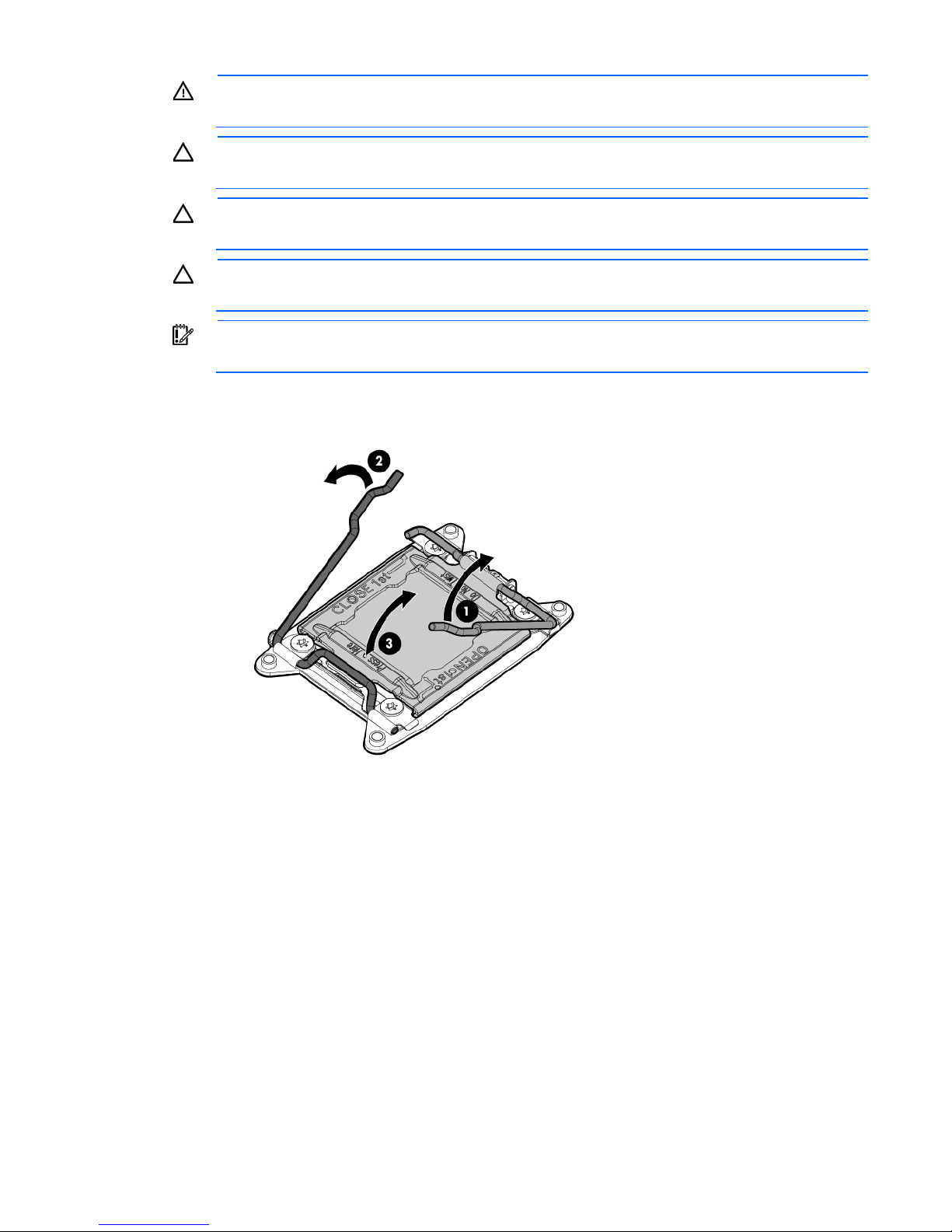
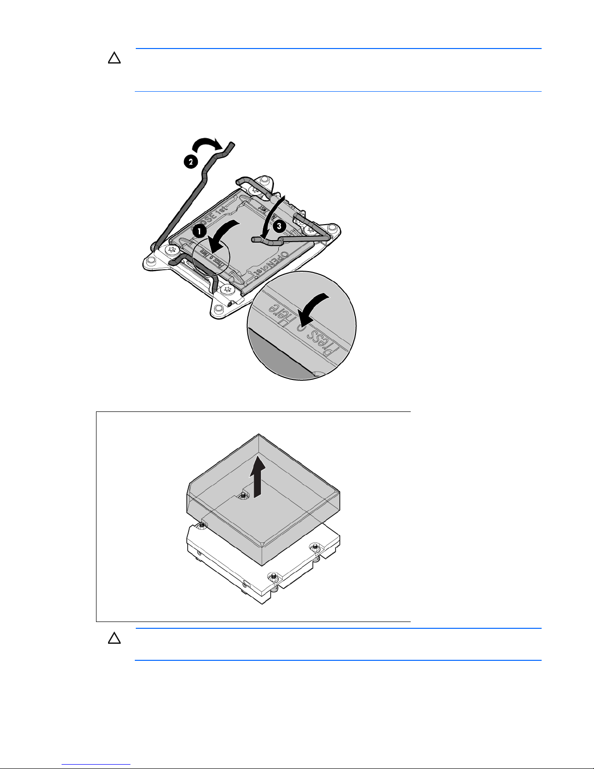
7. Open each of the processor locking levers in the order indicated, and then open the processor retaining
bracket.
Hardware options installation 25
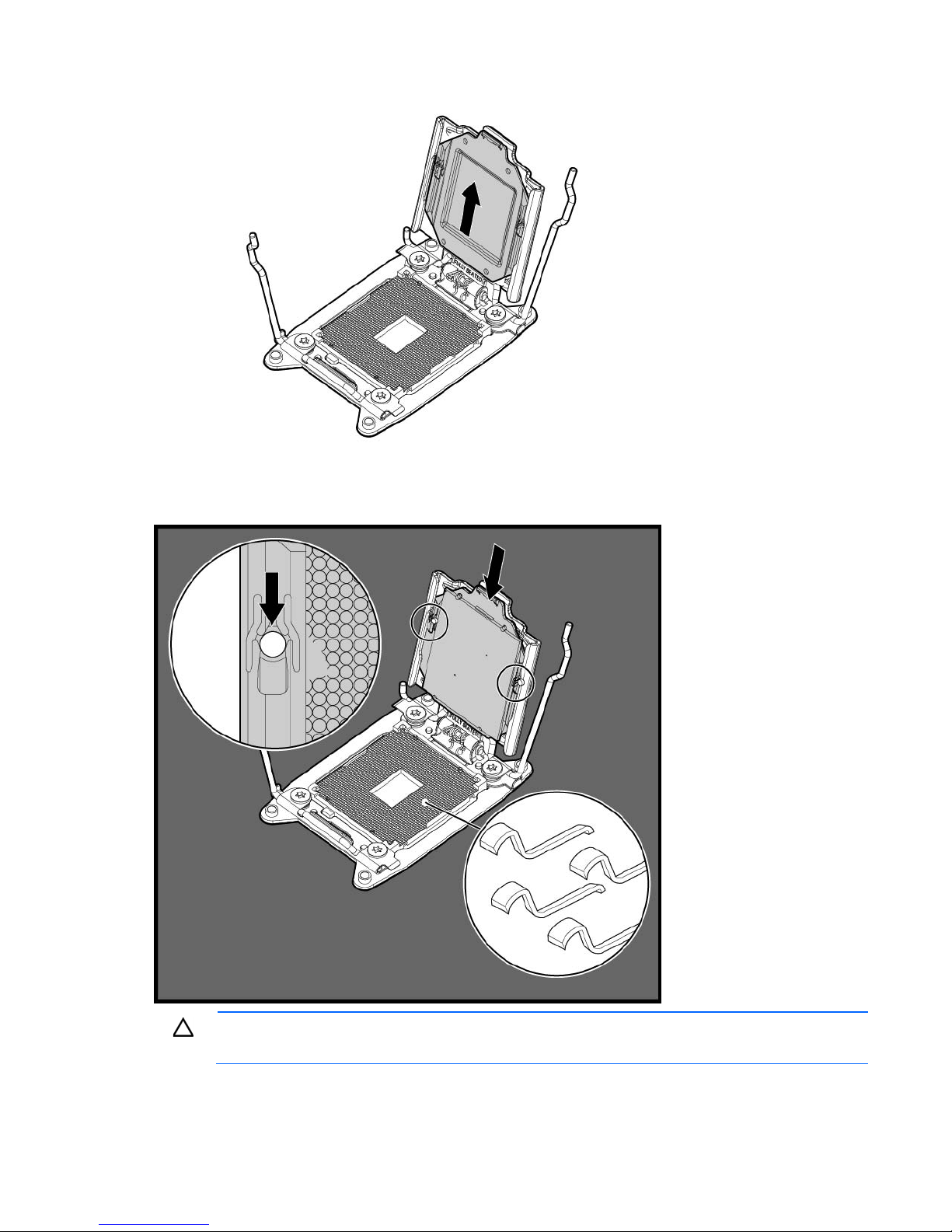
8.
Remove the clear processor socket cover. Retain the processor socket cover for future use.
9. Install the processor. Verify that the processor is fully seated in the processor retaining bracket by
visually inspecting the processor installation guides on either side of the processor. THE PINS ON THE
SYSTEM BOARD ARE VERY FRAGILE AND EASILY DAMAGED.
CAUTION: THE PINS ON THE SYSTEM BOARD ARE VERY FRAGILE AND EASILY DAMAGED. To
avoid damage to the system board, do not touch the processor or the processor socket contacts.
10. Close the processor retaining bracket. When the processor is installed properly inside the processor
retaining bracket, the processor retaining bracket clears the flange on the front of the socket.
Hardware options installation 26
CAUTION: Do not press down on the processor. Pressing down on the processor may cause
damage to the processor socket and the system board. Press only in the area indicated on the
11. Press and hold the processor retaining bracket in place, and then close each processor locking lever.
processor retaining bracket.
Press only in the area indicated on the processor retaining bracket.
12. Remove the thermal interface protective cover from the heatsink.
CAUTION: Heatsink retaining screws should be tightened in diagonally opposite pairs (in an "X"
pattern).
Hardware options installation 27

13.
Install the heatsink.
14. Install the air baffle.
15. Install the server into the chassis.
16. Power up the server.
Memory options
IMPORTANT: This node does not support mixing RDIMMs and UDIMMs. Attempting to mix any
The memory subsystem in this node can support RDIMMs or UDIMMs. Both types are referred to as DIMMs
when the information applies to all three types. When specified as RDIMM or UDIMM, the information
applies to that type only. All memory installed in the node must be the same type.
The node supports the following DIMM speeds:
• Single-rank and dual-rank PC3-12800 (DDR-1600) DIMMs operating at 1600, 1333, and 1066 MHz
• Single-rank and dual-rank PC3-10600 (DDR-1333) DIMMs operating at 1333 and 1066 MHz
Depending on the processor model, the number of DIMMs installed, and whether UDIMMs or RDIMMs are
installed, the memory clock speed might be reduced to 1333, 1066 or 800 MHz. For more information on
the effect of DIMM slot population, see "General DIMM slot population guidelines (on page 32)."
HP SmartMemory
HP SmartMemory, introduced for Gen8 servers, authenticates and unlocks certain features available only on
HP Qualified memory and verifies whether installed memory has passed HP qualification and test processes.
Qualified memory is performance-tuned for HP ProLiant and BladeSystem servers and provides future
enhanced support through HP Active Health and manageability software.
combination of these DIMMs can cause the server to halt during BIOS initialization.
Certain performance features are unique with HP SmartMemory. HP SmartMemory 1.35V DDR3-1333
Registered memory is engineered to achieve the same performance level as 1.5V memory. For example,
Hardware options installation 28

while the industry supports DDR3-1333 RDIMM at 1.5V, this Gen8 server supports DDR3-1333 RDIMM at
1.35V. This difference equates to up to 20% less power at the DIMM level with no performance penalty.
Memory subsystem architecture
The memory subsystem in this node is divided into channels. Each processor supports four channels, and
each channel supports two DIMM slots, as shown in the following table.
Channel Slot Slot number
1
2
3
4
For the location of the slot numbers, see "DIMM slot locations."
This multi-channel architecture provides enhanced performance in Advanced ECC mode. This architecture
also enables the Lockstep memory mode.
A
E
B
F
C
G
D
H
1
2
3
4
8
7
6
5
DIMM slots in this server are identified by number and by letter. Letters identify the population order. Slot
numbers indicate the DIMM slot ID for spare replacement.
Single-, dual-, and quad-rank DIMMs
To understand and configure memory protection modes properly, an understanding of single-, dual-, and
quad-rank DIMMs is helpful. Some DIMM configuration requirements are based on these classifications.
A single-rank DIMM has one set of memory chips that is accessed while writing to or reading from the
memory. A dual-rank DIMM is similar to having two single-rank DIMMs on the same module, with only one
rank accessible at a time. A quad-rank DIMM is, effectively, two dual-rank DIMMs on the same module. Only
one rank is accessible at a time. The node memory control subsystem selects the proper rank within the DIMM
when writing to or reading from the DIMM.
Dual- and quad-rank DIMMs provide the greatest capacity with the existing memory technology. For
example, if current DRAM technology supports 2-GB single-rank DIMMs, a dual-rank DIMM would be 4-GB,
and a quad-rank DIMM would be 8-GB.
Hardware options installation 29
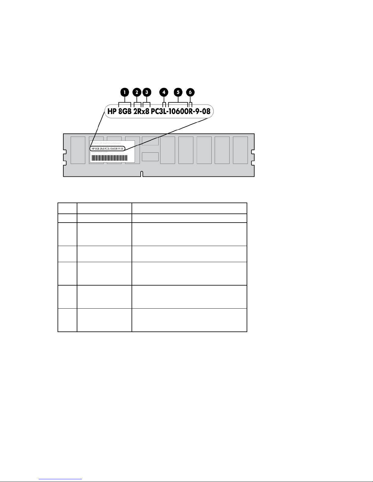
DIMM identification
To determine DIMM characteristics, use the label attached to the DIMM and the following illustration and
table.
Item Description Definition
1
2
3
4
5
6
Size —
Rank 1R = Single-rank
2R = Dual-rank
4R = Quad-rank
Data width x4 = 4-bit
x8 = 8-bit
Voltage rating L = Low voltage (1.35v)
U = Ultra low voltage (1.25v)
Blank or omitted = Standard
Memory speed 12800 = 1600-MT/s
10600 = 1333-MT/s
8500 = 1066-MT/s
DIMM type R = RDIMM (registered)
E = UDIMM (unbuffered with ECC)
L = LRDIMM (load reduced)
For the latest supported memory information, see the QuickSpecs on the HP website
(http://h18000.www1.hp.com/products/quickspecs/ProductBulletin.html). At the website, choose the
geographic region, and then locate the product by name or product category.
Memory configurations
To optimize node availability, the node supports the following AMP modes:
• Advanced ECC—Provides up to 4-bit error correction and enhanced performance over Lockstep mode.
This mode is the default option for this node.
• Online spare memory—Provides protection against failing or degraded DIMMs. Certain memory is
reserved as spare, and automatic failover to spare memory occurs when the system detects a DIMM that
Hardware options installation 30
 Loading...