

HP ProLiant SL250s G8, ProLiant SL230s G8 User Manual

HP ProLiant SL250s Gen8 Server
Part Number: 666298-003
User Guide
Abstract
This document provides detailed instructions to configure and use the HP ProLiant SL250s Gen8 Server.
September 2013
Edition: 3

© Copyright 2012, 2013 Hewlett-Packard Development Company, L.P.
The information contained herein is subject to change without notice. The only warranties for HP products and services are set forth in the express
warranty statements accompanying such products and services. Nothing herein should be construed as constituting an additional warranty. HP shall
not be liable for technical or editorial errors or omissions contained herein.
Confidential computer software. Valid license from HP required for possession, use or copying. Consistent with FAR 12.211 and 12.212,
Commercial Computer Software, Computer Software Documentation, and Technical Data for Commercial Items are licensed to the U.S. Government
under vendor’s standard commercial license.
Microsoft® and Windows® are U.S. registered trademarks of Microsoft Corporation.

Contents
Component identification ............................................................................................................... 6
Front panel components ............................................................................................................................. 6
Front panel LEDs and buttons ...................................................................................................................... 7
Rear panel components .............................................................................................................................. 8
Rear panel LEDs and buttons ....................................................................................................................... 9
System board components .......................................................................................................................... 9
DIMM slot locations ....................................................................................................................... 10
System maintenance switch ............................................................................................................. 11
NMI functionality ........................................................................................................................... 12
Drive numbering ..................................................................................................................................... 12
Hot-plug drive LED definitions .................................................................................................................... 13
Operations ................................................................................................................................. 15
Power up the server ................................................................................................................................. 15
Power down the server ............................................................................................................................. 15
Remove the server from the chassis ............................................................................................................ 15
Remove the front GPU cage ...................................................................................................................... 16
Install the front GPU cage ......................................................................................................................... 17
Remove the interposer board .................................................................................................................... 18
Install the interposer board ....................................................................................................................... 19
Remove the front GPU bracket .................................................................................................................. 19
Install the front GPU bracket...................................................................................................................... 20
Remove the processor air baffle ................................................................................................................ 21
Install the processor air baffle ................................................................................................................... 21
Removing the SFF hot-plug drive cage ........................................................................................................ 22
Installing the SFF hot-plug drive cage ......................................................................................................... 23
Remove the PCI riser cage ........................................................................................................................ 23
Install the PCI riser cage ........................................................................................................................... 24
Remove the FlexibleLOM riser cage ........................................................................................................... 25
Install the FlexibleLOM riser cage .............................................................................................................. 25
Setup ......................................................................................................................................... 27
Optional installation services .................................................................................................................... 27
Optimum environment .............................................................................................................................. 27
Space and airflow requirements ...................................................................................................... 27
Temperature requirements ............................................................................................................... 28
Power requirements ....................................................................................................................... 29
Electrical grounding requirements .................................................................................................... 29
Rack warnings ........................................................................................................................................ 29
Contents of the server shipping carton ........................................................................................................ 30
Installing the chassis ................................................................................................................................ 30
Installing options ..................................................................................................................................... 30
Installing the components ......................................................................................................................... 31
Installing the server into the chassis ............................................................................................................ 31
Powering up the chassis ........................................................................................................................... 32
Configuring the chassis ............................................................................................................................ 32
Powering on and selecting boot options ..................................................................................................... 32
Contents 3

Installing the system software .................................................................................................................... 32
Registering the server ............................................................................................................................... 33
Hardware options installation ....................................................................................................... 34
Introduction ............................................................................................................................................ 34
Processor option ...................................................................................................................................... 34
Memory options ...................................................................................................................................... 38
HP SmartMemory .......................................................................................................................... 39
Memory subsystem architecture ....................................................................................................... 39
Single-, dual-, and quad-rank DIMMs ............................................................................................... 39
DIMM identification ....................................................................................................................... 40
Memory protection modes .............................................................................................................. 40
General DIMM slot population guidelines ......................................................................................... 42
Installing a DIMM .......................................................................................................................... 43
Drive guidelines ...................................................................................................................................... 44
Installing a hot-plug drive ................................................................................................................ 45
Installing SFF quick-release drive cages ............................................................................................ 45
Installing a quick-release drive ......................................................................................................... 50
Controller options .................................................................................................................................... 51
Installing the FBWC module and capacitor pack ............................................................................... 52
Smart Array enablement Mini-SAS cable option ................................................................................ 55
Expansion board options .......................................................................................................................... 57
Installing an expansion board ......................................................................................................... 57
GPU installation ...................................................................................................................................... 59
Large BAR setting for GPU installation .............................................................................................. 59
GPU population rules ..................................................................................................................... 60
Installing GPU brackets .................................................................................................................. 60
Connecting the SUV cable ........................................................................................................................ 67
Redundant hot-plug power supply option .................................................................................................... 68
HP Trusted Platform Module option ............................................................................................................ 70
Installing the Trusted Platform Module board ..................................................................................... 71
Retaining the recovery key/password .............................................................................................. 72
Enabling the Trusted Platform Module ............................................................................................... 73
Cabling ..................................................................................................................................... 74
Cabling overview .................................................................................................................................... 74
Power cabling......................................................................................................................................... 74
System board power cabling .......................................................................................................... 74
SFF hot-plug drive cage .................................................................................................................. 75
Front quick-release cage ................................................................................................................. 75
Rear quick-release drive cage ......................................................................................................... 76
Front GPU .................................................................................................................................... 77
Rear GPU ..................................................................................................................................... 78
Mini-SAS cabling .................................................................................................................................... 79
SFF hot-plug drive cage .................................................................................................................. 79
Front quick-release drive cage ......................................................................................................... 79
Rear quick-release drive cage ......................................................................................................... 80
FBWC capacitor pack cabling .................................................................................................................. 81
Software and configuration utilities ............................................................................................... 83
Server mode ........................................................................................................................................... 83
HP product QuickSpecs ............................................................................................................................ 83
HP iLO Management Engine ..................................................................................................................... 83
HP iLO ......................................................................................................................................... 83
Contents 4

Intelligent Provisioning .................................................................................................................... 85
Scripting Toolkit ............................................................................................................................ 86
HP Service Pack for ProLiant ..................................................................................................................... 86
HP Smart Update Manager ............................................................................................................. 87
HP ROM-Based Setup Utility ..................................................................................................................... 87
Using RBSU .................................................................................................................................. 88
Auto-configuration process .............................................................................................................. 88
Boot options ................................................................................................................................. 89
Configuring AMP modes ................................................................................................................ 89
Re-entering the server serial number and product ID ........................................................................... 89
Utilities and features ................................................................................................................................ 90
Array Configuration Utility .............................................................................................................. 90
Option ROM Configuration for Arrays ............................................................................................. 91
ROMPaq utility .............................................................................................................................. 91
Automatic Server Recovery ............................................................................................................. 91
USB support .................................................................................................................................. 91
Redundant ROM support ................................................................................................................ 92
Keeping the system current ....................................................................................................................... 92
Drivers ......................................................................................................................................... 92
Software and firmware ................................................................................................................... 93
Version control .............................................................................................................................. 93
HP operating systems and virtualization software support for ProLiant servers ........................................ 93
HP Technology Service Portfolio ...................................................................................................... 93
Change control and proactive notification ........................................................................................ 94
Troubleshooting .......................................................................................................................... 95
Troubleshooting resources ........................................................................................................................ 95
System battery ........................................................................................................................................ 95
Regulatory information ................................................................................................................ 97
Safety and regulatory compliance ............................................................................................................. 97
Belarus Kazakhstan Russia marking ........................................................................................................... 97
Turkey RoHS material content declaration ................................................................................................... 97
Ukraine RoHS material content declaration ................................................................................................. 97
Warranty information .............................................................................................................................. 97
Electrostatic discharge ................................................................................................................. 98
Preventing electrostatic discharge .............................................................................................................. 98
Grounding methods to prevent electrostatic discharge .................................................................................. 98
Specifications ............................................................................................................................. 99
Environmental specifications ..................................................................................................................... 99
Server specifications ................................................................................................................................ 99
Hot-plug power supply calculations ............................................................................................................ 99
Support and other resources ...................................................................................................... 100
Before you contact HP ............................................................................................................................ 100
HP contact information ........................................................................................................................... 100
Customer Self Repair ............................................................................................................................. 100
Acronyms and abbreviations ...................................................................................................... 108
Documentation feedback ........................................................................................................... 112
Index ....................................................................................................................................... 113
Contents 5
Component identification
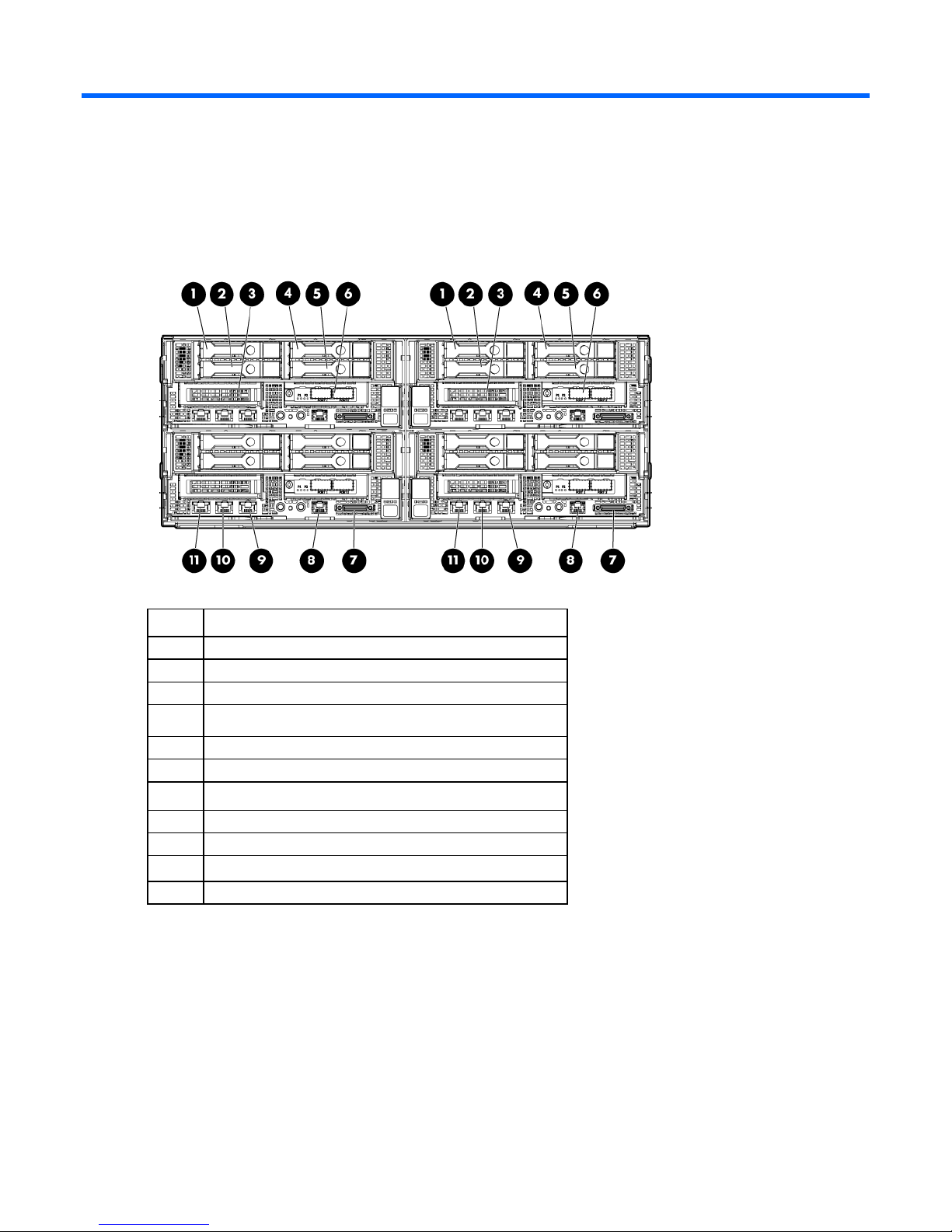
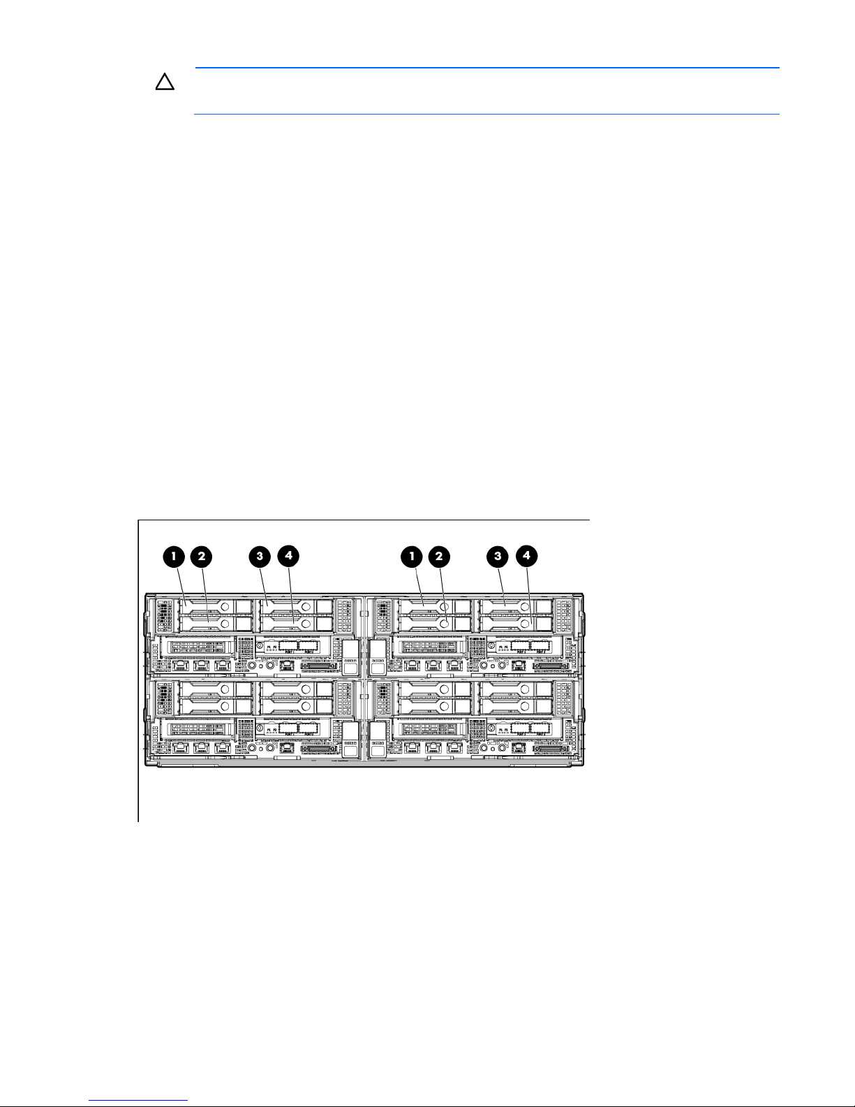
Front panel components
Item Description
1
2
3
4
5
6
7
8
9
10
11
Hot-plug drive, Box 1 drive 1
Hot-plug drive, Box 1 drive 2
Option bay 1, PCI riser
Hot-plug drive, Box 1 drive 3
Hot-plug drive, Box 1 drive 4
Option bay 1, FlexibleLOM riser
SUV port
Serial port
NIC 1 network port
NIC 2 network port
iLO 4 network port
Component identification 6
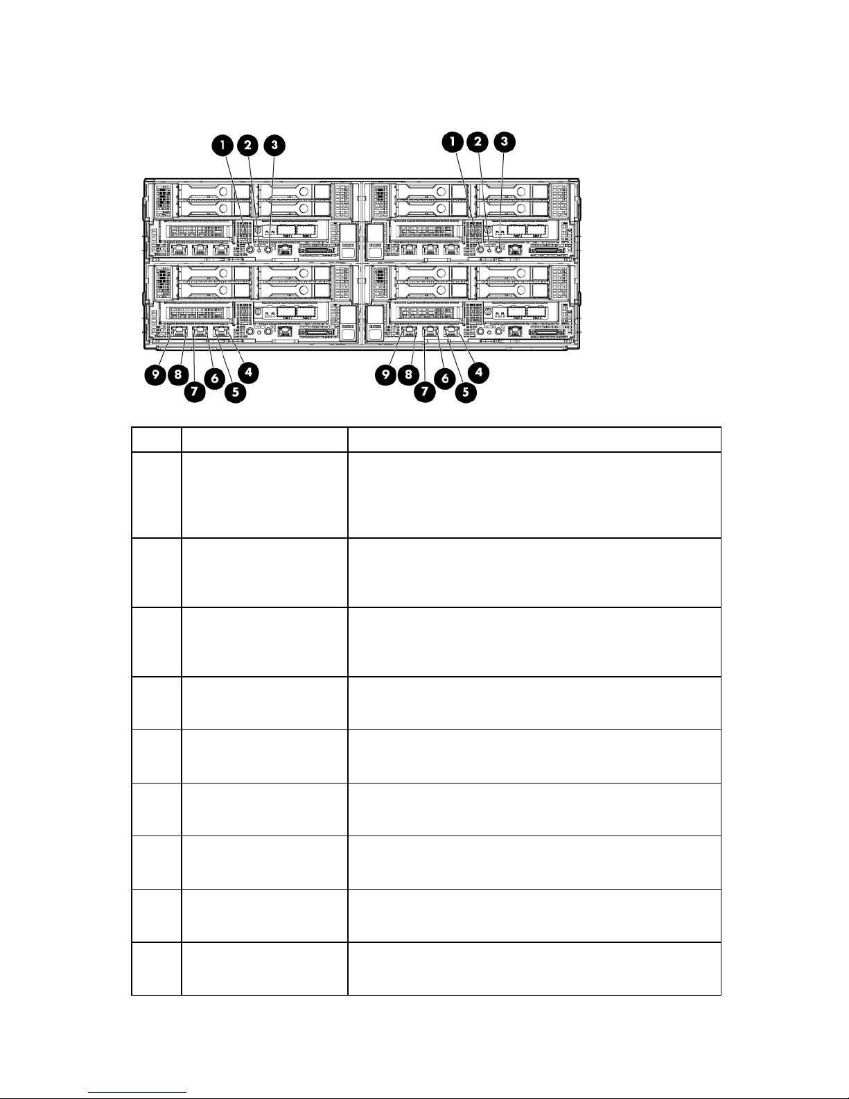
Front panel LEDs and buttons
NIC 2 speed LED
Green = LAN connection using a GbE link
Item Description Status
1
2
3
4
5
6
7
8
9
Power On/Standby button
and system power LED
Health LED Solid green = Normal
UID button/LED Solid blue = Activated
NIC 1/iLO 4 speed LED Green = LAN connection using a GbE link
NIC 1/iLO 4 status LED Solid green = Link to network
NIC 2 status LED Solid green = Link to network
iLO 4 status LED Solid green = Link to network
iLO 4 speed LED Green = LAN connection using a GbE link
Solid green = System on
Flashing green (1 Hz/cycle per sec) = Performing power on
sequence
Solid amber = System in standby
Off = No power present*
Flashing amber = System degraded
Flashing red (1 Hz/cycle per sec) = System critical
Fast-flashing red (4 Hz/cycles per sec) = Power fault**
Flashing blue (1 Hz/cycle per sec) = Remote management or
firmware upgrade in progress
Off = Deactivated
Amber = LAN connection using a 10 Mbps/100 Mbps link
Off = No link exists
Flashing green (1 Hz/cycle per sec) = Network active
Off = No network activity
Amber = LAN connection using a 10 Mbps/100 Mbps link
Off = No link exists
Flashing green (1 Hz/cycle per sec) = Network active
Off = No network activity
Flashing green (1 Hz/cycle per sec) = Network active
Off = No network activity
Amber = LAN connection using a 10 Mbps/100 Mbps link
Off = No link exists
Component identification 7
Fan 4
* Facility power is not present, power cord is not attached, no power supplies are installed, power supply failure has
occurred, or the power button cable is disconnected.
** To identify components in a degraded or critical state, see the iLO/BIOS logs and the server troubleshooting guide.
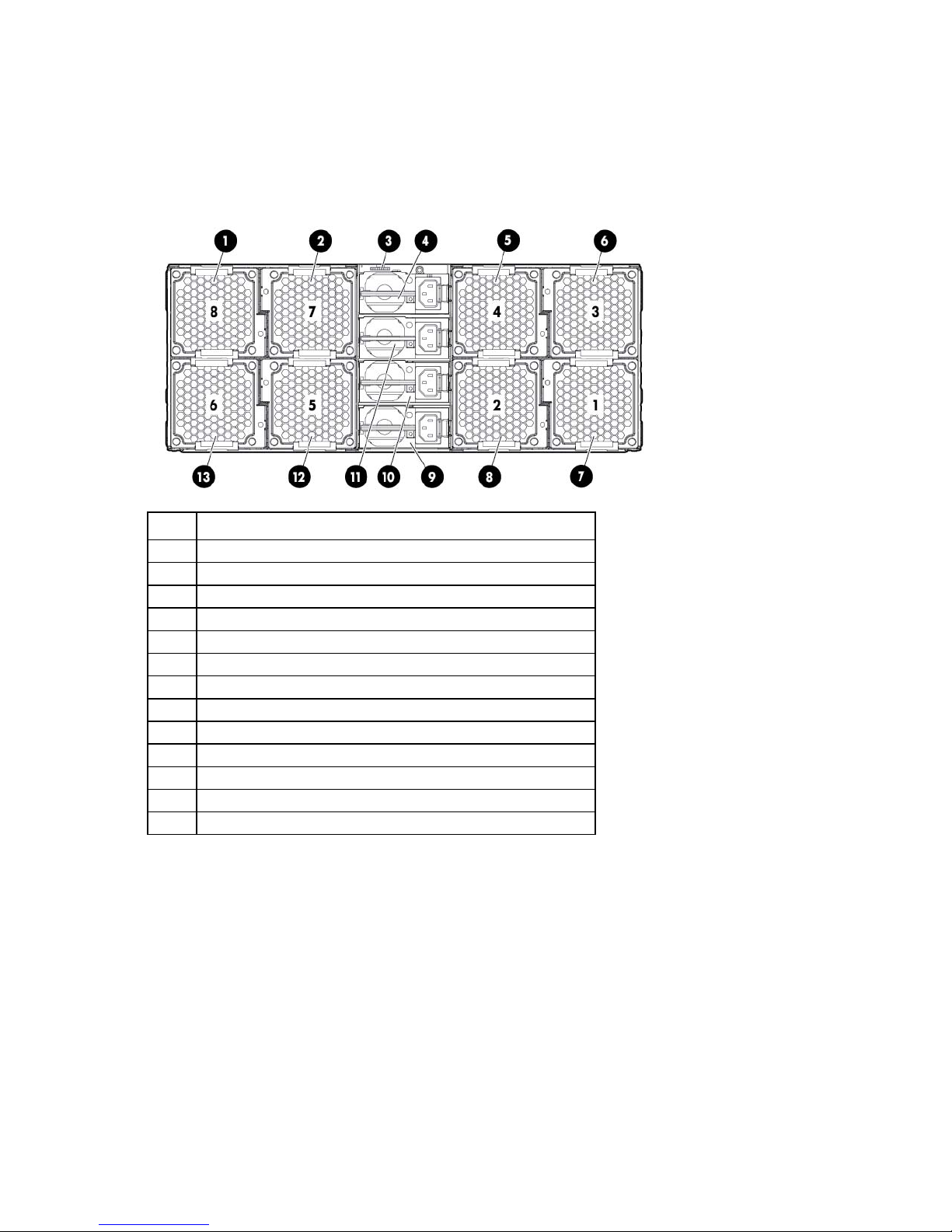
Rear panel components
Item Description
1
2
3
4
5
6
7
8
9
10
11
12
13
Fan 8
Fan 7
SLAPM interface
Power supply 4
Fan 3
Fan 1
Fan 2
Power supply 1
Power supply 2
Power supply 3
Fan 5
Fan 6
Component identification 8

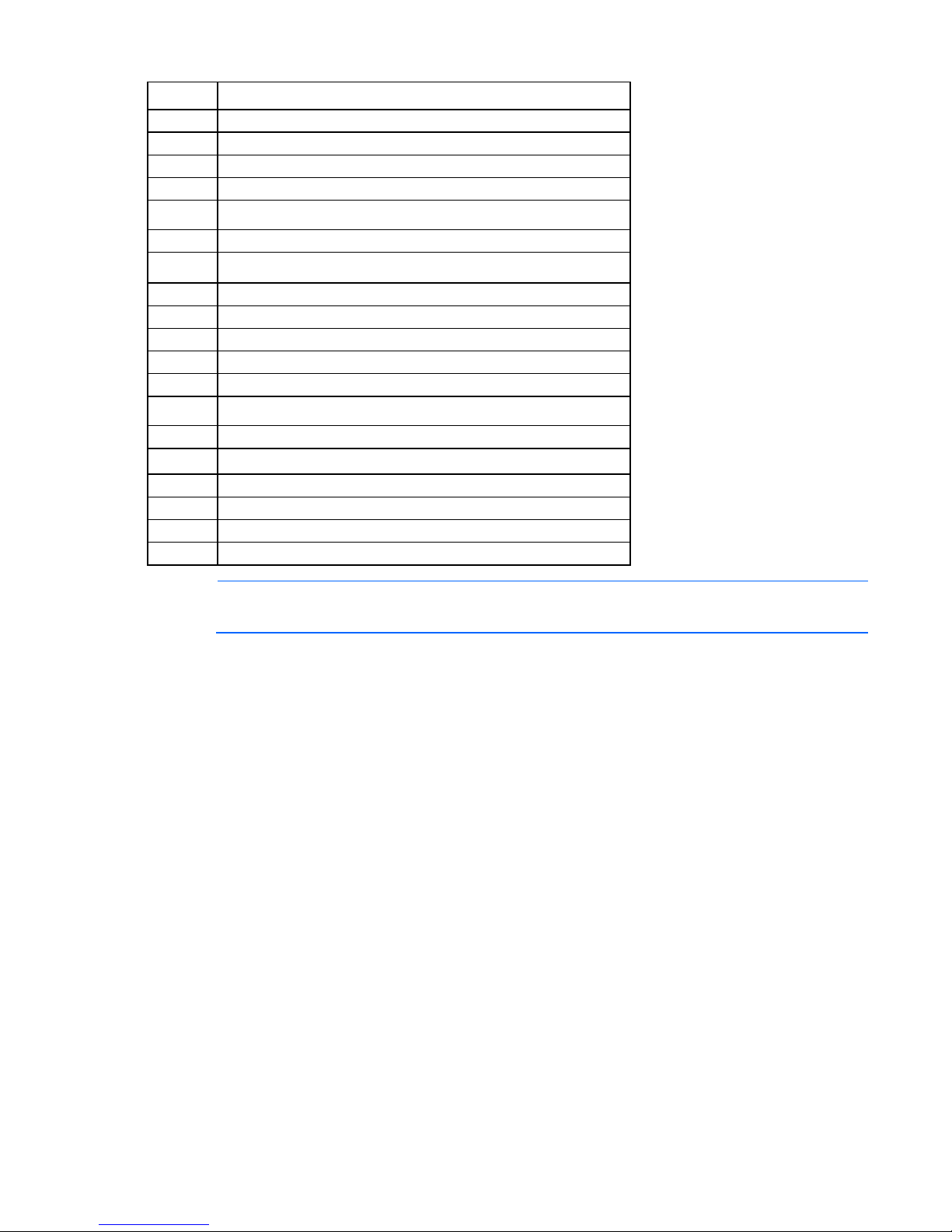
Rear panel LEDs and buttons
•
•
•
•
Item Description Status
1-2, 4-7,
12-13
3
8-11
System fan LEDs Off = Normal
Amber = Fan has failed
UID button/LED Solid blue = Activated
Flashing blue (1 Hz/cycle per sec) = Remote management or firmware
upgrade in progress
Off = Deactivated
Power supply LEDs Solid green = Normal
Off = One or more of the following conditions exists:
Power is unavailable
Power supply failed
Power supply is in standby mode
Power supply error
System board components
Component identification 9
System maintenance switch
Item Description
1
2
3
4
5
6
7
Cache module connector
PCIe x24 riser connector
SATA connector 2
SATA connector 1
System battery
Processor socket 2
Processor 2 DIMM slots
8
9
10
11
12
13
14
15
16
12-pin system board power connector
24-pin RPS connector
Processor 1 DIMM slots
Processor socket 1
Mini-SAS connector 2i
Mini-SAS connector 1i
microSD card slot
Hot-plug drive backplane sideband connector
FlexibleLOM x16 riser connector
17
18
19
TPM connector
NMI header
NOTE: This server supports PCIe Gen3 in the front LP PCIe slot and FlexibleLOM slot.
DIMM slot locations
DIMM slots are numbered sequentially (1 through 8) for each processor. The supported AMP modes use the
alpha assignments for population order, and the slot numbers designate the DIMM slot ID for spare
replacement.
Component identification 10
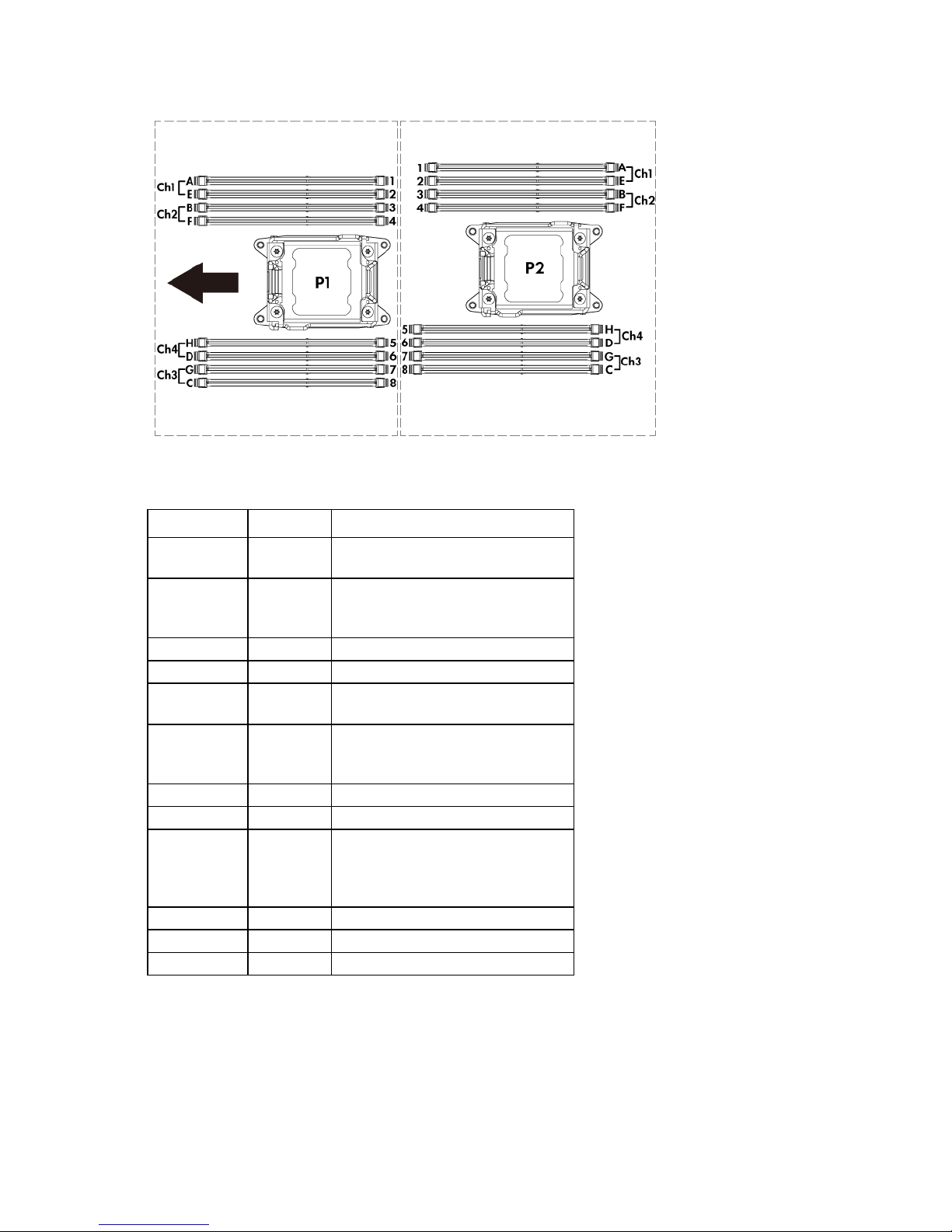
The arrow points to the front of the server.
Off
Off = iLO 4 security is enabled.
System maintenance switch
Position Default Function
S1
S2
S3
S4
S5
S6
S7
S8
S9
S10
S11
S12
Off Off = System configuration can be
Off Reserved
Off Reserved
Off Off = Power-on password is enabled.
Off Off = No function
— Reserved
— Reserved
— Off = PCIe 64-bit BAR function (large
— Reserved
— Reserved
— Reserved
On = iLO 4 security is disabled.
changed.
On = System configuration is locked.
On = Power-on password is disabled.
On = ROM reads system configuration
as invalid.
BAR) is disabled.
On = PCIe 64-bit BAR function (large
BAR) is enabled.
To access the redundant ROM, set S1, S5, and S6 to on.
When the system maintenance switch position 6 is set to the On position, the system is prepared to erase all
system configuration settings from both CMOS and NVRAM.
Component identification 11
CAUTION: Clearing CMOS and/or NVRAM deletes configuration information. Be sure to
properly configure the server or data loss could occur.
NMI functionality
An NMI crash dump creates a crash dump log before resetting a system which is not responding.
Crash dump log analysis is an essential part of diagnosing reliability problems, such as failures of operating
systems, device drivers, and applications. Many crashes freeze a system, and the only available action for
administrators is to restart the system. Resetting the system erases any information which could support
problem analysis, but the NMI feature preserves that information by performing a memory dump before a
system reset.
To force the system to invoke the NMI handler and generate a crash dump log, do one of the following:
• Use the iLO Virtual NMI feature.
• Short the NMI header ("System board components" on page 9).
For more information, see the HP website
(http://h20000.www2.hp.com/bc/docs/support/SupportManual/c00797875/c00797875.pdf).
Drive numbering
• Front hot-plug drive bay numbers (box 1)
Component identification 12
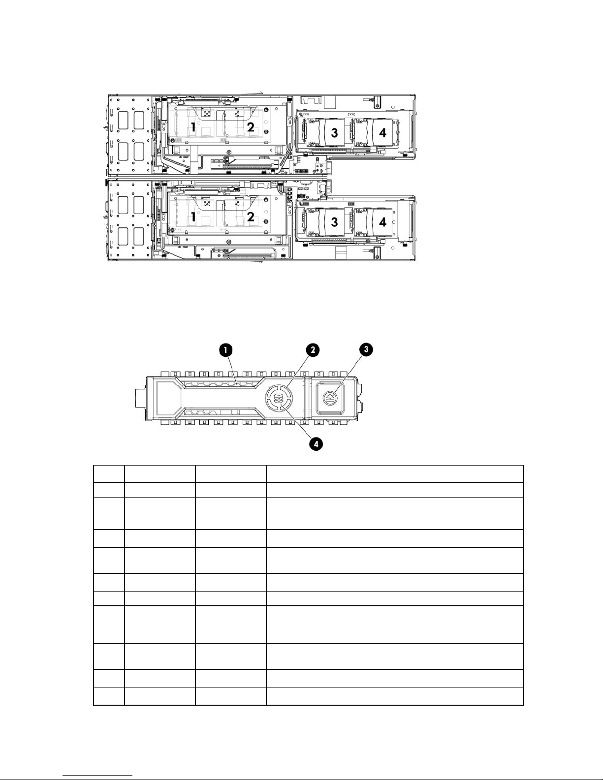
• Rear SFF drive bay numbers (box 0)
Hot-plug drive LED definitions
Item LED Status Definition
1
2
3
4
Locate Solid blue The drive is being identified by a host application.
Flashing blue The drive carrier firmware is being updated or requires an update.
Activity ring Rotating green Drive activity
Off No drive activity
Do not remove Solid white Do not remove the drive. Removing the drive causes one or more of
the logical drives to fail.
Off Removing the drive does not cause a logical drive to fail.
Drive status Solid green The drive is a member of one or more logical drives.
Flashing green The drive is rebuilding or performing a RAID migration, strip size
migration, capacity expansion, or logical drive extension, or is
erasing.
Flashing
amber/green
Flashing amber The drive is not configured and predicts the drive will fail.
Solid amber The drive has failed.
The drive is a member of one or more logical drives and predicts
the drive will fail.
Component identification 13

Item LED Status Definition
Off The drive is not configured by a RAID controller.
Component identification 14

Operations
Power up the server
The SL APM initiates an automatic power-up sequence when the server is installed. If the default setting is
changed, use one of the following methods to power up the server:
• Use a virtual power button selection through iLO 4.
• Press and release the Power On/Standby button.
When the server goes from the standby mode to the full power mode, the system power LED changes from
amber to green.
For more information about the SL APM, see the chassis setup and installation guide on the HP website
(http://www.hp.com/support).
For more information about iLO 4, see "Integrated Lights Out technology ("HP iLO" on page 83)."
Power down the server
Before powering down the server for any upgrade or maintenance procedures, perform a backup of critical
server data and programs.
IMPORTANT: When the server is in standby mode, auxiliary power is still being provided to the
To power down the server, use one of the following methods:
• Press and release the Power On/Standby button.
• Press and hold the Power On/Standby button for more than 4 seconds to force the server to enter
• Use a virtual power button selection through iLO 4.
system.
This method initiates a controlled shutdown of applications and the OS before the server enters standby
mode.
standby mode.
This method forces the server to enter standby mode without properly exiting applications and the OS.
If an application stops responding, you can use this method to force a shutdown.
This method initiates a controlled remote shutdown of applications and the OS before the server enters
standby mode.
Before proceeding, verify the server is in standby mode by observing that the system power LED is amber.
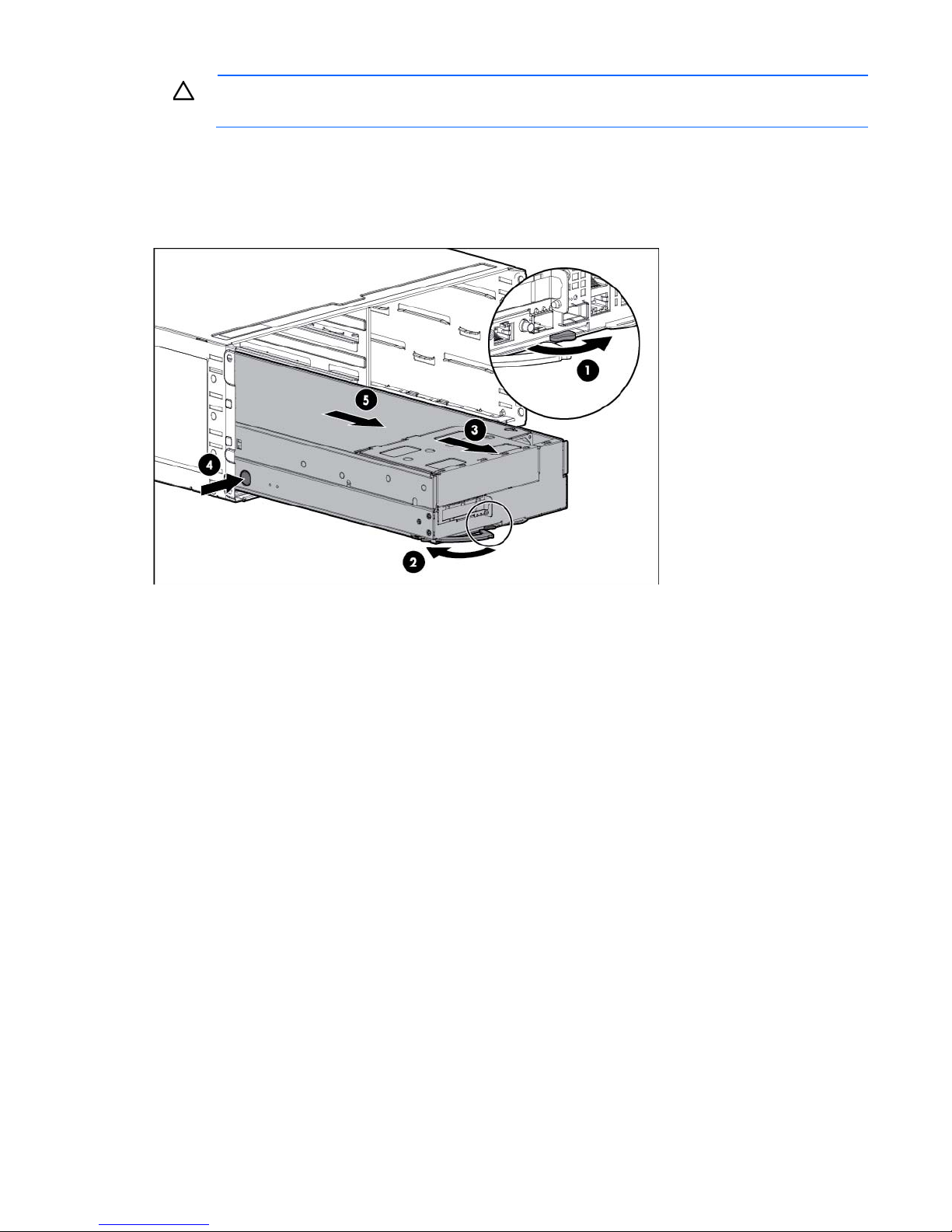
Remove the server from the chassis
1. Power down the server (on page 15).
2. Disconnect all peripheral cables from the server.
Operations 15
CAUTION: To avoid damage to the server, always support the bottom of the server when
removing it from the chassis.
3. Remove the server from the chassis:
a. Press the release button on the front of the server, and then extend the tray handle.
b. Press the release button on the side of the server.
c. Use the tray handle to pull the server out of the chassis.
4. Place the server on a flat, level work surface.
Remove the front GPU cage
1. Power down the server (on page 15).
2. Disconnect all peripheral cables from the server.
3. Remove the server from the chassis (on page 15).
Operations 16
4.
Remove the front GPU cage.
Install the front GPU cage
1. Align the GPU cage with the guiding pins, and then tighten the thumbscrews.
o Left node
Operations 17
o
Right node
2. Install the server into the chassis ("Installing the server into the chassis" on page 31).
3. Connect all peripheral cables to the server.
4. Power up the server (on page 15).
Remove the interposer board
1. Power down the server (on page 15).
2. Disconnect all peripheral cables from the server.
3. Remove the server from the chassis (on page 15).
4. Remove the front GPU cage (on page 16).
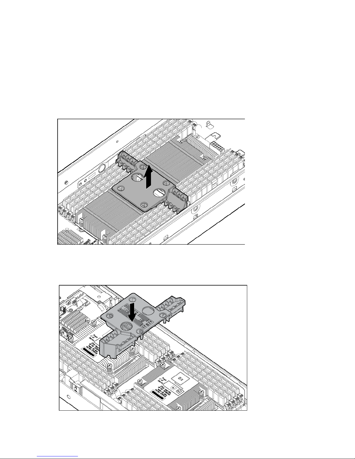
5. Remove the interposer board.
Operations 18
Install the interposer board
1. Install the interposer board.
2. Install the front GPU cage (on page 17).
3. Install the server into the chassis ("Installing the server into the chassis" on page 31).
4. Connect all peripheral cables to the server.
5. Power up the server (on page 15).
Remove the front GPU bracket
1. Power down the server (on page 15).
2. Disconnect all peripheral cables from the server.
3. Remove the front GPU cage (on page 16).
4. Remove the interposer board (on page 18).
Operations 19
5.
Remove the front GPU bracket.
Install the front GPU bracket
1. Install the front GPU bracket into the server, and then tighten the thumbscrews.
2. Install the interposer board (on page 19).
3. Install the front GPU cage (on page 17).
4. Install the server into the chassis ("Installing the server into the chassis" on page 31).
5. Connect all peripheral cables to the server.
6. Power up the server (on page 15).
Operations 20
Remove the processor air baffle
1. Power down the server (on page 15).
2. Disconnect all peripheral cables from the server.
3. Remove the server from the chassis (on page 15).
4. Remove the front GPU cage (on page 16).
5. Remove the interposer board (on page 18).
6. Remove the front GPU bracket (on page 19).
7. Remove the processor air baffle.
Install the processor air baffle
1. Install the processor air baffle.
Operations 21
IMPORTANT: If the DIMM latches are not fully closed, the baffle will not sit properly.
2. Install the front GPU bracket (on page 20).
3. Install the interposer board (on page 19).
4. Install the front GPU cage (on page 17).
5. Install the server into the chassis ("Installing the server into the chassis" on page 31).
6. Connect all peripheral cables to the server.
7. Power up the server (on page 15).
Removing the SFF hot-plug drive cage
1. Power down the server (on page 15).
2. Disconnect all peripheral cables from the server.
3. Remove the server from the chassis (on page 15).
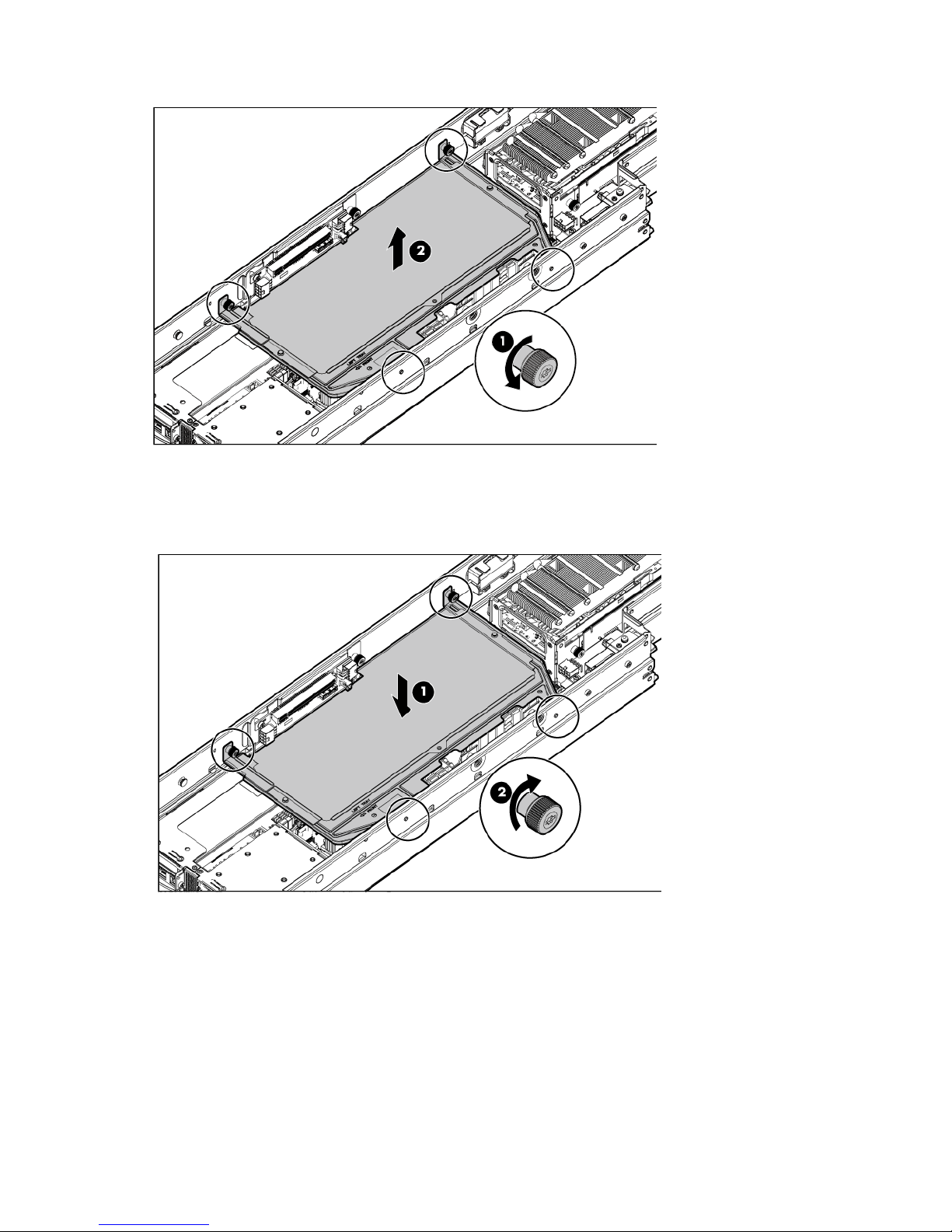
4. Disconnect the drive cables from the drive backplane.
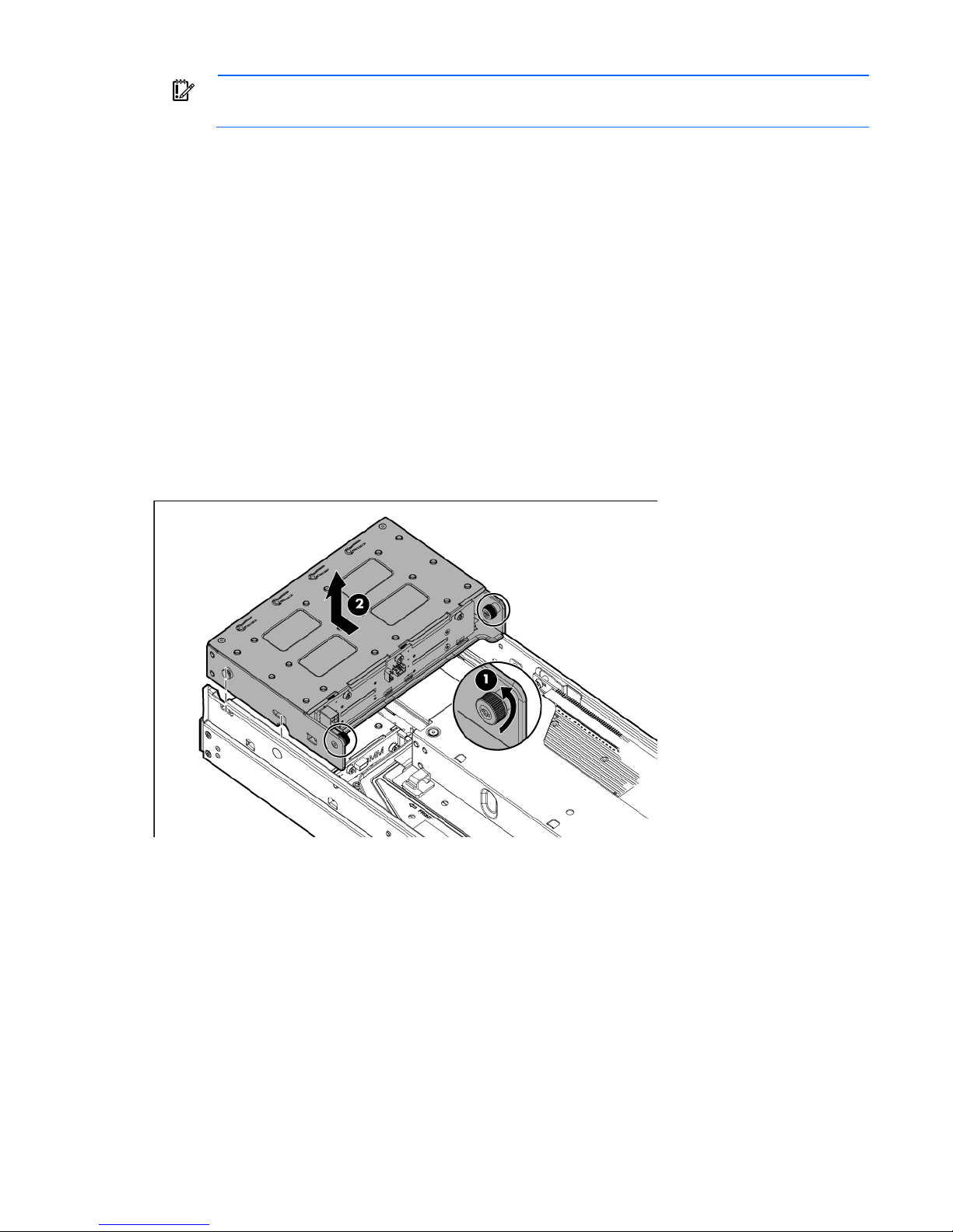
5. Remove the SFF hot-plug drive cage.
Operations 22
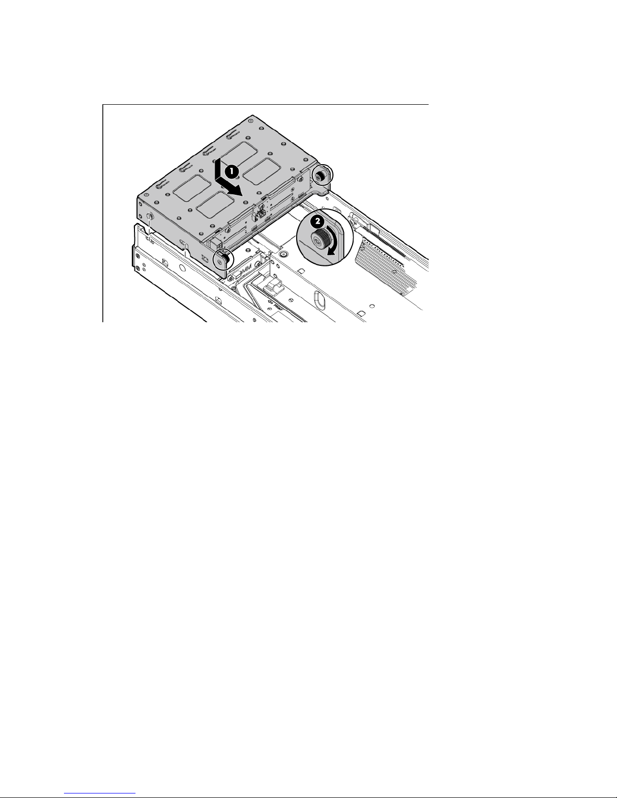
Installing the SFF hot-plug drive cage
1. Install the SFF hot-plug drive cage.
2. Connect the power and Mini-SAS cables to the drive backplane.
3. Install the server into the chassis ("Installing the server into the chassis" on page 31).
4. Connect all peripheral cables to the server.
5. Power up the server (on page 15).
Remove the PCI riser cage
1. Power down the server (on page 15).
2. Disconnect all peripheral cables from the server.
3. Remove the server from the chassis (on page 15).
4. Remove the SFF hot-plug drive cage ("Removing the SFF hot-plug drive cage" on page 22).
5. Remove the front GPU cage (on page 16).
6. Remove the interposer board (on page 18).
7. Remove the front GPU bracket (on page 19).
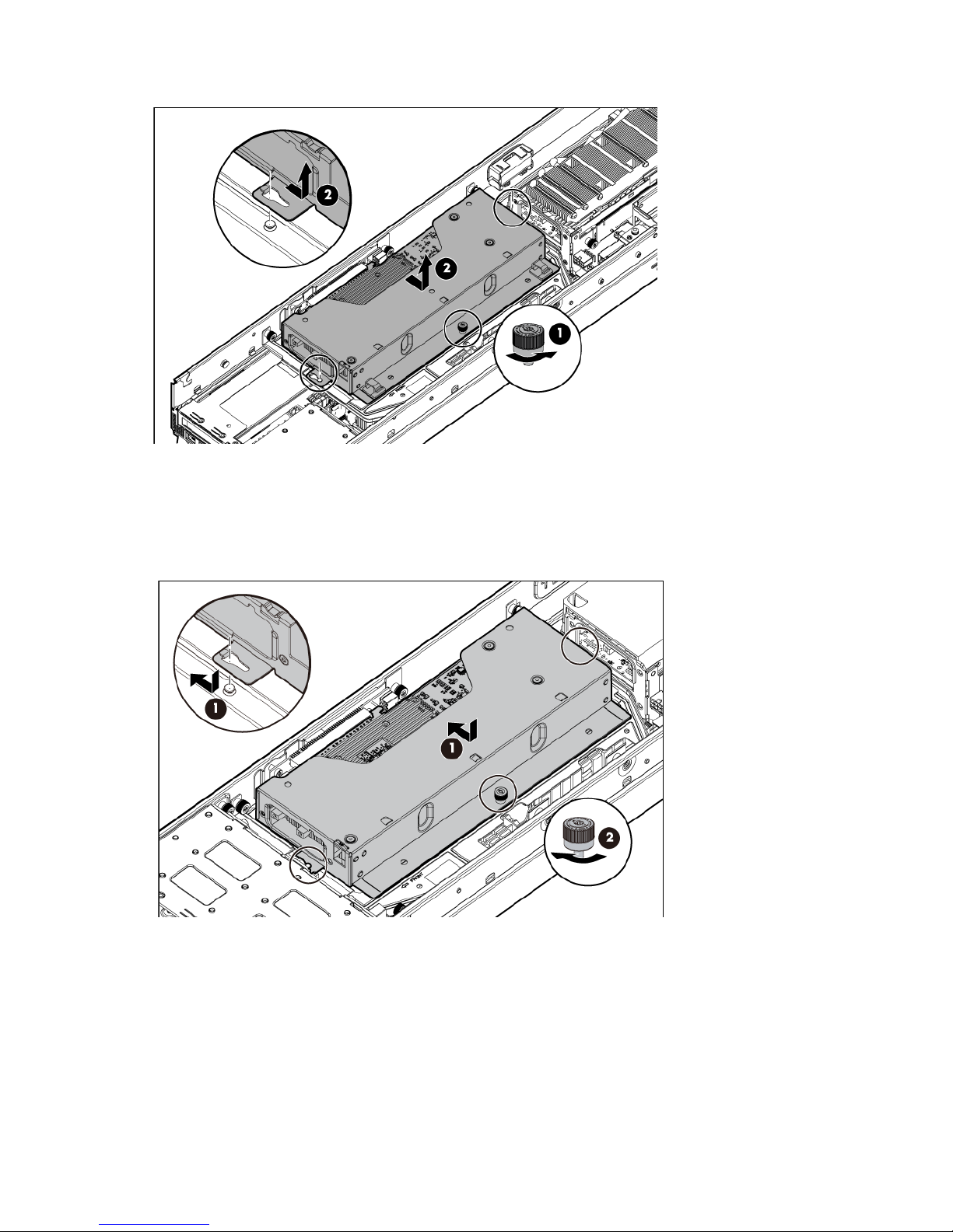
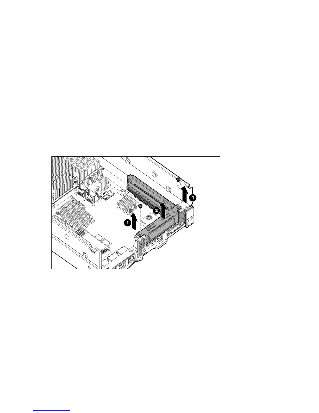
8. Remove the PCI riser cage:
a. Loosen the thumbscrew securing the PCI riser, and then remove the screws securing the PCI riser
cage.
Operations 23
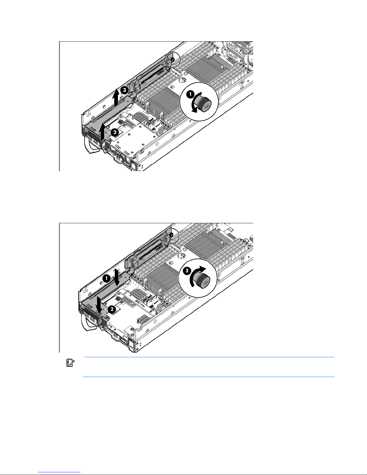
b.
Lift the cage to remove it from the tray.
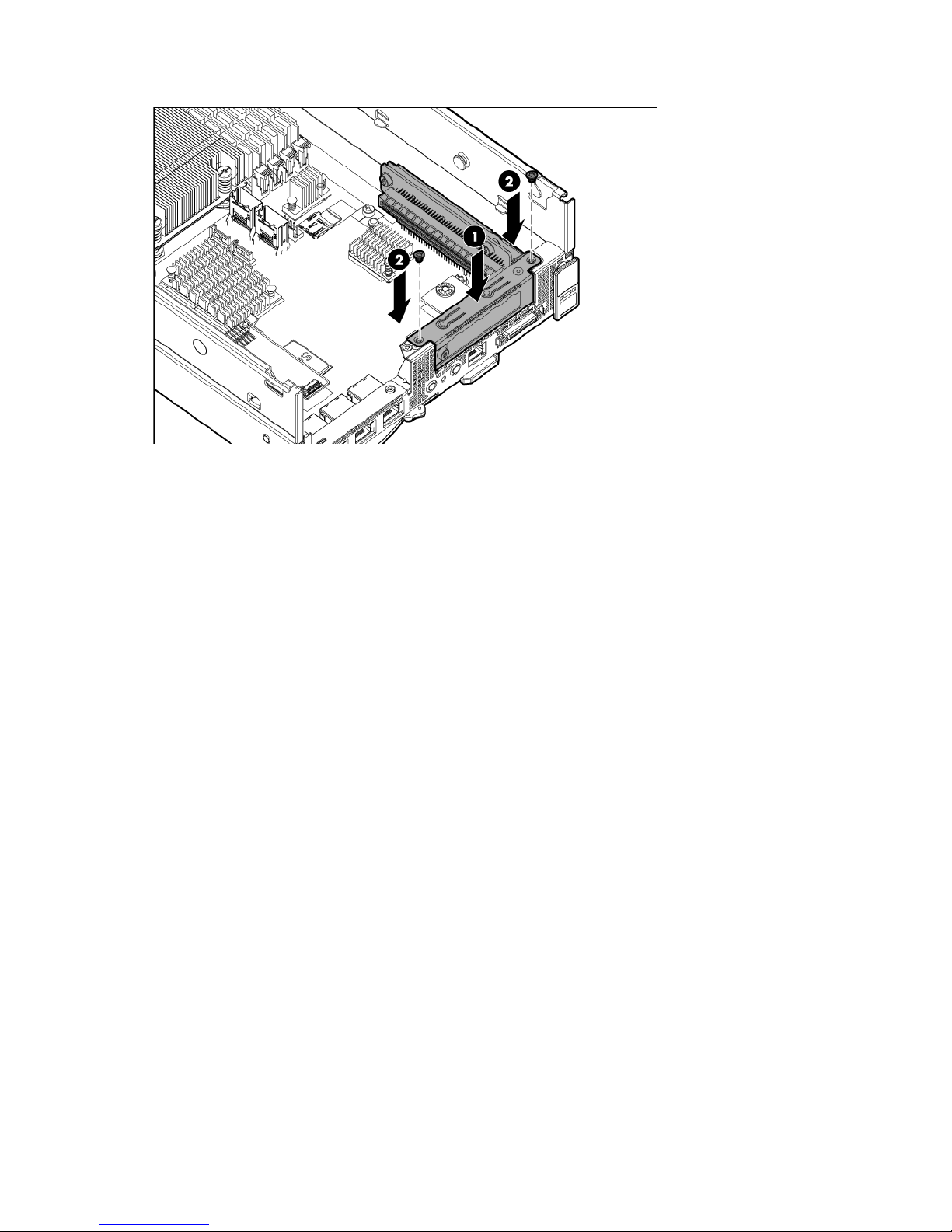
Install the PCI riser cage
1. If necessary, install the expansion boards ("Installing an expansion board" on page 57).
2. Install the PCI riser cage.
IMPORTANT: The server does not power up if the PCI riser cage is not seated properly.
3. Install the front GPU bracket (on page 20).
4. Install the interposer board (on page 19).
5. Install the front GPU cage (on page 17).
6. Install the SFF hot-plug drive cage ("Installing the SFF hot-plug drive cage" on page 23).
7. Install the server into the chassis ("Installing the server into the chassis" on page 31).
Operations 24
8.
Connect all peripheral cables to the server.
9. Power up the server (on page 15).
Remove the FlexibleLOM riser cage
1. Power down the server (on page 15).
2. Disconnect all peripheral cables from the server.
3. Remove the server from the chassis (on page 15).
4. Remove the SFF hot-plug drive cage ("Removing the SFF hot-plug drive cage" on page 22).
5. Remove the front GPU cage (on page 16).
6. Remove the interposer board (on page 18).
7. Remove the front GPU bracket (on page 19).
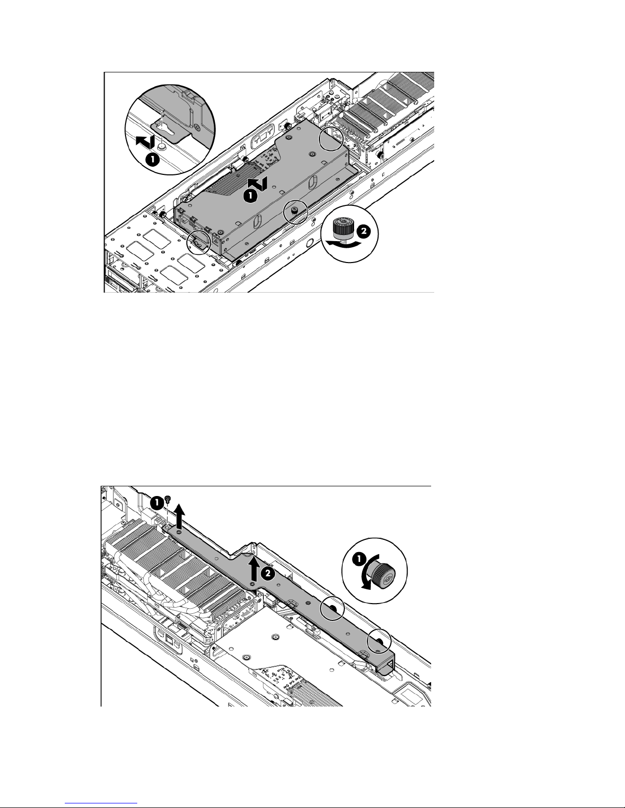
8. Remove the FlexibleLOM riser cage:
a. Remove the screws securing the FlexibleLOM riser cage.
b. Lift the cage to remove it from the tray.
Install the FlexibleLOM riser cage
1. If necessary, install the FlexibleLOM ("Installing an expansion board" on page 57).
Operations 25
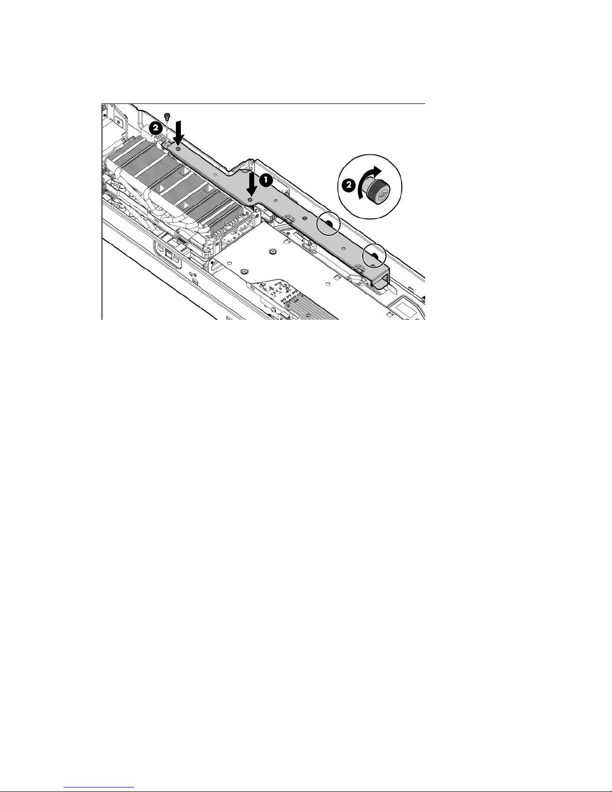
2.
Install the FlexibleLOM riser cage.
3. Install the front GPU bracket (on page 20).
4. Install the interposer board (on page 19).
5. Install the front GPU cage (on page 17).
6. Install the SFF hot-plug drive cage ("Installing the SFF hot-plug drive cage" on page 23).
7. Install the server into the chassis ("Installing the server into the chassis" on page 31).
8. Connect all peripheral cables to the server.
9. Power up the server (on page 15).
Operations 26

Setup
Optional installation services
Delivered by experienced, certified engineers, HP Care Pack services help you keep your servers up and
running with support packages tailored specifically for HP ProLiant systems. HP Care Packs let you integrate
both hardware and software support into a single package. A number of service level options are available
to meet your needs.
HP Care Pack Services offer upgraded service levels to expand your standard product warranty with
easy-to-buy, easy-to-use support packages that help you make the most of your server investments. Some of
the Care Pack services are:
• Hardware support
o 6-Hour Call-to-Repair
o 4-Hour 24x7 Same Day
o 4-Hour Same Business Day
• Software support
o Microsoft®
o Linux
o HP ProLiant Essentials (HP SIM and RDP)
o VMware
• Integrated hardware and software support
o Critical Service
o Proactive 24
o Support Plus
o Support Plus 24
• Startup and implementation services for both hardware and software
For more information on HP Care Pack Services, see the HP website
(http://www.hp.com/services/carepack).
Optimum environment
When installing the server in a rack, select a location that meets the environmental standards described in
this section.
Space and airflow requirements
To allow for servicing and adequate airflow, observe the following space and airflow requirements when
deciding where to install a rack:
Setup 27

party rack is used, observe the following additional requirements to ensure
• Leave a minimum clearance of 63.5 cm (25 in) in front of the rack.
• Leave a minimum clearance of 76.2 cm (30 in) behind the rack.
• Leave a minimum clearance of 121.9 cm (48 in) from the back of the rack to the back of another rack
or row of racks.
HP servers draw in cool air through the front door and expel warm air through the rear door. Therefore, the
front and rear rack doors must be adequately ventilated to allow ambient room air to enter the cabinet, and
the rear door must be adequately ventilated to allow the warm air to escape from the cabinet.
CAUTION: To prevent improper cooling and damage to the equipment, do not block the
When vertical space in the rack is not filled by a server or rack component, the gaps between the
components cause changes in airflow through the rack and across the servers. Cover all gaps with blanking
panels to maintain proper airflow.
The 9000 and 10000 Series Racks provide proper server cooling from flow-through perforations in the front
and rear doors that provide 64 percent open area for ventilation.
ventilation openings.
CAUTION: Always use blanking panels to fill empty vertical spaces in the rack. This arrangement
ensures proper airflow. Using a rack without blanking panels results in improper cooling that can
lead to thermal damage.
CAUTION: When using a Compaq branded 7000 series rack, install the high airflow rack door
insert (PN 327281-B21 for 42U rack, PN 157847-B21 for 22U rack) to provide proper
front-to-back airflow and cooling.
CAUTION: If a third-
adequate airflow and to prevent damage to the equipment:
• Front and rear doors—If the 42U rack includes closing front and rear doors, you must allow
5,350 sq cm (830 sq in) of holes evenly distributed from top to bottom to permit adequate
airflow (equivalent to the required 64 percent open area for ventilation).
• Side—The clearance between the installed rack component and the side panels of the rack
must be a minimum of 7 cm (2.75 in).
Temperature requirements
To ensure continued safe and reliable equipment operation, install or position the system in a well-ventilated,
climate-controlled environment.
The maximum recommended ambient operating temperature (TMRA) for most server products is 35°C
(95°F). The temperature in the room where the rack is located must not exceed 35°C (95°F).
CAUTION: To reduce the risk of damage to the equipment when installing third-party options:
• Do not permit optional equipment to impede airflow around the server or to increase the
internal rack temperature beyond the maximum allowable limits.
• Do not exceed the manufacturer’s TMRA.
Setup 28

Power requirements
Installation of this equipment must comply with local and regional electrical regulations governing the
installation of information technology equipment by licensed electricians. This equipment is designed to
operate in installations covered by NFPA 70, 1999 Edition (National Electric Code) and NFPA-75, 1992
(code for Protection of Electronic Computer/Data Processing Equipment). For electrical power ratings on
options, refer to the product rating label or the user documentation supplied with that option.
WARNING: To reduce the risk of personal injury, fire, or damage to the equipment, do not
overload the AC supply branch circuit that provides power to the rack. Consult the electrical
When installing more than one server, you might need to use additional power distribution devices to safely
provide power to all devices. Observe the following guidelines:
• Balance the server power load between available AC supply branch circuits.
• Do not allow the overall system AC current load to exceed 80% of the branch circuit AC current rating.
authority having jurisdiction over wiring and installation requirements of your facility.
CAUTION: Protect the server from power fluctuations and temporary interruptions with a
regulating uninterruptible power supply. This device protects the hardware from damage caused
by power surges and voltage spikes and keeps the system in operation during a power failure.
• Do not use common power outlet strips for this equipment.
• Provide a separate electrical circuit for the server.
For more information on the hot-plug power supply and calculators to determine server power consumption
in various system configurations, see the HP Power Advisor website
(http://www.hp.com/go/hppoweradvisor).
Electrical grounding requirements
The server must be grounded properly for proper operation and safety. In the United States, you must install
the equipment in accordance with NFPA 70, 1999 Edition (National Electric Code), Article 250, as well as
any local and regional building codes. In Canada, you must install the equipment in accordance with
Canadian Standards Association, CSA C22.1, Canadian Electrical Code. In all other countries, you must
install the equipment in accordance with any regional or national electrical wiring codes, such as the
International Electrotechnical Commission (IEC) Code 364, parts 1 through 7. Furthermore, you must be sure
that all power distribution devices used in the installation, such as branch wiring and receptacles, are listed
or certified grounding-type devices.
Because of the high ground-leakage currents associated with multiple servers connected to the same power
source, HP recommends the use of a PDU that is either permanently wired to the building’s branch circuit or
includes a nondetachable cord that is wired to an industrial-style plug. NEMA locking-style plugs or those
complying with IEC 60309 are considered suitable for this purpose. Using common power outlet strips for
the server is not recommended.
Rack warnings
Setup 29

WARNING: To reduce the risk of personal injury or damage to the equipment, be sure that:
• The leveling jacks are extended to the floor.
• The full weight of the rack rests on the leveling jacks.
• The stabilizing feet are attached to the rack if it is a single-rack installation.
• The racks are coupled together in multiple-rack installations.
• Only one component is extended at a time. A rack may become unstable if more than one
component is extended for any reason.
WARNING: To reduce the risk of personal injury or equipment damage when unloading a rack:
• At least two people are needed to safely unload the rack from the pallet. An empty 42U rack
can weigh as much as 115 kg (253 lb), can stand more than 2.1 m (7 ft) tall, and might
become unstable when being moved on its casters.
• Never stand in front of the rack when it is rolling down the ramp from the pallet. Always handle
the rack from both sides.
Contents of the server shipping carton
Unpack the server shipping carton and locate the materials and documentation necessary for installing the
server. All the rack mounting hardware necessary for installing the server into the rack is included with the
rack or the server.
The contents of the server shipping carton include:
• Server
• Power cord
• Printed setup documentation and software products
• Rack mounting hardware kit and documentation
In addition to these supplied items, you might need:
• T-10/T-15 Torx screwdriver
• Hardware options
• Operating system or application software
Installing the chassis
The chassis can be installed either in a rack or rack-free environment. For rack installations, install the rack
rails, and then install the chassis and other components.
For more information, see the HP ProLiant s6500 Chassis Setup and Installation Guide, Quick Deploy Rail
System Installation Instructions that ship with the rack hardware kit, and applicable installation instructions.
Installing options
Install any hardware options before initializing the server. For options installation information, see the
documentation that ships with the option. For server-specific information, see the server user guide on the HP
website (http://www.hp.com).
Setup 30
 Loading...