

HP ProLiant s6500 Chassis, ProLiant s6500 Setup And Installation Manual

HP ProLiant s6500 Chassis
This guide describes the setup, configuration, and usage of the HP ProLiant s6500 Chassis.
Setup and Installation Guide
Abstract
Part Number: 653239-005
June 2014
Edition: 5

© Copyright 2011, 2014 Hewlett-Packard Development Company, L.P.
The information contained herein is subject to change without notice. The only warranties for HP products and services are set forth in the express
warranty statements accompanying such products and services. Nothing herein should be construed as constituting an additional warranty. HP shall
not be liable for technical or editorial errors or omissions contained herein.
Microsoft® is a U.S. registered trademark of Microsoft Corporation.

Contents
Planning the installation ................................................................................................................. 5
Features ...................................................................................................................................................... 5
Grounding requirements ............................................................................................................................... 5
Space and airflow requirements .................................................................................................................... 5
Configuration rules ....................................................................................................................................... 6
Identifying components and LEDs .................................................................................................... 7
Front panel components ................................................................................................................................ 7
Rear panel components ................................................................................................................................ 7
Rear panel LEDs and buttons ......................................................................................................................... 8
Redundant system fan configuration ............................................................................................................... 9
Installing components .................................................................................................................. 10
System fans ............................................................................................................................................... 10
Removing the system fan ................................................................................................................... 10
Installing the system fan .................................................................................................................... 11
Power supplies ........................................................................................................................................... 11
Removing the PSU backplane ............................................................................................................ 12
Installing the PSU backplane ............................................................................................................. 13
Removing the power supply............................................................................................................... 14
Installing the power supply ................................................................................................................ 14
Rack options .............................................................................................................................................. 16
Installing the 4U rack kit.................................................................................................................... 16
Installing the 4U POD rail kit ............................................................................................................. 18
Installing the 4U third-party rail kit ...................................................................................................... 21
Installing the chassis handles kit ......................................................................................................... 23
Installing the half-width node blank .............................................................................................................. 24
Installing the full-width node blank ............................................................................................................... 25
Removing the center wall ............................................................................................................................ 25
Cabling ..................................................................................................................................... 27
Hardware installation ................................................................................................................................. 27
Scalable system hardware ................................................................................................................ 27
Rack types and configurations ........................................................................................................... 27
Optional installation services ............................................................................................................. 28
Optimum environment....................................................................................................................... 29
Installation guidelines ....................................................................................................................... 30
Cabling guidelines ........................................................................................................................... 31
Installation overview for full-rack solutions ........................................................................................... 31
Power cabling............................................................................................................................................ 32
Power requirements and considerations .............................................................................................. 32
PDU support .................................................................................................................................... 33
Extension bar support ....................................................................................................................... 33
Power cabling configurations ............................................................................................................ 33
Network cabling ........................................................................................................................................ 41
Network adapter and switch support.................................................................................................. 41
Network cabling configurations ......................................................................................................... 41
Contents 3

Using the HP Advanced Power Manager ....................................................................................... 44
HP APM overview ...................................................................................................................................... 44
Best practices ............................................................................................................................. 45
Three-phase balancing ................................................................................................................................ 45
3+1 redundant mode and 4 single-ended nonredundant mode ....................................................................... 46
Support and other resources ........................................................................................................ 47
Before you contact HP ................................................................................................................................ 47
HP contact information ................................................................................................................................ 47
Acronyms and abbreviations ........................................................................................................ 48
Documentation feedback ............................................................................................................. 50
Index ......................................................................................................................................... 51
Contents 4

Planning the installation
Features
The HP ProLiant SL chassis can accommodate up to eight half-width servers, giving you the ability to mix and
match server nodes, and also allows for single node serviceability.
The ProLiant SL Chassis includes the following features:
• Right-sized HP ProLiant power supplies from 750 W at 94% efficiency to 1200 W at 94% efficiency
• Supports up to four full-width servers
• Supports hot plug redundant or non redundant fans
• Ability to mix and match half-width server trays in one chassis
• Single node serviceability enables you to serve one tray while the other trays continue to operate
• Uses shared power and cooling for better efficiency
• Three-phase power balancing
• Hot-plug serviceable fans and power supplies
NOTE: Half-width and full-width server trays cannot be mixed within a chassis.
Grounding requirements
• The building installation must provide a means of connection to protective earth.
• The equipment must be connected to that means of connection.
• A service person must check whether the socket-outlet from which the equipment is to be powered
provides a connection to the building protective earth. If the outlet does not provide a connection, the
service person must arrange for the installation of a protective earthing conductor from the separate
protective earthing terminal to the protective earth wire in the building.
Space and airflow requirements
To allow for servicing and adequate airflow, observe the following space and airflow requirements when
deciding where to install a rack:
• Leave a minimum clearance of 63.5 cm (25 in) in front of the rack.
• Leave a minimum clearance of 76.2 cm (30 in) behind the rack.
• Leave a minimum clearance of 121.9 cm (48 in) from the back of the rack to the back of another rack
or row of racks.
Planning the installation 5
HP servers draw in cool air through the front door and expel warm air through the rear door. Therefore, the
front and rear rack doors must be adequately ventilated to allow ambient room air to enter the cabinet, and
the rear door must be adequately ventilated to allow the warm air to escape from the cabinet.
CAUTION: To prevent improper cooling and damage to the equipment, do not block the
ventilation openings.
When vertical space in the rack is not filled by a server or rack component, the gaps between the
components cause changes in airflow through the rack and across the servers. Cover all gaps with blanking
panels to maintain proper airflow.
CAUTION: Always use blanking panels to fill empty vertical spaces in the rack. This arrangement
ensures proper airflow. Using a rack without blanking panels results in improper cooling that can
lead to thermal damage.
The 9000 and 10000 Series Racks provide proper server cooling from flow-through perforations in the front
and rear doors that provide 64 percent open area for ventilation.
CAUTION: When using a Compaq branded 7000 series rack, install the high airflow rack door
insert (PN 327281-B21 for 42U rack, PN 157847-B21 for 22U rack) to provide proper
front-to-back airflow and cooling.
CAUTION: If a third-party rack is used, observe the following additional requirements to ensure
adequate airflow and to prevent damage to the equipment:
• Front and rear doors—If the 42U rack includes closing front and rear doors, you must allow
5,350 sq cm (830 sq in) of holes evenly distributed from top to bottom to permit adequate
airflow (equivalent to the required 64 percent open area for ventilation).
• Side—The clearance between the installed rack component and the side panels of the rack
must be a minimum of 7 cm (2.75 in).
Configuration rules
• Half-width and full-width trays cannot be mixed.
• No 2U trays can reside in the middle two bays.
• Each half of the chassis can support any of the half-chassis configurations.
• All SL-series servers can be mixed.
• Empty bays must be populated with a node blank to meet thermal requirements.
• Fans must be installed in all fan bays to meet thermal requirements.
• Redundant and nonredundant fan configurations cannot be mixed.
Planning the installation 6
Identifying components and LEDs
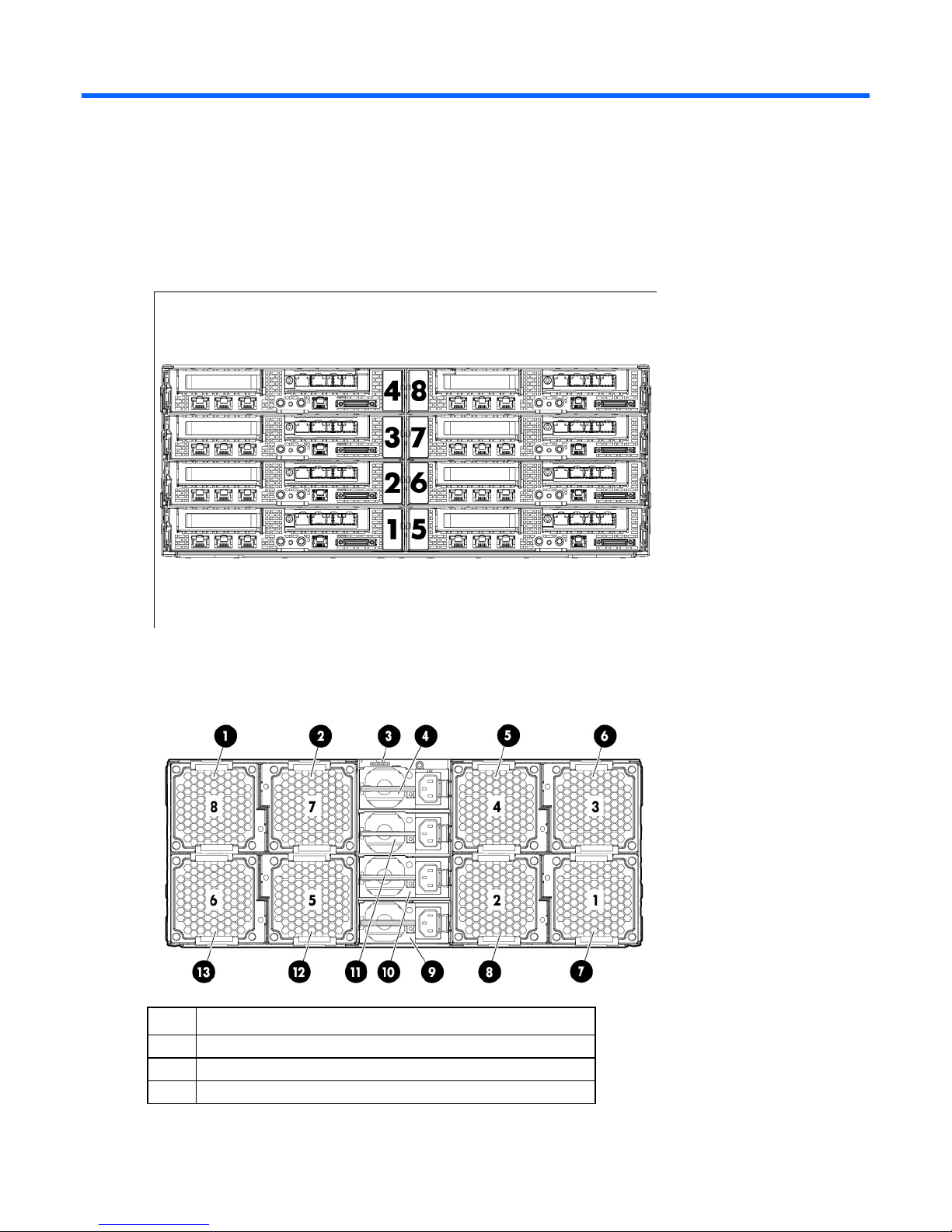
Front panel components
The following figure identifies the slot numbering for the front panel of the s6500 chassis.
Rear panel components
Item Description
1
2
3
Fan 8
Fan 7
HP APM interface
Identifying components and LEDs 7
11
4
5
6
7
8
9
10
Power supply 4
Fan 4
Fan 3
Fan 1
Fan 2
Power supply 1
Power supply 2
Power supply 3
12
13
Fan 5
Fan 6
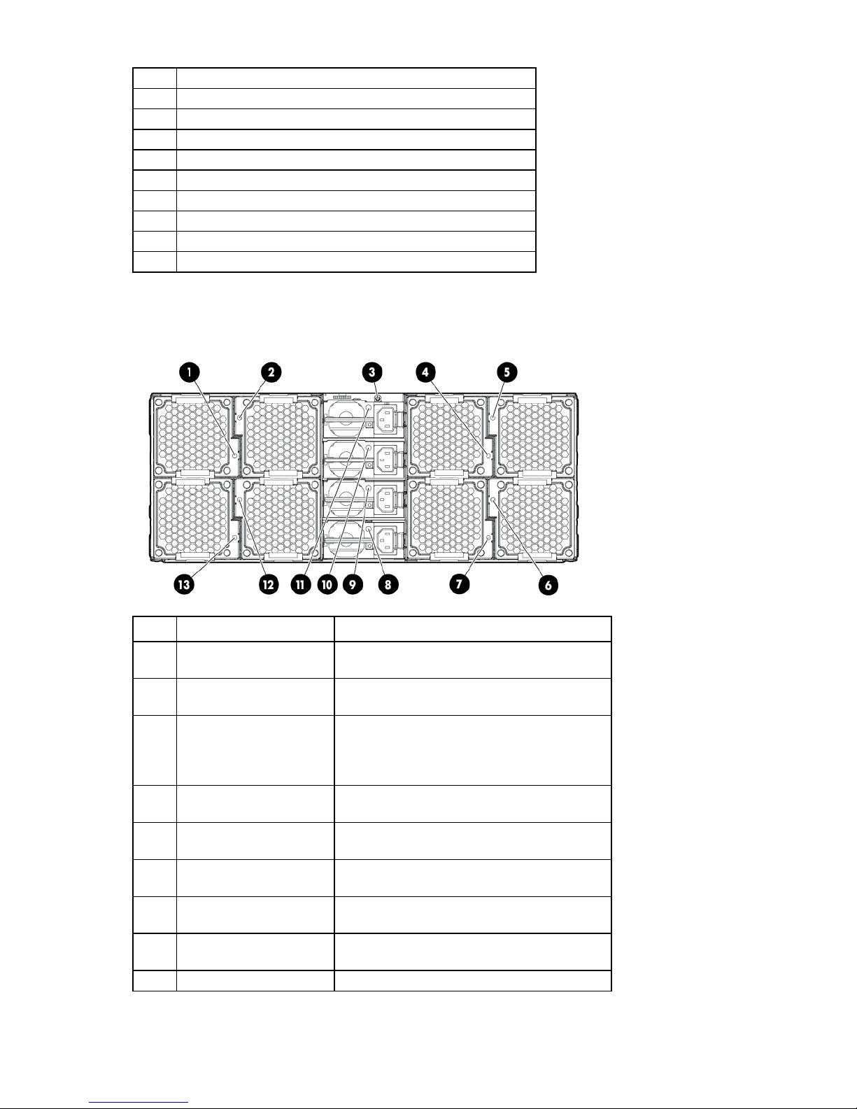
Rear panel LEDs and buttons
Item Description Status
1
2
3
4
5
6
7
8
9
Fan 8/16 power LED Off—Normal
Amber—Fan has failed.
Fan 7/15 power LED Off—Normal
Amber—Fan has failed.
UID LED button Blue—Activated
Flashing blue—System is being remotely
managed.
Off—Deactivated
Fan 4/12 power LED Off—Normal
Amber—Fan has failed.
Fan 3/11 power LED Off—Normal
Amber—Fan has failed.
Fan 1/9 power LED Off—Normal
Amber—Fan has failed.
Fan 2/10 power LED Off—Normal
Amber—Fan has failed.
Power supply 1 power LED Green—Normal
Off—No AC power
Power supply 2 power LED Green—Normal
Identifying components and LEDs 8
Item Description Status
Off—No AC power
10
11
12
13
Power supply 3 power LED Green—Normal
Off—No AC power
Power supply 4 power LED Green—Normal
Off—No AC power
Fan 5/13 power LED Off—Normal
Amber—Fan has failed.
Fan 6/14 power LED Off—Normal
Amber—Fan has failed.
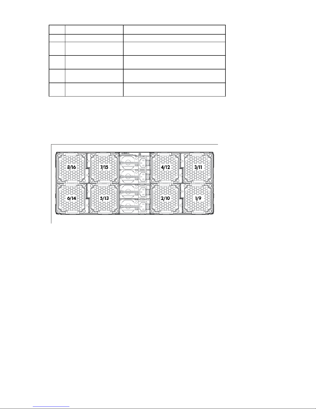
Redundant system fan configuration
The server has 16 system fans located on the rear panel of the chassis.
The following figure identifies the system fans by device number.
Identifying components and LEDs 9
Installing components
System fans
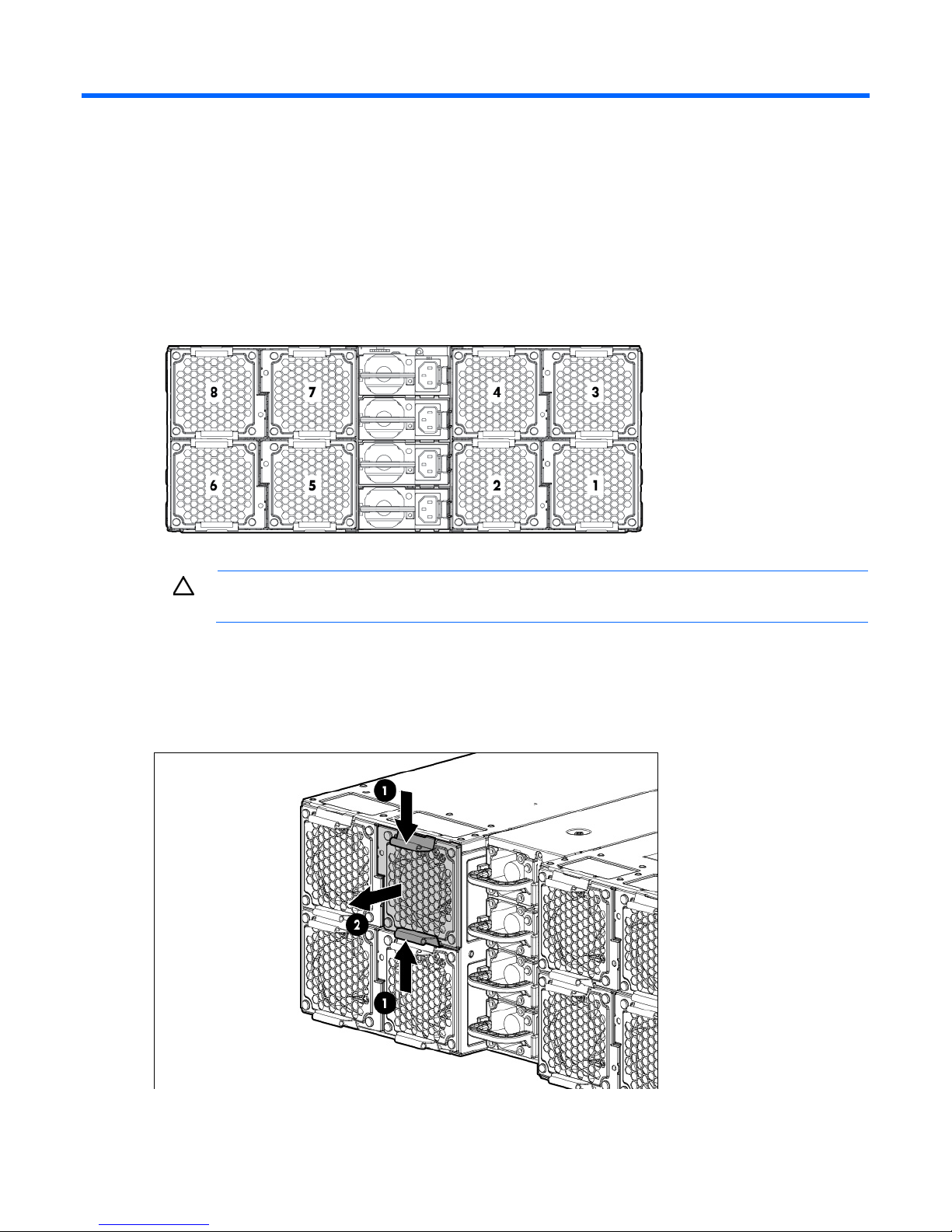
The server has eight system fans located on the rear panel of the chassis.
The following figure identifies the system fans by device number.
CAUTION: To prevent damage to the server, do not install a combination of redundant and
non-redundant fans.
Removing the system fan
1. Squeeze the two release tabs on the system fan together to release it from the chassis.
2. Lift the system fan away from the chassis.
Installing components 10

Installing the system fan
Insert the system fan into the chassis.
Power supplies
Standard 750-W or 1200-W power supplies with PFC functionality are located on the rear panel of the
server.
NOTE: Power supplies with different wattage cannot be mixed in the same chassis.
Item Description
1
2
3
4
Power supply 4
Power supply 3
Power supply 2
Power supply 1
Installing components 11
Removing the PSU backplane
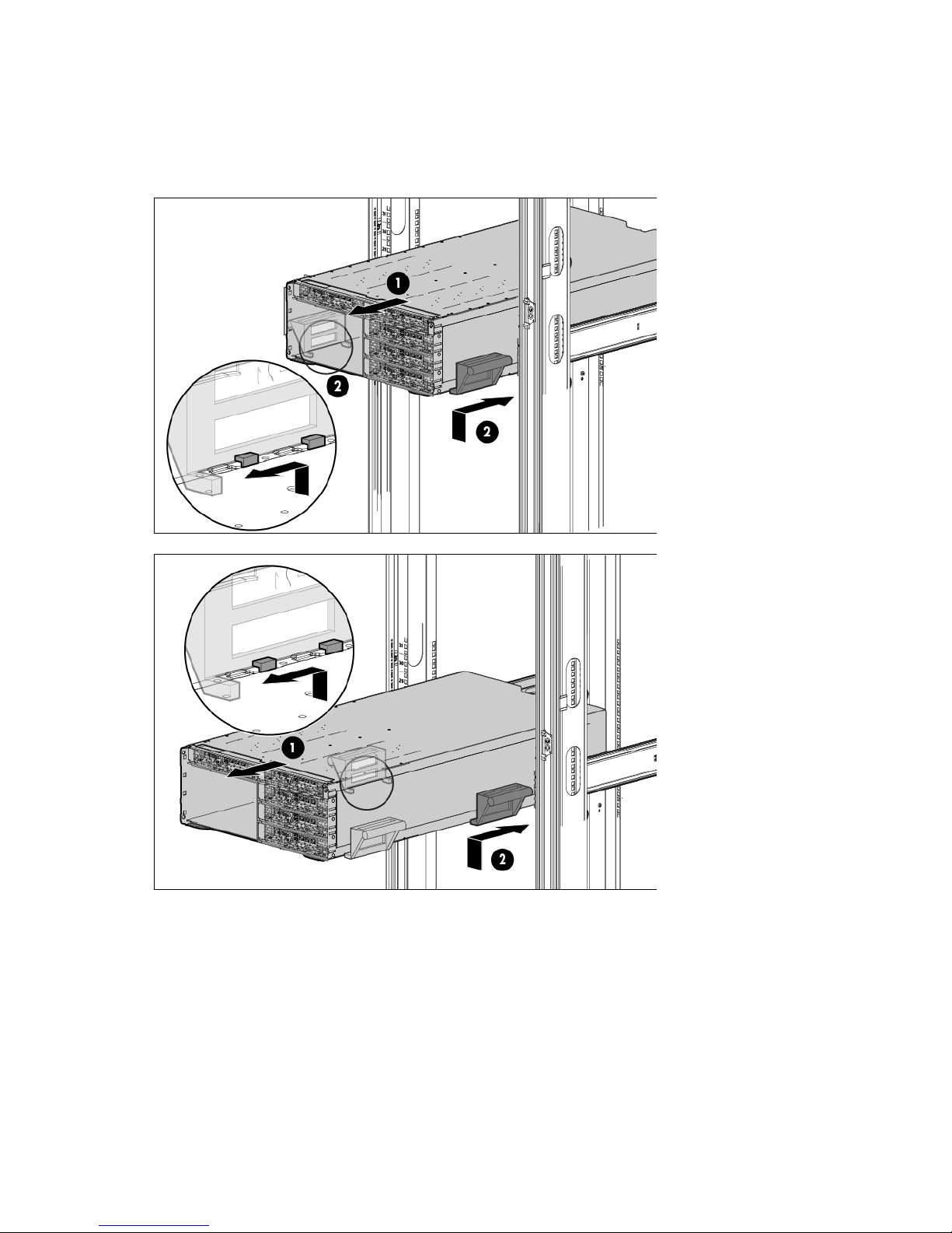
1. To reduce weight of the chassis, remove the power supplies ("Removing the power supply" on page 14)
and server nodes. For information about removing the nodes, see the server user guide.
2. Pull the chassis out of the rack far enough to install the chassis handles.
3. Use the chassis handles to remove the chassis from the rack.
4. Place the chassis on flat, level surface.
5. Remove the top cover from the power supply cage.
6. Disconnect all cables from the PSU backplane.
Installing components 12
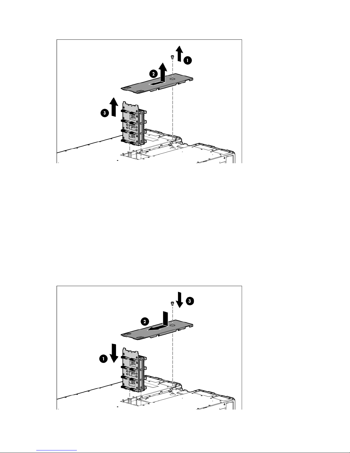
7.
Remove the PSU backplane.
Installing the PSU backplane
1. To reduce weight of the chassis, remove the power supplies ("Removing the power supply" on page 14)
and server nodes. For information about removing the nodes, see the server user guide.
2. Pull the chassis out of the rack far enough to install the chassis handles.
3. Use the chassis handles to remove the chassis from the rack.
4. Place the chassis on flat, level surface.
5. Remove the top cover from the power supply cage.
6. Unplug all cables from the chassis.
7. Install the PSU backplane.
8. Connect all cables to the PSU backplane.
9. Install the top cover to the power supply cage.
Installing components 13
10.
Install the chassis in the rack.
11. Install the nodes and power supplies.
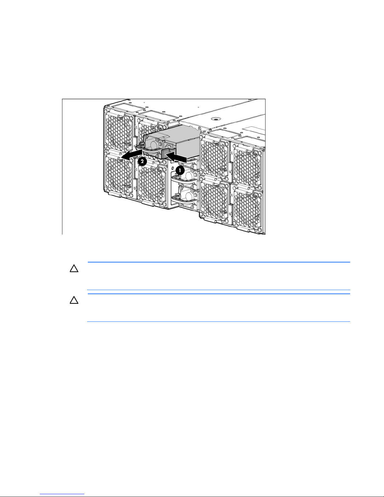
Removing the power supply
1. Press the port colored button on the power supply latch.
2. Slide the power supply out of the power supply bay.
Installing the power supply
CAUTION: Always install either a hot-plug power supply or a power supply blank into each bay
to maintain proper airflow and cooling in the server. Improper airflow can lead to thermal
1. Align the power supply edge card connector with the open slot of power supply cage.
damage.
CAUTION: Do not mix HP 1200W, HP 1200W High Efficiency, HP 750W, or HP 750W High
Efficiency power supplies in one enclosure. Install only one type of power supply in a single
enclosure.
Installing components 14
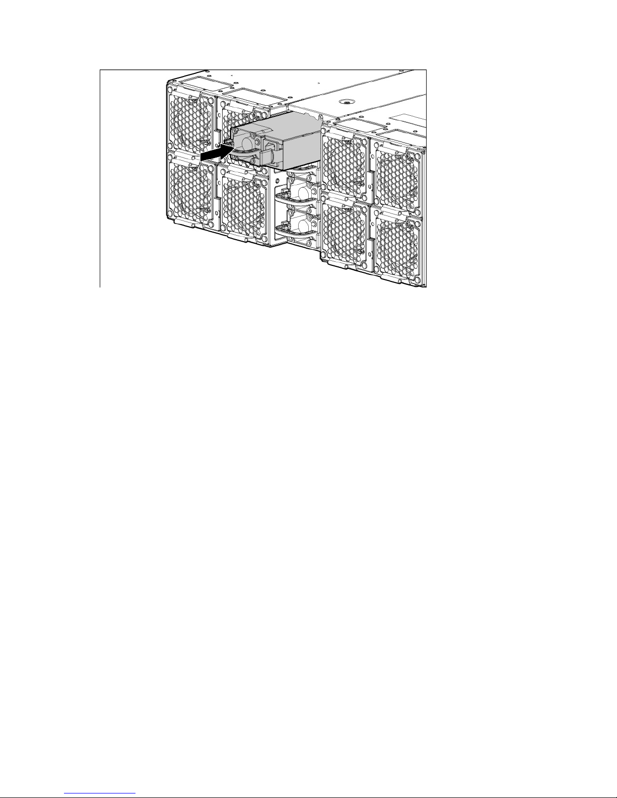
2.
Slide the power supply into the power supply bay until it clicks into place.
Installing components 15
Rack options
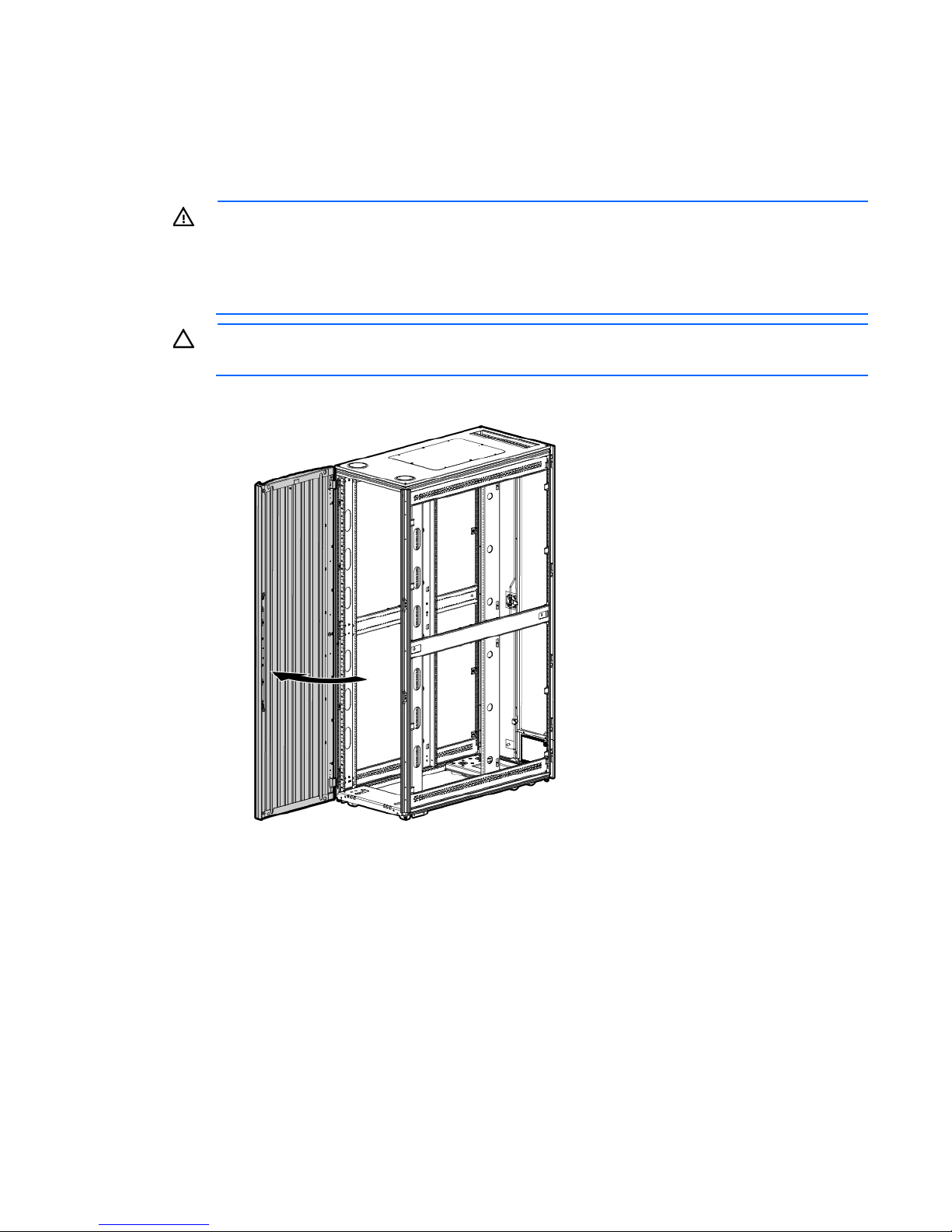
Installing the 4U rack kit
WARNING: The server is very heavy. To reduce the risk of personal injury or damage to the
equipment:
• Reduce the weight of the server by removing the hard drives and power supplies before
installing the server into the rack.
Before installing the rail kit, release the handle and open the door.
• At least two people are required to lift the server during installation or removal.
CAUTION: Always plan the rack installation so that the heaviest item is on the bottom of the rack.
Install the heaviest item first, and continue to populate the rack from the bottom to the top.
1. Insert the rail in the rack column.
2. Insert the two middle standoffs on the rail into the holes on the front rack column.
3. To secure the front of the rail to the front rack column, fasten the shoulder screws.
Installing components 16
 Loading...