

Page 1

HP ProLiant Power Interface Control (PPIC) Utility
Part Number: 583301-005
User Guide
Abstract
This guide is for HP ProLiant SL customers and Firmware installers. This guide describes chassis/rack architecture, power management, control
utilities, and command and options descriptions for select HP ProLiant servers.
March 2011
Edition: 5
Page 2

© Copyright 2009, 2011 Hewlett-Packard Development Company, L.P.
The information contained herein is subject to change without notice. The only warranties for HP products and services are set forth in the express
warranty statements accompanying such products and services. Nothing herein should be construed as constituting an additional warranty. HP shall
not be liable for technical or editorial errors or omissions contained herein.
Microsoft and Windows Server are U.S. registered trademarks of Microsoft Corporation.
Page 3

Contents
Introduction .................................................................................................................................. 4
New chassis/rack architecture .................................................................................................................... 4
Power Management Controller .................................................................................................................... 4
Power Measurement ...................................................................................................................... 5
Power Measurement .................................................................................................................................. 5
Commands description .................................................................................................................. 6
Help menu ............................................................................................................................................... 6
Display chassis power level and configuration .............................................................................................. 6
Poll chassis power level .............................................................................................................................. 6
Verbose ................................................................................................................................................... 6
Calibrate and display power limits .............................................................................................................. 7
Set power configuration mode .................................................................................................................... 7
HP ProLiant Power Interface Control (PPIC) Utility .............................................................................. 9
Command line utility .................................................................................................................................. 9
Supported OSs ......................................................................................................................................... 9
Synopsis .................................................................................................................................................. 9
Options description ................................................................................................................................... 9
Select communication bus ................................................................................................................. 9
Select output log filename ................................................................................................................. 9
Configuration examples ............................................................................................................................. 9
Contents 3
Page 4
Introduction
New chassis/rack architecture
The new line of HP ProLiant s6500 Scalable Server, HP ProLiant DL1000/DL2000 Multi-Node Server, and
HP ProLiant SL6000 Scalable Servers implement entirely new chassis/ rack architecture in the industry
standard server market space, producing the most power efficient and power manageable servers in the
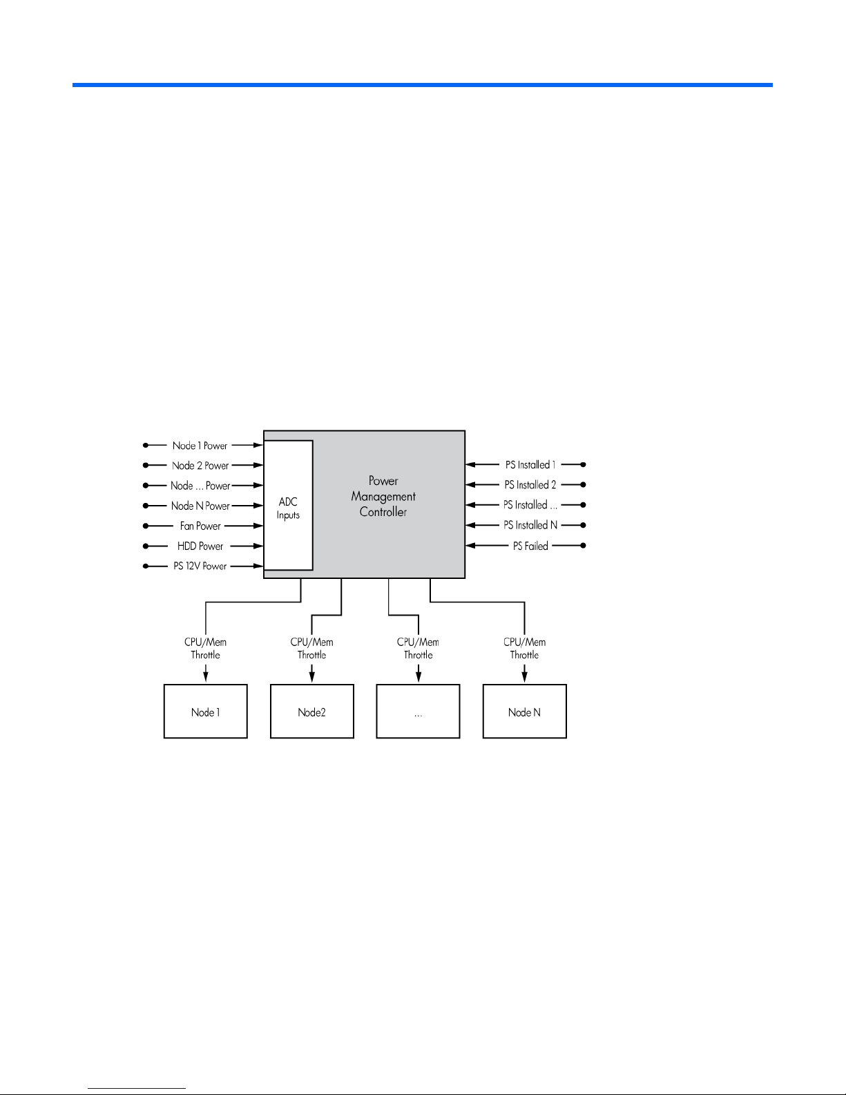
world. Each 2U chassis consists of up to 4 nodes and up to 4 fans. Each 4U chassis consists of up to 8 nodes
and up to 8 fans. Each chassis also contains an embedded microcontroller that provides power metering and
Power Management Controller
throttling capabilities for the entire chassis.
As depicted in the above diagram, the embedded Power Management Controller is able to monitor power
consumption for all aspects of the 2U/4U chassis and throttle the speed of the processors and memory in
each node within the 2U/4U chassis in order to maintain a pre-set power budget.
Introduction 4
Page 5

Power Measurement
Power Measurement
This utility displays the power reading calculated by the chassis Power Management Controller.
As with any measurement system, variations in temperature, input power, and system loads will impact the
accuracy of the power calculations. All power reading displayed by this utility will have a -/+ 5% tolerance.
Power Measurement 5
Page 6

Commands description
PPIC can only process one command at a time.
Help menu
-h:
This command will display a summary of supported commands and options.
Display chassis power level and configuration
-d:
This command will display the instantaneous power reading for the entire chassis:
1. Total Chassis Power (AC): the sum of all power consumed by all present nodes and chassis subsystems.
2. Set Power Configuration Mode for more information.
Poll chassis power level
-p -ffrequency -tduration:
This command will poll the chassis status and configuration every frequency seconds for a total duration of
duration seconds:
1. Total Chassis Power (AC): the sum of all power consumed by all present nodes and chassis subsystems.
Enabling verbose mode (-v) will provide detailed information about the chassis power consumption.
Verbose
-v:
This command will only affect the output of Display chassis power level and configuration and Poll chassis
power level. Enabling verbose will provide detailed information about the chassis power consumption:
1. Maximum Chassis Power Available (AC): the total power supply capacity available in the chassis.
2. Total Chassis Power (AC): the sum of all power consumed by all present nodes and chassis subsystems.
3. Total Chassis Peak Power (AC): the highest calculated power value for the chassis since it was last
cleared.
4. Total Chassis Peak Power (DC): the highest calculated power value for the chassis since it was last
cleared.
5. Bay Power (DC): the instantaneous power consumption calculated at each bay. (Example: A 2U node
connected on bay 3 will have a total power consumption of bay 3 plus bay 4)
6. Total Fan Power (DC): instantaneous fan power consumption of all active fans in the chassis.
Commands description 6
Page 7

7.
When Power Control Configuration Mode is set to User Configurable (3), the system will
No Redundancy
Set Power Configuration Mode for more information.
Calibrate and display power limits
-c:
This command will force the system to idle state to get the lowest possible power configuration. Once the
value has been obtained the system will display the updated information:
1. Maximum Chassis Power Available (AC): the total power supply capacity available in the chassis.
2. Minimum Chassis Power Achieved (AC): the lowest power achieved at idle with the current system
configuration.
3. Power Limits (AC): the power range the Power Control Mode will guarantee full operation.
4. Set Power Configuration Mode for more information.
NOTE: System performance will degrade while acquiring Power Profile.
NOTE:
return to the default Power Control Configuration Mode (1) after system calibration completes.
The user is responsible for setting a new Power Control Configuration Mode and level.
Set power configuration mode
-s -mmode -lpower:
This command will update the chassis Power Control Configuration Mode. The Power Management Control
table shows the valid values for mode. Power is required when setting Power Control Configuration to User
Configurable.
Mode Configuration
0
1
2
3
Power throttling disabled.
AC Redundancy with throttling (Default mode)
This provides Maximum Performance with PS Redundancy. Power control logic will only throttle the
performance of each node in the case where the total power draw by the chassis attempts to exceed
the power supply capacity. In this mode, the box is expected to survive an unexpected AC Power loss
to one of the power supplies.
Full AC/DC Redundancy
Power control logicl maintains a power cap value at the DC rating of a single power supply
(Example: 460W, 750W, or 1200W), such that if one power supply experiences a DC or AC
failure, the chassis remains on-line and operational. User must be cognizant of the minimum power
consumption of the chassis and this must be less than the rating of a single power supply.
User Configurable (Available only with the LO100/iLO Advanced Pack)
User specifies the power envelope for the chassis, within the capabilities of the HW installed. Before
setting this mode, it is required that the user run PPIC's Calibrate and display power limits command
to obtain the minimum and maximum power consumption envelope for the chassis. In order to avoid
punitive performance due to throttling,do not set a User Configurable Power Control Mode limit value
Commands description 7
Page 8

Mode Configuration
When Power Control Configuration Mode is set to User Configurable (3), the system will
below or within 20% of the minimum power value obtained during system calibration.
Recommended steps to properly define the Power Control Configuration level for User Configurable (3) mode:
1.
Run the target system (all nodes in chassis) at the production level load.
2. Calibrate the chassis to obtain the power profile and display the information (ppic -c).
3. Set the Power Control Configuration Level within the specified Power Capping Limit Range obtained in
the step (ppic -s -m3 -lpower, where power is the preferred set point in Watts AC).
4. Verify the chassis power level and configuration enabling verbose mode (ppic -d -v).
5. Monitor chassis power is within 5% of desired power level set point (ppic -p -f1 -t10).
NOTE:
return to the default Power Control Configuration Mode (1) after system calibration completes.
The user is responsible for setting a new Power Control Configuration Mode and level.
Commands description 8
Page 9

HP ProLiant Power Interface Control (PPIC) Utility
Command line utility
HP provides a simple command line utility, called PPIC, for monitoring and configuring the power control
configuration of the SL product lines.
The PPIC utility must only be executed through one server node per chassis.
Supported OSs
Versions of this utility are available for Microsoft Windows Server OS (2008 and 2008 R2) and Linux OS
(RHEL5 and SLES11) with the requirement that the OS IPMI Driver be installed.
Synopsis
ppic [-h] [-d] [-v] [-p -ffrequency -tduration] [-c] [-s -mmode -lpower] [-bbus]
[-ofilename]
Options description
Select communication bus
These options need to be specified with a valid command to be processed.
-bbus:
This option allows overriding the default communication bus to the Power Management Controller. Changing
the default communication bus might prevent PPIC from working properly.
Select output log filename
-ofilename.log:
This option allows overriding the output filename, where filename is the filename and log is the extension. By
default, the screen output is also saved into the ppic.log. Every time this utility is executed, the default log is
overwritten with the latest output.
Configuration examples
Display chassis power level and configuration and store output in power.log file
ppic -d -opower.log
Poll chassis power level every 1s for 10 minutes and enable verbose mode
ppic -p -f1 -t600 -v
HP ProLiant Power Interface Control (PPIC) Utility 9
Page 10

Set Power Configuration Mode to AC Redundancy with throttling (Default Mode) and store output in
config.log
ppic -s -m1 -oconfig.log
HP ProLiant Power Interface Control (PPIC) Utility 10
 Loading...