

Page 1

HP ProLiant ML570 Generation 2 Server
Maintenance and Service Guide
January 2004 (Fifth Edition)
Part Number 223958-005
Page 2

© 2002, 2004 Hewlett-Packard Development Company, L.P.
Microsoft, Windows, and Windows NT are U.S. registered trademarks of Microsoft Corporation.
Intel and Xeon are trademarks or registered trademarks of Intel Corporation or its subsidiaries in the United States
and other countries.
Hewlett-Packard Company shall not be liable for technical or editorial errors or omissions contained herein. The
information in this document is provided “as is” without warranty of any kind and is subject to change without
notice. The warranties for HP products are set forth in the express limited warranty statements accompanying such
products. Nothing herein should be construed as constituting an additional warranty.
HP ProLiant ML570 Generation 2 Server Maintenance and Service Guide
January 2004 (Fifth Edition)
Part Number 223958-005
Page 3

Contents
About This Guide
Audience Assumptions............................................................................................................................... vii
Technician Notes........................................................................................................................................ vii
Where to Go for Additional Help.............................................................................................................. viii
Integrated Management Log............................................................................................................... viii
Telephone Numbers............................................................................................................................ viii
Chapter 1
Illustrated Parts Catalog
Chassis Components Exploded View........................................................................................................ 1-2
Chassis Components Spare Parts List ....................................................................................................... 1-3
System Components Exploded View ........................................................................................................ 1-4
System Components Spare Parts List........................................................................................................ 1-5
System Tray Components Exploded View................................................................................................ 1-6
System Tray Components Spare Parts List ............................................................................................... 1-7
Chapter 2
Removal and Replacement Procedures
Safety Considerations................................................................................................................................ 2-1
Electrostatic Discharge ....................................................................................................................... 2-1
Symbols on Equipment....................................................................................................................... 2-2
Accessing Server Components.................................................................................................................. 2-4
Extending the Server from the Rack................................................................................................... 2-5
Opening the Hot-Plug Door................................................................................................................ 2-6
Removing the Front Bezel Door (Tower Model Only)....................................................................... 2-8
Removing the Rack Bezel (Rack Model Only) .................................................................................. 2-9
Removing the Access Panel................................................................................................................ 2-9
Opening the System Tray.................................................................................................................. 2-10
Memory ................................................................................................................................................... 2-11
Parts of the Memory Board............................................................................................................... 2-12
Memory Board LEDs and Icons ....................................................................................................... 2-13
DIMM Installation Requirements..................................................................................................... 2-17
Removing a Memory Board.............................................................................................................. 2-18
Removing a DIMM........................................................................................................................... 2-20
Installing a DIMM ............................................................................................................................ 2-21
Installing a Memory Board ............................................................................................................... 2-22
Configuring the Memory .................................................................................................................. 2-24
Hot-Plug Procedures................................................................................................................................ 2-25
Hot-Plug Power Supplies.................................................................................................................. 2-25
HP ProLiant ML570 Generation 2 Server Maintenance and Service Guide iii
Page 4

Contents
Hot-Plug Fans (Processor and I/O)....................................................................................................2-27
Hot-Plug Fans (Drive).......................................................................................................................2-28
Processor Air Baffles.........................................................................................................................2-29
SCSI Hard Drives..............................................................................................................................2-30
PCI and PCI-X Hot Plug Expansion Boards .....................................................................................2-32
Preparing the Server for Non-Hot-Plug Procedures.................................................................................2-36
Powering Down the Server................................................................................................................2-37
Extending the Server from the Rack .................................................................................................2-38
Removing the Server from the Rack .................................................................................................2-38
Non-Hot-Plug Procedures........................................................................................................................2-40
System Battery ..................................................................................................................................2-41
Processor Power Modules (PPMs) ....................................................................................................2-43
Processors..........................................................................................................................................2-44
Expansion Boards..............................................................................................................................2-46
Hot-Plug Expansion Board Basket....................................................................................................2-47
PCI Backplane...................................................................................................................................2-48
System Tray.......................................................................................................................................2-51
Power Backplane...............................................................................................................................2-53
Fan Basket .........................................................................................................................................2-54
Processor Fan Bracket.......................................................................................................................2-55
Drive Air Baffle.................................................................................................................................2-56
CD-ROM Drive.................................................................................................................................2-57
Diskette Drive....................................................................................................................................2-58
Removable Media Devices................................................................................................................ 2-59
Internal Two-Bay Hot-Plug SCSI Drive Cage Fans (Optional)........................................................ 2-60
Drive Cage Backplane.......................................................................................................................2-61
Drive Fan Cable and Cable Bracket ..................................................................................................2-63
Front Panel LED Assembly...............................................................................................................2-64
Miscellaneous Mechanical Parts..............................................................................................................2-65
Locking Casters.................................................................................................................................2-66
Power Supply Blank..........................................................................................................................2-67
SCSI Hard Drive Blank.....................................................................................................................2-67
Removable Media Blank...................................................................................................................2-68
Cable Routing Diagrams..........................................................................................................................2-69
System Board Power Cables .............................................................................................................2-70
Drive Fan Power Cables....................................................................................................................2-70
Diskette and CD-ROM Drive Cables................................................................................................2-71
SCSI Backplane Power Cables..........................................................................................................2-71
SCSI Cables.......................................................................................................................................2-72
Re-entering the Server Serial Number.....................................................................................................2-74
Chapter 3
Diagnostic Tools
Chapter 4
Connectors, LEDs, and Switches
Connectors .................................................................................................................................................4-1
System Board ......................................................................................................................................4-2
Memory Board ....................................................................................................................................4-3
Rear Panel............................................................................................................................................4-4
iv HP ProLiant ML570 Generation 2 Server Maintenance and Service Guide
Page 5

System LEDs............................................................................................................................................. 4-5
Front Panel LEDs................................................................................................................................ 4-6
System Board LEDs............................................................................................................................ 4-7
Memory Board LEDs and Icons ......................................................................................................... 4-8
PCI-X Hot Plug LEDs ...................................................................................................................... 4-12
Expansion Slot Speed LEDs............................................................................................................. 4-14
Hot-Plug Power Supply LEDs.......................................................................................................... 4-15
Hot-Plug Fan LEDs .......................................................................................................................... 4-16
Embedded NIC Connector Activity LEDs........................................................................................ 4-17
Rear Unit Identification LED and Button.........................................................................................4-18
Hot-Plug Hard Drive LEDs .............................................................................................................. 4-19
System LEDs and Internal Health LED Status Combinations.......................................................... 4-21
System Board Switches........................................................................................................................... 4-22
System Maintenance Switch............................................................................................................. 4-23
Non-Maskable Interrupt Switch........................................................................................................ 4-24
System Configuration Settings................................................................................................................ 4-24
Chapter 5
Troubleshooting
When the Server Does Not Start ............................................................................................................... 5-1
Diagnostic Steps........................................................................................................................................ 5-3
Problems After Initial Boot ....................................................................................................................... 5-8
ROMPaq Disaster Recovery.................................................................................................................... 5-10
Other Information Resources .................................................................................................................. 5-11
Contents
Chapter 6
Server Specifications
Index
HP ProLiant ML570 Generation 2 Server Maintenance and Service Guide v
Page 6

Page 7
This maintenance and service guide can be used for reference when servicing an
HP ProLiant ML570 Generation 2 Server.
WARNING: To reduce the risk of personal injury from electric shock and hazardous
energy levels, only authorized service technicians should attempt to repair this
equipment. Improper repairs can create conditions that are hazardous.
Audience Assumptions
This guide is for service technicians. HP assumes you are qualified in the servicing of
computer equipment and trained in recognizing hazard in products with hazardous energy
levels and are familiar with weight and stability precautions for rack installations.
Technician Notes
WARNING: Only authorized technicians trained by HP should attempt to repair this
equipment. All troubleshooting and repair procedures are detailed to allow only
subassembly/module-level repair. Because of the complexity of the individual boards
and subassemblies, no one should attempt to make repairs at the component level or
to make modifications to any printed wiring board. Improper repairs can create a safety
hazard.
WARNING: To reduce the risk of personal injury from electric shock and hazardous
energy levels, do not exceed the level of repairs specified in these procedures.
Because of the complexity of the individual boards and subassemblies, do not attempt
to make repairs at the component level or to make modifications to any printed wiring
board. Improper repairs can create conditions that are hazardous.
WARNING: To reduce the risk of electric shock or damage to the equipment:
• Disconnect power from the system by unplugging all power cords from the power
supplies.
• Do not disable the power cord grounding plug. The grounding plug is an important
safety feature.
• Plug the power cord into a grounded (earthed) electrical outlet that is easily
accessible at all times.
About This Guide
HP ProLiant ML570 Generation 2 Server Maintenance and Service Guide vii
Page 8

About This Guide
CAUTION: To properly ventilate the system, you must provide at least 7.6 cm (3.0 in) of
clearance at the front and back of the server.
CAUTION: The computer is designed to be electrically grounded (earthed). To ensure proper
operation, plug the AC power cord into a properly grounded AC outlet only.
NOTE: Any indications of component replacement or printed wiring board modifications may void any
warranty.
Where to Go for Additional Help
In addition to this guide, the following information sources are available:
• HP ProLiant ML570 Generation 2 Server Setup and Installation Guide
• Service Quick Reference Guide
• Service training guides
• Service advisories and bulletins
• QuickFind information services
• Insight Manager software
• HP Servers Troubleshooting Guide
Integrated Management Log
The server includes an integrated, nonvolatile management log that contains fault and
management information. The contents of the Integrated Management Log (IML) can be
viewed with Insight Manager.
Telephone Numbers
For the name of the nearest HP authorized reseller:
• In the United States, call 1-800-345-1518.
• In Canada, call 1-800-263-5868.
For HP technical support:
• In the United States and Canada, call 1-800-652-6672.
• Outside the United States and Canada, refer to
www.hp.com
viii HP ProLiant ML570 Generation 2 Server Maintenance and Service Guide
Page 9

1
Illustrated Parts Catalog
This chapter provides the illustrated parts breakdown and spare parts lists for the HP ProLiant
ML570 Generation 2 server. Refer to Table 1-1, Table 1-2, and Table 1-3 for the names of
referenced spare parts.
HP ProLiant ML570 Generation 2 Server Maintenance and Service Guide 1-1
Page 10
Illustrated Parts Catalog
Chassis Components Exploded View
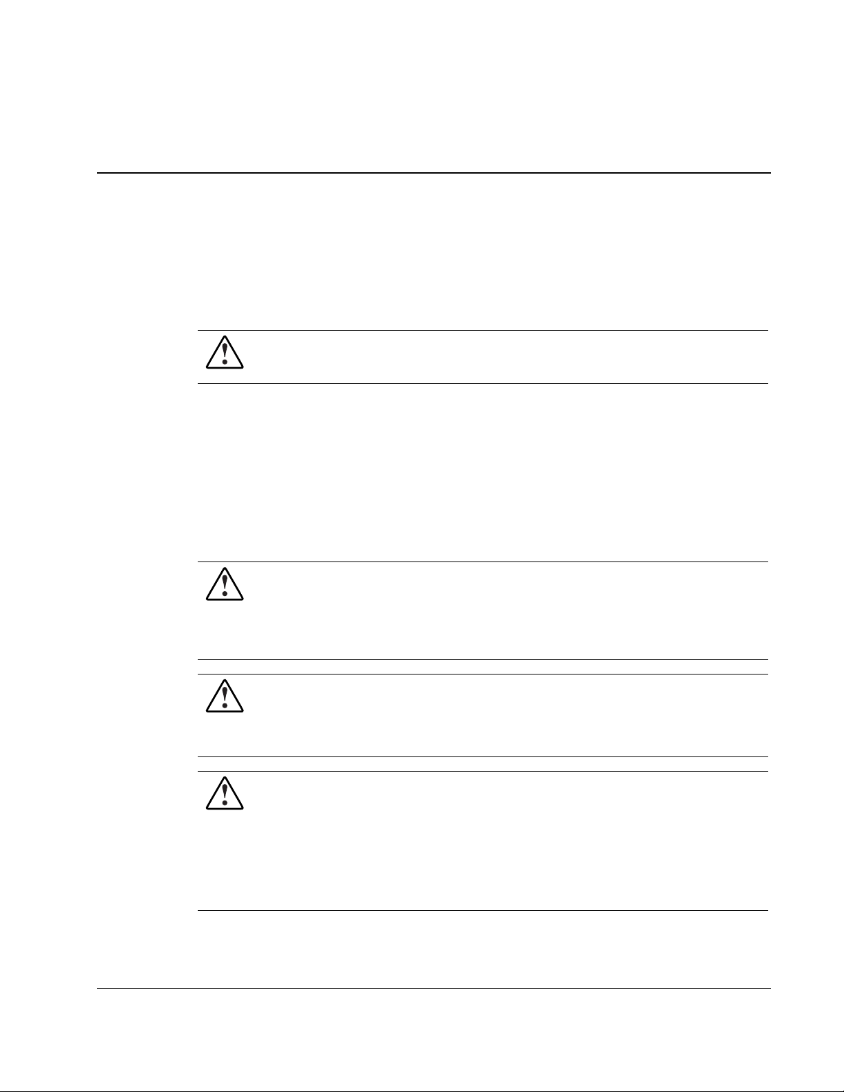
Figure 1-1: Exploded view of the ProLiant ML570 Generation 2 server
chassis components
1-2 HP ProLiant ML570 Generation 2 Server Maintenance and Service Guide
Page 11

Chassis Components Spare Parts List
Table 1-1: Chassis Components Spare Parts List
Item Description Spare Part Number
1 Locking casters 296227-001
2
Blanks kit
a) Removable media bay blank
b) Power supply blank
3
Tower cover kit
a) Access panel
Hood labels*
b) Tower cover
c) Front bezel door
4
Rack bezel kit
Rack bezel
Handles*
5 Hard drive blank 122759-001
Illustrated Parts Catalog
253071-001
309619-001
249150-001
*Not shown
HP ProLiant ML570 Generation 2 Server Maintenance and Service Guide 1-3
Page 12
Illustrated Parts Catalog
System Components Exploded View
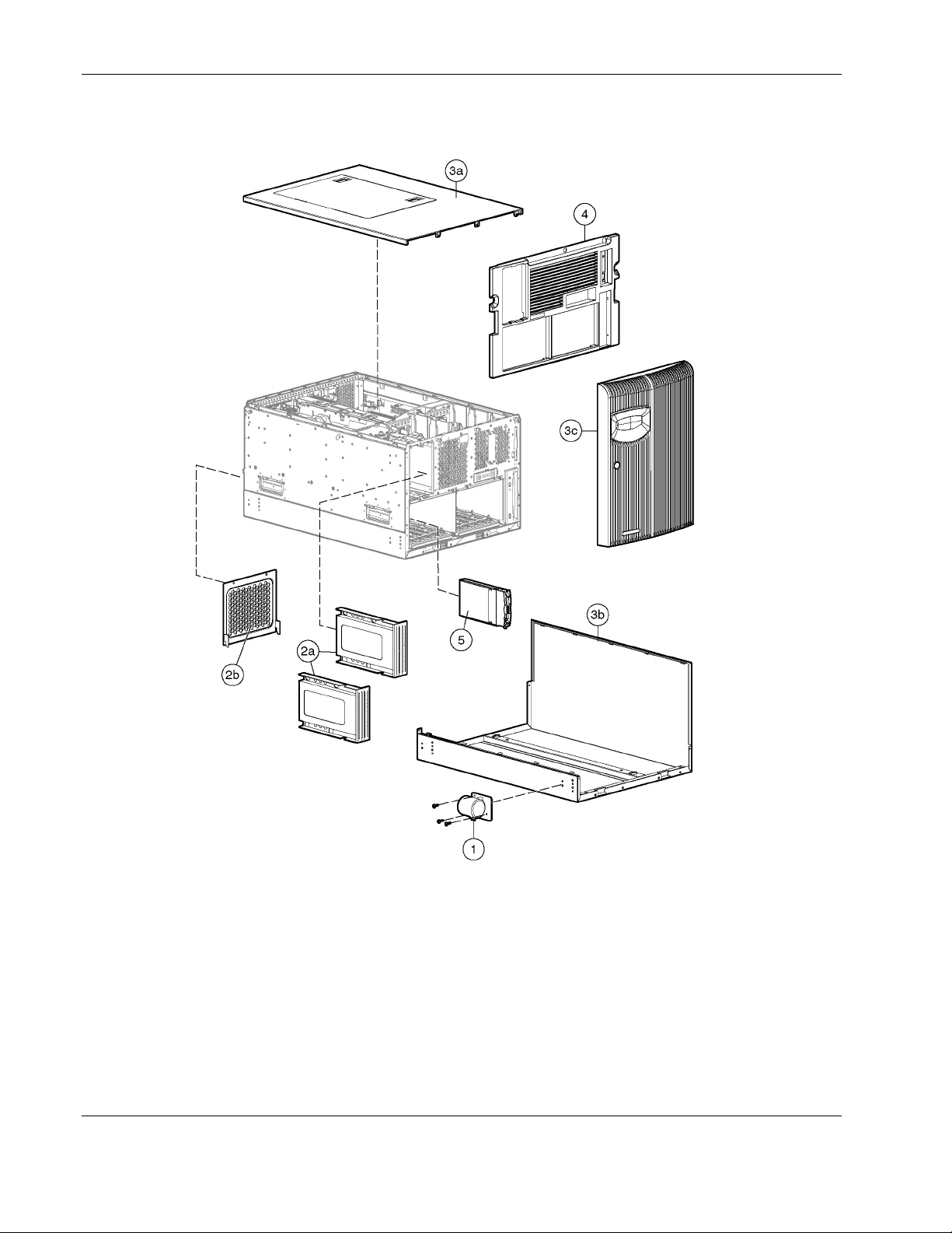
Figure 1-2: Exploded view of the ProLiant ML570 Generation 2 server system
components
1-4 HP ProLiant ML570 Generation 2 Server Maintenance and Service Guide
Page 13

System Components Spare Parts List
Table 1-2: System Components Spare Parts List
Item Description Spare Part Number
1 Power supply, hot-plug 600-W 231782-001
2 Redundant drive fans, hot-plug 92 mm (3.6 in) 161657-001
Drive fan power cable bracket* 249147-001
3 Drive fan air baffle 178195-001
4 Processor and I/O fans, hot-plug 127 mm (5 in) 122225-001
5 Fan basket 161658-001
Backplanes
6 SCSI backplane 263035-001
7 Power backplane 233962-001
Mass Storage Devices
8 IDE CD-ROM drive (48X) 288894-001
9 Diskette drive 233409-001
10
Fan bracket kit
a) Processor fan bracket
b) I/O fan bracket
Illustrated Parts Catalog
159321-001
*Not shown
HP ProLiant ML570 Generation 2 Server Maintenance and Service Guide 1-5
Page 14
Illustrated Parts Catalog
System Tray Components Exploded View
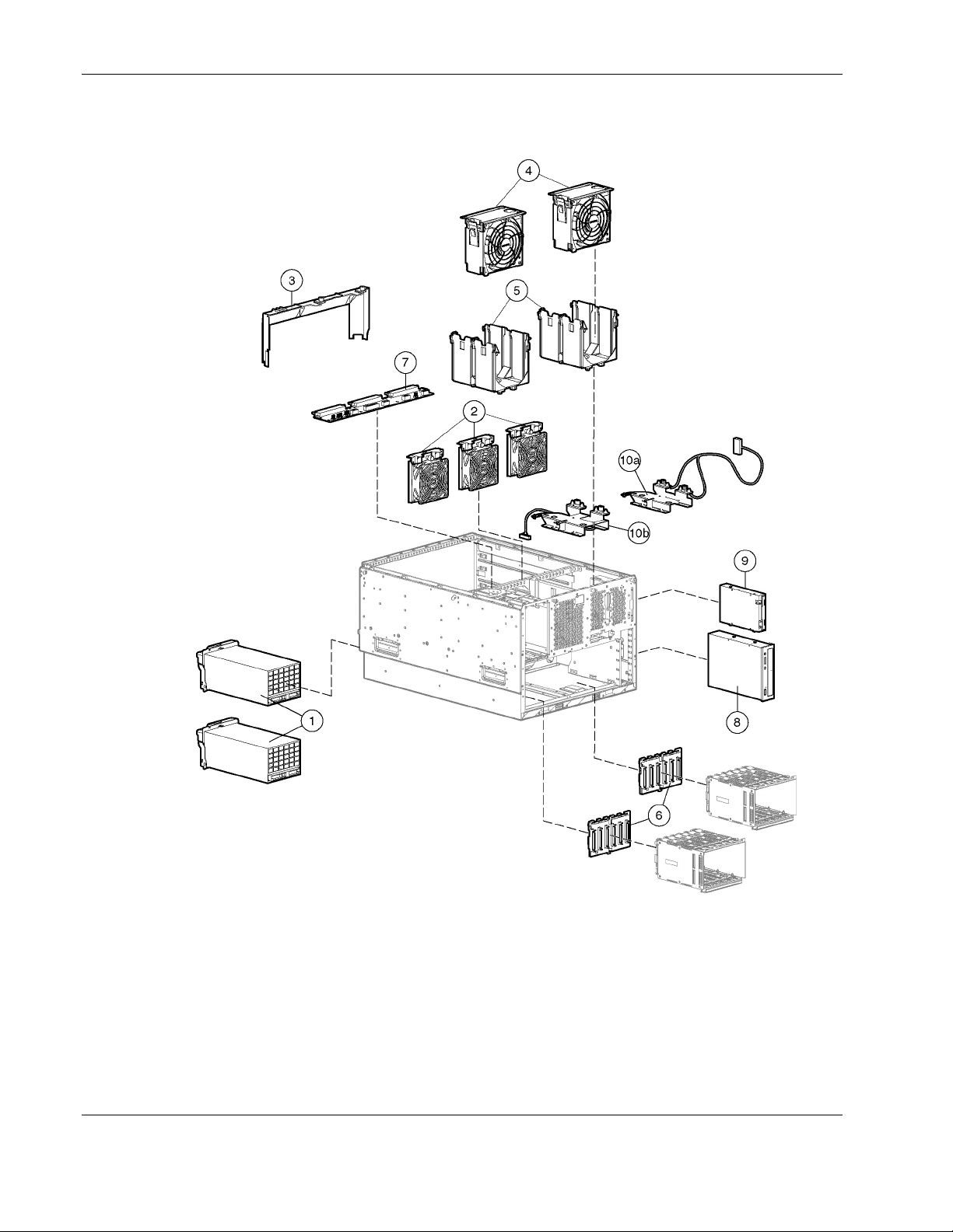
Figure 1-3: Exploded view of the ProLiant ML570 Generation 2 server
system tray components
1-6 HP ProLiant ML570 Generation 2 Server Maintenance and Service Guide
Page 15
System Tray Components Spare Parts List
Table 1-3: System Tray Components Spare Parts List
Item Description Spare Part Number
Boards
1 Memory board 285947-001
2 PCI-X backplane 233961-001
System components
3 Processor power module (PPM) 266655-001
4 Processor, 1.4-GHz Intel® XeonTM MP 272935-001
Processor, 1.5-GHz Xeon MP* 309617-001
Processor, 1.9-GHz Xeon MP* 311277-001
Processor, 2.0-GHz/1M Xeon MP* 327839-001
Processor, 2.0-GHz/2M Xeon MP* 309618-001
Processor, 2.2-GHz/2M Xeon MP* 352311-001
Processor, 2.5-GHz Xeon MP* 327840-001
Processor, 2.7-GHz/2M Xeon MP* 352312-001
Processor, 2.8-GHz Xeon MP* 327841-001
Processor, 3.0-GHz/4M Xeon MP* 352313-001
Memory (DIMMs)
5 256-MB PC1600, DDR, ECC, SDRAM DIMM 249674-001
512-MB PC1600, DDR, ECC, SDRAM DIMM* 249675-001
1-GB PC1600, DDR, ECC, SDRAM DIMM* 249676-001
2-GB PC1600, DDR, ECC, SDRAM DIMM* 265791-001
6
System board kit
a) System board
b) System tray
c) Processor retaining bracket
7 Rear processor air baffle with fan 278405-001
8
PCI-X Hot-plug basket and processor baffle
a) Front processor air baffle
b) Hot-plug expansion board basket
*Not shown
Illustrated Parts Catalog
233958-001
307383-001
continued
HP ProLiant ML570 Generation 2 Server Maintenance and Service Guide 1-7
Page 16

Illustrated Parts Catalog
Table 1-3: System Tray Components Spare Parts List continued
Item Description Spare Part Number
Expansion slot latch and base, blue
Expansion slot latch and base, carbon
PCI retaining clip, blue
PCI retaining clip, carbon
Memory board guide
Front bezel retainer
Plastics kit*
249746-001
Keyboard, carbon*
US English 311059-001
UK English 311059-031
German 311059-041
French 311059-051
Italian 311059-061
Spanish 311059-071
Danish 311059-081
Norwegian 311059-091
Swedish 311059-101
Canadian French 311059-121
Portuguese 311059-131
Turkish 311059-141
Greek 311059-151
Arab 311059-171
Belgium 311059-181
Hungarian 311059-211
Czech 311059-221
Slovakian 311059-231
Polish 311059-241
Russian 311059-251
Japanese 311059-291
Dutch 311059-331
Finnish 311059-351
International 311059-B31
BHCSY 311059-B41
*Not shown
continued
1-8 HP ProLiant ML570 Generation 2 Server Maintenance and Service Guide
Page 17

Illustrated Parts Catalog
Table 1-3: System Tray Components Spare Parts List continued
Item Description Spare Part Number
Miscellaneous*
3-V lithium replacement battery 153099-001
Enhanced keyboard, U.S. 244000-001
Mouse, carbon 311060-001
Torx T-15 tool 199630-001
Country kit, U.S. ML570 G2 308702-001
Return kit, rack (shipping box) 174795-001
Return kit, tower (shipping box) 265792-001
Drive fan cable 158465-001
CD-ROM/diskette drive cable 158469-001
SCSI drive cable 158470-001
LVD cable 158471-001
CD-ROM data cable 158473-002
34-Pin data cable 158472-002
Diskette drive data cables 158474-001
SCSI data cable, 2 drop 157855-001
SCSI data cable, blue 166298-024
SCSI data cable, yellow 166298-025
Internal to external SCSI data cable, 12 inch 232112-001
PCI to system board data cable 232111-001
Power backplane cable 232109-001
Front control panel with cable 225034-002
Backplane to system board cable 232110-001
*Not shown
Rack-mounting hardware kit 277921-001
Third-party rack-mounting hardware kit 277922-001
Power Cable Kit*
Signal Cable Kit*
ML570 Cable Kit*
159319-001
180305-001
249146-001
continued
HP ProLiant ML570 Generation 2 Server Maintenance and Service Guide 1-9
Page 18

Illustrated Parts Catalog
Table 1-3: System Tray Components Spare Parts List continued
Item Description Spare Part Number
18.2-GB hot-plug Wide-Ultra3 SCSI hard drive with tray
18.2-GB hot-plug Wide-Ultra3 hard drive (15,000 rpm, 1-inch) 189395-001
18.2-GB hot-plug Ultra320 hard drive (15,000 rpm, 1-inch) 289240-001
36.4-GB hot-plug Wide-Ultra3 hard drive (15,000 rpm, 1-inch) 233350-001
36.4-GB hot-plug Wide-Ultra3 hard drive (10,000 rpm, 1-inch) 177986-001
36.4-GB hot-plug Ultra320 hard drive (10,000 rpm, 1-inch) 289041-001
36.4-GB hot-plug Ultra320 hard drive (15,000 rpm, 1-inch) 289241-001
72.8-GB hot-plug Wide-Ultra3 hard drive (10,000 rpm, 1-inch) 233349-001
72.8-GB hot-plug Ultra320 hard drive (10,000 rpm, 1-inch) 289042-001
72.8-GB hot-plug Ultra320 hard drive (15,000 rpm, 1-inch) 289243-001
145.6-GB hot-plug Ultra320 hard drive (10,000 rpm, 1-inch) 289044-001
DVD drive 217801-001
Backplane, internal two-bay hot-plug SCSI drive bay 253761-001
Fan kit, internal two-bay hot-plug SCSI drive bay 253762-001
Options*
(10,000 rpm, 1-inch)
152190-001
*Not shown
1-10 HP ProLiant ML570 Generation 2 Server Maintenance and Service Guide
Page 19

Removal and Replacement Procedures
This chapter provides subassembly/module-level removal and replacement procedures for
HP ProLiant ML570 Generation 2 servers. After completing all necessary removal and
replacement procedures, run the Diagnostics program to be sure that all components operate
properly.
You need the following items for some procedures:
Torx T-15 tool
•
Torx T-10 tool
•
Diagnostics Utility from the SmartStart CD
•
Wrist strap
•
Safety Considerations
2
Before performing service procedures, review the following safety information.
Electrostatic Discharge
A discharge of static electricity can damage static-sensitive devices or microcircuitry. Proper
packaging and grounding techniques are necessary precautions to prevent damage. To
prevent electrostatic damage:
•
Transport products in static-safe containers such as conductive tubes, bags, or boxes.
•
Keep electrostatic-sensitive parts in their containers until they arrive at static-free
stations.
Cover workstations with approved static-dissipating material. Use a wrist strap connected
•
to the work surface and properly grounded (earthed) tools and equipment.
Keep work area free of nonconductive materials such as ordinary plastic assembly aids
•
and foam packing.
Be sure that you are properly grounded (earthed) when touching a static-sensitive
•
component or assembly.
Avoid touching pins, leads, or circuitry.
•
Use nonconductive field service tools.
•
HP ProLiant ML570 Generation 2 Server Maintenance and Service Guide 2-1
Page 20
Removal and Replacement Procedures
Symbols on Equipment
These symbols may be located on equipment in areas where hazardous conditions may exist.
Any product or assembly marked with these symbols indicates that the
component exceeds the recommended weight for one individual to handle safely.
66 kg
160 lb
WARNING: To reduce the risk of personal injury or damage to the equipment,
observe local occupational health and safety requirements and guidelines for
manual material handling.
Any surface or area of the equipment marked with these symbols indicates the
presence of a hot surface or a hot component.
WARNING: To reduce the risk of injury from a hot component, allow the surface
to cool before touching it.
Any surface or area of the equipment marked with these symbols indicates the
presence of electrical shock hazards. The enclosed area contains no
operator-serviceable parts.
WARNING: To reduce the risk of injury from electrical shock hazards, do not
open this enclosure.
Any RJ-45 receptacle marked with these symbols indicates a network interface
connection.
WARNING: To reduce the risk of electric shock, fire, or damage to the equipment,
do not plug telephone or telecommunications connectors into this receptacle.
Rack Warnings and Cautions
WARNING: To reduce the risk of personal injury or damage to the equipment,
adequately stabilize the rack before extending a component outside the rack. Extend
only one component at a time. A rack may become unstable if more than one
component is extended.
WARNING: To reduce the risk of personal injury or damage to the equipment:
• Extend the leveling jacks to the floor.
• Rest the full weight of the rack on the leveling jacks.
• Attach the stabilizers to the rack, if it is a single rack installation.
• Couple the racks together in multiple rack installations.
WARNING: When installing the server in a telco rack, adequately secure the rack frame
to the building structure at the top and bottom.
2-2 HP ProLiant ML570 Generation 2 Server Maintenance and Service Guide
Page 21
WARNING: To reduce the risk of personal injury or damage to the equipment, use two
or more people to safely unload the rack from the pallet. An empty 42U rack weighs
115 kg (253 lb), is over 2.1 m (7 ft) tall, and may become unstable when moved on its
casters. Handle the rack from both sides as it rolls down the ramp from the pallet. Do
not stand in front of the rack.
CAUTION: Always begin by mounting the heaviest item on the bottom of the rack. Continue
to populate the rack from the bottom to the top.
Server Warnings and Cautions
WARNING: Do not exceed the level of repair specified in the procedures in the product
documentation. All troubleshooting and repair procedures are detailed to allow only
subassembly or module-level repair. Because of the complexity of the individual
boards and subassemblies, do not attempt to make repairs at the component level or to
make modifications to any printed wiring board. Improper repairs can create a safety
hazard.
WARNING: To reduce the risk of personal injury from hot surfaces, allow the hot-plug
drives and the internal system components to cool before touching.
WARNING: To reduce the risk of electric shock or damage to the equipment:
• Do not disable the AC power cord grounding plug. The grounding plug is an
important safety feature.
• Plug the power cord into a grounded (earthed) electrical outlet that is easily
accessible at all times.
• Unplug the power cord from each power supply to disconnect power to the
equipment.
WARNING: Before lifting the server, remove all hot-plug power supplies and hard
drives to reduce weight.
WARNING: The installation of internal options and routine maintenance and service of
this product should be performed by individuals who are knowledgeable about the
procedures, precautions, and hazards associated with equipment containing
hazardous energy levels.
WARNING: Do not use conductive tools that could bridge live parts. Remove all
watches, rings, or loose jewelry when working in hot-plug areas of an energized server.
WARNING: Do not replace non-hot-pluggable components while power is applied to
the product. First, shut down the product and disconnect all AC power cords.
Removal and Replacement Procedures
HP ProLiant ML570 Generation 2 Server Maintenance and Service Guide 2-3
Page 22
Removal and Replacement Procedures
WARNING: Be sure that the AC power supply branch circuit that provides power to the
rack is not overloaded. Maintaining a low electrical current draw reduces the risk of
personal injury, fire, or damage to the equipment. The total rack load should not
exceed 80 percent of the branch circuit rating. Consult the electrical authority having
jurisdiction over your facility for wiring and installation requirements.
CAUTION: Protect the server from power fluctuations and temporary interruptions with a
regulating uninterruptible power supply (UPS). This device protects the hardware from
damage caused by power surges and voltage spikes and keeps the system in operation
during a power failure.
CAUTION: Do not operate the server for extended periods without the access panel.
Operating the server without the access panel results in improper airflow and improper cooling
that can lead to thermal damage.
CAUTION: Reinstall each hard drive into the specific slot from which it was removed. Mixing
the hard drives adversely affects the system drive configuration.
Accessing Server Components
In order to access components in the server, any or all the following procedures may be
required:
Extending the server from the rack
•
Opening the hot-plug door
•
Removing the front bezel door (tower model only)
•
Removing the rack bezel (rack model only)
•
Removing the access panel
•
Opening the system tray
•
All procedures can be performed without powering down the server or causing system
shutdown.
2-4 HP ProLiant ML570 Generation 2 Server Maintenance and Service Guide
Page 23
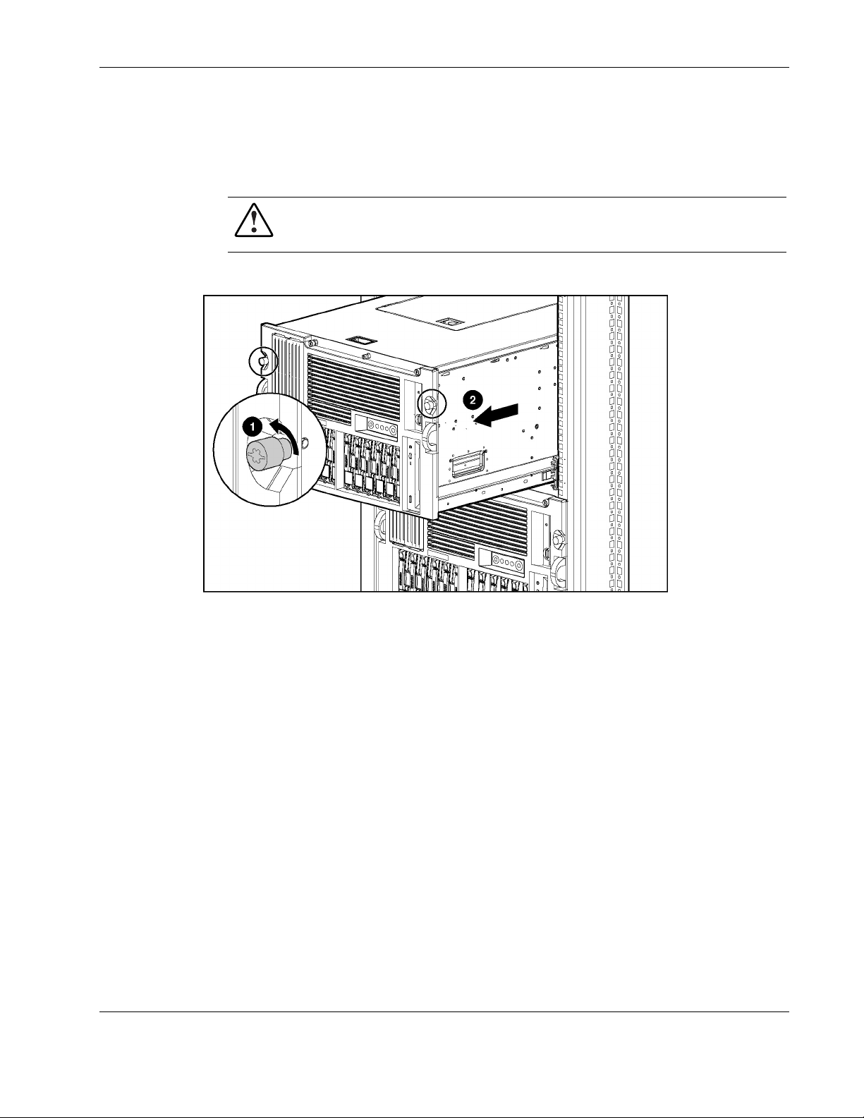
Extending the Server from the Rack
To extend the server from the rack:
1. Loosen the front panel thumbscrews that secure the server to the front of the rack (1).
WARNING: To reduce the risk of personal injury, be careful when pressing the
server rail release latches and sliding the component into or out of the rack. The
sliding rails could pinch your fingertips.
2. Extend the server until the server rail release latches engage (2).
Removal and Replacement Procedures
Figure 2-1: Extending the server from the rack
To slide the server back into the rack after performing the maintenance procedure:
1. Press the server rail release latches.
2. Slide the server fully into the rack.
3. Secure the server by tightening the thumbscrews.
HP ProLiant ML570 Generation 2 Server Maintenance and Service Guide 2-5
Page 24
Removal and Replacement Procedures
Opening the Hot-Plug Door
To open the hot-plug door:
1. Extend the server from the rack. Refer to “Extending the Server from the Rack” in this
chapter.
2. Locate the hot-plug door key. The key is located inside the front bezel door on the tower
model servers (1) or in a bag attached to the rear handle on the rack model servers (2).
Fig 2-2: Locating the hot-plug door and front bezel door keys
2-6 HP ProLiant ML570 Generation 2 Server Maintenance and Service Guide
Page 25
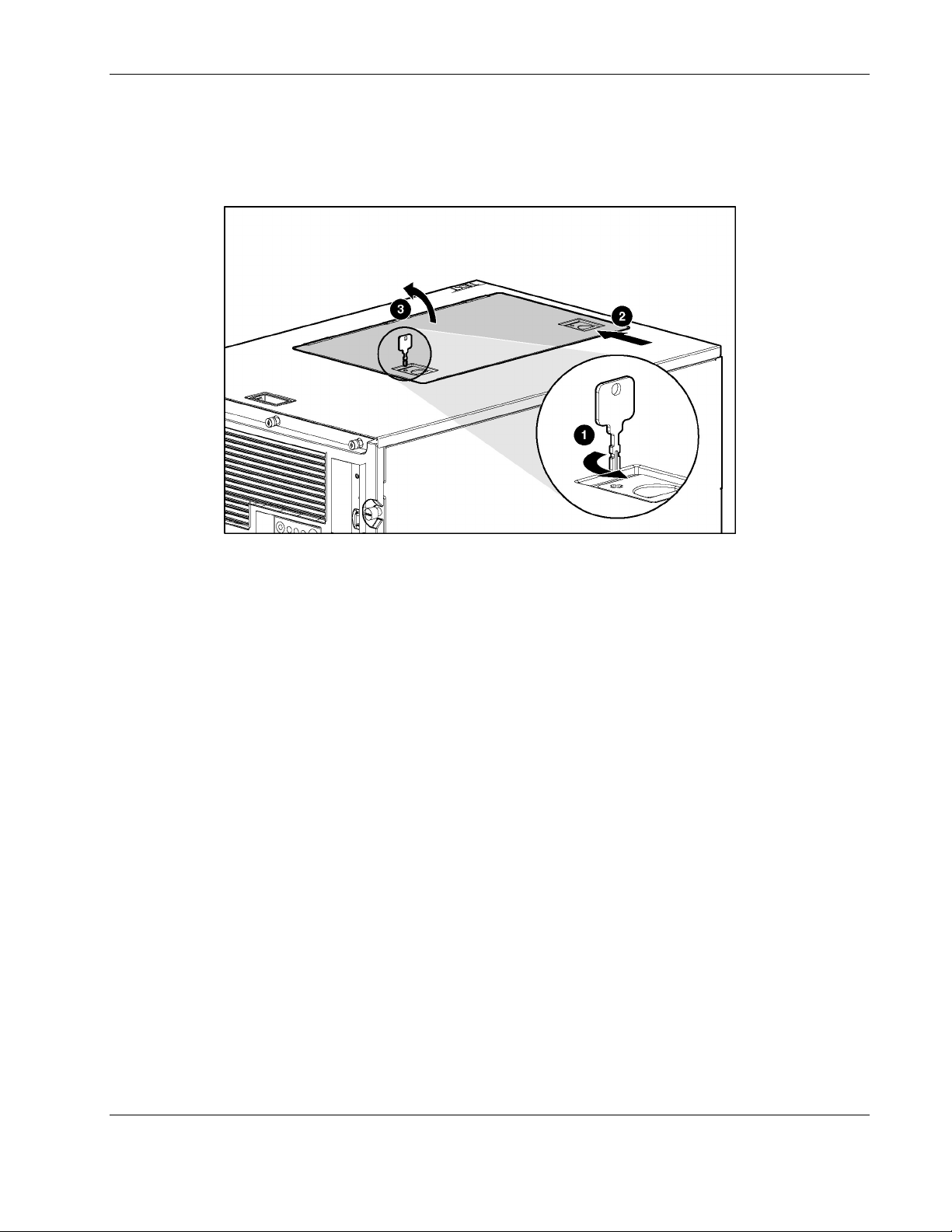
3. Unlock both locks on the hot-plug door (1).
4. Slide the hot-plug door latches open (2).
5. Open the hot-plug door (3).
Removal and Replacement Procedures
Figure 2-3: Opening the hot-plug door
Reverse steps 3 through 5 to close the hot-plug door.
HP ProLiant ML570 Generation 2 Server Maintenance and Service Guide 2-7
Page 26
Removal and Replacement Procedures
Removing the Front Bezel Door (Tower Model Only)
WARNING: To reduce the risk of personal injury from hot surfaces, allow the internal
system components to cool before handling the components.
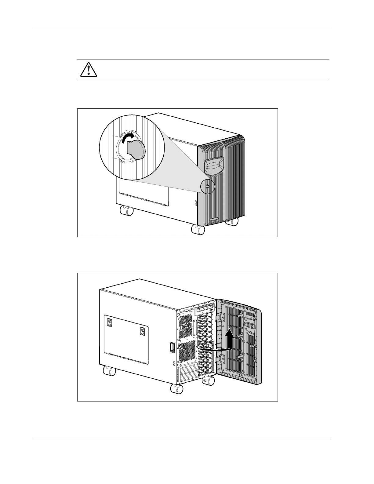
To remove the front bezel door:
1. Unlock the front bezel door.
Figure 2-4: Unlocking the front bezel door
2. Swing open the front bezel door fully.
3. Lift the front bezel door, and pull the door away from the chassis hinges.
Figure 2-5: Removing the front bezel door (tower model only)
Reverse steps 1 through 3 to replace the front bezel door.
2-8 HP ProLiant ML570 Generation 2 Server Maintenance and Service Guide
Page 27
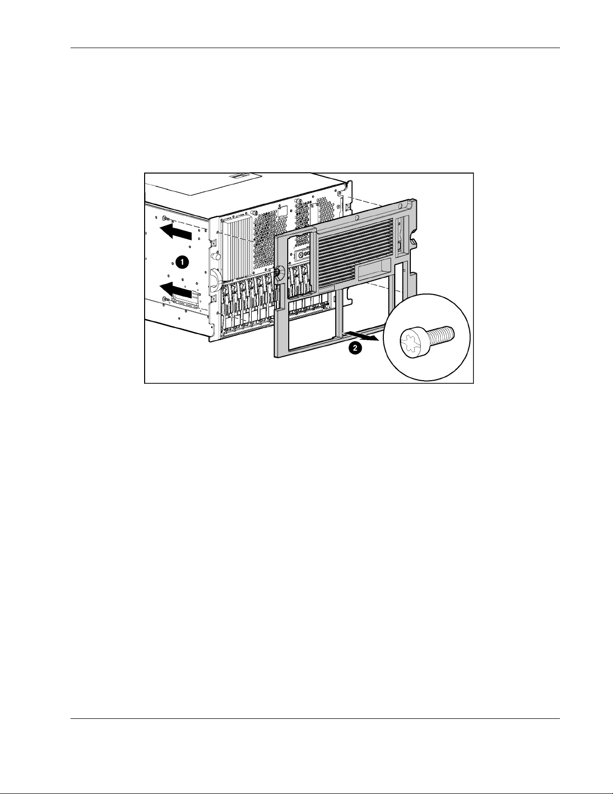
Removing the Rack Bezel (Rack Model Only)
To remove the rack bezel:
1. Remove the four Torx T-15 screws (two per side) securing the rack bezel to the
chassis (1).
2. Pull the rack bezel away from the chassis (2).
Removal and Replacement Procedures
Figure 2-6: Removing the rack bezel (rack model only)
Reverse steps 1 and 2 to replace the rack bezel.
Removing the Access Panel
To remove the access panel:
1. Open the front bezel door (tower model only) and lay the server on its side with the
access panel facing upward. Refer to “Removing the Front Bezel Door (Tower Model
Only)” in this chapter.
2. Extend the server from the rack (rack model only). Refer to “Extending the Server from
the Rack” in this chapter.
HP ProLiant ML570 Generation 2 Server Maintenance and Service Guide 2-9
Page 28
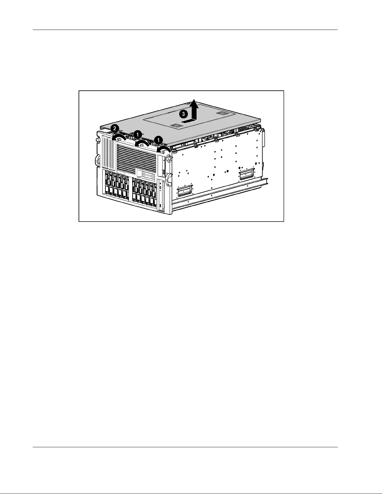
Removal and Replacement Procedures
3. Loosen the thumbscrews on the front of the chassis (1).
4. Use the Torx T-15 tool that ships with the server to loosen the retaining screw located on
the front of the chassis next to the two thumbscrews (2).
5. Slide the access panel toward the back of the server, and lift it away from the chassis (3).
Figure 2-7: Removing the access panel
Reverse steps 1 through 5 to replace the access panel.
Opening the System Tray
To open the system tray:
1. Remove the access panel. Refer to “Removing the Access Panel” in this chapter.
2-10 HP ProLiant ML570 Generation 2 Server Maintenance and Service Guide
Page 29
Removal and Replacement Procedures
2. Press the latch adjacent to the system tray release handle to release the system tray (1).
3. Grasp the system tray release handle and pull the tray from the chassis until it stops in the
extended position (2).
NOTE: If the server is mounted into a rack, the system tray latches can be reached more easily by
extending the server from the rack (approximately the depth of the drives) before sliding the system
tray from the back of the chassis.
Memory
Figure 2-8: Opening the system tray
This section provides the following information about the memory components and
procedures for hot-plug and non-hot-plug removal and replacement of memory in the server.
Parts of the memory board
•
Memory board LEDs and icons
•
DIMM installation requirements
•
Removing a memory board
•
Removing a DIMM
•
Installing a DIMM
•
Installing a memory board
•
Configuring the memory
•
HP ProLiant ML570 Generation 2 Server Maintenance and Service Guide 2-11
Page 30
Removal and Replacement Procedures
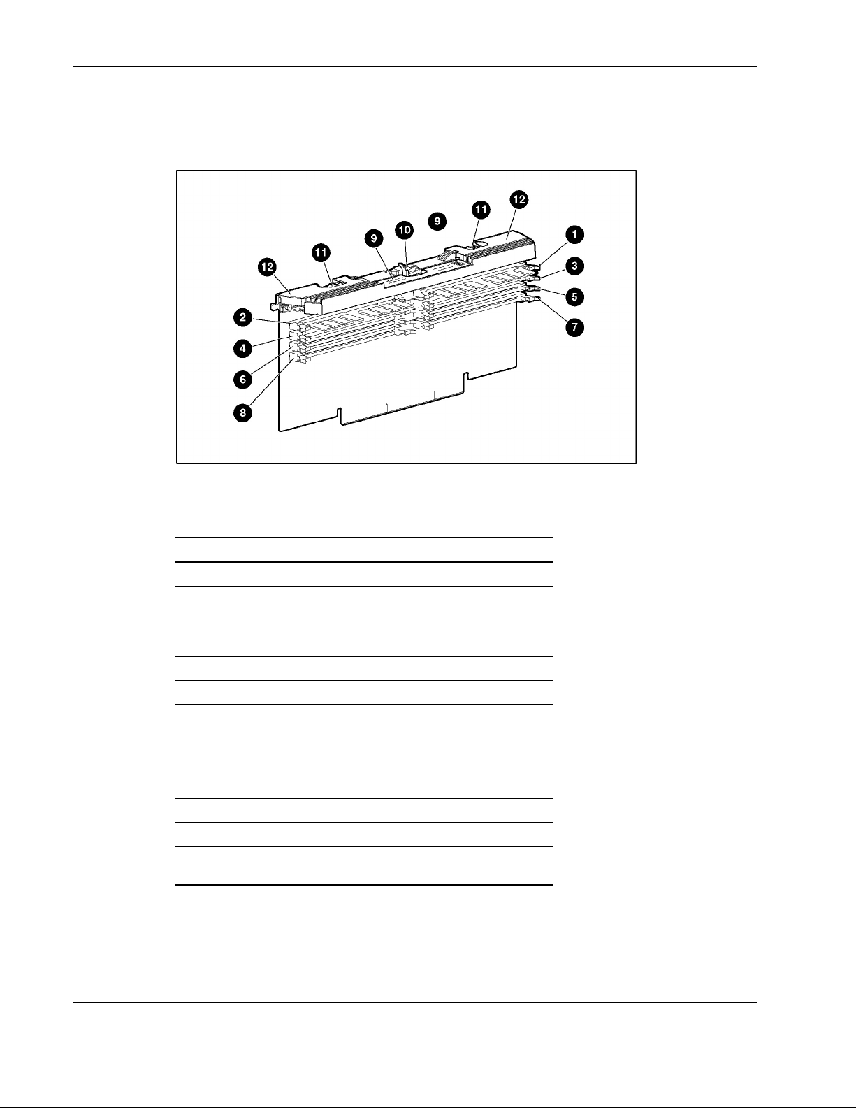
Parts of the Memory Board
Figure 2-9 and Table 2-1 identify the parts of the memory board.
Figure 2-9: Parts of the memory board
Table 2-1: Parts of the Memory Board
Item Description
1 DIMM slot 1, bank A (populated)
2 DIMM slot 2, bank A (populated)
3 DIMM slot 3, bank B
4 DIMM slot 4, bank B
5 DIMM slot 5, bank C
6 DIMM slot 6, bank C
7 DIMM slot 7, bank D*
8 DIMM slot 8, bank D*
9 LEDs
10 Locking switch
11 Release latches
12 Ejector levers
*When the server is configured for online spare memory, Bank
D on memory board 1 is the online spare bank.
2-12 HP ProLiant ML570 Generation 2 Server Maintenance and Service Guide
Page 31

Memory Board LEDs and Icons
Use Figure 2-10 and Tables 2-2 through 2-6 to identify LEDs and icons on the memory
board.
Removal and Replacement Procedures
Figure 2-10: Memory board LEDs and icons
Table 2-2: Advanced ECC (Standard) Memory LEDs
Item Description Indicator Status
1 Memory
Status
8 DIMM 1-8
status
1-4,
7, 8
All LEDs Flashing
Off Memory board is offline.
Green Memory board is online.
Flashing
green
Amber Memory error has occurred on this memory board.
Off DIMM is not installed.
Green DIMM is installed.
Amber Memory error has occurred on this DIMM.
Flashing
amber
amber
Memory board is busy.
Configuration error has occurred.
Memory board is in use; relock it immediately.
HP ProLiant ML570 Generation 2 Server Maintenance and Service Guide 2-13
Page 32

Removal and Replacement Procedures
Table 2-3: Online Spare Memory LEDs
Item Description Indicator Status
1 Memory
Status
2 Online Spare
Status
7 Online Spare
text
8 DIMM 1-8
Status
1-4,
7, 8
All LEDs Flashing
Off Memory board is offline.
Green Memory board is online.
Flashing
green
Amber Memory error has occurred on this memory board.
Off Memory board is not configured for online spare
Green Online spare memory is functioning properly.
Amber Memory error has occurred and system has failed over
Off Bank is not configured as an online spare bank.
Green Bank is configured as an online spare bank.
Flashing
green
Off DIMM is not installed.
Green DIMM is installed.
Amber Memory error has occurred on this DIMM.
Flashing
amber
amber
Memory board is busy.
memory.
to the online spare bank.
Failure has occurred and online spare bank is active.
Configuration error has occurred.
Memory board is in use; relock it immediately.
2-14 HP ProLiant ML570 Generation 2 Server Maintenance and Service Guide
Page 33

Removal and Replacement Procedures
Table 2-4: Single-Board Mirrored Memory LEDs
Item Description Indicator Status
1 Memory Status
3 Mirroring Status
8 DIMM 1-8 status
1-4,
7, 8
All LEDs Flashing amber Memory board is in use; relock it
Off Memory board is offline.
Green Memory board is online.
Flashing green Memory board is busy.
Amber Memory error has occurred on this
memory board.
Off Memory board is not configured for
mirrored memory.
Green Single-board mirrored memory is
functioning properly.
Amber Memory error has occurred and system
has failed over to the mirrored bank(s).
Off DIMM is not installed.
Green DIMM is installed.
Amber Memory error has occurred on this
DIMM.
Flashing amber Configuration error has occurred.
immediately.
HP ProLiant ML570 Generation 2 Server Maintenance and Service Guide 2-15
Page 34

Removal and Replacement Procedures
Table 2-5: Hot-Plug Mirrored Memory LEDs
Item Description Indicator Status
1 Memory Status
3 Mirroring Status
4 Ready to Hot Plug
8 DIMM 1-8 status
1-4,
7, 8
All LEDs Flashing amber Memory board is in use; relock it
Off Memory board is offline.
Green Memory board is online.
Flashing green Memory board is busy.
Amber Memory error has occurred on this
memory board.
Off Memory board is not configured for
mirrored memory.
Green Hot-plug mirrored memory is functioning
properly.
Amber Memory error has occurred and system
has failed over to the mirrored board.
Off Do not remove memory board—memory
board is not ready for removal.
Green Okay to remove memory board.
Off DIMM is not installed.
Green DIMM is installed.
Amber Memory error has occurred on this
DIMM.
Flashing amber Configuration error has occurred.
immediately.
Table 2-6: Memory Board Icons
Item Description Status
5 Lock Memory board is locked and cannot be removed.
6 Unlock Memory board is unlocked; do not remove unless the server
is off.
Note: The icon at which the memory board switch is pointed indicates whether the memory board is
locked or unlocked.
2-16 HP ProLiant ML570 Generation 2 Server Maintenance and Service Guide
Page 35

DIMM Installation Requirements
Observe the following DIMM configuration requirements when installing DIMMs:
Use only industry-standard PC1600 registered DDR SDRAM DIMMs in 256-MB,
•
512-MB, 1-GB, and 2-GB capacities.
Install DIMMs in pairs, one bank at a time.
•
Be sure that both DIMMs in a bank are the same capacity.
•
Be sure that bank A is populated.
•
IMPORTANT: HP recommends that you use only HP DIMMs. Third-party DIMMs may have additional
installation requirements. For information about third-party DIMM installation requirements, refer to the
HP Advanced Memory Protection white paper at www.hp.com.
IMPORTANT: You must power down the server before installing additional DIMMs.
IMPORTANT: Follow all DIMM configuration requirements carefully. If the DIMMs are not configured
properly, you receive an error message during POST.
Removal and Replacement Procedures
The server supports three types of optional Advanced Memory Protection:
•
Online spare memory
•
Single-board mirrored memory
•
Hot-plug mirrored memory
Each type includes Advanced ECC protection.
Additional Requirements for Online Spare Memory Technology
In addition to the DIMM configuration requirements for advanced ECC memory, observe the
following DIMM configuration requirements when installing DIMMs for online spare
memory:
•
Bank D is the online spare bank and must be populated when the server is configured for
online spare memory.
•
DIMMs installed in the online spare bank must be of equal or greater capacity than each
of those in the remaining banks.
HP ProLiant ML570 Generation 2 Server Maintenance and Service Guide 2-17
Page 36

Removal and Replacement Procedures
Additional Requirements for Single-Board Mirrored Memory Technology
In addition to the DIMM configuration requirements for advanced ECC memory, observe the
following DIMM configuration requirements when installing DIMMs for single-board
mirrored memory:
•
Bank C mirrors bank A, and bank D mirrors bank B. Banks A and C must always be
populated.
•
DIMMs in the mirrored banks must be configured identically to the banks they are
mirroring. Corresponding banks (for instance, bank A and bank C) must be populated
with DIMMs of the same capacity.
Additional Requirements for Hot-Plug Mirrored Memory Technology
In addition to the DIMM configuration requirements for advanced ECC memory, observe the
following DIMM configuration requirements when installing DIMMs for hot-plug mirrored
memory:
•
Two memory boards must be installed.
•
Both memory boards must be configured identically. Corresponding banks (for instance,
bank A on the memory board in slot 1 and bank A on the memory board in slot 2) must
be populated with DIMMs of the same capacity.
Removing a Memory Board
CAUTION: Electrostatic discharge can damage electronic components. Make sure you are
properly grounded before beginning any installation procedure.
To remove a memory board:
1. If the server is not configured for hot-plug mirrored memory, you must power down the
server. Refer to “Powering Down the Server” in this chapter.
If the server is configured for hot-plug mirrored memory, skip to step 2.
2. Open the hot-plug door. Refer to “Opening the Hot-Plug Door” in this chapter.
Hot-replacement procedure: Determine which memory board you want to remove by
locating the memory board with an amber memory status LED and one or more amber
DIMM status LEDs. The Ready to Hot Plug LED must be green, indicating that you can
perform a hot-plug procedure.
NOTE: If the Ready to Hot Plug LED is off on both boards, then you must power down the server
before replacing DIMMs.
2-18 HP ProLiant ML570 Generation 2 Server Maintenance and Service Guide
Page 37

Removal and Replacement Procedures
3. Disengage the locking switch (1).
Hot-replacement procedure: After turning the locking switch, the LEDs turn off, except
the amber LEDs. Wait until all green LEDs are off before proceeding. Make note of
which DIMM status LED remains amber. This is the DIMM you need to remove and
replace.
CAUTION: Do not attempt to unlock the memory board in an operational server when the
Ready to Hot Plug LED is not green. This generates an audible alarm and causes the
memory board LEDs to flash amber. Proceeding to remove the memory board after the
audible and visible alarms causes system failure.
CAUTION: To prevent system failure, do not remove the memory board from the server
until the memory status LED stops blinking.
4. Press the release latches inward firmly (2), disengaging the board from the server. Do not
squeeze the latches.
5. Lift the ejector levers up (3).
6. Pull the memory board up out of the server (4).
Hot-replacement procedure: While the memory board with the failed or degraded
DIMM is being replaced, the system continues to read and write from the operational
memory board.
Figure 2-11: Removing the memory board
HP ProLiant ML570 Generation 2 Server Maintenance and Service Guide 2-19
Page 38

Removal and Replacement Procedures
Removing a DIMM
To remove a DIMM:
1. Remove the memory board. Refer to “Removing a Memory Board” in this chapter.
2. Place the memory board on a level surface.
3. Open the DIMM slot latches (1) and remove the DIMM from the DIMM slot (2).
Figure 2-12: Removing a DIMM
2-20 HP ProLiant ML570 Generation 2 Server Maintenance and Service Guide
Page 39

Installing a DIMM
To install a DIMM:
1. Remove the memory board. Refer to “Removing a Memory Board” in this chapter.
2. Observe all DIMM installation requirements for the desired memory mode. Refer to the
“DIMM Installation Requirements” section in this chapter for each mode.
IMPORTANT: Follow all DIMM configuration requirements carefully. If the DIMMs are not
configured properly, you will receive an error message during POST and the DIMM LEDs will blink
amber.
3. Align the keyed portion of the bottom edge of the DIMM with the tab in the DIMM slot.
IMPORTANT: The bottom edge of the DIMM is designed so that it fits into the DIMM slot only one
way.
4. Press the DIMM firmly into the slot (1).
5. Push the latches into place (2).
Removal and Replacement Procedures
Figure 2-13: Installing and latching a DIMM
HP ProLiant ML570 Generation 2 Server Maintenance and Service Guide 2-21
Page 40

Removal and Replacement Procedures
Installing a Memory Board
To install a memory board:
1. Align the memory board with the memory slot and memory board guide clips.
2. Slide the memory board into the server (1), and close the ejector levers to seat the
memory board firmly (2).
Hot-replacement procedure: Any LEDs that were amber when the board was removed
from the server now illuminate amber again.
IMPORTANT: The LEDs reilluminate amber during this step to enable you to be sure which DIMM
failed. If you have already replaced the failed DIMM, disregard the amber LEDs. The LEDs change
back to green after the locking switch is engaged.
3. Engage the locking switch (3).
Hot-replacement procedure: All LEDs now turn off except the memory status LED,
which flashes green while data are copied from one memory board to the other. This
process may take up to a minute to complete. When the copying process is complete, the
other LEDs reilluminate as described in Table 2-7.
CAUTION: Do not remove the memory board while the memory status LED is flashing.
When the memory status LED is flashing, the memory board is transferring data.
Removing the memory board during data transfer may cause system failure.
Figure 2-14: Installing the memory board
4. If the server is not currently configured for hot-plug mirrored memory, power up the
server. Refer to the HP ProLiant ML570 Generation 2 Server Setup and Installation
Guide on the Documentation CD.
Hot-replacement procedure: If the server is configured for hot-plug mirrored memory,
skip to step 7.
5. Configure the memory. Refer to “Configuring the Memory” in this chapter.
2-22 HP ProLiant ML570 Generation 2 Server Maintenance and Service Guide
Page 41

Removal and Replacement Procedures
6. Reference the LEDs on the top of the memory board to make sure that the memory is
functioning properly. The following table describes what the LEDs look like for each
memory configuration when the DIMMs and memory board are functioning properly. For
more information on LEDs, refer to Chapter 4, “Connectors, LEDs, and Switches.”
Table 2-7: Memory LED States on a Properly Functioning Memory Board
Memory Configuration
LED
Memory Status Green Green Green Green
DIMMs 1-8, if
populated
Online Spare
Status
Mirroring Status Off Off Green Green
Online Spare
Text*
Ready to Hot
Plug
Advanced ECC
(Standard
Memory)
Green Green Green Green
Off Green Off Off
Off Green Off Off
Off Off Off Green
Online Spare
Memory
Single-Board
Mirrored
Memory
Hot-Plug
Mirrored
Memory
*If two memory boards are installed, the online spare text is only illuminated for the memory board in
slot 1.
NOTE: When the server is configured for online spare memory, Bank D is the online spare bank.
7. If any of the LEDs are illuminated solid amber, indicating a failed DIMM, or blinking
amber, indicating improper DIMM configuration, refer to the HP Servers
Troubleshooting Guide on the Documentation CD for instructions.
8. Close the hot-plug door.
9. Close the front bezel door (tower model only).
HP ProLiant ML570 Generation 2 Server Maintenance and Service Guide 2-23
Page 42

Removal and Replacement Procedures
Configuring the Memory
Configuring the server’s memory system requires configuring both hardware and software.
To configure the memory:
1. Remove the memory board. Refer to “Removing a Memory Board” in this chapter.
2. Install the required DIMMs based on the desired memory configuration. Be sure to
follow all DIMM installation requirements. Refer to the “DIMM Installation
Requirements” section in this chapter for each mode.
3. Install the memory board. Refer to “Installing a Memory Board” in this chapter.
4. Test the DIMMs:
a. Power on the server.
b. Press the F9 key to enter RBSU.
c. Select Advanced Options.
d. Change POST Speed Up to disable.
e. Press any key to return to the RBSU main menu.
f. Select System Options.
g. Select Advanced Memory Protection.
h. Select the desired memory mode.
i. Press the Esc key twice to go back to the main RBSU menu.
j. Press the F10 key to exit RBSU. The server reboots and tests all memory in the
system.
k. Once the memory has been tested, change POST Speed Up to enable for faster
system boot, if desired.
IMPORTANT: To reconfigure the memory mode after initial setup, you must reboot the system and
enter RBSU.
2-24 HP ProLiant ML570 Generation 2 Server Maintenance and Service Guide
Page 43

Hot-Plug Procedures
You can perform removal/replacement procedures for some server components without
powering down the server. The following removal/replacement procedures are hot-plug
capable:
Power supplies
•
Processor and I/O fans
•
Drive fans
•
Front and rear processor air baffles
•
SCSI hard drives
•
PCI and PCI-X Hot Plug expansion boards (in hot-plug slots)
•
Memory (refer to the “Memory” section in this chapter)
•
Hot-Plug Power Supplies
CAUTION: Do not hot-remove a power supply without a redundant power supply in place.
CAUTION: Hot-plug power supplies for the ProLiant ML570 Generation 2 server are keyed to
make sure that only 600-W hot-plug power supplies can be installed in the server. The
handles on 600-W power supplies are carbon (black) to distinguish them from other power
supplies, which are opal (white).
Removal and Replacement Procedures
To remove a hot-plug power supply:
1. Release the AC power cord from the tie wrap on the power supply.
2. Unplug the AC power cord from the power supply.
HP ProLiant ML570 Generation 2 Server Maintenance and Service Guide 2-25
Page 44
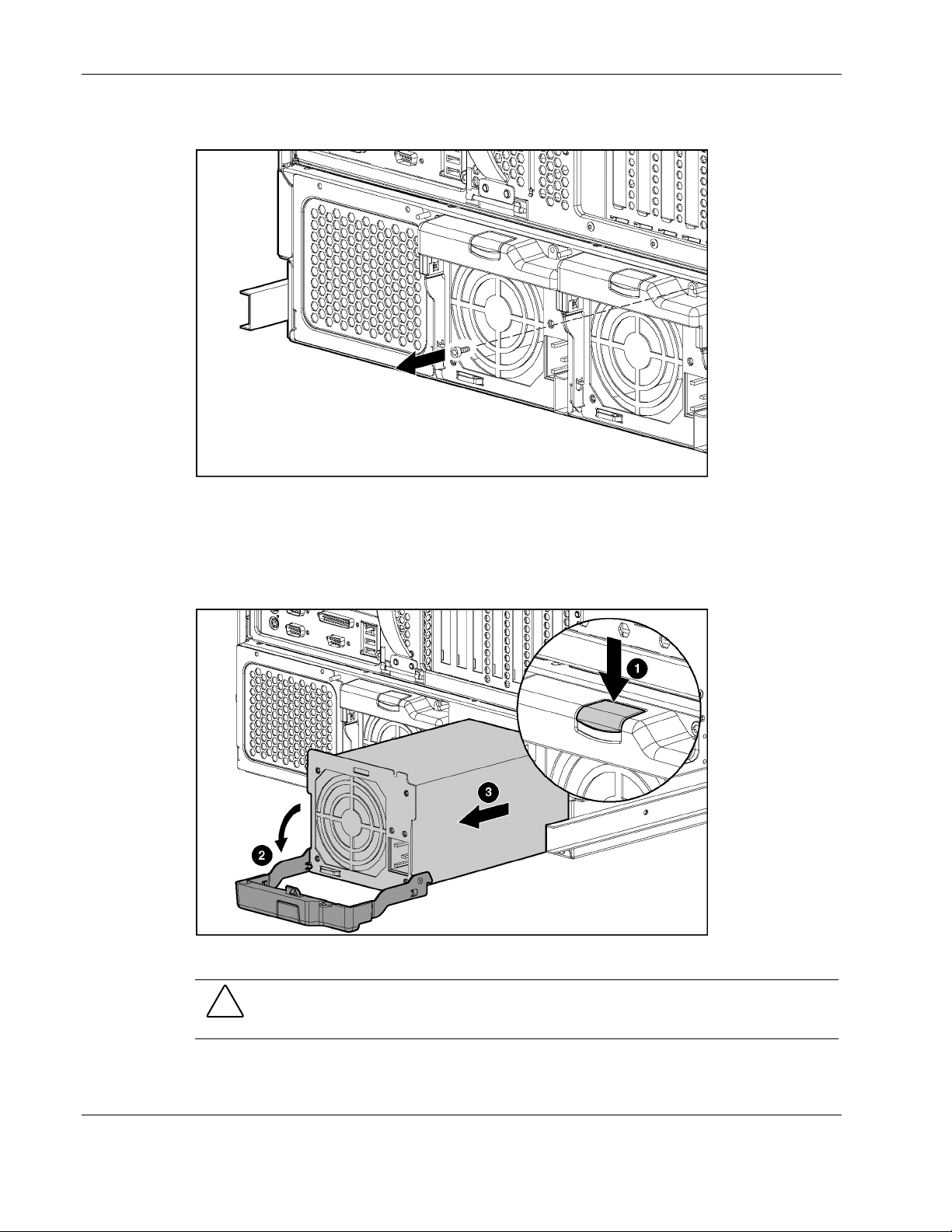
Removal and Replacement Procedures
3. Remove the retaining screw, if installed.
Figure 2-15: Removing the retaining screw
4. Press the latch in the middle of the power supply handle to release the handle (1).
5. Pull the handle downward until the unit releases from the server (2).
6. Slide the hot-plug power supply from the chassis (3).
Figure 2-16: Removing a hot-plug power supply
CAUTION: A power supply or power supply blank must always be installed in each power
supply bay for proper system cooling. If a power supply bay is left open, thermal damage may
occur.
Reverse steps 1 through 6 to replace a hot-plug power supply.
2-26 HP ProLiant ML570 Generation 2 Server Maintenance and Service Guide
Page 45

For information on power supply diagnosis, refer to “Hot-Plug Power Supply LEDs” in
Chapter 4, “Connectors, LEDs, and Switches.”
Hot-Plug Fans (Processor and I/O)
The server hot-plug fans are housed in two fan baskets. Each basket holds a primary and a
redundant hot-plug fan. The I/O fans cool the system board components, and the processor
fans cool the processors.
CAUTION: Never remove both hot-plug fans from either system fan basket while the server
is powered up. Overheating and damage to hardware could result. If the appropriate
HP software drivers are installed, the operating system software initiates a power shutdown in
case of overheating.
To remove a hot-plug processor or I/O fan:
1. Remove the front bezel door (tower model only) and lay the server on its side with the
access panel facing upward. Refer to “Removing the Front Bezel Door (Tower Model
Only)” in this chapter.
2. Extend the server from the rack (rack model only). Refer to “Extending the Server from
the Rack” in this chapter.
Removal and Replacement Procedures
3. Remove the access panel. Refer to “Removing the Access Panel” in this chapter.
4. Press and hold the locking latch (1).
5. Lift the hot-plug processor or I/O fan out of the fan basket (2).
Figure 2-17: Removing a hot-plug processor or I/O fan
Reverse steps 1 through 5 to replace a hot-plug processor fan or hot-plug I/O fan.
For information on hot-plug fan diagnosis, refer to “Hot-Plug Fan LEDs” in Chapter 4,
“Connectors, LEDs, and Switches.”
HP ProLiant ML570 Generation 2 Server Maintenance and Service Guide 2-27
Page 46

Removal and Replacement Procedures
Hot-Plug Fans (Drive)
The server ships standard with three hot-plug drive fans. Two fans are required for operation,
and the third fan is redundant.
To remove a hot-plug drive fan:
1. Remove the front bezel door (tower model only) and lay the server on its side with the
access panel facing upward. Refer to “Removing Front Bezel Door (Tower Model Only)”
in this chapter.
2. Extend the server from the rack (rack model only). Refer to “Extending the Server from
the Rack” in this chapter.
3. Remove the access panel. Refer to “Removing the Access Panel” in this chapter.
4. Open the system tray. Refer to “Opening the System Tray” in this chapter.
5. Loosen the thumbscrew located at the top of the fan (1).
6. Lift the hot-plug drive fan out of the chassis (2).
CAUTION: Hot-plug drive fans are located below all server cabling. Be careful not to
unplug or loosen cables when accessing hot-plug drive fans.
Figure 2-18: Removing a hot-plug drive fan
Reverse steps 1 through 6 to replace a hot-plug drive fan.
For information on hot-plug drive fan diagnosis, refer to “Hot-Plug Fan LEDs” in Chapter 4,
“Connectors, LEDs, and Switches.”
2-28 HP ProLiant ML570 Generation 2 Server Maintenance and Service Guide
Page 47
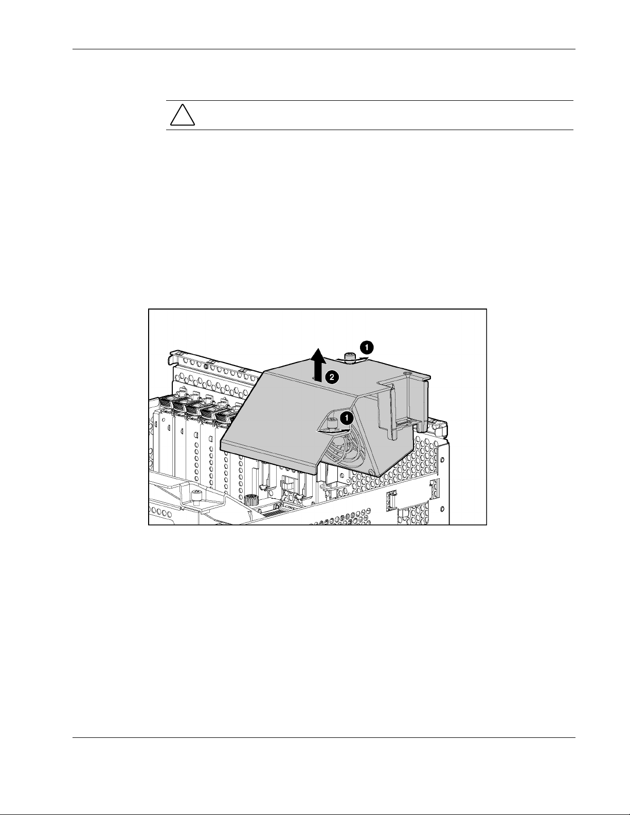
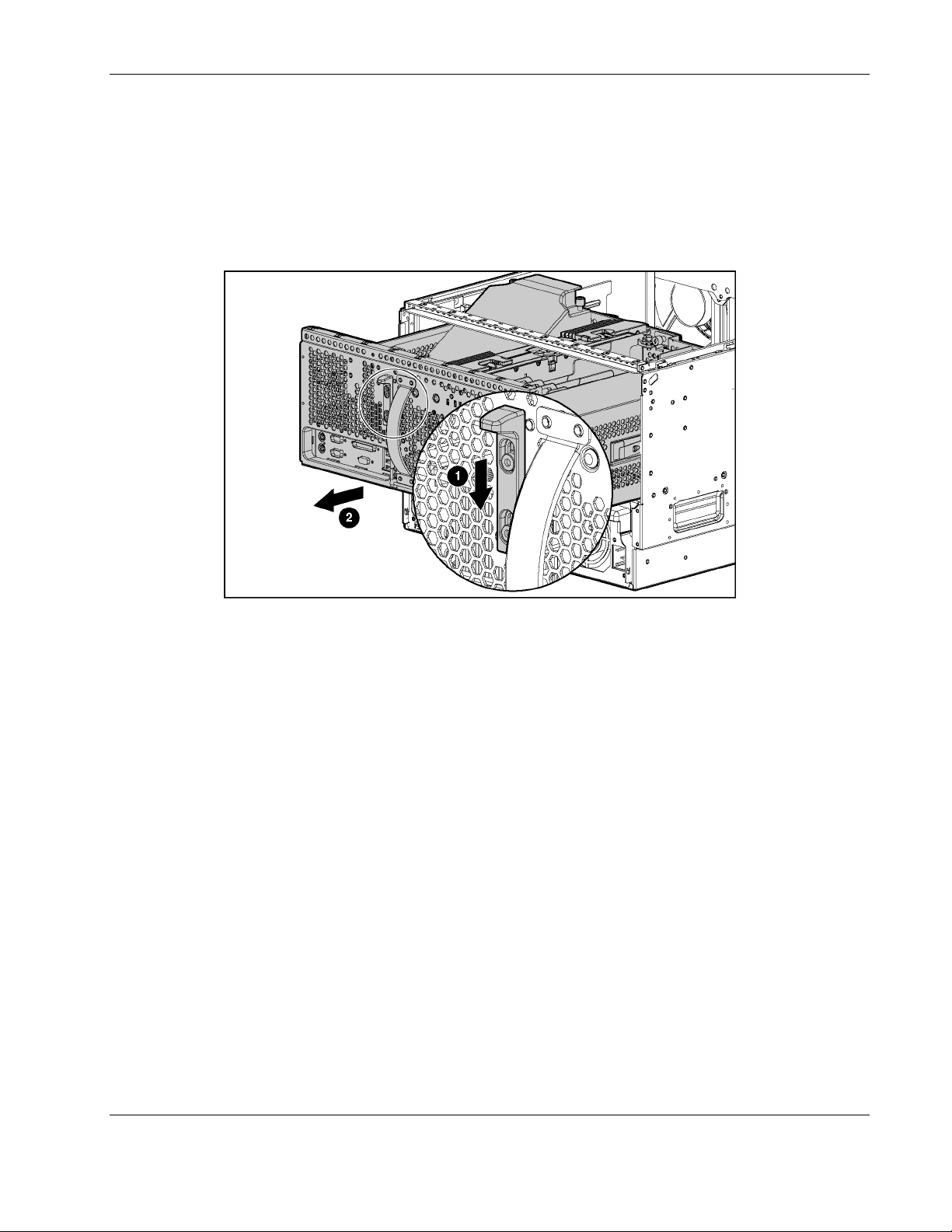
Processor Air Baffles
CAUTION: The removal and replacement of the rear and front processor air baffles must
be completed within 1 minute to prevent possible overheating and damage to hardware.
Rear Processor Air Baffle
To remove the rear processor air baffle:
1. Remove the front bezel door (tower model only), and lay the server on its side with the
access panel facing upward. Refer to “Removing the Front Bezel Door (Tower Model
Only)” in this chapter.
2. Remove the access panel. Refer to “Removing the Access Panel” in this chapter.
3. Remove the rear processor air baffle by loosening the two thumbscrews that secure it to
the system tray (1).
4. Lift the air baffle up and out of the server (2).
Removal and Replacement Procedures
Figure 2-19: Removing the rear processor air baffle
Reverse steps 1 through 4 to replace the rear processor air baffle.
Front Processor Air Baffle
To remove the front processor air baffle:
1. Remove the front bezel door (tower model only), and lay the server on its side with the
access panel facing upward. Refer to “Removing the Front Bezel Door (Tower Model
Only)” in this chapter.
2. Remove the access panel. Refer to “Removing the Access Panel” in this chapter.
3. Remove the rear processor air baffle. Refer to “Processor Air Baffles” in this chapter.
HP ProLiant ML570 Generation 2 Server Maintenance and Service Guide 2-29
Page 48

Removal and Replacement Procedures
4. Loosen the two thumbscrews on the front processor air baffle (1).
5. Lift the processor air baffle from the chassis (2).
Figure 2-20: Removing the front processor air baffle
Reverse steps 1 through 5 to replace the front processor air baffle.
SCSI Hard Drives
Be aware of the following guidelines cautioning unsafe hot-plug hard drive replacement.
•
Do not remove a degraded drive if any other member of the array is offline (the online
LED is off). No other drive in the array can be hot-plugged without data loss. The
exception to this is the use of RAID 1+0 as a fault-tolerant configuration. In this case,
drives are mirrored in pairs. More than one drive can fail and be replaced as long as the
drive or drives they are mirroring are online.
•
Do not remove a degraded drive if any member of an array is missing (previously
removed and not yet replaced).
Do not remove a degraded drive if any member of an array is being rebuilt, unless the
•
drive being rebuilt has been configured as an online spare. The online LED for the drive
flashes green or amber, indicating that a replaced drive is being rebuilt from the data
stored on the other drives.
NOTE: An online spare drive does not activate and start rebuilding after a predictive failure alert
because the degraded drive is still online. The online spare activates only after a drive in the array
has failed.
2-30 HP ProLiant ML570 Generation 2 Server Maintenance and Service Guide
Page 49

Removal and Replacement Procedures
• Do not replace multiple degraded drives at the same time, since the fault tolerance can be
compromised. When a drive is replaced, the controller uses data from the other drives in
the array to reconstruct data on the replacement drive. If more than one drive is removed,
a complete data set is not available to reconstruct data on the replacement drive or drives,
and permanent data loss can occur.
CAUTION: Do not turn off any external unit when the server containing the Smart Array
Controller is powered up. Also, do not power up the server before powering up the drive
enclosure. If these ordering rules are not followed, the Smart Array Controller may mark
the drives in this enclosure as “failed,” resulting in permanent data loss.
To remove a hard drive:
1. Open the front bezel door (tower model only). Refer to “Removing the Front Bezel Door
(Tower Model Only)” in this chapter.
CAUTION: Remove or replace a hard drive only when the drive failure LED is amber.
Data loss can occur if a drive is removed when the drive online LED is green. Refer to
“Hot-Plug Drive LEDs” in Chapter 4 for more information.
CAUTION: Remove or replace only one hard drive at a time. The controller relies on
other drives to reconstruct data on the replaced drive. Drive reconstruction is active when
the drive online LED is flashing green.
2. Push the sliding release button (1).
3. Swing out the ejector lever (2).
4. Pull the drive out from the drive cage (3).
CAUTION: Always populate drive bays with either a hard drive or blank. Proper airflow
can only be maintained when the bays are populated. Unpopulated drive bays can lead to
improper cooling and thermal damage.
Figure 2-21: Removing a hard drive
HP ProLiant ML570 Generation 2 Server Maintenance and Service Guide 2-31
Page 50

Removal and Replacement Procedures
Reverse steps 1 through 4 to replace a hard drive.
PCI and PCI-X Hot Plug Expansion Boards
CAUTION: Do not attempt a PCI Hot Plug procedure if the operating system does not
provide PCI Hot Plug support or if you do not have the appropriate device drivers installed.
Failure to take these precautions causes system shutdown and risks data integrity.
CAUTION: To avoid critical errors, do not open the expansion slot latch if the green power
LED is on or blinking. Use the PCI Hot Plug button or the software application to turn off
power to the slot.
Use either the PCI-X Hot Plug button on the server or the operating system’s PCI-X Hot Plug
Utility to control the PCI-X Hot Plug slots.
• • The PCI-X Hot Plug button and the PCI-X Hot Plug Utility enable you to power up or
power down a PCI-X Hot Plug expansion slot. The PCI-X Hot Plug button enables direct
access at each hot-plug expansion slot.
PCI Hot Plug software support for each operating system is available online. For more
information, refer to the PCI Hot Plug Administrator’s Guide on the Documentation CD.
The server includes seven PCI-X expansion slots. Use the Figure 2-22 and Table 2-8 to
identify each slot.
Figure 2-22: PCI-X expansion slots
2-32 HP ProLiant ML570 Generation 2 Server Maintenance and Service Guide
Page 51

Table 2-8: PCI-X Expansion Slots and Buses
Item Slot Bus
Removal and Replacement Procedures
1 Slot 1 (hot-plug)
2 Slot 2 (hot-plug)
3 Slot 3 (hot-plug)
4 Slot 4 (hot-plug)
5 Slot 5
6 Slot 6
7 Slot 7* PCI-X bus
*Slot 7 is recommended for the Remote Insight Lights-Out Edition II.
Shared bus
Shared bus
Shared bus
PCI-X Hot Plug expansion slots are accessible through the hot-plug door.
To remove an expansion board from a PCI-X Hot Plug slot:
1. Extend the server from the rack (rack model only). Refer to “Extending the Server from
the Rack” in this chapter.
2. Open the hot-plug door. Refer to “Opening the Hot-Plug Door” in this chapter.
HP ProLiant ML570 Generation 2 Server Maintenance and Service Guide 2-33
Page 52

Removal and Replacement Procedures
3. Press the port-colored PCI-X Hot Plug button to power down the slot (1). The power
LED flashes until shutdown is complete. Refer to “PCI-X Hot Plug LEDs” in Chapter 4,
“Connectors, LEDs, and Switches,” to determine the current PCI-X Hot Plug slot status.
CAUTION: To prevent data loss, do not open an expansion slot latch when the power
LED for the slot is on.
4. When the power LED for the slot is off, remove cables to the selected expansion board.
5. Push the tab on the expansion slot latch (2).
6. Swing the latch back to unlock the expansion board (3).
Figure 2-23: Pushing the PCI-X Hot Plug button and releasing the
expansion slot latch
2-34 HP ProLiant ML570 Generation 2 Server Maintenance and Service Guide
Page 53

Removal and Replacement Procedures
7. Release the PCI-X retaining clip (1).
8. Lift the expansion board release handle to lift the board from the slot (2).
9. Remove the board from the slot (3).
Figure 2-24: Removing a PCI-X Hot Plug expansion board
Before replacing the expansion board, review the following information:
• • Balancing is the paired arrangement of expansion boards for optimal performance based
on the bus architecture of the expansion slots. Properly balancing the expansion boards
across buses can improve performance.
To balance expansion boards, populate slots across different buses before populating two
slots on the same bus.
HP ProLiant ML570 Generation 2 Server Maintenance and Service Guide 2-35
Page 54

Removal and Replacement Procedures
Table 2-9 provides a guideline for slot population order.
NOTE: The slot population order that follows is a recommendation only; any PCI or PCI-X expansion
board may reside in any slot.
Table 2-9: Recommended PCI-X Expansion Slot Population Order
Slot Number Population Order
1 1
2 5
3 2
4 6
5 3
6 7
7* 4 PCI-X bus
*Slot 7 is recommended for the Remote Insight Lights-Out Edition II due to
internal cabling requirements.
Shared PCI-X bus
Shared PCI-X bus
Shared PCI-X bus
The operating system detects the PCI devices in the slots in this order:
1-2-3-4-5-6-7
For more information about PCI bus architecture and numbering, refer to the white paper,
PCI Bus Numbering in a Windows NT Environment, at
www.hp.com/servers/proliant/manage
Reverse steps 1 through 9 to replace the expansion board.
Preparing the Server for Non-Hot-Plug Procedures
Before replacing non-hot-plug devices, the following procedures must be performed:
Power down the server
•
Extend the server from the rack
•
Remove the server from the rack
•
2-36 HP ProLiant ML570 Generation 2 Server Maintenance and Service Guide
Page 55
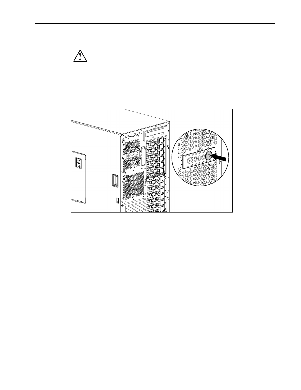
Powering Down the Server
WARNING: It is necessary to be knowledgeable of electrostatic discharge information
before preparing the server. For electrostatic discharge information, refer to
“Electrostatic Discharge Information” in this chapter.
To power down the server:
1. Remove the front bezel door (tower model only). Refer to “Removing the Front Bezel
Door (Tower Model Only)” in this chapter.
2. Press the Power On/Standby button.
Removal and Replacement Procedures
Figure 2-25: Pressing the Power On/Standby button
3. Be sure that the front panel power LED indicator is amber and that the fans are off.
4. Disconnect all AC power cords from the server.
5. Disconnect all external peripheral devices from the server.
HP ProLiant ML570 Generation 2 Server Maintenance and Service Guide 2-37
Page 56

Removal and Replacement Procedures
Extending the Server from the Rack
To extend the server from the rack:
1. Loosen the front panel thumbscrews that secure the server to the front of the rack (1).
2. Extend the server until the server rail release latches engage (2).
Figure 2-26: Extending the server from the rack
Removing the Server from the Rack
WARNING: To reduce the risk of personal injury or damage to the equipment, obser
local occupational health and safety requirements and guidelines for manual material
handling.
WARNING: Before lifting the server, remove all hotweight.
WARNING:
personal injury or damage to the equipment:
• Remove all hot-plug power supplies to reduce the weight of the server before
lifting it.
• Observe local occupational health and safety requirements and guidelines for
manual material handling.
• Use more than one person to lift and stabilize the server.
The server is very heavy, up to 66 kg (146 lb). To reduce the risk of
ve
plug power supplies to reduce
2-38 HP ProLiant ML570 Generation 2 Server Maintenance and Service Guide
Page 57

Removal and Replacement Procedures
To remove the server from the rack:
1. Power down the server. Refer to “Powering Down the Server” in this chapter.
2. Loosen the thumbscrews that hold the cable management arm bracket to the back of the
server (1).
3. Slide the cable management arm bracket up and remove it from the server (2).
Figure 2-27: Removing the cable management arm
4. Loosen the front panel thumbscrews and pull the server out of the front of the rack until it
stops in the extended position.
5. Press the release latches.
Figure 2-28: Pressing the release latches
HP ProLiant ML570 Generation 2 Server Maintenance and Service Guide 2-39
Page 58

Removal and Replacement Procedures
6. Pull the server out of the front of the rack.
Figure 2-29: Removing the server from the rack
7. Place the server on a nonconductive, level surface.
Non-Hot-Plug Procedures
In order to remove or replace any non-hot-plug component, you must first power down the
server. The following non-hot-plug procedures are described in this section.
System Battery
•
Processor Power Modules (PPMs)
•
Processors
•
Expansion Boards
•
Hot-Plug Expansion Board Basket
•
PCI Backplane
•
System Tray
•
Power Backplane
•
Fan Basket
•
Processor Fan Bracket with Cable
•
Drive Air Baffle
•
CD-ROM Drive
•
Diskette Drive
•
Removable Media Devices
•
2-40 HP ProLiant ML570 Generation 2 Server Maintenance and Service Guide
Page 59

• Internal Two-Bay Hot-Plug SCSI Drive Cage Fans (Optional)
Drive Cage Backplane
•
Drive Fan Cable and Cable Bracket
•
Front Panel LED Assembly
•
System Battery
Removal and Replacement Procedures
CAUTION: Loss of BIOS settings occurs when the system battery is removed. BIOS settings
must be reconfigured whenever the battery is replaced. Power up the server and run RBSU.
WARNING: This server contains an internal lithium manganese dioxide or vanadium
pentoxide battery. A risk of fire and burns exists if the battery pack is not handled
properly. To reduce the risk of personal injury:
• Do not attempt to recharge the battery.
• Do not expose to temperatures higher than 60°C (140°F).
• Do not disassemble, crush, puncture, short external contacts, or dispose of in fire
or water.
• Replace only with the HP spare designated for this server.
CAUTION: Do not dispose of batteries, battery packs, and accumulators with the
general household waste. To forward them to recycling or proper disposal, use the
public collection system or return them to either HP or the nearest HP authorized
service provider.
To remove the battery:
1. Prepare the server for a non-hot-plug procedure. Refer to “Preparing the Server for
Non-Hot-Plug Procedures” in this chapter.
2. Remove the front bezel door (tower model only), and lay the server on its side with the
access panel facing upward. Refer to “Removing the Front Bezel Door (Tower Model
Only)” in this chapter.
3. Remove the access panel. Refer to “Removing the Access Panel” in this chapter.
HP ProLiant ML570 Generation 2 Server Maintenance and Service Guide 2-41
Page 60

Removal and Replacement Procedures
4. Locate the battery on the system board.
Figure 2-30: Battery location on system board
5. Press the battery release lever away from the battery (1).
6. Lift the battery on the lever side and pull it out of the holder (2).
Figure 2-31: Removing the battery from the system board
Reverse steps 1 through 6 to replace the battery.
2-42 HP ProLiant ML570 Generation 2 Server Maintenance and Service Guide
Page 61

Processor Power Modules (PPMs)
1. Prepare the server for a non-hot-plug procedure. Refer to “Preparing the Server for
Non-Hot-Plug Procedures” in this chapter.
2. Remove the front bezel door (tower model only), and lay the server on its side with the
access panel facing upward. Refer to “Removing the Front Bezel Door (Tower Model
Only)” in this chapter.
3. Remove the access panel. Refer to “Removing the Access Panel” in this chapter.
4. Remove the rear and front processor air baffles. Refer to “Processor Air Baffles” in this
chapter.
5. Loosen the thumbscrew on the processor retaining bracket (1).
6. Lift the processor retaining bracket upward (2).
Removal and Replacement Procedures
Figure 2-32: Lifting the processor retaining bracket
HP ProLiant ML570 Generation 2 Server Maintenance and Service Guide 2-43
Page 62

Removal and Replacement Procedures
7. Lift the PPM straight up from its slot.
Figure 2-33: Removing a PPM
Processors
Reverse steps 1 through 7 to replace a PPM.
IMPORTANT: When installing a PPM, be sure the key slot in the PPM is aligned with the key in the
slot.
To remove a processor:
1. Prepare the server for a non-hot-plug procedure. Refer to “Preparing the Server for
Non-Hot-Plug Procedures” in this chapter.
2. Remove the front bezel door (tower model only), and lay the server on its side with the
access panel facing upward. Refer to “Removing the Front Bezel Door (Tower Model
Only)” in this chapter.
3. Remove the access panel. Refer to “Removing the Access Panel” in this chapter.
4. Remove the rear and front processor air baffles. Refer to “Processor Air Baffles” in this
chapter.
2-44 HP ProLiant ML570 Generation 2 Server Maintenance and Service Guide
Page 63

Removal and Replacement Procedures
5. Loosen the thumbscrew on the processor retaining bracket (1).
6. Lift the retaining bracket upward (2).
7. Remove the PPM. Refer to “Processor Power Modules (PPMs)” in this chapter.
8. Move the processor locking lever to the unlocked position (3).
Figure 2-34: Lifting the processor retaining bracket and the
processor locking lever
9. Lift the processor/heatsink assembly straight up from its socket.
Figure 2-35: Removing the processor/heatsink assembly
Reverse steps 1 through 9 to replace a processor.
HP ProLiant ML570 Generation 2 Server Maintenance and Service Guide 2-45
Page 64

Removal and Replacement Procedures
CAUTION: Do not force the processor into the processor socket. The processor pins are
fragile, and the processor socket is keyed to ensure proper installation.
NOTE: When inserting a processor into a socket, determine the correct processor orientation by
observing the keyed configuration of both the processor socket and the processor pins.
Expansion Boards
To remove a non-hot-plug expansion board:
1. Prepare the server for a non-hot-plug procedure. Refer to “Preparing the Server for
Non-Hot-Plug Procedures” in this chapter.
2. Remove the front bezel door (tower model only), and lay the server on its side with the
access panel facing upward. Refer to “Removing the Front Bezel Door (Tower Model
Only)” in this chapter.
3. Remove the access panel. Refer to “Removing the Access Panel” in this chapter.
4. Disconnect the cables from the expansion board.
5. Press the PCI-X retaining clip, releasing one side of the board.
Figure 2-36: Pressing the PCI-X retaining clip
2-46 HP ProLiant ML570 Generation 2 Server Maintenance and Service Guide
Page 65

Removal and Replacement Procedures
6. Push the tab on the slot release lever (1).
7. Swing the lever back to unlock the expansion board (2).
8. Lift the expansion board from the slot (3).
Figure 2-37: Removing an expansion board from a non-hot-plug slot
Reverse steps 1 through 8 to replace an expansion board.
Hot-Plug Expansion Board Basket
To remove the hot-plug expansion board basket:
1. Prepare the server for a non-hot-plug procedure. Refer to “Preparing the Server for
Non-Hot-Plug Procedures” in this chapter.
2. Remove the front bezel door (tower model only), and lay the server on its side with the
access panel facing upward. Refer to “Removing the Front Bezel Door (Tower Model
Only)” in this chapter.
3. Remove the access panel. Refer to “Removing the Access Panel” in this chapter.
4. Remove cables to all PCI-X Hot Plug expansion boards (slots 1 through 4).
5. Remove all PCI-X Hot Plug expansion boards from the basket. Refer to “PCI and PCI-X
Hot Plug Expansion Boards” in this chapter.
HP ProLiant ML570 Generation 2 Server Maintenance and Service Guide 2-47
Page 66

Removal and Replacement Procedures
IMPORTANT: If no expansion board is installed in PCI-X slot 1, remove the expansion slot cover.
6. Remove the Torx T-15 screw holding the basket in place. The screw is located between
slots 3 and 4 in the rear (1).
7. Pull up on the retaining pins securing the hot-plug expansion board basket to the system
tray (2).
8. Press the plastic sleeve outward until the retaining tab snaps clear of the rear panel (3).
9. Lift the hot-plug expansion board basket from the system tray (4).
Figure 2-38: Removing the hot-plug expansion board basket
Reverse steps 1 through 9 to replace the hot-plug expansion board basket.
PCI Backplane
To remove the PCI backplane:
1. Prepare the server for a non-hot-plug procedure. Refer to “Preparing the Server for
2. Remove the front bezel door (tower model only), and lay the server on its side with the
3. Remove the access panel. Refer to “Removing the Access Panel” in this chapter.
4. Remove the memory board. Refer to “Removing the Memory Board” in this chapter.
Non-Hot-Plug Procedures” in this chapter.
access panel facing upward. Refer to “Removing the Front Bezel Door (Tower Model
Only)” in this chapter.
2-48 HP ProLiant ML570 Generation 2 Server Maintenance and Service Guide
Page 67

Removal and Replacement Procedures
5. Disconnect the cable from the PCI backplane.
Figure 2-39: Disconnecting the cable from the PCI backplane
(PCI basket removed for clarity)
6. Open an expansion slot latch and remove the expansion board or expansion slot cover.
Refer to the “PCI and PCI-X Hot Plug Expansion Boards” section in this chapter.
7. Remove the expansion slot latch:
a. Press upward on the bottom of the clear plastic latch from the outside of the
chassis (1).
b. Pull the latch away from the inner wall of the chassis (2).
Figure 2-40: Removing an expansion slot latch
8. Repeat steps 6 and 7 for each remaining expansion slot.
HP ProLiant ML570 Generation 2 Server Maintenance and Service Guide 2-49
Page 68

Removal and Replacement Procedures
9. Remove both plastic rivets from the PCI backplane:
a. From inside the chassis, use a pointed tool to push the center pin out through the front
of the rivet.
b. Pull the pin completely from the rivet and set aside.
c. Remove the rivet.
Figure 2-41: Removing the PCI backplane rivets
IMPORTANT: Do not discard the rivets or pins.
10. Open the system tray. Refer to the “Opening the System Tray” section in this chapter.
11. Lift the PCI backplane up and out of the server.
Figure 2-42: Removing the PCI backplane
2-50 HP ProLiant ML570 Generation 2 Server Maintenance and Service Guide
Page 69

Reverse steps 1 through 11 to replace the PCI backplane.
System Tray
To remove the system tray:
1. Prepare the server for a non-hot-plug procedure. Refer to “Preparing the Server for
2. Remove the front bezel door (tower model only), and lay the server on its side with the
3. Remove the access panel. Refer to “Removing the Access Panel” in this chapter.
4. Remove the processor air baffles. Refer to “Processor Air Baffles” in this chapter.
5. Remove the memory boards. Refer to “Removing a Memory Board” in this chapter.
6. Disconnect cables to all PCI expansion boards.
Removal and Replacement Procedures
WARNING: To reduce the risk of personal injury or damage to the equipment, do not
use the system tray handle to lift or move the ProLiant ML570 Generation 2 server.
Non-Hot-Plug Procedures” in this chapter.
access panel facing upward. Refer to “Removing the Front Bezel Door (Tower Model
Only)” in this chapter.
7. Remove any expansion boards from the PCI slots. Refer to “Expansion Boards” in this
chapter.
HP ProLiant ML570 Generation 2 Server Maintenance and Service Guide 2-51
Page 70

Removal and Replacement Procedures
8. Press the latch adjacent to the system tray release handle to release the system tray (1).
9. Grasp the system tray release handle and pull the tray from the chassis until it stops in the
extended position (2).
10. Disconnect all internal cables connected to the system tray. For cable routing
information, refer to “Cable Routing Diagrams” in this chapter.
CAUTION: Do not pull the system tray completely out from the server unless all cables
have been disconnected.
11. Push and hold the latches on either side of the system tray (3).
12. Slide the system tray out from the chassis (4).
Figure 2-43: Removing the system tray
13. Place the system tray on a level nonconductive surface.
14. Be sure that the system switch settings on the system tray you are installing match those
on the system tray you are removing. Refer to “System Board Switches” in Chapter 4
“Connectors, LEDs, and Switches.”
15. Transfer all memory boards, expansion boards, PPMs, and processors onto the new
system board. Refer to the appropriate sections in this chapter regarding the removal of
these components.
IMPORTANT: Be sure that all components occupy the same locations in the new tray as they did
on the failed one. Failure to configure the new board exactly like the failed one may result in data
loss.
Reverse steps 1 through 12 to replace the system tray.
IMPORTANT: The server serial number must be re-entered through RBSU after replacing the system
tray. Refer to “Re-entering the Server Serial Number” in this chapter.
2-52 HP ProLiant ML570 Generation 2 Server Maintenance and Service Guide
Page 71

Power Backplane
To remove the power backplane:
1. Prepare the server for a non-hot-plug procedure. Refer to “Preparing the Server for
Non-Hot-Plug Procedures” in this chapter.
2. Remove the front bezel door (tower model only), and lay the server on its side with the
access panel facing upward. Refer to “Removing the Front Bezel Door (Tower Model
Only)” in this chapter.
3. Remove the access panel. Refer to “Removing the Access Panel” in this chapter.
4. Open the system tray. Refer to “Opening the System Tray” in this chapter.
5. Disconnect all cables from the power backplane. Refer to “Cable Routing Diagrams” in
this chapter.
6. Loosen the two Torx T-15 thumbscrews (1).
7. Slide the power backplane toward the rear of the server and lift from the chassis (2).
Removal and Replacement Procedures
Figure 2-44: Removing the power backplane
CAUTION: To avoid damaging the cable when sliding the system tray, be sure that all the
power cables are connected securely in the power backplane cavity.
Reverse steps 1 through 7 to replace the power backplane.
HP ProLiant ML570 Generation 2 Server Maintenance and Service Guide 2-53
Page 72

Removal and Replacement Procedures
Fan Basket
The fan baskets house the hot-plug fans that cool the processors and boards.
CAUTION: To maintain proper cooling, at least one fan in each fan basket must be
operational.
CAUTION: Never remove both hot-plug fans from either system fan basket while the server
is powered up. Overheating and damage to hardware could result. If the appropriate
HP software drivers are installed, the operating system software initiates a power shutdown in
case of overheating.
To remove the fan basket:
1. Prepare the server for a non-hot-plug procedure. Refer to “Preparing the Server for
Non-Hot-Plug Procedures” in this chapter.
2. Remove the front bezel door (tower model only), and lay the server on its side with the
access panel facing upward. Refer to “Removing the Front Bezel Door (Tower Model
Only)” in this chapter.
3. Extend the server from the rack (rack model only). Refer to “Extending the Server from
the Rack” in this chapter.
4. Remove the hot-plug fans. Refer to “Hot-Plug Fans (Processor and I/O)” in this chapter.
5. Loosen the thumbscrew that secures the fan basket to the chassis (1).
6. Remove the fan basket from the chassis (2).
Figure 2-45: Removing the fan basket
Reverse steps 1 through 6 to replace the fan basket.
2-54 HP ProLiant ML570 Generation 2 Server Maintenance and Service Guide
Page 73

Processor Fan Bracket
To remove the processor fan bracket:
1. Prepare the server for a non-hot-plug procedure. Refer to “Preparing the Server for
Non-Hot-Plug Procedures” in this chapter.
2. Remove the front bezel door (tower model only), and lay the server on its side with the
access panel facing upward. Refer to “Removing the Front Bezel Door (Tower Model
Only)” in this chapter.
3. Remove the access panel. Refer to “Removing the Access Panel” in this chapter.
4. Remove the hot-plug fans. Refer to “Hot-Plug Fans (Processor and I/O)” in this chapter.
5. Remove the fan basket. Refer to “Fan Basket” in this chapter.
6. Open the system tray. Refer to “Opening the System Tray” in this chapter.
7. Disconnect the processor fan bracket power cable from the system board.
8. Remove the four Torx T-15 screws securing the processor fan bracket to the chassis (1).
9. Slide the bracket toward the center of the chassis and lift the bracket out of the
chassis (2).
Removal and Replacement Procedures
Figure 2-46: Removing the processor fan bracket
Reverse steps 1 through 9 to replace the processor fan bracket.
HP ProLiant ML570 Generation 2 Server Maintenance and Service Guide 2-55
Page 74

Removal and Replacement Procedures
Drive Air Baffle
To remove the drive air baffle:
1. Prepare the server for a non-hot-plug procedure. Refer to “Preparing the Server for
Non-Hot-Plug Procedures” in this chapter.
2. Remove the front bezel door (tower model only), and lay the server on its side with the
access panel facing upward. Refer to “Removing the Front Bezel Door (Tower Model
Only)” in this chapter.
3. Remove the access panel. Refer to “Removing the Access Panel” in this chapter.
4. Remove the hot-plug fans. Refer to “Hot-Plug Fans (Processor and I/O)” in this chapter.
5. Remove both fan baskets. Refer to “Fan Basket” in this chapter.
6. Open the system tray. Refer to “Opening the System Tray” in this chapter.
NOTE: To facilitate removal of the drive air baffle, you may wish to remove the two outer hot-plug drive
fans. Refer to “Hot-Plug Fans (Drive)” in this chapter.
7. Loosen the thumbscrews on the drive air baffle (1).
8. Slide the air baffle over the drive fans, and lift the drive air baffle away from the
chassis (2).
Figure 2-47: Removing the drive air baffle
Reverse steps 1 through 8 to replace the drive air baffle.
2-56 HP ProLiant ML570 Generation 2 Server Maintenance and Service Guide
Page 75

CD-ROM Drive
To remove the CD-ROM drive:
1. Prepare the server for a non-hot-plug procedure. Refer to “Preparing the Server for
2. Remove the front bezel door (tower model only), and lay the server on its side with the
3. Remove the access panel. Refer to “Removing the Access Panel” in this chapter.
4. Remove the hot-plug processor fan. Refer to “Hot-Plug Fans (Processor and I/O)” in this
5. Remove the fan basket. Refer to “Fan Basket” in this chapter.
6. Remove the processor fan bracket. Refer to “Processor Fan Bracket” in this chapter.
7. Open the system tray. Refer to “Opening the System Tray” in this chapter.
8. Disconnect the power and signal cables from the CD-ROM drive. Refer to “Diskette and
Removal and Replacement Procedures
Non-Hot-Plug Procedures” in this chapter.
access panel facing upward. Refer to “Removing the Front Bezel Door (Tower Model
Only)” in this chapter.
chapter.
CD-ROM Drive Cables” in this chapter.
9. Loosen the thumbscrew located near the bottom of the fan basket to release the metal
locking bracket (1).
10. Slide the metal locking bracket outward (2).
11. Push the CD-ROM drive out of the front of the chassis (3).
Figure 2-48: Removing the CD-ROM drive
Reverse steps 1 through 11 to replace the CD-ROM drive.
HP ProLiant ML570 Generation 2 Server Maintenance and Service Guide 2-57
Page 76

Removal and Replacement Procedures
Diskette Drive
To remove the diskette drive:
1. Prepare the server for a non-hot-plug procedure. Refer to “Preparing the Server for
Non-Hot-Plug Procedures” in this chapter.
2. Remove the front bezel door (tower model only), and lay the server on its side with the
access panel facing upward. Refer to “Removing the Front Bezel Door (Tower Model
Only)” in this chapter.
3. Remove the access panel. Refer to “Removing the Access Panel” in this chapter.
4. Remove the hot-plug processor fan. Refer to “Hot-Plug Fans (Processor and I/O)” in this
chapter.
5. Remove the hot-plug processor fan basket. Refer to “Fan Basket” in this chapter.
6. Disconnect the power and signal cables from the diskette drive. Refer to “Diskette and
CD-ROM Drive Cables” in this chapter.
7. Loosen the thumbscrew on the side of the diskette drive (1).
8. Slide the drive back and lift it from the chassis (2).
Figure 2-49: Removing the diskette drive
Reverse steps 1 through 8 to replace the diskette drive.
2-58 HP ProLiant ML570 Generation 2 Server Maintenance and Service Guide
Page 77

Removable Media Devices
The removable media area contains two bays that can house up to two media devices each. A
media bay with no devices installed must be covered with a removable media blank. To
remove an installed media device:
1. Prepare the server for a non-hot-plug procedure. Refer to “Preparing the Server for
Non-Hot-Plug Procedures” in this chapter.
2. Remove the front bezel door (tower model only). Refer to “Removing the Front Bezel
Door (Tower Model Only)” in this chapter.
3. Remove the access panel. Refer to “Removing the Access Panel” in this chapter.
4. Disconnect all cabling from the removable media device.
5. Slide the blue plastic locking lever on the outside of the removable media area to release
the media device (1).
6. Pull the media device from the removable media area (2).
CAUTION: Always populate removable media bays with either a hard drive or blank.
Proper airflow can only be maintained when the bays are populated. Unpopulated media
bays can lead to improper cooling and thermal damage.
Removal and Replacement Procedures
Figure 2-50: Removing a media device from the removable media area
Reverse steps 1 through 6 to replace a removable media device or to cover the opening with a
removable media blank.
NOTE: Removable media bay devices may not always sit flush with the server when correctly inserted.
NOTE: When replacing a removable media device with a new device, the bay-blank rails must be
transferred onto the new device being installed.
HP ProLiant ML570 Generation 2 Server Maintenance and Service Guide 2-59
Page 78

Removal and Replacement Procedures
Internal Two-Bay Hot-Plug SCSI Drive Cage Fans (Optional)
To remove the internal two-bay hot-plug SCSI drive cage fans:
1. Prepare the server for a non-hot-plug procedure. Refer to “Preparing the Server for
Non-Hot-Plug Procedures” in this chapter.
2. Remove the front bezel door (tower model only), and lay the server on its side with the
access panel facing upward. Refer to “Removing the Front Bezel Door (Tower Model
Only)” in this chapter.
3. Remove the access panel. Refer to “Removing the Access Panel” in this chapter.
4. Disconnect all cabling from the removable media device.
5. Remove the removable media device from the removable media area. Refer to
“Removable Media Devices” in this chapter.
CAUTION: Always populate media bays with either a hard drive or blank. Proper airflow
can only be maintained when the bays are populated. Unpopulated media bays can lead
to improper cooling and thermal damage.
6. Lift the clip holding the fans to the back of the drive cage (1).
7. Remove the fans from the rear of the drive cage (2).
Figure 2-51: Removing fans from the rear of the internal two-bay
hot-plug SCSI drive cage
8. Disconnect the fan cable from the back of the drive cage.
Reverse steps 1 through 8 to replace the internal two-bay hot-plug SCSI drive cage fans.
2-60 HP ProLiant ML570 Generation 2 Server Maintenance and Service Guide
Page 79

Drive Cage Backplane
The server ships standard with two drive cages that support up to 12 drives.
CAUTION: If the server is set up in an array configuration and an active drive is replaced
while the system is powered down, the following POST drive error message (1786) occurs
when the system is powered up:
PRESS <F1> TO BOOT THE SYSTEM AND REBUILD THE REPLACED
DRIVE, OR PRESS <F2> TO BOOT THE SYSTEM WITHOUT REBUILDING
THE DRIVE(S).
Pressing the F2 key causes permanent data loss to the logical drive. The F2 key should be
pressed only when all the drives are replaced or when complete data loss is desired.
NOTE: When a drive configured for fault tolerance is replaced, the replacement drive automatically
begins reconstruction. Drive reconstruction is active when the drive online LED is flashing green.
To remove the drive cage backplane:
1. Prepare the server for a non-hot-plug procedure. Refer to “Preparing the Server for
Non-Hot-Plug Procedures” in this chapter.
2. Remove the front bezel door (tower model only). Refer to “Removing the Front Bezel
Door (Tower Model Only)” in this chapter.
Removal and Replacement Procedures
3. Remove rack bezel (rack model only). Refer to “Removing the Rack Bezel (Rack Model
Only)” in this chapter.
4. Remove all drives from the drive cage to be replaced. Refer to “SCSI Hard Drives” in
this chapter.
CAUTION: Hard drives must be reinserted in the same locations from which they were
removed. Reinserting hard drives in different orders and locations may result in data loss.
5. Remove the access panel. Refer to “Removing the Access Panel” in this chapter.
6. Remove the hot-plug fans. Refer to “Hot-Plug Fans (Processor and I/O)” in this chapter.
7. Remove the fan baskets. Refer to “Fan Basket” in this chapter.
8. Open the system tray. Refer to “Opening the System Tray” in this chapter.
9. Remove the hot-plug drive fans. Refer to “Hot-Plug Fans (Drive)” in this chapter
10. Remove the drive air baffle. Refer to “Drive Air Baffle” in this chapter.
11. Disconnect the cables attached to the drive cage. Refer to “SCSI Cables” and “SCSI
Backplane Power Cables” in this chapter.
HP ProLiant ML570 Generation 2 Server Maintenance and Service Guide 2-61
Page 80

Removal and Replacement Procedures
12. Remove the four T-15 screws securing the drive cage to the chassis (1).
13. Pull the drive cage assembly from the front of the chassis (2).
.
Figure 2-52: Removing the drive cage
14. Remove the two Torx T-15 screws that hold the drive cage backplane to the drive
cage (1).
15. Lift the backplane upward, then outward to release it from the drive cage (2).
Figure 2-53: Removing the drive cage backplane
Reverse steps 1 through 15 to replace the hard drive cage or cover the opening with a drive
cage blank to maintain proper cooling.
2-62 HP ProLiant ML570 Generation 2 Server Maintenance and Service Guide
Page 81

Drive Fan Cable and Cable Bracket
To remove the drive fan cable and cable bracket:
1. Prepare the server for a non-hot-plug procedure. Refer to “Preparing the Server for
Non-Hot-Plug Procedures” in this chapter.
2. Remove the front bezel door (tower model only), and lay the server on its side with the
access panel facing upward. Refer to “Removing the Front Bezel Door (Tower Model
Only)” in this chapter.
3. Remove the access panel. Refer to “Removing the Access Panel” in this chapter.
4. Remove the hot-plug fans. Refer to “Hot-Plug Fans (Processor and I/O)” in this chapter.
5. Remove the fan baskets. Refer to “Fan Basket” in this chapter.
6. Remove the hot-plug drive fans. Refer to “Hot-Plug Fans (Drive)” in this chapter.
7. Remove the drive air baffle. Refer to “Drive Air Baffle” in this chapter.
8. Remove the drive cage. Refer to “Drive Cage Backplane” in this chapter.
9. Remove the Torx T-10 screw holding the drive fan cable bracket in place (1), and lift the
drive fan cable bracket from the chassis.
Removal and Replacement Procedures
10. Disconnect the drive fan power cable from the power backplane (2).
Figure 2-54: Removing the drive fan cable and cable bracket
11. Remove the drive fan cable from the unit.
Reverse steps 1 through 11 to replace the drive fan cable and cable bracket.
HP ProLiant ML570 Generation 2 Server Maintenance and Service Guide 2-63
Page 82

Removal and Replacement Procedures
Front Panel LED Assembly
To remove the front panel LED assembly:
1. Prepare the server for a non-hot-plug procedure. Refer to “Preparing the Server for
Non-Hot-Plug Procedures” in this chapter.
2. Remove the front bezel door (tower model only), and lay the server on its side with the
access panel facing upward. Refer to “Removing the Front Bezel Door (Tower Model
Only)” in this chapter.
3. Remove the rack bezel (rack model only). Refer to “Rack Bezel (Rack Model Only)” in
this chapter.
4. Remove the access panel. Refer to “Removing the Access Panel” in this chapter.
5. Remove the hot-plug fans. Refer to “Hot-Plug Fans (Processor and I/O)” in this chapter.
6. Remove the fan basket. Refer to “Fan Basket” in this chapter.
7. Unscrew and move aside the processor fan bracket. It is not necessary to disconnect
cables or remove this component completely for this procedure. Refer to “Processor Fan
Bracket” in this chapter.
8. Disconnect the front panel LED assembly from the power backplane.
Figure 2-55: Removing the front panel LED assembly power cable
9. Disconnect the cable from all cable guide clips, and pass it through the cable guide
opening toward the front of the server.
2-64 HP ProLiant ML570 Generation 2 Server Maintenance and Service Guide
Page 83

Removal and Replacement Procedures
10. Press the tabs inward on both sides of the front panel LED assembly (1).
NOTE: Press the tabs with your fingers. Using a screwdriver may damage the tabs.
11. With the tabs released, pull the front panel LED assembly all the way out of the front
of the bezel (2).
Figure 2-56: Removing the front panel LED assembly
Reverse steps 1 through 11 to replace the front panel LED and cable assembly.
Miscellaneous Mechanical Parts
Several mechanical components can be removed without powering down the server:
Locking casters
•
Power supply blank
•
SCSI hard drive blank
•
Removable media blank
•
HP ProLiant ML570 Generation 2 Server Maintenance and Service Guide 2-65
Page 84

Removal and Replacement Procedures
Locking Casters
To remove the locking casters:
1. Prepare the server for a non-hot-plug procedure. Refer to “Preparing the Server for
Non-Hot-Plug Procedures” in this chapter.
2. Place the server on its side, and remove the three Torx T-15 screws securing each caster
to the chassis.
3. Pull the locking casters away from the server.
Figure 2-57: Removing the locking casters
Reverse steps 1 through 3 to replace the locking casters.
2-66 HP ProLiant ML570 Generation 2 Server Maintenance and Service Guide
Page 85

Power Supply Blank
CAUTION: Always populate power supply bays with either a power supply or blank. Proper
airflow can only be maintained when the bays are populated. Unpopulated power supply bays
can lead to improper cooling and thermal damage.
To remove a power supply blank:
1. Remove the two Torx T-15 screws securing the hot-plug power supply blank to the
chassis (1).
2. Pull the power supply blank up and away from the chassis (2).
Removal and Replacement Procedures
Figure 2-58: Removing the power supply blank
Reverse steps 1 and 2 to replace a power supply blank.
SCSI Hard Drive Blank
To remove a drive blank:
1. Open the front bezel door (tower model only). Refer to “Removing the Front Bezel Door
(Tower Model Only)” in this chapter.
HP ProLiant ML570 Generation 2 Server Maintenance and Service Guide 2-67
Page 86

Removal and Replacement Procedures
2. Push the sliding release button to unlock the blank (1).
3. Pull the drive blank out from the drive cage (2).
Figure 2-59: Removing the drive blank
Reverse steps 1 through 3 to replace a drive blank.
Removable Media Blank
To remove a removable media blank:
1. Remove the front bezel door (tower model only). Refer to “Removing the Front Bezel
Door (Tower Model Only)” in this chapter.
2. Remove the access panel. Refer to “Removing the Access Panel” in this chapter.
2-68 HP ProLiant ML570 Generation 2 Server Maintenance and Service Guide
Page 87
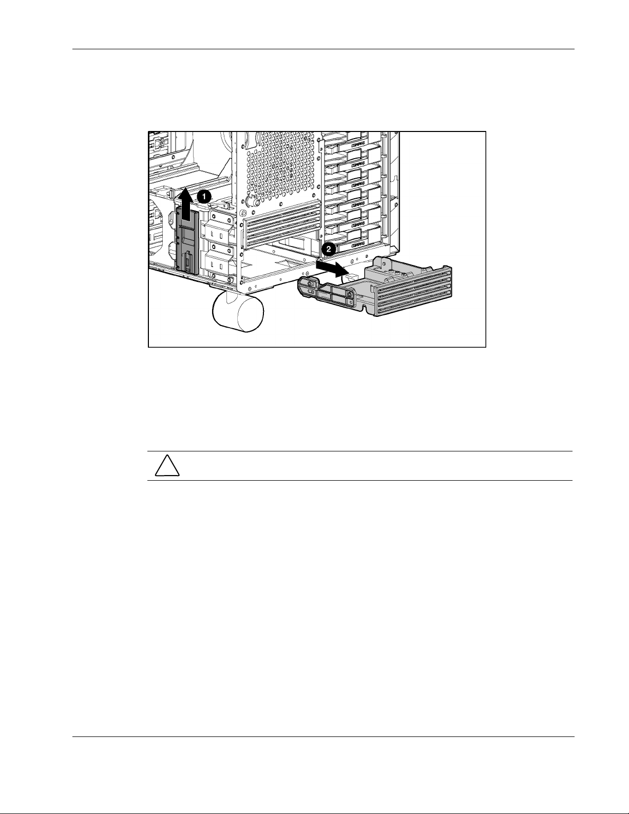
Removal and Replacement Procedures
3. Slide the blue locking lever on the outside of the removable media area to release the
blank (1).
4. Pull the removable media blank from the removable media area (2).
Figure 2-60: Removing a removable media blank from the removable
media area
Reverse steps 1 through 4 to install a removable media blank.
Cable Routing Diagrams
CAUTION: When routing cables, always make sure that the cables are not in a position in
which they can be pinched or crimped.
HP ProLiant ML570 Generation 2 Server Maintenance and Service Guide 2-69
Page 88

Removal and Replacement Procedures
System Board Power Cables
Figure 2-61: System board power cable routing
Drive Fan Power Cables
Figure 2-62: Drive fan power cable routing
2-70 HP ProLiant ML570 Generation 2 Server Maintenance and Service Guide
Page 89

Diskette and CD-ROM Drive Cables
Figure 2-63: Diskette and CD-ROM drive cable routing
Table 2-10: Diskette and CD-ROM Drive Cable Routing
Removal and Replacement Procedures
Item Description
1 Power cable for both diskette and CD-ROM drives
2 Data cable for CD-ROM drive
3 Data cable for diskette drive
SCSI Backplane Power Cables
Figure 2-64: SCSI backplane power cable routing
HP ProLiant ML570 Generation 2 Server Maintenance and Service Guide 2-71
Page 90

Removal and Replacement Procedures
SCSI Cables
Figure 2-65: SCSI cable routing
Table 2-11: SCSI Cable Routing
Item Description
1 SCSI A (blue)
2 SCSI B (yellow)
Figure 2-66: Internal-to-external SCSI cable routing
NOTE: The internal-to-external SCSI cable ships unconnected. If you want to connect it, you must
disconnect one of the drive cages.
2-72 HP ProLiant ML570 Generation 2 Server Maintenance and Service Guide
Page 91

Removal and Replacement Procedures
Table 2-12 lists the cables required for each optional hardware component.
Table 2-12: Required Cables
Component Required Cables Cable ships with:
Power Server Drive cage A
Signal Server
Power Server Drive cage B
Signal Server
Power Server SCSI devices in the removable media bay
Signal Server
Power Server IDE devices in the removable media bay
Signal Option kit
Power Server DVD drive in the CD-ROM bay
Signal Option kit
Power Option kit Remote Insight lights-Out Edition II
Signal Option kit
Front panel LED assembly Power Server
External storage devices Signal Option kit
or option cable kits
External SCSI Signal Server
HP ProLiant ML570 Generation 2 Server Maintenance and Service Guide 2-73
Page 92

Removal and Replacement Procedures
Re-entering the Server Serial Number
After replacing the system tray or clearing the NVRAM, the server serial number must be reentered. To re-enter the serial number:
1. During the server startup sequence, press the F9 key to access RBS
U.
2. Select the System Options menu.
3. Select Serial Number. The following wa
WARNING! WARNING! WARNING! The serial number is loaded into the
system during the manufacturing process and should NOT be
modified. This option should ONLY be used by qualified service
personnel. This value should always match the serial number
sticker located on the chassis.
rning is displayed:
Press the Enter key to clear the warning.
4. Enter the serial number and press the Enter key.
5. Press the Escape key to close the menu.
6. Press
7. Press the F10 key to confir
the Escape key to exit RBSU.
m exiting RBSU. The server will automatically reboot.
2-74 HP ProLiant ML570 Generation 2 Server Maintenance and Service Guide
Page 93

Diagnostic Tools
This chapter is an overview of software and firmware diagnostic tools that are available for
configuring, monitoring, and managing HP ProLiant ML570 Generation 2 servers.
3
HP ProLiant ML570 Generation 2 Server Maintenance and Service Guide 3-1
Page 94

Diagnostic Tools
Use the following tools to diagnose problems, test hardware, and monitor and manage server
operations.
Table 3-1: Diagnostic Tools
Tool Description How to run the tool
Array Diagnostics Utility (ADU) ADU is designed to run on all HP
systems that support HP array
controllers. ADU collects information
about the array controllers in the
system and generates a list of
detected problems.
Automatic Server Recovery-2
(ASR-2)
Diagnostics Utility Diagnostics Utility tests and verifies
ASR-2 automatically restarts the
server after a catastrophic operating
system failure.
With ASR-2, you have multiple
recovery options:
• Available Recovery provides
software error recovery and
environmental recovery.
• Unattended Recovery logs the
error information to the IML,
resets the server, and tries to
restart the operating system.
operation of HP hardware. If the
utility finds a hardware failure, it
isolates the replaceable part, if
possible.
For a list of HP servers that support
ADU, visit
For a complete list of ADU error
messages, refer to the HP Servers
Troubleshooting Guide.
Run RBSU and set ASR-2 to enable
this tool.
Access Diagnostics Utility when
POST detects a system
configuration error. For a complete
list of POST error messages, refer to
the HP Servers Troubleshooting
Guide. Diagnostics Utility can be run
from the SmartStart CD or
downloaded from www.hp.com
www.hp.com.
.
Insight Manager 7 Insight Manager 7 is a client/server
application used to remotely manage
HP hardware in a network
environment. Insight Manager 7
reports hardware fault conditions
(both failure and pre failure) and
collects data for reporting and
graphing.
3-2 HP ProLiant ML570 Generation 2 Server Maintenance and Service Guide
For more information on viewing and
printing the event list, refer to the
Management CD, the HP Insight
Manager User Guide or the HP
ProLiant ML570 Generation 2 Server
Setup and Installation Guide.
continued
Page 95

Table 3-1: Diagnostic Tools continued
Tool Description How to run the tool
Diagnostic Tools
SmartStart SmartStart software is the intelligent
way to set up the HP server. The
SmartStart CD includes the
ROMPaq Utility, driver updates, and
assistance installing operating
systems.
Survey Utility Survey Utility gathers critical
hardware and software information
on servers running Microsoft®
Windows NT®, Novell NetWare,
SCO OpenServer, or SCO Unixware
operating systems.
If a significant change occurs
between data-gathering intervals,
the Survey Utility marks the previous
information and overwrites the
survey text files to reflect the latest
changes in the configuration.
Integrated Management Log (IML) The IML is a log of system events
such as system failures or nonfatal
error conditions. View events in the
IML from within:
• Insight Manager 7
• Survey Utility
• Operating-system-specific IML
utilities
Use the information provided in the
Server Setup and Management
pack.
Install the Survey Utility from the
SmartStart CD, the Integration
Maintenance Utility, or the
Management CD.
The IML requires operating system
management drivers. Refer to the
SmartStart CD for instructions on
installing the appropriate drivers.
ROM-Based Setup Utility (RBSU) RBSU configures the hardware
installed in or connected to the
server. Specifically, it can:
• Store configuration information
in nonvolatile memory
• Manage memory installation,
processor upgrades, network
interface cards and mass
storage devices
• Assist in installing an operating
system
• Configure ports and IRQs, if
required
Run RBSU by pressing the F9 key
during POST.
continued
HP ProLiant ML570 Generation 2 Server Maintenance and Service Guide 3-3
Page 96

Diagnostic Tools
Table 3-1: Diagnostic Tools continued
Tool Description How to run the tool
ROMPaq Utility The ROMPaq Utility checks the
system and provides a choice of
available ROM revisions and
controller firmware.
SmartStart Diskette Builder The SmartStart Diskette Builder is a
utility that uses data stored on the
SmartStart CD to create support
diskettes. You can create support
diskettes for specific configuration
needs or for software that cannot be
used directly from the
SmartStart CD.
Run this utility from the SmartStart
CD incl
Run the diskette builder tool from the
SmartStart CD.
d with the server.
ude
3-4 HP ProLiant ML570 Generation 2 Server Maintenance and Service Guide
Page 97

This chapter explains the location and function of system connectors, internal and external
LEDs, and system board switches.
Connectors
The figures and tables in this chapter show connector locations on the system board, memory
board, and rear panel of an HP ProLiant ML570 Generation 2 server.
4
Connectors, LEDs, and Switches
HP ProLiant ML570 Generation 2 Server Maintenance and Service Guide 4-1
Page 98

Connectors, LEDs, and Switches
System Board
Figure 4-1 and Table 4-1 identify the connectors on the system board of the server.
Figure 4-1: System board connectors
Table 4-1: System Board Connectors
Item Connector
1 Secondary IDE (non-bootable)
2 Remote management (30-pin)
3 Remote management (16-pin)
4 I/O fans
5 System power
6 SCSI A (blue)
7 SCSI B (yellow)
8 Power backplane signal
9 Primary IDE (bootable) (orange)
10 Diskette drive (purple)
11 Processor fans
12 System power
13 PCI backplane
4-2 HP ProLiant ML570 Generation 2 Server Maintenance and Service Guide
Page 99

Memory Board
Figure 4-2 and Table 4-2 identify the slots on the memory boards of the server.
Figure 4-2: DIMM slots
Connectors, LEDs, and Switches
Table 4-2: DIMM slots
Item Slot Bank
1 DIMM slot 1
2 DIMM slot 2
3 DIMM slot 3
4 DIMM slot 4
5 DIMM slot 5
6 DIMM slot 6
7 DIMM slot 7
8 DIMM slot 8
* When the server is configured for online spare memory, Bank
D on memory board 1 is the online spare bank.
Bank A
Bank B
Bank C
Bank D *
HP ProLiant ML570 Generation 2 Server Maintenance and Service Guide 4-3
Page 100

Connectors, LEDs, and Switches
Rear Panel
Figure 4-3 and Table 4-3 identify the connectors on the rear panel of the server.
Figure 4-3: Rear panel connectors
Table 4-3: Rear Panel Connectors
Item Description Item Description
1 Keyboard connector 10 Hot-plug power supply 1
2 Mouse connector 11 Hot-plug power supply 2
3 Serial connector A 12 Torx T-15 tool
4 Parallel connector 13 Unit ID switch and LED
5 Embedded NIC connector (RJ-45) 14 USB connectors
6 Release latch 15 Video connector
7 VHDCI SCSI connector 16 Serial connector B
8 PCI-X Hot Plug expansion slots 17 Hot-plug power supply bay 3 (redundant)
9
PCI-X non-hot-plug expansion slots
4-4 HP ProLiant ML570 Generation 2 Server Maintenance and Service Guide
 Loading...