

HP PROLIANT ML570 User Manual
Technologies for the ProLiant ML570 G3 and ProLiant
DL580 G3 servers
technology brief
Abstract.............................................................................................................................................. 3
Introduction......................................................................................................................................... 3
Processor architecture........................................................................................................................... 3
Defining 64-bit architecture ............................................................................................................... 3
Xeon processor MP .......................................................................................................................... 4
Memory architecture ............................................................................................................................ 5
Background: memory banks and ranks ............................................................................................... 5
Intel E8500 chipset .......................................................................................................................... 6
Partitioning for electrical isolation ................................................................................................... 7
Maximum memory configurations................................................................................................... 7
High-performance memory ................................................................................................................ 7
DDR-2 memory............................................................................................................................. 8
Memory interleaving..................................................................................................................... 8
Errors in memory............................................................................................................................ 11
Hard and soft errors ................................................................................................................... 11
Correctable and uncorrectable errors............................................................................................ 12
Standard ECC............................................................................................................................ 12
Advanced ECC (single device data correction) .............................................................................. 12
Demand scrubbing ..................................................................................................................... 12
High-availability memory technologies.............................................................................................. 13
Hot-plug definitions..................................................................................................................... 13
Online Spare ............................................................................................................................. 13
Hot Plug Mirrored Memory .......................................................................................................... 13
Hot Plug RAID ............................................................................................................................ 14
Comparing Advanced Memory Protection technologies ...................................................................... 14
Ensuring reliability within large-footprint memory designs.................................................................... 15
Architecture trade-offs with a large memory footprint .......................................................................... 16
Updated I/O technologies.................................................................................................................. 17
PCI Express ................................................................................................................................... 17
Smart Array 6i controller................................................................................................................. 18
Mechanical design for serviceability .................................................................................................... 18
Common components ..................................................................................................................... 18

ProLiant ML570 G3........................................................................................................................ 20
ProLiant DL580 G3 ........................................................................................................................ 22
Conclusion........................................................................................................................................ 23
Appendix A. Engineering prefixes ....................................................................................................... 24
For more information.......................................................................................................................... 24
Call to action .................................................................................................................................... 24

Abstract
With the third-generation of ProLiant 500-series servers —the ProLiant ML570 G3 and the ProLiant
DL580 G3 servers — IT managers have additional choices for servers that can transition easily from
32-bit to 64-bit x86 processing. The architecture for the ProLiant ML570 G3 and the DL580 G3 uses
the Intel® 64-bit Xeon™ processor MP designed to operate in either 32-bit or 64-bit mode,
depending on the application and operating system (OS) utilized. This architecture brings enhanced
performance not only through the 64-bit architecture but also through the use of fast DDR-2 memory,
large memory footprints, and dual front-side buses. To complement this high-performing architecture,
the Intel E8500 chipset adds high-availability memory technologies such as Online Spare, Hot Plug
Mirrored memory, and Hot Plug RAID memory. This generation of servers brings Hot Plug RAID
technology — providing the highest level of availability, at a lower cost than mirroring — into the 4way multiprocessing, mid-tier enterprise solution space.
The ProLiant ML570 G3 and the DL580 G3 servers have been completely redesigned to provide
increased serviceability and reliability in their mechanical designs. The chassis designs have minimal
cabling, fool-proof locking mechanisms to avoid mishaps, simple rack rail systems, and are virtually
tool-less.
Introduction
The ProLiant ML570 G3 and the ProLiant DL580 G3 servers bring a new level of high-performance
and high-availability technologies to 4-way, industry-standard servers. Many of these technologies
were previously available only in 8-way x86 servers or servers using other processor architectures.
This brief addresses the following key technologies within the ProLiant ML570 G3 and DL580 G3
platforms:
• The move to 64-bit processor operations
• Faster, higher-performing memory
• High-availability technologies including Advanced Memory Protection technologies and larger
memory footprints
• Updated I/O technologies
• Highly leveraged mechanical designs to ensure serviceability
This brief discusses only certain key technologies of the ProLiant 500-series servers. For complete
specifications of each server, see the HP website at
www.hp.com/go/proliant.
Processor architecture
In 2004, HP introduced the first 4-way ProLiant server to provide 64-bit x86 capabilities —the
ProLiant DL585 using AMD Opteron processors. The ProLiant ML570 G3 and the ProLiant DL580 G3,
announced in March 2005, extend the 64-bit portfolio with their use of the Intel® 64-bit Xeon™
Processor MP with up to 8 MB L3 cache. Its use of Intel Extended Memory 64-bit Technology (EM64T)
enables IT organizations to deploy common platforms for both 32-bit and 64-bit computing, and
move to 64-bit computing gradually as it benefits their businesses.
Defining 64-bit architecture
A 64-bit architecture has a much larger amount of directly addressable (flat) memory space than a
32-bit processor. The use of EM64T allows the OS to access a flat memory address space greater
than 4 GB without enabling Physical Address Extensions (PAE) and incurring the overhead of PAE.
3

This can result in performance advantages for the 64-bit architectures because of their ability to use
large amounts of memory, such as with intensive floating-point calculations used in scientific and
engineering modeling programs.
1
For additional information about 64-bit extensions and architecture, see the technology brief
“
Characterizing x86 processors for industry-standard servers: AMD Opteron and Intel Xeon”
titled
Xeon processor MP
The 64-bit Xeon processor MP comes in two different versions: a version with a 1 MB L2 cache; and a
version with up to 8 MB of L3 cache in addition to the 1 MB L2 cache. Both are built using 90 nm
process technology and use a 166-MHz front side bus which is quad-pumped to 667 MHz, providing
up to 5.3 GB/s of data transfer rates. The processors support IA-32 and the EMT64 instruction set for
running 64-bit applications and operating systems.
As of this writing, the ProLiant ML570 G3 and DL580 G3 platforms support the following processors:
• Xeon MP 3.3 GHz/8 MB L3/1 MB L2
• Xeon MP 3.0 GHz/8 MB L3/1 MB L2
• Xeon MP 2.83 GHz /4MB L3/1 MB L2
• Xeon MP 3.66 GHz/1 MB L2
• Xeon MP 3.16 GHz/1 MB L2
The 64-bit Xeon processor MP uses the NetBurst architecture with Hyper-Threading technology, HyperPipelined technology, and a 12K Execution Trace Cache. It includes support for Enhanced Intel
Speed-Step Technology and Intel Execute Disable Bit technology.
As server and rack densities have increased, power and heat management are becoming
increasingly important. In response, Intel developed Enhanced Intel Speed-Step Technology, which
exposes power state registers in the processor. With the appropriate ROM or OS interface, these
registers can be used to switch the processor between different power states, changing the
processor’s operating frequency and voltage. This, in turn, lowers the power usage and heat
production of the processor. Demand-based switching is the OS implementation of power
management using the Enhanced Speed-Step technology, and is supported by some new operating
systems including Microsoft Windows Server 2003 SP1, Red Hat Enterprise Linux 4 Update 1, and
SUSE Linux Enterprise Server 9 SP1.
2
HP Power Regulator for ProLiant
is an OS–independent power management feature of HP ProLiant
servers that uses Enhanced Speed-Step technology. HP Power Regulator supports both dynamic and
static modes. With HP Static Low Power Mode, the processors are configured to run continuously in a
lower power state. This is useful for customers with power-constrained data centers who require a
guaranteed maximum power usage for each server. For servers that operate in moderately or
minimally loaded environments, there will be little, if any, performance degradation. HP Dynamic
Power Savings mode lowers overall power usage of the server without affecting system performance.
When this feature is enabled,
3
the System ROM will dynamically modify each processor’s frequency
and voltage based on the processor workload. The processor operates in a high power state only
when needed, thus reducing the overall system power usage.
Intel first released the Execute Disable Bit functionality with the Itanium processor family. The
technology allows the processor to classify areas of memory which cannot execute application code.
When combined with OS support, this helps to prevent certain classes of malicious buffer overflow
attacks. As of this writing, Intel Execute Disable bit is supported by Microsoft Windows Server
1
Available on the ISS Technology Papers website at http://h18004.www1.hp.com/products/servers/technology/whitepapers/
2
For additional information about Power Regulator for ProLiant, see http://h18000.www1.hp.com/products/servers/management/ilo/power-
regulator.html
3
The ProLiant ML570 G3 and ML580 G3 system ROMs are expected to support HP Power Regulator mid-year 2005.
4
2003 SP1, Microsoft Windows XP SP2, SuSe Linux Enterprise Server 9.2, or Red Hat Enterprise Linux
3 Update 3.
For additional information about these processors, see the
“
The Intel processor roadmap for industry-standard servers.”
Intel website or the technology brief titled
4
Memory architecture
The ProLiant ML570 G3 and the ProLiant DL580 G3 both use the Intel E8500 chipset architecture,
resulting in the same core technologies for the memory subsystem. However, they differ in their I/O
implementation to meet diverse customer requirements.
Background: memory banks and ranks
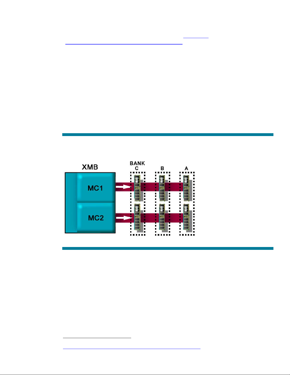
The term memory bank has been used to refer to more than one concept. For this paper, a memory
bank refers to a pair of DIMMs that are located in the same order in two parallel memory channels
(Figure 1). The DIMMs may be single-rank or dual-rank, which affects memory capacity and how
memory is interleaved for performance.
Figure 1. A memory bank is a pair of DIMMs. The ProLiant ML570 G3 has three memory banks; the ProLiant DL580 G3 has
two.
A single-rank DIMM is a DIMM in which all of the memory chips contribute to a single data set of 64
bits (plus the ECC bits) and are activated by the same chip-select signals.
To increase memory density, memory suppliers are producing dual-rank DIMMs. Typically, a dualrank DIMM is made by stacking a second set of memory chips directly on top of the first set of
memory chips. A dual-rank DIMM produces a second data set of 64 bits (plus ECC bits) and requires
two chip-selects with different signals to differentiate between the two sets of memory chips. Although
physically taking up the space of a single DIMM, a dual-rank DIMM acts as if it were two separate
DIMMs, and is considered two electrical loads by the chipset.
4
This technology brief available on the ISS Technology Papers website at
http://h18004.www1.hp.com/products/servers/technology/whitepapers/adv-technology.html
5
Intel E8500 chipset
The E8500 chipset has a high-availability memory subsystem that consists of the North Bridge (TNB)
and the XMB memory controller.
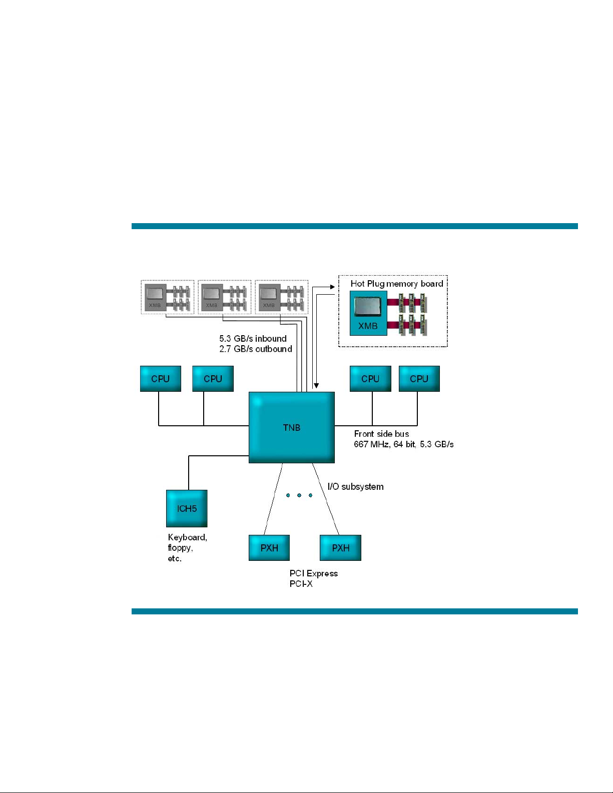
The E8500 chipset is designed to support the upcoming dual-core versions of Intel processors, and
has the important feature of using two separate front side buses to connect to the processors
(Figure 2). Each north bridge can connect to up to four memory boards, and each memory board
includes an XMB memory controller chip. The north bridge connects to each XMB memory controller
using a high-speed serial interconnect (the IMI bus) that allows 5.3 GB/s inbound (for read data
signals from the XMB) and 2.7 GB/s outbound (for write data signals to the XMB). This inbound
speed matches the throughput of the front-side buses, providing a good balance between the
processor and memory subsystem. The north bridge uses an in-order (FIFO) queue to maintain
coherency across the dual front-side buses while processing read/write requests.
Figure 2. Xeon MP architecture used in the ProLiant ML570 G3 and DL580 G3 platforms
Each XMB memory controller chip supports two channels of DDR-2 memory. The DDR-2 memory on
each channel operates in lockstep at 400 MHz. The ProLiant ML570 G3 supports 6 DIMMs per
memory board (three per channel), and the ProLiant DL580 supports 4 DIMMs per memory board
(two per channel), due to physical constraints of the 4U system. For both servers, the maximum
memory supported is 64 GB with 4-GB DIMMs, as described in the section “Maximum memory
configurations.”
6
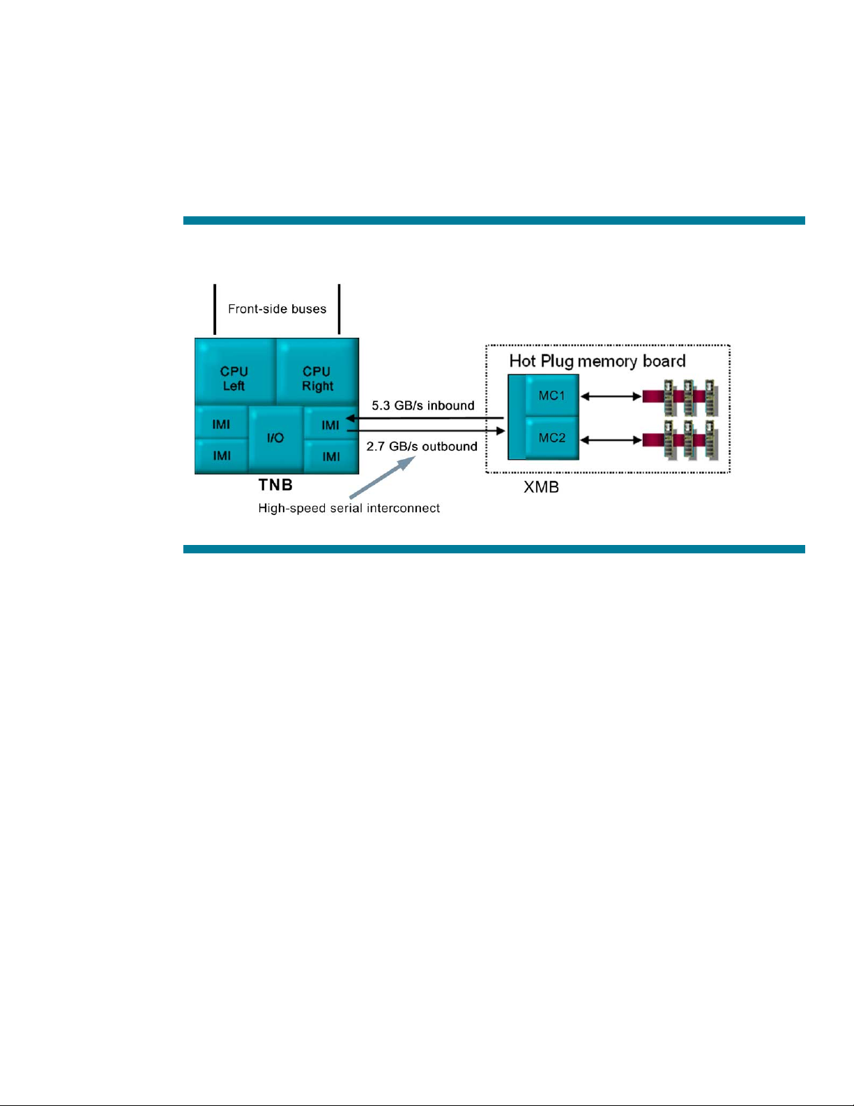
Partitioning for electrical isolation
One of the features of a well-designed chipset is the degree to which the silicon is partitioned to allow
different signal areas to be electrically isolated. The E8500 chipset is partitioned so that the front-side
bus interconnects to a partitioned area for the “left” CPU, the “right” CPU, and each memory board
(Figure 3). The XMB is similarly partitioned so that each internal memory controller is isolated
electrically from the other to avoid power noise and crosstalk issues. Avoiding crosstalk and other
noise is increasingly important as bus speeds increase and bus signals become more susceptible to
slight differences in voltages.
Figure 3. Example of how the TNB and XMB chips are partitioned to reduce power noise and crosstalk issues.
Maximum memory configurations
Each XMB memory controller supports eight electrical loads. A single-rank DIMM is considered one
electrical load; a dual-rank DIMM is two electrical loads. Therefore, the ProLiant ML570 G3 supports
the following maximum DIMM configurations per memory board:
• Six single-rank DIMMs ( three per memory channel)
• Four dual-rank DIMMs (two per memory channel)
• Two dual-rank DIMMS and four singe-rank DIMMs
When 4-GB, dual-rank DIMMs are available, a customer can use four dual-rank DIMMs per memory
board to provide the maximum memory of 64 GB for the ProLiant ML570 G3.
The ProLiant DL580 G3 also supports a maximum of 64 GB of memory using four, dual-rank, 4-GB
DIMMs per memory board. The system can support a maximum of four DIMMs per memory board,
using either single-rank DIMMs, dual-rank DIMMs, or a combination of the two.
In either system, DIMMs must be installed in pairs on the memory board. Each DIMM pair must be
identical, with the same capacity, technology, and density. Refer to the server’s user guide for valid
memory configurations when combining single and dual-rank DIMMs.
High-performance memory
Processor performance has kept pace fairly consistently with Moore’s law of doubling performance
every two years. On the other hand, memory bandwidth doubles roughly every three years. To keep
pace, designers are challenged to make memory subsystems that are faster. The ProLiant ML570 G3
7
and the ProLiant DL580 G3 use DDR2-400 memory and interleaving to improve memory performance
and decrease this performance gap.
DDR-2 memory
DDR-2 SDRAM is the second generation of DDR SDRAM. In contrast to the first generation, DDR-2
memory operates at an even lower voltage (1.8V) to further reduce power consumption; uses higher
clock frequencies to increase data transfer rates, and uses on-die termination control to improve signal
quality. At 200 MHz (double-clocked to an effective 400 MHz), DDR-2 increases memory bandwidth
to 3.2 GB/s.
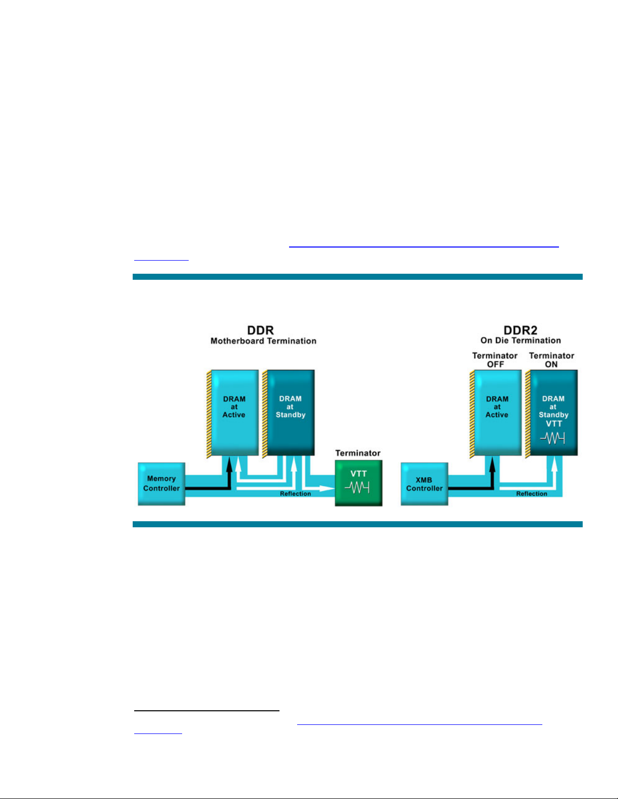
In DDR memory, an external termination resistor is added to the system board to improve signal
quality and reduce noise for the memory signals. This reduces the likelihood of a signal reflecting, or
bouncing back, toward the driving source. DDR-2 memory, on the other hand, moves this resistor into
the silicon of the memory itself. This reduces signal reflection and therefore improves signal quality
(Figure 4).
Refer to the technology brief titled “
Memory technology evolution: an overview of system memory
technologies” for additional information about DDR-2 memory technology.
Figure 4. On-die termination reduces the amount of signal reflection to improve signal quality.
5
Memory interleaving
To reduce latencies and improve performance, there are three different types of memory interleaving
within the ProLiant ML570 G3 and DL580 G3 servers: two-way (dual channel) interleaving,
interleaving within the XMB memory controller, and interleaving across multiple XMB memory
controllers. To simplify the descriptions, the following sections describe how interleaving works when
using single-rank DIMMs. The same concepts apply for dual-rank DIMMs.
5
Available on the ISS Technology papers website at http://h18004.www1.hp.com/products/servers/technology/whitepapers/adv-
technology.html.
8
 Loading...