

Page 1

HP ProLiant ML370 Generation 4 Server
Reference and Troubleshooting Guide
May 2005 (Second Edition)
Part Number 346896-002
Page 2

© Copyright 2004, 2005 Hewlett-Packard Development Company, L.P.
The information contained herein is subject to change without notice. The only warranties for HP products
and services are set forth in the express limited warranty statements accompanying such products and
services. Nothing herein should be construed as constituting an additional warranty. HP shall not be liable
for technical or editorial errors or omissions contained herein.
Microsoft, Windows, and Windows NT are US registered trademarks of Microsoft Corporation.
Linux is a U.S. registered trademark of Linus Torvalds.
HP ProLiant ML370 Generation 4 Server Reference and Troubleshooting Guide
May 2005 (Second Edition)
Part Number 346896-002
Audience assumptions
This document is for the person who installs, administers, and troubleshoots servers and storage
systems. HP assumes you are qualified in the servicing of computer equipment and trained in
recognizing hazards in products with hazardous energy levels.
Page 3

3
Contents
Server component identification 9
Front panel components....................................................................................................................... 9
Front panel LEDs and buttons............................................................................................................10
Rear panel components...................................................................................................................... 12
Rear panel LEDs and buttons.............................................................................................................13
System board components .................................................................................................................14
System maintenance switch....................................................................................................15
DIMM slots.............................................................................................................................17
System board LEDs ...........................................................................................................................18
Power supply backplane LED............................................................................................................ 19
System LEDs and internal health LED combinations........................................................................ 19
SCSI IDs and SAS-SATA device numbers........................................................................................21
SCSI configurations........................................................................................................................... 22
Hot-plug SCSI hard drive LEDs........................................................................................................ 22
Hot-plug SCSI hard drive LED combinations ................................................................................... 23
SATA or SAS hard drive LEDs.........................................................................................................24
SAS and SATA hard drive LED combinations..................................................................................25
Identifying redundant hot-plug fans...................................................................................................26
Server operations 27
Powering up the server.......................................................................................................................27
Powering down the server.................................................................................................................. 27
Extending the server from the rack.................................................................................................... 28
Unlocking the front tower bezel.........................................................................................................29
Removing the access panel ................................................................................................................30
Server setup 31
Optional installation services.............................................................................................................31
Rack planning resources ....................................................................................................................32
Optimum environment....................................................................................................................... 33
Space and airflow requirements..............................................................................................33
Temperature requirements......................................................................................................34
Power requirements................................................................................................................ 35
Electrical grounding requirements..........................................................................................36
Rack warnings and cautions............................................................................................................... 36
Identifying rack server shipping carton contents ...............................................................................39
Identifying tower server shipping carton contents............................................................................. 39
Page 4

4 HP ProLiant ML370 Generation 4 Server Reference and Troubleshooting Guide
Installing hardware options................................................................................................................40
Setting up a tower server....................................................................................................................40
Installing the server into the rack.......................................................................................................42
Powering up and configuring the server ............................................................................................50
Installing the operating system...........................................................................................................50
Registering the server.........................................................................................................................51
Hardware options installation 53
Introduction........................................................................................................................................ 53
Processor options ............................................................................................................................... 54
Memory options................................................................................................................................. 58
Online spare memory configuration .......................................................................................58
DIMM installation guidelines................................................................................................. 59
Installing DIMMs ...................................................................................................................59
Hot-plug SCSI hard drive options......................................................................................................60
Removing a hot-plug SCSI hard drive....................................................................................60
Installing a hot-plug SCSI hard drive .....................................................................................61
SAS-SATA hard drive cage............................................................................................................... 62
Removing the hard drive cage ................................................................................................62
Installing the SAS-SATA hard drive cage.............................................................................. 64
Removable media devices.................................................................................................................. 67
Accessing the removable media cage..................................................................................... 68
Installing a half-height or full-height media device................................................................ 70
Installing an optional internal two-bay hot-plug SCSI drive cage..........................................73
Redundant hot-plug fans....................................................................................................................75
Redundant hot-plug fan cage option.......................................................................................76
Installing hot-plug fans........................................................................................................... 78
Replacing hot-plug fans..........................................................................................................80
Redundant hot-plug power supply .....................................................................................................80
Expansion boards............................................................................................................................... 82
Performance balancing ...........................................................................................................83
Removing the expansion slot cover........................................................................................83
Installing expansion boards ....................................................................................................84
Remote Insight Lights-Out Edition II board......................................................................................86
VHDCI or HD68 SCSI cable option..................................................................................................87
Duplex SCSI board option .................................................................................................................89
Tower-to-rack conversion option....................................................................................................... 90
Converting a tower server to a rack server .............................................................................90
Installing the rack server.........................................................................................................97
Accessing the server in the rack ............................................................................................. 97
Server cabling 99
Storage device cabling guidelines......................................................................................................99
Hot-plug SCSI cabling.......................................................................................................................99
Page 5

Contents 5
Integrated simplex SCSI cabling ..........................................................................................100
Integrated duplex SCSI cabling............................................................................................ 101
Array controller simplex SCSI cabling................................................................................. 102
Array controller duplex SCSI cabling ..................................................................................102
Integrated SCSI cabling with optional internal two-bay hot-plug SCSI drive cage..............104
Array controller SCSI cabling with optional internal two-bay hot-plug SCSI drive cage....105
Cable connector identification ......................................................................................................... 106
CD-ROM drive cabling....................................................................................................................107
RILOE II cabling .............................................................................................................................107
Diskette drive cabling ......................................................................................................................108
External storage cabling...................................................................................................................109
Server configuration and utilities 111
Configuration tools ..........................................................................................................................111
SmartStart software ..............................................................................................................111
HP ROM-Based Setup Utility ..............................................................................................113
Array Configuration Utility ..................................................................................................115
Option ROM configuration for arrays ..................................................................................115
Option ROM configuration for arrays ..................................................................................116
Auto-configuration process ..................................................................................................117
HP ProLiant Essentials Rapid Deployment Pack .................................................................118
Re-entering the server serial number and product ID........................................................... 118
Management tools............................................................................................................................119
Automatic server recovery....................................................................................................119
ROMPaq utility.....................................................................................................................119
System Online ROM flash component utility.......................................................................120
Integrated Lights-Out technology.........................................................................................120
StorageWorks library and tape tools..................................................................................... 122
Management agents.............................................................................................................. 122
HP Systems Insight Manager................................................................................................123
Redundant ROM support......................................................................................................123
USB support .........................................................................................................................124
Diagnostic tools ...............................................................................................................................125
Survey Utility .......................................................................................................................125
Array Diagnostic Utility .......................................................................................................126
HP Insight Diagnostics .........................................................................................................126
Integrated management log...................................................................................................126
Keeping the system current.............................................................................................................. 127
Drivers.................................................................................................................................. 127
Resource Paqs....................................................................................................................... 128
ProLiant Support Packs ........................................................................................................ 128
ActiveUpdate........................................................................................................................ 128
Operating system version support.........................................................................................128
Page 6

6 HP ProLiant ML370 Generation 4 Server Reference and Troubleshooting Guide
Change control and proactive notification............................................................................ 129
Natural language search assistant .........................................................................................129
Care Pack.............................................................................................................................. 129
Troubleshooting 131
Server diagnostic steps..................................................................................................................... 131
Important safety information ................................................................................................131
Preparing the server for diagnosis ........................................................................................135
Symptom information...........................................................................................................136
Diagnostic steps.................................................................................................................... 137
Procedures for all ProLiant servers..................................................................................................151
Hardware problems...............................................................................................................151
Software problems................................................................................................................177
Contacting HP.......................................................................................................................186
Error messages................................................................................................................................. 192
ADU error messages.............................................................................................................192
POST error messages and beep codes ..................................................................................225
Event list error messages ......................................................................................................278
HP BladeSystem infrastructure error codes.......................................................................... 283
Battery replacement 293
Regulatory compliance notices 295
Regulatory compliance identification numbers................................................................................295
Federal Communications Commission notice..................................................................................296
FCC rating label....................................................................................................................296
Class A equipment................................................................................................................ 296
Class B equipment................................................................................................................ 297
Declaration of conformity for products marked with the FCC logo, United States only.................297
Modifications ...................................................................................................................................298
Cables...............................................................................................................................................298
Mouse compliance statement........................................................................................................... 298
Canadian notice (Avis Canadien).....................................................................................................298
European Union Notice.................................................................................................................... 299
Japanese notice.................................................................................................................................300
BSMI notice..................................................................................................................................... 300
Laser compliance .............................................................................................................................300
Battery replacement notice...............................................................................................................301
Taiwan battery recycling notice....................................................................................................... 302
Power cord statement for Japan ....................................................................................................... 302
Electrostatic discharge 303
Preventing electrostatic discharge.................................................................................................... 303
Grounding methods to prevent electrostatic discharge ....................................................................304
Page 7

Contents 7
Server specifications 305
Server specifications ........................................................................................................................305
Environmental specifications........................................................................................................... 305
Technical support 307
Related documents........................................................................................................................... 307
HP contact information.................................................................................................................... 307
Before you contact HP..................................................................................................................... 308
Customer self repair......................................................................................................................... 308
Acronyms and abbreviations 309
Index 313
Page 8

Page 9
9
Server component identification
In this section
Front panel components..................................................................................................................9
Front panel LEDs and buttons......................................................................................................10
Rear panel components.................................................................................................................12
Rear panel LEDs and buttons .......................................................................................................13
System board components............................................................................................................14
System board LEDs......................................................................................................................18
Power supply backplane LED ......................................................................................................19
System LEDs and internal health LED combinations ..................................................................19
SCSI IDs and SAS-SATA device numbers..................................................................................21
Hot-plug SCSI hard drive LEDs...................................................................................................22
Hot-plug SCSI hard drive LED combinations..............................................................................23
SATA or SAS hard drive LEDs ...................................................................................................24
SAS and SATA hard drive LED combinations ............................................................................25
Identifying redundant hot-plug fans .............................................................................................26
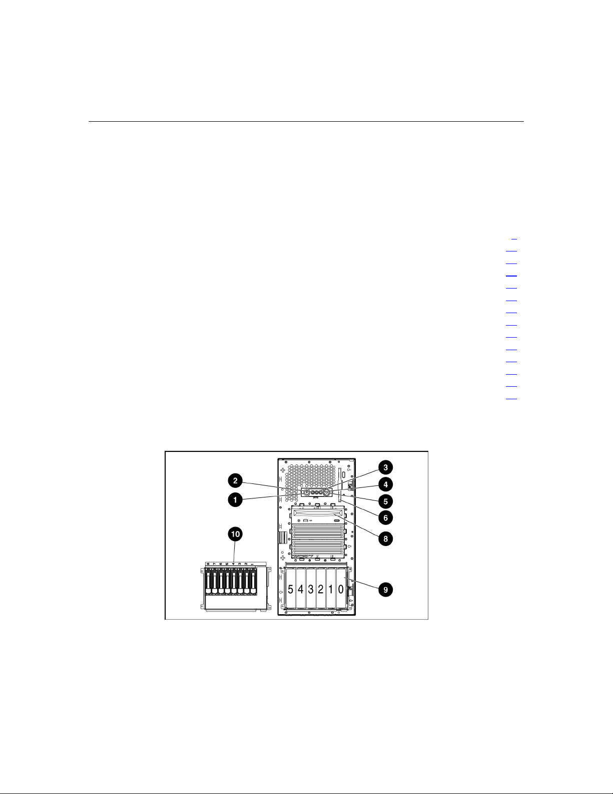
Front panel components
Page 10
10 HP ProLiant ML370 Generation 4 Server Reference and Troubleshooting Guide
Item Description
1 UID switch and LED
2 Internal system health LED
3 Front panel USB port
4 External system health LED
5 NIC link/activity LED
6 Power on/Standby button/LED assembly
7 Diskette drive*
8 Removable media bays
9 Hot-plug SCSI hard drive bays (SCSI IDs 0 through 5)
10 Optional SAS-SATA hard drive bays (1 through 8)
* Open the media door on the rack server to access the diskette drive.
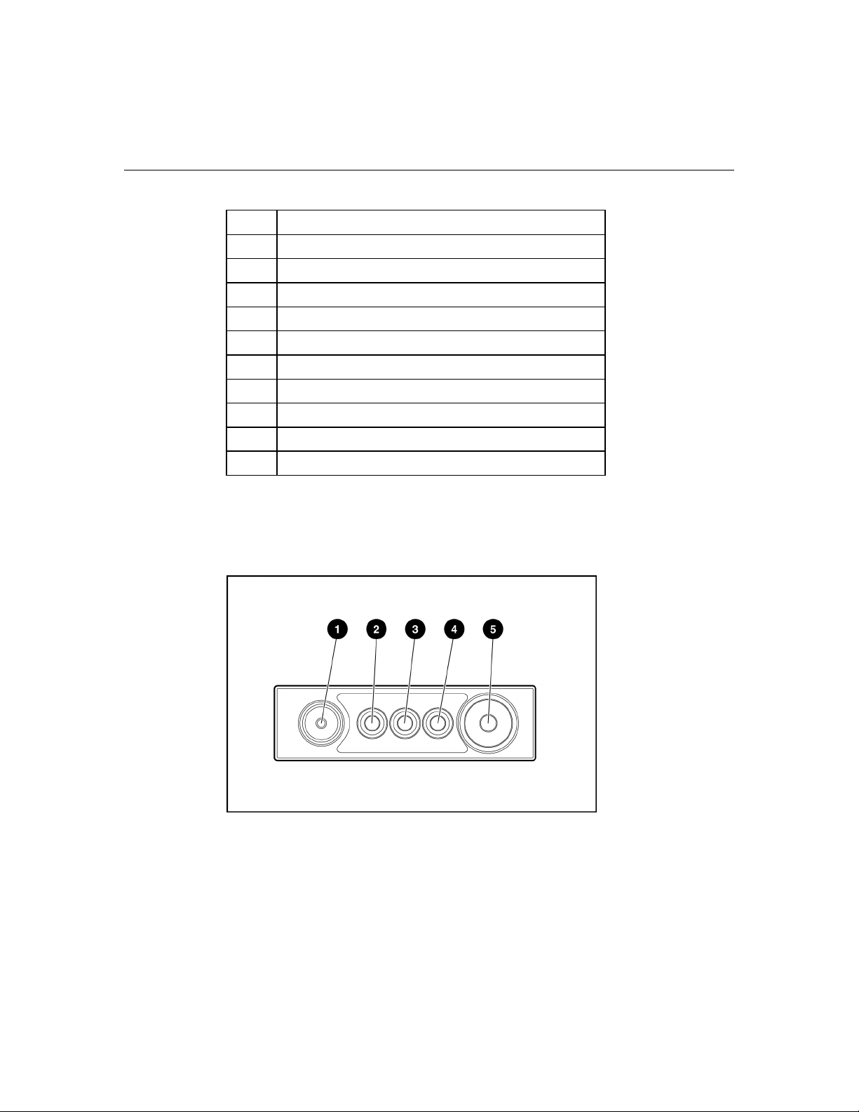
Front panel LEDs and buttons
Page 11

Server component identification 11
Item Description Status
1 UID switch and LED Blue = Activated
Flashing blue = System being managed remotely
Off = Deactivated
2 Internal system health
LED
3 External system health
(power supply) LED
4 NIC link/activity LED
(embedded NIC only)
5 Power on/Standby button
and LED
Green = Normal (system on)
Amber = System health is degraded
Red = System health is critical
Off = Normal (system off)
Green = Normal (system on)
Amber = Redundant power supply failure
Red = Power supply failure. No operational power supplies.
Off = Normal (system off)
Green = Linked to network
Flashing green = Linked with activity on the network
Off = No network connection
Amber = System has AC power and is in standby mode
Green = System has AC power and is turned on
Off = System has no AC power
Page 12
12 HP ProLiant ML370 Generation 4 Server Reference and Troubleshooting Guide
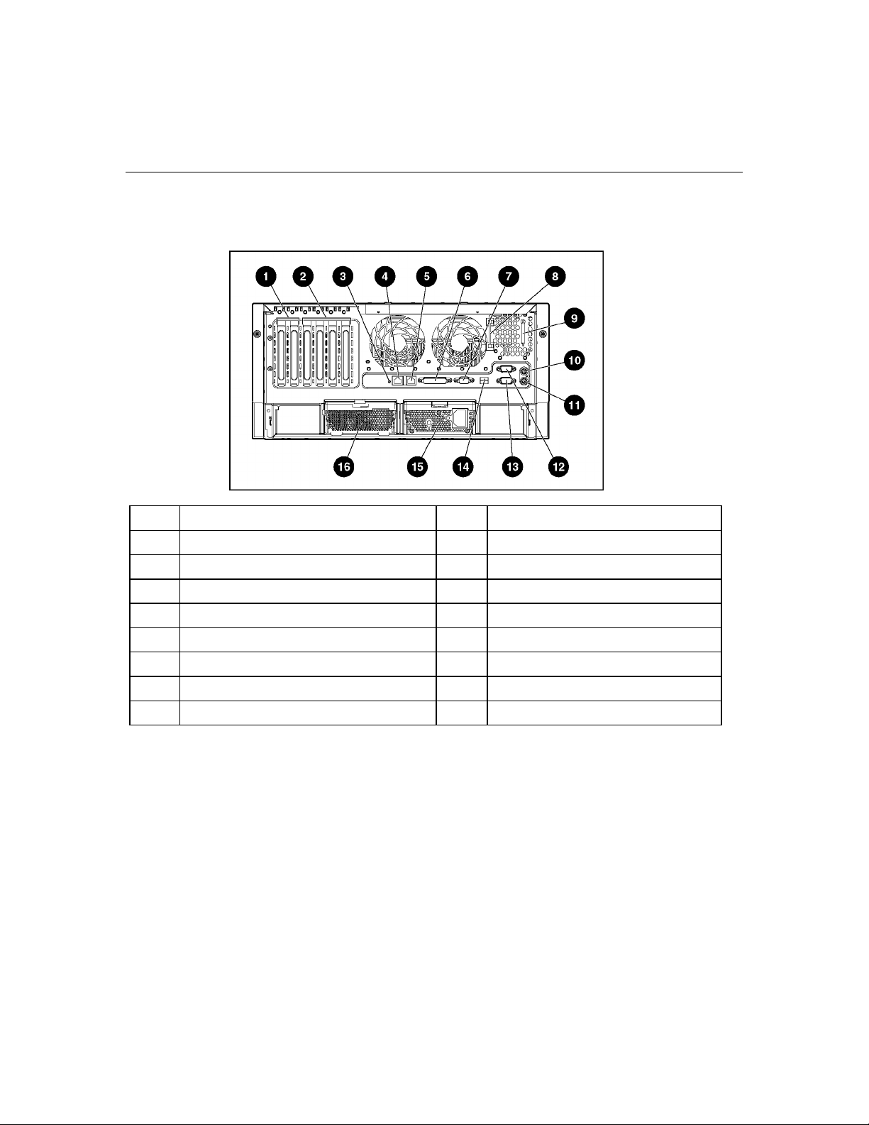
Rear panel components
Item Description Item Description
1 x4 PCI Express expansion slots 9 Auxillary VHDCI SCSI blank
2 100-MHz PCI-X expansion slots 10 Mouse connector
3 Unit ID LED 11 Keyboard connector
4 Ethernet 10/100/1000 port 12 Serial connector B
5 iLO management port 13 Serial connector A
6 Parallel connector 14 USB connectors
7 Video connector 15 Primary hot-plug power supply
8 T-15 Torx screwdriver 16 Redundant hot-plug power supply
Page 13
Server component identification 13
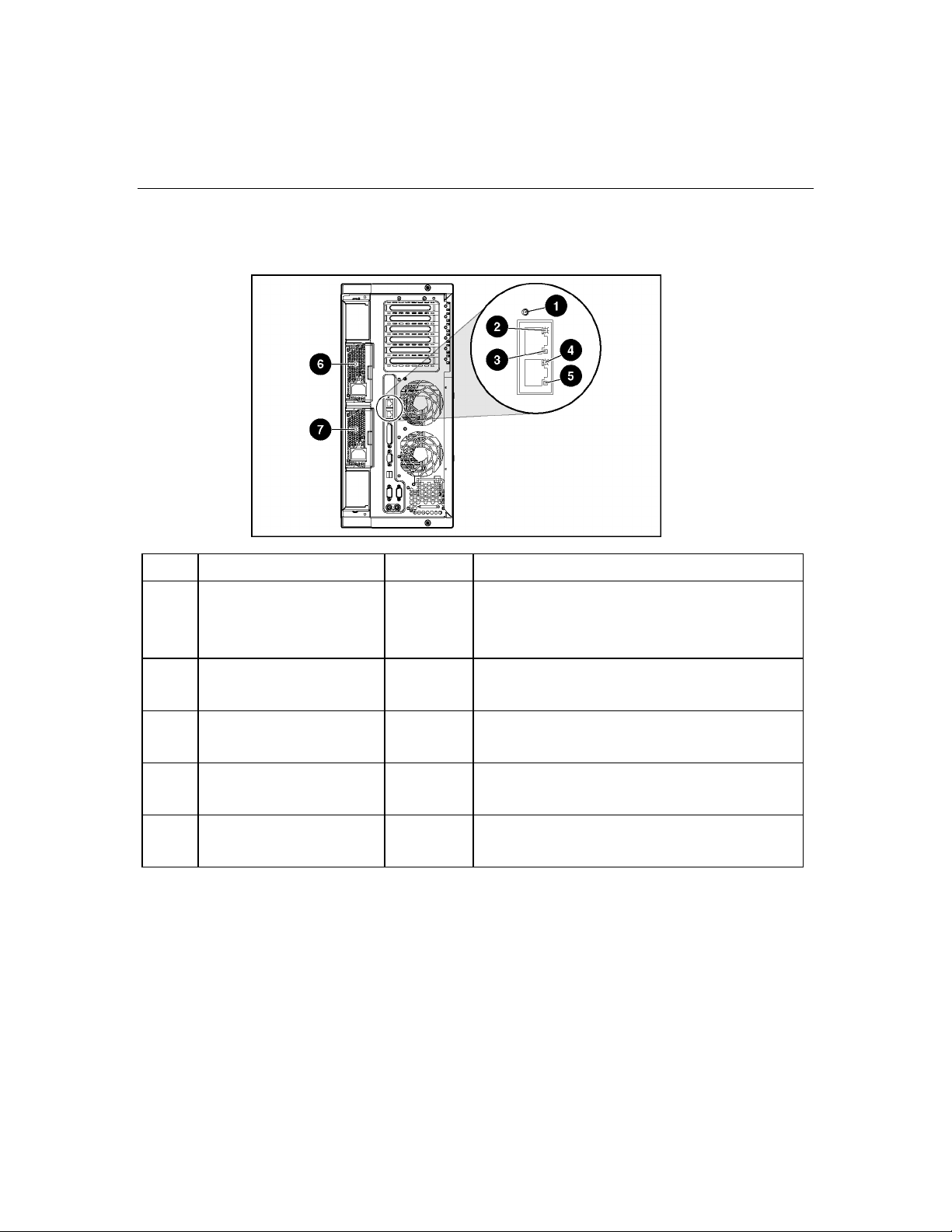
Rear panel LEDs and buttons
Item Description LED Color Status
1 Unit ID LED Blue On = Activated
Flashing = System remotely managed
Off = Deactivated
2 NIC Activity LED
(Integrated NC7781)
3 NIC Link LED
(Integrated NC7781)
4 iLO NIC Activity LED Green On or flashing = Network activity
5 iLO NIC Link LED Green On = Linked to network
Green On or flashing = Linked to network
Off = Not linked to network
Green On = Network activity
Off = No network activity
Off = No network activity
Off = Not linked to network
Page 14
14 HP ProLiant ML370 Generation 4 Server Reference and Troubleshooting Guide
Item Description LED Color Status
6 Power supply LED
Green On = Power turned on and power supply
(redundant)
7 Power Supply LED
Green On = Power turned on and power supply
(primary)
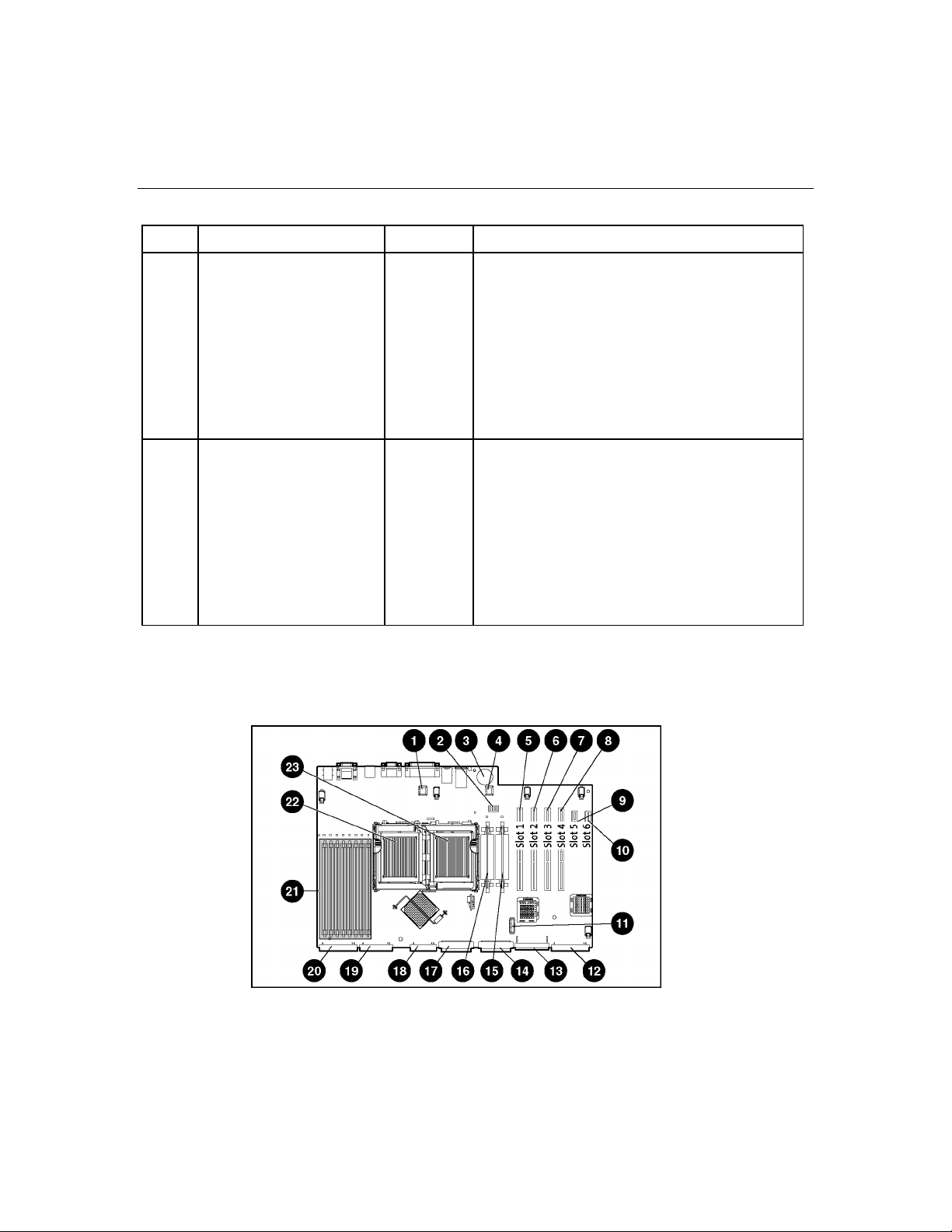
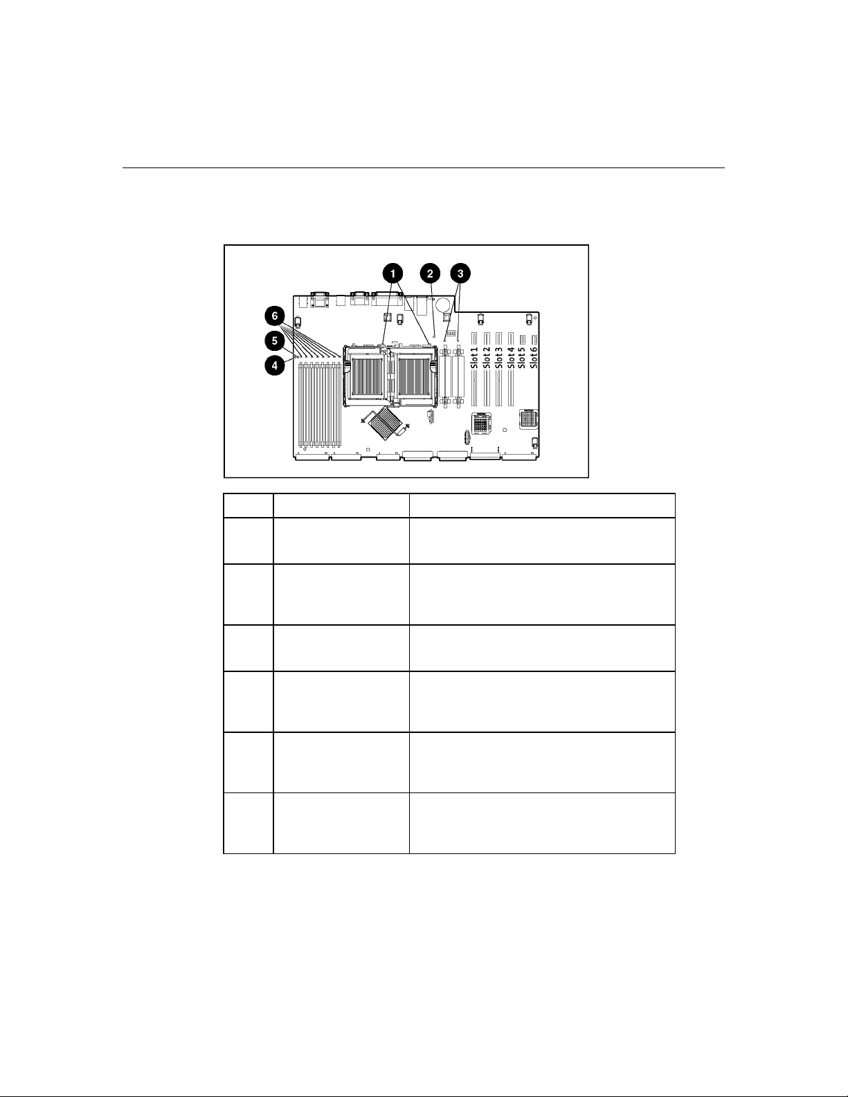
System board components
functioning properly
Off = One or more of the following conditions
exists:
•
AC power unavailable
•
Power supply failed
•
Power supply in standby mode
•
Power supply exceeded current limit
functioning properly
Off = One or more of the following conditions
exists:
•
AC power unavailable
•
Power supply failed
•
Power supply in standby mode
•
Power supply exceeded current limit
Page 15
Server component identification 15
Item Description Item Description
1 Redundant fan 2 connector 13 Power supply connector
2 System maintenance switch 14 SCSI port 1
3 System battery 15 PPM socket 2
4 Redundant fan 4 connector 16 PPM socket 1 (populated)
5 64-bit/100-MHz PCI-X slot,
17 SCSI port 2
bus 3
6 64-bit/100-MHz PCI-X slot,
18 Fan cable connector
bus 3
7 64-bit/100-MHz PCI-X slot,
19 Diskette drive connector
bus 7
8 64-bit/100-MHz PCI-X slot,
20 IDE connector
bus 7
9 PCI Express x4 slot, bus
21 DIMM slots
11 *
10 PCI Express x4 slot, bus
22 Processor 1
14 *
11 RILOE II connector (install
23 Processor 2
adapter into slot 1) **
12 Power supply signal
connector
* x8 PCI Express cards are supported, but will run at x4 speeds.
** The server comes with iLO remote management capability embedded on the system
board. The 30-pin remote management connector for the RILOE II board is provided if the
server environment requires an upgrade for improved Remote Console performance.
System maintenance switch
The system maintenance switch (SW1) is a six-position switch that is used for
system configuration. The default position for all six positions is Off.
Page 16
16 HP ProLiant ML370 Generation 4 Server Reference and Troubleshooting Guide
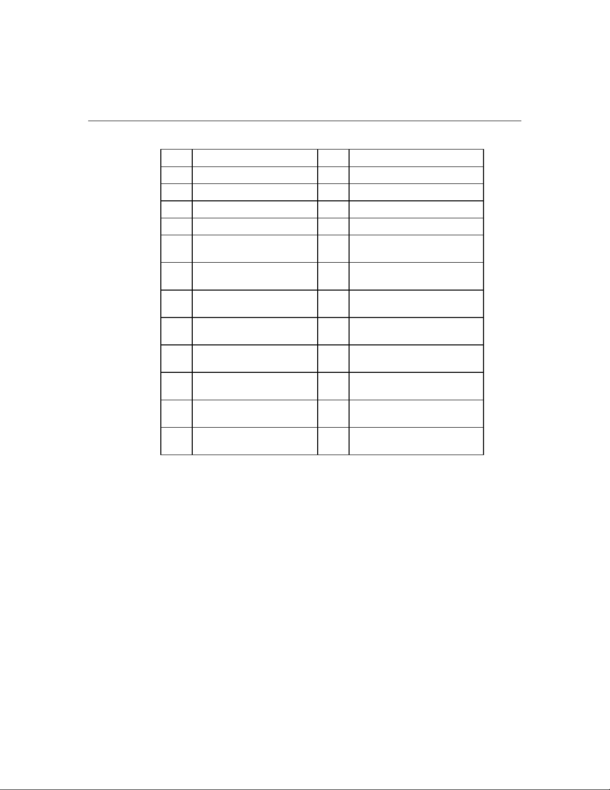
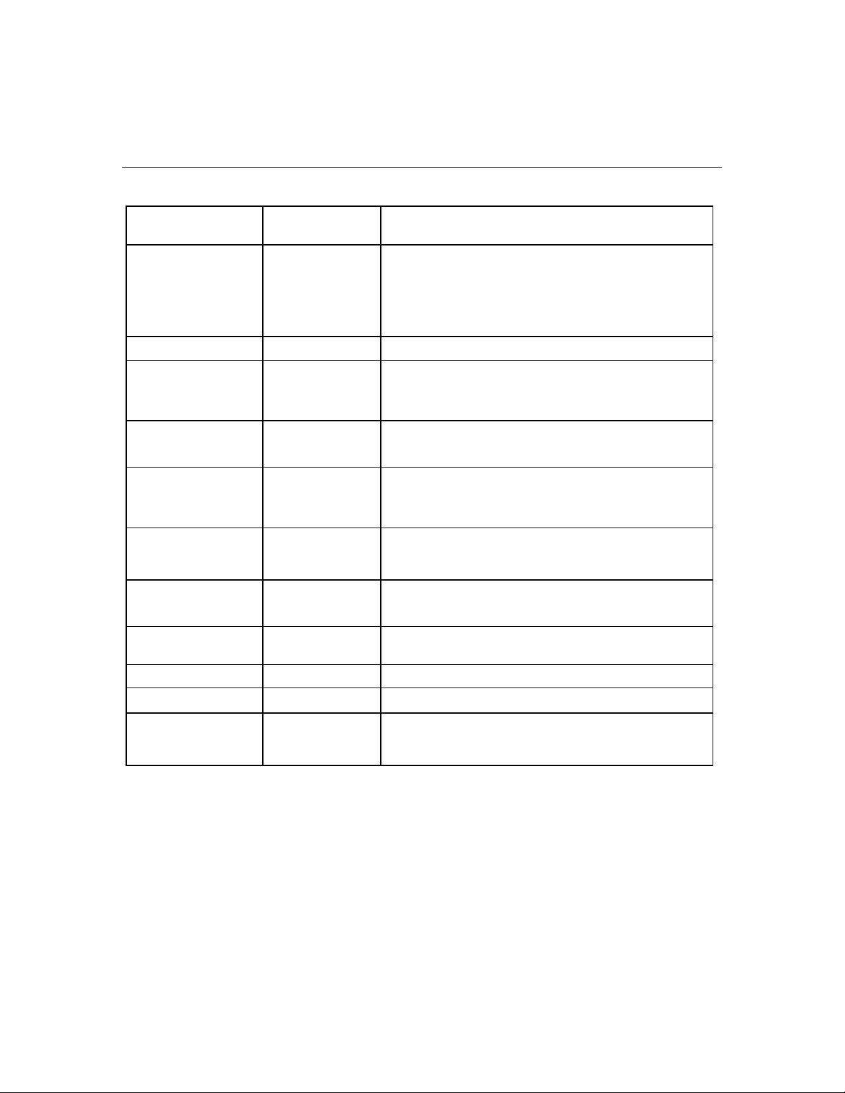
Position Description Function
S1 iLO Security Off = iLO security is enabled
On = iLO security is disabled
S2 Configuration
lock
Off = System configuration can
be changed
On = System configuration is
locked
S3 Reserved Reserved
S4 Reserved Reserved
S5 Password
protection
override
Off = No function
On = Clears power-on
password and administrator
password
S6 Invalidate
configuration
Off = Normal
On = ROM treats system
configuration as invalid
When the system maintenance switch position 6 is set to the On position, the
system is prepared to erase all system configuration settings from both CMOS
and NVRAM.
CAUTION: Clearing CMOS and/or NVRAM deletes
configuration information. Be sure to properly configure the server or
data loss could occur.
Page 17
Server component identification 17
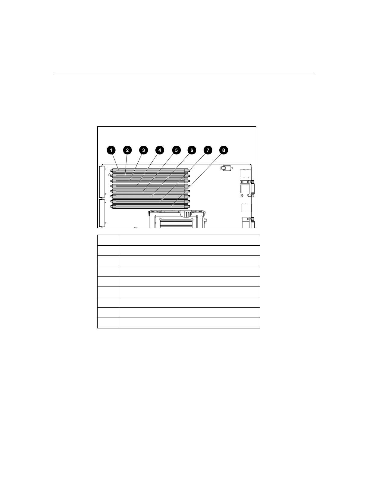
DIMM slots
DIMM slots are numbered sequentially (1 through 8) and the paired banks are
identified by the letters A, B, C, and D.
Item Description
1 DIMM slot 1A
2 DIMM slot 2A
3 DIMM slot 3B
4 DIMM slot 4B
5 DIMM slot 5C
6 DIMM slot 6C
7 DIMM slot 7D
8 DIMM slot 8D
Page 18
18 HP ProLiant ML370 Generation 4 Server Reference and Troubleshooting Guide
System board LEDs
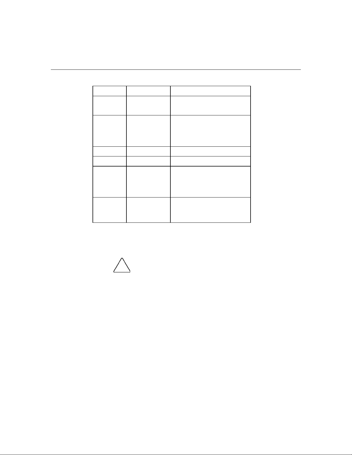
Item LED Description Status
1 Processor error Off = Normal
Amber = Processor failed or missing
2 System temperature
alert
Off = Normal
Amber = System temperature has exceeded
OS cautionary level
3 PPM error Off = Normal
Amber = PPM failed or missing
4 Memory mode LED Off = Normal
Green = System is in online spare memory
mode
5 Online spare memory
failover LED
Off = Normal
Amber = Online spare memory is in use due
to memory failover
6 Memory status Off = Normal
Amber = Memory failed or configuration
problem
Page 19
Server component identification 19
Power supply backplane LED
If the power supply backplane LED is illuminated, then the power supply
backplane must be replaced.
System LEDs and internal health LED combinations
When the internal health LED on the front panel illuminates either amber or red,
the server is experiencing a health event. Combinations of illuminated system
LEDs and the internal health LED indicate system status.
NOTE: The system management driver must be installed in order for
the internal health LED to provide pre-failure and warranty conditions.
The front panel health LEDs indicate only the current hardware status. In some
situations, HP SIM may report server status differently than the health LEDs
because the software tracks more system attributes.
Page 20
20 HP ProLiant ML370 Generation 4 Server Reference and Troubleshooting Guide
System LED and
Color
Internal Health
LED Color
Status
Processor failure,
socket X (Amber)
Red One or more of the following conditions may exist:
•
Processor in socket X has failed.
•
Processor X is not installed in the socket.
•
ROM detected a failed processor during POST.
Amber Processor in socket X is in a pre-failure condition.
PPM failure, slot X
(Amber)
Red • • PPM in slot X has failed.
PPM is not installed in slot X, but the corresponding
processor is installed.
DIMM failure, slot X
(Amber)
Red • • DIMM in slot X has failed.
DIMM has experienced a multi-bit error.
Amber • • DIMM in slot X has reached single-bit correctable
error threshold.
DIMM in slot X is in a pre-failure condition.
DIMM bank error (all
slots in one bank,
Red The bank is not populated entirely or DIMMs do not all
match within the bank.
Amber)
DIMM failure (all
slots, Amber)
System temperature
alert (Amber)
Red • • No valid or usable memory is installed in the system.
The banks are not populated in the correct order.
Red System temperature has exceeded OS cautionary level
or critical hardware level.
Fan (Amber) Red A required fan has failed.
Power supply
Amber A redundant fan has failed.
Red The power supply backplane has failed.
backplane failure
(Amber)
Page 21
Server component identification 21
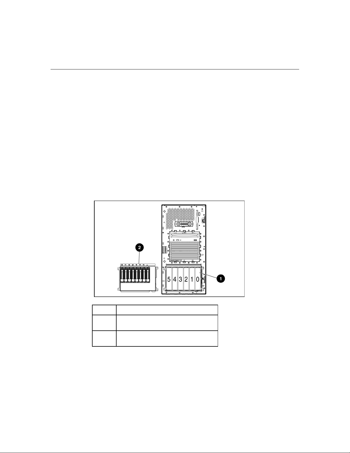
SCSI IDs and SAS-SATA device numbers
The server supports single- or dual-channel SCSI hard drive configurations. The
single-channel configuration (simplex) supports up to six hard drives on SCSI
channel 1. The dual-channel configuration (duplex) supports two hard drives on
SCSI channel 2 (SCSI IDs 4 and 5), and up to four hard drives on SCSI channel
1 (SCSI IDs 0 through 3).
The server supports a combination of up to eight SAS and SATA hard drives in
the optional SAS-SATA hard drive cage. SAS-SATA devices are numbered 1
through 8.
The SCSI IDs for both simplex and duplex configurations, as well as SAS-SATA
device numbers, are illustrated. HP recommends populating hard drive bays
starting with the lowest SCSI ID or device number.
Item Description
1 SCSI hard drive cage (SCSI IDs 0
through 5)
2 SAS-SATA hard drive cage (Device
numbers 1 through 8)
Page 22
22 HP ProLiant ML370 Generation 4 Server Reference and Troubleshooting Guide
SCSI configurations
NOTE: These SCSI ID designations apply regardless of the controller
or the configuration used.
NOTE: The standard cabling configuration for the server is simplex.
Duplex is an option requiring the duplex kit. Refer to "Server Cabling
(on page 99
Configuration Channel 1 Channel 2
)" for cabling information.
Simplex SCSI IDs 0, 1, 2, 3,
4, 5
Duplex SCSI IDs 0, 1, 2, 3 SCSI IDs 4, 5
IMPORTANT: After changing any SCSI configuration, be sure the
proper boot controller order is set in RBSU.
Unused
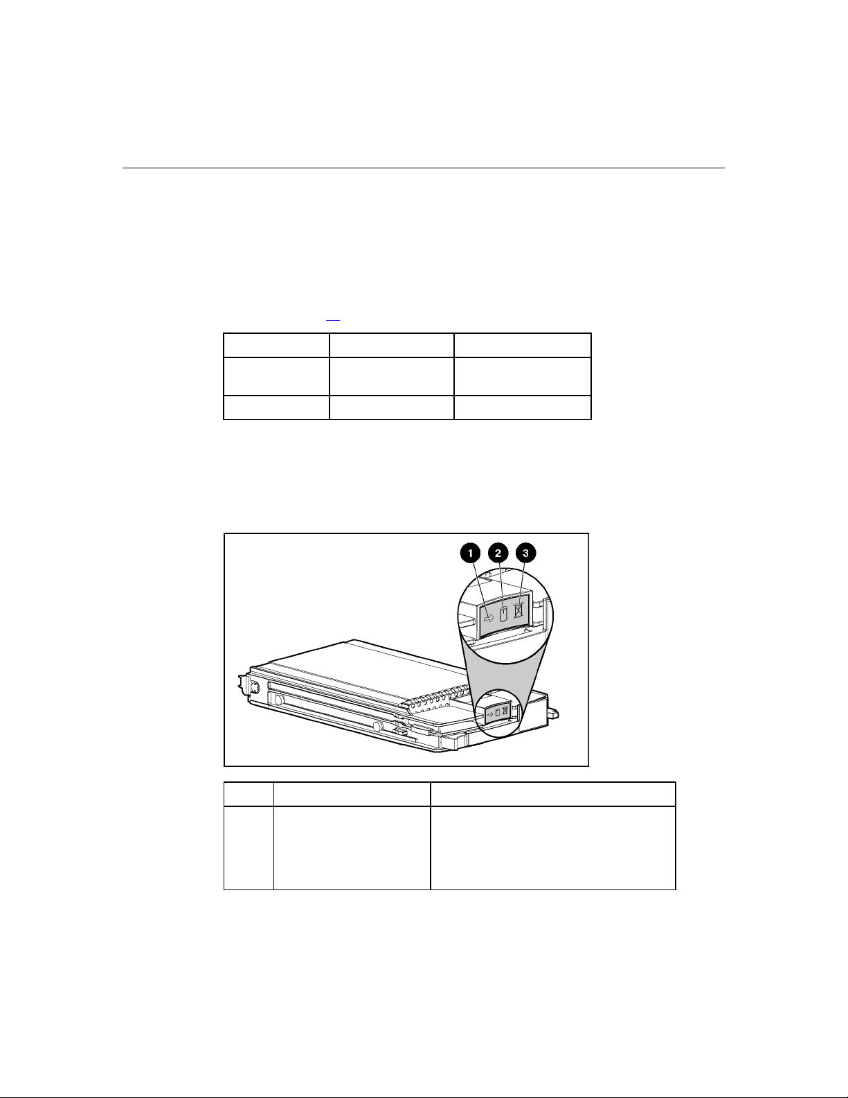
Hot-plug SCSI hard drive LEDs
Item LED Description Status
1 Activity status On = Drive activity
Flashing = High activity on the drive or drive
is being configured as part of an array.
Off = No drive activity
Page 23
Server component identification 23
Item LED Description Status
2 Online status On = Drive is part of an array and is
currently working.
Flashing = Drive is actively online.
Off = Drive is offline.
3 Fault status On = Drive failure
Flashing = Fault-process activity
Off = No fault-process activity
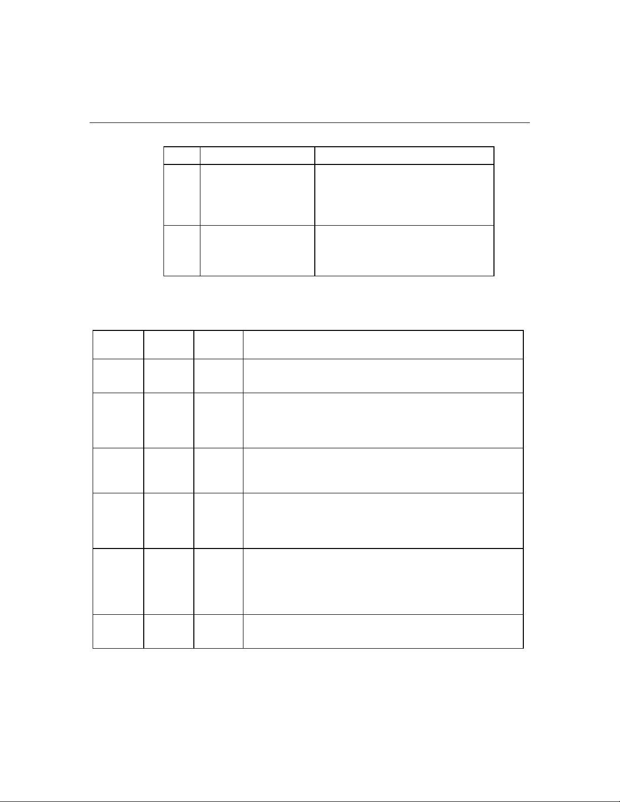
Hot-plug SCSI hard drive LED combinations
Activity
LED (1)
Online
LED (2)
Fault LED
(3)
Interpretation
On, off, or
flashing
On, off, or
flashing
On or off Flashing A predictive failure alert has been received for this drive.
Replace the drive as soon as possible.
On Off The drive is online and is configured as part of an array.
If the array is configured for fault tolerance and all other drives in the
array are online, and a predictive failure alert is received or a drive
capacity upgrade is in progress, you may replace the drive online.
On or
flashing
Flashing Off
Do not remove the drive. Removing a drive may terminate the
current operation and cause data loss.
The drive is rebuilding or undergoing capacity expansion.
On Off Off
Do not remove the drive.
The drive is being accessed, but (1) it is not configured as part of an
array; (2) it is a replacement drive and rebuild has not yet started; or
(3) it is spinning up during the POST sequence.
Flashing Flashing Flashing
Do not remove the drive. Removing a drive may cause data loss
in non-fault-tolerant configurations.
Either (1) the drive is part of an array being selected by an array
configuration utility; (2) Drive Identification has been selected in
HP SIM; or (3) drive firmware is being updated.
Off Off On The drive has failed and has been placed offline.
You may replace the drive.
Page 24
24 HP ProLiant ML370 Generation 4 Server Reference and Troubleshooting Guide
Activity
LED (1)
Online
LED (2)
Fault LED
(3)
Interpretation
Off Off Off Either (1) the drive is not configured as part of an array; (2) the drive
is configured as part of an array, but it is a replacement drive that is
not being accessed or being rebuilt yet; or (3) the drive is configured
as an online spare.
If the drive is connected to an array controller, you may replace the
drive online.
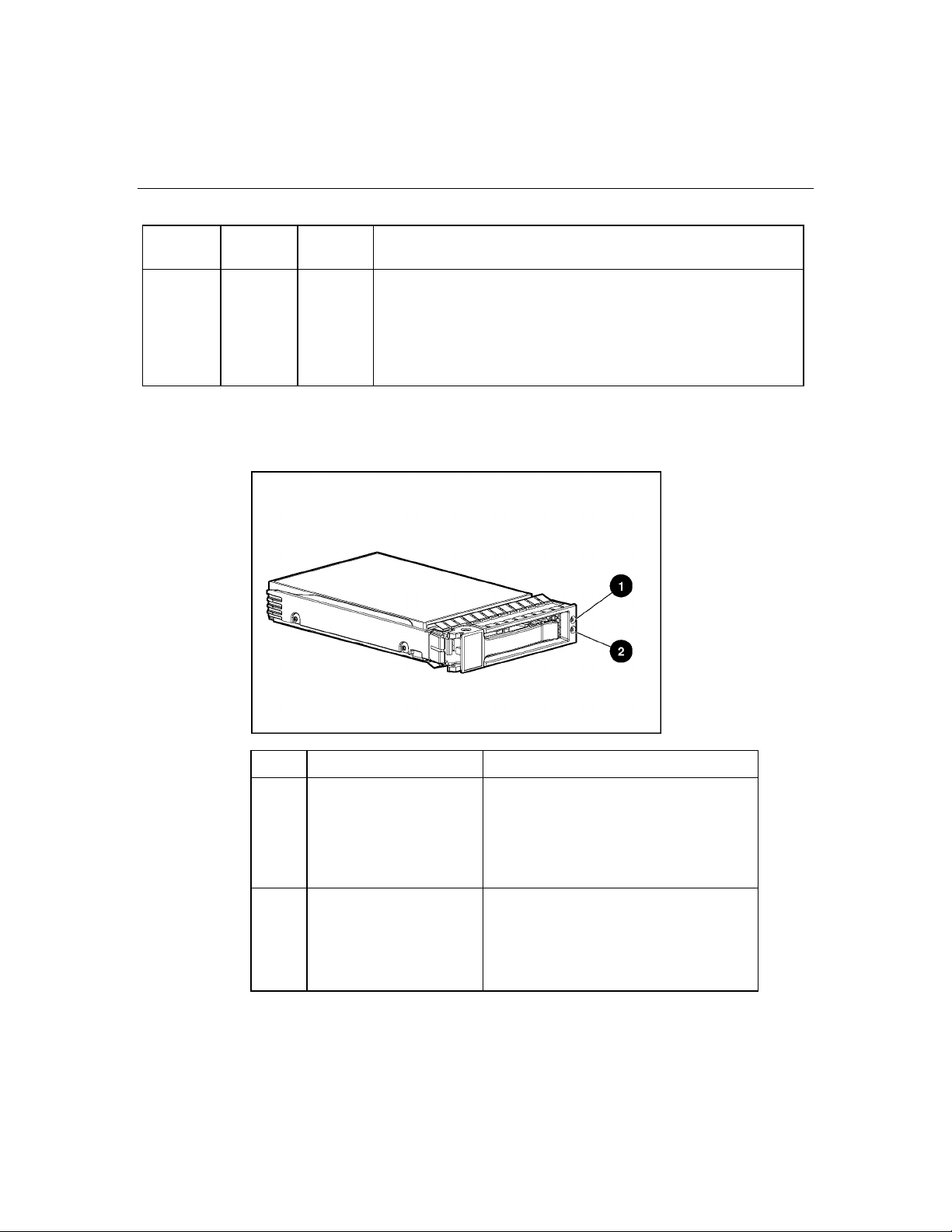
SATA or SAS hard drive LEDs
Item LED Description Status
1 Online/Activity status Green = Drive activity
Flashing green = High activity on the
drive or drive is being configured as part
of an array
Off = No drive activity
2 Fault/UID status Amber = Drive failure
Flashing amber = Fault-process activity
Blue = Unit identification is active
Off = No fault-process activity
Page 25
Server component identification 25
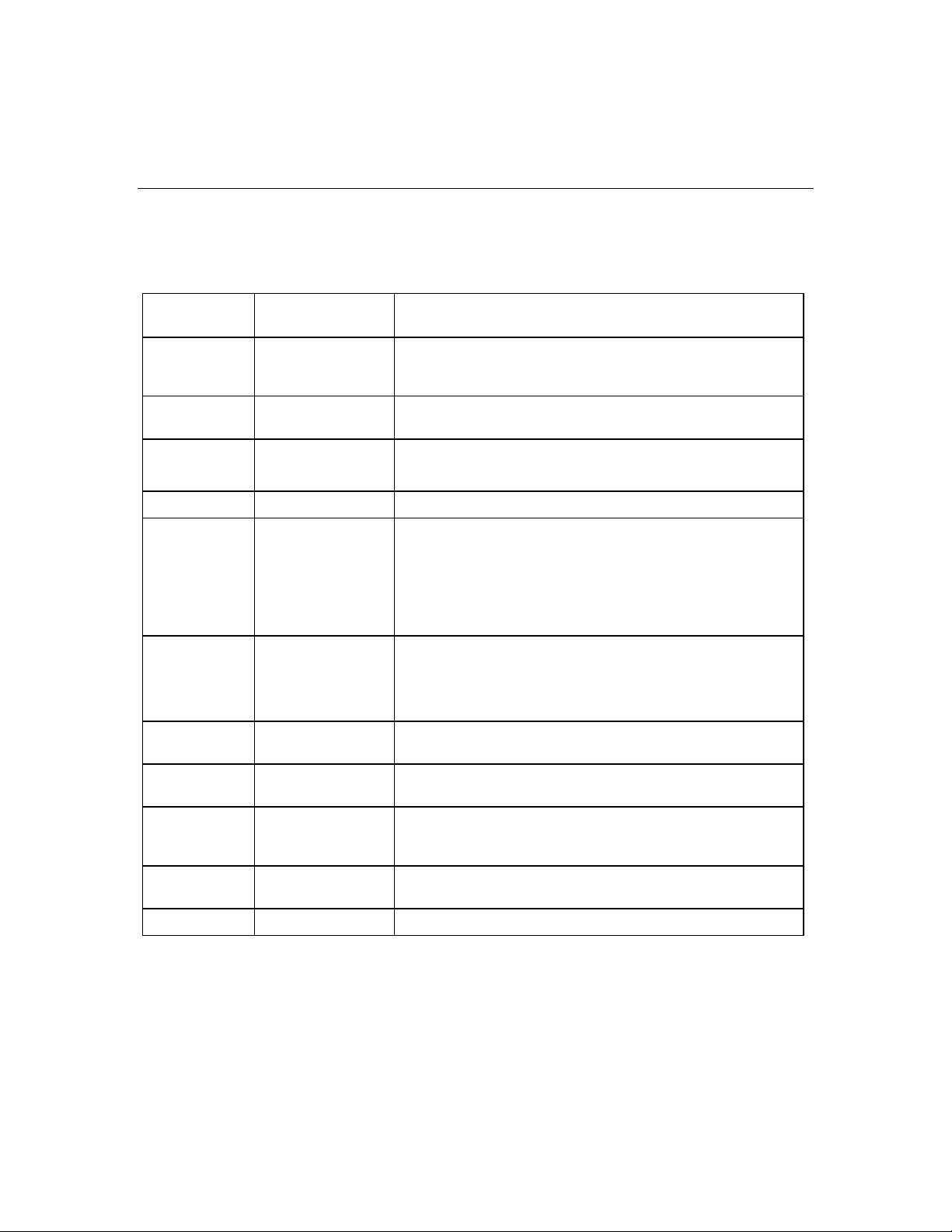
SAS and SATA hard drive LED combinations
Online/Activity
LED (green)
Fault/UID LED
(amber/blue)
Interpretation
On, off, or
flashing
Alternating amber
and blue
The drive has failed, or a predictive failure alert has been
received for this drive; it also has been selected by a
management application.
On, off, or
flashing
On Amber, flashing
Steadily blue The drive is operating normally, and it has been selected by a
management application.
A predictive failure alert has been received for this drive.
regularly (1 Hz)
Replace the drive as soon as possible.
On Off The drive is online, but it is not active currently.
Flashing
regularly (1 Hz)
Amber, flashing
regularly (1 Hz)
Do not remove the drive. Removing a drive may terminate
the current operation and cause data loss.
The drive is part of an array that is undergoing capacity
expansion or stripe migration, but a predictive failure alert has
been received for this drive. To minimize the risk of data loss, do
not replace the drive until the expansion or migration is complete.
Flashing
regularly (1 Hz)
Off
Do not remove the drive. Removing a drive may terminate
the current operation and cause data loss.
The drive is rebuilding, or it is part of an array that is undergoing
capacity expansion or stripe migration.
Flashing
irregularly
Flashing
Amber, flashing
regularly (1 Hz)
The drive is active, but a predictive failure alert has been received
for this drive. Replace the drive as soon as possible.
Off The drive is active, and it is operating normally.
irregularly
Off Steadily amber A critical fault condition has been identified for this drive, and the
controller has placed it offline. Replace the drive as soon as
possible.
Off Amber, flashing
regularly (1 Hz)
A predictive failure alert has been received for this drive. Replace
the drive as soon as possible.
Off Off The drive is offline, a spare, or not configured as part of an array.
Page 26
26 HP ProLiant ML370 Generation 4 Server Reference and Troubleshooting Guide
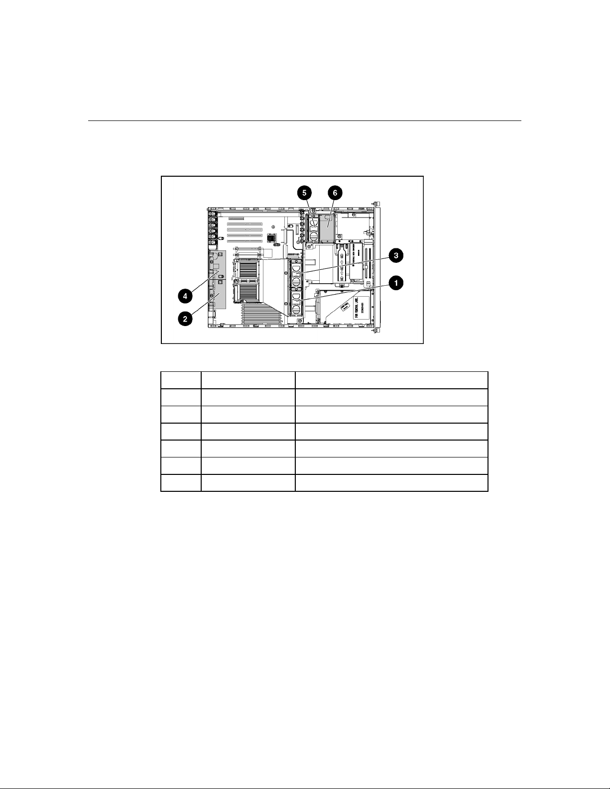
Identifying redundant hot-plug fans
NOTE: Fan locations are located in the chassis.
Item Description Configuration
1 Fan 1 Primary
2 Fan 2 Redundant
3 Fan 3 Primary
4 Fan 4 Redundant
5 Fan 5 Primary
6 Fan 6 Redundant
Fan failures are indicated by amber LEDs located on each hot-plug fan and by
the front panel internal health LED. When a fan failure occurs, the internal health
LED illuminates red in non-redundant mode and amber in redundant mode.
Page 27
27
Server operations
In this section
Powering up the server .................................................................................................................27
Powering down the server ............................................................................................................27
Extending the server from the rack...............................................................................................28
Unlocking the front tower bezel ...................................................................................................29
Removing the access panel...........................................................................................................30
Powering up the server
Powering down the server
To power up the server, press the Power On/Standby button.
WARNING: To reduce the risk of personal injury, electric
shock, or damage to the equipment, remove the power cord to
remove power from the server. The front panel Power On/Standby
button does not completely shut off system power. Portions of the
power supply and some internal circuitry remain active until AC
power is removed.
IMPORTANT: If installing a hot-plug device, it is not necessary to
power down the server.
1. Shut down the OS as directed by the OS documentation.
2. Press the Power On/Standby button to place the server in standby mode.
When the server enters standby power mode, the system power LED changes
to amber.
3. Disconnect the power cords.
The system is now without power.
Page 28
28 HP ProLiant ML370 Generation 4 Server Reference and Troubleshooting Guide
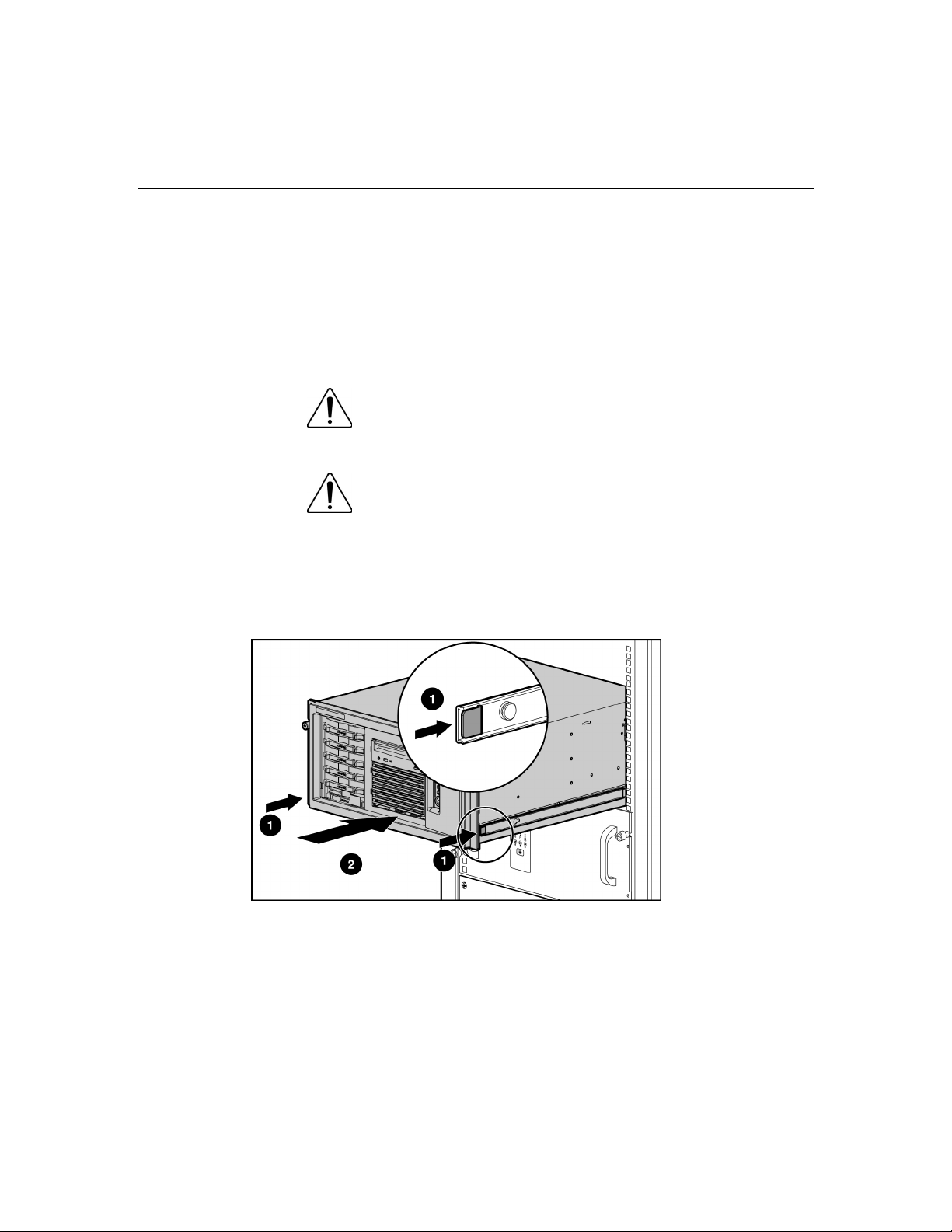
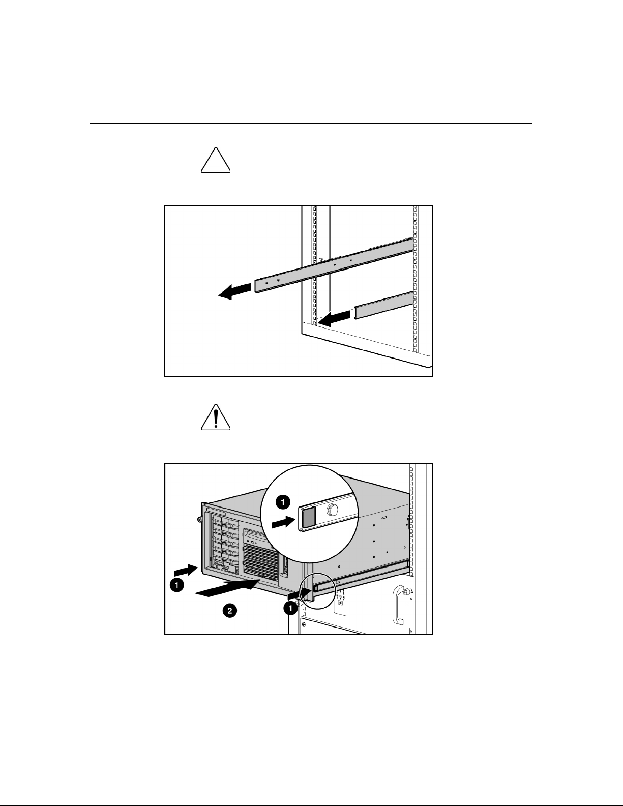
Extending the server from the rack
1. Loosen the thumbscrews that secure the server faceplate to the front of the
rack.
IMPORTANT: If the server is installed in a telco rack, remove the
server from the rack to access internal components.
2. Extend the server on the rack rails until the server rail-release latches engage.
WARNING: To reduce the risk of personal injury or
equipment damage, be sure that the rack is adequately stabilized
before extending a component from the rack.
WARNING: To reduce the risk of personal injury, be
careful when pressing the server rail-release latches and sliding
the server into the rack. The sliding rails could pinch your fingers.
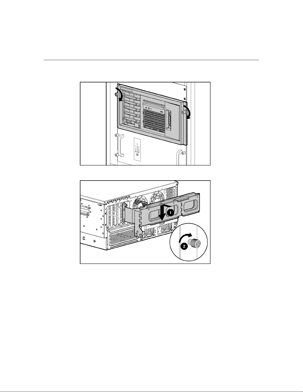
3. After performing the installation or maintenance procedure, slide the server
back into the rack:
a. Press the server rail-release latches and slide the server fully into rack.
b. Secure the server by tightening the thumbscrews.
Page 29
Server operations 29
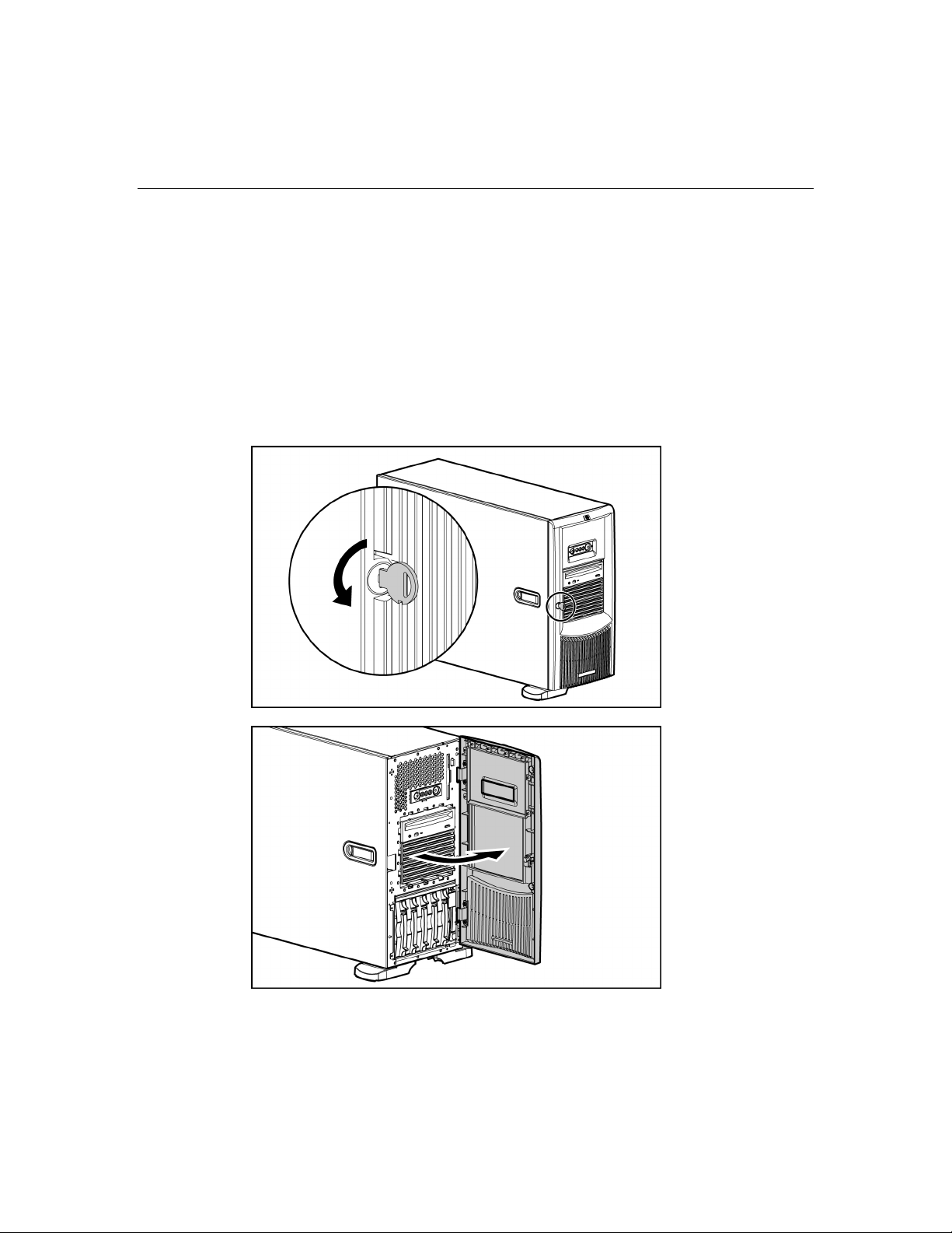
Unlocking the front tower bezel
Tower servers have a removable front bezel that must be unlocked and opened
before accessing the hard drive cage, and before removing the access panel. The
door must remain closed during normal server operations.
Use the key provided with the server to unlock the bezel with a counterclockwise
turn.
If necessary, remove the front bezel.
Page 30
30 HP ProLiant ML370 Generation 4 Server Reference and Troubleshooting Guide
Removing the access panel
WARNING: To reduce the risk of personal injury from hot
surfaces, allow the drives and the internal system components to
cool before touching them.
CAUTION: Do not operate the server for long periods without
the access panel. Operating the server without the access panel results
in improper airflow and improper cooling that can lead to thermal
damage.
1. Power down the server if performing a non-hot-plug installation or
maintenance procedure ("Powering down the server" on page 27
2. Extend or remove the server from the rack ("Extending the server from the
rack" on page 28
).
).
3. Open the front bezel ("Unlocking the front tower bezel" on page 29
).
4. Lift up on the hood latch handle and remove the access panel.
After installing hardware options, replace the access panel. Be sure that the panel
is locked into place securely before powering up the server.
Page 31

31
Server setup
In this section
Optional installation services........................................................................................................31
Rack planning resources...............................................................................................................32
Optimum environment..................................................................................................................33
Rack warnings and cautions .........................................................................................................36
Identifying rack server shipping carton contents..........................................................................39
Identifying tower server shipping carton contents........................................................................39
Installing hardware options ..........................................................................................................40
Setting up a tower server ..............................................................................................................40
Installing the server into the rack .................................................................................................42
Powering up and configuring the server.......................................................................................50
Installing the operating system.....................................................................................................50
Registering the server ...................................................................................................................51
Optional installation services
Delivered by experienced, certified engineers, HP Care Pack services help you
keep your servers up and running with support packages tailored specifically for
HP ProLiant systems. HP Care Packs let you integrate both hardware and
software support into a single package. A number of service level options are
available to meet your needs.
HP Care Pack Services offer upgraded service levels to expand your standard
product warranty with easy-to-buy, easy-to-use support packages that help you
make the most of your server investments. Some of the Care Pack services are:
•
Hardware support
− 6-Hour Call-to-Repair
− 4-Hour 24x7 Same Day
− 4-Hour Same Business Day
•
Software support
Page 32

32 HP ProLiant ML370 Generation 4 Server Reference and Troubleshooting Guide
− Microsoft®
− Linux
− HP ProLiant Essentials (HP SIM and RDP)
− VMWare
• • Integrated hardware and software support
− Critical Service
− Proactive 24
− Support Plus
− Support Plus 24
Startup and implementation services for both hardware and software
For more information on Care Packs, refer to the HP website
(http://www.hp.com/hps/carepack/servers/cp_proliant.html
).
Rack planning resources
The rack resource kit ships with all HP branded or Compaq branded 9000,
10000, and H9 series racks. A summary of the content of each resource follows:
• Custom Builder is a web-based service for configuring one or many racks.
Rack configurations can be created using:
− A simple, guided interface
− Build-it-yourself mode
For more information, refer to the HP website
(http://www.hp.com/products/configurator
).
• The Installing Rack Products video provides a visual overview of operations
required for configuring a rack with rack-mountable components. It also
provides the following important configuration steps:
− Planning the site
− Installing rack servers and rack options
Page 33

Server setup 33
− Cabling servers in a rack
− Coupling multiple racks
• The Rack Products Documentation CD enables you to view, search, and print
documentation for HP and Compaq branded racks and rack options. It also
helps you set up and optimize a rack in a manner that best fits your
environment.
If you intend to deploy and configure multiple servers in a single rack, refer to
the white paper on high-density deployment on the HP website
(http://www.hp.com/products/servers/platforms
).
Optimum environment
When installing the server, select a location that meets the environmental
standards described in this section.
Space and airflow requirements
Tower Server
In a tower configuration, leave at least a 7.6-cm (3-in) clearance space at the
front and back of the server for proper ventilation.
Rack Server
To allow for servicing and adequate airflow, observe the following space and
airflow requirements when deciding where to install a rack:
•
Leave a minimum clearance of 76.2 cm (30 in) in front of the rack.
•
Leave a minimum clearance of 76.2 cm (30 in) behind the rack.
•
Leave a minimum clearance of 121.9 cm (48 in) from the back of the rack to
the back of another rack or row of racks.
HP servers draw in cool air through the front and expel warm air through the
rear. Therefore, the front and rear rack doors must be adequately ventilated to
allow ambient room air to enter, and allow the warm air to escape from the
cabinet.
Page 34

34 HP ProLiant ML370 Generation 4 Server Reference and Troubleshooting Guide
CAUTION: To prevent improper cooling and damage to the
equipment, do not block the ventilation openings.
The 9000 and 10000 Series racks provide proper server cooling from flowthrough perforations in the front and rear doors that provide 64 percent open area
for ventilation.
CAUTION: When using a Compaq branded 7000 Series rack,
you must install the high airflow rack door insert [P/N 327281-B21 (42U)
or P/N 157847-B21 (22U)] to provide proper front-to-back airflow and
cooling.
CAUTION: If a third-party rack is used, observe the following
additional requirements to ensure adequate airflow and to prevent
damage to the equipment:
• • Front and rear doors—If the 42U rack includes closing front and rear
doors, you must allow 5,350 sq cm (830 sq in) of holes evenly
distributed from top to bottom to permit adequate airflow (equivalent
to the required 64 percent open area for ventilation).
Side—The clearance between the installed rack component and the
side panels of the rack must be a minimum of 7 cm (2.75 in).
When vertical space in the rack is not filled by a server or rack component, the
gaps between the components cause changes in airflow through the rack and
across the servers. Cover all gaps with blanking panels to maintain proper
airflow.
CAUTION: Always use blanking panels to fill empty vertical
spaces in the rack. This arrangement ensures proper airflow. Using a
rack without blanking panels results in improper cooling that can lead to
thermal damage.
Temperature requirements
To ensure continued safe and reliable equipment operation, install or position the
system in a well-ventilated, climate-controlled environment.
Page 35

Server setup 35
The maximum recommended ambient operating temperature (TMRA) for most
server products is 35°C (95°F). The temperature in the room where the rack is
located must not exceed 35°C (95°F).
CAUTION: To reduce the risk of damage to the equipment
when installing third-party options:
• • Do not permit optional equipment to impede airflow around the
server or to increase the internal rack temperature beyond the
maximum allowable limits.
Do not exceed the manufacturer’s TMRA.
Power requirements
Installation of this equipment must comply with local and regional electrical
regulations governing the installation of information technology equipment by
licensed electricians. This equipment is designed to operate in installations
covered by NFPA 70, 1999 Edition (National Electric Code) and NFPA-75, 1992
(code for Protection of Electronic Computer/Data Processing Equipment). For
electrical power ratings on options, refer to the product rating label or the user
documentation supplied with that option.
WARNING: To reduce the risk of personal injury, fire, or
damage to the equipment, do not overload the AC supply branch
circuit that provides power to the rack. Consult the electrical
authority having jurisdiction over wiring and installation
requirements of your facility.
CAUTION: Protect the server from power fluctuations and
temporary interruptions with a regulating uninterruptible power supply
(UPS). This device protects the hardware from damage caused by
power surges and voltage spikes and keeps the system in operation
during a power failure.
When installing more than one server, you may need to use additional power
distribution devices to safely provide power to all devices. Observe the following
guidelines:
• Balance the server power load between available AC supply branch circuits.
Page 36

36 HP ProLiant ML370 Generation 4 Server Reference and Troubleshooting Guide
•
Do not allow the overall system AC current load to exceed 80 percent of the
branch circuit AC current rating.
•
Do not use common power outlet strips for this equipment.
•
Provide a separate electrical circuit for the server.
Electrical grounding requirements
The server must be grounded properly for proper operation and safety. In the
United States, you must install the equipment in accordance with NFPA 70, 1999
Edition (National Electric Code), Article 250, as well as any local and regional
building codes. In Canada, you must install the equipment in accordance with
Canadian Standards Association, CSA C22.1, Canadian Electrical Code. In all
other countries, you must install the equipment in accordance with any regional
or national electrical wiring codes, such as the International Electrotechnical
Commission (IEC) Code 364, parts 1 through 7. Furthermore, you must be sure
that all power distribution devices used in the installation, such as branch wiring
and receptacles, are listed or certified grounding-type devices.
Because of the high ground-leakage currents associated with multiple servers
connected to the same power source, HP recommends the use of a PDU that is
either permanently wired to the building’s branch circuit or includes a
nondetachable cord that is wired to an industrial-style plug. NEMA locking-style
plugs or those complying with IEC 60309 are considered suitable for this
purpose. Using common power outlet strips for the server is not recommended.
Rack warnings and cautions
WARNING: To reduce the risk of personal injury or
damage to the equipment, be sure that:
Page 37

Server setup 37
The leveling jacks are extended to the floor. •
•
The full weight of the rack rests on the leveling jacks.
•
The stabilizing feet are attached to the rack if it is a single-rack
installation.
•
The racks are coupled together in multiple-rack installations.
•
Only one component is extended at a time. A rack may become
unstable if more than one component is extended for any
reason.
WARNING: To reduce the risk of personal injury or
equipment damage when unloading a rack:
At least two people are needed to safely unload the rack from
•
the pallet. An empty 42U rack can weigh as much as 115 kg
(253 lb), can stand more than 2.1 m (7 ft) tall, and may become
unstable when being moved on its casters.
• Never stand in front of the rack when it is rolling down the ramp
from the pallet. Always handle the rack from both sides.
WARNING: When installing a server in a telco rack, be
sure that the rack frame is adequately secured to the top and
bottom of the building structure.
WARNING: This server is very heavy. To reduce the risk
of personal injury or damage to the equipment:
Page 38

38 HP ProLiant ML370 Generation 4 Server Reference and Troubleshooting Guide
Observe local occupational health and safety requirements and
•
guidelines for manual material handling.
• • Get help to lift and stabilize the product during installation or
removal, especially when the product is not fastened to the
rails. When the server weighs more than 22.5 kg (50 lb), at least
two people must lift the server into the rack together. If the
server is loaded into the rack above chest level, a third person
must assist in aligning the rails while the other two support the
server.
Use caution when installing the server in or removing the
server from the rack; it is unstable when not fastened to the
rails.
WARNING: To reduce the risk of personal injury from hot
surfaces, allow the drives and the internal system components to
cool before touching them.
WARNING: To reduce the risk of personal injury, electric
shock, or damage to the equipment, remove the power cord to
remove power from the server. The front panel Power On/Standby
button does not completely shut off system power. Portions of the
power supply and some internal circuitry remain active until AC
power is removed.
CAUTION: Protect the server from power fluctuations and
temporary interruptions with a regulating uninterruptible power supply
(UPS). This device protects the hardware from damage caused by
power surges and voltage spikes and keeps the system in operation
during a power failure.
CAUTION: Do not operate the server for long periods without
the access panel. Operating the server without the access panel results
in improper airflow and improper cooling that can lead to thermal
damage.
Page 39

Server setup 39
Identifying rack server shipping carton contents
Unpack the server shipping carton and locate the materials and documentation
necessary for installing the server. All the rack mounting hardware necessary for
installing the server into the rack is included with the rack or the server.
The contents of the server shipping carton include:
•
Server
•
Power cord
•
Hardware documentation, Documentation CD, and software products
•
Rack mounting hardware
In addition to the supplied items, you may need:
•
Hardware options
•
Operating system or application software
•
PDU
Identifying tower server shipping carton contents
Unpack the server shipping carton and locate the materials and documentation
necessary for installing the server.
The contents of the server shipping carton include:
•
Server
•
Power cord
•
Keyboard
•
Mouse
•
Hardware documentation, Documentation CD, and software products
In addition to the supplied items, you may need:
•
Hardware options
Page 40

40 HP ProLiant ML370 Generation 4 Server Reference and Troubleshooting Guide
• • Operating system or application software
PDU
Installing hardware options
Install any hardware options before initializing the server. For options installation
information, refer to the option documentation. For server-specific information,
refer to "Hardware options installation (on page 53
)."
Setting up a tower server
Follow the steps in this section to set up a tower model server. If you are going to
install the server into a rack, refer to the rack installation ("Installing the server
into the rack" on page 42
1. Connect peripheral devices to the server.
WARNING: To reduce the risk of electric shock, fire, or
damage to the equipment, do not plug telephone or
telecommunications connectors into RJ-45 connectors.
) section.
Page 41

Server setup 41
IMPORTANT: If the RILOE II board is installed in the server, be sure
that you attach the video cable to the video connector on the rear of the
RILOE II board. The standard video connector on the server rear panel
is not used when the RILOE II board is installed. For more information,
refer to the HP Remote Insight Lights-Out Edition II User Guide.
Item Description Item Description
1 x4 PCI Express expansion slots 9 Auxillary VHDCI SCSI blank
2 100-MHz PCI-X expansion slots 10 Mouse connector
3 Unit ID LED 11 Keyboard connector
4 Ethernet 10/100/1000 port 12 Serial connector B
5 iLO management port 13 Serial connector A
6 Parallel connector 14 USB connectors
7 Video connector 15 Primary hot-plug power supply
8 T-15 Torx screwdriver 16 Redundant hot-plug power supply
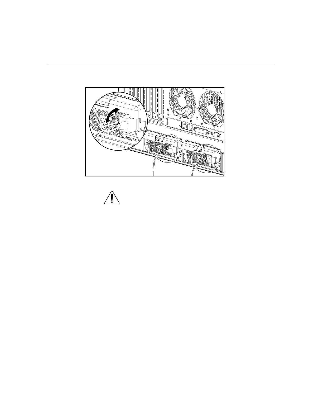
2. Connect the power cord to the back of the server.
3. Open the power cord retaining clip, and thread the power cord through the
retaining clip.
Page 42
42 HP ProLiant ML370 Generation 4 Server Reference and Troubleshooting Guide
4. Snap the tab into place to secure the power cord.
5. Connect the power cord to the AC power source.
WARNING: To reduce the risk of electric shock or damage
to the equipment:
Do not disable the power cord grounding plug. The grounding
•
plug is an important safety feature.
• • Plug the power cord into a grounded (earthed) electrical outlet
that is easily accessible at all times.
Unplug the power cord from the power supply to disconnect
power to the equipment.
Do not route the power cord where it can be walked on or pinched
by items placed against it. Pay particular attention to the plug,
electrical outlet, and the point where the cord extends from the
server.
Installing the server into the rack
Follow the steps in this section if you are installing the server into a rack with
square holes. If you are installing the server into a rack with round holes, order
the appropriate rack installation option kit, and then refer to the installation
instructions that ship with the option kit for more information.
Page 43
Server setup 43
NOTE: The steps in this section work with most third-party racks with
square holes. If they do not work with the rack you are using, order the
option kit for racks with round holes.
If you are installing the server into a telco rack, order the appropriate option kit at
the RackSolutions.com website (http://www.racksolutions.com/hp
). Follow the
server-specific instructions on the website to install the rack brackets. After
installing the brackets, follow the steps in this section.
WARNING: When installing a server in a telco rack, be
sure that the rack frame is adequately secured to the top and
bottom of the building structure.
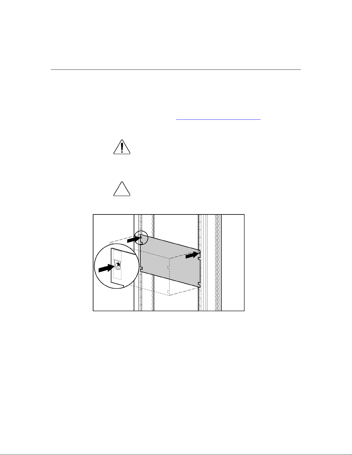
1. Mark the rack.
CAUTION: Always plan the rack installation so that the
heaviest item is on the bottom of the rack. Install the heaviest item first,
and continue to populate the rack from the bottom to the top.
NOTE: Rack components are removed for clarity.
Page 44

44 HP ProLiant ML370 Generation 4 Server Reference and Troubleshooting Guide
2. Attach cage nuts to the rack.
NOTE: Round-hole cage nuts will function the same as the square-hole
cage nuts shown.
3. Secure each server rail to the server.
Page 45
Server setup 45
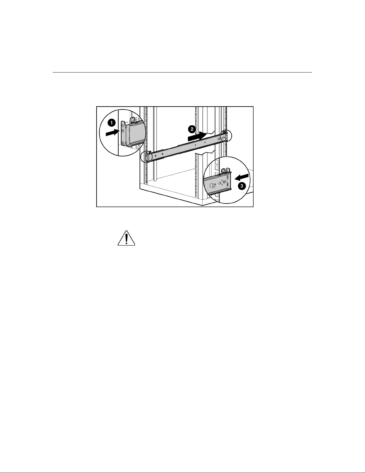
4. Secure the left and right standard rack rails to the appropriate side of the
rack.
5. Extend the slides from the standard rack rails, and then slide the server rails
into the slides.
WARNING: To reduce the risk of personal injury or
equipment damage, be sure that the rack is adequately stabilized
before sliding the server rails into the rack rails.
Page 46
46 HP ProLiant ML370 Generation 4 Server Reference and Troubleshooting Guide
CAUTION: Be sure to keep the server parallel to the floor
when sliding the server rails into the rack rails. Tilting the server up or
down could result in damage to the rails.
6. Press the rail-release latches and slide the server into the rack.
WARNING: To reduce the risk of personal injury, be
careful when pressing the server rail-release latches and sliding
the server into the rack. The sliding rails could pinch your fingers.
Page 47
Server setup 47
7. Secure the server to the rack.
8. Secure the cable management arm bracket to the server.
Page 48

48 HP ProLiant ML370 Generation 4 Server Reference and Troubleshooting Guide
9. Secure the cable management arm to the slide rail.
10. Connect peripheral devices to the server. Refer to "Rear Panel Components
(on page 12
damage to the equipment, do not plug telephone or
telecommunications connectors into RJ-45 connectors.
IMPORTANT: If the RILOE II board is installed in the server, be sure
that you attach the video cable to the video connector on the rear of the
RILOE II board. The standard video connector on the server rear panel
is not used when the RILOE II board is installed. For more information,
refer to the HP Remote Insight Lights-Out Edition II User Guide.
IMPORTANT: When using cable management arm components, be
sure to leave enough slack in each of the cables to prevent damage to
the cables when the server is extended from the rack.
)."
WARNING: To reduce the risk of electric shock, fire, or
11. Connect the power cord to the back of the server.
12. Open the power cord retaining clip, and thread the power cord through the
retaining clip.
Page 49

Server setup 49
13. Snap the tab into place to secure the power cord.
14. Secure cables to the cable management arm.
IMPORTANT: When using cable management arm components, be
sure to leave enough slack in each of the cables to prevent damage to
the cables when the server is extended from the rack.
15. Connect the power cord to the AC power source.
WARNING: To reduce the risk of electric shock or damage
to the equipment:
Page 50

50 HP ProLiant ML370 Generation 4 Server Reference and Troubleshooting Guide
Do not disable the power cord grounding plug. The grounding
•
plug is an important safety feature.
•
Plug the power cord into a grounded (earthed) electrical outlet
that is easily accessible at all times.
•
Unplug the power cord from the power supply to disconnect
power to the equipment.
•
Do not route the power cord where it can be walked on or
pinched by items placed against it. Pay particular attention to
the plug, electrical outlet, and the point where the cord extends
from the server.
Powering up and configuring the server
To power up the server, press the Power On/Standby button.
While the server boots, RBSU and the ORCA utility are automatically
configured to prepare the server for operating system installation.
To configure these utilities manually:
•
Press the F8 key when prompted during the array controller initialization to
configure the array controller using ORCA.
•
Press the F9 key when prompted during the boot process to change the server
settings using RBSU. The system is set up by default for the English
language.
For more information on the automatic configuration, refer to the HP ROM-
Based Setup Utility User Guide located on the Documentation CD.
Installing the operating system
To operate properly, the server must have a supported operating system. For the
latest information on supported operating systems, refer to the HP website
(http://www.hp.com/go/supportos
Two methods are available to install an operating system on the server:
).
Page 51

Server setup 51
• • SmartStart assisted installation—Insert the SmartStart CD into the CD-ROM
drive and reboot the server.
Manual installation—Insert the operating system CD into the CD-ROM drive
and reboot the server. This process may require you to obtain additional
drivers from the HP website (http://www.hp.com/support
).
Follow the on-screen instructions to begin the installation process.
For information on using these installation paths, refer to the SmartStart
installation poster in the HP ProLiant Essentials Foundation Pack, included with
the server.
Registering the server
To register a server, refer to the registration card in the HP ProLiant Essentials
Foundation Pack or the HP Registration website (http://register.hp.com
).
Page 52

Page 53
53
Hardware options installation
In this section
Introduction ..................................................................................................................................53
Processor options..........................................................................................................................54
Memory options............................................................................................................................58
Hot-plug SCSI hard drive options ................................................................................................60
SAS-SATA hard drive cage .........................................................................................................62
Removable media devices ............................................................................................................67
Redundant hot-plug fans...............................................................................................................75
Redundant hot-plug power supply................................................................................................80
Expansion boards..........................................................................................................................82
Remote Insight Lights-Out Edition II board.................................................................................86
VHDCI or HD68 SCSI cable option ............................................................................................87
Duplex SCSI board option............................................................................................................89
Tower-to-rack conversion option .................................................................................................90
Introduction
If more than one option is being installed, read the installation instructions for all
the hardware options and identify similar steps to streamline the installation
process.
WARNING: To reduce the risk of personal injury from hot
surfaces, allow the drives and the internal system components to
cool before touching them.
CAUTION: To prevent damage to electrical components,
properly ground the server before beginning any installation procedure.
Improper grounding can cause electrostatic discharge.
Page 54

54 HP ProLiant ML370 Generation 4 Server Reference and Troubleshooting Guide
Processor options
The server supports single- and dual-processor operation. With two processors
installed, the server supports boot functions through the processor installed in
processor socket 1. However, if processor 1 fails, the system attempts to boot
from processor 2 and provides a processor failure message.
The server uses PPMs as DC-to-DC converters to provide the proper power to
each processor. Each PPM must be installed in the slot adjacent to its processor.
CAUTION: To prevent thermal instability and damage to the
server, do not separate the processor from the heatsink. The processor,
heatsink, and retaining clip make up a single assembly.
CAUTION: To prevent possible server malfunction and
damage to the equipment, do not mix processors of different types.
IMPORTANT: If upgrading processor speed, update the system ROM
before installing the processor.
IMPORTANT: Processor socket 1 and PPM slot 1 must be populated
at all times or the server will not function properly.
IMPORTANT: Always install a PPM when you install a processor. The
system fails to boot if the PPM is missing.
IMPORTANT: To ensure proper cooling, be sure the processor baffle is
installed at all times.
To install a processor:
1. Power down the server ("Powering down the server" on page 27
).
2. Extend or remove the server from the rack ("Extending the server from the
rack" on page 28
).
3. Remove the front bezel door, if necessary.
4. Remove the access panel ("Removing the access panel" on page 30
).
Page 55

Hardware options installation 55
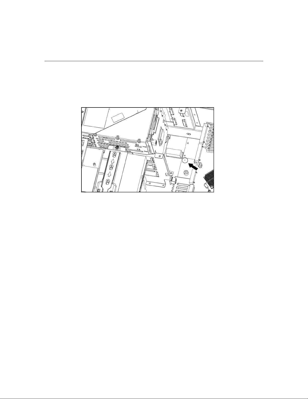
5. Remove the processor air baffle using the two thumbscrews.
6. Open the processor retaining bracket.
7. Release the processor locking lever.
Page 56

56 HP ProLiant ML370 Generation 4 Server Reference and Troubleshooting Guide
CAUTION: Failure to open the processor locking lever
completely prevents the processor from seating during installation,
leading to hardware damage.
8. Install the processor.
CAUTION: To prevent possible server malfunction or damage
to the equipment, be sure to completely close the processor locking
lever.
Page 57

Hardware options installation 57
9. Close the processor retaining bracket.
10. Open the latches on the corresponding PPM slot.
11. Install the PPM.
IMPORTANT: Always install a PPM when you install a processor. The
system fails to boot if the corresponding PPM is missing.
NOTE: The appearance of compatible PPMs may vary.
12. Reinstall the processor air baffle.
13. Install the access panel.
Page 58

58 HP ProLiant ML370 Generation 4 Server Reference and Troubleshooting Guide
Memory options
You can expand server memory by installing PC2-3200R Registered DDRII
DRAM DIMMs. The system supports up to eight DIMMs.
The server supports two types of memory configurations:
• • Standard memory configuration (Advanced ECC) for maximum
performance, using up to 16 GB of active memory (eight 2-GB memory
modules)
Online spare memory configuration for maximum availability, using up to 12
GB of active memory and 4 GB of online spare memory
Refer to "DIMM Slots (on page 17
)" for DIMM slot locations and bank
assignments.
Online spare memory configuration
In the online spare configuration, the ROM automatically configures the last
populated bank as the spare memory. If only banks A and B are populated,
bank B is the spare bank. If banks A, B, C, and D are populated, bank D is the
spare bank. If DIMMs in a non-spare bank exceed the limit for the single-bit
correctable errors threshold as defined by the Pre-Failure Warranty, the system
copies the memory contents of the failing bank to the spare bank. The system
then deactivates the failing bank and automatically switches over to the spare
bank.
For online spare memory support, DIMMs installed in the spare bank must be of
equal or greater capacity than the DIMMs installed in other banks.
For example, if bank A is populated with two 512-MB DIMMs and bank B is
populated with two 1-GB DIMMs, bank C must be populated with two 1-GB or
greater DIMMs in order for online spare memory support to function properly.
After installing DIMMs, use RBSU to configure the system for online spare
memory support ("Configuring online spare memory" on page 114
).
Page 59

Hardware options installation 59
DIMM installation guidelines
You must observe the following guidelines when installing additional memory:
•
Always install memory in pairs of equal capacity.
•
Install only PC2-3200R DIMMs.
•
Install DIMMs into both slots within a single bank.
•
Upgrade memory by installing DIMM pairs into banks in sequential bank
order, starting with bank B.
For online spare memory support, you must also observe additional guidelines
("Online spare memory configuration" on page 58
).
Installing DIMMs
1. Power down the server ("Powering down the server" on page 27).
2. Extend or remove the server from the rack ("Extending the server from the
rack" on page 28
).
3. Remove the front bezel door, if necessary.
4. Remove the access panel ("Removing the access panel" on page 30
).
5. Open the DIMM slot latches.
Page 60
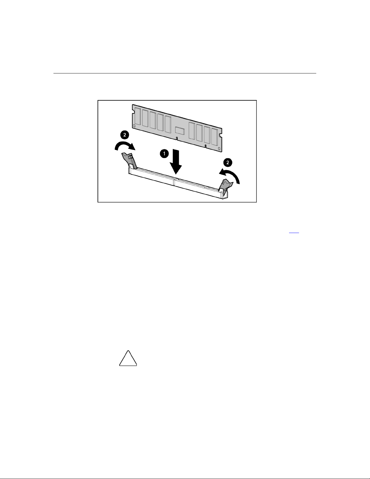
60 HP ProLiant ML370 Generation 4 Server Reference and Troubleshooting Guide
6. Install the DIMM.
7. Install the access panel.
8. If you are installing DIMMs in an online spare configuration, use RBSU to
configure this feature ("Configuring online spare memory" on page 114
).
Hot-plug SCSI hard drive options
When adding SCSI hard drives to the server, observe the following general
guidelines:
• • Hot-plug hard drives must be Ultra320 SCSI drives for optimum
performance. Mixing these types with other drive standards degrades the
overall performance of the drive subsystem.
Drives must be the same capacity to provide the greatest storage space
efficiency when drives are grouped together into the same drive array.
Removing a hot-plug SCSI hard drive
CAUTION: To prevent improper cooling and thermal damage,
do not operate the server unless all bays are populated with either a
component or a blank.
Page 61
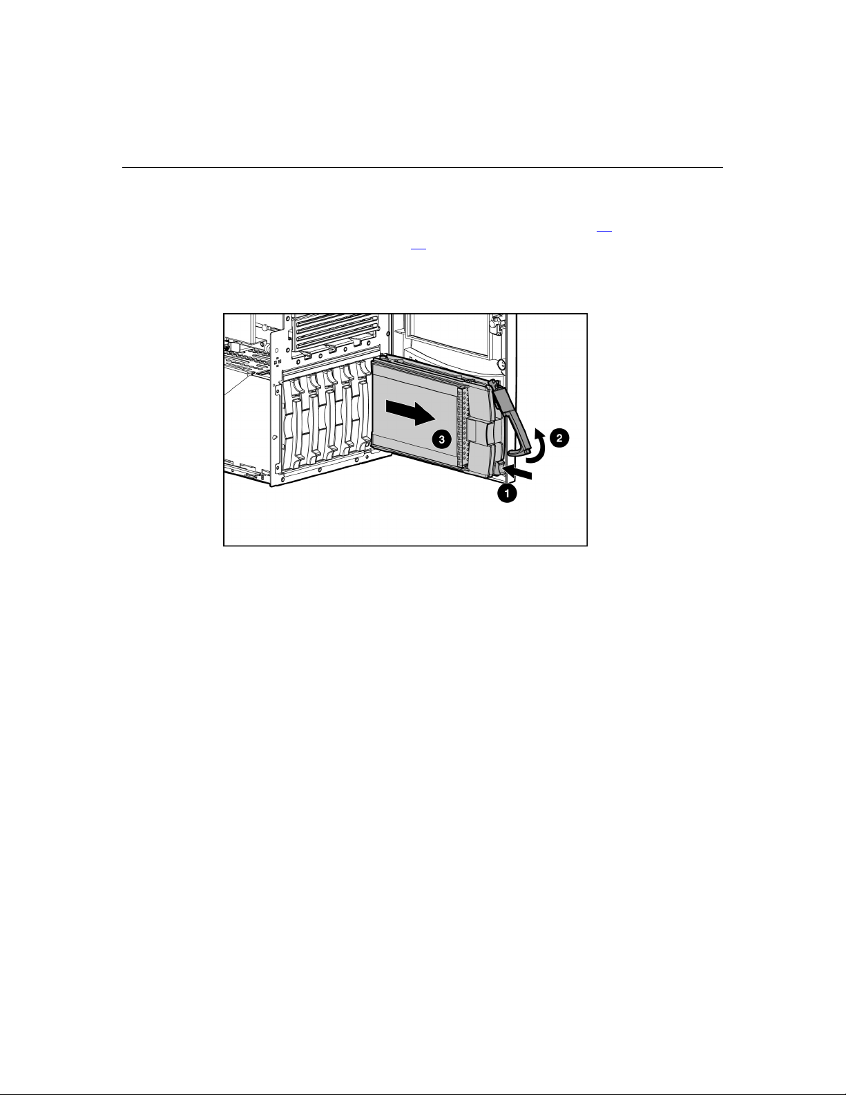
Hardware options installation 61
1. Determine the status of the hard drive from the hot-plug hard drive LEDs
("Hot-plug SCSI hard drive LED combinations" on page 23
hard drive LEDs" on page 22
).
, "Hot-plug SCSI
2. Back up all server data on the hard drive.
3. Remove the hard drive.
Installing a hot-plug SCSI hard drive
1. Remove the existing hard drive blank or hard drive from the drive bay.
Page 62
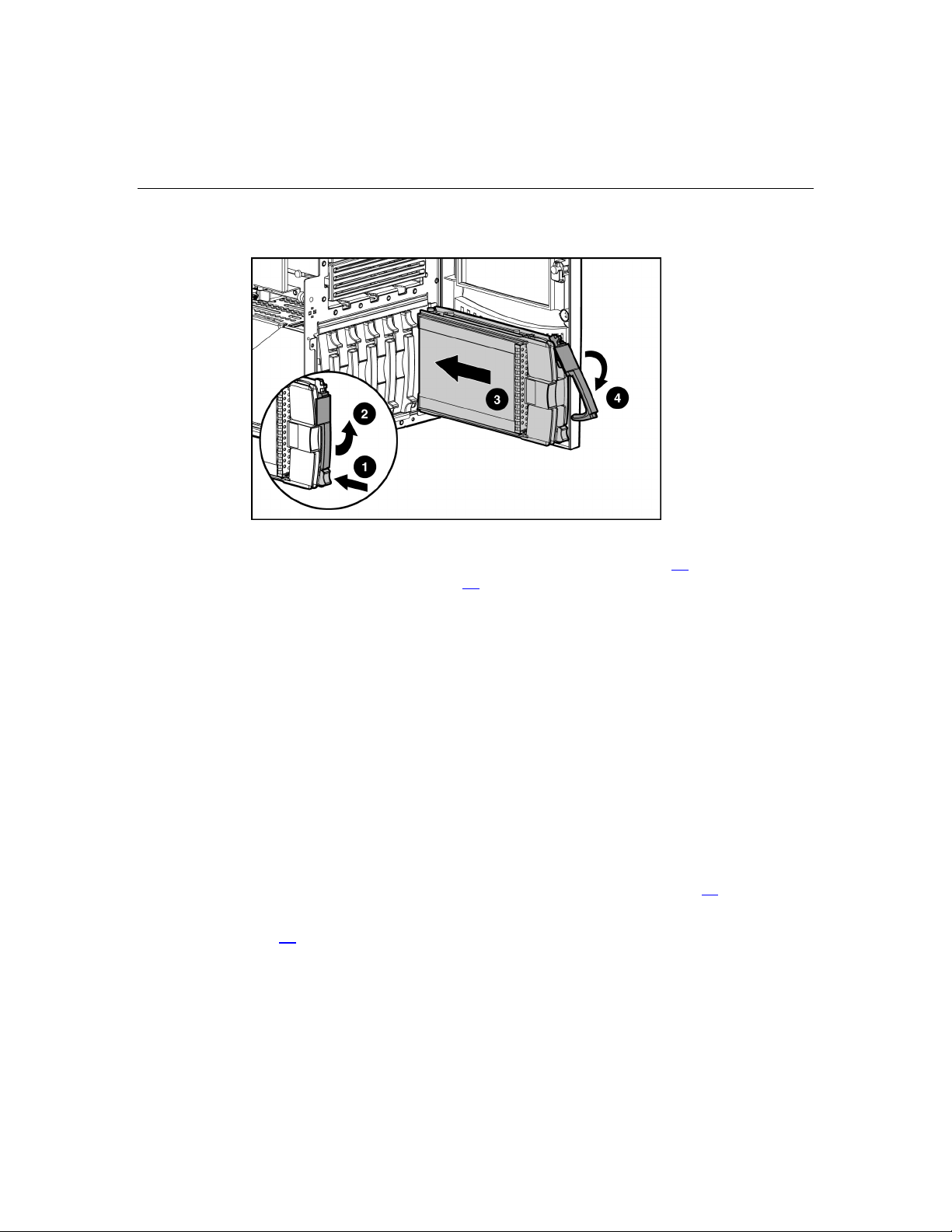
62 HP ProLiant ML370 Generation 4 Server Reference and Troubleshooting Guide
2. Install the hard drive.
3. Determine the status of the hard drive from the hot-plug hard drive LEDs
("Hot-plug SCSI hard drive LED combinations" on page 23
hard drive LEDs" on page 22
4. Resume normal server operations.
).
, "Hot-plug SCSI
SAS-SATA hard drive cage
You can install an eight-bay, hot-plug SAS-SATA drive cage in the HP ProLiant
ML370 Generation 4 Server (tower and rack models). A combination of up to
eight SAS and SATA hard drives can be installed in the drive cage.
Removing the hard drive cage
Before you install the SAS-SATA hard drive cage, you must first remove the
hard drive cage already installed.
1. Power down the server ("Powering down the server" on page 27
2. Unlock and open the front bezel ("Unlocking the front tower bezel" on page
) (tower servers only).
29
3. Remove the rack bezel (rack servers only).
).
Page 63
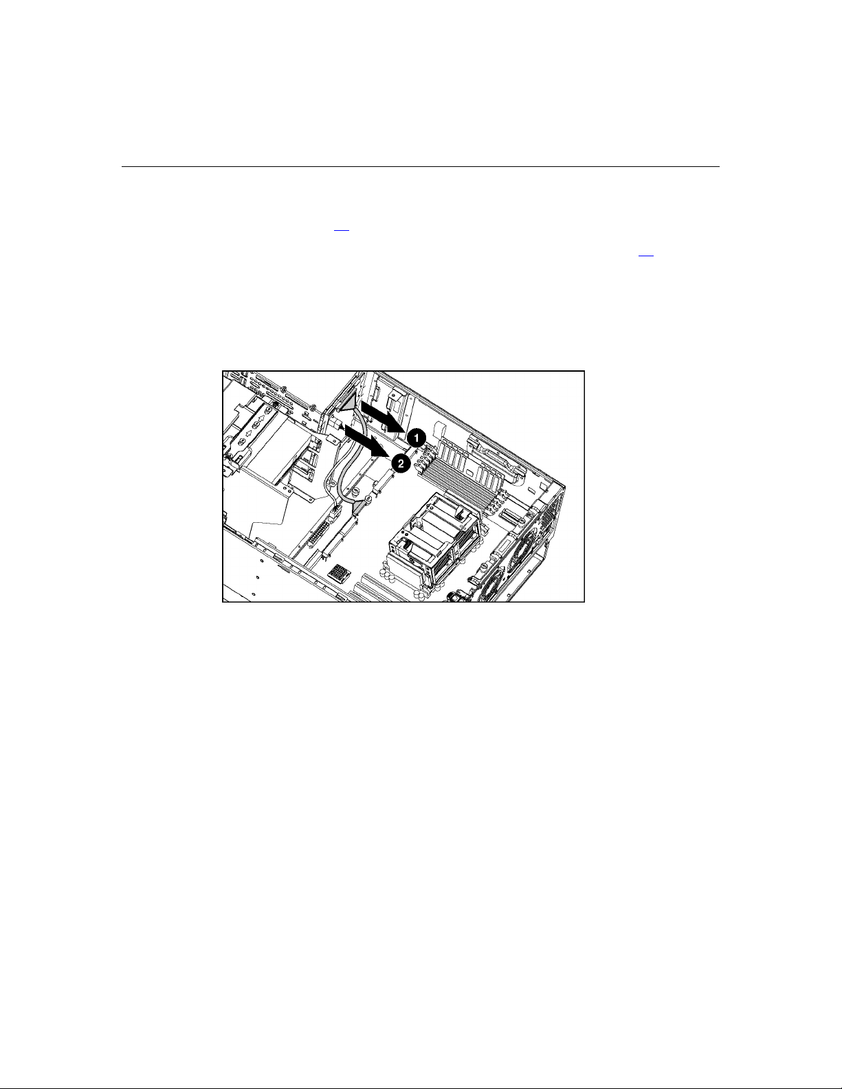
Hardware options installation 63
4. Extend or remove the server from the rack ("Extending the server from the
rack" on page 28
).
5. Remove the access panel ("Removing the access panel" on page 30
).
6. Remove all hard drive blanks.
7. Remove all hot-plug SCSI hard drives.
8. Disconnect the SCSI cables from the SCSI hard drive backplane.
9. Disconnect the power cable from the SCSI hard drive backplane.
10. Remove the four screws that secure the hard drive cage to the chassis.
Page 64

64 HP ProLiant ML370 Generation 4 Server Reference and Troubleshooting Guide
11. Remove the hard drive cage.
Installing the SAS-SATA hard drive cage
1. Install the SAS controller into an empty PCI-X slot.
2. Connect the two SAS-SATA cables to the SAS controller.
3. Slide the drive cage part of the way into the bay.
4. Connect the power cable connectors as follows:
− Connect the 10-pin connector to the SAS-SATA drive cage backplane.
Page 65

Hardware options installation 65
− Connect the 8-pin connector to the 8-pin power cable previously
disconnected from the SCSI drive cage.
− Connect the 4-pin connector to an unused 4-pin media bay power
connector.
NOTE: The center wall is removed for illustration purposes only.
5. Route the SAS-SATA cables through the center wall and connect them to the
drive cage backplane.
6. Slide the drive cage fully into the bay and insert the four screws to secure the
drive cage to the chassis.
Page 66

66 HP ProLiant ML370 Generation 4 Server Reference and Troubleshooting Guide
7. Place the label on the chassis to the right of the drive cage.
8. Remove the desired number of drive blanks.
Page 67

Hardware options installation 67
9. Install SAS or SATA hard drives into the desired bays of the drive cage.
10. Determine the status of each drive by observing the drive LEDs ("SATA or
SAS hard drive LEDs" on page 24
CAUTION: To prevent improper cooling and thermal damage,
do not operate the server unless all bays are populated with either a
component or a blank.
).
The installation is complete.
Removable media devices
Accessing the Removable Media Cage (on page 68)
Half-Height or Full-Height Media Devices ("Installing a half-height or fullheight media device" on page 70
Internal Two-Bay Hot-Plug SCSI Drive Cage ("Installing an optional internal
two-bay hot-plug SCSI drive cage" on page 73
)
)
Page 68

68 HP ProLiant ML370 Generation 4 Server Reference and Troubleshooting Guide
Accessing the removable media cage
The server supports installation of an optional SCSI tape backup drive, internal
two-bay hot-plug SCSI drive cage, or other devices in the removable media area.
IMPORTANT: HP and Compaq branded SCSI non-hot-plug cables are
terminated. Remove all terminating jumpers from third-party SCSI
devices before installing them in the server.
1. Power down the server ("Powering down the server" on page 27).
2. Extend or remove the server from the rack ("Extending the server from the
rack" on page 28
3. Remove the front bezel door, if necessary.
).
4. Remove the access panel ("Removing the access panel" on page 30
CAUTION: Always populate each media bay with either a
device or a blank. Proper airflow can only be maintained when the bays
are populated. Unpopulated drive bays can lead to improper cooling and
thermal damage.
NOTE: HP recommends that you move the CD-ROM drive out of the
media cabling area for ease of installation. It is not necessary to
disconnect and remove the CD-ROM drive from the server entirely.
).
5. Press and hold the sliding media latch to release the bezel blanks, while
pushing the blanks from behind to remove.
Page 69

Hardware options installation 69
NOTE: HP recommends that you remove all bezel blanks to facilitate
drive installation.
6. Store the blanks for later use.
7. Remove all expansion boards.
8. Remove the center wall:
a. Loosen the four thumbscrews, and lift the wall to access the fan cable.
b. Disconnect the fan cable.
c. Lift the center wall fully out of the chassis.
Page 70

70 HP ProLiant ML370 Generation 4 Server Reference and Troubleshooting Guide
9. Install the removable media device. ("Installing a half-height or full-height
media device" on page 70
)
10. When removable media device installation is complete, reinstall the
following items:
− CD-Rom drive, if needed
− Center wall
− Expansion boards
− Processor air baffle
− Bezel blanks
NOTE: If the second media bay is populated with an optional drive,
store the extra bezel blank for later use.
11. Install other hardware options as needed or reinstall the access panel.
12. Power up the server ("Powering up the server" on page 27
Installing a half-height or full-height media device
You can install up to two half-height or one full-height removable media devices
in the removable media cage. To install a half-height or full-height media device:
1. Power down the server ("Powering down the server" on page 27
2. Extend or remove the server from the rack ("Extending the server from the
rack" on page 28
3. Remove the front bezel door, if necessary.
4. Remove the access panel ("Removing the access panel" on page 30
5. Access the removable media cage. ("Accessing the removable media cage"
on page 68
NOTE: HP recommends that you remove all bezel blanks to facilitate
drive installation.
).
)
).
).
).
Page 71

Hardware options installation 71
6. Using the T-15 Torx screwdriver attached to the back of the server, remove
the screws from the bezel blank and attach them to the tape drive or device.
IMPORTANT: Each SCSI device in the server must have a unique
address. The server automatically sets all SCSI IDs for hot-plug drives,
but you must set the SCSI IDs for devices installed in the media cage.
Page 72

72 HP ProLiant ML370 Generation 4 Server Reference and Troubleshooting Guide
7. Slide the device part of the way into the bay.
8. Connect the four-pin power cable to the half-height or full-height drive.
Page 73

Hardware options installation 73
9. Connect the SCSI cable that comes with the device to the SCSI device and
SCSI port 1 or 2 on the system board, or to an HBA installed in an expansion
slot.
10. Slide the media drive fully into the bay until it is seated securely.
Installing an optional internal two-bay hot-plug SCSI drive cage
To install the optional two-bay hot-plug SCSI drive cage:
1. Power down the server ("Powering down the server" on page 27
2. Extend or remove the server from the rack ("Extending the server from the
rack" on page 28
).
3. Remove the front bezel door, if necessary.
4. Remove the access panel ("Removing the access panel" on page 30
5. Access the removable media cage. ("Accessing the removable media cage"
on page 68
)
).
).
Page 74
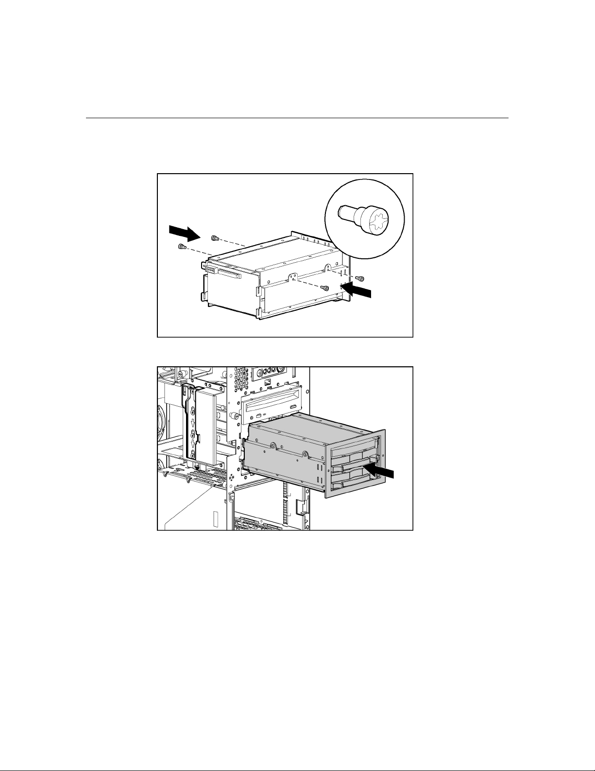
74 HP ProLiant ML370 Generation 4 Server Reference and Troubleshooting Guide
6. Using the T-15 Torx screwdriver attached to the back of the server, position
two screws in the upper mounting holes on each side of the drive cage.
7. Slide the drive cage part of the way into the bay.
IMPORTANT: Be sure that the unit identification numbers (0 and 1)
appear on the right side of the drive cage front panel.
Page 75
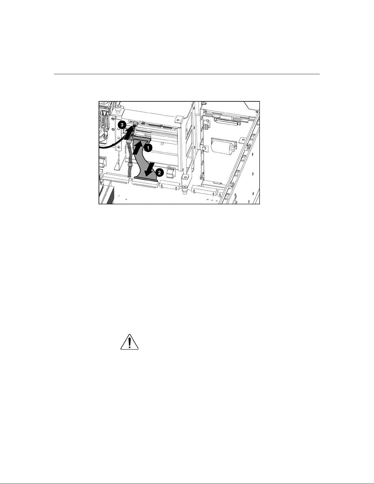
Hardware options installation 75
8. Connect the SCSI and power cables.
9. Slide the drive cage fully into the bay until it is seated securely.
Refer to the HP Internal Two-Bay Hot-Plug SCSI Drive Cage Installation
Instructions for additional information.
Redundant hot-plug fans
The server supports redundant hot-plug fans to provide proper airflow to the
system if a primary fan fails.
In the standard configuration, three fans cool the server: fans 1, 3, and 5.
For the redundant configuration, fans 2, 4, and 6 are added to back up the
primary fans. This configuration allows the server to continue operation in nonredundant mode, if a fan failure occurs.
WARNING: To prevent personal injury from hazardous
energy:
Page 76

76 HP ProLiant ML370 Generation 4 Server Reference and Troubleshooting Guide
Remove watches, rings, or other metal objects. •
• • Use tools with insulated handles.
Do not place tools or metal parts on top of batteries.
NOTE: Fan locations are located in the chassis.
Item Description Configuration
1 Fan 1 Primary
2 Fan 2 Redundant
3 Fan 3 Primary
4 Fan 4 Redundant
5 Fan 5 Primary
6 Fan 6 Redundant
Fan failures are indicated by amber LEDs located on each hot-plug fan and by
the front panel internal health LED. When a fan failure occurs, the internal health
LED illuminates red in non-redundant mode and amber in redundant mode.
Redundant hot-plug fan cage option
For full redundancy, always install all three fans included in the redundant hotplug fan cage option kit. To install the redundant hot-plug fan cage:
Page 77
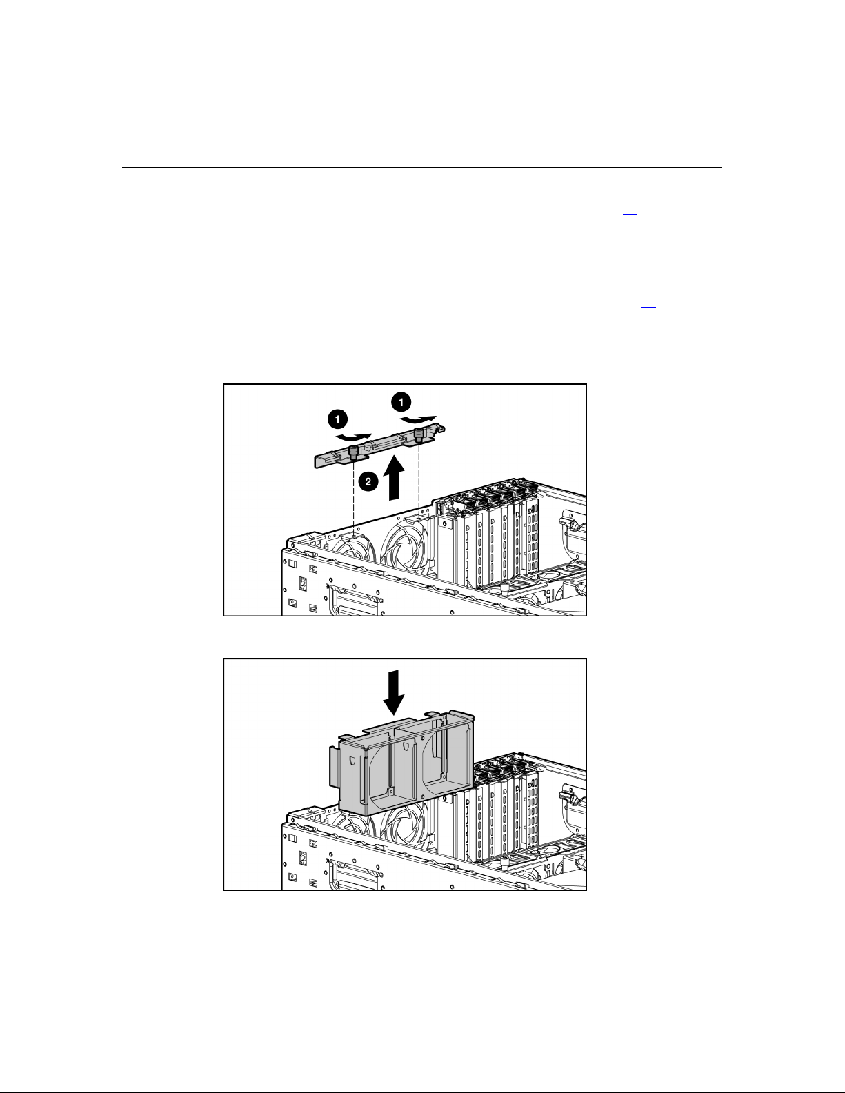
Hardware options installation 77
1. Power down the server ("Powering down the server" on page 27).
2. Extend or remove the server from the rack ("Extending the server from the
rack" on page 28
).
3. Remove the front bezel door, if necessary.
4. Remove the access panel ("Removing the access panel" on page 30
5. Remove the redundant fan cage retaining bracket from the chassis.
IMPORTANT: Do not discard the fan cage retaining bracket. The
bracket is required for proper fan operation.
6. Slide the redundant fan cage into the slots on the chassis wall.
).
Page 78
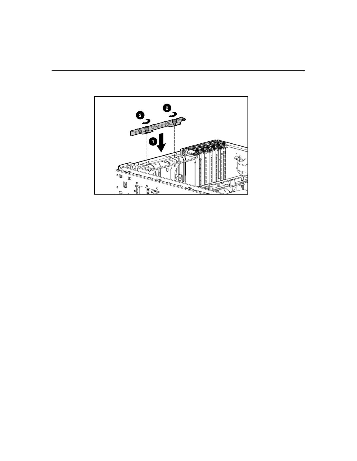
78 HP ProLiant ML370 Generation 4 Server Reference and Troubleshooting Guide
7. Reinstall the redundant fan cage retaining bracket.
Installing hot-plug fans
1. After installing the redundant fan cage, insert two of the hot-plug fans into
the redundant fan cage and one fan into the redundant slot on the fan cage
along the center wall.
Page 79
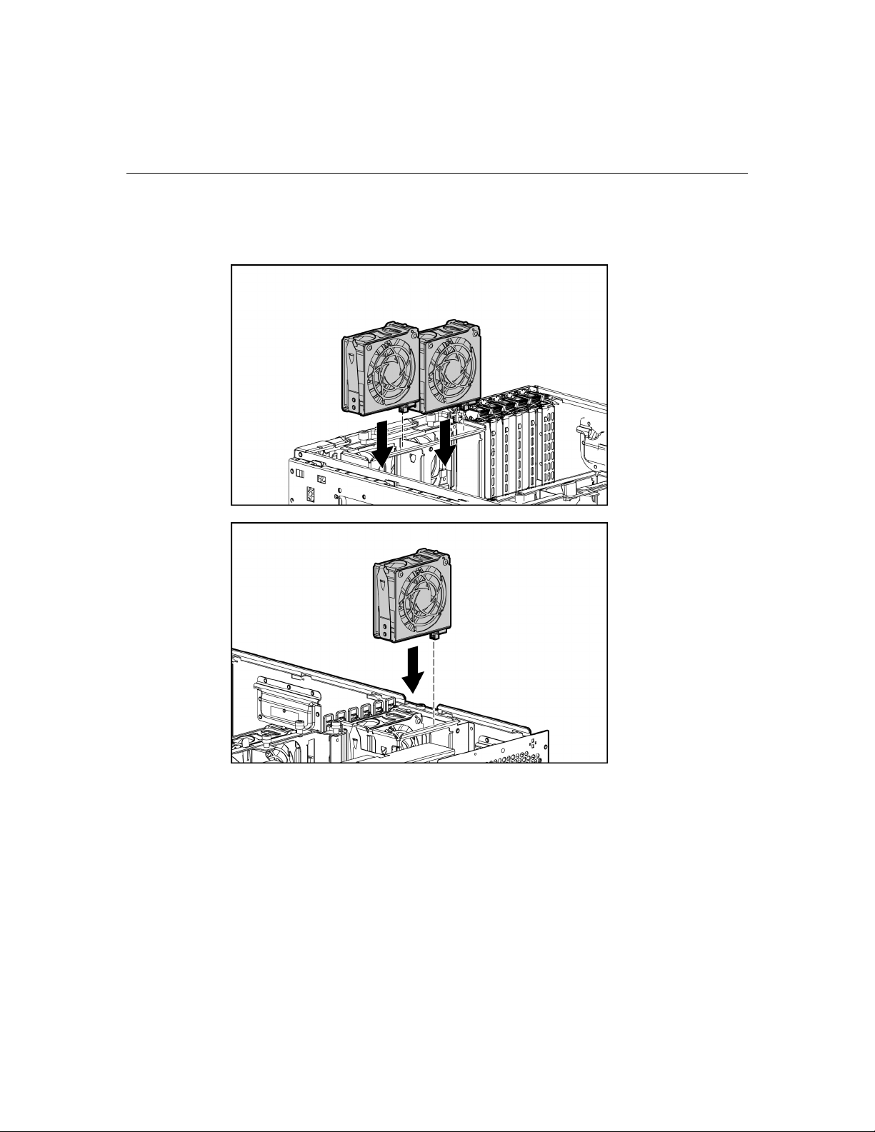
Hardware options installation 79
NOTE: Any hot-plug fan provided in the redundant hot-plug fan cage
option kit can be installed in any of the hot-plug fan slots. Fans are
keyed to fit only one way in the slot.
2. Install other hardware options as needed.
3. Power up the server and observe the internal system health LED on the front
panel and the LEDs on all installed fans to be sure they are green.
NOTE: If the front panel internal system health LED is not green after
you install hot-plug fans, reseat the hot-plug fan or refer to the
troubleshooting section.
Page 80

80 HP ProLiant ML370 Generation 4 Server Reference and Troubleshooting Guide
Replacing hot-plug fans
IMPORTANT: Remove and replace one fan at a time. If the system
detects two fan failures in the same zone, the server shuts down to
avoid thermal damage.
When the optional fan cage and all three redundant fans are installed, individual
fans can be hot-swapped at any time. To replace a hot-plug fan:
1. Install the replacement hot-plug fan, and press down to seat securely.
2. Repeat to replace additional fans as needed.
3. Replace the access panel ("Removing the access panel" on page 30
4. Power up the server and observe the internal system health LED on the front
panel and the LEDs on all installed fans to be sure they are green.
NOTE: If the front panel internal system health LED is not green after
you install hot-plug fans, reseat the hot-plug fan or refer to the
troubleshooting section.
Redundant hot-plug power supply
The server supports a second hot-plug power supply to provide redundant power
to the system in the event of a failure in the primary power supply. You can
install or replace a second hot-plug power supply without powering down the
server.
).
Page 81

Hardware options installation 81
CAUTION: If only one power supply is installed, do not
remove the power supply unless the server has been powered down.
Removing the only operational power supply will cause an immediate
power loss.
1. Remove the T-15 Torx screws. Remove the power supply blank in the
secondary hot-plug power supply bay.
NOTE: The T-15 Torx screwdriver is clipped to the rear panel of the
server.
2. Install the second hot-plug power supply.
Page 82

82 HP ProLiant ML370 Generation 4 Server Reference and Troubleshooting Guide
3. Connect the power cord to the redundant power supply.
4. Use the power cord management clip on the power supply to secure the cord
and form a service loop.
5. Connect the power cord to the power source.
6. Be sure that the power supply LED is green ("Rear panel LEDs and buttons"
on page 13
).
7. Be sure that the front panel external health LED is green ("Front panel LEDs
and buttons" on page 10
IMPORTANT: For maximum server availability, be sure that the two
power supplies are powered by separate AC power sources.
NOTE: If you remove or replace the primary hot-plug power supply, use
the T-15 Torx screwdriver provided with the server to remove the
shipping screw from the upper left corner of the power supply unit.
Expansion boards
The server supports PCI-X and PCI Express expansion boards.
Slot Expansion
card type
1 PCI-X 64-bit, 3.3-volt 100-MHz
2 PCI-X 64-bit, 3.3-volt 100-MHz
).
Connector Capable speed
Page 83

Hardware options installation 83
Slot Expansion
card type
3 PCI-X 64-bit, 3.3-volt 100-MHz
4 PCI-X 64-bit, 3.3-volt 100-MHz
5 PCI Express * x8 x4
6 PCI Express * x8 x4
* x8 PCI Express cards are supported, but will run at x4 speeds.
Performance balancing
Balancing is the paired arrangement of expansion boards for optimal
performance based on the bus architecture of the expansion slots. When
populating boards on a shared bus, be sure that both boards operate at the same
speed (two PCI boards or two PCI-X boards). If boards with different speeds are
used, the bus performs at the speed of the slowest board. Performance balancing
is not necessary with PCI Express slots.
To balance expansion board performance, populate slots across different buses
before populating two slots on the same bus.
NOTE: The population order is only a recommendation. Expansion
boards can reside in any slot.
Slot Number Population Order PCI-X Bus Sharing
Connector Capable speed
1 1 Slots 1 and 2 shared PCI-X bus
2 3 Slots 1 and 2 shared PCI-X bus
3 2 Slots 3 and 4 shared PCI-X bus
4 4 Slots 3 and 4 shared PCI-X bus
NOTE: The operating system detects expansion devices in the
following order: 1-2-3-4-5-6.
Removing the expansion slot cover
1. Power down the server ("Powering down the server" on page 27).
Page 84

84 HP ProLiant ML370 Generation 4 Server Reference and Troubleshooting Guide
2. Extend or remove the server from the rack ("Extending the server from the
rack" on page 28
).
3. Remove the front bezel door, if necessary.
4. Remove the access panel ("Removing the access panel" on page 30
5. Remove the expansion slot cover.
CAUTION: To prevent improper cooling and thermal damage,
do not operate the server unless all PCI slots have either an expansion
slot cover or an expansion board installed.
To replace the component, reverse the removal procedure.
).
Installing expansion boards
CAUTION: To prevent damage to the server or expansion
boards, power down the server and remove all AC power cords before
removing or installing the expansion boards.
To install an expansion board:
1. Remove the expansion slot cover ("Removing the expansion slot cover" on
page 83
).
Page 85

Hardware options installation 85
2. Release the retaining clip.
3. Install the expansion board.
Page 86

86 HP ProLiant ML370 Generation 4 Server Reference and Troubleshooting Guide
4. Lock the retaining clip.
5. Connect any required internal or external cables to the expansion board.
Refer to the documentation that ships with the expansion board.
Remote Insight Lights-Out Edition II board
The server comes with iLO remote management capability embedded on the
system board. The 30-pin remote management connector for the RILOE II board
is provided to reduce external cabling. The 30-pin connector provides power,
keyboard, mouse, and other peripheral signals directly to the system board;
therefore, the external AC power adapter and keyboard/mouse loopback cable are
not needed for normal operations.
The RILOE II board provides remote server manageability for ProLiant servers.
It can be accessed from a network client using a standard web browser and it
provides a keyboard, mouse, and video capability for a host server, regardless of
the state of the host operating system or host server. The RILOE II board features
include a faster processor for increased performance, new user interface for
easier browsing, integration with LDAP, Virtual Floppy, and Virtual CD for
increased server manageability.
Page 87

Hardware options installation 87
A built-in processor, memory, NIC, ROM, and standard external power supply
make the RILOE II board independent of the host server and its operating
system. This design allows the RILOE II board to provide remote access to any
authorized network client, to send alerts, and to perform other management
functions.
For information about iLO technology, refer to "Integrated Lights-Out
Technology (on page 120
IMPORTANT: Install the RILOE II board into slot 1 for ease of cabling.
)."
For information about RILOE II cabling, refer to "RILOE II Cabling (on page
107
)."
VHDCI or HD68 SCSI cable option
The VHDCI or HD68 SCSI Cable connects the server to external SCSI-based
storage or backup devices. The cabling option kit must be used for internal ports
to be used externally.
IMPORTANT: To install the external SCSI option, an internal SCSI port
must be dedicated for external use only.
In addition to the VHDCI or HD68 SCSI cable, you will also need:
• • T-15 Torx screwdriver
Flat-head screwdriver
NOTE: A PCI blank included with the optional Internal-to-External SCSI
Kit enables the optional HD68 SCSI cable to connect through a PCI-X
or PCI Express expansion slot ("Expansion boards" on page 82
"Installing expansion boards" on page 84). Refer to the Internal-toExternal SCSI Kit installation instructions for details.
,
To prepare the server before installing or removing options:
1. Power down the server ("Powering down the server" on page 27
).
2. Extend or remove the server from the rack ("Extending the server from the
rack" on page 28
).
3. Remove the front bezel door, if necessary.
4. Remove the access panel ("Removing the access panel" on page 30
).
Page 88

88 HP ProLiant ML370 Generation 4 Server Reference and Troubleshooting Guide
WARNING: To reduce the risk of electric shock or damage
to the equipment, disconnect power from the server by unplugging
all power cords from the electrical outlets.
CAUTION: Failure to correctly power down the server could
result in damage to equipment or loss of information.
5. Using a T-15 Torx screwdriver, remove a SCSI knockout located on the rear
of the chassis and retain the screw.
6. Connect the preassembled cable bracket assembly through the external SCSI
knockout on the rear of the chassis and secure the cable using the screw
retained in step 3.
7. Connect the other end of the VHDCI SCSI cable to an available SCSI port,
or the other end of the HD68 SCSI cable to a PCI blank.
NOTE: Refer to the documentation that shipped with the external
storage device for more information.
Replace the access panel ("Removing the access panel" on page 30).
Page 89

Hardware options installation 89
Duplex SCSI board option
The server supports an optional duplex SCSI board supplied with the Duplex
SCSI Backplane Option Kit. The duplex SCSI board allows four hard drives to
be supported on one SCSI bus, and two hard drives to be supported on the other
SCSI bus. For cabling information, refer to "Server Cabling (on page 99)."
To prepare the server before installing or removing options:
1. Power down the server ("Powering down the server" on page 27
2. Extend or remove the server from the rack ("Extending the server from the
rack" on page 28
3. Remove the front bezel door, if necessary.
4. Remove the access panel ("Removing the access panel" on page 30
5. Remove the SCSI simplex cable.
).
).
).
Page 90

90 HP ProLiant ML370 Generation 4 Server Reference and Troubleshooting Guide
6. Install the duplex SCSI board.
Tower-to-rack conversion option
Converting a tower server to a rack server (on page 90)
Installing the rack server (on page 97
Accessing the server in the rack (on page 97
Converting a tower server to a rack server
The tower-to-rack conversion kit includes all equipment required to convert the
tower model server into a rack model server, and to install the server into most
square- or round-hole racks.
The tower-to-rack conversion kit includes:
•
Rack rails
•
Cable management arm
•
Server rails
)
)
•
Screw retaining plate
Page 91

Hardware options installation 91
•
Cage nuts
•
Rack template
•
Server bezel for rack environment
In addition to the supplied items, you may need a T-15 Torx screwdriver, which
is attached to the rear of the server.
Before converting a tower server to a rack server:
1. Power down the server ("Powering down the server" on page 27
).
2. Remove the front bezel door, if necessary.
3. Remove the access panel ("Removing the access panel" on page 30
4. Remove the feet.
5. Remove the tower configuration panel:
a. Use the Torx T-15 screwdriver to remove the two front panel screws.
).
Page 92
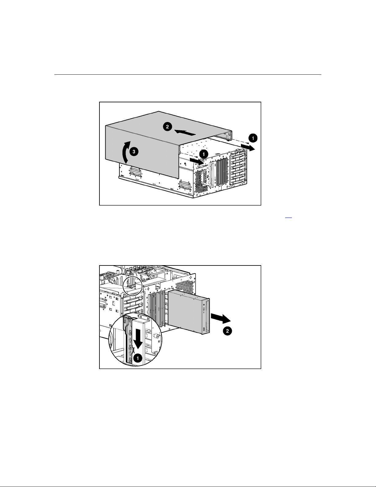
92 HP ProLiant ML370 Generation 4 Server Reference and Troubleshooting Guide
b. Remove the tower configuration panel.
6. Remove the access panel ("Removing the access panel" on page 30
7. Rotate the CD-ROM drive and media drive blanks.
a. Press and slide the media latch.
b. Release the CD-ROM drive from the back and push it forward to better
access the cables.
).
Page 93
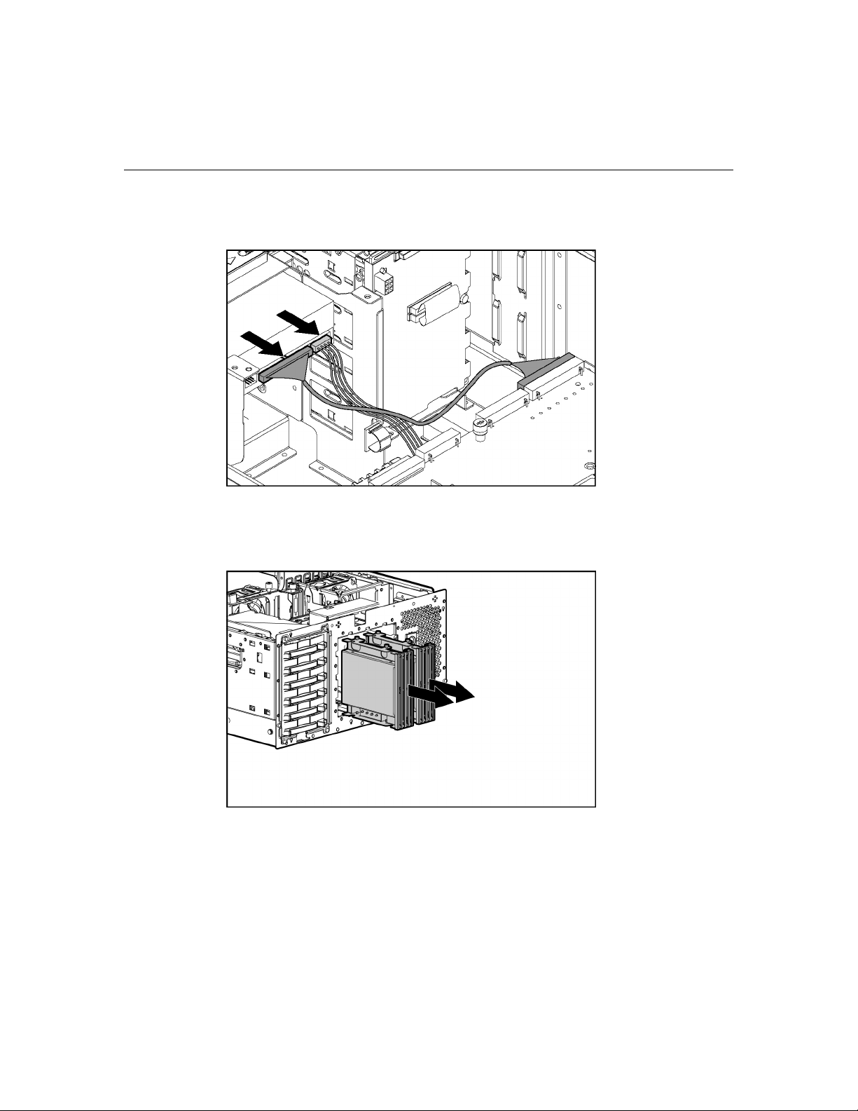
Hardware options installation 93
8. Remove the IDE CD-ROM drive cable and power cable from the back of the
drive.
9. Remove the CD-ROM drive.
10. Remove the media blanks by pressing and sliding the media latch for each
blank.
Page 94
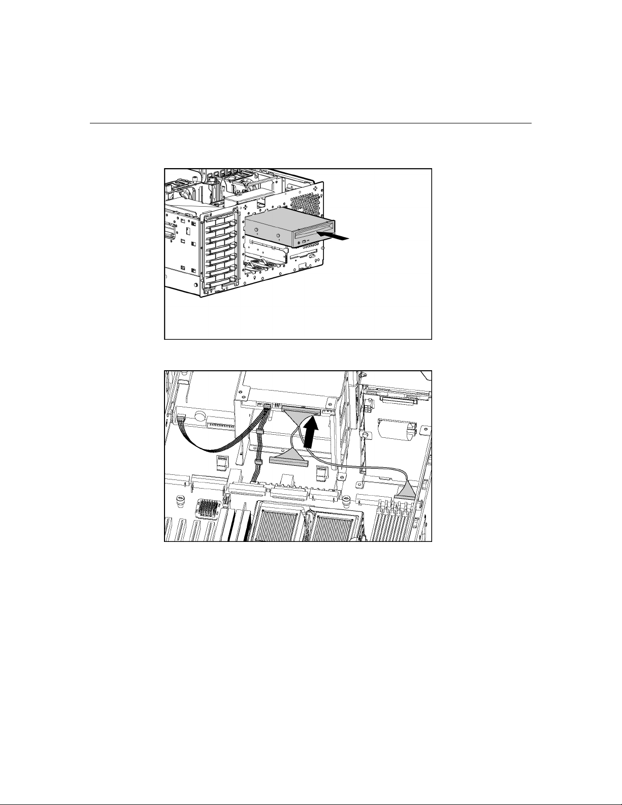
94 HP ProLiant ML370 Generation 4 Server Reference and Troubleshooting Guide
11. Partially reinsert the CD-ROM drive horizontally into the top slot of the bay.
12. Reconnect the IDE CD-ROM drive cable and power cable.
Page 95
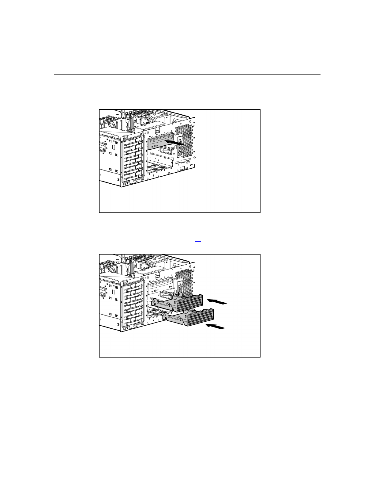
Hardware options installation 95
13. Push the CD-ROM drive all the way into the bay until the locking latch
clicks into place, securing the drive.
14. Install the media blanks horizontally in the bay below the CD-ROM drive.
NOTE: Install any optional tape drives ("Installing a half-height or fullheight media device" on page 70) instead of the media blanks at this
time.
Page 96

96 HP ProLiant ML370 Generation 4 Server Reference and Troubleshooting Guide
15. Remove the two clips on the server.
16. Align the five spools on the rack bezel with the keyholes on the metal frame,
and install the rack bezel.
Page 97

Hardware options installation 97
17. Tighten both internal rack bezel thumbscrews.
18. Replace the access panel ("Removing the access panel" on page 30
Installing the rack server
1. Install the server into a rack. ("Installing the server into the rack" on page 42)
2. Connect the power cord and peripheral devices. Use the power supply
retaining clip to secure the power cord. Refer to "Rear Panel Components (on
page 12
)" for connector locations.
3. Power up the server ("Powering up the server" on page 27
4. Install the operating system ("Installing the operating system" on page 50
5. Register the server. To register a server, refer to the registration card in the
HP ProLiant Essentials Foundation Pack or the HP Registration website
(http://register.hp.com
).
Accessing the server in the rack
Some installation or maintenance procedures may require the server to be
extended from the rack ("Extending the server from the rack" on page 28
performing.
If the maintenance procedure requires accessing the server rear panel:
).
).
).
) before
Page 98

98 HP ProLiant ML370 Generation 4 Server Reference and Troubleshooting Guide
1. Unlock the cable management arm and swing the arm away from the server.
2. Reverse step 1 to secure the cable management arm after the maintenance
procedures have been completed.
Page 99

99
Server cabling
In this section
Storage device cabling guidelines ................................................................................................99
Hot-plug SCSI cabling..................................................................................................................99
Cable connector identification....................................................................................................106
CD-ROM drive cabling ..............................................................................................................107
RILOE II cabling........................................................................................................................107
Diskette drive cabling.................................................................................................................108
External storage cabling .............................................................................................................109
Storage device cabling guidelines
CAUTION: To prevent damage to the equipment, be sure that
the server is powered down, all cables are disconnected from the back
of the server, and the power cord is disconnected from the grounded
(earthed) AC outlet before installing devices.
CAUTION: To prevent damage to electrical components,
properly ground the server before beginning any installation procedure.
Improper grounding can cause electrostatic discharge.
Hot-plug SCSI cabling
Integrated Simplex SCSI Cabling (on page 100)
Integrated Duplex SCSI Cabling (on page 101
Array Controller Simplex SCSI Cabling (on page 102
Array Controller Duplex SCSI Cabling (on page 102
Integrated SCSI Cabling with Optional Internal Two-Bay Hot-Plug SCSI Drive
Cage (on page 104
)
)
)
)
Page 100

100 HP ProLiant ML370 Generation 4 Server Reference and Troubleshooting Guide
Array Controller SCSI Cabling with Optional Internal Two-Bay Hot-Plug SCSI
Drive Cage (on page 105
)
Integrated simplex SCSI cabling
In the integrated simplex cabling configuration, which is the standard shipping
configuration, the integrated SCSI controller controls up to six hard drives
through one SCSI port.
NOTE: The cables shown ship standard with the server.
Item Component description SCSI IDs managed
1 SCSI cable (SCSI 1) 0, 1, 2, 3, 4, 5
2 simplex SCSI cable N/A
IMPORTANT: After changing any SCSI configuration, be sure the
proper boot controller order is set in RBSU.
 Loading...