

Page 1

HP ProLiant ML370 Generation 4 Server Maintenance and Service Guide
March 2006 (Eighth Edition)
Part Number 346895-008
Page 2

© Copyright 2004, 2006 Hewlett-Packard Development Company, L.P.
The information contained herein is subject to change without notice. The only warranties for HP products and services are set forth in the express
limited warranty statements accompanying such products and services. Nothing herein should be construed as constituting an additional
warranty. HP shall not be liable for technical or editorial errors or omissions contained herein.
Microsoft, Windows, and Windows NT are US registered trademarks of Microsoft Corporation. Windows Server 2003 is a trademark of
Microsoft Corporation.
Intel and Xeon are trademarks or registered trademarks of Intel Corporation or its subsidiaries in the United States and other countries.
Linux is a U.S. registered trademark of Linus Torvalds.
March 2006 (Eighth Edition)
Part Number 346895-008
Audience assumptions
This document is for the person who installs, administers, and troubleshoots servers and storage systems.
HP assumes you are qualified in the servicing of computer equipment and trained in recognizing hazards
in products with hazardous energy levels.
Page 3

Contents
Illustrated parts catalog ................................................................................................................. 6
Customer self repair................................................................................................................................... 6
Mechanical components............................................................................................................................. 7
System components ...................................................................................................................................8
Removal and replacement procedures........................................................................................... 13
Required tools......................................................................................................................................... 13
Safety considerations............................................................................................................................... 14
Preventing electrostatic discharge .................................................................................................... 14
Symbols on equipment ................................................................................................................... 14
Rack warnings ..............................................................................................................................15
Preparation procedures............................................................................................................................ 15
Power down the server................................................................................................................... 16
Extending the server from the rack ................................................................................................... 16
Removing the server from the rack ...................................................................................................17
Feet....................................................................................................................................................... 17
Front bezel ............................................................................................................................................. 19
Access panel .......................................................................................................................................... 20
Rack bezel .............................................................................................................................................20
Tower hood cover ................................................................................................................................... 21
Rack rails ............................................................................................................................................... 22
Power supply blank ................................................................................................................................. 23
Hot-plug power supply.............................................................................................................................23
Hard drive blank (SCSI) ...........................................................................................................................24
Hard drives (SCSI)................................................................................................................................... 25
Hard drive cage (SCSI) ............................................................................................................................ 25
Hard drive blank (SAS) ............................................................................................................................ 26
Hard drives (SAS) ................................................................................................................................... 27
Hard drive cage (SAS)............................................................................................................................. 28
System fans ............................................................................................................................................ 29
Redundant hot-plug fan cage .................................................................................................................... 30
Expansion slot cover................................................................................................................................32
Slot release lever..................................................................................................................................... 33
Expansion board..................................................................................................................................... 33
Processor air baffle.................................................................................................................................. 34
Center wall............................................................................................................................................. 35
CD-ROM drive........................................................................................................................................ 36
Power button/LED assembly...................................................................................................................... 37
Diskette drive.......................................................................................................................................... 38
Processor assembly.................................................................................................................................. 39
Processor power module (PPM) ................................................................................................................. 42
DIMM.................................................................................................................................................... 43
SCSI backplane ...................................................................................................................................... 44
Duplex SCSI board.................................................................................................................................. 45
VHDCI or HD68 SCSI cable option ........................................................................................................... 46
Power supply backplane ..........................................................................................................................47
System board ......................................................................................................................................... 48
Battery................................................................................................................................................... 49
Re-entering the server serial number and product ID..................................................................................... 50
Server cabling............................................................................................................................ 51
Contents 3
Page 4

Cabling overview.................................................................................................................................... 51
Hot-plug SCSI cabling.............................................................................................................................. 51
Integrated simplex SCSI cabling ...................................................................................................... 51
Integrated duplex SCSI cabling ....................................................................................................... 52
Integrated SCSI cabling with optional internal two-bay hot-plug SCSI drive cage ...................................53
Array controller simplex SCSI cabling ..............................................................................................54
Array controller duplex SCSI cabling ............................................................................................... 54
Array controller duplex SCSI cabling with optional internal two-bay hot-plug SCSI drive cage ................. 55
SAS cabling ...........................................................................................................................................55
CD-ROM drive cabling............................................................................................................................. 57
Diskette drive cabling .............................................................................................................................. 57
External storage cabling........................................................................................................................... 58
Storage device cabling guidelines.............................................................................................................58
RILOE II cabling ......................................................................................................................................58
Diagnostic tools.......................................................................................................................... 60
Automatic Server Recovery ....................................................................................................................... 60
HP Systems Insight Manager..................................................................................................................... 60
Integrated Management Log ..................................................................................................................... 60
Lights Out Manager technology ................................................................................................................ 61
Option ROM Configuration for Arrays ....................................................................................................... 61
ProLiant Essentials Rapid Deployment Pack ................................................................................................. 61
HP ROM-Based Setup Utility ..................................................................................................................... 62
ROMPaq utility........................................................................................................................................ 62
System Online ROM flash component utility ................................................................................................ 62
SmartStart software ................................................................................................................................. 62
SmartStart Scripting Toolkit ............................................................................................................. 63
HP Insight Diagnostics.................................................................................................................... 63
Server component identification.................................................................................................... 64
Front panel components ........................................................................................................................... 64
Front panel LEDs and buttons .................................................................................................................... 65
Rear panel components............................................................................................................................ 66
Rear panel LEDs and buttons..................................................................................................................... 66
System board components........................................................................................................................ 68
System maintenance switch............................................................................................................. 68
Power supply backplane LED ..........................................................................................................69
DIMM slots ................................................................................................................................... 70
System board LEDs .................................................................................................................................. 70
System LEDs and internal health LED combinations....................................................................................... 71
Hot-plug SCSI hard drive LEDs ..................................................................................................................72
SATA or SAS hard drive LEDs ................................................................................................................... 73
Identifying redundant hot-plug fans............................................................................................................ 73
Hot-plug fan LEDs .................................................................................................................................... 74
Specifications............................................................................................................................. 75
Server specifications................................................................................................................................75
Environmental specifications ..................................................................................................................... 75
Hot-plug power supply calculations............................................................................................................ 76
DDR2 SDRAM DIMM specifications ........................................................................................................... 76
1.44-MB diskette drive specifications ......................................................................................................... 76
CD-ROM drive specifications .................................................................................................................... 77
Ultra320 SCSI hard drive specifications ..................................................................................................... 78
SAS and SATA hard drive specifications .................................................................................................... 78
Contents 4
Page 5

Acronyms and abbreviations........................................................................................................ 79
Index......................................................................................................................................... 82
Contents 5
Page 6

Illustrated parts catalog
In this section
Customer self repair ................................................................................................................................. 6
Mechanical components ........................................................................................................................... 7
System components .................................................................................................................................. 8
Customer self repair
What is customer self repair?
HP's customer self-repair program offers you the fastest service under either warranty or contract. It
enables HP to ship replacement parts directly to you so that you can replace them. Using this program,
you can replace parts at your own convenience.
A convenient, easy-to-use program:
• An HP support specialist will diagnose and assess whether a replacement part is required to address
a system problem. The specialist will also determine whether you can replace the part.
• Replacement parts are express-shipped. Most in-stock parts are shipped the very same day you
contact HP. You may be required to send the defective part back to HP, unless otherwise instructed.
• Available for most HP products currently under warranty or contract. For information on the warranty
service, refer to the HP website
(http://h18004.www1.hp.com/products/servers/platforms/warranty/index.html
For more information about HP's customer self-repair program, contact your local service provider. For the
North American program, refer to the HP website (http://www.hp.com/go/selfrepair
Customer replaceable parts are identified in the following tables.
).
).
Illustrated parts catalog 6
Page 7

Mechanical components
Item Description
Original
spare part
number
Modified spare
part number
Customer self
repair (on
page 6)
1 Access panel (top cover) 359233-001 — Yes
2 Front bezel (tower model only) 359234-001 — Yes
3 Rack bezel (rack model only) 359235-001 — Yes
4 Hood cover (tower model only) 359236-001 — Yes
5
Feet (tower model only) (part of kit
— — Yes
365962-001)
6 Removable media blanks 359715-001 — Yes
7 Hard drive blank — — —
a) SCSI 122759-001 — Yes
b) SAS* 392613-001 — Yes
8 Power supply blank 359716-001 — Yes
9 T-15 Torx screwdriver 290557-001 — Yes
*Not shown
Illustrated parts catalog 7
Page 8

System components
Item Description
10 Power supply, 800 W
11 Fan, 92 mm 231213-001 — Yes
12 3.3-V lithium battery 153099-001 — Yes
13 Power button/switch with cable 359714-001 — Yes
14 Processor with heatsink — — —
System components
a) Intel® Xeon™ 3.0-GHz 1-MB L2
cache* †
b) Intel® Xeon™ 3.2-GHz 1-MB L2
cache* †
Original spare part
number
347883-001‡ See
requirement
378006-001 — Yes
374233-001 — Yes
Modified
spare part
number
406867-001 Yes
Customer self
repair (on
page 6)
Illustrated parts catalog 8
Page 9

Item Description
15
16 PPM 347884-001 — Yes
17 Power supply backplane
18 Drive backplane — — —
c) Intel® Xeon™ 3.4-GHz 1-MB L2
cache †
d) Intel® Xeon™ 3.6-GHz 1-MB L2
cache* †
e) Intel® Xeon™ 2.8-GHz 2-MB L2
cache* †
f) Intel® Xeon™ 3.0-GHz 2-MB L2
cache* †
g) Intel® Xeon™ 3.2-GHz 2-MB L2
cache* †
h) Intel® Xeon™ 3.4-GHz 2-MB L2
cache* †
i) Intel® Xeon™ 3.6-GHz 2-MB L2
cache* †
j) Intel® Xeon™ 3.8-GHz 2-MB L2
cache* †
k) Intel® Xeon™ dual-core, 1066-Mhz
FSB, 4-MB cache for use with dual-core
system I/O board 012974-001 only
Boards
a) System board with processor cage
(for use with Intel® Xeon™ single-core
processors)
b) System board, dual-core processor
support, with processor cage & battery
(for use with Intel® Xeon™ dual-core
processors)
Original spare part
number
364757-001 — Yes
364758-001 — Yes
399132-001 — Yes
379427-001 — Yes
379428-001 — Yes
379429-001 — Yes
379430-001 — Yes
399133-001 — Yes
403934-001 — Yes
347882-001 — Yes
408300-001‡ See
requirement
347886-001‡ See
requirement
Modified
spare part
number
408300-001 Yes
412735-001 Yes
Customer self
repair (on
page 6)
19 Diskette drive, 3-mode, 1.44 MB
20 CD-ROM drive, IDE, 48x
21 Plastics kit 365962-001 — —
a) SCSI backplane Simplex with 6 x 1in drive cage
b) SCSI backplane Duplex board with
drive cage*
c) SAS backplane Duplex board with
drive cage*
Mass storage devices
Miscellaneous
a) Foot (refer to item number 5)* — — Yes
359719-001 — Yes
371722-001 — Yes
392607-001‡ See
requirement
233409-001‡ See
requirement
288894-001‡ See
requirement
412736-001 Yes
399397-001 Yes
397931-001 Yes
Illustrated parts catalog 9
Page 10

Item Description
22 Hardware kit 365963-001 — —
23 Wall, center 359238-001 — Yes
24 Rack-mounting kit* 359239-001 — Yes
25 Cable management arm* 367831-001 — Yes
26 Country kit* 359712-001 — Yes
27 Return kit — — —
28 Processor air baffle 359240-001 — Yes
b) Receptacle, door snap, stone* — — Yes
c) Retainer, card guide, PCI — — Yes
d) Fastener, 0.15-in plastic standoff* — — Yes
e) Fastener, 0.202-in plastic standoff* — — Yes
f) Clip, cable, adhesive, 1.77 in* — — Yes
g) Clip, retainer, 0.125-in diameter* — — Yes
h) Assembly, PCI latch and base — — Yes
i) Cable clip* — — Yes
j) Standoff bumper* — — Yes
a) Bracket, rear, removable — — Yes
b) Bracket, diskette tray* — — Yes
c) Bracket, diskette retainer* — — Yes
d) Cover, slot, PCI expansion* — — Yes
e) Bracket, blank, option board, PCI
latch*
f) 2-56 pan head screw* — — Yes
g) Hi-top screw* — — Yes
a) Tower*, packing box and cushions 359713-001 — Yes
b) Rack*, packing box and cushions 371561-001 — Yes
Cables
Original spare part
number
— — Yes
Modified
spare part
number
Customer self
repair (on
page 6)
29 Miscellaneous data cable kit* 365964-001 — —
30 Miscellaneous power cable kit (SCSI)* 365967-001 — —
a) IDE hard drive/CD-ROM drive data
cable*
b) Diskette drive cable* — — Yes
c) Point-to-point SCSI cable* — — Yes
d) USB cable assembly* — — Yes
a) Diskette and CD-ROM drive power
cable (SCSI)*
b) Power supply cable, 24 pin* — — Yes
— — Yes
— — Yes
Illustrated parts catalog 10
Page 11

Item Description
31 Miscellaneous power cable kit (SAS)* 392608-001 — —
32 SAS option cable* 389952-001 — Yes
33 a) 512-MB PC2-3200R DIMM
34 Rear fan cage 230984-001 — Yes
35
36 Keyboard*
37 Mouse*
38 AC power cord* 187335-001 — Yes
39
40 SAS SFF hard drive* — — —
c) Fan cage cable* — — Yes
a) Diskette and CD-ROM drive power
cable (SAS)*
Memory
b) 1-GB PC2-3200R DIMM*
c) 2-GB PC2-3200R DIMM*
d) 4-GB PC2-3200R DIMM
Options
Two-bay, hot-plug SCSI hard drive
cage*
SCSI Ultra320 universal hot-plug hard
drive*
a) 72.8-GB, 10,000 rpm
b) 146.8-GB, 10,000 rpm
c) 300-GB, 10,000 rpm
e) 36.4-GB, 15,000 rpm
f) 72.8-GB, 15,000 rpm
g) 146-GB, 15,000 rpm
Original spare part
number
— — Yes
359241-001‡ See
requirement
359242-001‡ See
requirement
359243-001‡ See
requirement
379984-001‡ See
requirement
253761-001 — Yes
311059-001‡ See
requirement
311060-001‡ See
requirement
— — —
289042-001‡ See
requirement
289044-001‡ See
requirement
351126-001‡ See
requirement
289241001‡ See
requirement
289243-001‡ See
requirement
347779-001‡ See
requirement
Modified
spare part
number
413384-001 Yes
413385-001 Yes
413386-001 Yes
413388-001 Yes
382925-001 Yes
390937-001 Yes
404709-001 Yes
404708-001 Yes
404701-001 Yes
404714-001 Yes
404713-001 Yes
404712-001 Yes
Customer self
repair (on
page 6)
41 HP Smart Array P600 Controller 370855-001 — Yes
a) 36-GB, 10,000 rpm 376596-001 — Yes
b) 72-GB, 10,000 rpm 376597-001 — Yes
c) 60-GB, 5,000 rpm SFF SATA 382264-001 — Yes
Illustrated parts catalog 11
Page 12

* Not shown
†Do not mix single-core and dual-core processors, or processors with different cache sizes or speeds.
‡REQUIREMENT:
For Customers in the EU only.
The use of the Original Spare part is regulated by RoHS legislation§.
If your unit contains a part that is labelled with the Modified Spare number, the Modified Spare must be ordered as
the replacement part in the EU.
If your unit contains a part that is labelled with the Original Spare number, please order the Original Spare as the
replacement part in the EU. In this case either the Original Spare or the Modified Spare may be shipped which will
not affect performance or functionality of the unit.
§Directive 2002/95/EC restricts the use of lead, mercury, cadmium, hexavalent chromium, PBBs and PBDEs in
electronic products.
Illustrated parts catalog 12
Page 13

Removal and replacement procedures
In this section
Required tools........................................................................................................................................ 13
Safety considerations.............................................................................................................................. 14
Preparation procedures........................................................................................................................... 15
Feet ...................................................................................................................................................... 17
Front bezel ............................................................................................................................................ 19
Access panel ......................................................................................................................................... 20
Rack bezel ............................................................................................................................................ 20
Tower hood cover .................................................................................................................................. 21
Rack rails .............................................................................................................................................. 22
Power supply blank ................................................................................................................................ 23
Hot-plug power supply............................................................................................................................ 23
Hard drive blank (SCSI) .......................................................................................................................... 24
Hard drives (SCSI).................................................................................................................................. 25
Hard drive cage (SCSI)........................................................................................................................... 25
Hard drive blank (SAS)........................................................................................................................... 26
Hard drives (SAS) .................................................................................................................................. 27
Hard drive cage (SAS)............................................................................................................................ 28
System fans ........................................................................................................................................... 29
Redundant hot-plug fan cage ................................................................................................................... 30
Expansion slot cover............................................................................................................................... 32
Slot release lever.................................................................................................................................... 33
Expansion board.................................................................................................................................... 33
Processor air baffle................................................................................................................................. 34
Center wall............................................................................................................................................ 35
CD-ROM drive ....................................................................................................................................... 36
Power button/LED assembly .................................................................................................................... 37
Diskette drive......................................................................................................................................... 38
Processor assembly................................................................................................................................. 39
Processor power module (PPM)................................................................................................................ 42
DIMM................................................................................................................................................... 43
SCSI backplane ..................................................................................................................................... 44
Duplex SCSI board................................................................................................................................. 45
VHDCI or HD68 SCSI cable option .......................................................................................................... 46
Power supply backplane ......................................................................................................................... 47
System board...................................................................................................................
Battery .................................................................................................................................................. 49
Re-entering the server serial number and product ID ................................................................................... 50
...................... 48
Required tools
You need the following items for some procedures:
Removal and replacement procedures 13
Page 14
•
T-15 Torx screwdriver (included with the server)
• Diagnostics Utility (included on the SmartStart CD-ROM)
Safety considerations
Before performing service procedures, review all the safety information.
Preventing electrostatic discharge
To prevent damaging the system, be aware of the precautions you need to follow when setting up the
system or handling parts. A discharge of static electricity from a finger or other conductor may damage
system boards or other static-sensitive devices. This type of damage may reduce the life expectancy of the
device.
To prevent electrostatic damage:
• Avoid hand contact by transporting and storing products in static-safe containers.
• Keep electrostatic-sensitive parts in their containers until they arrive at static-free workstations.
• Place parts on a grounded surface before removing them from their containers.
• Avoid touching pins, leads, or circuitry.
• Always be properly grounded when touching a static-sensitive component or assembly.
Symbols on equipment
The following symbols may be placed on equipment to indicate the presence of potentially hazardous
conditions.
This symbol indicates the presence of hazardous energy circuits or electric shock
hazards. Refer all servicing to qualified personnel.
WARNING: To reduce the risk of injury from electric shock hazards, do not open
this enclosure. Refer all maintenance, upgrades, and servicing to qualified personnel.
This symbol indicates the presence of electric shock hazards. The area contains no
user or field serviceable parts. Do not open for any reason.
WARNING: To reduce the risk of injury from electric shock hazards, do not open
this enclosure.
This symbol on an RJ-45 receptacle indicates a network interface connection.
WARNING: To reduce the risk of electric shock, fire, or damage to the equipment,
do not plug telephone or telecommunications connectors into this receptacle.
This symbol indicates the presence of a hot surface or hot component. If this surface is
contacted, the potential for injury exists.
WARNING: To reduce the risk of injury from a hot component, allow the surface to
cool before touching.
Removal and replacement procedures 14
Page 15
This symbol indicates that the component exceeds the recommended weight for one
25-41 kg
55-90 lbs
individual to handle safely.
WARNING: To reduce the risk of personal injury or damage to the equipment,
observe local occupational health and safety requirements and guidelines for manual
material handling.
These symbols, on power supplies or systems, indicate that the equipment is supplied
by multiple sources of power.
WARNING: To reduce the risk of injury from electric shock, remove all power
cords to completely disconnect power from the system.
Rack warnings
WARNING: To reduce the risk of personal injury or damage to the equipment, be sure
that:
• The leveling jacks are extended to the floor.
• The full weight of the rack rests on the leveling jacks.
• The stabilizing feet are attached to the rack if it is a single-rack installation.
• The racks are coupled together in multiple-rack installations.
• Only one component is extended at a time. A rack may become unstable if more than
one component is extended for any reason.
WARNING: To reduce the risk of personal injury or equipment damage when unloading
a rack:
• At least two people are needed to safely unload the rack from the pallet. An empty
42U rack can weigh as much as 115 kg (253 lb), can stand more than 2.1 m (7 ft)
tall, and may become unstable when being moved on its casters.
• Never stand in front of the rack when it is rolling down the ramp from the pallet.
Always handle the rack from both sides.
WARNING: To reduce the risk of personal injury or damage to the equipment,
adequately stabilize the rack before extending a component outside the rack. Extend
only one component at a time. A rack may become unstable if more than one component
is extended.
WARNING: When installing a server in a telco rack, be sure that the rack frame is
adequately secured to the top and bottom of the building structure.
Preparation procedures
To access some components and perform certain service procedures, you must perform one or more of the
following procedures:
• Extend the server from the rack ("Extending the server from the rack" on page 16).
If you are performing service procedures in an HP, Compaq branded, telco, or third-party rack
cabinet, you can use the locking feature of the rack rails to support the server and gain access to
internal components.
For more information about telco rack solutions, refer to the RackSolutions.com website
(http://www.racksolutions.com/hp
• Power down the server (on page 16).
).
Removal and replacement procedures 15
Page 16

If you must remove a server from a rack or a non-hot-plug component from a server, power down the
server.
• Remove the server from the rack ("Removing the server from the rack" on page 17).
If the rack environment, cabling configuration, or the server location in the rack creates awkward
conditions, remove the server from the rack.
Power down the server
WARNING: To reduce the risk of personal injury, electric shock, or damage to the
equipment, remove the power cord to remove power from the server. The front panel
Power On/Standby button does not completely shut off system power. Portions of the
power supply and some internal circuitry remain active until AC power is removed.
IMPORTANT: If installing a hot-plug device, it is not necessary to power down the server.
1. Shut down the OS as directed by the OS documentation.
2. Press the Power On/Standby button to place the server in standby mode. When the server enters
standby power mode, the system power LED changes to amber.
3. Disconnect the power cords.
The system is now without power.
Extending the server from the rack
1. Loosen the thumbscrews that secure the server faceplate to the front of the rack.
IMPORTANT: If the server is installed in a telco rack, remove the server from the rack to access internal
components.
2. Extend the server on the rack rails until the server rail-release latches engage.
WARNING: To reduce the risk of personal injury or equipment damage, be sure that the
rack is adequately stabilized before extending a component from the rack.
WARNING: To reduce the risk of personal injury, be careful when pressing the server
rail-release latches and sliding the server into the rack. The sliding rails could pinch your
fingers.
3. After performing the installation or maintenance procedure, slide the server back into the rack:
Removal and replacement procedures 16
Page 17
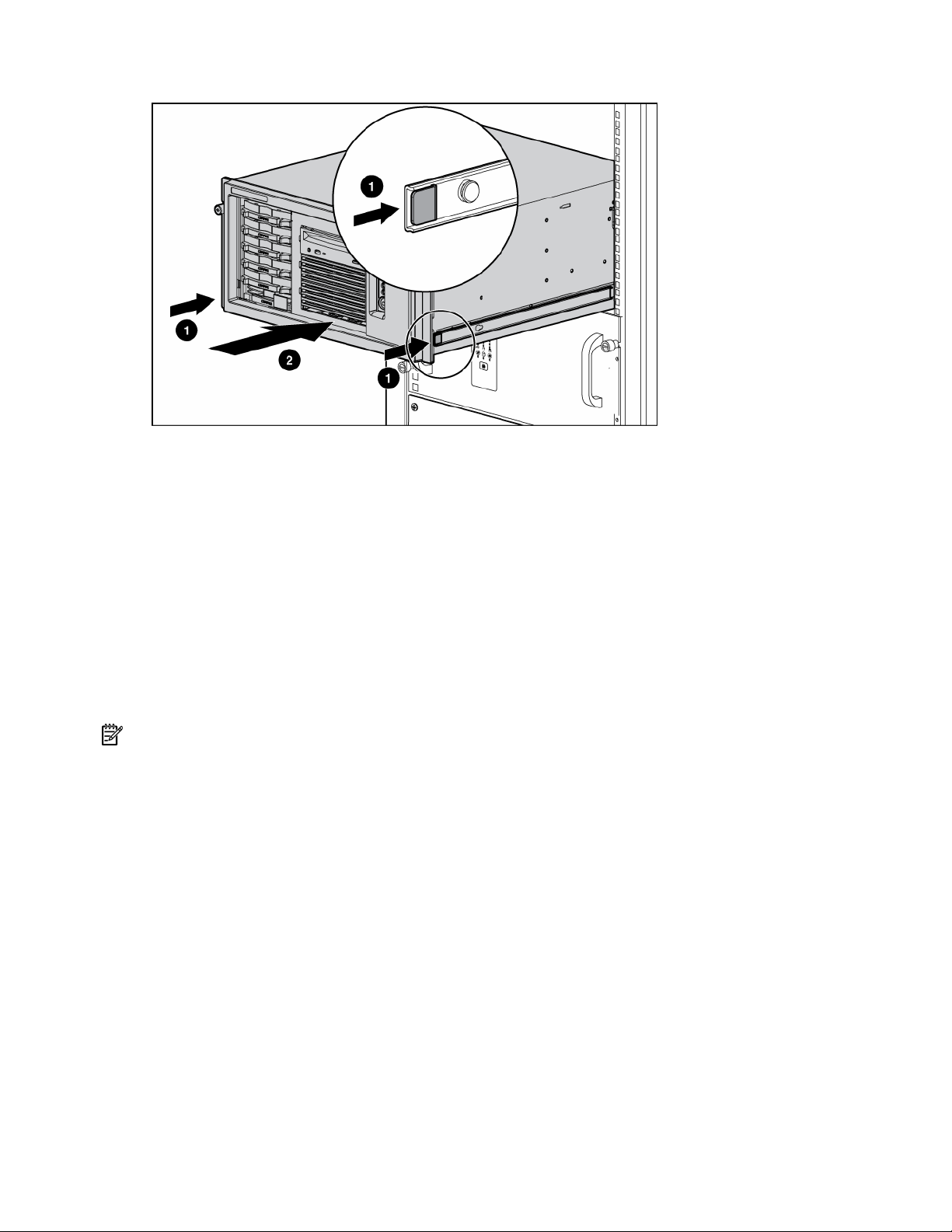
a.
Press the server rail-release latches and slide the server fully into rack.
b. Secure the server by tightening the thumbscrews.
Removing the server from the rack
To remove the server from an HP, telco, or third-party rack:
1. Power down the server (on page 16).
2. Loosen the front panel thumbscrews that secure the server faceplate to the front of the rack.
3. Disconnect the cabling and remove the server from the rack. Reverse the server installation steps in
the documentation that ships with the rack-mounting option.
4. Place the server on a sturdy, level surface.
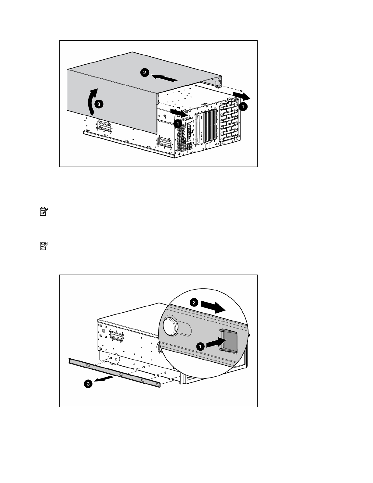
Feet
NOTE: This procedure applies to tower servers only.
To remove the component:
1. Place the server on its side.
Removal and replacement procedures 17
Page 18
2.
Remove the feet.
To replace the component, slide it back onto the locking slot. Be sure that the foot snaps securely into the
holder. Repeat with the remaining feet, as necessary.
Removal and replacement procedures 18
Page 19
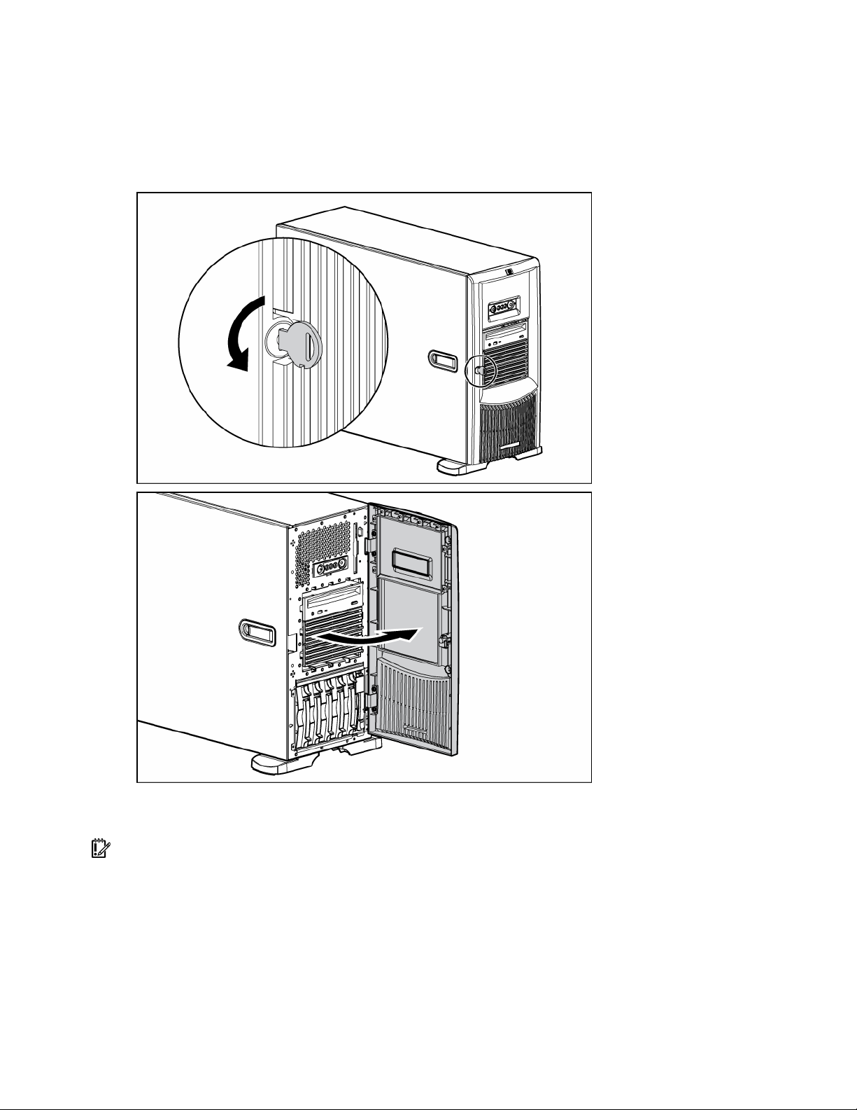
Front bezel
Tower servers have a removable front bezel that must be unlocked and opened before accessing the hard
drive cage, diskette drive, and before removing the access panel.
To unlock the front bezel, use the key provided with the server to unlock the bezel with a counterclockwise
turn.
To remove the component:
1. Unlock and open the front bezel ("Front bezel" on page 19) (tower servers only).
IMPORTANT: You must unlock the front bezel before removing the access panel.
Removal and replacement procedures 19
Page 20
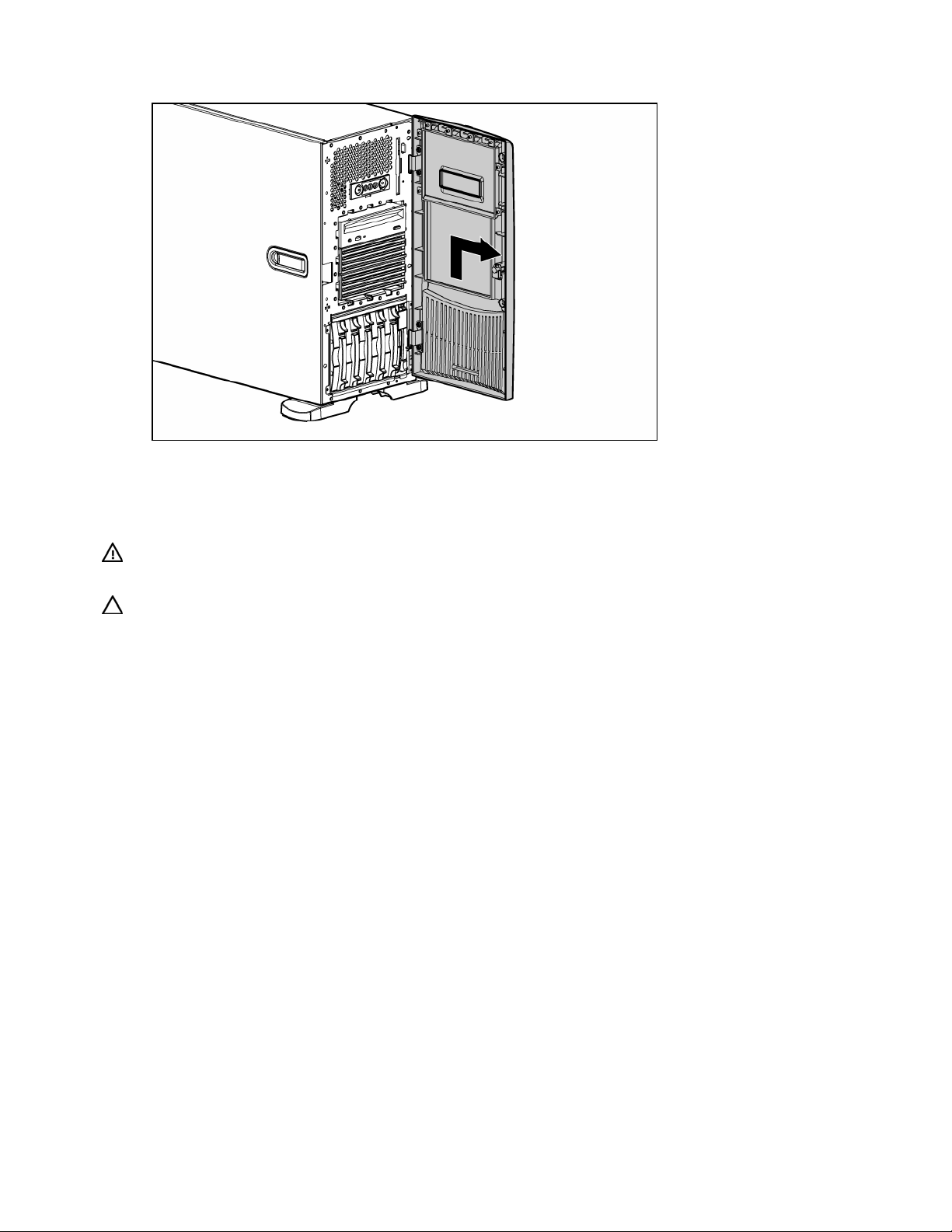
2.
Lift up the front bezel and remove it from the chassis.
To replace the component, reverse the removal procedure.
Access panel
WARNING: To reduce the risk of personal injury from hot surfaces, allow the drives and
the internal system components to cool before touching them.
CAUTION: Do not operate the server for long periods with the access panel open or removed. Operating
the server in this manner results in improper airflow and improper cooling that can lead to thermal damage.
1. Power down the server (on page 16).
2. Extend or remove the server from the rack ("Extending the server from the rack" on page 16).
3. Open the front bezel ("Front bezel" on page 19).
4. Using a Torx T-15 screwdriver, unlock the access panel locking latch.
5. Lift up on the hood latch handle and remove the access panel.
After installing hardware options, replace the access panel. Be sure that the panel is securely locked into
place before powering up the server.
Rack bezel
To remove the component:
1. Remove the access panel ("Access panel" on page 20).
2. Extend or remove the server from the rack ("Extending the server from the rack" on page 16).
Removal and replacement procedures 20
Page 21

3.
Loosen the two thumbscrews that secure the rack bezel to the chassis.
4. Remove the rack bezel.
To replace the component, reverse the removal procedure.
Tower hood cover
To remove the component:
1. Unlock and open the front bezel ("Front bezel" on page 19) (tower servers only).
2. Remove the rack bezel (rack servers only) ("Rack bezel" on page 20).
3. Use the Torx T-15 tool to remove the two front panel screws.
Removal and replacement procedures 21
Page 22
4.
Remove the tower hood cover.
To replace the component, reverse the removal procedure.
Rack rails
NOTE: This procedure applies to rack servers only.
To remove the component:
1. Use the Torx T-15 screwdriver to push in the release key.
NOTE: The T-15 Torx screwdriver is clipped to the rear panel of the server.
2. Press the rail against the side of the chassis and slide it to the front of the server to release the rails.
3. Align the four keyholes above the four spools on the side of the chassis and remove the rail.
4. Repeat steps 1 through 3 to remove the other rail.
To replace the component, reverse the removal procedure.
Removal and replacement procedures 22
Page 23
Power supply blank
WARNING: To reduce the risk of electric shock, do not disassemble the power supply or
attempt to repair it. Replace it only with the specified spare part.
CAUTION: Do not attempt to remove and replace a power supply as a hot-plug procedure unless both
bays are populated with power supplies.
To remove the component:
1. Remove the two screws with the T-15 Torx screwdriver.
NOTE: The T-15 Torx screwdriver is clipped to the rear panel of the server.
2. Remove the power supply blank.
To replace the component, reverse the removal procedure.
Hot-plug power supply
WARNING: To reduce the risk of electric shock, do not disassemble the power supply or
attempt to repair it. Replace it only with the specified spare part.
CAUTION: Do not attempt to remove and replace a power supply as a hot-plug procedure unless both
bays are populated with power supplies.
To remove the component:
1. Remove the power cord from the unit to be removed.
2. Use the Torx T-15 screwdriver to remove the shipping screw securing the handle.
NOTE: The T-15 Torx screwdriver is clipped to the rear panel of the server.
Removal and replacement procedures 23
Page 24
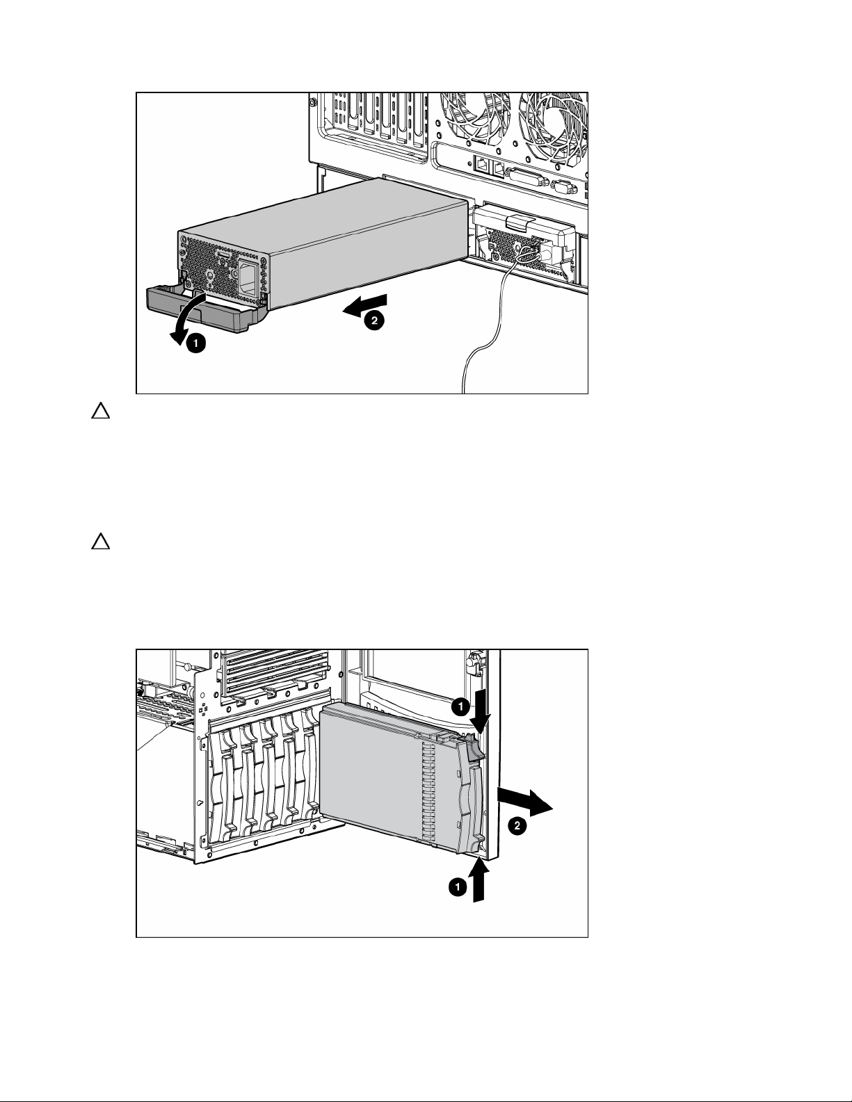
3.
Remove the power supply.
CAUTION: To prevent improper cooling and thermal damage, do not operate the server unless all bays
are populated with either a component or a blank.
To replace the component, reverse the removal procedure.
Hard drive blank (SCSI)
CAUTION: To prevent improper cooling and thermal damage, do not operate the server unless all bays
are populated with either a component or a blank.
To remove the component:
1. Unlock and open the front bezel ("Front bezel" on page 19) (tower servers only).
2. Remove the blank.
To replace the component, reverse the removal procedure.
Removal and replacement procedures 24
Page 25
Hard drives (SCSI)
CAUTION: To prevent improper cooling and thermal damage, do not operate the server unless all bays
are populated with either a component or a blank.
1. Unlock and open the front bezel ("Front bezel" on page 19) (tower servers only).
2. Determine the status of the hard drive from the hot-plug hard drive LEDs ("Hot-plug SCSI hard drive
LEDs" on page 72, "SATA or SAS hard drive LEDs" on page 73).
3. Back up all server data on the hard drive.
4. Remove the hard drive.
To replace the component, reverse the removal procedure.
Hard drive cage (SCSI)
1. Power down the server (on page 16).
2. Unlock and open the front bezel ("Front bezel" on page 19) (tower servers only).
3. Remove the rack bezel (rack servers only) ("Rack bezel" on page 20).
4. Extend or remove the server from the rack ("Extending the server from the rack" on page 16).
5. Remove the access panel ("Access panel" on page 20).
6. Remove all hard drive blanks ("Hard drive blank (SCSI)" on page 24).
7. Remove all hot-plug SCSI hard drives ("Hard drives (SCSI)" on page 25).
8. If using the duplex SCSI board option, remove the duplex SCSI board (on page 45).
9. Disconnect the point-to-point SCSI cable from the SCSI hard drive backplane.
Removal and replacement procedures 25
Page 26
10.
Disconnect the power cable from the SCSI hard drive backplane.
11. Remove the four (4) screws that secure the hard drive cage into the chassis.
12. Remove the hard drive cage.
To replace the component, reverse the removal procedure.
CAUTION: When routing cables, always be sure that the cables are not in a position where they can be
pinched or crimped.
Hard drive blank (SAS)
CAUTION: To prevent improper cooling and thermal damage, do not operate the server unless all bays
are populated with either a component or a blank.
To remove the component:
1. Unlock and open the front bezel ("Front bezel" on page 19) (tower servers only).
Removal and replacement procedures 26
Page 27

2.
Remove the blank.
To replace the component, reverse the removal procedure.
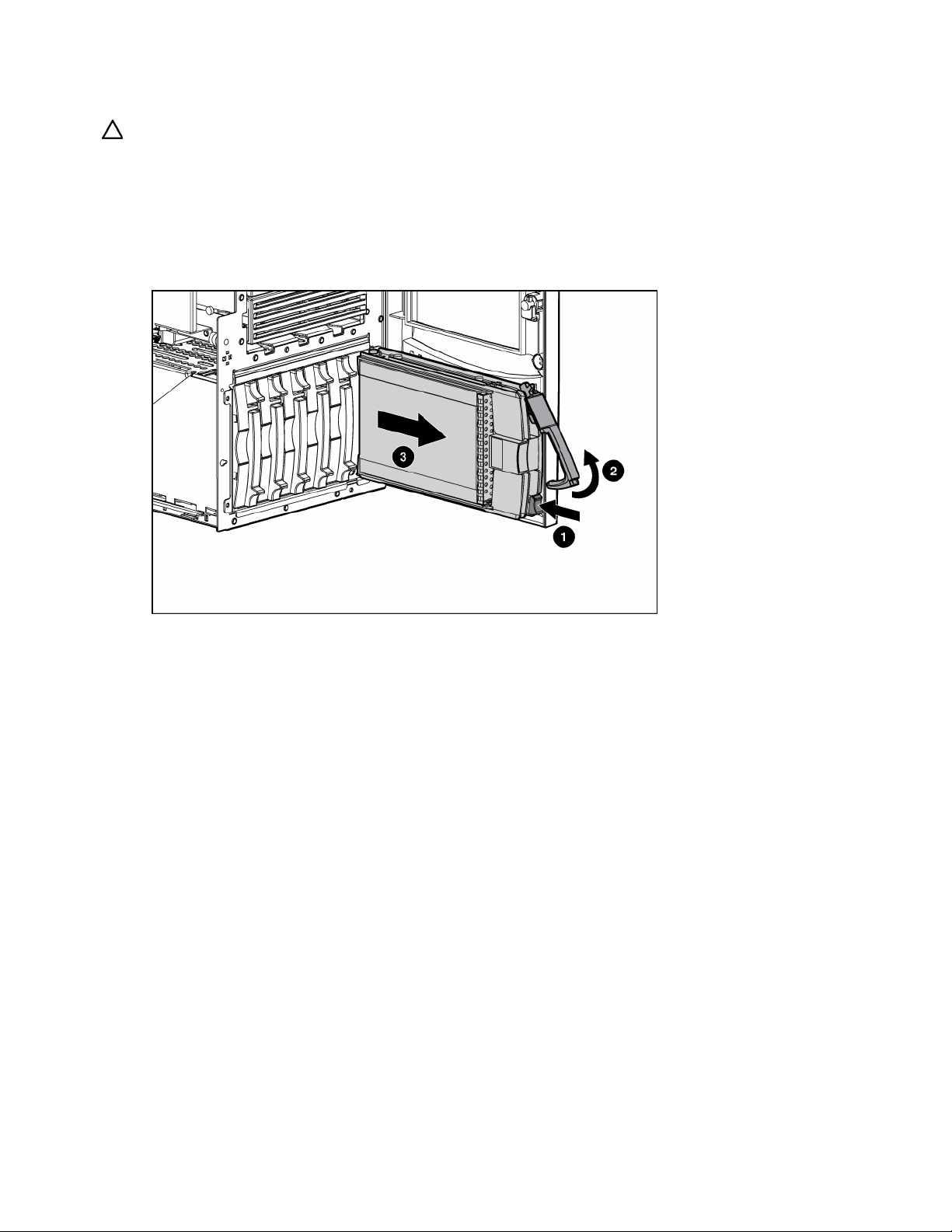
Hard drives (SAS)
CAUTION: To prevent improper cooling and thermal damage, do not operate the server unless all bays
are populated with either a component or a blank.
1. Unlock and open the front bezel ("Front bezel" on page 19) (tower servers only).
2. Determine the status of the hard drive from the hot-plug hard drive LEDs ("Hot-plug SCSI hard drive
LEDs" on page 72, "SATA or SAS hard drive LEDs" on page 73).
3. Back up all server data on the hard drive.
4. Remove the hard drive.
To replace the component, reverse the removal procedure.
Removal and replacement procedures 27
Page 28

Hard drive cage (SAS)
1. Power down the server (on page 16).
2. Unlock and open the front bezel ("Front bezel" on page 19) (tower servers only).
3. Remove the rack bezel (rack servers only) ("Rack bezel" on page 20).
4. Extend or remove the server from the rack ("Extending the server from the rack" on page 16).
5. Remove the access panel ("Access panel" on page 20).
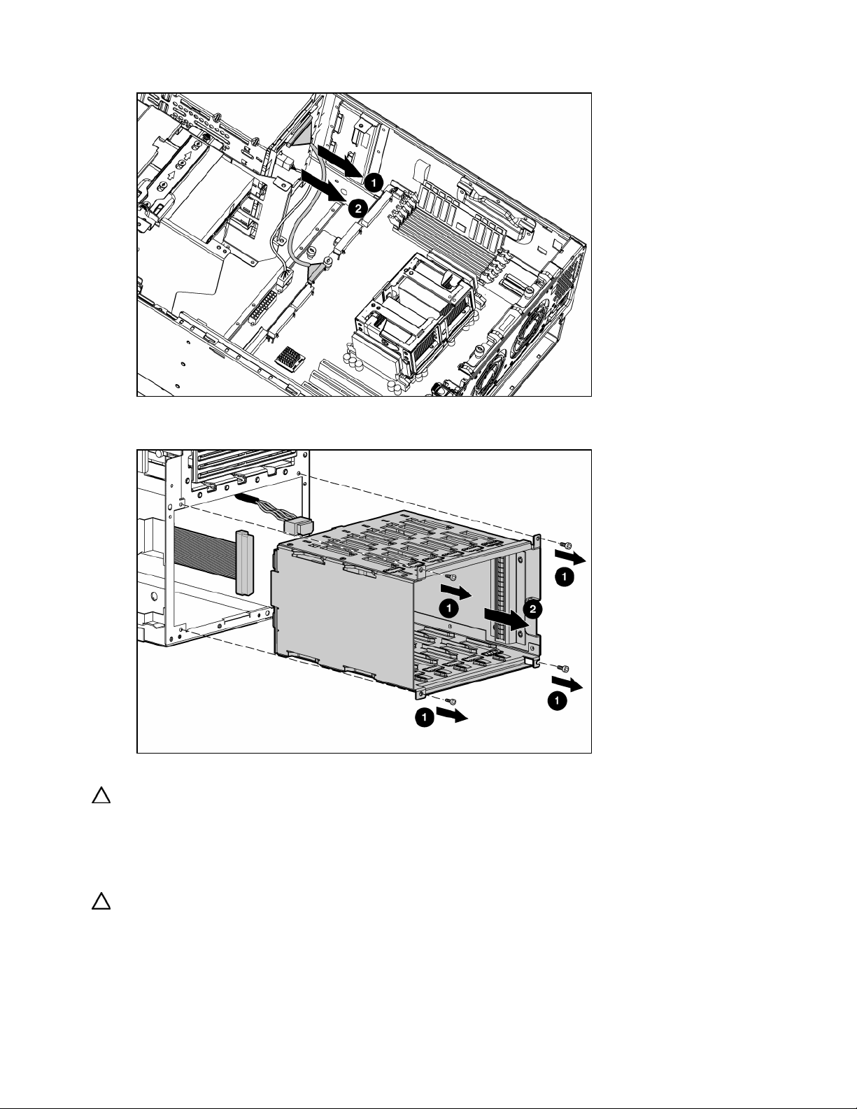
6. Disconnect the power cable from the SAS backplane.
NOTE: The center wall is removed for illustration purposes only.
7. Disconnect the SAS-SATA cables from the SAS backplane.
Removal and replacement procedures 28
Page 29

8.
Unscrew and remove the four screws that secure the drive cage to the chassis and remove the SAS
cage.
To replace the component, reverse the removal procedure.
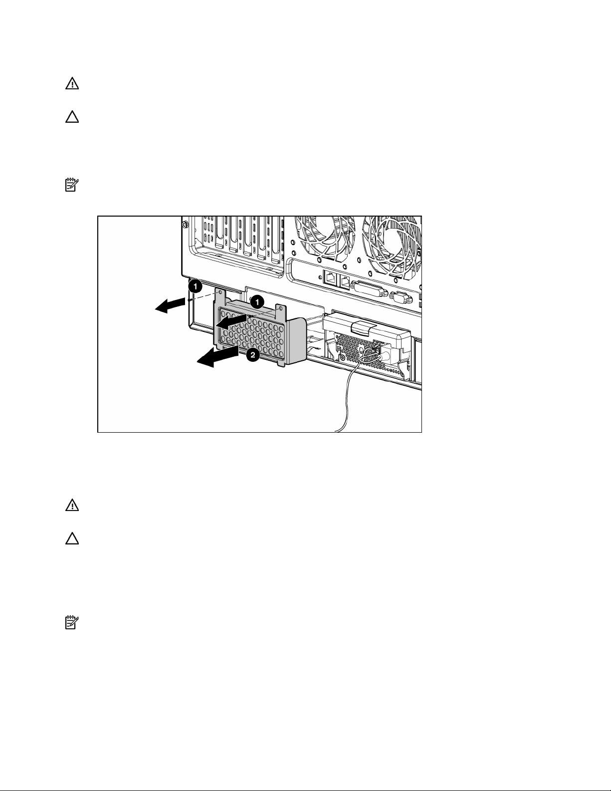
System fans
The server supports redundant hot-plug fans to provide proper airflow to the system if a primary fan fails.
In the standard configuration, three fans cool the server: fans 1, 3, and 5.
For the redundant configuration, fans 2, 4, and 6 are added to back up the primary fans. This
configuration allows the server to continue operation in non-redundant mode, if a fan failure occurs.
For fan locations, refer to "Identifying hot-plug fans ("Identifying redundant hot-plug fans" on page 73)."
All fans are identical. This procedure can be used for any of the six fan positions.
To remove the component:
1. Unlock and open the front bezel ("Front bezel" on page 19) (tower servers only).
2. Extend or remove the server from the rack ("Extending the server from the rack" on page 16).
3. Remove the access panel ("Access panel" on page 20).
Removal and replacement procedures 29
Page 30

4.
Remove the fan.
To replace the component, reverse the removal procedure.
Redundant hot-plug fan cage
For full redundancy, always install all three fans included in the redundant hot-plug fan option kit.
To remove the component:
1. Power down the server (on page 16).
2. Unlock and open the front bezel ("Front bezel" on page 19) (tower servers only).
3. Extend or remove the server from the rack ("Extending the server from the rack" on page 16).
4. Remove the access panel ("Access panel" on page 20).
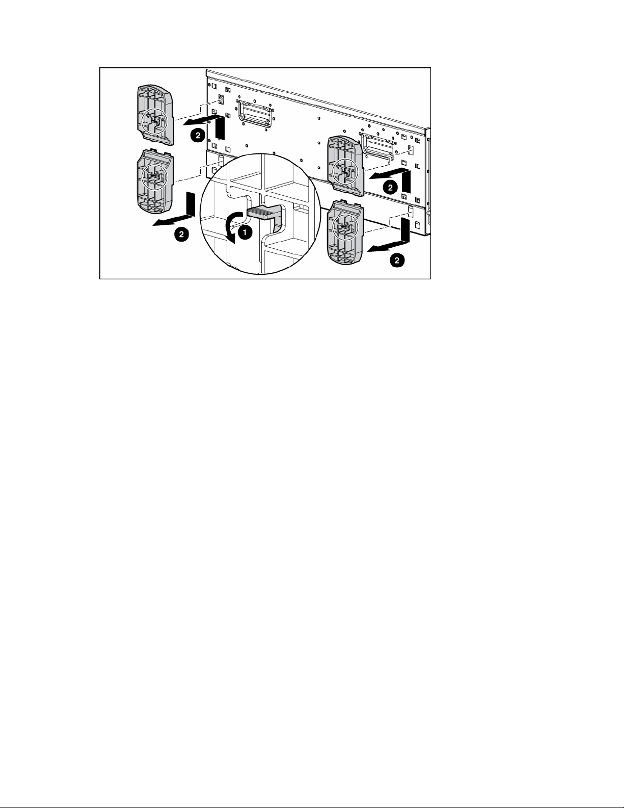
5. Remove the fans from the redundant fan cage.
6. Remove the redundant fan cage retaining bracket from the chassis.
Removal and replacement procedures 30
Page 31

IMPORTANT: Do not discard the fan cage retaining bracket. The bracket is required for proper fan
operation.
7. Slide the redundant fan cage out of the chassis.
Removal and replacement procedures 31
Page 32

8.
Reinstall the redundant fan cage retaining bracket.
To replace the component, reverse the removal procedure.
Expansion slot cover
1. Power down the server (on page 16).
2. Unlock and open the front bezel ("Front bezel" on page 19) (tower servers only).
3. Extend or remove the server from the rack ("Extending the server from the rack" on page 16).
4. Remove the access panel ("Access panel" on page 20).
5. Unlatch the slot release lever.
6. Remove the expansion slot cover.
CAUTION: To prevent improper cooling and thermal damage, do not operate the server unless all PCI slots
have either an expansion slot cover or an expansion board installed.
To replace the component, reverse the removal procedure.
Removal and replacement procedures 32
Page 33

Slot release lever
To remove the component:
1. Power down the server (on page 16).
2. Unlock and open the front bezel ("Front bezel" on page 19) (tower servers only).
3. Extend or remove the server from the rack ("Extending the server from the rack" on page 16).
4. Remove the access panel ("Access panel" on page 20).
5. Unlatch the slot release lever.
6. Remove the expansion slot cover.
7. Remove any expansion board installed in the assembly ("Expansion board" on page 33).
8. From behind the chassis, push up on the lever locking tab.
9. Pull the release lever forward to disengage the rear tabs from the server wall.
10. Remove the slot release lever from the chassis.
To replace the component, reverse the removal procedure.
IMPORTANT: Be sure that the lever locking tab is locked into place. If the lever is not locked, it will not
retain the expansion boards properly.
Expansion board
The server supports PCI-X and PCI Express expansion boards.
Slot
1 PCI-X 64-bit, 3.3-volt 100-MHz
2 PCI-X 64-bit, 3.3-volt 100-MHz
3 PCI-X 64-bit, 3.3-volt 100-MHz
4 PCI-X 64-bit, 3.3-volt 100-MHz
5 PCI Express * x8 x4
6 PCI Express * x8 x4
Expansion
card type
Connector Capable speed
Removal and replacement procedures 33
Page 34

* x8 PCI Express cards are supported, but will run at x4 speeds.
CAUTION: To prevent damage to the server or expansion boards, power down the server and remove all
AC power cords before removing or installing the expansion boards.
To remove the component:
1. Power down the server (on page 16).
2. Unlock and open the front bezel ("Front bezel" on page 19) (tower servers only).
3. Extend or remove the server from the rack ("Extending the server from the rack" on page 16).
4. Remove the access panel ("Access panel" on page 20).
5. Unlatch the slot release lever.
6. Disconnect any cables attached to the expansion board.
7. Release the retaining clip.
8. Press the slot release lever and swing the slot release lever upward.
9. Lift the expansion board out of the server.
CAUTION: Make a note of board locations. Be sure to install replacements in the same slots.
To replace the component, reverse the removal procedure.
Processor air baffle
To remove the component:
1. Power down the server (on page 16).
2. Unlock and open the front bezel ("Front bezel" on page 19) (tower servers only).
3. Extend or remove the server from the rack ("Extending the server from the rack" on page 16).
4. Remove the access panel ("Access panel" on page 20).
5. Loosen the two thumbscrews that secure the air baffle to the center wall.
Removal and replacement procedures 34
Page 35

6.
Lift the air baffle up and out of the server.
To replace the component, reverse the removal procedure.
Center wall
To remove the component:
1. Power down the server (on page 16).
2. Unlock and open the front bezel ("Front bezel" on page 19) (tower servers only).
3. Extend or remove the server from the rack ("Extending the server from the rack" on page 16).
4. Remove the access panel ("Access panel" on page 20).
5. Remove all expansion boards ("Expansion board" on page 33).
6. Loosen the four thumbscrews that secure the center wall to the chassis.
7. Lift the wall up enough to reach the fan cable.
Removal and replacement procedures 35
Page 36

8.
Disconnect the fan cable from the system board.
9. Lift the center wall away from the chassis.
To replace the component, reverse the removal procedure.
CD-ROM drive
To remove the component:
1. Power down the server (on page 16).
2. Unlock and open the front bezel ("Front bezel" on page 19) (tower servers only).
3. Extend or remove the server from the rack ("Extending the server from the rack" on page 16).
4. Remove the access panel ("Access panel" on page 20).
5. Slide the media latch to release the drives while pushing the CD-ROM drive from the inside of the
chassis slightly out of the bay.
• In tower configurations, use the media latch on the side of the removable media cage.
• In rack configurations, use the media latch on the top of the removable media cage.
Removal and replacement procedures 36
Page 37

CAUTION: To prevent improper cooling and thermal damage, do not operate the server unless all bays
are populated with either a component or a blank.
6. Disconnect the IDE cable from the CD-ROM drive.
7. Disconnect the power cable from the CD-ROM drive.
8. Remove the CD-ROM drive from the chassis.
To replace the component, reverse the removal procedure.
CAUTION: When routing cables, always be sure that the cables are not in a position where they can be
pinched or crimped.
Power button/LED assembly
To remove the component:
1. Power down the server (on page 16).
2. Unlock and open the front bezel ("Front bezel" on page 19) (tower servers only).
3. Extend or remove the server from the rack ("Extending the server from the rack" on page 16).
4. Remove the access panel ("Access panel" on page 20).
5. Remove all expansion boards ("Expansion board" on page 33).
6. Remove the center wall ("Center wall" on page 35).
7. Disconnect the power button/LED assembly cable from the system board and power supply
backplane.
Removal and replacement procedures 37
Page 38

8.
Squeeze the two tabs securing the assembly from the inside, and slide the power button/LED
assembly through the front of the server.
9. Remove the assembly from the chassis.
To replace the component, reverse the removal procedure.
Diskette drive
To remove the component:
1. Power down the server (on page 16).
2. Unlock and open the front bezel ("Front bezel" on page 19) (tower servers only).
3. Extend or remove the server from the rack ("Extending the server from the rack" on page 16).
4. Remove the access panel ("Access panel" on page 20).
5. Remove all expansion boards ("Expansion board" on page 33).
6. Remove the center wall ("Center wall" on page 35).
7. Remove the power button/LED assembly ("Power button/LED assembly" on page 37).
Removal and replacement procedures 38
Page 39

8.
Disconnect the diskette drive cable and power cable from the diskette drive.
9. Loosen the thumbscrews that secure the retaining bracket to the diskette chassis.
10. Pull the diskette retaining bracket forward to disengage the tabs and lift the bracket from the chassis.
11. Pull the diskette drive backward about 1 cm (0.4 in) and lift it up to clear the base.
12. Remove the diskette drive from the chassis.
To replace the component, reverse the removal procedure.
Processor assembly
CAUTION: Be sure that you have the current version of the system ROM. Failure to flash the ROM with the
correct version before installing or replacing the processor causes system failure. For the most current version
of the ROM, go to the HP website (http://www.hp.com/support
CAUTION: The processor, heatsink, and retaining clip comprise a single assembly. Separating the
processor from the heatsink causes thermal instability and damage to the server.
).
Removal and replacement procedures 39
Page 40

CAUTION: Do not mix the 2-MB L2 Cache processors with the 1-MB L2 Cache processors.
To remove the component:
1. Power down the server (on page 16).
2. Unlock and open the front bezel ("Front bezel" on page 19) (tower servers only).
3. Extend or remove the server from the rack ("Extending the server from the rack" on page 16).
4. Remove the access panel ("Access panel" on page 20).
5. Remove the processor air baffle ("Processor air baffle" on page 34).
6. Open the processor cage.
7. Lift the processor retaining bracket lever to release the processor retaining bracket.
8. Lift the processor retaining bracket.
9. Release the processor locking lever.
10. Remove the processor/heatsink assembly.
To replace the component:
1. Open the processor retaining bracket.
2. Install the processor/heatsink assembly into the available processor socket:
Removal and replacement procedures 40
Page 41

a.
Determine the correct processor orientation by observing the three guide pins on the processor
retaining bracket and the three corresponding guide holes on the processor/heatsink assembly.
b. Be sure the processor locking lever is open.
c. Insert the processor/heatsink assembly into the processor socket.
d. Close the processor locking lever.
IMPORTANT: If the processor locking lever is not secured, the processor retaining bracket will not close
properly.
Removal and replacement procedures 41
Page 42

3.
Lower the processor retaining bracket into position over the processor.
4. Press the processor retaining bracket lever down to secure the processor retaining bracket.
CAUTION: To prevent possible server malfunction or damage to the equipment, be sure to completely close
the processor locking lever.
NOTE: When replacing a failed processor, run the RBSU after replacing the new processor to mark the
failed processor as repaired. Refer to the HP ProLiant ML370 Generation 4 Server Reference and
Troubleshooting Guide or the HP ROM-Based Setup Utility User Guide for more detailed information on
RBSU.
Processor power module (PPM)
To remove the component:
1. Power down the server (on page 16).
2. Unlock and open the front bezel ("Front bezel" on page 19) (tower servers only).
3. Extend or remove the server from the rack ("Extending the server from the rack" on page 16).
4. Remove the access panel ("Access panel" on page 20).
5. Remove the processor air baffle ("Processor air baffle" on page 34).
Removal and replacement procedures 42
Page 43

6.
Remove the PPM.
NOTE: The appearance of compatible PPMs may vary.
CAUTION: Only install a PPM if the processor is installed. Both the PPM and the processor must be
installed together, otherwise the system does not boot.
IMPORTANT: PPMs do not seat if turned the wrong way.
To replace the component, reverse the removal procedure.
DIMM
To remove the component:
1. Power down the server (on page 16).
2. Unlock and open the front bezel ("Front bezel" on page 19) (tower servers only).
3. Extend or remove the server from the rack ("Extending the server from the rack" on page 16).
4. Remove the access panel ("Access panel" on page 20).
5. Remove the processor air baffle ("Processor air baffle" on page 34).
Removal and replacement procedures 43
Page 44

6.
Remove the DIMM.
IMPORTANT: DIMMs do not seat fully if turned the wrong way.
For DIMM configuration information, refer to the HP ProLiant ML370 Generation 4 Server Reference and
Troubleshooting Guide.
To replace the component, reverse the removal procedure.
SCSI backplane
To remove the component:
1. Power down the server (on page 16).
2. Unlock and open the front bezel ("Front bezel" on page 19) (tower servers only).
3. Remove the rack bezel (rack servers only) ("Rack bezel" on page 20).
4. Extend or remove the server from the rack ("Extending the server from the rack" on page 16).
5. Remove the access panel ("Access panel" on page 20).
6. Remove the hard drive cage ("Hard drive cage (SCSI)" on page 25).
Removal and replacement procedures 44
Page 45

7.
Remove the SCSI backplane.
To replace the component, reverse the removal procedure.
Duplex SCSI board
1. Power down the server (on page 16).
2. Unlock and open the front bezel ("Front bezel" on page 19) (tower servers only).
3. Remove the rack bezel (rack servers only) ("Rack bezel" on page 20).
4. Extend or remove the server from the rack ("Extending the server from the rack" on page 16).
5. Remove the access panel ("Access panel" on page 20).
6. Remove the hard drive cage ("Hard drive cage (SCSI)" on page 25).
7. Remove the duplex SCSI board from the SCSI backplane.
If replacing the SCSI backplane and drive cage, refer to SCSI backplane.
To replace the component, reverse the removal procedure.
Removal and replacement procedures 45
Page 46

VHDCI or HD68 SCSI cable option
The VHDCI or HD68 SCSI Cable connects the server to external SCSI-based storage or backup devices.
The cabling option kit must be used for internal ports to be used externally.
IMPORTANT: To install the external SCSI option, an internal SCSI port must be dedicated for external use
only.
In addition to the VHDCI or HD68 SCSI cable, you will also need:
• T-15 Torx screwdriver
• Flathead screwdriver
NOTE: A PCI blank included with the optional Internal-to-External SCSI Kit enables the optional HD68 SCSI
cable to connect through a PCI-X or PCI Express expansion slot. Refer to the Internal-to-External SCSI Kit
installation instructions for details.
To prepare the server before installing or removing options:
1. Power down the server (on page 16).
2. Unlock and open the front bezel ("Front bezel" on page 19) (tower servers only).
3. Extend or remove the server from the rack ("Extending the server from the rack" on page 16).
4. Remove the access panel ("Access panel" on page 20).
WARNING: To reduce the risk of electric shock or damage to the equipment, disconnect
power from the server by unplugging all power cords from the electrical outlets.
CAUTION: Failure to correctly power down the server could result in damage to equipment or loss of
information.
5. Using a T-15 Torx screwdriver, remove a SCSI knockout located on the rear of the chassis and retain
the screw.
6. Remove any brackets on the VHDCI cable, if necessary.
7. Connect the preassembled cable bracket assembly through the external SCSI knockout on the rear of
the chassis, and secure the cable using the screw retained in step 5.
8. Connect the other end of the VHDCI SCSI cable to an available SCSI port or a PCI card.
NOTE: Refer to the documentation that shipped with the external storage device for more information.
Removal and replacement procedures 46
Page 47

To replace the component, reverse the removal procedure.
Power supply backplane
To remove the component:
1. Power down the server (on page 16).
2. Unlock and open the front bezel ("Front bezel" on page 19) (tower servers only).
3. Remove all hot-plug power supplies ("Hot-plug power supply" on page 23).
4. Extend or remove the server from the rack ("Extending the server from the rack" on page 16).
5. Remove the access panel ("Access panel" on page 20).
6. Remove all expansion boards ("Expansion board" on page 33).
7. Remove the center wall ("Center wall" on page 35).
8. Disconnect the signal cable from the power supply backplane.
9. Disconnect all cables from the system board, as necessary, in order to access the power supply
backplane.
Removal and replacement procedures 47
Page 48

10.
Remove the power supply backplane.
To replace the component, reverse the removal procedure.
IMPORTANT: Be sure to align the two retaining guides on the chassis with the holes on the power supply
backplane when replacing it.
System board
IMPORTANT: If replacing the system board or clearing NVRAM, you must re-enter the server serial number
through RBSU ("Re-entering the server serial number and product ID" on page 50).
To remove the component:
1. Power down the server (on page 16).
2. Unlock and open the front bezel ("Front bezel" on page 19) (tower servers only).
3. Extend or remove the server from the rack ("Extending the server from the rack" on page 16).
4. Remove the access panel ("Access panel" on page 20).
5. Remove the redundant fan cage (if installed) ("Redundant hot-plug fan cage" on page 30).
6. Remove all expansion boards ("Expansion board" on page 33).
7. Remove the center wall ("Center wall" on page 35).
8. Disconnect all cables.
9. Loosen the two thumbscrews securing the system board to the chassis.
10. Slide the system board toward the front of the chassis to release it from the six retaining guides.
Removal and replacement procedures 48
Page 49

11.
Lift the system board out of the chassis and tilt it to one side to clear the cable guide.
To replace the component, reverse the removal procedure.
Battery
If the server no longer automatically displays the correct date and time, you may need to replace the
battery that provides power to the real-time clock. Under normal use, battery life is 5 to 10 years.
WARNING: The computer contains an internal lithium manganese dioxide, a vanadium
pentoxide, or an alkaline battery pack. A risk of fire and burns exists if the battery pack
is not properly handled. To reduce the risk of personal injury:
• Do not attempt to recharge the battery.
• Do not expose the battery to temperatures higher than 60°C (140°F).
• Do not disassemble, crush, puncture, short external contacts, or dispose of in fire or
water.
• Replace only with the spare designated for this product.
To remove the component:
1. Power down the server (on page 16).
2. Unlock and open the front bezel ("Front bezel" on page 19) (tower servers only).
3. Extend or remove the server from the rack ("Extending the server from the rack" on page 16).
4. Remove the access panel ("Access panel" on page 20).
Removal and replacement procedures 49
Page 50

5.
Remove the battery.
To replace the component, reverse the removal procedure.
Run RBSU to configure the system after replacing the battery. Refer to the HP ROM-Based Setup Utility
User Guide for more detailed information.
Re-entering the server serial number and product ID
After you replace the system board, you must re-enter the server serial number and the product ID.
1. During the server startup sequence, press the F9 key to access RBSU.
2. Select the System Options menu.
3. Select Serial Number. The following warning is displayed:
WARNING! WARNING! WARNING! The serial number is loaded into the system
during the manufacturing process and should NOT be modified. This option
should only be used by qualified service personnel. This value should
always match the serial number sticker located on the chassis.
4. Press the Enter key to clear the warning.
5. Enter the serial number and press the Enter key.
6. Select Product ID.
7. Enter the product ID and press the Enter key.
8. Press the Esc key to close the menu.
9. Press the Esc key to exit RBSU.
10. Press the F10 key to confirm exiting RBSU. The server will automatically reboot.
Removal and replacement procedures 50
Page 51

Server cabling
In this section
Cabling overview................................................................................................................................... 51
Hot-plug SCSI cabling............................................................................................................................. 51
SAS cabling .......................................................................................................................................... 55
CD-ROM drive cabling ........................................................................................................................... 57
Diskette drive cabling ............................................................................................................................. 57
External storage cabling.......................................................................................................................... 58
Storage device cabling guidelines............................................................................................................ 58
RILOE II cabling ..................................................................................................................................... 58
Cabling overview
This section provides guidelines that help you make informed decisions about cabling the server and
hardware options to optimize performance.
For information on cabling peripheral components, refer to the white paper on high-density deployment at
the HP website (http://www.hp.com/products/servers/platforms
CAUTION: When routing cables, always be sure that the cables are not in a position where they can be
pinched or crimped.
).
Hot-plug SCSI cabling
Integrated simplex SCSI cabling (on page 51)
Integrated duplex SCSI cabling (on page 52)
Integrated SCSI cabling with optional internal two-bay hot-plug SCSI drive cage (on page 53)
Array controller simplex SCSI cabling (on page 54)
Array controller duplex SCSI cabling (on page 54)
Array controller duplex SCSI cabling with optional internal two-bay hot-plug SCSI drive cage (on page
Integrated simplex SCSI cabling
55)
In the integrated simplex cabling configuration, which is the standard shipping configuration, the
integrated SCSI controller controls up to six hard drives through one SCSI port.
Server cabling 51
Page 52

NOTE: The cables shown ship standard with the server.
Item Component description SCSI IDs managed
1 SCSI cable (SCSI 1) 0, 1, 2, 3, 4, 5
2 simplex SCSI cable N/A
IMPORTANT: After changing any SCSI configuration, be sure the proper boot controller order is set in
RBSU.
Integrated duplex SCSI cabling
In the optional integrated duplex cabling configuration, the integrated controller controls up to six hard
drives through two SCSI ports: one with up to two drives, and the other with up to four drives.
NOTE: The Duplex SCSI Backplane Option Kit is required for duplex cabling configurations. The kit
contains a duplex SCSI cable and a duplex SCSI board.
Item Component description SCSI IDs managed
1 SCSI cable (SCSI 1) 0, 1, 2, 3
Server cabling 52
Page 53

Item Component description SCSI IDs managed
2 SCSI cable (SCSI 2) * 4, 5
3 Duplex SCSI board N/A
* One SCSI cable is provided with the server.
Integrated SCSI cabling with optional internal two-bay hot-plug SCSI drive cage
When cabling an optional internal two-bay hot-plug SCSI drive cage with the integrated drive cage, the
embedded integrated SCSI controller controls up to two hard drives on one SCSI bus and up to six hard
drives on the second SCSI bus.
Item Component description SCSI IDs managed
1 SCSI cable ** 0, 1, 2, 3, 4, 5
2 SCSI cable * 0, 1
* One SCSI cable is provided with the server.
** One SCSI cable is provided with the internal two-bay hot-plug SCSI drive cage.
Server cabling 53
Page 54

Array controller simplex SCSI cabling
In the array controller simplex SCSI cabling configuration, an optional PCI array controller controls up to
six hard drives through one SCSI bus.
Component description SCSI IDs managed
SCSI cable * 0, 1, 2, 3, 4, 5
* One SCSI cable is provided with the server.
Array controller duplex SCSI cabling
NOTE: The Duplex SCSI Backplane Option Kit is required for duplex cabling configurations. The kit
contains a duplex SCSI cable and a duplex SCSI board.
In the array controller duplex SCSI cabling configuration, the optional PCI array controller controls up to
four hard drives on one SCSI bus and two hard drives on the other SCSI bus.
Item Component description SCSI IDs managed
1 SCSI cable 0, 1, 2, 3
Server cabling 54
Page 55

Item Component description SCSI IDs managed
2 SCSI cable * 4, 5
* One SCSI cable is provided with the server.
Array controller duplex SCSI cabling with optional internal two-bay hot-plug SCSI
drive cage
When cabling an optional internal two-bay hot-plug SCSI drive cage with the integrated drive cage, the
optional PCI array controller controls up to two hard drives on one SCSI bus and up to six hard drives on
the other SCSI bus.
Item Component description SCSI IDs managed
1 SCSI cable * 0, 1, 2, 3, 4, 5
2 SCSI cable ** 0, 1
* One SCSI cable is provided with the server.
** One SCSI cable is provided with the internal two-bay hot-plug SCSI drive cage.
SAS cabling
NOTE: The center wall is removed for illustration purposes only.
Server cabling 55
Page 56

•
Power cables
• Data cables
Server cabling 56
Page 57

CD-ROM drive cabling
Item Cable description
1 CD-ROM drive power cable
2 CD-ROM drive data cable
Diskette drive cabling
Item Cable description
1 Diskette drive power cable
2 Diskette drive data cable
Server cabling 57
Page 58

External storage cabling
With the optional cable kit, the server supports external storage devices through the Auxiliary VHDCI
SCSI connector ("VHDCI or HD68 SCSI cable option" on page 46) on the rear panel of the server.
For more information on external cabling, refer to the HP website
(http://www.hp.com/products/servers/platforms
).
Storage device cabling guidelines
CAUTION: To prevent damage to the equipment, be sure that the server is powered down, all cables are
disconnected from the back of the server, and the power cord is disconnected from the grounded (earthed)
AC outlet before installing devices.
CAUTION: To prevent damage to electrical components, properly ground the server before beginning any
installation procedure. Improper grounding can cause electrostatic discharge.
RILOE II cabling
The 30-pin Remote Insight cable ships with the RILOE II cable kit.
Server cabling 58
Page 59

IMPORTANT: Install the RILOE II board into slot 1 for ease of cabling.
Server cabling 59
Page 60

Diagnostic tools
In this section
Automatic Server Recovery...................................................................................................................... 60
HP Systems Insight Manager.................................................................................................................... 60
Integrated Management Log.................................................................................................................... 60
Lights Out Manager technology ............................................................................................................... 61
Option ROM Configuration for Arrays...................................................................................................... 61
ProLiant Essentials Rapid Deployment Pack................................................................................................ 61
HP ROM-Based Setup Utility .................................................................................................................... 62
ROMPaq utility....................................................................................................................................... 62
System Online ROM flash component utility............................................................................................... 62
SmartStart software ................................................................................................................................ 62
Automatic Server Recovery
ASR is a feature that causes the system to restart when a catastrophic operating system error occurs, such
as a blue screen, ABEND, or panic. A system fail-safe timer, the ASR timer, starts when the System
Management driver, also known as the Health Driver, is loaded. When the operating system is
functioning properly, the system periodically resets the timer. However, when the operating system fails,
the timer expires and restarts the server.
ASR increases server availability by restarting the server within a specified time after a system hang or
shutdown. At the same time, the HP SIM console notifies you by sending a message to a designated
pager number that ASR has restarted the system. You can disable ASR from the HP SIM console or
through RBSU.
HP Systems Insight Manager
HP SIM is a web-based application that allows system administrators to accomplish normal administrative
tasks from any remote location, using a web browser. HP SIM provides device management capabilities
that consolidate and integrate management data from HP and third-party devices.
IMPORTANT: You must install and use HP SIM to benefit from the Pre-Failure Warranty for processors,
SAS and SCSI hard drives, and memory modules.
For additional information, refer to the Management CD in the HP ProLiant Essentials Foundation Pack or
the HP SIM website (http://www.hp.com/go/hpsim
).
Integrated Management Log
The IML records hundreds of events and stores them in an easy-to-view form. The IML timestamps each
event with 1-minute granularity.
You can view recorded events in the IML in several ways, including the following:
• From within HP SIM ("HP Systems Insight Manager" on page 60)
Diagnostic tools 60
Page 61

•
From within Survey Utility
• From within operating system-specific IML viewers
• For NetWare: IML Viewer
• For Windows®: IML Viewer
• For Linux: IML Viewer Application
• From within the RILOE user interface
• From within HP Insight Diagnostics (on page 63)
For more information, refer to the Management CD in the HP ProLiant Essentials Foundation Pack.
Lights Out Manager technology
The RILOE subsystem is a standard component of selected ProLiant servers that provides server health and
remote server manageability. The RILOE subsystem includes an intelligent microprocessor, secure memory,
and a dedicated network interface. This design makes RILOE independent of the host server and its
operating system. The RILOE subsystem provides remote access to any authorized network client, sends
alerts, and provides other server management functions.
Using RILOE, you can:
• Remotely power up, power down, or reboot the host server.
• Send alerts from RILOE regardless of the state of the host server.
• Access advanced troubleshooting features through the RILOE interface.
• Diagnose RILOE using HP SIM through a web browser and SNMP alerting.
For more information about RILOE features, refer to the RILOE documentation on the Documentation CD or
on the HP website (http://www.hp.com/servers/lights-out).
Option ROM Configuration for Arrays
NOTE: ORCA is supported with the use of an optional HP Array Controller.
Before installing an operating system, you can use the ORCA utility to create the first logical drive, assign
RAID levels, and establish online spare configurations.
The utility provides support for the following functions:
• Configuring one or more logical drives using physical drives on one or more SCSI buses
• Viewing the current logical drive configuration
• Deleting a logical drive configuration
If you do not use the utility, ORCA will default to the standard configuration.
For more information regarding array controller configuration, refer to the controller user guide.
For more information regarding the default configurations that ORCA uses, refer to the HP ROM-Based
Setup Utility User Guide on the Documentation CD.
ProLiant Essentials Rapid Deployment Pack
The RDP is an integrated HP and Altiris solution that automates the process of deploying and provisioning
server software. Refer to the RDP website (http://www.hp.com/servers/rdp
).
Diagnostic tools 61
Page 62

HP ROM-Based Setup Utility
RBSU, an embedded configuration utility, performs a wide range of configuration activities that may
include:
• Configuring system devices and installed options
• Displaying system information
• Selecting the primary boot controller
• Configuring memory options
• Language selection
For more information on RBSU, refer to the HP ROM-Based Setup Utility User Guide on the Documentation
CD or the HP website (http://www.hp.com/servers/smartstart).
ROMPaq utility
Flash ROM enables you to upgrade the firmware (BIOS) with system or option ROMPaq utilities. To
upgrade the BIOS, insert a ROMPaq diskette into the diskette drive and boot the system.
The ROMPaq utility checks the system and provides a choice (if more than one exists) of available ROM
revisions. This procedure is the same for both system and option ROMPaq utilities.
For more information about the ROMPaq utility, refer to the HP website
(http://www.hp.com/servers/manage
).
System Online ROM flash component utility
The Online ROM Flash Component Utility enables system administrators to efficiently upgrade system or
controller ROM images across a wide range of servers and array controllers. This tool has the following
features:
• Works offline and online
• Supports Microsoft® Windows NT®, Windows® 2000, Windows Server™ 2003, Novell Netware,
and Linux operating systems
IMPORTANT: This utility supports operating systems that may not be supported by the server. For
operating systems supported by the server, refer to the HP website (http://www.hp.com/go/supportos
• Integrates with other software maintenance, deployment, and operating system tools
• Automatically checks for hardware, firmware, and operating system dependencies, and installs only
the correct ROM upgrades required by each target server
To download the tool and for more information, refer to the HP website
(http://h18000.www1.hp.com/support/files/index.html
).
SmartStart software
).
SmartStart is a collection of software that optimizes single-server setup, providing a simple and consistent
way to deploy server configuration. SmartStart has been tested on many ProLiant server products,
resulting in proven, reliable configurations.
SmartStart assists the deployment process by performing a wide range of configuration activities,
including:
• Configuring hardware using embedded configuration utilities, such as RBSU and ORCA
Diagnostic tools 62
Page 63

•
Preparing the system for installing "off-the-shelf" versions of leading operating system software
• Installing optimized server drivers, management agents, and utilities automatically with every
assisted installation
• Testing server hardware using the Insight Diagnostics Utility ("HP Insight Diagnostics" on page 63)
• Installing software drivers directly from the CD. With systems that have internet connection, the
SmartStart Autorun Menu provides access to a complete list of ProLiant system software.
• Enabling access to the Array Configuration Utility, Array Diagnostic Utility, and Erase Utility
SmartStart is included in the HP ProLiant Essentials Foundation Pack. For more information about
SmartStart software, refer to the HP ProLiant Essentials Foundation Pack or the HP website
(http://www.hp.com/servers/smartstart
SmartStart Scripting Toolkit
The SmartStart Scripting Toolkit is a server deployment product that delivers an unattended automated
installation for high-volume server deployments. The SmartStart Scripting Toolkit is designed to support
ProLiant BL, ML, and DL servers. The toolkit includes a modular set of utilities and important documentation
that describes how to apply these new tools to build an automated server deployment process.
Using SmartStart technology, the Scripting Toolkit provides a flexible way to create standard server
configuration scripts. These scripts are used to automate many of the manual steps in the server
configuration process. This automated server configuration process cuts time from each server deployed,
making it possible to scale server deployments to high volumes in a rapid manner.
).
For more information, and to download the SmartStart Scripting Toolkit, refer to the HP website
(http://www.hp.com/servers/sstoolkit
HP Insight Diagnostics
HP Insight Diagnostics is a proactive server management tool, available in both offline and online
versions, that provides diagnostics and troubleshooting capabilities to assist IT administrators who verify
server installations, troubleshoot problems, and perform repair validation.
HP Insight Diagnostics Offline Edition performs various in-depth system and component testing while the
OS is not running. To run this utility, launch the SmartStart CD.
HP Insight Diagnostics Online Edition is a web-based application that captures system configuration and
other related data needed for effective server management. Available in Microsoft® Windows® and
Linux versions, the utility helps to ensure proper system operation.
For more information or to download the utility, refer to the HP website
(http://www.hp.com/servers/diags
).
).
Diagnostic tools 63
Page 64

Server component identification
In this section
Front panel components .......................................................................................................................... 64
Front panel LEDs and buttons................................................................................................................... 65
Rear panel components........................................................................................................................... 66
Rear panel LEDs and buttons ................................................................................................................... 66
System board components....................................................................................................................... 68
System board LEDs................................................................................................................................. 70
System LEDs and internal health LED combinations ..................................................................................... 71
Hot-plug SCSI hard drive LEDs ................................................................................................................. 72
SATA or SAS hard drive LEDs.................................................................................................................. 73
Identifying redundant hot-plug fans........................................................................................................... 73
Hot-plug fan LEDs................................................................................................................................... 74
Front panel components
Item Description
1 UID switch and LED
2 Internal system health LED
3 Front panel USB port
4 External system health LED
5 NIC link/activity LED
6 Power on/Standby button/LED assembly
7 Diskette drive*
Server component identification 64
Page 65

Item Description
8 Removable media bays
9 Hot-plug SCSI hard drive bays (SCSI IDs 0 through 5)
10 Optional SAS-SATA hard drive bays (1 through 8)
* Open the media door on the rack server to access the diskette drive.
Front panel LEDs and buttons
Item Description Status
1 UID switch and LED Blue = Activated
Flashing blue = System being managed remotely
Off = Deactivated
2 Internal system health LED Green = Normal (system on)
Amber = System health is degraded
Red = System health is critical
Off = Normal (system off)
3
External system health
(power supply) LED
Green = Normal (system on)
Amber = Redundant power supply failure
Red = Power supply failure. No operational power supplies.
Off = Normal (system off)
4
NIC link/activity LED
(embedded NIC only)
Green = Linked to network
Flashing green = Linked with activity on the network
Off = No network connection
5
Power on/Standby button
and LED
Amber = System has AC power and is in standby mode
Green = System has AC power and is turned on
Off = System has no AC power
Server component identification 65
Page 66

Rear panel components
Item Description Item Description
1 x4 PCI Express expansion slots 9 Auxiliary VHDCI SCSI blank
2 100-MHz PCI-X expansion slots 10 Mouse connector
3 Unit ID LED 11 Keyboard connector
4 Ethernet 10/100/1000 port 12 Serial connector B
5 iLO management port 13 Serial connector A
6 Parallel connector 14 USB connectors
7 Video connector 15 Primary hot-plug power supply
8 T-15 Torx screwdriver 16 Redundant hot-plug power supply
Rear panel LEDs and buttons
Server component identification 66
Page 67

Item Description LED color Status
1 Unit ID LED Blue On = Activated
Flashing = System remotely managed
Off = Deactivated
2
3
NIC activity LED
(Integrated NC7781)
NIC link LED
(Integrated NC7781)
Green On or flashing = Linked to network
Off = Not linked to network
Green On = Network activity
Off = No network activity
4 iLO NIC activity LED Green On or flashing = Network activity
Off = No network activity
5 iLO NIC Link LED Green On = Linked to network
Off = Not linked to network
6
Power supply LED
(redundant)
Green
On = Power turned on and power supply
functioning properly
Off = One or more of the following conditions
exists:
• AC power unavailable
• Power supply failed
• Power supply in standby mode
• Power supply exceeded current limit
7 Power supply LED (primary) Green
On = Power turned on and power supply
functioning properly
Off = One or more of the following conditions
exists:
• AC power unavailable
• Power supply failed
• Power supply in standby mode
• Power supply exceeded current limit
Server component identification 67
Page 68

System board components
Item Description Item Description
1 Redundant fan 2 connector 13 Power supply connector
2 System maintenance switch 14 SCSI port 1
3 System battery 15 PPM socket 2
4 Redundant fan 4 connector 16 PPM socket 1 (populated)
5
6
7
8
9
10
11
12
* x8 PCI Express cards are supported, but will run at x4 speeds.
** The server comes with iLO remote management capability embedded on the system board. The 30-pin remote
management connector for the RILOE II board is provided if the server environment requires an upgrade for improved
Remote Console performance.
64-bit/100-MHz PCI-X slot,
bus 3
64-bit/100-MHz PCI-X slot,
bus 3
64-bit/100-MHz PCI-X slot,
bus 7
64-bit/100-MHz PCI-X slot,
bus 7
PCI Express x4 slot, bus
11 *
PCI Express x4 slot, bus
14 *
RILOE II connector (install
adapter into slot 1) **
Power supply signal
connector
17 SCSI port 2
18 Fan cable connector
19 Diskette drive connector
20 IDE connector
21 DIMM slots
22 Processor 1
23 Processor 2
System maintenance switch
The system maintenance switch (SW1) is a six-position switch that is used for system configuration. The
default position for all six positions is Off.
Server component identification 68
Page 69

Position Description Function
S1 iLO security Off = iLO security is enabled
On = iLO security is disabled
S2
Configuration
lock
Off = System configuration can
be changed
On = System configuration is
locked
S3 Reserved Reserved
S4 Reserved Reserved
S5
Password
protection
override
Off = No function
On = Clears power-on
password and administrator
password
S6
Invalidate
configuration
Off = Normal
On = ROM treats system
configuration as invalid
When the system maintenance switch position 6 is set to the On position, the system is prepared to erase
all system configuration settings from both CMOS and NVRAM.
CAUTION: Clearing CMOS and/or NVRAM deletes configuration information. Be sure to properly
configure the server or data loss could occur.
Power supply backplane LED
If the power supply backplane LED is illuminated, then the power supply backplane must be replaced.
Server component identification 69
Page 70

DIMM slots
DIMM slots are numbered sequentially (1 through 8) and the paired banks are identified by the letters A,
B, C, and D.
Item Description
1 DIMM slot 1A
2 DIMM slot 2A
3 DIMM slot 3B
4 DIMM slot 4B
5 DIMM slot 5C
6 DIMM slot 6C
7 DIMM slot 7D
8 DIMM slot 8D
System board LEDs
Server component identification 70
Page 71

Item LED description Status
1 Processor error Off = Normal
Amber = Processor failed or missing
2
System temperature
alert
Off = Normal
Amber = System temperature has exceeded
OS cautionary level
3 PPM error Off = Normal
Amber = PPM failed or missing
4 Memory mode LED Off = Normal
Green = System is in online spare memory
mode
5
Online spare memory
failover LED
Off = Normal
Amber = Online spare memory is in use due
to memory failover
6 Memory status Off = Normal
Amber = Memory failed or configuration
problem
System LEDs and internal health LED combinations
When the internal health LED on the front panel illuminates either amber or red, the server is experiencing
a health event. Combinations of illuminated system LEDs and the internal health LED indicate system
status.
NOTE: The system management driver must be installed for the internal system health LED to provide pre-
failure and warranty conditions.
The front panel health LEDs indicate only the current hardware status. In some situations, HP SIM may
report server status differently than the health LEDs because the software tracks more system attributes.
System LED and color
Processor failure,
socket X (amber)
Amber Processor in socket X is in a pre-failure condition.
PPM failure, slot X
(amber)
DIMM failure, slot X
(amber)
Amber
DIMM bank error (all
slots in one bank,
amber)
Internal health LED
Status
color
Red One or more of the following conditions may exist:
• Processor in socket X has failed.
• Processor X is not installed in the socket.
• ROM detected a failed processor during POST.
Red • PPM in slot X has failed.
• PPM is not installed in slot X, but the corresponding
processor is installed.
Red • DIMM in slot X has failed.
• DIMM has experienced a multi-bit error.
• DIMM in slot X has reached single-bit correctable
error threshold.
• DIMM in slot X is in a pre-failure condition.
Red
The bank is not populated entirely or DIMMs do not all
match within the bank.
Server component identification 71
Page 72

System LED and color
Internal health LED
Status
color
DIMM failure (all
slots, amber)
System temperature
alert (amber)
Red • No valid or usable memory is installed in the system.
• The banks are not populated in the correct order.
Red
System temperature has exceeded OS cautionary level or
critical hardware level.
Fan (amber) Red A required fan has failed.
Power supply
Amber A redundant fan has failed.
Red The power supply backplane has failed.
backplane failure
(amber)
Hot-plug SCSI hard drive LEDs
Item LED description Status
1 Activity status On = Drive activity
Flashing = High activity on the drive or drive
is being configured as part of an array.
Off = No drive activity
2 Online status
On = Drive is part of an array and is
currently working.
Flashing = Drive is actively online.
Off = Drive is offline.
3 Fault status On = Drive failure
Flashing = Fault-process activity
Off = No fault-process activity
Server component identification 72
Page 73

SATA or SAS hard drive LEDs
Item LED description Status
1 Fault/UID status Amber = Drive failure
Flashing amber = Fault-process activity
Blue = Unit identification is active
Off = No fault-process activity
2 Online/Activity status Green = Drive activity
Flashing green = High activity on the
drive or drive is being configured as part
of an array
Off = No drive activity
Identifying redundant hot-plug fans
NOTE: Fan locations are located in the chassis.
Server component identification 73
Page 74

Item Description Configuration
1 Fan 1 Primary
2 Fan 2 Redundant
3 Fan 3 Primary
4 Fan 4 Redundant
5 Fan 5 Primary
6 Fan 6 Redundant
Fan failures are indicated by amber LEDs located on each hot-plug fan and by the front panel internal
health LED. When a fan failure occurs, the internal health LED illuminates red in non-redundant mode and
amber in redundant mode.
Hot-plug fan LEDs
Status
Green = Operating normally
Amber = Failed
Off = No power
Server component identification 74
Page 75

Specifications
In this section
Server specifications............................................................................................................................... 75
Environmental specifications.................................................................................................................... 75
Hot-plug power supply calculations .......................................................................................................... 76
DDR2 SDRAM DIMM specifications.......................................................................................................... 76
1.44-MB diskette drive specifications........................................................................................................ 76
CD-ROM drive specifications ................................................................................................................... 77
Ultra320 SCSI hard drive specifications.................................................................................................... 78
SAS and SATA hard drive specifications................................................................................................... 78
Server specifications
Dimensions Specifications
Height 21.92 cm (8.63 in)
Depth 65.41 cm (25.75 in)
Width 44.45 cm (17.50 in)
Weight (maximum) 40.8 kg (90 lb)
Weight (no drives installed) 24.9 kg (55 lb)
Input Requirements Specifications
Rated input voltage 100 VAC to 240 VAC *
Rated input frequency 47 Hz to 63 Hz
Rated input current 10 A (100 V) to 5 A (200 V)
Rated input power 1000 W
BTUs per hour 2730
Power Supply Output Specifications
Rated steady-state power 400 W
Maximum peak power 775 W
* 100 to 127 VAC is required for 10 A; 200 to 240 VAC is required for 5 A.
Environmental specifications
Specification Value
Temperature range* —
Operating 10°C to 35°C (50°F to 95°F)
Shipping -40°C to 70°C (-40°F to 158°F)
Maximum wet bulb temperature 28°C (82.4°F)
Specifications 75
Page 76

Specification Value
Relative humidity
(noncondensing)**
—
Operating 10% to 90%
Non-operating 5% to 95%
* All temperature ratings shown are for sea level. An altitude derating of 1°C per 300 m (1.8°F per 1,000 ft) to
3048 m (10,000 ft) is applicable. No direct sunlight allowed.
** Storage maximum humidity of 95% is based on a maximum temperature of 45°C (113°F). Altitude maximum for
storage corresponds to a pressure minimum of 70 KPa.
Hot-plug power supply calculations
For hot-plug power supply specifications and calculators to determine electrical and heat loading for the
server, refer to the HP Enterprise Configurator website (http://h30099.www3.hp.com/configurator/
DDR2 SDRAM DIMM specifications
CAUTION: Be sure to install DIMMs in the proper configuration. Refer to the Documentation CD.
Item Description
Size 512 MB, 1 GB, 2 GB
Width 72 bits
Upgrade requirement *
*Use only 512-MB, 1-GB, or 2-GB, 72-bit wide, 1.8-V, PC2-3200 Registered ECC DDR2. Use HP DDR2 only.
Any combination of like-paired DDR2 DIMMs that provide
a minimum of 512 MB
).
1.44-MB diskette drive specifications
Specification Value
Dimensions
Height 12.7 mm (0.5 in)
Width 96 mm (3.8 in)
Depth 130 mm (5.1 in)
LEDs (front panel) Green = On
Read/write capacity per
diskette
High density 1.44 MB
Low density 720 KB
Drives supported 1
Drive height One-third height
Drive rotation 300 rpm
Transfer rate
High 500 Kb/s
Low 250 Kb/s
Bytes/sector 512
Specifications 76
Page 77

Specification Value
Sectors per track (high/low) 18/9
Tracks per side (high/low) 80/80
Access times
Track-to-track (high/low) 3 ms/6 ms
Average (high/low) 169 ms/94 ms
Setting time 15 ms
Latency average 100 ms
Cylinders (high/low) 80/80
Read/write heads 2
CD-ROM drive specifications
Specification Value
Disk formats
Capacity 550 MB (mode 1, 12 cm)
Block size 2368, 2352 bytes (mode 0)
Dimensions
Height 12.7 mm (0.50 in)
Depth 132.08 mm (5.20 in)
Width 132.08 mm (5.20 in)
Weight 0.34 kg (0.75 lb)
Data transfer rate
Sustained 150 KB/s (sustained 1X), 1500/3600 KB/s (10X to 24X)
Burst 16.6 MB/s
Access times
(typical)
Full stroke 300 ms
Random 140 ms
Diameter 12 cm, 8 cm (4.70 in, 3.15 in)
Thickness 1.2 mm (0.05 in)
Track pitch 1.6 µm (6.3 × 10⁻⁷ in)
Cache/buffer 128 KB
Startup time < 10 s
Stop time < 5 s (single); < 30 s (multisession)
Laser parameters
Type Semiconductor laser GaAs
Wave length 700 ± 25 nm
CD-ROM (modes 1 and 2); mixed mode (audio and data combined); CD-DA;
Photo CD (single/multiple-session), CD-XA ready; CDi ready
640 MB (mode 2, 12 cm)
2352, 2340, 2336, 2048 bytes (mode 1)
2352, 2340, 2336, 2048 bytes (mode 2)
Specifications 77
Page 78

Specification Value
Divergence angle 53.5° ± 1.5°
Output power 0.14 mW
Operating
conditions
Temperature 5°C to 45°C (41°F to 118°F)
Humidity 5% to 90%
Ultra320 SCSI hard drive specifications
Item
36.4-GB Ultra320
SCSI drive
Capacity 36,419.6 MB 72,837.2 MB 72,837.2 MB 146,815.74 MB
Height
1.0 in (One-third
height)
Width 4.0 in 4.0 in 4.0 in 4.0 in
Interface Ultra320 SCSI Ultra320 SCSI Ultra320 SCSI Ultra320SCSI
Transfer rate 320 MB/sec 320 MB/sec 320 MB/sec 320 MB/sec
72.8-GB Ultra320
SCSI drive
1.0 in (One-third
height)
72.8-GB Ultra320
SCSI drive
1.0 in (One-third
height)
146.8-GB Ultra320
SCSI drive
One-third, 1.0 in
Rotational
15,000 rpm 10,000 rpm 15,000 rpm 10,000 rpm
speed
Bytes per
512 512 512 512
sector
Logical blocks 71,132,000 142,264,000 142,264,000 286,749,488
Operating
temperature
10°C to 35°C
(50°F to 95°F)
10°C to 35°C
(50°F to 95°F)
10°C to 35°C
(50°F to 95°F)
SAS and SATA hard drive specifications
Item 36-GB SAS drive 72-GB SAS drive 60-GB SATA drive
Capacity 36,420 MB 73,408 MB 60,022 MB
Height 15 mm 15 mm 9 mm
Interface SAS SAS Serial ATA
Transfer rate 3 GB/sec 3 GB/sec 1.5 GB/sec
Rotational
speed
Bytes per sector 512 512 512
Logical blocks 71,132,960 143,374,737 117,231,408
Operating
temperature
10,000 rpm 10,000 rpm 5,400 rpm
10°C to 35°C
(50°F to 95°F)
10°C to 35°C
(50°F to 95°F)
10°C to 35°C
(50°F to 95°F)
10°C to 35°C
(50°F to 95°F)
Specifications 78
Page 79

Acronyms and abbreviations
ABEND
abnormal end
ASR
Automatic Server Recovery
BIOS
Basic Input/Output System
DDR
double data rate
DIMM
dual inline memory module
ECC
error checking and correcting
HD68
high density 68
IDE
integrated device electronics
iLO
Integrated Lights-Out
IML
Integrated Management Log
LED
light-emitting diode
NIC
network interface controller
Acronyms and abbreviations 79
Page 80

NMI
non-maskable interrupt
NVRAM
non-volatile memory
ORCA
Option ROM Configuration for Arrays
PCI Express
peripheral component interconnect express
PCI-X
peripheral component interconnect extended
PPM
processor power module
RAID
redundant array of inexpensive (or independent) disks
RBSU
ROM-Based Setup Utility
RDP
Remote Desktop Protocol
RILOE II
Remote Insight Lights-Out Edition II
ROM
read-only memory
SAS
serial attached SCSI
SATA
serial ATA
SCSI
small computer system interface
Acronyms and abbreviations 80
Page 81

SDRAM
synchronous dynamic RAM
SIM
Systems Insight Manager
SNMP
Simple Network Management Protocol
UID
unit identification
USB
universal serial bus
VHDCI
very high density cable interconnect
Acronyms and abbreviations 81
Page 82

Index
A
AC power supply 66
access panel 20
air baffle 15
array configuration 58
ASR (Automatic Server Recovery) 60, 79
Automatic Server Recovery (ASR) 60, 79
Autorun menu 62
B
battery 68
bezel, front 19
bezel, removing 19
BIOS upgrade 62
buttons 64
C
cables 51
cabling 51, 58
cabling, storage system 58
CD-ROM drive 57, 77
CD-ROM drive connectors 68
chassis ID switch 68
components 64
components, system board 68
connectors 64
CSR (customer self repair) 6
customer self repair 6
D
E
electrostatic discharge 14
environmental specifications 75
expansion slots 66
extending server from rack 16
external health LED 65
external storage cabling 58
F
fan connectors 68
fan LED 72, 74
fans 73, 74
features 64
flash ROM 62
front panel LEDs 65
H
hard drive blanks 24
hard drive LEDs 72, 73
hard drives 72, 73, 78
hard drives, determining status of 72, 73
hard drives, removing 25
HD68 SCSI cable 46
health driver 60, 72
health LEDs 65, 72
hot-plug power supply 23
HP Insight Diagnostics 63
HP ProLiant Essentials Foundation Pack 60
HP ProLiant Essentials Rapid Deployment Pack 61
HP Systems Insight Manager, overview 60
DC power supply 66
diagnostic tools 60, 62, 63
diagnostics utility 63
DIMM slot LEDs 70, 72
DIMM slots 68, 70
DIMMs 76
diskette drive 57, 76
diskette drive connectors 68
drive LEDs 72, 73
duplex SCSI hard drive configuration 54
I
I/O zone fans 73
IDE connector 68
illustrated parts catalog 6
iLO (Integrated Lights-Out) 61, 66, 68, 79
IML (Integrated Management Log) 60
Insight Diagnostics 63
Integrated Lights-Out (iLO) 61, 79
internal health LED 65
Index 82
Page 83

K
keyboard connector 66
L
LED, fan 72, 74
LEDs 64, 72, 73, 74
LEDs, hard drive 72, 73
LEDs, SAS hard drive 73
LEDs, SATA hard drive 73
M
management tools 60
memory slots 68, 70
mouse connector 66
N
network connector LEDs 66
NIC (network interface controller) 79
NIC connectors 66
NIC LEDs 65, 70
NMI switch 68
O
Online ROM Flash Component Utility 62
ORCA (Option ROM Configuration for Arrays) 58,
61
overtemperature LED 70
P
parallel connector 66
PCI array controllers, cabling 54
PCI riser cage connector 68
power connectors, internal 68
power cord connector 66
power LEDs, system 65
Power On/Standby button 16, 65
power requirements 76
power supplies 66, 76
power supply LEDs 66
power supply output 76
power supply signal connector 68, 69, 70
power supply zone fans 73
powering down 16
power-on password 68
PPM failure LEDs 70
PPM slots 68
preparation procedures 15
processor failure LEDs 69, 70
processor zone fans 73
processors 68
R
Rapid Deployment Pack 61
RBSU (ROM-Based Setup Utility) 62
rear panel connectors 66
redundant system fan 74
Remote Insight Lights-Out Edition board 58
remote management connector 68
removal and replacement procedures 13
requirements, power 76
RILOE II (Remote Insight Lights-Out Edition II) 54, 58
RJ-45 connectors 66
RJ-45 network connector LEDs 66
ROM Debugger 68
ROM, updating 62
ROM-Based Setup Utility (RBSU) 62
ROMPaq utility 62
S
safety considerations 14
SAS cabling 55
SAS drives 27, 73
SAS hard drive LEDs 73
SAS-SATA hard drive cage 28
SATA hard drive 73
scripted installation 63
SCSI connectors 68
SCSI terminator 54
serial connector 66
serial number 50, 66
simplex SCSI hard drive configuration 54
SmartStart autorun menu 62
SmartStart Scripting Toolkit 63
SmartStart, overview 62
specifications 75, 76
specifications, server 75, 76, 78
static electricity 14
storage system, cabling 58
storage, external 58
support packs 62
switches 68
symbols on equipment 14
system board components 68
system board LEDs 70
system configuration settings 68
system maintenance switch 68
system power connector 68
Index 83
Page 84

system power LED 16, 65
Systems Insight Manager 60
T
telco racks 15
temperature, overtemperature LED 70
tools 60, 66
U
UID LEDs 65, 66
USB connectors 66
utilities 60, 62, 63
utilities, deployment 62, 63
V
VHDCI SCSI cable 46
VHDCI SCSI connector 58, 66, 70
video connector 66
Index 84
 Loading...