


ProLiant Clusters for
SCO UnixWare 7 U/300
Quick Install Guide for the Compaq ProLiant ML370
First Edition (January 2001)
Part Number 221540-001
Compaq Computer Corporation

Notice
© 2001 Compaq Computer Corporation
Compaq, the Compaq logo, NonStop, ProLiant, SmartStart, Compaq Insight Manager, ServerNet, and
ROMPaq Registered in U.S. Patent and Trademark Office. Microsoft, MS-DOS, Windows, and
Windows NT are trademarks of Microsoft Corporation in the United States and other countries. Intel and
Pentium are trademarks of Intel Corporation in the United States and other countries. UNIX is a
trademark of The Open Group in the United States and other countries. All other product names
mentioned herein may be trademarks or registered trademarks of their respective companies.
Compaq shall not be liable for technical or editorial errors or omissions contained herein. The
information in this document is provided “as is” without warranty of any kind and is subject to change
without notice. The warranties for Compaq products are set forth in the express limited warranty
statements accompanying such products. Nothing herein should be construed as constituting an
additional warranty.
Compaq ProLiant Clusters for SCO UnixWare 7 U/300
Quick Install Guide for the Compaq ProLiant ML370
First Edition (January 2001)
Part Number 221540-001

Contents
About This Guide
Text Conventions.......................................................................................................vii
Symbols in Text....................................................................................................... viii
Symbols on Equipment............................................................................................ viii
Getting Help ................................................................................................................x
Compaq Technical Support ..................................................................................x
Compaq Support Website..................................................................................... x
Compaq Authorized Reseller...............................................................................xi
Chapter 1
Clustering Overview
Compaq ProLiant Clusters for SCO UnixWare 7 U/300......................................... 1-2
Hardware Components ..................................................................................... 1-2
Software Components....................................................................................... 1-6
Overview of Cluster Assembly and Software Installation Steps ........................... 1-10
Resources for Application Installation................................................................... 1-11
Other References ................................................................................................... 1-12
SCO UnixWare 7 NonStop Clusters Documentation ............................................ 1-12
Chapter 2
Setting Up Cluster Hardware
Assembling the Rack ............................................................................................... 2-2
Stacking Components....................................................................................... 2-3
Transporting Racks........................................................................................... 2-4
Setting Up the Cluster Nodes ........................................................................... 2-5
Installing the 64-Bit External Storage Fibre Channel HBA and GBIC-SWs ... 2-5
Installing Internal Disk Drives.......................................................................... 2-6
Installing the Public LAN NIC into a Cluster Ethernet Interconnect ............... 2-6
Installing the ServerNet I Cluster Interconnect ................................................ 2-6

iv Compaq ProLiant Clusters for SCO UnixWare 7 U/300 Quick Install Guide for the Compaq ProLiant ML370
Setting Up Cluster Hardware
continued
Setting Up the External Storage Hardware .............................................................. 2-7
Cabling the Components.......................................................................................... 2-8
Using Labeling Standards................................................................................. 2-8
Cabling the ServerNet I Interconnect................................................................ 2-9
Cabling the Public LAN Connection .............................................................. 2-12
Cabling the Ethernet Interconnect................................................................... 2-12
Cabling the CI Serial Cable ............................................................................ 2-13
Cabling the RA4100 ....................................................................................... 2-13
Cabling the Keyboard, Monitor, and Mouse................................................... 2-15
UPS Power Management Cabling................................................................... 2-15
Chapter 3
Installing Cluster Software
Understanding Preinstallation Tasks and Considerations ........................................ 3-2
Default Quick Install Settings........................................................................... 3-2
Internal Disk Drive Considerations................................................................... 3-2
Obtaining UnixWare 7 Licenses....................................................................... 3-2
Configuring the Servers with SmartStart ................................................................. 3-3
Erasing the Configuration................................................................................. 3-3
Configuring the Servers.................................................................................... 3-4
Updating Controller Firmware................................................................................. 3-7
Verifying ServerNet I Connections.......................................................................... 3-7
Verifying the Local Adapter ............................................................................. 3-8
Verifying Node-to-Node Communication ........................................................ 3-9
Installing the Cluster Using Quick Install.............................................................. 3-10
Installing Node 1............................................................................................. 3-11
Installing Node 2............................................................................................. 3-13
Verifying the Cluster Assembly............................................................................. 3-14
Additional Cluster Setup Tasks.............................................................................. 3-15
Registering the ProLiant Cluster for SCO UnixWare 7......................................... 3-15
Viewing UnixWare and NonStop Clusters Documentation................................... 3-16
Chapter 4
Managing Clusters
SCO UnixWare 7 NonStop Clusters Management Software................................... 4-2
Clusterized SCOadmin...................................................................................... 4-3
Event Processing Subsystem............................................................................. 4-4
NonStop Clusters Management Suite ............................................................... 4-4
SCO Clusterized Commands ............................................................................ 4-5

Managing Clusters
continued
Compaq ProLiant Cluster Management Software for SCO UnixWare 7
NonStop Clusters..................................................................................................... 4-7
Compaq Insight Manager Support.................................................................... 4-7
Compaq Insight Manager XE Support.............................................................. 4-8
NonStop Clusters Verification Utility .............................................................. 4-9
UPS-Initiated Shutdown ................................................................................... 4-9
Chapter 5
Troubleshooting
Installation Problems ............................................................................................... 5-2
Quick Install Error Messages............................................................................ 5-4
Node-to-Node Communication Problems......................................................... 5-5
Shared Storage Problems................................................................................ 5-10
Client-to-Cluster Connectivity Problems........................................................ 5-12
Cluster Resource Problems............................................................................. 5-14
ServerNet I Messages ............................................................................................ 5-15
ServerNet I SAN Error Messages................................................................... 5-15
ServerNet I Notice Messages.......................................................................... 5-17
ServerNet I Warning Messages ...................................................................... 5-19
ServerNet I Panic Messages ........................................................................... 5-22
ServerNet I Continuation and Informative Messages..................................... 5-27
Contents v
Appendix A
Software Versions
Appendix B
Quick Install Planning Worksheets
Glossary
Index

Use the Compaq ProLiant Clusters for the SCO UnixWare 7 U/300 Quick
Install Guide for the Compaq ProLiant ML370 as step-by-step instructions for
installation and as a reference for cluster operation and troubleshooting.
Text Conventions
The following conventions distinguish elements of text:
Keys, Buttons Keys and buttons appear in boldface. A plus sign
About This Guide
(+) between two keys indicates that they should be
pressed simultaneously.
User Input, File Names,
Directory Names,
Commands, Examples,
Screen Elements
Variables Information supplied by the user appears in italics.
Menu Options, Dialog
Box Names
Type When you are instructed to type information, type
Enter When you are instructed to enter information, type
These elements appear in a different typeface.
These elements appear in initial capital letters.
the information without pressing the Enter key.
the information and then press the Enter key.
viii Compaq ProLiant Clusters for SCO UnixWare 7 U/300 Quick Install Guide for the Compaq ProLiant ML370
Symbols in Text
These symbols may be found in the text of this guide. They have the following
meanings.
WARNING: Text set off in this manner indicates that failure to follow directions
in the warning can result in bodily harm or loss of life.
CAUTION: Text set off in this manner indicates that failure to follow directions
could result in damage to equipment or loss of information.
IMPORTANT: Text set off in this manner presents clarifying information or specific
instructions.
NOTE: Text set off in this manner presents commentary, sidelights, or interesting points
of information.
Symbols on Equipment
These symbols may be located on equipment in areas where hazardous
conditions may exist.
This symbol, in conjunction with any of the following symbols, indicates the
presence of a potential hazard. The potential for injury exists if warnings
are not observed. Consult your documentation for specific details.
This symbol indicates the presence of hazardous energy circuits or electric
shock hazards. Refer all servicing to qualified personnel.
WARNING: To reduce the risk of injury from electric shock hazards, do not
open this enclosure. Refer all maintenance, upgrades, and servicing to
qualified personnel.
This symbol indicates the presence of electric shock hazards. The area
contains no user or field serviceable parts. Do not open for any reason.
WARNING: To reduce the risk of injury from electric shock hazards, do
not open this enclosure.
About This Guide ix
This symbol, on an RJ-45 receptacle, indicates a network interface
connection.
WARNING: To reduce the risk of electric shock, fire, or damage to the
equipment, do not plug telephone or telecommunications connectors into
this receptacle.
This symbol indicates the presence of a hot surface or hot component. If
this surface is contacted, the potential for injury exists.
WARNING: To reduce the risk of injury from a hot component, allow the
surface to cool before touching.
These symbols, on power supplies or systems, indicate that
the equipment is supplied by multiple sources of power.
WARNING: To reduce the risk of injury from electric shock,
remove all power cords to completely disconnect power from
the system.
Weight in kg
Weight in lb
This symbol indicates that the component exceeds the recommended
weight for one individual to handle safely.
WARNING: To reduce the risk of personal injury or damage to the
equipment, observe local occupational health and safety requirements and
guidelines for manual material handling.

x Compaq ProLiant Clusters for SCO UnixWare 7 U/300 Quick Install Guide for the Compaq ProLiant ML370
Getting Help
If you have a problem and have exhausted the information in this guide, you
can obtain further information and other help in the following locations.
Compaq Technical Support
In North America, call the Compaq Technical Support Phone Center at
1-800-OK-COMPAQ. This service is available 24 hours a day, 7 days a week.
For continuous quality improvement, calls may be recorded or monitored.
Outside North America, call the nearest Compaq Technical Support Phone
Center. Telephone numbers for worldwide Technical Support Centers are
listed on the Compaq website. Access the Compaq website by logging on to
the Internet at
http://www.compaq.com
Be sure to have the following information available before you call Compaq:
■ Technical support registration number (if applicable)
■ Product serial number
■ Product model name and number
■ Applicable error messages
■ Add-on boards or hardware
■ Third-party hardware or software
■ Operating system type and revision level
Compaq Support Website
The Compaq Support website has information on this product and the latest
drivers and Flash ROM images. You can access the Compaq Support website
by logging on to the Internet at
http://www.compaq.com/support

Compaq Authorized Reseller
For the name of your nearest Compaq authorized reseller:
■ In the United States, call 1-800-345-1518.
■ In Canada, call 1-800-263-5868.
■ Elsewhere, see the Compaq website for locations and telephone
numbers.
About This Guide xi

Chapter 1
Clustering Overview
A Compaq ProLiant™ Cluster for UnixWare 7 is a collection of servers,
storage, and software that allows independent storage and servers to act as a
single system. The cluster presents a single-system image to clients. It also
protects against hardware, operating system, middleware, and application
failures and provides configuration options for load balancing.
Clustering is an established technology that can provide the following benefits:
■ Availability
■ Scalability
■ Manageability
■ Investment protection
■ Operational efficiency
The reliability of the SCO UnixWare 7 NonStop™ Clusters technology
ensures that your applications and data are protected from multiple error
conditions. For more details on Compaq ProLiant Clusters for SCO
UnixWare 7, see the Compaq High Availability website at
http://www.compaq.com/highavailability

1-2 Compaq ProLiant Clusters for SCO UnixWare 7 U/300 Quick Install Guide for the Compaq ProLiant ML370
Compaq ProLiant Clusters for SCO UnixWare 7 U/300
The Compaq ProLiant Clusters for SCO UnixWare 7 U/300 Quick Install
Cluster Kit (U/300 kit) for the ProLiant ML370 server supports specific
hardware components, enabling the cluster software to be installed in about an
hour. Cluster components include servers, internal disk drives, external
storage, cluster interconnect, software, and local area network (LAN)
hardware. Cluster software provides installation capabilities, the operating
system, and various Compaq cluster management utilities. To set up the
cluster, you must assemble the cluster components, initialize them, and install
the cluster software.
Hardware Components
Supported cluster hardware components for this Quick Install include ProLiant
ML370 servers, the Compaq StorageWorks RAID Array 4100 (RA4100)
storage subsystem, the hardware required for the cluster interconnect, public
network interface controller (NIC), and the Cluster Integrity (CI) serial cable.
Server Components
The U/300 kit for the ProLiant ML370 server supports the following server
hardware components:
■ Two identical ProLiant ML370 servers with an embedded NIC in each
server
■ One 9.1-GB or larger disk drive in each server
■ One 64-bit Fibre Channel Host Bus Adapter (HBA) in slot 3 of each
server
■ Two Gigabit Interface Converters Shortwave (GBIC-SW), one installed
into each HBA in slot 3 of each server
■ One CI serial cable (provided in the cluster kit)
■ For clusters using Ethernet interconnect:
G One Compaq NC3123 Fast Ethernet NIC (NC3123 NIC) PCI 10/100
Wake on LAN (WOL) installed into slot 1 of each server for public
network access
G One crossover cable for the cluster interconnect (provided in the
cluster kit)

Clustering Overview 1-3
For clusters using ServerNet™ I interconnect:
■
G One ServerNet I PCI adapter installed into slot 1 of each server
G Two ServerNet I cables
Storage Components
The U/300 kit for the ProLiant ML370 server supports the following storage
hardware components:
■ One RA4100 storage subsystem, including one Compaq StorageWorks
RAID Array 4000 (RA4000) primary array controller
■ One RA4000 redundant array controller
■ Two GBIC-SWs, one in each controller
■ Two 9.1-GB or larger disk drives, one in each slot 0
■ Two multimode Fibre Channel cables
Cluster Interconnect
ProLiant Clusters for SCO UnixWare 7 with the ProLiant ML370 server can
use either a high-speed ServerNet I network or a dedicated, private Ethernet
network to connect the cluster nodes. The cluster nodes use the interconnect
data path to support the following cluster features:
■ Cluster-wide file system
■ Cluster-wide process management, migration, and load balancing
■ Cluster-wide networking and Cluster Virtual IP (CVIP)
■ Cluster-wide system administration and management
The ServerNet I cluster interconnect uses two ServerNet I PCI adapters and
two ServerNet I cables to connect the nodes. The Ethernet cluster interconnect
uses the embedded NICs and an Ethernet crossover cable to connect the two
nodes.
1-4 Compaq ProLiant Clusters for SCO UnixWare 7 U/300 Quick Install Guide for the Compaq ProLiant ML370
Cluster Integrity Serial Cable
The Cluster Integrity (CI) serial cable listed with the server components is
required for the U/300 Quick Install cluster for the ProLiant ML370 server.
This cable prevents the condition in which more than one node in a cluster acts
as the root node and operates as the root node. Because the active root node
mounts the root file system and runs several critical cluster-wide functions,
more than one node trying to behave as the root node is undesirable.
NOTE: The CI serial cable may be referred to as the split-brain avoidance (SBA) serial
cable in UnixWare software and documentation.
Hardware Configuration
The U/300 kit for the ProLiant ML370 server supports the server and storage
hardware in specific configurations based on the type of cluster interconnect.
The CI serial cable is required for all configurations.
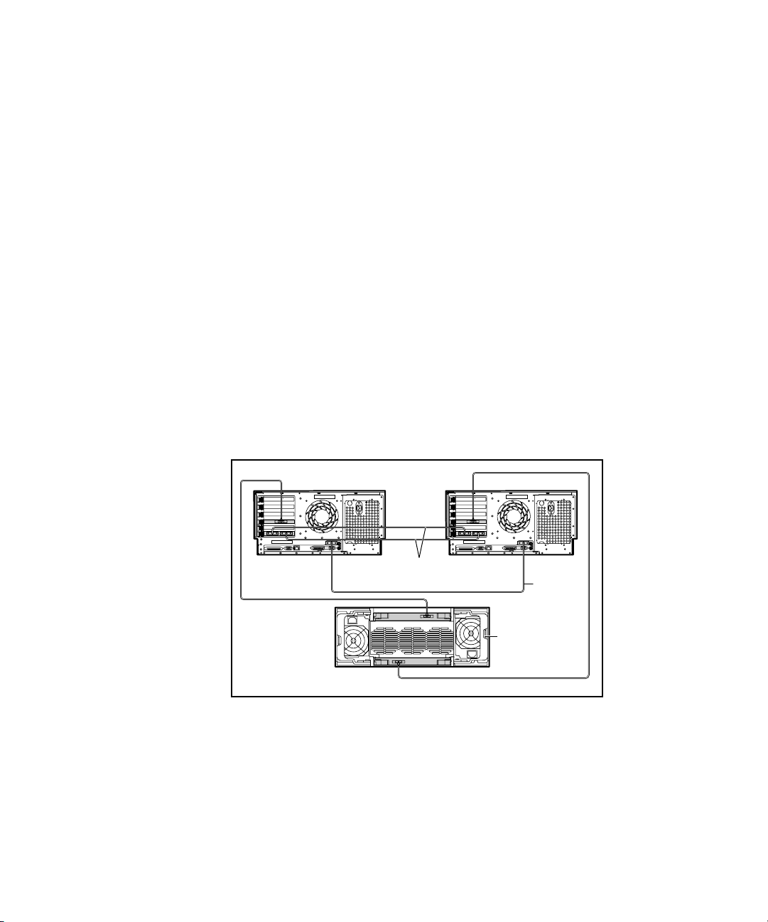
A ServerNet I cluster interconnect uses the two ServerNet I PCI adapters and
two cables as shown in Figure 1-1.
Node 1 Node 2
X
Y
Dedicated
ServerNet I Cables
Figure 1-1. Example of hardware components of the ServerNet I cluster
interconnect configuration
CI Serial
Cable
RA4100
Clustering Overview 1-5
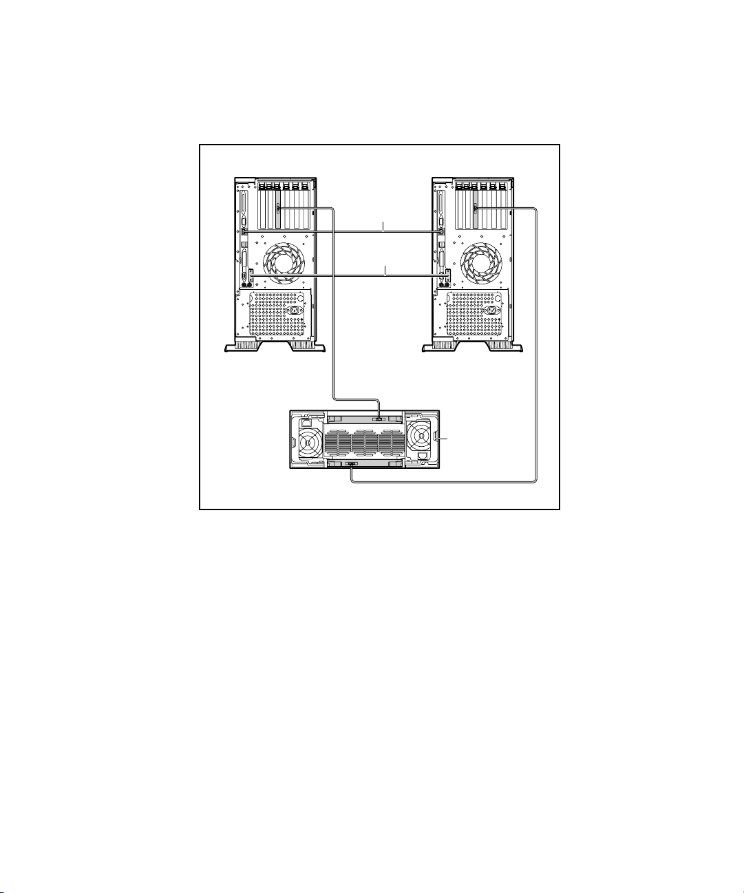
An Ethernet cluster interconnect uses the embedded NIC in each server
connected by one Ethernet crossover cable as shown in Figure 1-2.
Node 1 Node 2
Ethernet Crossover
Cable
CI Serial Cable
RA4100
Figure 1-2. Example of hardware components of the Ethernet cluster
interconnect configuration
LAN Connection
Clusters using Ethernet interconnect require an NC3123 NIC installed into
slot 1 of each node before cluster software installation so that the cluster can
access a public network. These NICs must be on a different subnet from the
embedded Ethernet cluster interconnect. Multiple public network controllers
can be installed after cluster installation is complete. For a list of certified
NICs, see the Compaq High Availability website at
http://www.compaq.com/highavailability
Clusters that use ServerNet I interconnect access the public network using the
embedded NIC. Each server must be connected to the same network.

1-6 Compaq ProLiant Clusters for SCO UnixWare 7 U/300 Quick Install Guide for the Compaq ProLiant ML370
Software Components
Software components of the U/300 kit for the ProLiant ML370 server include:
■ SCO UnixWare Release 7.1.1 Compact Media Kit
■ SCO UnixWare 7 NonStop Clusters Media Kit Version 7.1.1+IP
■ Compaq ProLiant Clusters for SCO UnixWare 7 ML370 Quick Install
CDs for the Compaq ProLiant ML370 server
Cluster-related software provided with the ProLiant ML370 server includes:
■ Compaq SmartStart™ and Support Software CD
■ Compaq Management CD
Additionally, you must obtain software licenses.
NOTE: SCO UnixWare 7 (with Mirroring Option or Online Data Manager) and UnixWare 7
NonStop Clusters software licenses must be purchased through your SCO reseller or
distributor. To locate a convenient SCO reseller or distributor to purchase licenses, see the
SCO website at
http://www.sco.com
SCO UnixWare Software
SCO UnixWare 7 and the SCO UnixWare 7 NonStop Clusters software
provide the operating environment for the ProLiant Clusters for
SCO UnixWare 7. The SCO UnixWare 7 NonStop Clusters software provides
the technology to:
■ Perform single-system image operations
■ Perform failover
■ Define and modify cluster members
■ Manually control and administer the cluster
■ View the current state of the cluster
This software is included in the U/300 kit.
NOTE: The U/300 kit includes SCO UnixWare 7.1.1 and SCO UnixWare NonStop
Clusters 7.1.1+IP. Other versions of the operating system and cluster software are not
supported by this kit.

Clustering Overview 1-7
NOTE: SCO UnixWare 7 (with Mirroring Option or Online Data Manager) and UnixWare 7
NonStop Clusters software licenses must be purchased through your SCO reseller or
distributor. To locate a convenient SCO reseller or distributor to purchase licenses, see the
SCO website at
http://www.sco.com
Quick Install CDs for the ProLiant ML370 Server
The Quick Install CDs for the ProLiant ML370 server provide rapid and
simplified cluster installation. These CDs contain all the necessary software
already configured for immediate cluster boot. An installation wizard allows
you to enter parameters and licenses specific to your configuration.
The Quick Install CDs for the ProLiant ML370 server contain a
readme.html
file, which includes descriptions of potential problems and how to avoid or
correct them.
The Quick Install CDs for the ProLiant ML370 server also include the
following utilities:
■ NonStop Clusters Verification Utility (NSCVU)
The NSCVU validates Compaq ProLiant Clusters for SCO UnixWare 7
and their components. The NSCVU is run from any node in the cluster
and tests cluster configuration in the following categories:
G ServerNet I connectivity tests verify that the nodes in the cluster can
communicate over X and Y ServerNet I paths.
G Ethernet connectivity tests verify that the nodes can communicate
over the Ethernet cluster interconnect.
G Storage tests verify the presence of, and minimum configuration
requirements of, supported HBAs, array controllers, and external
storage subsystems.
G System software tests verify that SCO UnixWare 7 and SCO
UnixWare 7 NonStop Clusters software have been properly
installed.
For further information on running the NSCVU, refer to the nscvu(1M)
manual page, which can be viewed with the man(1M) command or in the
SCOhelp online documentation set.
■ Uninterruptible Power Supply (UPS) software
This software provides management capabilities for UPSs connected to
the cluster.

1-8 Compaq ProLiant Clusters for SCO UnixWare 7 U/300 Quick Install Guide for the Compaq ProLiant ML370
Compaq Insight Manager™ Agents
■
These agents provide system information to the Compaq Insight
Manager, which is available on the Management CD that comes with
the ProLiant servers.
Compaq ServerNet Verification Utility (SVU)
The Compaq ServerNet Verification Utility (SVU) verifies proper installation
and cabling of the Compaq ServerNet I interconnect before a UnixWare
software installation. The SVU is a utility run from bootable diskettes inserted
into each cluster node. For more information on creating the diskettes and
running the SVU, refer to Chapter 3, “Installing Cluster Software,” of this
guide.
Compaq SmartStart and Support Software CD
SmartStart is located on the SmartStart and Support Software CD shipped with
ProLiant servers. This CD is required for ServerNet I configurations. You can
also use the CD to configure additional hardware. For information concerning
SmartStart, refer to the Compaq Server Setup and Management package that
comes with your server. The following utilities on the SmartStart CD are used
for your cluster:
■ Compaq Array Configuration Utility (ACU)
The Compaq ACU is an offline tool that is used to configure the array
controller, add disk drives to an existing configuration, and expand
capacity.
■ Options ROMPaq™ Utility
The SmartStart and Support Software CD contains the Options
ROMPaq Utility. Options ROMPaq updates the firmware on the disk
drives and controller.
■ Fibre Channel Fault Isolation Utility (FFIU)
The FFIU verifies the integrity of the Fibre Channel Arbitrated Loop
(FC-AL) installation. This utility provides fault detection and help in
locating a failing device on the FC-AL.

Clustering Overview 1-9
Compaq Management CD
The Compaq Management CD shipped with ProLiant servers contains
software for managing Compaq clusters. The Compaq Insight Manager is
included on the CD along with Compaq Management Agents and Tools for
Servers for SCO UnixWare 7 NonStop Cluster. The Quick Install process
automatically installs the agents and tools.
■ Compaq Insight Manager
Compaq Insight Manager is an easy-to-use Microsoft Win32 software
utility for collecting server and cluster information. Compaq Insight
Manager performs the following functions:
G Monitors fault conditions and system status
G Monitors shared storage and interconnect adapters
G Forwards server alert fault conditions
G Remotely controls servers
In Compaq servers, each hardware subsystem, such as disk drive
storage, system memory, and system processor, has a robust set of
management capabilities. Compaq Insight Manager notifies the system
administrator of impending fault conditions.
For information concerning Compaq Insight Manager, refer to the
Compaq Server Setup and Management package. See Chapter 4,
“Managing Clusters,” for more information.
■ Compaq Management Agents and Tools for Servers for SCO
UnixWare 7 NonStop Clusters.
SCO UnixWare 7 NonStop Clusters and SCO UnixWare 7 agents and
tools include the Compaq Insight Manager agents, the NSCVU
software, and the UPS management software described in “Quick Install
CDs for the ProLiant ML370 Server” earlier in this chapter and in detail
in Chapter 4.
Software Licenses
Licenses for UnixWare 7 (with Mirroring option or Online Data Manager) and
UnixWare 7 NonStop Clusters are not provided in the cluster kit. The licenses
must be purchased from an authorized SCO reseller. To locate a SCO reseller,
visit the following URL:
http://www.sco.com

1-10 Compaq ProLiant Clusters for SCO UnixWare 7 U/300 Quick Install Guide for the Compaq ProLiant ML370
Overview of Cluster Assembly and Software Installation Steps
Use the following general steps to set up your cluster hardware, initialize the
hardware, and install the software. The specific procedures are found in the
sections noted in these steps:
1. Set up the cluster hardware.
Cluster hardware assembly includes the following tasks:
G Setting up the rack that contains the server and storage components
if your cluster uses a rack. Refer to the section “Assembling the
Rack” in Chapter 2, “Setting Up Cluster Hardware.”
G Setting up the cluster nodes so that they include the hardware
required for cluster operation, including internal disk drives,
adapters, and NICs. To set up the cluster nodes, refer to “Setting up
the Cluster Nodes” in Chapter 2.
G Setting up external storage hardware components according to the
documentation that came with them. Once you have set up the
hardware, you must cable the hardware. To set up the external
storage, refer to “Setting up the External Storage Hardware” in
Chapter 2.
2. Perform preinstallation tasks.
Before beginning any software installation procedures, you must
perform a few tasks to prepare for the installation. You must obtain SCO
UnixWare 7 and SCO UnixWare 7 NonStop Clusters licenses, read
through all the installation procedures to become familiar with them, fill
out the installation worksheets in Appendix B of this guide, and ensure
that the servers each contain a single disk drive. Refer to the section
“Understanding Preinstallation Tasks and Considerations” in Chapter 3,
“Installing Cluster Hardware.”
3. Configure the servers.
Configuring the servers involves erasing any existing configuration and
using the SmartStart CD to set up the servers to use the SCO
UnixWare 7 operating system. Refer to “Configuring the Servers” in
Chapter 3.

Clustering Overview 1-11
4. Upgrade controller firmware.
Firmware provides an interface between hardware and software. It is
important to use the latest firmware for full hardware functionality.
Upgrading controller firmware is performed using a diskette created as
part of server configuration. Refer to “Updating Controller Firmware” in
Chapter 3.
5. Verify ServerNet I connections.
If your cluster uses the ServerNet I cluster interconnect, you must ensure
that the hardware for the interconnect is properly installed. This
procedure instructs you to perform tests of the adapters and the cables.
Refer to “Verifying ServerNet I Connections” in Chapter 3.
6. Install the software.
Installing the software provides your cluster with the SCO UnixWare 7
operating system and the SCO UnixWare 7 NonStop Clusters software
discussed in this chapter. You must select the Quick Install CDs for your
configuration and install the software on both nodes. Installation
prompts guide you through the installation and request the information
found in your completed worksheets. Refer to “Installing the Cluster
Using Quick Install” in Chapter 3.
The following sections offer sources of information and support for
application installation and cluster documentation.
Resources for Application Installation
Client/server software applications are among the key components of any
cluster. Compaq is working with its key software partners to ensure that
cluster-aware applications are available and that the applications work
seamlessly on Compaq ProLiant Clusters for SCO UnixWare 7.
Compaq white papers provide information about installing applications in
Compaq ProLiant Clusters for SCO UnixWare 7. Visit the Compaq High
Availability website to download cluster-related white papers and other
technical documents at
http://www.compaq.com/highavailability
IMPORTANT: Some software applications may need to be updated to take advantage of
clustering. Contact the software vendors to check whether their software supports SCO
UnixWare 7 NonStop Clusters and to ask whether any patches or updates are available for
SCO UnixWare 7 NonStop Clusters operation.

1-12 Compaq ProLiant Clusters for SCO UnixWare 7 U/300 Quick Install Guide for the Compaq ProLiant ML370
Other References
For more information about the RA4100 storage subsystem or RA4000
redundant array controller, refer to the following guides, either as included
with your hardware or as found at the Compaq Support website at
http://www.compaq.com/support/
■ Compaq StorageWorks RAID Array 4100 User Guide
■ Compaq StorageWorks RAID Array 4100 Configuration poster
■ Compaq StorageWorks RAID Array 4000 Redundant Array Controller
Configuration poster
■ Compaq Fibre Channel Storage System User Guide
■ Compaq StorageWorks Fibre Channel Host Adapter Installation Guide
■ Compaq Fibre Channel Troubleshooting Guide
■ Compaq Fibre Channel Storage System Technology
For more information about cluster use and administration, refer to the SCO
UnixWare 7 NonStop Clusters System Administrator’s Guide, located in the
SCOhelp online documentation set in the NonStop Clusters Documentation
topic.
SCO UnixWare 7 NonStop Clusters Documentation
The SCO UnixWare 7 NonStop Clusters software includes online
documentation, which you can view after the cluster is installed. The main
documentation set is called SCOhelp and contains information that can answer
many administrative questions. SCOhelp is available when you use the
UnixWare Desktop and remotely using a Web browser when your cluster is
connected to the public network. Additionally, you can access manual pages
using the
Access the online documentation in the following ways:
■ Click the book-and-question-mark icon in the toolbar on the UnixWare
■ Type scohelp at the command line of a desktop terminal (dtterm) to access
man(1M) command.
Desktop to access SCOhelp. A browser displays the main SCOhelp list
of topics.
SCOhelp. A browser displays the main SCOhelp list of topics.

Clustering Overview 1-13
Use the following URL to access SCOhelp remotely when the cluster is
■
attached to the public network:
http:// clustername:457
Substitute the name of your cluster or its CVIP address for clustername.
The browser displays the main SCOhelp list of topics.
■ Use the man command to access manual pages from any command line
by entering
man and the name of the command, file, or routine about
which you want information. For example, enter:
man cluster
The man command displays the reference page for the cluster command.

Chapter 2
Setting Up Cluster Hardware
Setting up a cluster includes setting up, cabling, and verifying hardware
components. Use the following sections to set up the Compaq ProLiant
Clusters for SCO UnixWare 7 U/300 for the Compaq ProLiant ML370 Quick
Install Cluster:
■ Assembling the Rack
■ Setting Up the Cluster Nodes
■ Setting Up the External Storage Hardware
■ Cabling the Components
For specific information about individual components, see the documentation
that comes with the component. For information on steps and procedures for
setting up cluster hardware, refer to the documentation that comes with the
hardware.

2-2 Compaq ProLiant Clusters for SCO UnixWare 7 U/300 Quick Install Guide for the Compaq ProLiant ML370
Assembling the Rack
In clusters that use racks, rack assembly requires careful attention to avoid
problems.
Evaluate the site where the cluster is to be installed by checking the path and
setup area.
■ Check the path from the receiving dock to the installation area for the
following conditions:
G Height and width of doors
G Ceiling height and overhead obstacles
G Change in slope of the floor or change in other elevation
G Floor roughness, texture, gaps, and obstacles
G Floor load capacity
■ Check the area where the hardware is to be unpacked for the following
conditions:
G Adequate proximity to installation area
G Maneuvering room
G Room to disassemble the crate
G Room for the ramp and for rolling the hardware off the crate
■ Check the installation area for the following conditions:
G Adequate power needs, including outlets, breakers, electrical quality,
and grounding
G Cooling capacity
G Cable handling capacity
G Floor load capacity
G Clearance for the equipment

Stacking Components
Keep in mind the following considerations while stacking components in a
rack:
■ Put the UPSs in the bottom of the rack.
■ Assemble other components into the rack from the bottom up.
■ Put the heaviest equipment per U of height in the bottom of the rack
whenever possible.
■ Install non-flat-panel monitors toward the top of the rack.
■ Install components that require better cooling capacity toward the top of
the rack.
■ Purchase the rack stabilizer feet option when offered.
The typical stacking order has the UPSs at the bottom and progresses upward
according to the following list:
■ UPS
■ Storage subsystems
■ Node 1 and node 2
Setting Up Cluster Hardware 2-3
■ Keyboard/mouse/monitor switch
■ Monitor and expansion nodes
CAUTION: Load the racks from the bottom up to avoid tipping the rack.

2-4 Compaq ProLiant Clusters for SCO UnixWare 7 U/300 Quick Install Guide for the Compaq ProLiant ML370
Transporting Racks
Before transporting a filled rack, read the documentation that comes with the
rack to determine the safety measures to take for successful transportation.
Never transport a rack without first reviewing the documentation.
Develop standard procedures for securing rack equipment depending on the
rack and its components. Standard procedures include:
■ Verify that the rack is secured to the pallet.
■ Remove all loose items from the rack and the pallet.
■ Disconnect the cabling, ensuring that cables are disconnected from any
expansion cabinets and that you have labeled the cables for trouble-free
reconnection. Protect, coil, and stow the cables in the cabinet base.
■ Confirm that all major cable bundles are well-secured.
■ Insert anti-static foam between components in the rack.
■ Wrap the front and rear doors of the rack in bubble wrap before securely
closing them.
■ Crate the rack according to the documentation that comes with the rack,
including protective wrapping, banding components, and any external
packaging.
■ Label the crate properly with handling information, using statements
such as This End Up, No Forklifts, Top Heavy, and Do Not Double
Stack.
■ Include tilt watch for X and Y directions and shock watch indicators.
Use these guidelines in addition to rack documentation to secure the rack for
transportation.

Setting Up the Cluster Nodes
Setting up the cluster nodes includes:
■ Installing the 64-bit Fibre Channel Host Bus Adapter (HBA) into slot 3
of each node and Gigabit Interface Converters Shortwave (GBIC-SW)
into each adapter
■ Installing one 9.1-GB or larger internal disk drive on each node
■ Installing the public LAN NIC Compaq NC3123 Fast Ethernet NIC
(NC3123 NIC) PCI 10/100 WOL into slot 1 for clusters using Ethernet
interconnect
■ Installing the ServerNet I cluster interconnect
NOTE: No installation is required for Ethernet interconnects, which use the embedded
NIC. Refer to the section, “Cabling the Ethernet Interconnect,” later in this chapter for
installing the Ethernet interconnect cable.
Additional options, such as tape drives, other NICs, and Remote Insight
Lights-Out Edition boards can be installed after the cluster Quick Install
procedure has completed.
Setting Up Cluster Hardware 2-5
Installing the 64-Bit External Storage Fibre Channel
HBA and GBIC-SWs
For a redundant fault-tolerant configuration, the storage system connects to
both ProLiant ML370 servers, so an HBA must be installed in each server.
Additionally, a GBIC-SW must be installed in each adapter.
The following steps explain how to install the external Fibre Channel HBAs,
which are required for the Compaq StorageWorks RAID Array 4100
(RA4100):
NOTE: Refer to the ProLiant ML370 server documentation for general PCI adapter
installation information.
1. Install one 64-bit HBA into slot 3 of each node.
IMPORTANT: Only one Fibre Channel HBA is supported in each node.
2. Install one GBIC-SW module into each HBA. For installation
instructions, refer to the documentation that comes with the Fibre
Channel hardware.

2-6 Compaq ProLiant Clusters for SCO UnixWare 7 U/300 Quick Install Guide for the Compaq ProLiant ML370
3. Do not install or update drivers. The Quick Install procedures install the
Fibre Channel drivers.
Installing Internal Disk Drives
One 9.1-GB disk drive is required per node. The Quick Install automatically
configures each internal drive with a 9.1-GB partition, even if the disk drive is
larger than 9.1-GB. This UnixWare partition cannot be modified, and other
UnixWare partitions cannot be added to this disk drive. After the Quick Install
is completed, non-UnixWare partitions can be added up to the maximum
capacity of the disk drive, or other disk drives can be installed for additional
partitions.
To install the internal disk drives, refer to the documentation included with the
drive and with the ProLiant ML370 server.
Installing the Public LAN NIC into a Cluster Ethernet Interconnect
To connect a cluster using Ethernet interconnect to a public network, install an
NC3123 NIC into slot 1 of each node using the documentation that comes with
the NIC. This step is not needed for clusters that use the ServerNet I
interconnect.
Installing the ServerNet I Cluster Interconnect
If your ProLiant ML370 cluster uses ServerNet I as the cluster interconnect,
you must install the ServerNet I PCI adapter into slot 1 of each server. To
install the ServerNet I PCI adapter, refer to the documentation that comes with
the adapter for general installation guidelines.
■ Install one ServerNet I PCI adapter version 1.5e into slot 1 of each node.
■ Ignore the ServerNet I driver installation instructions in the adapter
installation guide. The required UnixWare ServerNet I device driver is
included with the SCO UnixWare 7 NonStop Clusters software and is
automatically installed during software installation.
■ Ignore the ServerNet I connection testing instructions in the adapter
installation guide. The software installation procedure includes testing
the connection.

Setting Up the External Storage Hardware
IMPORTANT: The RA4100 is shipped with a single RAID controller. Each RA4100 array
used in Compaq ProLiant Clusters for SCO UnixWare 7 requires an additional, redundant
controller.
NOTE: The Quick Install automatically configures an RA4100 drive with a RAID 1 9.1-GB
UnixWare partition, even if the disk drive is larger than 9.1-GB. This partition cannot be
modified and other UnixWare disk drive partitions cannot be added to this disk drive. After
the Quick Install is completed, non-UnixWare partitions can be added up to the maximum
capacity of the disk drive, or other disk drives can be installed for additional UnixWare
partitions.
The U/300 cluster for the ProLiant ML370 server uses external storage with
the following components:
■ RA4100 storage subsystem
■ Two Compaq StorageWorks RAID Array 4000 (RA4000) controllers,
one included in the RA4100 storage
■ Two GBIC-SWs, one in each controller
■ Two 9.1-GB or larger disk drives
Setting Up Cluster Hardware 2-7
■ Fibre Channel cables
To configure the external storage for the U/300 Quick Install cluster, set up the
RA4100 storage subsystem according to the following steps:
1. Follow the set-up instructions in the documentation that comes with the
subsystem to set up the RA4100.
Review the section, “Fibre Channel Cable Precautions,” later in this
chapter for general information.
2. Refer to the user guide for the RA4100 for disk drive RAID array
options and considerations.

2-8 Compaq ProLiant Clusters for SCO UnixWare 7 U/300 Quick Install Guide for the Compaq ProLiant ML370
3. In each array, install one redundant controller into the lower slot
(rack-mount) or into the left slot (tower as viewed from the back)
according to the following steps:
a. Disconnect the power from the storage subsystem.
b. Remove the cover from the second controller slot.
c. Rotate the board 180 degrees from the position of the top controller.
d. Insert the RA4000 redundant controller.
e. Install the GBIC-SW modules.
4. Ignore the chapters on the Array Configuration Utility and the Options
ROMPaq in the documentation for the RA4100. These steps are part of
the installation procedure in Chapter 3, “Installing Cluster Software.”
5. Install a 9.1-GB or larger disk drive into each slot 0 of the array.
Cabling the Components
Proper cabling can simplify service and assembly of the cluster, so following
appropriate cabling standards is vital to a successful cluster setup.
Using Labeling Standards
Proper labeling can prevent improper connections and simplify cluster
assembly and service. Make sure to label each server with the correct node
labels that are provided.
Also, label the ends of the following cables:
■ Ethernet crossover cable (for cluster interconnects using Ethernet)
■ ServerNet I cables (for cluster interconnects using ServerNet I)
■ Cluster Integrity (CI) serial cable
■ Keyboard, monitor, and mouse cables
■ Server power cables
Each label must identify the node to which the cable connects.

Cabling the ServerNet I Interconnect
ServerNet I adapters include X and Y connections for redundancy. Figure 2-1
shows the ServerNet I adapter connections.
Port X Connector
Port Y Connector
Figure 2-1. ServerNet I PCI adapter connections
IMPORTANT: Cable X and Y to their corresponding counterparts. Do not cable
X connections to Y connections.
Setting Up Cluster Hardware 2-9
PCI Bus Connector

2-10 Compaq ProLiant Clusters for SCO UnixWare 7 U/300 Quick Install Guide for the Compaq ProLiant ML370
The ServerNet I cables directly connect the ServerNet I adapter in node 1 to
the ServerNet I adapter in node 2, as shown in Figure 2-2.
Node 1
X
Dedicated
ServerNet I Cables
Figure 2-2. Example of cabling the cluster interconnect of a cluster that uses
ServerNet I
NOTE: Cabling for the external storage is intentionally not shown.
Y
CI Serial Cable
Node 2
To Public
Network

Setting Up Cluster Hardware 2-11
Use the cabling suggestions illustrated in Figure 2-3 to label the ServerNet I
cables.
ServerNet I
Node
1
2
Switch Port
Number
0
1
Number
Figure 2-3. ServerNet I cable labeling suggestion
Cable
Tie
Color
Pink
Orange
X ServerNet I cables
are identified with
White cable ties.
X/Y Fabric
Identifier
Node
Identifier
Red ties are used only during
shipment and are to be removed
during onsite installation.
To cable the ServerNet I interconnect, follow these steps:
1. Connect a white-labeled ServerNet I X cable to the X connection on the
ServerNet I adapter in node 1.
2. Connect the other end of the cable to the corresponding ServerNet I
adapter X connection in node 2.
3. Complete the cabling by installing the ServerNet I Y cable in a similar
manner.

2-12 Compaq ProLiant Clusters for SCO UnixWare 7 U/300 Quick Install Guide for the Compaq ProLiant ML370
Cabling the Public LAN Connection
For interconnects using ServerNet I, connect the public LAN Ethernet cable to
the embedded NIC of the servers. See Figure 2-2 earlier in this chapter.
For interconnects using Ethernet, connect the public LAN Ethernet cable to the
NC3123 NIC into slot 1 of the servers. See Figure 2-4.
Node 1 Node 2
Ethernet Crossover
Cable
CI Serial Cable
To Public Network
Figure 2-4. Example of cabling the cluster interconnect of a cluster that uses
Ethernet
NOTE: Cabling for the external storage is intentionally not shown.
Cabling the Ethernet Interconnect
An Ethernet crossover cable is required for interconnects using Ethernet. To
cable the Ethernet interconnect, connect one end of the Ethernet crossover
cable to the embedded NIC in node 1. Connect the other end of the Ethernet
crossover cable to the embedded NIC in node 2. Figure 2-4 illustrates the
proper cabling.

Cabling the CI Serial Cable
IMPORTANT: The CI serial cable is required.
To cable the CI serial cable, connect one end of the CI serial cable to serial
port connector B in node 1. Connect the other end of the CI serial cable to
serial port connector B in node 2. Figure 2-2 illustrates the proper cabling for
clusters that use ServerNet I interconnect. Figure 2-4 illustrates the proper
cabling for clusters that use Ethernet interconnect.
Cabling the RA4100
To cable the RA4100 components, follow these steps:
1. Connect the Fibre Channel cabling between the arrays and nodes using
the instructions in the user guide for the RA4100 and the documentation
that comes with the Fibre Channel cables. See Figure 2-5 for a cabling
illustration.
Fibre Channel
Host Controller
Setting Up Cluster Hardware 2-13
GBIC (4 places)
Node 1 Node 2
Fibre Channel
Array Controller
SCSI Bus 2
543210
Figure 2-5. Supported cabling of the RA4100 storage subsystem for the
U/300 configuration
YX
SCSI Bus 1
Dual Fiber
543210
(viewed from rear)
Optic Cable
2. Connect the first RAID controller in the upper slot (rack-mount) or right
slot (tower as viewed from the back) of the RA4100 to node 1. Connect
the redundant, or second, controller in the lower (rack-mount) or left
(tower) slot to node 2.
3. Confirm that all cables are properly connected to the appropriate arrays
and servers.
Figure 2-5 shows the supported cabling of the RA4100 storage subsystem for
the U/300 configuration.

2-14 Compaq ProLiant Clusters for SCO UnixWare 7 U/300 Quick Install Guide for the Compaq ProLiant ML370
Fibre Channel Cable Precautions
Keep the following precautions in mind when installing, handling, moving,
connecting, and disconnecting Fibre Channel cables:
■ Affix cable labels carefully, without over-tightening, to avoid breaking
the glass fibers within the cables.
■ Do not bend the Fibre Channel cable into an arc tighter than the
minimum allowable bend radius specified by the cable manufacturer.
The minimum bend radius is usually 10 to 20 times the outer diameter
of the cable. Protect the cables from pinching, abrasion, excess tension,
and any other mechanical stress.
■ When inserting or removing connectors, handle the Fibre Channel cable
only by the connector body, not by the strain relief or by the cable body.
Even moderate amounts of tension or pressure on the Fibre Channel
cable body can destroy the connector.
■ Type SC connectors include a white stripe along each side. Verify that
the connectors mate with a positive click and that the white stripe is
invisible. If the white stripe is visible, the connectors are not properly
mated.
■ Do not subject connectors to abrasion, chemical contaminants, or rough
handling. Fibre Channel mating surfaces are cut, polished, and aligned
to extremely close tolerances, and they are much more sensitive to
mishandling than conventional electrical signal connectors.
■ Do not allow dust to enter the connectors.
■ Leave any protective dust covers on the GBIC-SW whenever it is not
connected to a Fibre Channel cable.
■ Failures caused by dust contamination or improper cable connector
handling can exhibit the same symptoms as a controller or GBIC-SW
failure, resulting in an unnecessary component replacement that does
not resolve the root cause of the problem.

Cabling the Keyboard, Monitor, and Mouse
To cable the keyboard, monitor, and mouse, refer to the documentation that
comes with these devices.
UPS Power Management Cabling
Compaq ProLiant Clusters for SCO UnixWare 7 support serial data
connections from UPS units to ProLiant server nodes in the cluster. This
feature provides the cluster with soft shutdown capability when an AC power
outage lasts until the UPS batteries approach the end of their holdup period.
To connect the UPS power management cable to the ProLiant server nodes:
1. Locate the cable. The UPS power management cable is a 3.66-m
(12.00-ft) serial cable included with most Compaq UPSs.
2. Connect one end of the cable to the COM port on the UPS chassis.
Connect the other end of the cable to any unused serial port on any
ProLiant server within the cluster. Because the power management
software is cluster-aware, you can connect the UPS power management
cable to any node in the cluster.
Setting Up Cluster Hardware 2-15
If a second UPS is used, repeat step 2. Connect the UPS serial cable to the
other server. Do not connect multiple cables to one server.

Chapter 3
Installing Cluster Software
Using the Compaq ProLiant Clusters for the SCO UnixWare 7 ML370 Quick
Install CDs for the Compaq ProLiant ML370 server to install the SCO
UnixWare 7 NonStop Clusters software on a ProLiant ML370 Cluster includes
several tasks. Use the following information to install your cluster:
■ Understanding Preinstallation Tasks and Considerations
■ Configuring the Servers with SmartStart
■ Updating Controller Firmware
■ Verifying ServerNet I Connections
■ Installing the Cluster Using Quick Install
■ Verifying the Cluster Assembly
■ Additional Cluster Setup Tasks
■ Registering the ProLiant Cluster for SCO UnixWare 7
■ Viewing UnixWare and NonStop Clusters Documentation
For specific information about individual software components, see the
documentation that comes with the component.

3-2 Compaq ProLiant Clusters for SCO UnixWare 7 U/300 Quick Install Guide for the Compaq ProLiant ML370
Understanding Preinstallation Tasks and Considerations
Before you begin the software installation, assemble the hardware for the
cluster, fill out the Quick Install planning worksheets in Appendix B of this
guide, and have four formatted diskettes on hand. Read through this chapter to
become familiar with the installation procedures as you fill out the worksheets.
Default Quick Install Settings
Table 3-1 lists the default settings used during the Quick Install installation
procedure. These parameters can be modified after the installation is complete
by running the International Settings Manager in the System folder of the
SCOadmin system administration tool.
Table 3-1
Quick Install Default Settings
Parameter Default
Locale C Standard
Keyboard United States C
Code set C
Time zone Configurable to any U.S. time zone
Internal Disk Drive Considerations
Before you begin any procedures in this chapter, do not have any disk drives
in the internal storage area other than the one 9.1-GB or larger disk drive. The
Quick Install procedures require that only one disk drive reside in each server
during the installation.
Obtaining UnixWare 7 Licenses
Before installing the SCO UnixWare 7 NonStop Cluster software, obtain a
UnixWare 7 license that includes either the Mirroring Option or an OnLine
Data Manager (ODM) license. To locate a convenient SCO reseller or
distributor to purchase licenses, see the SCO website at
http://www.sco.com

Configuring the Servers with SmartStart
Before cluster installation on each node, you must erase any existing
configuration and configure each server using the SmartStart CD that comes
with the ProLiant ML370 server. You must also set two hardware
configuration items on each server. Start with the server that you plan to use as
node 1.
Erasing the Configuration
If you are using server or storage hardware that has been previously
configured, you must erase that configuration on each node before using the
Quick Install CDs for the ProLiant ML370 server. The following steps must be
used separately on each node to erase the configuration:
CAUTION: This procedure erases any information currently stored on the node.
To prevent information loss, back up important files before attempting
installation.
NOTE: The SmartStart procedure may prompt you for the Server Profile Diskette that
comes with the server. If prompted, insert the diskette and follow the onscreen
instructions.
Installing Cluster Software 3-3
1. If you are performing this procedure on node 1, power up the Compaq
StorageWorks RAID Array 4100 (RA4100) and wait about 90 seconds
for the Compaq StorageWorks RAID Array 4000 (RA4000) controllers
to complete their Power-On Self-Tests (POSTs).
If you are performing this procedure on node 2, power down the
RA4100.
2. Power up the node, insert the SmartStart CD into the CD-ROM drive for
the node, and then wait for SmartStart to boot.
3. Select the Run System Erase Utility icon, and then click OK.
4. Click the Yes button when prompted to continue. Wait for the
configuration to be erased.

3-4 Compaq ProLiant Clusters for SCO UnixWare 7 U/300 Quick Install Guide for the Compaq ProLiant ML370
5. If you used the Server Profile Diskette, remove it. Power down the
RA4100 if you are erasing the configuration on node 1. When prompted,
power down, and then power up only the server.
IMPORTANT: Do not turn the RA4100 back on at this time.
Continue with the following procedure for server configuration. Begin with
step 2 because you have erased a previous configuration.
Configuring the Servers
To configure the nodes using SmartStart:
IMPORTANT: The RA4100 must not be powered up during this procedure. Do not
configure any RA4100 logical disks prior to software installation; an RA4100 logical disk
is automatically configured by the Quick Install procedure.
1. If you did not erase a configuration, power up the server, and then insert
the SmartStart CD into the CD-ROM drive for node 1. If you erased a
configuration according to the preceding steps, begin with step 2.
2. Select the language at the prompt. The Regional Settings screen displays.
3. Select the country and keyboard type from the Regional Settings screen.
4. Set the date, time, and daylight savings time adjustment if applicable.
5. Click Next, and then click Continue. The License Agreement displays.
6. Accept the License Agreement to continue. An Installation Path window
displays.
7. Select Manual Configuration, and then click the Begin button.
8. Click the plus sign (+) preceding the SCO entry in the menu. A list of
operating systems displays.
9. Select SCO UnixWare 7.1.1, and then click Next. A warning screen displays.
10. Click Continue. Wait while the system configuration loads.
11. Use the arrow keys to select Review or modify hardware settings, and press
Enter. The
Steps in configuring your computer window displays.
12. Use the arrow keys to select Step 3: View or edit details, and then press
Enter.
13. Page down to the Embedded - Compaq Automated Server Recovery entry.

Installing Cluster Software 3-5
14. Verify that the following items are disabled:
G Software Error Recovery
G Standby Recovery Server
G UPS Shutdown
Use the arrow keys to select the options and the Enter key to modify
them as necessary.
15. Page down to Embedded-Compaq Integrated Dual Channel Wide Ultra2 SCSI
Controller (Port2).
G Select Controller Order, and then press Enter.
G Select First and press F10. The Configuration Changes screen displays.
G Press Enter to accept the changes.
16. Press F10 to exit the Step 3: View or edit details window. The Steps in
configuring your computer
window displays.
17. Use the arrow keys to select Step 5: Save and exit, and then press Enter.
The
Step 5: Save and exit window displays.
18. Select Save the configuration and restart the computer, and then press Enter. A
Reboot window displays.
19. Press Enter. The Array Configuration Utility loads and an error message
indicates that no array controllers were detected. This message is an
expected error message.
20. Click OK to exit the Array Configuration Utility. The system reboots.
21. Wait while the system partition installation completes. The server
reboots and sets up hardware. After multiple reboots, the
SmartStart-Manual Path
window displays.
Compaq
22. Create a firmware diskette at this time if you are completing this step on
node 1. You will use this diskette later to upgrade the RA4000 controller
firmware. If performing this procedure on node 2, skip this step and
continue with the section “Updating Controller Firmware.”
To create a firmware diskette, obtain one DOS formatted diskette, and
follow these steps:
a. Click the Create Support Software button.
b. Click the plus sign (+) next to Compaq.

3-6 Compaq ProLiant Clusters for SCO UnixWare 7 U/300 Quick Install Guide for the Compaq ProLiant ML370
c. Page down to Options ROMPaq, select it, and then click Next. Although
the onscreen instructions indicate that you need 10 diskettes, this
procedure creates only a single diskette. A screen for creating the
first diskette displays.
d. Click Skip. The Firmware Upgrade diskette for the RA4000 Controller
displays.
e. Insert the formatted diskette into the disk drive, and then click OK.
f. Wait for the software to be written to the diskette.
g. Remove the diskette from the drive after the software has been
written to the diskette.
h. Click Skip on each of the remaining screens, and then click Finish
at the final screen to return to the
Compaq SmartStart-Manual Path
window.
23. Click Next. A Compaq SmartStart-Manual Path warning window displays.
24. Remove the SmartStart CD and power down the node.
25. Repeat the procedures for erasing a configuration (if necessary) and
configuring servers on node 2. Do not repeat step 22 on node 2.
If you have erased any existing configuration on both nodes of your server and
have configured both nodes with SmartStart, continue with the following
section, “Updating Controller Firmware” to upgrade controller firmware.

Updating Controller Firmware
Controller firmware must be updated on both nodes. Use the following
procedure to upgrade the controller firmware:
1. Turn on the RA4100 and wait about 90 seconds for the RA4000
controllers to complete their POSTs.
2. Insert the firmware upgrade diskette into the drive. (You made this
diskette in the preceding procedure.)
3. Boot the node from the diskette, and then follow the prompts on the
screen until the firmware is updated.
4. Remove the firmware diskette and upgrade the controller firmware on
node 2 using step 2 and step 3 of this procedure.
Continue with one of the following procedures when the firmware is
updated:
G Continue with the “Verify the ServerNet I Connections” section for
cluster interconnects using ServerNet I.
G Continue with the “Installing the Cluster Using Quick Install”
section for cluster interconnects using Ethernet.
Installing Cluster Software 3-7
Verifying ServerNet I Connections
NOTE: This section applies only to clusters connected with ServerNet I. If the cluster is
connected with Ethernet, proceed to the next section, “Installing the Cluster Using Quick
Install.”
To verify the ServerNet I connections, create a ServerNet utility diskette for
each node. To create the diskettes, download the ServerNet Verification
Utilities Softpaq from the following site:
http://www.compaq.com/support
From the welcome window of that site, take the following path:
1. Select software & drivers. A download center window displays.
2. Select servers.

3-8 Compaq ProLiant Clusters for SCO UnixWare 7 U/300 Quick Install Guide for the Compaq ProLiant ML370
3. From the options presented to you, select the following:
G Select your particular server from the list presented to you.
G Select the appropriate model or All Models.
G Select SCO UnixWare 7 from the list of operating systems.
4. Select the Softpaq for ServerNet Verification Utilities.
At the download page, follow the directions for downloading the Softpaq and
creating diskettes. Create two ServerNet Verification Utilities diskettes.
Verifying the Local Adapter
To verify that the local ServerNet I adapter is properly installed and
functional, on each node that has a ServerNet I adapter, follow these steps:
1. Have a ServerNet I Verification Utilities diskette for each server.
2. Insert the proper diskette into the server that you want to test. Reboot
the node. Wait for the DOS prompt to be displayed.
3. Type spaf at the DOS prompt, and then press Enter. A title screen
displays.
4. Press any key to start the test of the ServerNet I links. The following
messages display:
LINK X IS ALIVE
LINK Y IS ALIVE
Verify that the links are alive. If either link is reported NOT ALIVE, a
problem exists with the adapter. Press Esc to stop the ServerNet I link
test. Power down the server, disconnect all power to the server, reseat
the board, and then repeat the test.
5. Press Esc to exit the ServerNet I Utility or press any other key to start
the loopback test. The loopback test status displays. If a loopback error
occurs, the error displays, and the test fails.
6. Press any key to stop the loopback test.

Verifying Node-to-Node Communication
Node-to-node communication tests include a link test for the cables and a
loopback test for the adapters. Use the following steps to verify node-to-node
communication on a directly connected ServerNet I two-node cluster:
1. Insert a ServerNet Utility Disk into node 1 and node 2, and then reboot
the nodes. Wait for the DOS prompt on the nodes.
2. Type spaf 1 2 at the DOS prompt on node 1, and then press Enter. A title
screen displays.
3. Type spaf 2 1 at the DOS prompt on node 2, and then press Enter. A title
screen displays.
4. Press Enter on both nodes to start the link test for the cables. The
following messages display:
LINK X IS ALIVE
LINK Y IS ALIVE
You may see errors on the first node until the second node test starts. Be
sure that both nodes have started the test before checking for errors.
Persistent errors indicate a problem with the cabling between the nodes.
Installing Cluster Software 3-9
5. Exit the text by pressing Esc if errors persist. Resolve the problem
before continuing.
6. Press Enter on node 1 to begin the loopback test. Test message similar
to the following display:
spaf: path=0 Loopback=0 Option=1 11/29 14:08:20 600 pages
spaf: path=1 Loopback=0 Option=1 11/29 14:08:21 600 pages
If a loopback error occurs, the test stops and reports the error. The error
indicates a problem with the adapter on node 1. Exit the loopback test
by pressing Esc, and resolve the problem before continuing.
7. Press Enter on node 2 to begin the loopback test. Test message similar
to the following display:
spaf: path=0 Loopback=0 Option=1 11/29 14:08:25 19888 pages
spaf: path=1 Loopback=0 Option=1 11/29 14:08:26 19999 pages
If a loopback error occurs, the test stops and reports the error. The error
indicates a problem with the adapter on node 2. Exit the loopback test
by pressing Esc, and resolve the problem before continuing.
8. Press Enter on each node to exit the loopback test.

3-10 Compaq ProLiant Clusters for SCO UnixWare 7 U/300 Quick Install Guide for the Compaq ProLiant ML370
Installing the Cluster Using Quick Install
Before beginning the software installation, be sure to have the Quick Install
planning worksheets on hand and the following items available:
■ Cluster name and Cluster Virtual IP (CVIP) address
■ Node 1 hostname and IP address for the public network
■ Node 2 hostname and IP address for the public network
■ Netmask for the public network
■ For clusters using Ethernet interconnect, node 1 hostname and IP
address for the cluster interconnect
Default values of node1-ic and 10.1.0.1 are provided during the
installation.
■ For clusters using Ethernet interconnect, node 2 hostname and IP
address for the cluster interconnect
Default values of node2-ic and 10.1.0.2 are provided during installation.
IMPORTANT: The public network IP address for node 1 and node 2 and the CVIP address
must be on the same Ethernet subnet. The default router must be on the public network
subnet. The cluster interconnect IP addresses for node 1 and node 2 must be on a
different subnet from the public network.
■ For clusters using Ethernet interconnect, netmask for the cluster
interconnect interfaces
A value of 255.255.255.0 is provided during installation.
■ UnixWare and NonStop Clusters licenses and an add-on Mirroring
Option license or ODM license must be added if the UnixWare licenses
do not include mirroring
■ Passwords and system owner information
■ NonStop Clusters simple network management protocol (SNMP) agent
configuration information
■ One formatted diskette
■ The correct set of Quick Install CDs for the ProLiant ML370 server.
Choose either ServerNet I or Ethernet, according to your server and
cluster configuration

Installing Node 1
Before beginning the installation, select the set of Quick Install CDs for your
cluster configuration. Choose the CDs for either the ServerNet I cluster
interconnect or Ethernet cluster interconnect.
NOTE: To save time, you can install both nodes together. Be sure node 1 has rebooted
before rebooting node 2. Insert the CDs into the servers, power up the servers, and follow
the procedures for each node at the same time.
To install the software on node 1, follow these steps:
1. Turn on the RA4100 and wait about 90 seconds for the RA4000
controllers to complete their POSTs.
2. Power up node 1, and then insert Quick Install Image CD for node 1 into
the CD-ROM drive. Wait while node 1 boots from the CD. A warning
message indicates that data will be lost.
3. Press Enter to continue, or power down the system to abort the
installation.
The software begins to load and a progress bar indicates the installation
progress. When all software has been loaded, several screens request
necessary information.
Installing Cluster Software 3-11
4. Provide the necessary information for the following screens. Each of the
screens mentioned in step 3 displays the fields and a brief description of
each field as it is selected for entry (for detailed help, press F1).
a. Read responses from previously saved diskette?
This screen provides the opportunity to restore responses from a
previous installation.
Use the arrow key to select No to skip reading responses or if this is
the first installation. Responses can be saved later.
Use the arrow key to select Yes to read the answers from a diskette
and present them as defaults in the remaining screens.
Use the arrow key to select Force to read the answers from a diskette,
and then apply them without modification. The date is assumed to be
correct on the system and is not modified.

3-12 Compaq ProLiant Clusters for SCO UnixWare 7 U/300 Quick Install Guide for the Compaq ProLiant ML370
b. Date, Time, and Time Zone
Modify the current date, time, and time zone as necessary. Only U.S.
time zones are available during Quick Install. Time zone information
can be changed after Quick Install by using the UnixWare
SCOadmin system administration tools. For more information, see
the “Understanding Preinstallation Tasks and Considerations”
section in this chapter.
c. Cluster name
Enter the name of the cluster.
d. System owner identity and passwords
Enter the full name of the system owner, the system owner login ID,
and the system owner and root passwords. Passwords are not
displayed and must be repeated to verify that they are entered
correctly.
e. IP interconnect
NOTE: The IP interconnect screen is not displayed during the installation of ServerNet I
cluster interconnects.
Accept the default values, or enter the node 1 hostname and IP
address for the cluster interconnect, the node 2 hostname and IP
address for the cluster interconnect, and the netmask. The Ethernet
cluster interconnect addresses must be on the same network.
f. Network configuration
Enter the external network configuration: domain name, CVIP
address, netmask, node 1 hostname and IP address for the public
network, node 2 hostname and IP address for the public network,
and default route. The public network addresses must be on the same
network.
g. NSC SNMP agent configuration
Enter the name of the person responsible for the cluster and the
location of the cluster. Default values are supplied for the other
fields. Each field is described in the lower region of the screen as
you tab to the field. Press F1 for information that can help you to fill
out the fields.
h. Save responses
Responses can be saved, except for the date, to a formatted diskette
for future installations. Unencrypted passwords are not saved.
A final screen indicates that the installation is complete.
5. Remove the CD, and then press Enter to reboot. The SCOadmin license
manager automatically runs.

6. Enter the node 1 UnixWare license, the node 2 UnixWare license, and
the NonStop Clusters license. To complete this step, you must have
either UnixWare licenses that include the mirroring license, or an
add-on license for either the ODM or mirroring.
After you exit the license manager, the node continues booting.
NOTE: Node 2 cannot join the cluster until licensing information has been entered on
node 1.
Installing Node 2
Before beginning the installation, select the appropriate set of Quick Install
CDs for your cluster configuration. Choose the CDs for either the ServerNet I
cluster interconnect or Ethernet cluster interconnect.
IMPORTANT: Do not reboot node 2 until after the installation on node 1 is complete and
node 1 has been rebooted.
NOTE: To save time, you can install both nodes together. Insert the CDs into the servers,
power up the servers, and follow the procedures for each node at the same time.
Installing Cluster Software 3-13
To install the software on node 2, follow these steps:
1. Power up node 2, and then insert the Quick Install CD for node 2 into
the CD-ROM. Wait while node 2 boots from the CD. A warning
message indicates that data will be lost.
2. Press Enter to continue, or, for clusters using Ethernet interconnect,
power down the system to abort the installation.
The software begins to load and a progress bar indicates the installation
progress.
For clusters using ServerNet I interconnect, wait for a message that
indicates the installation is complete, and then skip to step 3.
For clusters using Ethernet interconnect, when the software has been
loaded, a screen displays a request for the Ethernet interconnect
information. Continue with the following steps.

3-14 Compaq ProLiant Clusters for SCO UnixWare 7 U/300 Quick Install Guide for the Compaq ProLiant ML370
a. Accept the default addresses and netmask or enter the Ethernet
interconnect address for node 1, the Ethernet interconnect address
for node 2, and the netmask.
IMPORTANT: If you supply information here, this information must match the information
that you supplied for the first node. See step 4e of "Installing Node 1" earlier in this
chapter. The option to load or save this information to a diskette is not available.
b. Wait for a message that indicates that the installation is complete.
3. Wait for node 1 to complete the installation and reboot.
4. Remove the CD, and then press Enter to reboot.
NOTE: Node 2 joins the cluster after the licensing step has been completed on node 1.
Verifying the Cluster Assembly
After the cluster is fully assembled and installed, verify that the cluster is
assembled and properly installed. The NonStop Clusters Verification Utility
(NSCVU) is automatically installed during software installation.
Run the
nscvu command to verify that all of the cluster resources are present.
Resources include nodes, processors, memory, controllers, and storage
subsystems. If any resources are missing or if file system switch is not
correctly operating, refer to Chapter 5, “Troubleshooting,” of this guide.
NOTE: The NSCVU requires the SNMP agents to be running on each node. After booting
the cluster, wait 15 minutes for all the agents to start on each node before using the
NSCVU. Otherwise, the NSCVU reports errors about unavailable data.

Additional Cluster Setup Tasks
After you have installed your cluster, you can configure the nameserver for the
domain name of the cluster or modify the Quick Install default settings outline
in Table 3-1.
NOTE: Information about configuring nameservers using the SCOadmin system
management tool can be found in the SCOhelp online documentation set. You can use the
SCOhelp search tool to locate your information. See “Viewing UnixWare and NonStop
Clusters Documentation” later in this chapter.
You can also perform additional hardware set-up tasks, such as installing
additional network interface controllers (NICs) for the public network,
additional disks and disk volumes, tape drives, and Remote Insight Lights-Out
Edition boards. For installation information, refer to the Compaq
documentation that comes with these devices.
Registering the ProLiant Cluster for SCO UnixWare 7
After the cluster is verified, go to the Compaq High Availability website to
register the cluster. Compaq sends notification to registered users as software
updates and additional support for SCO UnixWare 7 NonStop Clusters is
made available. To register the cluster, see the Compaq High Availability
website at
http://www.compaq.com/highavailability
Installing Cluster Software 3-15

3-16 Compaq ProLiant Clusters for SCO UnixWare 7 U/300 Quick Install Guide for the Compaq ProLiant ML370
Viewing UnixWare and NonStop Clusters Documentation
After the cluster is installed, you can view SCO UnixWare 7 NonStop Clusters
documentation. The main documentation system is called SCOhelp and
contains information that can answer many administrative questions.
Additionally, you can access manual pages using the
Access the online documentation in the following ways:
■ Click the book-and-question-mark icon in the toolbar on the UnixWare
Desktop to access SCOhelp. A browser displays the main SCOhelp list
of topics.
■ Type scohelp at the command line of a desktop terminal (dtterm) to access
SCOhelp. A browser displays the main SCOhelp list of topics.
■ Use the following URL to remotely access SCOhelp when the cluster is
connected to the public network:
http://clustername:457
Substitute the name of your cluster or its CVIP address for clustername.
The browser displays the main SCOhelp list of topics.
man(1M) command.
■ Use the man command to access manual pages from any command line
by entering
which you want information. For example, enter:
man cluster
The man command displays the reference page for the cluster command.
man and the name of the command, file, or routine about

Chapter 4
Managing Clusters
Compaq and SCO both provide a variety of software to simplify the
management of ProLiant Clusters for SCO UnixWare 7. SCO cluster
management software includes:
■ Clusterized SCOadmin
■ Event Processor Subsystem
■ SCO UnixWare 7 NonStop Clusters Management Suite
■ Clusterized and cluster-specific command line utilities
Compaq provides the management capabilities customized for use with
ProLiant Clusters for SCO UnixWare 7. Compaq management software
includes:
■ Clusterized Compaq Insight Manager Support
■ Uninterruptible Power Supply (UPS)-Initiated Shutdown Configuration

4-2 Compaq ProLiant Clusters for SCO UnixWare 7 U/300 Quick Install Guide for the Compaq ProLiant ML370
SCO UnixWare 7 NonStop Clusters
Management Software
The single-system image of the Compaq ProLiant Cluster makes managing a
cluster similar to managing a single-node, noncluster UnixWare 7 system. The
standard SCO documentation is useful for performing the management tasks.
Cluster concepts and cluster-specific system administration tasks are
documented in the NonStop Clusters Documentation topic in the SCO
UnixWare 7 NonStop Clusters System Administrator’s Guide.
This guide is available in the SCOhelp online documentation set, which you
can access in the following ways:
■ Click the book-and-question-mark icon in the toolbar on the UnixWare
Desktop to access SCOhelp. A browser displays the main SCOhelp list
of topics.
■ Type scohelp at the command line of a desktop terminal (dtterm) to access
SCOhelp. A browser displays the main SCOhelp list of topics.
■ Use the following URL to remotely access SCOhelp when the cluster is
connected to the public network:
http://clustername:457
Substitute the name of your cluster or its CVIP address for clustername.
The browser displays the main SCOhelp list of topics.

Clusterized SCOadmin
SCOadmin is the SCO UnixWare 7 system administration tool. You can
access this tool from the UnixWare desktop by clicking the tree icon in the
toolbar. You can also access the tool by entering
The SCOadmin software provided with SCO UnixWare 7 NonStop Clusters
has been clusterized for use in a NonStop Clusters environment.
Managing Clusters 4-3
scoadmin on a command line.
Help information is available from each SCOadmin screen. The
scoadmin
online documentation supplied with SCO UnixWare 7 NonStop Clusters
software describes the tasks that you can perform with SCOadmin software.
The SCOadmin software includes the following management applications:
■ Account Manager
■ Filesystem Manager
■ License Manager
■ Login Session Viewer
■ Mail Manager
■ Netscape Server Administrator
■ Print Job Manager
■ Printer Setup Manager
■ SCOadmin Setup Wizard
■ Task Scheduler
■ VERITAS Volume Manager
■ Virtual Domain User Manager
The following SCOadmin folders provide additional management tools:
■ Clustering
■ Compaq
■ Hardware
■ Networking
■ Software Management

4-4 Compaq ProLiant Clusters for SCO UnixWare 7 U/300 Quick Install Guide for the Compaq ProLiant ML370
Event Processing Subsystem
The Event Processing Subsystem (EPS) is installed during cluster installation.
Use the EPS to configure actions and notifications based on system messages
(
syslogd). See the SCO UnixWare 7 NonStop Clusters System Administrator’s
Guide for more information.
NonStop Clusters Management Suite
The NonStop Clusters Management Suite (NCMS) is installed as part of SCO
UnixWare 7 NonStop Clusters and includes:
■ Config Manager
■ ServerNet Manager
■ Keepalive Manager
■ Keepalive Configuration Manager
■ Samview
Start NCMS by entering the
ncms command at a command line prompt or by
selecting an application from the Clustering entry in the SCOadmin
management program. Each NCMS application includes online help for each
screen, available from the Help button on the menu bar.
Config Manager
The SCO UnixWare 7 NonStop Clusters Configuration Manager provides a
graphical user interface to configure simple network management protocol
(SNMP) agents, the EPS, and Compaq Insight Manager support. See the
NCMS Configuration Manager help subsystem for additional information.
ServerNet Manager
The SCO UnixWare 7 NonStop Clusters ServerNet Manager provides a
graphical user interface to manage the ServerNet I SAN. The ServerNet
Manager displays the status of ServerNet I connections as well as advanced
ServerNet I configuration information. The ServerNet Manager shows all
interconnects as disabled on Ethernet cluster interconnects.

Managing Clusters 4-5
Keepalive Manager
The SCO UnixWare 7 NonStop Clusters Keepalive Manager provides a
graphical user interface to monitor the status of applications currently being
managed by the Keepalive subsystem. Applications are placed under
Keepalive control through use of the
spawndaemon command. See the SCO
UnixWare 7 NonStop Clusters System Administrator’s Guide in the NonStop
Clusters Documentation topic in SCOhelp for more information on the
Keepalive subsystem.
Keepalive Configuration Manager
The SCO UnixWare 7 NonStop Clusters Keepalive Configuration Manager
provides a graphical user interface to create and manage configuration file sets
for applications to be monitored by the Keepalive subsystem.
Samview
The SCO UnixWare 7 NonStop Clusters System Availability Monitor (SAM)
Viewer displays availability reports for the cluster, nodes, and other devices.
SCO Clusterized Commands
SCO UnixWare 7 NonStop Clusters software includes a number of
cluster-specific and clusterized commands to simplify system management in
a cluster environment. The following list identifies the key cluster-specific and
clusterized commands. Manual pages for commands can be viewed using
SCOhelp or using the
■ onnode, onall—Executes a command on a specific node or on all nodes
■ migrate, kill3—Sends the running process a migrate request signal
■ cluster—Displays node state information and the software version
installed
■ clusternode_avail—Shows node availability status
■ clusternode_num—Displays the current node number
■ where—Displays which node is currently serving a file, device, or
process
■ spawndaemon—Registers processes for restart
■ fast—Executes commands on the node with the smallest load
■ fastnode—Returns the number of the node with the smallest load
man command from the command line.

4-6 Compaq ProLiant Clusters for SCO UnixWare 7 U/300 Quick Install Guide for the Compaq ProLiant ML370
clusternode_shutdown—Shuts down a specified node
■
■ nodedown—Halts the specified node without processing
■ dbms_guard—Runs the Data Base Management System guard
■ ncms—Runs the NonStop Cluster Management Subsystem
■ ctsm—Runs the Cluster Time Sync Monitor
The SCO UnixWare commands that are clusterized in SCO UnixWare 7
NonStop Clusters include:
■ netstat, inetd, netcfg, rpcbind
■ fuser, df, fsck, mknod, sync
■ VERITAS commands, mount, umount, mountall, umountall
■ init, crash, cron
■ id tools, pdi commands
■ pmd, brand
■ SCOadmin commands
■ sar, ps, ipcs, prtconf
■ shutdown
The following SCO UnixWare commands interrogate the cluster node on
which they are executed. These commands can be used on any cluster node in
conjunction with the
■ nfsstat—NFS and RPC kernel interface statistics
■ rtpm—Real-time performance monitor
■ psradm—SMP processor administration
■ psrinfo—SMP processor information
■ pexbind—Exclusive processor bind operation
NOTE: Refer to the SCO UnixWare 7 NonStop Clusters manual pages for additional
information on SCO UnixWare commands. View the manual pages with the man command
from the command line or through SCOhelp.
onnode command.

Compaq ProLiant Cluster Management Software for SCO UnixWare 7 NonStop Clusters
Compaq provides the following cluster management capabilities customized
for use with Compaq ProLiant Cluster for SCO UnixWare 7 NonStop Clusters.
These capabilities are available on the Compaq Management CD shipped with
ProLiant servers.
■ Compaq Insight Manager Support
■ Compaq Insight Manager XE Support
■ NonStop Clusters Verification Utility
■ UPS-Initiated Shutdown
Compaq Insight Manager Support
Compaq Insight Manager client software runs on Microsoft Win32 desktop
computers and remotely connects to the Compaq Management Agents running
on a Compaq ProLiant Cluster for SCO UnixWare 7.
Managing Clusters 4-7
Compaq Insight Manager Overview
Compaq Insight Manager is the Compaq Win32 application for managing
networked devices. Compaq Insight Manager provides intelligent monitoring
and alerting capabilities for the critical systems in a distributed enterprise.
Compaq Insight Manager consists of a Win32 application and a set of server-
or client-based management data collection agents. Key subsystems make
system health, configuration, and performance data available to the agent
software. Agents act upon data by initiating SNMP alarms in the event of
faults and by providing updated management information.
Install Compaq Insight Manager on a Win32 desktop computer using the
instructions provided on the CD. The nodes within the cluster are interpreted
by the Compaq Insight Manager as separate UnixWare 7 systems.
Refer to the user guide included on the Compaq Management CD for more
information about Compaq Insight Manager.

4-8 Compaq ProLiant Clusters for SCO UnixWare 7 U/300 Quick Install Guide for the Compaq ProLiant ML370
Clusterized Compaq Management Agents
Compaq Management Agents running on a SCO UnixWare 7 NonStop
Clusters system support the same client-server interface as a single-server
SCO UnixWare 7 system. The client-server interface for Compaq Insight
Manager is SNMP-based, which allows ProLiant servers and clusters to be
managed by other network management client software.
The clusterized Compaq Management agents are installed during the Quick
Install. Each node has its own set of clusterized agents. The agents on a
specific node are associated with the primary physical IP address of that node
and allow access to information regarding that node.
On the Compaq Management CD that comes with ProLiant servers, the
clusterized agents are part of Compaq Management Agents and Tools for
Servers for SCO UnixWare 7 NonStop Cluster.
NOTE: The clusterized agents are accessible only through the primary physical IP address
for each node, not the CVIP for the cluster.
Compaq Insight Manager XE Support
Compaq Management Agent software runs on ProLiant cluster servers and
interacts with the Compaq Insight Manager XE management server using
SNMP and Hypertext Transfer Protocol (HTTP) messaging. Compaq Insight
Manager XE gives system administrators control through a visual interface,
comprehensive fault and configuration management, and remote management.
Administrators can access detailed information about the cluster nodes through
a Microsoft Windows NT server. A browser is used to monitor and manage the
ProLiant Cluster for SCO UnixWare 7.
Compaq Insight Manager XE Overview
Compaq Insight Manager XE simplifies systems management by reducing risk
and increasing availability with a robust set of tools for event management,
device management, version control, and cluster management. Compaq Insight
Manager XE provides server management capabilities that consolidate and
integrate management data from Compaq and third-party devices using
SNMP, Desktop Management Interface (DMI), and HTTP protocols. Compaq
Insight Manager XE provides a single monitoring point for a cluster.
The same Compaq Management Agents used by Compaq Insight Manager are
used with Compaq Insight Manager XE. Compaq Insight Manager XE allows
you to manage new Compaq and third-party devices without upgrading the
management application.

The Quick Install procedure automatically installs the support needed for
Compaq Insight Manager XE. On the Management CD, the package that
provides this support is
and Tools for Servers for SCO UnixWare 7 NonStop Clusters portion of
the CD.
For additional information, refer to the Compaq Insight Manager XE User
Guide included on the Management CD.
nscccm and is part of the Compaq Management Agents
NonStop Clusters Verification Utility
NonStop Clusters Verification Utility (NSCVU) validates Compaq ProLiant
Clusters for SCO UnixWare 7 and their components. This utility reports
information about the configuration of a newly installed cluster, providing
cluster-wide information as well as node-specific information and volume
information.
The Quick Install procedure automatically installs the NSCVU. On the
Management CD, the package that provides this support is
the Compaq Management Agents and Tools for Servers for SCO UnixWare 7
NonStop Clusters portion of the CD. For more information, see the description
of the Quick Install CDs in Chapter 1, “Clustering Overview,” of this guide.
Managing Clusters 4-9
nscvu and is part of
UPS-Initiated Shutdown
The Quick Install procedure automatically installs the UPS software. On the
Management CD, the package that provides this support is
the Compaq Management Agents and Tools for Servers for SCO UnixWare 7
NonStop Clusters portion of the CD.
Use UPSs with Compaq ProLiant Clusters to minimize system downtime in
the event of power loss. Cable the UPSs to enable the cluster to be cleanly shut
down before the UPS battery backup is exhausted. The UPS-initiated
shutdown can minimize data loss and improve cluster reboot speed when
power returns.
A monitoring process running within the cluster provides the UPS-initiated
shutdown. A simple configuration file controls this monitoring process.
nscups and is part of

4-10 Compaq ProLiant Clusters for SCO UnixWare 7 U/300 Quick Install Guide for the Compaq ProLiant ML370
Configuring SCO UnixWare 7 NonStop Clusters
for UPS-Initiated Shutdown
The UPS-initiated shutdown is configured by modifying the OS_SHUTDOWN,
UPS_LOG_FILE, and UPS_SERIAL_PORT parameters within the
/opt/compaq/etc/nscupsd.cfg configuration file.
The
OS_SHUTDOWN parameter specifies the battery backup power remaining
when a cluster-wide shutdown is initiated. For example, an entry of
OS_SHUTDOWN=15 indicates that a cluster-wide shutdown is initiated when the
UPS has only 15 minutes of battery backup power remaining. Measure the
time required for a clean shutdown of the cluster under peak operating
conditions to ensure that the shutdown time is adequate. Use this measurement
as a guide for setting the value of
The
UPS_LOG_FILE parameter specifies the file containing event information
related to UPS state transitions. This parameter defaults to
/var/spool/compaq/nscupsd.log and must not be modified.
UPS_SERIAL_PORT parameter identifies:
The
■ The serial ports to which the UPSs are connected
■ The combination of UPS signals required to shut down the cluster
OS_SHUTDOWN.
UPS_SERIAL_PORT parameter is set equal to a listing of serial ports that is
The
separated by colons and semicolons.
Colon-separated serial ports create a pair of UPSs in which both of the UPSs
must signal that they are low on power before a cluster shuts down. This pair
of UPSs is called a logical UPS. A logical UPS consists of UPSs that together
provide fully redundant power to a cluster. The drain of a single UPS within a
logical UPS does not result in the loss of any key cluster resources.
NOTE: Use a serial connection to a UPS in determining shutdown only if the node with the
serial port is an active member in the cluster.
Semicolon-separated serial ports identify a list of UPSs or logical UPSs. A
low-power indication by any of those UPSs results in a cluster-wide shutdown.
Use this parameter when a cluster spans multiple power domains and the loss
of any one domain results in a cluster-wide shutdown to protect the cluster.
The following section clarifies the use of the
UPS_SERIAL_PORT parameter.

Managing Clusters 4-11
Two-Node Cluster with a Single Power Supply in
Each Node
When using a two-node cluster with two UPSs, as shown in Figure 4-1,
configure the UPSs so that the cluster shuts down only if both UPSs are low
on power. The loss of a single physical UPS results in the loss of one of the
nodes but not the loss of the cluster. In this configuration, both UPSs are
combined into a single logical UPS, which results in a
configuration of:
UPS_SERIAL_PORT=/dev/tty00.1:/dev/tty00.2
where /dev/tty00.1 is the device identifier for the node 1 serial port tied to
UPS 1, and
/dev/tty00.2 is the device identifier for the node 2 serial port tied to
UPS 2.
Dedicated
Node 1 Node 2
ServerNet I Interconnect
UPS_SERIAL_PORT
CI Serial
Cable
Serial
Cable
UPS 1 UPS 2
Figure 4-1. Power system for two-node cluster using ServerNet I cluster
interconnect
Serial
Cable

Chapter 5
Troubleshooting
Carefully follow the detailed instructions provided in this guide to avoid
unnecessary problems. For difficulties that do arise while installing,
configuring, testing, and operating Compaq ProLiant Clusters for SCO
UnixWare 7, refer to the following troubleshooting sections:
■ Installation Problems
■ Quick Install Error Messages
■ Node-to-Node Communication Problems
■ Shared Storage Problems
■ Client-to-Cluster Connectivity Problems
■ Cluster Resource Problems
■ ServerNet I Messages

5-2 Compaq ProLiant Clusters for SCO UnixWare 7 U/300 Quick Install Guide for the Compaq ProLiant ML370
Installation Problems
This section addresses problems relating to installation of SCO UnixWare 7 or
SCO UnixWare 7 NonStop Clusters.
Table 5-1
Solving Installation Problems
Problem Possible Cause Action
Server unit does not
power up
No console output Keyboard, mouse, or monitor
Console output is from the
wrong server
Node performance is
sluggish or the node fails
Power cord or power source Check all power cords to ensure that
Power supply circuit breaker Reset the power supply, power
cabling
Node selection Verify that you have the correct server
Inadequate memory Verify that the node has at least the
Inadequate swap space Add swap space using the swap(1M)
Node overloaded Upgrade the node or redistribute the
they are fully inserted into the power
supply plug and the outlet.
distribution unit (PDU), or UPS circuit
breaker.
Verify the cabling for correctness.
selected through the
Keyboard/Monitor/Mouse switchbox.
Press the PrintScrn key for a menu of
possible connections.
minimum 64-MB of RAM required by
SCO UnixWare 7 NonStop Clusters and
enough for the applications running on
the node.
command.
applications throughout the cluster.
continued

Table 5-1
Solving Installation Problems
Problem Possible Cause Action
continued
Troubleshoo ting 5-3
Error messages regarding
the Cluster Integrity (CI)
serial cable display
StorageWorks RAID Array
4000 redundant array
controller firmware does
not update
The CI serial cable is not
properly installed
Bad connection to the RA4000
controller
Uncertified hardware
configuration (server or
storage)
Failed RA4000 controller Verify the functionality of the RA4000
Install the CI serial cable between
node 1 and node 2 using the serial port
connector B on each node.
Verify that the host bus adapter (HBA),
GBIC-SWs, cables, hubs, and controllers
are properly installed. Refer to the
documentation that comes with the
product for more troubleshooting
information.
Verify that the servers and storage
subsystems are on the certified hardware
list for ProLiant clusters. See the certified
hardware listing at
http://www.compaq.com/highavailability
controller as described in the Compaq
Fibre Channel Troubleshooting Guide.
Replace the controller as necessary.

5-4 Compaq ProLiant Clusters for SCO UnixWare 7 U/300 Quick Install Guide for the Compaq ProLiant ML370
Quick Install Error Messages
This section addresses errors relating to Quick Install installation.
Table 5-2
Quick Install Error Messages
Error Message Possible Cause Action
No disks found
Installation terminates with
the following message:
FATAL: missing
interconnect hardware
No internal disk drive Add a 9.1-GB or larger disk drive and
configure the system with the
SmartStart. See Chapter 2, “Setting Up
Cluster Hardware” and Chapter 3,
“Installing Cluster Software” of this
guide.
Server not configured with
SmartStart
No Fibre Channel HBA Install the Fibre Channel HBA adapter,
Failed Fibre Channel HBA,
GBIC-SW, cable, or
StorageWorks RAID
Array 4100 storage
subsystem
No disks drives (or only 1) in
RA4100
RA4100 disks drives in
nonmatching slots
ServerNet CDs used for
Ethernet cluster installation
Follow the instructions for configuring
the server with the SmartStart. See
Chapter 3 of this guide.
follow the cabling instructions, and
configure the server with the SmartStart.
See Chapter 2 and Chapter 3 of this
guide.
Replace failed component.
Add disk drives as described in
Chapter 2 of this guide.
Add disks drives as described in
Chapter 2 of this guide
Use the correct CDs for the configuration
of the cluster.

Node-to-Node Communication Problems
This section addresses problems relating to node-to-node communication.
Table 5-3
Solving Node-to-Node Communication Problems
Problem Possible Cause Action
Troubleshoo ting 5-5
New node does not join the
cluster
Node 2 does not join the
cluster and displays a
FATAL: SBA Error message
Ethernet crossover cable is
not correctly cabled or is
defective
Embedded NIC is not
correctly functioning
UnixWare 7 licenses are not
correct for the node
ServerNet PCI adapter (SPA)
is not correctly functioning
SPA is not correctly cabled or
a ServerNet I cable is
defective
Ethernet interconnect
addresses do not match
between node 1 and node 2.
Network not connected with
Ethernet crossover cable
Verify that the Ethernet crossover cable
is connected as described in Chapter 2
of this guide.
Verify that the embedded NIC is correctly
configured.
Verify that you have the proper
UnixWare 7 licenses on the node,
including the base UnixWare 7 license
and licenses for number of processors,
users, features, and so on.
Verify the SPA using the ServerNet I
Verification Utility (SVU) as described in
Chapter 3 of this guide.
Verify the ServerNet I connections using
the SVU as described in Chapter 3 of this
guide.
Boot node 2 with the Quick Install CD,
perform the installation steps, and enter
interconnection addresses that match
node 1. See Chapter 3 of this guide.
Connect the cable as described in
Chapter 2 of this guide.
continued

5-6 Compaq ProLiant Clusters for SCO UnixWare 7 U/300 Quick Install Guide for the Compaq ProLiant ML370
Table 5-3
Solving Node-to-Node Communication Problems
Problem Possible Cause Action
continued
Existing node does not
rejoin the cluster
Node hardware failure Disconnect the node from the cluster.
Diagnose and repair hardware failures
as a stand-alone ProLiant server.
Ethernet crossover cable is
not correctly cabled or is
defective
Embedded NIC is not
correctly functioning
SPA is not correctly
functioning
Node hardware failure Disconnect the node from the cluster.
Both X and Y ServerNet I
cables are damaged
Note: Damage can occur if
cables are improperly
secured and both cables are
severely crimped when a
rack-mount server on a
slide-rail is pushed back into
a rack.
Verify that the Ethernet crossover cable
is connected as described in Chapter 2
of this guide.
Verify that the embedded NIC is correctly
configured.
Verify the SPA using the Compaq
ServerNet Verification Utility (SVU) as
described in Chapter 1, ”Clustering
Overview” of this guide. Replace if
necessary.
Diagnose and repair hardware failures
as a stand-alone ProLiant server.
Check the ServerNet I cables to
determine that the cables are properly
connected and do not have bent pins. If
necessary, replace the ServerNet I
cables and reboot the node.
If the node now joins the cluster, verify
that the X and Y ServerNet I connections
are properly working by using the
ServerNet I graphical monitor or the
ServerNet I command line diagnostic
(spam).
Mismatched kernels Redo the dependent node install on any
node that does not have the latest
kernel. In the future, ensure that all
nodes are operating when building
kernels.
continued

Table 5-3
Solving Node-to-Node Communication Problems
Problem Possible Cause Action
continued
Troubleshoo ting 5-7
Alternating root node panics
(RA4100 system)
RA4100 storage subsystems
or hubs are not powered up
Ethernet connection failed
(and the CI serial cable is not
used)
Both ServerNet I connections
failed (and the CI serial cable
is not used)
Apply power to the hubs and storage
subsystems.
Power down the cluster. Check the
Ethernet crossover cable to determine
that the cable is properly connected, or
is not crimped or compromised in any
way. If necessary, replace the Ethernet
crossover cable.
After the Ethernet connection is
repaired, boot the cluster.
Power down the cluster. Check the
ServerNet I cables to determine that the
cables are properly connected, do not
have bent pins, and are not crimped or
compromised in any way. If necessary,
replace the ServerNet I cables.
Verify the ServerNet I connections using
the SVU as described in Chapter 3 of this
guide. After the ServerNet I connections
are repaired, boot the cluster.
continued

5-8 Compaq ProLiant Clusters for SCO UnixWare 7 U/300 Quick Install Guide for the Compaq ProLiant ML370
Table 5-3
Solving Node-to-Node Communication Problems
Problem Possible Cause Action
continued
Alternating root node panics ServerNet I cross-cabled in
two-node cluster (and the CI
serial cable is not used)
ServerNet I link exception
errors are reported
ServerNet I cable is defective Verify that the ServerNet I cables are
SPA is defective Eliminate the ServerNet I cable as a
Power down the cluster. Verify that
ServerNet I is cabled between cluster
nodes (X to X and Y to Y) as described in
Chapter 2 of this guide. Correct the
cabling and boot the cluster.
properly connected, do not have bent
pins, and are not crimped or
compromised in any way. If necessary,
replace the ServerNet I cables.
ServerNet I cables can be damaged if
improperly secured or crimped when a
rack-mount server on a slide-rail is
pushed back into a rack.
possible cause. Then, verify the SPA
functionality by using the ServerNet I
graphical monitor or the ServerNet I
command line diagnostic (spam). See
the spam(1M) man page for additional
information.
continued

Table 5-3
Solving Node-to-Node Communication Problems
Problem Possible Cause Action
continued
Troubleshoo ting 5-9
Bad packets or ServerNet I
barrier errors reported
Intermittent ServerNet
Advanced Interface Logic
(SAIL) freeze, link level
self-check errors, or
performance degradation
SPA is defective Cluster Membership Service (CLMS)
master (the active root node) is unable
to communicate with a node during
startup or normal operation.
If a node does not join the cluster, verify
that the SPA is functioning on that node
using the SVU as described in Chapter 3
of this guide.
If all nodes have joined the cluster,
verify ServerNet I functionality by using
the ServerNet I graphical monitor or the
ServerNet I command line diagnostic
(spam). See the spam(1M) man page for
additional information.
Replace the SPA if necessary.
ServerNet I board installed in
the wrong slot
Defective or uncertified PCI
board
Install the ServerNet I board into slot 1.
For more information on the certified
server listing see the Compaq High
Availability website at
http://www.compaq.com/highavailability
Identify the PCI board that overuses the
PCI bus, hampering SPA operation.
Remove the offending PCI board.

5-10 Compaq ProLiant Clusters for SCO UnixWare 7 U/300 Quick Install Guide for the Compaq ProLiant ML370
Shared Storage Problems
This section addresses problems that can be encountered in clusters using the
Compaq StorageWorks RAID Array 4100 storage system. This section does
not address RA4100 storage system problems specific to the storage system
itself. For those issues, see the user guide for the RA4100 and the Fibre
Channel troubleshooting guide.
Table 5-4
Solving Shared Storage Problems
Problem Possible Cause Action
Drive problem Replace the bad drive.Drives in the RA4100 are not
recognized
Hardware errors or
communications problems, or
cluster does not support the disk
drive
Use the SCOadmin event viewer
to verify that no hardware errors
or transport problems exist.
Check the event log for disk I/O
error messages or indications of
problems with communications
transport.
See the documentation that
comes with the product for more
information.
continued

Table 5-4
Solving Shared Storage Problems
Problem Possible Cause Action
continued
Troubleshoo ting 5-11
“Unable to initialize FC loop”
error message displays
Unstable loop errors resulting in
the adapter being taken offline
Storage performance is marginal
on a FC-AL system
Failed or disconnected FC-AL
(hub, adapter, or controller)
GBIC-SW laser has
malfunctioned
Cache modules on the array
controllers do not match
Diagnose and isolate the
problem using the information
contained in the user guide for
the RA4100 and the Fibre
Channel troubleshooting guide.
Replace any defective
component.
Shut down the node containing
the adapter and use that node to
diagnose and isolate the
problem using the information
contained in the user guide for
the RA4100 and the Fibre
Channel troubleshooting guide.
Replace any defective
component.
Verify that the cache module on
each RA4100 controller is
properly seated. If necessary,
replace one cache module so
that the cache levels match on
both array controllers.

5-12 Compaq ProLiant Clusters for SCO UnixWare 7 U/300 Quick Install Guide for the Compaq ProLiant ML370
Client-to-Cluster Connectivity Problems
This section addresses problems relating to client-to-cluster connectivity.
Table 5-5
Solving Client-to-Cluster Connectivity Problems
Problem Possible Cause Action
Clients cannot communicate
with a node (or nodes) over
Ethernet
Clients do not see the cluster
Improper name resolution Verify that the /etc/resolv.conf
file within the cluster indicates
the correct domain name
servers. Verify that the domain
name system (DNS) is properly
configured.
No network connectivity Verify network cabling
connections.
Transmission Control
Protocol/Internet Protocol
(TCP/IP) is not properly
configured
Public network interface IP
address is invalid
Cluster Virtual IP (CVIP) address
is invalid
CVIP address is not on the same
subnet with a public network
interface within the cluster
Configure TCP/IP using
SCOadmin networking tools.
Reconfigure public network
interface IP addresses for the
network boards within the
cluster using SCOadmin
networking tools.
Reconfigure the CVIP address
using SCOadmin networking
tools.
Make sure that the CVIP address
is on the same subnet as at
least one or more public
network interfaces within the
cluster.
continued

Table 5-5
Solving Client-to-Cluster Connectivity Problems
Problem Possible Cause Action
continued
Troubleshoo ting 5-13
CVIP is not accessible after a
node failure
set_id() failed; Invalid argument
message displays
Intermittent failure occurs when
attempting to Telnet to the
cluster.
Cluster virtual interface has no
available public network
interfaces on the same subnet
Missing, expired, or invalid
license
Configure the cluster so that at
least two public network
interface NIC boards on two
different nodes have IP
addresses on the same subnet
as the CVIP address. This
configuration allows the CVIP to
swtich to another public network
interface if the primary public
network interface is lost. See
the SCO UnixWare 7 NonStop
Cluster System Administrator’s
Guide for more information on
CVIP.
Make sure that there is a valid
license for node 2.

5-14 Compaq ProLiant Clusters for SCO UnixWare 7 U/300 Quick Install Guide for the Compaq ProLiant ML370
Cluster Resource Problems
This section addresses problems relating to cluster resources.
Table 5-6
Solving Cluster Resource Problems
Problem Possible Cause Action
Device is not seen on all nodes
in a cluster
Not all processors seem to be
usable
Not all of the memory in a node
is used
Mismatched kernels Ensure that all nodes are in the
cluster, and then reboot node 2.
Not all nodes have been
rebooted after kernel change
Incorrect UnixWare licenses on a
node
Incorrect UnixWare licenses on a
node
When installing a software
package that includes a
loadable kernel module and
requires a node reboot, ALL
nodes in the cluster must be
rebooted by using the
cluster-wide reboot
(shutdown-i6).
Update the UnixWare licenses
for that node through the
SCOadmin license manager so
that all processors are properly
licensed. Perform a
clusternode_shutdown and
reboot that node.
Update the UnixWare licenses
for that node through the
SCOadmin license manager so
that use of the full memory is
properly licensed. Perform a
clusternode_shutdown and
reboot that node.

ServerNet I Messages
Use this section to interpret and respond to the following types of messages:
■ ServerNet I SAN Error Messages
■ ServerNet I Notice Messages
■ ServerNet I Warning Messages
■ ServerNet I Panic Messages
■ ServerNet I Continuation and Informative Messages
For information about ServerNet, see the NonStop Clusters for the SCO
UnixWare 7 System Administrator’s Guide located in the SCOhelp online
documentation set. See Chapter 4, “Managing Clusters,” for information about
viewing NonStop Clusters documentation.
ServerNet I SAN Error Messages
The ServerNet I PCI Adapter Driver (SPAD) sends ServerNet I SAN
messages to the system console and system log for the local node
(
/var/adm/log/osmlog.n, where n is the local node number). This section lists all of
the SPAD messages, describes what they mean, and indicates what to do if
they occur.
Troubleshoo ting 5-15
All SPAD messages fit the following general format:
SEVERITY: [SNET] Message_string
An example of a SPAD message is:
NOTICE: [SNET] Switching to path X

5-16 Compaq ProLiant Clusters for SCO UnixWare 7 U/300 Quick Install Guide for the Compaq ProLiant ML370
Table 5-7 lists the text strings for severity, explains what the text strings mean,
and references the tables containing the message details.
Table 5-7
ServerNet I Message Severity
Severity Description Table Containing
Message Details
NOTICE
WARNING
PANIC
None (blank)
Messages that indicate that a recovery from a fault has
occurred
Messages that report fault conditions that the system
administrator needs to know; messages that indicate a
serious problem that can warrant action.
Messages that report a catastrophic failure; the SPAD can
no longer continue operation. The local node has dropped
out of the cluster
Continuation of a previous message or an informative
message not associated with a fault
Table 5-9
Table 5-10
Table 5-11
Table 5-12
Most messages include variable strings that are filled in when the event
causing the message occurs.
Table 5-8
ServerNet I Message Variables
Variable Description Represented as:
ServerNet I ID for a node (hexadecimal) 0xF0nnn
Other hexadecimal data, such as memory addresses or status words 0xnnnnnnnn
Alphanumeric or decimal character string Nnnnnnnn
Single character, such as ServerNet I path X or Y, or SPA (SHIP) 1.5
Rev C or E
N

ServerNet I Notice Messages
This section addresses ServerNet I Notice Messages.
Table 5-9
ServerNet I Notice Messages
Messages Description User Action
Troubleshoo ting 5-17
Barrier failed on path:n
snetID:0xF0nnn curpath:n
Barrier succeeded on path:n
snetID:0xF0nnn curpath:n
Identified ServerNet I PCI
adapter: SHIP 1.5 Rev n
These messages display when a
new node attempts to join a
cluster. The message indicates
whether the new node is able to
communicate with the target
node over the given path (X/Y). If
a path is cabled, a success
message is expected. If the path
is not cabled (for example, X
side cabled and Y side not
cabled), a failure message is
expected for that path.
This informative message
displays during system
initialization to report the
revision of the SPA identified by
the SPAD.
If a barrier transaction fails
when it is expected to succeed,
there is a problem with the path.
Check the cabling and
ServerNet I switch (ensure that it
is powered up) on the indicated
path to the indicated node.
None
continued

5-18 Compaq ProLiant Clusters for SCO UnixWare 7 U/300 Quick Install Guide for the Compaq ProLiant ML370
Table 5-9
ServerNet I Notice Messages
Messages Description User Action
continued
Link exception condition on path
n has been resolved.
Re-enabling path n
Successfully recovered from
frozen SAIL
Switching to path n Indicates that the SPAD cannot
Indicates that a link exception
condition on a path is resolved
and that link exception detection
and processing is re-enabled for
that path. The path becomes
available for ServerNet I
communications within the next
minute. Link exception reporting
must be enabled (see spam –l
on command) for this message
to be displayed.
Indicates that the SAIL
application-specific integrate
circuit (ASIC) stopped
responding due to an internal
self-check problem (usually
from being held off of the PCI
bus too long). After detecting the
self-check, the ASIC is reset and
processing resumes.
communicate over the current
path, so SPAD is attempting to
switch to the other path to
determine if SPAD can
communicate over the path.
None
None
Check cabling on the path being
switched from. Use the
onall spam –v command to find
the path that is down.

ServerNet I Warning Messages
The warning messages are listed in Table 5-10. Messages are listed in
alphabetical order except where a series of messages associated with a
single-fault condition are grouped together. These groups are alphabetized
under the first message in the series. If you cannot find a particular message,
look toward the end of the table where multiple messages having the same
description are grouped together and are not in alphabetical order.
Table 5-10
ServerNet I Warning Messages
Messages Description User Action
Troubleshoo ting 5-19
bte status immediately after SC
status = nnnnnnnn
=nnnnnnnn
(0xF0nnn) Halt received on n
port
sc_to
int_mode = n
This message follows a SAIL
ASIC self-check. It indicates that
after the SAIL ASIC self-check
recovery procedure completed,
the block transfer engine (BTE)
status register contained an
incorrect value and had to be
reinitialized, probably because a
second self-check occurred
during recovery of the first
self-check.
Indicates that a ServerNet I
HALT command was received on
the specified port (X or Y). This
command stops the
transmitter/receiver on that port.
This message is typically caused
by an uncabled ServerNet I port
being near a source of electrical
noise.
None. If the SAIL ASIC
self-checks occur too
frequently, the node drops from
the cluster. In this case, reboot
the node so it rejoins the cluster.
Ensure that the cabling in the
identified port is properly
installed.
continued

5-20 Compaq ProLiant Clusters for SCO UnixWare 7 U/300 Quick Install Guide for the Compaq ProLiant ML370
Table 5-10
ServerNet I Warning Messages
Messages Description User Action
continued
(0xF0nnn) Multiple link
exceptions detected on path n
(0xF0nnn) Disabling path n until
the condition is corrected
(0xF0nnn) Verify that path n is
cabled properly
NAK on ServerNet I Barrier
request (status=0xnnnnnnnn)
Path n still disabled due to link
exceptions. Verify that path n is
properly cabled. No more
warnings regarding path being
disabled are printed until the
condition is corrected.
0xF0nnn: rcvd invalid interrupt
packet, src=0xnnnnnnnn
0xF0nnn: rcvd packet w/invalid
address, addr=0xnnnnnnnn
src=0xnnnnnnnn
0xF0nnn: rcvd packet w/invalid
path, path=n, src=
0xF0nnn: rcvd packet w/invalid
source, addr=0xnnnnnnnn
src=0xnnnnnnnn
0xF0nnn: rcvd packet w/ invalid
permissions, addr=0xnnnnnnnn
src=0xnnnnnnnn
0xnnnnnnnn
This series of messages
indicates that a burst of link
exceptions was detected on a
ServerNet I path. Link exception
reporting must be enabled (see
spam –l on command) for
these messages to be displayed.
Indicates that a NAK (negative
acknowledgment) was received
as the result of a barrier request
that did not successfully
complete. A problem may exist
with the associated path.
This series of messages
indicates that a continuous burst
of link exceptions was detected.
As a result, link exception
reporting is turned off for this
path until the condition is
corrected.
These messages indicate that a
ServerNet I interrupt packet was
received and the packet itself, or
information in the packet, is
invalid, which may indicate
problems with the SPAD or
hardware and can result in
[SNET] timeout messages.
Check the cabling at the local
node on indicated the path.
None. Watch for additional
[SNET] messages.
Check cabling at local node on
indicated path.
None. Watch for additional
[SNET] messages.
continued

Table 5-10
ServerNet I Warning Messages
Messages Description User Action
continued
Troubleshoo ting 5-21
0xF0nnn: rcvd spurious packet
acknowledge, src=0xnnnnnnnn
ship_PCI_initialize: driver does
not support cm_ver #n –
initialization may fail
The SAIL on the SHIP board has
frozen
The SAIL on the SHIP board has
frozen (IIF_SELF_CHECK)
Indicates that an unexpected
packet acknowledgment arrived.
Usually this message can be
linked with a [SNET] timeout
message. The acknowledgment
from the packet that was timed
out arrived late.
Indicates that initialization of the
SPA can fail because the version
of the UnixWare kernel
autoconfiguration subsystem
does not match the version
expected by the SPAD
Indicates that the SAIL ASIC
stopped responding due to an
internal self-check problem
(usually from being held off the
PCI bus too long). This
self-check condition is
recoverable. The ASIC is reset
and processing resumes.
Indicates that the SAIL ASIC
stopped responding. This is an
unrecoverable condition. This
message is followed by a dump
of the SAIL ASIC registers and a
panic message.
None. Watch for additional
[SNET] timeout messages.
None. Watch for additional
[SNET] timeout messages.
None. However, if this message
is frequently repeated, move the
SPA to a higher priority slot on
the PCI bus. If that does not
help, other PCI boards in the
node can be consuming the PCI
bus and preventing the SAIL
ASIC from obtaining the access
that it needs.
Replace the SPA.
Nnnnnnnn: Timeout on both
paths
Indicates that a SPAD operation
trying to communicate with
another node in the cluster has
timed out. This message could
indicate that the path is down,
that a node in the cluster is
powered down, or that a
problem exists with the driver
and/or hardware. If a path is
down, a path switch notice
message displays.
Check the ServerNet I cabling.
Ensure that the switch is
powered up.
continued

5-22 Compaq ProLiant Clusters for SCO UnixWare 7 U/300 Quick Install Guide for the Compaq ProLiant ML370
Table 5-10
ServerNet I Warning Messages
Messages Description User Action
continued
(0xF0nnn) exception queue error
(0xF0nnn) transmitter write
response overflow
(0xF0nnn) receiver read request
overflow
(0xF0nnn) interrupt queue
overrun
(0xF0nnn) low condition on
external LSERR input detected
(0xF0nnn) illegal burst on the
i960 bus detected
(0xF0nnn) invalid register
access on the i960 bus detected
(0xF0nnn) error pulse on the
external PCHK input detected
(0xF0nnn) data parity error
detected
(0xF0nnn) address parity error
detected
(0xF0nnn) multiple address or
data parity errors have occurred
These messages indicate
hardware error conditions were
detected during interrupt
processing. Queue overruns and
transmitter/receiver overflows
indicate a potential loss of a
response due to buffer space
exhaustion.
These messages indicate
hardware error conditions
detected during SPAD interrupt
processing. These errors are all
related to access errors in the
SAIL ASIC.
None. If the node drops out of
the cluster later, these
messages can be useful in
determining what happened.
None. If the node drops out of
the cluster later, these
messages can be useful in
determining what happened.
ServerNet I Panic Messages
The ServerNet I panic messages are listed in Table 5-11. Most of the messages
are in alphabetical order. However, if you cannot find a particular message,
look toward the end of the table where multiple messages having the same
description are grouped together and are not in alphabetical order.

Table 5-11
ServerNet I Panic Messages
Messages Description User Action
Troubleshoo ting 5-23
avt_init: unable to allocate
virtual mem for AVT
(0xF0nnn) internal SAIL logic
error detected
intr_init: spawn_daemon_thread
failed
SAIL frozen; see SAIL state
printed above
SAIL frozen; unrecoverable snet
self check - source =nnnnnnnn
Indicates a shortage of memory
on the local node
An internal problem with the
SAIL ASIC was detected. The
SPA has failed.
Indicates that an attempt to
spawn a kernel daemon thread
failed. Because this daemon is
vital to the SPAD, if it fails to
start, the initialization sequence
is aborted.
This message is preceded by a
warning message indicating that
the SAIL ASIC is frozen and a
dump of the SAIL registers. This
message indicates that the SAIL
ASIC has stopped responding in
such a way that it is not
recoverable.
Indicates that the SAIL ASIC
stopped responding in such a
way that it is not recoverable.
This error message is preceded
by a dump of the SAIL registers.
Check memory utilization and
distribution in the kernel
tunables. If possible, take crash
dump for analysis by product
support personnel.
Run offline diagnostics. If the
SPA fails diagnostics, replace
the SPA.
Reboot the node into the cluster.
Run offline diagnostics. If the
SPA passes diagnostics, reboot
the node into the cluster. If the
SPA fails diagnostics or fails to
join the cluster after passing
diagnostics, replace the SPA.
Run offline diagnostics. If the
SPA fails diagnostics, replace
the SPA.
continued

5-24 Compaq ProLiant Clusters for SCO UnixWare 7 U/300 Quick Install Guide for the Compaq ProLiant ML370
Table 5-11
ServerNet I Panic Messages
Messages Description User Action
continued
ship_PCI_initialize: Found n
ServerNet I PCI adapters—
currently only one ServerNet I
PCI adapter supported
ship_PCI_initialize: No
ServerNet I PCI adapter found
ship_init: Unknown revision of
the SAIL ASIC detected
CIN=0xnnnnnnnn
ship_init: Unknown revision of
the ServerNet I PCI adapter
found Rev ID=0xn
Indicates that during the
discovery and initialization of the
SPA, more than one SPA was
found
Indicates that during the
discovery and initialization of the
SPA, no SPA was found
The SAIL ASIC detected is not
revision A or revision B
Indicates that during the
discovery and initialization of the
SPA, an unknown revision of the
SPA was detected. The SPA
driver recognizes a number of
versions of the SPA. ProLiant
Clusters for SCO UnixWare 7
support only the 1.5 Rev C and
1.5 Rev E SPAs.
Ensure that only one SPA 1.5
revision E is installed in the local
node. With one SPA in the node,
run the resource manager
(resmgr) command and verify
that the SPA (displayed as
“ship” in the report) displays
only once. If it displays twice,
use resmgr to remove the entry
having the most empty fields,
use idconfupdate to update the
system configuration files, and
then reboot the node.
Ensure that an SPA 1.5
revision E is installed in local
node. Run the resource manager
(resmgr) command and verify
that the SPA (displayed as
“ship” in the report) is listed.
Replace the SPA with a 1.5
revision E SPA in the local node.
Replace the SPA with a 1.5
revision E SPA in the local node.
ship_init: Unsupported
MITE-based ServerNet I PCI
adapter detected
Unsupported MITE-based
ServerNet I PCI adapter found
These messages indicate that
during the discovery and
initialization of the SPA, a
MITE-based SPA was found.
MITE-based SPAs are not
supported by ProLiant Clusters
for SCO UnixWare 7.
Ensure that the SPA is version
1.5 revision E. If so, the SPA
configuration files may be
corrupt. Call product support
personnel.
continued

Table 5-11
ServerNet I Panic Messages
Messages Description User Action
continued
Troubleshoo ting 5-25
ship_init: Unsupported revision
of the SAIL ASIC detected
CIN=0xnnnnnnnn
SHIP_INTCAUSE_QIP7 already
set
The PLX_ABORT_ACTIVE bit is
set (shipintr())
bte_memreserve: insufficient
physically contiguous memory
intr_memreserve: insufficient
physically contiguous memory
initSail: Insufficient memory for
Interrupt State Block dump
Indicates that an SPA was
found, but the SAIL ASIC on it is
not a recognized revision. The
driver recognizes revisions A
and B of the SAIL ASIC;
however, B is the only revision
supported by Compaq ProLiant
Clusters for SCO UnixWare 7.
This interrupt line is being used
to help flush the SAIL ASIC
register values to memory.
When it is about to be used, it
must not already be set. If it is
set, a software or hardware
error has occurred.
Indicates that the PLX chip
aborted a PCI operation. A
previous SPA read or write
operation has been aborted.
This condition could lead to
unreported data loss or
corruption, so SPA operations
are halted with a PANIC.
These messages display during
initialization and indicate that
not enough memory is available.
Replace the SPA with a version
containing revision B of SAIL
ASIC (SPA 1.5 revision E).
Reboot the node into the cluster.
Run offline diagnostics. If the
SPA passes diagnostics, reboot
the node into the cluster. If the
SPA fails diagnostics, replace
the SPA.
Check memory utilization and
distribution in the kernel
tunables. If possible, take crash
dump for analysis by product
support personnel.
continued

5-26 Compaq ProLiant Clusters for SCO UnixWare 7 U/300 Quick Install Guide for the Compaq ProLiant ML370
Table 5-11
ServerNet I Panic Messages
Messages Description User Action
continued
avt_define_q: invalid interrupt
queue size: nnnn
Invalid parameters on
ServerNet I Request
Invalid status on ServerNet I
Request: 0xnnnnnnnn
bte_error: Invalid BTE command
descriptor
intr_init: qintr_map failed
ioint: invalid ioaddr 0xnnnnnnnn
ship_init: physmap failed
PHYS_TO_VIRT: invalid address
0xnnnnnnnn
allocSNdev: out of sndev table
space
snetConfig: bad cmd n
snetOpen: invalid mode
0xnnnnnnnn
These messages are all SPAD
(software) errors.
If possible, take crash dump for
analysis by product support
personnel. Reboot the node into
the cluster.

ServerNet I Continuation and Informative Messages
The ServerNet I continuation and informative messages are listed in
alphabetical order in Table 5-12.
Table 5-12
ServerNet I Continuation and Informative Messages
Messages Description User Action
Troubleshoo ting 5-27
AVT entry 0xnnnnnnnn @
0xnnnnnnnn: I/O Address
0xnnnnnnnn, Type = Data AVT
entry 0xnnnnnnnn @
0xnnnnnnnn: I/O Address =
0xnnnnnnnn, Type = Interrupt
These are two separate cases of
continuation messages. They
are followed by information from
the access validation and
translation (AVT) entry
associated with the problem.
Usually this dump of information
is accompanied by some other
error message indicating the
problem. Information from the
AVT entry specified by one of
these two lines is printed out to
help diagnose the source of the
problem.
Save this and any
accompanying messages for
analysis by product support
personnel. See the user action
for the message accompanying
this message.
continued

5-28 Compaq ProLiant Clusters for SCO UnixWare 7 U/300 Quick Install Guide for the Compaq ProLiant ML370
Table 5-12
ServerNet I Continuation and Informative Messages
Messages Description User Action
continued
Dump of Exception Packet @
0xnnnnnnnn
SHIP Snet ID: 0xF0nnn This informative message
This continuation message is
followed by additional
information from the packet in
question, which was not
expected. Usually this packet
dump is accompanied by some
other error message indicating
the problem—the exception
packet is dumped to help
diagnose what caused the
problem. This message is
usually seen in conjunction with
timeouts on ServerNet I
requests.
displays during initialization. The
ServerNet I ID of this node is
printed.
Save this and any
accompanying messages for
analysis by product support
personnel. See the user action
for the message accompanying
this message.
None

Appendix A
Software Versions
Software versions provided by the Quick Install CDs for the SCO UnixWare 7
NonStop Clusters include:
■ SCO UnixWare 7.1.1
■ SCO UnixWare 7 NonStop Clusters 7 1.1+IP, PTF nsc1011c,
PTF nsc1013a
■ Compaq EFS 7.38a
■ Compaq Management Agents 4.90
■ System partition created from the Compaq SmartStart and Support
Software CD 4.90
Additional software and versions needed include:
■ Compaq SmartStart and Support Software CD 4.90 or later (to initialize
the cluster)
■ Compaq Management CD 4.90 or later (to install the Compaq Insight
Manager client software)

Appendix B
Quick Install Planning Worksheets
The following worksheets help you to gather and organize the information that
you need for the SCO UnixWare 7 NonStop Clusters quick install procedures
described in Chapter 3, “Installing Cluster Software,” for the Compaq
ProLiant ML370 server. Fill these worksheets out before you begin the
software installation and use the data where needed in the procedures.
Table B-1
Quick Install Data
Screen Field Your Information
a Read responses from previously saved
diskette
bDate
Time
Time zone (only U.S. time zones are
available)
c Cluster name
d System owner name
System owner login ID
System owner password
Root password
continued

B-2 Compaq ProLiant Clusters for SCO UnixWare 7 U/300 Quick Install Guide for the Compaq ProLiant ML370
Table B-1
Quick Install Data
Screen Field Your Information
continued
e Node 1 hostname for the cluster
interconnect
Not used for
ServerNet I
cluster
f Domain name
Node 1 IP address for the cluster
interconnect
Node 2 hostname for the cluster
interconnect
Node 2 IP address for the cluster
interconnect
Netmask 255.255.255.0
CVIP address
Netmask
Node 1 hostname for the public network
Node 1 IP address for the public
network
Node 2 hostname for the public network
Node 2 IP address for the public
network
Default route
node1-ic
10.1.0.1
node2-ic
10.1.0.2
g SNMP agent configuration
Contact name
Machine location
Community string
Manager IP address
Trap IP destination
Enable SNMP sets
Enable reboot
h Save responses

Quick Install Planning Worksheets B-3
Table B-2
SCO UnixWare License Worksheet
Field Your Information
Node 1 license number
Node 1 license code
Node 1 license data (if necessary)
NonStop Cluster Two-Node License
Node 2 license number
Node 2 license code
Node 2 license data (if necessary)

Glossary
CI Serial Cable
See Cluster Integrity Serial Cable
CLMS
See Cluster Membership Service
Cluster Integrity Serial Cable
The Cluster Integrity (CI) serial cable is a serial cable that connects to a serial
port on each node in a two-node cluster. The cable prevents split-brain, a
condition that results in both nodes in a two-node cluster trying to operate as
the root node.
Cluster Membership Service
Cluster Membership Service (CLMS) determines which nodes are a part of the
cluster and controls the operating system portion of nodes that join and leave
the cluster.
Clusterized
The term refers to software that has been modified or designed to work in a
cluster software environment.
Cluster Virtual IP
The Cluster Virtual IP (CVIP) address is the IP address of the cluster.

2 Compaq ProLiant Clusters for SCO UnixWare 7 U/300 Quick Install Guide for the Compaq ProLiant ML370
CVIP
See Cluster Virtual IP
Desktop Management Interface
Desktop Management Interface (DMI) is an industry framework for managing
and keeping track of hardware and software components in a system of
personal computers from a central location.
DMI
See Desktop Management Interface
Ethernet Crossover Cable
The Ethernet crossover cable provides the node-to-node communication data
path for the cluster.
FC-AL
See Fibre Channel Arbitrated Loop
Fibre Channel Arbitrated Loop
Fibre Channel Arbitrated Loop (FC-AL) is a communication method between
hardware components.
HTTP
See Hypertext Transfer Protocol
Hypertext Transfer Protocol
Hypertext Transfer Protocol (HTTP) is the set of rules for exchanging files on
the World Wide Web.
Interconnect
An interconnect is a physical connection between cluster nodes that transmits
intracluster communication.

Glossary 3
PCI
See Peripheral Component Interconnect
Peripheral Component Interconnect
Peripheral Component Interconnect (PCI) is an interconnection bus system
which provides high speed operation.
SAIL
See ServerNet Advanced Interface Logic
SAN
See Storage Area Network
ServerNet Advanced Interface Logic
ServerNet Advanced Interface Logic (SAIL) converts software requests into
ServerNet operations.
ServerNet I
ServerNet I is a high-speed, low-latency cluster interconnect that uses a
ServerNet I PCI adapter and two ServerNet I cables.
Simple Network Management Protocol
The simple network management protocol (SNMP) is a TCP/IP protocol that
generally uses the User Datagram Protocol (UDP) to exchange messages
between a management information base and a management client residing on
a network. Because SNMP does not rely on the underlying communication
protocols, it can be made available over other protocols, such as UDP/IP.
ServerNet PCI Adapter
A ServerNet PCI adapter (SPA) provides a redundant, high speed cluster
interconnect.
SNMP
See simple network management protocol
 Loading...