

Page 1

HP ProLiant ML350 Generation 3
Server
Setup and Installation Guide
September 2003 (Second Edition)
Part Number 316354-002
Page 2

© 2002, 2003 Hewlett-Packard Development Company, L.P.
Microsoft®, Windows®, and Windows NT® are U.S. registered trademarks of Microsoft
Corporation.
Intel® and Pentium® are U.S. registered trademarks of Intel Corporation.
Hewlett-Packard Company shall not be liable for technical or editorial errors or omissions
contained herein. The information in this document is provided “as is” without warranty of
any kind and is subject to change without notice. The warranties for HP products are set forth
in the express limited warranty statements accompanying such products. Nothing herein
should be construed as constituting an additional warranty.
HP ProLiant ML350 Generation 3 Server Setup and Installation Guide
September 2003 (Second Edition)
Part Number 316354-002
Page 3

Contents
About This Guide
Audience Assumptions...................................................................................................... ix
Important Safety Information ............................................................................................ ix
Symbols on Equipment ..................................................................................................... ix
Rack Stability .................................................................................................................... xi
Symbols in Text.................................................................................................................xi
Related Documents........................................................................................................... xii
Getting Help ..................................................................................................................... xii
Technical Support ...................................................................................................... xii
HP Website ............................................................................................................... xiii
Authorized Reseller .................................................................................................. xiii
Reader’s Comments ........................................................................................................ xiii
Chapter 1
Server Features
Standard Hardware Features............................................................................................ 1-4
Tower Server Front Panel Components and Drive Bay Dimensions........................ 1-4
Rack Server Front Panel Components and Drive Bay Dimensions.......................... 1-6
Tower Server Rear Panel Components ..................................................................... 1-7
Rack Server Rear Panel Components ....................................................................... 1-9
System Board Components..................................................................................... 1-10
LEDs and Buttons................................................................................................... 1-12
Processors ............................................................................................................... 1-13
System Memory...................................................................................................... 1-13
Expansion Slots....................................................................................................... 1-13
Storage Controller................................................................................................... 1-13
Network Interface Controller.................................................................................. 1-14
HP ProLiant ML350 Generation 3 Server Setup and Installation Guide iii
Page 4

Contents
Ports and Connectors............................................................................................... 1-14
Power Supply ..........................................................................................................1-14
Video .......................................................................................................................1-14
Warranty..................................................................................................................1-15
Server Configuration and Management ......................................................................... 1-16
Security ..........................................................................................................................1-17
Chapter 2
Overview of Server Installation
Planning the Server Installation....................................................................................... 2-2
Rack Planning Resources.................................................................................................2-3
Rack Warnings and Cautions........................................................................................... 2-4
Server Warnings and Cautions.........................................................................................2-5
Rack Server Shipping Carton Contents ...........................................................................2-6
Tower Server Shipping Carton Contents .........................................................................2-8
Site Environment .............................................................................................................2-8
Installing the Rack Server................................................................................................2-9
Tower-to-Rack Option ..............................................................................................2-9
Rack Environment...................................................................................................2-10
Locating Materials .........................................................................................................2-11
Rack Installation Procedures..........................................................................................2-12
Installing Rack-Mountable-Specific Server Chassis Components ................................2-12
System Configuration Switch Setting .....................................................................2-13
Installing Component Rails on the Server............................................................... 2-14
Installing the Cable Management Arm Bracket ......................................................2-16
Securing the Mounting Hardware to the Rack............................................................... 2-17
Marking with the Template .....................................................................................2-17
Inserting Cage Nuts into the Rack Frame................................................................2-18
Installing the Mounting Bracket Slide Assembly....................................................2-19
Installing the Server into Round-Hole Racks ................................................................2-20
Converting the Mounting Bracket Slide Assembly for Round-Hole Racks............ 2-20
Installing Round-Hole Rack Cage Nuts ..................................................................2-22
Installing the Mounting Bracket Slide Assembly in Round-Hole Racks ................2-22
Installing the Server into the Rack.................................................................................2-23
Installing the Cable Management Arm .......................................................................... 2-25
Cabling the Server .........................................................................................................2-27
Accessing the Redundant Power Supply Bay................................................................2-28
Powering Up the Server.................................................................................................2-28
iv HP ProLiant ML350 Generation 3 Server Setup and Installation Guide
Page 5

Factory-Installed Operating Systems ............................................................................ 2-30
Operating System Purchased Separately ....................................................................... 2-32
Configuring the Server .................................................................................................. 2-33
Server Registration ........................................................................................................ 2-34
Chapter 3
Hardware Options Installation
Preparing the Server ........................................................................................................ 3-2
Chassis Components ................................................................................................. 3-2
Powering Down the Server ....................................................................................... 3-3
Removing the Bezel.................................................................................................. 3-4
Removing the Access Panel in a Tower Server ........................................................ 3-5
Removing the Access Panel in a Rack Server .......................................................... 3-7
Removing the Removable Media Device Blanks ..................................................... 3-9
Storage Devices............................................................................................................. 3-10
Identifying Guide Screws ....................................................................................... 3-11
Installation Guidelines for SCSI Hard Drives......................................................... 3-12
Installing and Removing a Hot-Plug Hard Drive.................................................... 3-13
Installing a Device into a Removable Media Bay................................................... 3-15
Removing a Device from Removable Media Bay......................................................... 3-20
Installing an Expansion Board....................................................................................... 3-22
Removing the Fan Baffle............................................................................................... 3-27
Memory Modules .......................................................................................................... 3-28
Technical Information and Important Guidelines................................................... 3-28
Interleaving and Non-Interleaving Memory Configuration.................................... 3-29
Installing a Memory Module .................................................................................. 3-30
Removing a Memory Module................................................................................. 3-33
Processors and Processor Power Modules .................................................................... 3-34
Installing a Processor with Heatsink in the Processor Cage ................................... 3-34
Installing a Processor Power Module ..................................................................... 3-41
Removing a Processor............................................................................................. 3-42
Removing a Processor Power Module.................................................................... 3-46
Battery Replacement ..................................................................................................... 3-47
Replacing the System Board Battery ...................................................................... 3-47
Installing the Hot-Plug Redundant Power Supply......................................................... 3-49
Contents
HP ProLiant ML350 Generation 3 Server Setup and Installation Guide v
Page 6

Contents
Chapter 4
Cabling Guidelines
Storage Device Installation Guidelines............................................................................ 4-2
Identifying SCSI Components...................................................................................4-3
Cabling SCSI Devices in the Removable Media Area..............................................4-7
Cabling a SmartArray or other RAID Controller ...................................................... 4-8
Installing an Internal-to-External SCSI Connector .................................................4-10
Connecting ATA or ATAPI Devices to the Integrated IDE Controller ..................4-12
Connecting the System Fans ...................................................................................4-13
Chapter 5
Server Configuration and Utilities
ROM-Based Setup Utility................................................................................................ 5-2
Navigating RBSU...................................................................................................... 5-2
Using RBSU..............................................................................................................5-3
Redundant ROM Support ................................................................................................5-8
Safety and Security Benefits .....................................................................................5-8
Access to Redundant ROM Settings .........................................................................5-8
ROMPaq ..........................................................................................................................5-9
SmartStart Software....................................................................................................... 5-10
SmartStart Diskette Builder ...........................................................................................5-10
Insight Manager .............................................................................................................5-11
Survey Utility.................................................................................................................5-12
Diagnostics Utility .........................................................................................................5-12
Automatic Server Recovery...........................................................................................5-13
Power-On Self-Test .......................................................................................................5-13
System Firmware Update...............................................................................................5-13
Appendix A
Regulatory Compliance Notices
Regulatory Compliance Identification Numbers ............................................................A-1
Federal Communications Commission Notice ...............................................................A-2
Class A Equipment .........................................................................................................A-2
Class B Equipment.......................................................................................................... A-3
Declaration of Conformity for Products Marked with the FCC
Logo—United States Only .......................................................................................A-4
Modifications ...........................................................................................................A-4
Cables ....................................................................................................................... A-4
vi HP ProLiant ML350 Generation 3 Server Setup and Installation Guide
Page 7

Mouse Compliance Statement ................................................................................. A-5
Canadian Notice (Avis Canadian) .................................................................................. A-5
Class A Equipment .................................................................................................. A-5
Class B Equipment................................................................................................... A-5
European Union Notice .................................................................................................. A-6
Japanese Notice .............................................................................................................. A-7
BSMI Notice................................................................................................................... A-7
Battery Replacement Notice........................................................................................... A-8
Laser Compliance........................................................................................................... A-9
Power Cords ................................................................................................................. A-10
Appendix B
Electrostatic Discharge
Preventing Electrostatic Discharge..................................................................................B-1
Grounding Methods.........................................................................................................B-2
Appendix C
Server Error Messages
Appendix D
Troubleshooting
When the Server Does Not Start .................................................................................... D-3
Diagnosis Steps........................................................................................................ D-5
Problems After Initial Startup ...................................................................................... D-10
Other Information Resources ....................................................................................... D-14
Contents
Appendix E
LED Indicators, Switches, and Jumpers
LEDs................................................................................................................................E-2
System Status LEDs..................................................................................................E-3
System Board LEDs..................................................................................................E-5
Network Controller LEDs.........................................................................................E-8
System Configuration Switch Settings............................................................................E-9
Non-Maskable Interrupt Switch (NMI) ..................................................................E-11
Resetting System Configuration Settings ...............................................................E-12
Redundant ROM Settings .......................................................................................E-13
SCSI Device Jumper Settings........................................................................................ E-13
HP ProLiant ML350 Generation 3 Server Setup and Installation Guide vii
Page 8

Contents
Appendix F
Specifications
Server Specifications .......................................................................................................F-2
Rack Server ...............................................................................................................F-4
Minimum Hardware Configuration .................................................................................F-5
Supported Operating Systems..........................................................................................F-6
Drivers .............................................................................................................................F-6
Index
viii HP ProLiant ML350 Generation 3 Server Setup and Installation Guide
Page 9

This guide provides IT administrators and technicians setup and installation
requirements, precautions, and instructions pertaining to the HP ProLiant ML350
Generation 3 server. The guide explains the standard and optional features of HP
ProLiant ML350 Generation 3 servers, how to install hardware options for enhanced
system performance, how to install and configure memory, how to install expansion
boards, how to install rack and tower models of the servers, and how to cable and
configure the servers.
Audience Assumptions
About This Guide
This guide is for the person who installs, administers, and troubleshoots servers. HP
assumes you are qualified in the servicing of computer equipment and trained in
recognizing hazards in products with hazardous energy levels.
Important Safety Information
Before installing this product, read the Important Safety Information document
included with the server.
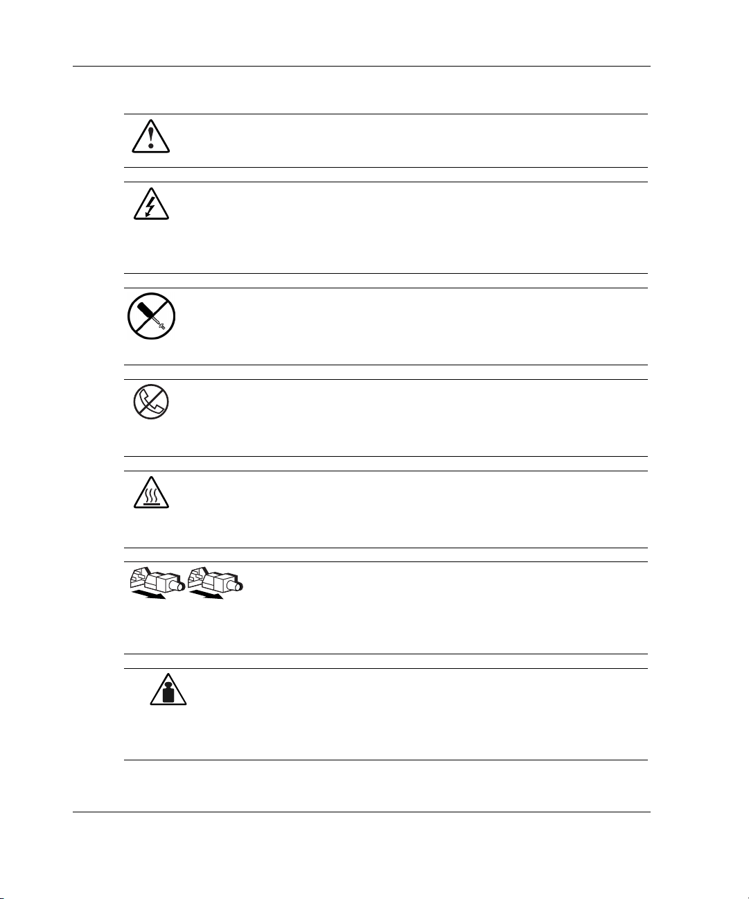
Symbols on Equipment
The following symbols may be placed on equipment to indicate the presence of
potentially hazardous conditions:
HP ProLiant ML350 Generation 3 Server Setup and Installation Guide ix
Page 10
About This Guide
Weight in kg
Weight in lb
WARNING: This symbol, in conjunction with any of the following symbols,
indicates the presence of a potential hazard. The potential for injury exists if
warnings are not observed. Consult your documentation for specific details.
This symbol indicates the presence of hazardous energy circuits or electric
shock hazards. Refer all servicing to qualified personnel.
WARNING: To reduce the risk of injury from electric shock hazards, do not
open this enclosure. Refer all maintenance, upgrades, and servicing to
qualified personnel.
This symbol indicates the presence of electric shock hazards. The area
contains no user or field serviceable parts. Do not open for any reason.
WARNING: To reduce the risk of injury from electric shock hazards, do not
open this enclosure
This symbol on an RJ-45 receptacle indicates a network interface connection.
WARNING: To reduce the risk of electric shock, fire, or damage to the
equipment, do not plug telephone or telecommunications connectors into this
receptacle.
This symbol indicates the presence of a hot surface or hot component. If this
surface is contacted, the potential for injury exists.
WARNING: To reduce the risk of injury from a hot component, allow the
surface to cool before touching.
These symbols, on power supplies or systems, indicate that the
equipment is supplied by multiple sources of power.
WARNING: To reduce the risk of injury from electric shock,
remove all power cords to completely disconnect power from the
system.
This symbol indicates that the component exceeds the recommended
weight for one individual to handle safely.
WARNING: To reduce the risk of personal injury or damage to the
equipment, observe local occupational health and safety requirements
and guidelines for manual material handling.
x HP ProLiant ML350 Generation 3 Server Setup and Installation Guide
Page 11
Rack Stability
WARNING: To reduce the risk of personal injury or damage to the equipment,
be sure that:
• The leveling jacks are extended to the floor.
• The full weight of the rack rests on the leveling jacks.
• The stabilizing feet are attached to the rack if it is a single-rack installation.
• The racks are coupled together in multiple-rack installations.
• Only one component is extended at a time. A rack may become unstable if
more than one component is extended for any reason.
Symbols in Text
These symbols may be found in the text of this guide. They have the following
meanings.
WARNING: Text set off in this manner indicates that failure to follow directions
in the warning could result in bodily harm or loss of life.
About This Guide
CAUTION: Text set off in this manner indicates that failure to follow directions could
result in damage to equipment or loss of information.
IMPORTANT: Text set off in this manner presents essential information to explain a concept
or complete a task.
NOTE: Text set off in this manner presents additional information to emphasize or supplement
important points of the main text.
HP ProLiant ML350 Generation 3 Server Setup and Installation Guide xi
Page 12

About This Guide
Related Documents
For additional information on the topics covered in this guide, refer to the following
documentation:
• HP ProLiant ML350 Generation 3 Server Maintenance and Service Guide
• HP ProLiant ML350 Generation 3 Server Quick Start poster
• ROM-Based Setup Utility User Guide
Getting Help
If you have a problem and have exhausted the information in this guide, you can get
further information and other help in the following locations.
Technical Support
In North America, call the HP Technical Support Phone Center at 1-800-652-6672.
This service is available 24 hours a day, 7 days a week. For continuous quality
improvement, calls may be recorded or monitored. Outside North America, call the
nearest HP Technical Support Phone Center. Telephone numbers for worldwide
Technical Support Centers are listed on the HP website, www.hp.com.
Be sure to have the following information available before you call HP:
• Technical support registration number (if applicable)
• Product serial number
• Product model name and number
• Applicable error messages
• Add-on boards or hardware
• Third-party hardware or software
• Operating system type and revision level
xii HP ProLiant ML350 Generation 3 Server Setup and Installation Guide
Page 13

HP Website
The HP website has information on this product as well as the latest drivers and flash
ROM images. You can access the HP website at www.hp.com.
Authorized Reseller
For the name of your nearest authorized reseller:
• In the United States, call 1-800-345-1518.
• In Canada, call 1-800-263-5868.
• Elsewhere, see the HP website for locations and telephone numbers.
Reader’s Comments
HP welcomes your comments on this guide. Please send your comments and
suggestions by e-mail to ServerDocumentation@hp.com.
About This Guide
HP ProLiant ML350 Generation 3 Server Setup and Installation Guide xiii
Page 14

1
Server Features
The HP ProLiant ML350 Generation 3 server delivers the latest performance
technology and availability features at an affordable price. Whether deployed in a
workgroup setting within a large corporation or as the primary server in a
small-to-medium business, this server is ideal for applications such as file and print
services, shared Internet access, and small databases. The server includes up to two
Intel® Xeon processors, PCI-X technology, Gigabit Ethernet and PC2100 DDR
memory for blazing performance. Plenty of headroom is also provided with six
hot-plug drive bays, two available media slots, and capacity for up to 8 GB of
memory. Its simple-to-service 5U design is optimized for both tower and rack
environments where it delivers tool-free access to system components, as well as
deployment and management tools designed to reduce ownership hassles.
HP ProLiant ML350 Generation 3 Server Setup and Installation Guide 1-1
Page 15

Server Features
Server features include:
•
Intel Xeon processor with Hyper-Threading technology and NetBurst
microarchitecture
•
Dual Processor capability
•
400/533-MHz front side bus (FSB)
•
PC2100 ECC Double Data Rate Synchronous DRAM (DDR SDRAM) DIMMs,
upgradeable to 8 GB, with optional interleaving capability
•
500-watt hot-plug power supply, optional 500-watt hot-plug redundant power
supply (1+1)
•
Capacity for six 1-inch hot-plug hard drives
•
Four removable media bays (two available) support optional tape drives,
non-hot-plug hard drives or 2-bay SCSI drive cage for two additional hot-plug
bays
•
Integrated dual channel Ultra3 SCSI
•
Integrated NC7760 Gigabit Server NIC Auto Switching Network Controller
•
Five PCI slots (four 64-bit 100-MHz PCI-X slots and one 32-bit 33-MHz PCI
slot)
•
IDE CD-ROM drive
•
Diskette drive
•
ATI Rage XL video controller with 8 MB RAM
•
Tower and rack form factors, tower-to-rack conversion kit
•
Insight Manager and SmartStart utilities
1-2 HP ProLiant ML350 Generation 3 Server Setup and Installation Guide
Page 16
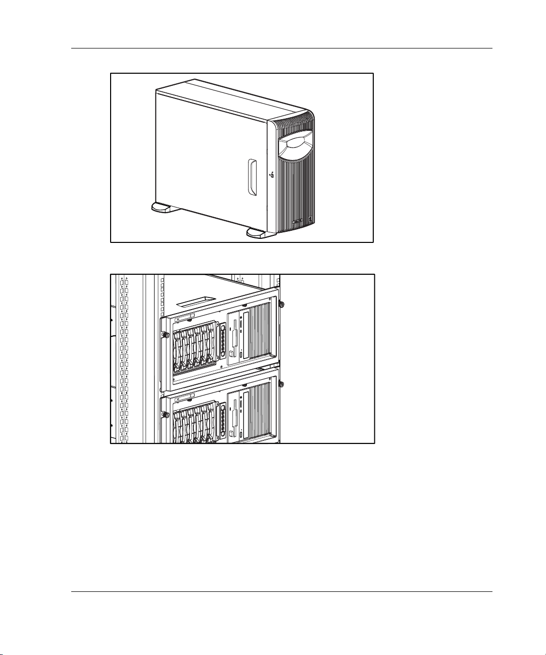
Figure 1-1: ProLiant ML350 Generation 3 tower server
Server Features
Figure 1-2: ProLiant ML350 Generation 3 rack server
(two shown)
HP ProLiant ML350 Generation 3 Server Setup and Installation Guide 1-3
Page 17
Server Features
Standard Hardware Features
The following hardware features are standard on this server, unless otherwise noted.
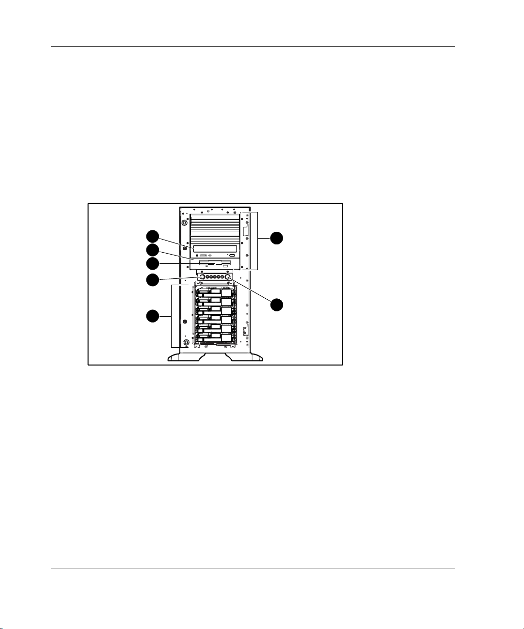
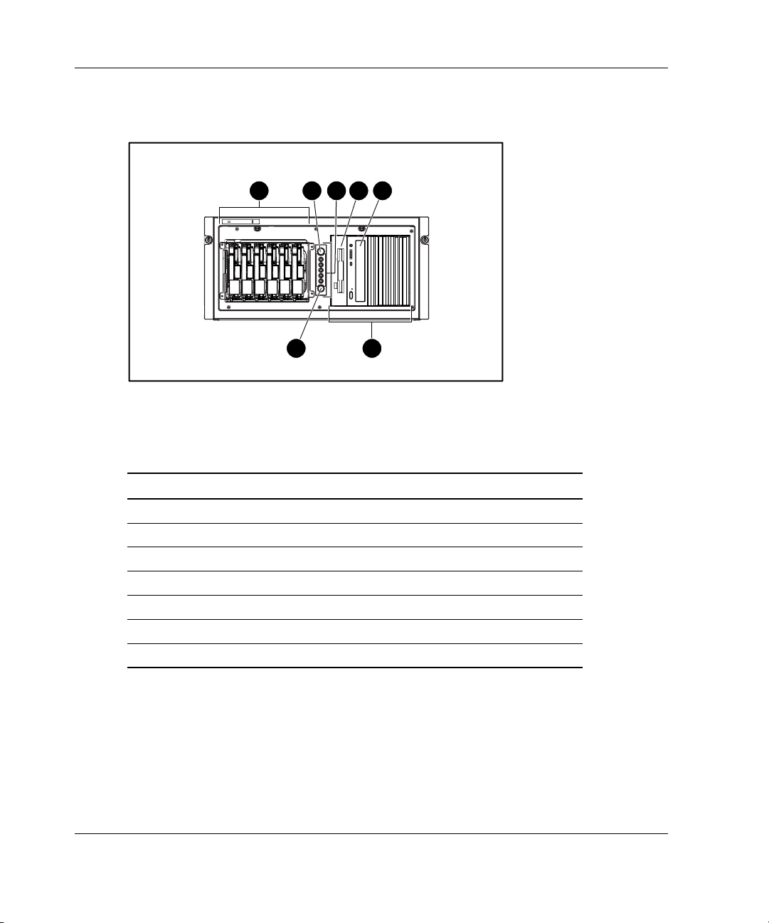
Tower Server Front Panel Components and Drive Bay Dimensions
This server supports a maximum of ten internal drives (four are intended for
removable media drives and six are for hot-plug hard drives). Figure 1-3 and
Table 1-1 show the server front panel components, as well as the drive dimensions.
7
6
5
4
3
1
2
Figure 1-3: Identifying front panel components with
bezel removed (tower)
1-4 HP ProLiant ML350 Generation 3 Server Setup and Installation Guide
Page 18

Server Features
Table 1-1: Tower Server Front Panel Components with Drive Bay
Dimensions
Item Component Dimensions
1 Removable media bays (4) 5.25 in x 1.60 in
2 Power button N/A
3 Hot-plug hard drive bays 3.5 in x 1.0 in
4 Unit ID button N/A
5 System status LEDs N/A
6 Diskette drive 3.5 in x 1.0 in
7 CD-ROM drive 5.25 in x 1.60 in
HP ProLiant ML350 Generation 3 Server Setup and Installation Guide 1-5
Page 19
Server Features
Rack Server Front Panel Components and Drive Bay Dimensions
3 6 7
54
2
1
Figure 1-4: Identifying front panel components (rack)
Table 1-2: Rack Server Front Panel Components with Drive Bay
Dimensions
Item Component Dimensions
1 Removable media bays (4) 5.25 in x 1.60 in
2 Power button N/A
3 Hot-plug hard drive bays 3.5 in x 1.0 in
4 Unit ID button N/A
5 System status LEDs N/A
6 Diskette drive 3.5 in x 1.0 in
7 CD-ROM drive 5.25 in x 1.60 in
1-6 HP ProLiant ML350 Generation 3 Server Setup and Installation Guide
Page 20
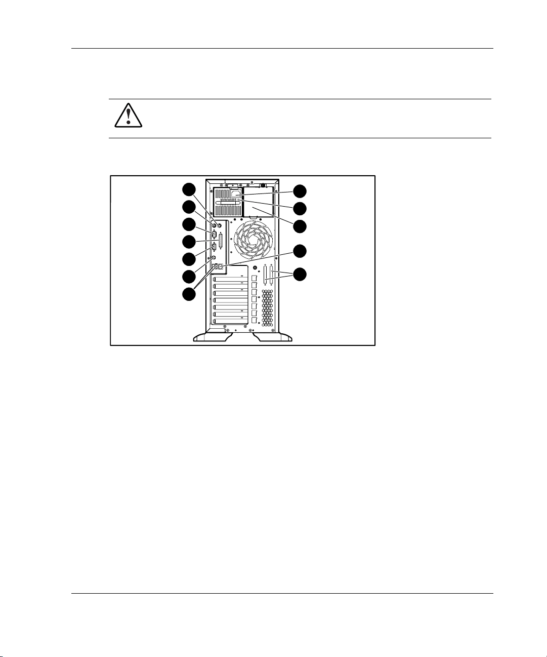
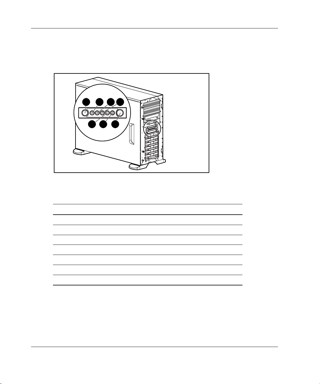
Tower Server Rear Panel Components
WARNING: This equipment is designed for connection to a grounded (earthed)
outlet. The grounding-type plug is an important safety feature. To reduce the
risk of electric shock or damage to your equipment, do not disable this feature.
Figure 1-5 and Table 1-3 show the connectors on the rear panel of the server.
Server Features
12
11
10
9
8
7
6
1
2
3
4
5
Figure 1-5: Identifying rear panel components
HP ProLiant ML350 Generation 3 Server Setup and Installation Guide 1-7
Page 21

Server Features
Table 1-3: Rear Panel Components
Item Component Item Component
1 Power cord connector 7 Unit ID LED/button
2 Power supply LED 8 Video connector
3 Optional hot-plug
4 RJ-45 Ethernet connector 10 Serial port connector
5 SCSI connector knockouts 11 Keyboard connector
6 USB port connectors (2) 12 Mouse connector
NOTE: Refer to Figure E-3 in Appendix E, “LED Indicators, Switches, and Jumpers” for an
illustration and explanation of the network controller LEDs which appear on the RJ-45 Ethernet
connector.
9 Parallel port connector
redundant power supply
bay
1-8 HP ProLiant ML350 Generation 3 Server Setup and Installation Guide
Page 22
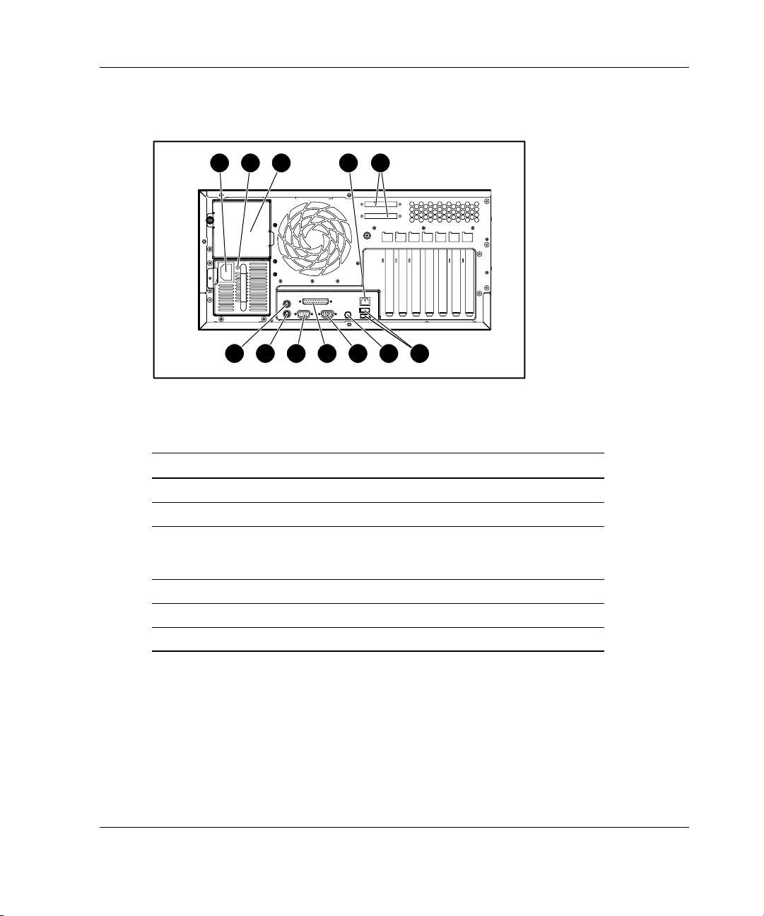
Rack Server Rear Panel Components
Server Features
1 32
12 11 6
10 9 8 7
4 5
Figure 1-6: Identifying rear panel components (rack)
Table 1-4: Rear Panel Components
Item Component Item Component
1 Power cord connector 7 Unit ID LED/button
2 Power supply LED 8 Video connector
3 Optional hot-plug
redundant power supply
bay
4 RJ-45 Ethernet connector 10 Serial port connector
5 SCSI connector knockouts 11 Keyboard connector
6 USB port connectors (2) 12 Mouse connector
9 Parallel port
connector
HP ProLiant ML350 Generation 3 Server Setup and Installation Guide 1-9
Page 23
Server Features
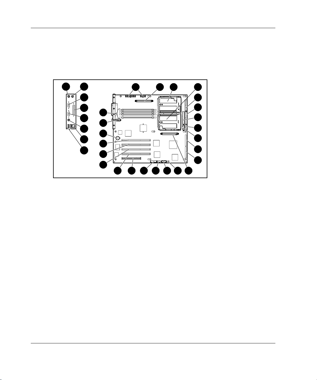
System Board Components
Figure 1-7 and Table 1-5 show the components and connectors on the system board
of the server.
32
31
30
29
28
27
26
25
2 31 4
24
2223
22
21
20
19
131415 121618 17
Figure 1-7: Identifying system board components
5
6
7
8
9
10
11
1-10 HP ProLiant ML350 Generation 3 Server Setup and Installation Guide
Page 24

Server Features
Table 1-5: System Board Components
Item Component Item Component
1 Power supply connectors 17 32-bit 33 MHz PCI slot
2 PPM socket 1 18 64-bit 100 MHz PCI-X
slot, bus 5
3 Processor socket 1 19 64-bit 100 MHz PCI-X
slot, bus 5
4 Processor socket 2 20
5 Diskette drive connector 21
6 Primary IDE connector
(ATAPI devices)
7 Secondary IDE connector
(ATAPI devices)
8 Power button connector 24 DIMM slots
9 I/O fan connector 25 USB port connectors (2)
10 Secondary SCSI connector 26 RJ-45 Ethernet connector
11 Primary SCSI connector 27 Unit ID LED/button
12 PPM socket 2 28 Video connector
13 Non-maskable Interrupt
Switch (NMI)
14 Remote Insight Lights-Out
II connector (30-pin)
15 System ID Switch 31 Mouse connector
16 System Configuration
Switch
22 Battery
23 CPU fan connector
29 Parallel port connector
30 Serial port connector
32 Keyboard connector
64-bit 100 MHz PCI-X
slot, bus 2
64-bit 100 MHz PCI-X
slot, bus 2
NOTE: For information on system board LEDs, refer to Appendix E, “LED Indicators,
Switches, and Jumpers.”
HP ProLiant ML350 Generation 3 Server Setup and Installation Guide 1-11
Page 25
Server Features
LEDs and Buttons
Figure 1-8 shows the LEDs and buttons on the front panel of the server.
1 2 3
5
4
6 7
Figure 1-8: Front panel LEDs and buttons
Table 1-6: Front Panel LEDs and Buttons
Item LED/Button
1 Unit ID button
2 Unit ID LED
3 Internal Health LED
4 External Health LED
5 NIC activity LED
6 Power LED
7 Power button
1-12 HP ProLiant ML350 Generation 3 Server Setup and Installation Guide
Page 26

Processors
•
Intel Xeon processor with Hyper-Threading technology
•
Integrated with a minimum of 512-KB level 2 Advanced Transfer Cache
•
400/533-MHz front side system bus
•
Dual-processor capability
System Memory
•
Advanced Error checking and correcting (AECC) for memory error detection and
correction
•
PC2100 ECC DDR memory DIMMs, upgradeable to 8 GB
•
Support for up to four PC2100 200/266-MHz registered ECC DDR DIMMs
•
DIMMs may be installed one at a time or in pairs
•
2 X 1 interleaving memory configuration option (with DIMMs installed in
identical pairs) or non-interleaving configuration supported
Server Features
Expansion Slots
•
Five expansion slots: four 64-bit PCI-X 100 MHz slots and one 32-bit PCI
33-MHz slot
•
3.3-volt compatible (5-volt compatible on the 32-bit PCI slot)
Storage Controller
•
Integrated dual-channel Ultra3 SCSI adapter on the PCI local bus. The controller
provides either two internal SCSI buses, two external SCSI buses, or one internal
and one external SCSI bus.
•
Optional controller boards for RAID support, controller duplexing or expanding
available storage capacity.
HP ProLiant ML350 Generation 3 Server Setup and Installation Guide 1-13
Page 27

Server Features
Network Interface Controller
•
Integrated NC7760 Gigabit Server Autoswitching Network Interface Controller
(NIC)
•
The Embedded NIC Port 1 PXE Support options allow the server to boot to the
network and attach to a PXE server with boot images. When enabled, the NIC
port is displayed in the initial program load (IPL) list.
Ports and Connectors
•
Serial
•
Parallel
•
Keyboard
•
Mouse
•
USB (2)
Power Supply
•
CE Mark-compliant 500-watt optionally redundant 1+1 hot-plug power supply
with power factor correction and auto switching
Video
•
Integrated ATI Rage XL Video Controller providing maximum resolution of
1280 x 1024 noninterlaced at 16.7 million colors
•
Supports SVGA, VGA, and EGA graphics resolution
•
8-MB SDRAM video memory
1-14 HP ProLiant ML350 Generation 3 Server Setup and Installation Guide
Page 28

Warranty
Consult the HP Customer Support Center or refer to the Limited Warranty Statement
included with the server for details. Certain restrictions and exclusions apply. For
additional warranty information, visit the HP website at
www.hp.com/servers/proliant/.
The HP Prefailure Warranty helps prevent unplanned shutdowns of the system by
allowing for the replacement of covered parts before they fail. The warranty covers
processors, memory, and hard drives. Insight Manager, included with the system,
must be installed for the HP Prefailure Warranty to be in effect.
When Insight Manager alerts you that a component may be eligible for Pre-Failure
Warranty replacement, follow the onscreen instructions or contact an HP authorized
service provider in your area. An amber status indicator on the Insight Manager
control panel signals that a component is in a prefailure condition and should be
replaced.
Server Features
HP ProLiant ML350 Generation 3 Server Setup and Installation Guide 1-15
Page 29

Server Features
Server Configuration and Management
This server offers an extensive set of features and optional tools to support effective
server management and configuration, including:
•
ROM-Based Setup Utility (RBSU) — performs a wide range of system
configuration activities
•
ROMPaq utility — allows the firmware (BIOS) to be upgraded by flashing the
system ROM and provides redundant ROM support in case of ROM corruption
•
SmartStart software — provides driver updates and assisted operating system
installation
•
Insight Manager management tool — monitors fault conditions, server
performance, security, and more
•
Diagnostics Utility — tests and verifies the operation of HP hardware
•
System Firmware Update — enables system administrators to efficiently update
system firmware, either directly on remote servers via the network, or locally via
Web downloads
•
Automatic Server Recovery (ASR) — automatically resets a server that has not
responded in a select amount of time or has reached a dangerous temperature
•
Survey Utility — allows you to keep a historical record of server hardware and
software changes in a single configuration history file
•
Power-On Self-Test — checks firmware and assemblies to ensure that the system
is properly functioning
•
Pre-boot Execution Environment (PXE) — support for installing and configuring
operating systems remotely
Refer to Chapter 5, “Server Configuration and Utilities,” for detailed information on
each of these utilities.
1-16 HP ProLiant ML350 Generation 3 Server Setup and Installation Guide
Page 30

Security
Security features include:
•
Setup Password
•
Power-on Password
Diskette Drive Control
•
Diskette Write Control
•
Diskette Boot Override
•
Serial Interface Control
•
CD Boot Override
•
Parallel Interface Control
•
Power Switch Protection
•
Bezel Lock
•
Most security features are established through RBSU. For detailed information on
RBSU, refer to Chapter 5, “Server Configuration and Utilities,” or refer to the
ROM-Based Setup Utility User Guide. For additional information concerning server
security features, refer to the SmartStart CD included in the shipping box.
Server Features
HP ProLiant ML350 Generation 3 Server Setup and Installation Guide 1-17
Page 31
2
Overview of Server Installation
The following instructions are provided as an overview for first-time installation of
the HP ProLiant ML350 Generation 3 server.
WARNING: To reduce the risk of electric shock or damage to the equipment:
• Do not disable the power cord grounding plug. The grounding plug is an
important safety feature.
• Plug the power cord into a grounded (earthed) electrical outlet that is
easily accessible at all times.
• Disconnect power from the server by unplugging the power cord from
either the electrical outlet or the server.
• Do not place anything on power cords or cables. Arrange them so that no
one can accidentally step on or trip over them. Do not pull on a cord or
cable. When unplugging from the electrical outlet, grasp the cord by the
plug.
CAUTION: Electrostatic discharge (ESD) can damage electronic components. Be
sure that you are properly grounded (earthed) before beginning any installation
procedure. Refer to Appendix B, “Electrostatic Discharge (ESD),” for more
information.
HP ProLiant ML350 Generation 3 Server Setup and Installation Guide 2-1
Page 32

Overview of Server Installation
Planning the Server Installation
To ensure maximum performance and availability from the server, plan your
operating environment before beginning server installation.
This section discusses site preparation and guidelines for the rack and tower server
installation including:
•
Rack planning resources
•
Rack warnings
•
Server warnings and cautions
•
Rack server shipping contents
•
Tower server shipping contents
•
Site environment
2-2 HP ProLiant ML350 Generation 3 Server Setup and Installation Guide
Page 33

Rack Planning Resources
The following resource information is available for rack designs and products.
The Rack Builder Pro Configuration Tool and Rack Products Documentation is
available on the website:
www.compaq.com/rackbuilder/
The rack resource kit with Rack Resource CD ships with all Compaq branded racks.
A summary of the content of each CD follows:
•
Rack Builder Pro Configuration Tool
This information enables you to simulate potential Compaq branded rack
configurations based on your input. Rack Builder Pro provides the following
information:
— Graphical preview of properly configured racks
— Site planning data, including power requirements, cooling mandates, and
physical specifications
— Ordering information, including required components, part numbers, and
appropriate quantities
Overview of Server Installation
•
Installing Rack Products video
This video provides a visual overview of operations required for configuring a
Compaq branded rack with rack-mountable components. It also provides the
following important configuration steps:
— Planning the site
— Installing rack servers and rack options
— Cabling servers in a rack
— Coupling multiple racks
•
Rack Products Documentation CD
HP ProLiant ML350 Generation 3 Server Setup and Installation Guide 2-3
Page 34
Overview of Server Installation
The resource information on this CD enables you to view, search, and print
documentation for Compaq branded racks and rack options. It also helps you set
up and optimize your new Compaq branded rack in a manner that best fits your
environment.
Rack Warnings and Cautions
Before installing your rack, carefully review the following warnings and cautions:
WARNING: To reduce the risk of personal injury or equipment damage, always
be sure that the rack is adequately stabilized before extending a component
outside the rack. A rack may become unstable if more than one component is
extended for any reason. Extend only one component at a time.
WARNING: To reduce the risk of personal injury or equipment damage, be
sure that:
• The leveling jacks are extended to the floor.
• The full weight of the rack rests on the leveling jacks.
• The stabilizers are attached to the rack for single-rack installation.
• The racks are installed together in multiple-rack installations.
WARNING: To reduce the risk of personal injury or equipment damage, at
least two people are needed to safely unload the rack from the pallet. An empty
42U rack can weigh as much as 115 kg (253 lb), can stand more than 2.1 m
(7 ft) tall, and may become unstable when being moved on its casters.
Never stand in front of the rack when it is rolling down the ramp from the
pallet. Always handle the rack from both sides.
CAUTION: Always begin by mounting the heaviest item on the bottom of the rack.
Continue to populate the rack from the bottom to the top.
2-4 HP ProLiant ML350 Generation 3 Server Setup and Installation Guide
Page 35

Server Warnings and Cautions
Before installing the server, carefully review the following warnings and cautions:
WARNING: This server weighs 27.24 kg (60 lb) with no drives installed. To
reduce the risk of personal injury or damage to the equipment:
• Observe local occupational health and safety requirements and guidelines
for manual material handling.
• Get help to lift and stabilize the product during installation or removal,
especially when the product is not fastened to the rails.
• Use caution when installing the product in or removing the product from
the rack; the product is unstable when not fastened to the rails.
WARNING: When the server weighs more than 22.7 kg (50.4 lb), at least two
people must lift the server into the rack together. If the unit is loaded into the
rack above chest level, a third person must assist in aligning the rails while the
other two support the unit.
WARNING: To reduce the risk of personal injury from hot surfaces, enable the
drives and the internal system components to cool before touching them.
Overview of Server Installation
WARNING: To reduce the risk of electrical shock or damage to the equipment,
only enter or service specific parts of the server as instructed in the user
documentation.
WARNING: Setting the server Power On/Standby button to the off position
removes power from most areas of the server. This process may take
30 seconds. Portions of the power supply and some internal circuitry remain
active until the AC power cord is disconnected.
To remove power completely, disconnect the power cord. If the server has
multiple power supplies installed, unplug all power cords to completely
remove power from the system.
WARNING: When performing non-hot-plug operations, you must power down
the system. However, it may be necessary to leave the server powered up
when performing other operations, such as hot-plug installations or
troubleshooting.
HP ProLiant ML350 Generation 3 Server Setup and Installation Guide 2-5
Page 36

Overview of Server Installation
CAUTION: Protect the server from power fluctuations and temporary interruptions
with a regulating UPS device. This device protects the hardware from damage
caused by power surges and voltage spikes and keeps the system in operation
during a power failure.
CAUTION: Do not operate the server for long periods without the access panel.
Operating the server without the access panel results in improper airflow and
improper cooling that can lead to thermal damage.
Rack Server Shipping Carton Contents
Unpack the server box, hardware, and documentation according to the instructions
and illustrations printed on the shipping carton. All of the rack-mounting hardware
necessary for installation of the rack server into a Compaq branded rack is included
with the server.
The contents of the rack server box provided with the server include the following:
•
HP ProLiant ML350 Generation 3 server
•
Power cord
•
Hardware documentation, reference information, and software products
•
Rack-mounting hardware
Before beginning rack installation, be sure that you have all of the components
shown in the following illustration.
2-6 HP ProLiant ML350 Generation 3 Server Setup and Installation Guide
Page 37

Overview of Server Installation
1
6
2
ProLiant ML350 Tower
to Rack Install Guide
3
5
4
Figure 2-1: Rack-mounting hardware
Table 2-1: Rack Mounting Hardware
Item Description Item Description
1 Rack template 4 Torx screws
2 Documentation 5 Mounting bracket slide
assemblies and
component rails
3 Cable management arm
6 Cable management arm
bracket
HP ProLiant ML350 Generation 3 Server Setup and Installation Guide 2-7
Page 38

Overview of Server Installation
Tower Server Shipping Carton Contents
Unpack the server, keyboard, and cables according to the instructions and
illustrations printed on the shipping carton.
The contents of the tower server carton include:
•
HP ProLiant ML350 Generation 3 server
•
Power cord
•
Keyboard
•
Mouse
•
Hardware documentation, reference information, and software products
Site Environment
Refer to the “Rack Environment” section later in this chapter and to Appendix F,
“Specifications,” for detailed power and environmental site requirements.
2-8 HP ProLiant ML350 Generation 3 Server Setup and Installation Guide
Page 39
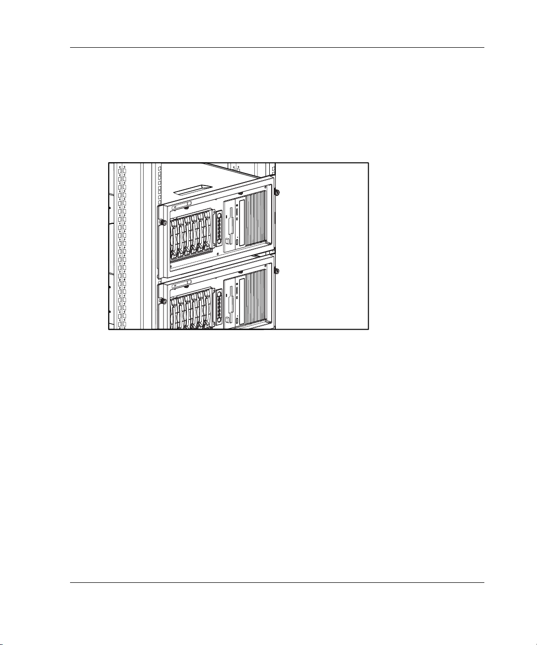
Installing the Rack Server
The rack model comes ready for immediate installation. This section provides
environmental information required for the installation of a rack-mounted server.
Figure 2-2 shows the server installed in a rack configuration.
Figure 2-2: HP ProLiant ML350 Generation 3 servers
installed in a rack
Overview of Server Installation
Tower-to-Rack Option
A rack conversion option kit is available for customers who want to convert a tower
server to a rack server.
To purchase the rack conversion kit (Part Number 290683-B21), contact your local
HP authorized reseller or order direct from HP.
A selection of racks for the server can be purchased through your HP authorized
reseller or direct from HP at
HP ProLiant ML350 Generation 3 Server Setup and Installation Guide 2-9
www.hp.com/servers/proliant/.
Page 40

Overview of Server Installation
Rack Environment
To allow for servicing and adequate airflow, observe the following spatial and
environmental requirements when selecting a site for your rack-mounted server:
•
Select a sturdy, level installation site that includes dedicated and properly
grounded (earthed) circuits, air conditioning and electrostatic discharge (ESD)
protection.
•
Leave a minimum clearance of 63.5 cm (25.0 inches) in front of the rack.
•
Leave a minimum clearance of 76.2 cm (30.0 inches) behind the rack.
•
Leave a minimum clearance of 121.9 cm (48.0 inches) from the back of the rack
to the back of another rack or row of racks.
HP servers draw in cool air through the front door of the rack and expel warm air
through the rear door. Therefore, the front door must be adequately ventilated to
allow ambient room air to enter the cabinet, and the rear door must be adequately
ventilated to allow the warm air to escape from the cabinet.
IMPORTANT: Do not block the ventilation openings.
When there is any vertical space in the rack not filled by a server or rack component,
the gaps between the components cause changes in airflow through the rack and
across the servers. Cover all gaps with blanking panels to maintain proper airflow.
CAUTION: Always use blanking panels to fill empty vertical spaces in the rack. This
arrangement ensures proper airflow. Using a rack without blanking panels results in
improper cooling that can lead to thermal damage.
Compaq branded 9000 and 10000 Series racks provide proper server cooling from
flow-through perforations in the front and rear doors that provide 64 percent open
area for ventilation. Refer to the rack documentation provided with Compaq branded
7000 Series racks for guidelines on meeting airflow requirements.
CAUTION: When using a Compaq branded 7000 Series rack, you must install the
high-airflow rack door insert [Part Number 327281-B21 (42U) and Part Number
157847-B21 (22U)] to provide proper front-to-back airflow and cooling to prevent
damage to the equipment.
2-10 HP ProLiant ML350 Generation 3 Server Setup and Installation Guide
Page 41

CAUTION: If a third-party rack is used, observe the following additional
requirements to ensure adequate airflow and to prevent damage to the equipment:
• Front and rear doors: If the 42U server rack includes closing front and rear
doors, ensure 5,350 sq cm (830 square inches) of holes are evenly distributed
from top to bottom to permit adequate airflow (equivalent to the required 64
percent open area for ventilation).
• Side: The clearance between the installed rack component and the side panels
of the rack must be a minimum of 7 cm (2.75 inches).
Locating Materials
Locate the following materials that were shipped with the server:
•
Keyboard (not included with the rack model)
•
Mouse (not included with the rack model)
•
Power cord
•
Documentation and software packs inside the shipping box
Overview of Server Installation
•
Rack-mounting hardware (rack model only)
In addition to the supplied items, you may need:
•
Torx T-15 screwdriver
•
Hardware options
•
Ethernet cable
•
Operating system or application software
•
Uninterruptible Power Supply (UPS) or Power Distribution Unit (PDU)
•
Monitor
HP ProLiant ML350 Generation 3 Server Setup and Installation Guide 2-11
Page 42

Overview of Server Installation
Rack Installation Procedures
Install any optional hardware components before installing and powering up the
server for the first time. Refer to Chapter 3, “Hardware Options Installation,” for
instructions on installing PCI expansion boards, memory, processors, hot-plug
expansion boards, and other major hardware options.
The rack installation sequence for this server includes:
•
Installing rack-mountable-specific server chassis components
•
Securing the mounting hardware to the rack
•
Installing the server into the rack
•
Installing the cable management arm
•
Cabling the server
•
Powering up the server
•
Installing an operating system
•
Configuring the server
•
Registering the server
Installing Rack-Mountable-Specific Server Chassis
Components
You must configure the server per the following before installing in the rack:
•
System Configuration Switch setting (factory pre-set for rack model servers)
•
Component rails
•
Cable management arm bracket
2-12 HP ProLiant ML350 Generation 3 Server Setup and Installation Guide
Page 43
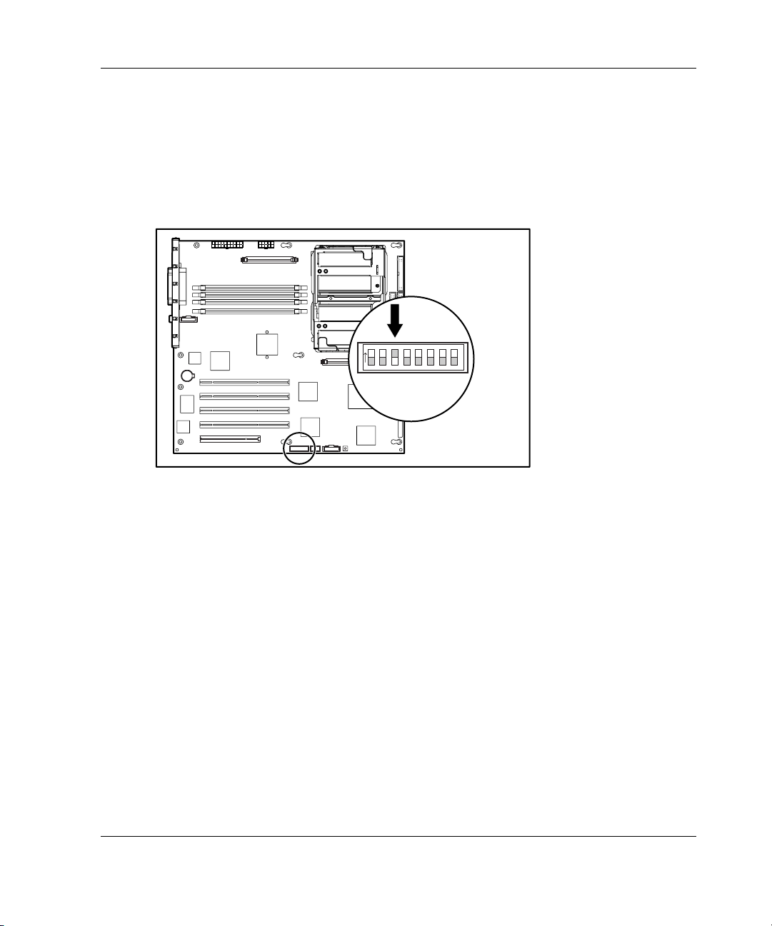
System Configuration Switch Setting
Switch 3 on the system configuration switch is the rack configuration switch. This
will be pre-set at the factory to the on position for rack model servers and does not
require any action at the install site. Figure 2-3 shows the system configuration
switch setting with the factory pre-set positions.
on
Overview of Server Installation
1 234
5 678
Figure 2-3: System configuration switch setting
HP ProLiant ML350 Generation 3 Server Setup and Installation Guide 2-13
Page 44

Overview of Server Installation
Installing Component Rails on the Server
Your conversion kit includes a set of adjustable-length slide rail assemblies. A slide
rail assembly consists of:
• • A component rail that is mounted to the server
A slide rail, which is the mechanism that accepts the component rail and is
mounted to the rail mounting bracket
The component rails are installed into the slide when shipped and must be removed
before the component rails can be mounted to the server.
To remove the component rail from the slide:
1. Extend the component rail from the slide until the component rail release latch
clicks (1).
2. Holding down the latch (2), pull the component rail out of the slide. You may
need to give the rail a sharp tug to disengage it from the slide.
2
1
Figure 2-4: Removing the component rail from the slide
2-14 HP ProLiant ML350 Generation 3 Server Setup and Installation Guide
Page 45

Overview of Server Installation
To install the component rails onto the server:
1. Line up the mounting holes in the component rail with the chassis mounting
spools on the server (1).
2. Place the component rail on the server and slide it towards the back of the chassis
until the mounting spool locks engage (2).
3. Repeat this procedure on the other side of the server using the second component
rail.
2
1
Figure 2-5: Installing a component rail onto the server
HP ProLiant ML350 Generation 3 Server Setup and Installation Guide 2-15
Page 46
Overview of Server Installation
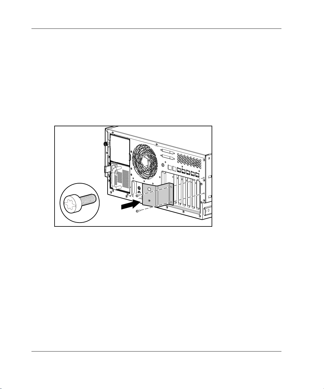
Installing the Cable Management Arm Bracket
The cable management arm bracket allows you to secure the cable management arm
to the server and to the rear frame of the rack.
To install the cable management arm bracket to the server:
1. Locate the two bracket screws included with your kit.
2. Using a Torx T-15 screwdriver and the two bracket screws, secure the cable
management arm bracket to the back of the server.
Figure 2-6: Securing the cable management arm bracket
to the server
2-16 HP ProLiant ML350 Generation 3 Server Setup and Installation Guide
Page 47

Overview of Server Installation
Securing the Mounting Hardware to the Rack
To secure the mounting brackets and slide rail assemblies:
•
Mark the server rack position with the template.
•
Insert cage nuts into the rack frame.
•
Install the mounting bracket slide assembly onto the rack.
Marking with the Template
A template is provided to mark the rack for cage nut and mounting bracket positions.
Starting at the bottom of the rack or at the top of a previously mounted component:
1. With the two push tabs, place the template in the desired location. Make sure that
you match the hole pattern printed on the template with the actual holes on the
rack vertical rails.
Template
Figure 2-7: Using the template
2. Use a pencil to mark locations indicated on the template for cage nuts and slide
assembly mounting brackets.
HP ProLiant ML350 Generation 3 Server Setup and Installation Guide 2-17
Page 48
Overview of Server Installation
3. After marking the front of the rack, flip the template over, then repeat the
procedure on the back rails of the rack. Also mark the top of the template on the
rack to help align the next components.
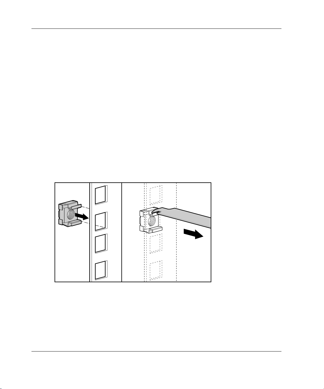
Inserting Cage Nuts into the Rack Frame
Use the fitting tool to insert cage nuts on the inside of the rails at the marked
locations. Make sure to install two cage nuts at the front of the rack. These will be
used to secure the server chassis to the rack using the two front panel thumbscrews
(refer to Figure 2-15).
NOTE: The cage nuts and fitting tool are included in the hardware kit supplied with the rack.
1. On the inside of the rail, hook one of the lips of the cage nut through the square
rail hole.
2. Insert the tip of the fitting tool through the other side of the hole, then hook the
opposite lip of the cage nut.
Figure 2-8: Inserting cage nuts into the rack frame
3. Using the fitting tool as a lever, slide the cage nut lip into position.
4. Repeat this procedure for each cage nut.
2-18 HP ProLiant ML350 Generation 3 Server Setup and Installation Guide
Page 49

Installing the Mounting Bracket Slide Assembly
The mounting bracket slide assemblies are labeled with the correct positioning in the
rack. The labels will read “Front-Left,” “Back-Left,”,“Front-Right,” and
“Back-Right.”
To install the mounting bracket slide assembly:
1. Select the appropriate slide assembly, matching the position label on the slide
with the side being installed. The slide assembly as shown in Figure 2-9 would
be labeled “Front – Right” on the inside front surface.
2. Position the mounting bracket according to the pencil marks made with the
template earlier, extending the slide assembly to fit the rack (1).
3. Secure the front of the mounting bracket first, inserting the mounting tabs into
position and pushing down until the locking latch engages (2).
4. Secure the back of the mounting bracket (would be marked “Back – Right” in
Figure 2-9 example) by inserting the mounting tabs into the rack and pushing
down until the locking latch engages (3).
NOTE: Be sure that the mounting bracket is level from front to back.
Overview of Server Installation
2
1
3
Figure 2-9: Securing the mounting bracket slide
assembly to the rack
HP ProLiant ML350 Generation 3 Server Setup and Installation Guide 2-19
Page 50
Overview of Server Installation
5. Repeat this process for the other mounting bracket slide assembly.
Installing the Server into Round-Hole Racks
This server can be installed in round-hole racks. The following sections provide
details for converting the mounting bracket slide assembly to the round-hole
configuration and installing into round-hole racks.
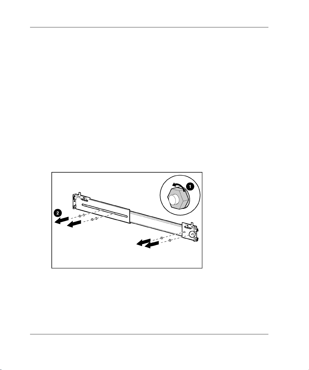
Converting the Mounting Bracket Slide Assembly for Round-Hole Racks
To convert the slide assembly for round-hole racks:
1. Loosen the nuts and washers (1) and remove them from the original rail
brackets (2).
Figure 2-10: Removing the nuts and washers
2-20 HP ProLiant ML350 Generation 3 Server Setup and Installation Guide
Page 51

Overview of Server Installation
2. Remove the original rail brackets from the slide assembly.
Figure 2-11: Removing the brackets from the slide
assembly
3. Install the round-hole conversion brackets on the slide rail assembly.
Figure 2-12: Installing the round-hole conversion
brackets
4. Reinstall the hardware removed in step 1.
HP ProLiant ML350 Generation 3 Server Setup and Installation Guide 2-21
Page 52
Overview of Server Installation
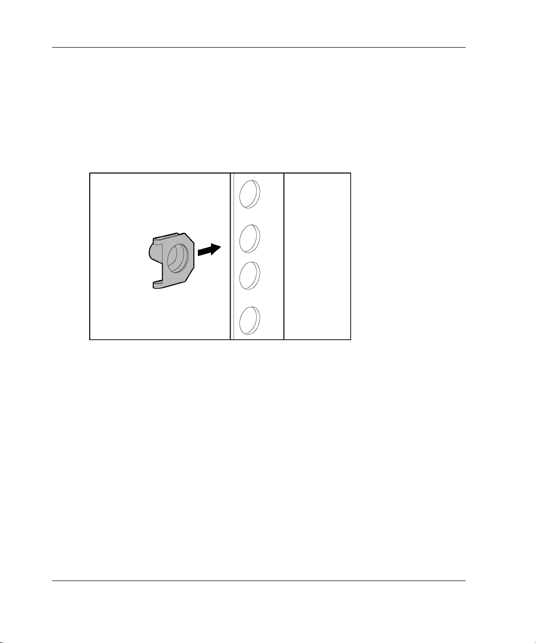
Installing Round-Hole Rack Cage Nuts
The round-hole rack cage nuts can be installed without special tools. Make sure to
install two cage nuts at the front of the rack at the locations marked in the section
“Marking with the Template.”
NOTE: The cage nuts are included in the hardware kit supplied with the rack.
Figure 2-13: Installing round-hole rack cage nuts
Installing the Mounting Bracket Slide Assembly in Round-Hole Racks
The mounting bracket slide assemblies are labeled with the correct positioning in the
rack. The labels will read “Front – Left,” “Back – Left,” “Front – Right,” and
“Back – Right.”
To install the mounting bracket slide assembly:
1. Select the appropriate slide assembly, matching the position label on the slide
with the side being installed.
2-22 HP ProLiant ML350 Generation 3 Server Setup and Installation Guide
Page 53

Overview of Server Installation
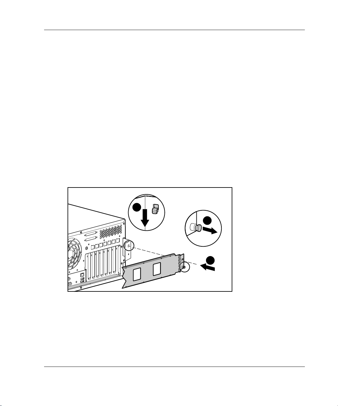
2. Position the slide assembly according to the pencil marks made with the template
earlier, extending the slide assembly to fit the rack (1).
3. Secure the front of the mounting bracket first. Insert the round-hole rack bracket
mounting screws and nuts into position and tighten (2).
Figure 2-14: Securing the round-hole rack bracket slide
assembly
4. Secure the back of the slide assembly. Insert the round-hole rack bracket
mounting screws and nuts into position and tighten.
IMPORTANT: Be sure that the mounting bracket is level from front to back.
Repeat this process for the other mounting bracket slide assembly.
Installing the Server into the Rack
To install the server into the rack:
WARNING: To reduce the risk of personal injury or damage to the
equipment, a minimum of two people MUST lift the server into the rack. If
the unit is loaded above chest level, a third person must assist in aligning
the rails while the other two support the unit.
HP ProLiant ML350 Generation 3 Server Setup and Installation Guide 2-23
Page 54

Overview of Server Installation
NOTE: The server can be installed with the mounting bracket slide assembly in either closed
or extended position.
1. Carefully align the server component rails with the rack slide rails, then slide the
server all the way into the rack (2) until the server rail locks engage (1).
CAUTION: Be sure to keep the server parallel to the floor when sliding the
server component rails into the mounting bracket slide rails. Tilting the server up
or down can result in damage to the rails.
IMPORTANT: The first time you slide the server into the rack, you may have to apply
some pressure. After the first time, the ball bearings in the slide should move easily.
2. Slide the server in and out of the rack several times to properly align the slide
mount rails.
3. Secure the server by screwing the front panel thumbscrews into the rack (3).
WARNING: To reduce the risk of personal injury, be careful when
sliding the server into the rack. The slide rails could pinch your
fingertips.
3
1
2
Figure 2-15: Loading the server into the rack
2-24 HP ProLiant ML350 Generation 3 Server Setup and Installation Guide
Page 55
Installing the Cable Management Arm
The cable management arm secures to the cable management arm bracket that was
previously installed. See “Installing the Cable Management Arm Bracket” section
earlier in this chapter. All cables running to and from the server are secured to this
arm. The cable management arm allows the cables to swing out of the way when the
server is accessed.
To install the cable management arm:
1. Slide the server into the rack. See “Installing the Server into the Rack” earlier in
this chapter.
2. Secure the server end of the cable management arm (1) to the cable management
arm bracket (located on the server) by pulling out on the spring-loaded
fastener (2), inserting the locking tab (3) into the cable management arm bracket,
releasing the spring-loaded fastener, and pushing down until the spring-loaded
fastener engages.
3
Overview of Server Installation
2
1
Figure 2-16: Securing the cable management arm to the
bracket
3. Align the other end of the cable management arm with the inside of the left rear
rack frame mounting bracket (mounted on rear of left side slide assembly).
HP ProLiant ML350 Generation 3 Server Setup and Installation Guide 2-25
Page 56

Overview of Server Installation
4. Secure the cable management arm to the rear rack frame mounting bracket by
pulling out on the spring-loaded fastener (1), inserting the two locking tabs (2),
releasing the spring-loaded fastener, and pressing in towards the server chassis
until the spring-loaded fastener engages.
Figure 2-17: Securing the cable management arm to the
mounting bracket
2
1
2-26 HP ProLiant ML350 Generation 3 Server Setup and Installation Guide
Page 57

Cabling the Server
After the cable management arm is installed, cable the server by following these
procedures:
1. Plug all external cables into the server.
2. If you installed a switchbox into the rack, route the CPU-to-switchbox cables to
the switchbox.
3. Bundle all of the cables, including the power cable, then secure them to the cable
management arm using the Velcro strips.
Overview of Server Installation
Figure 2-18: Routing and securing the cables
4. Extend the bundled cables down the rack cable channel.
HP ProLiant ML350 Generation 3 Server Setup and Installation Guide 2-27
Page 58
Overview of Server Installation
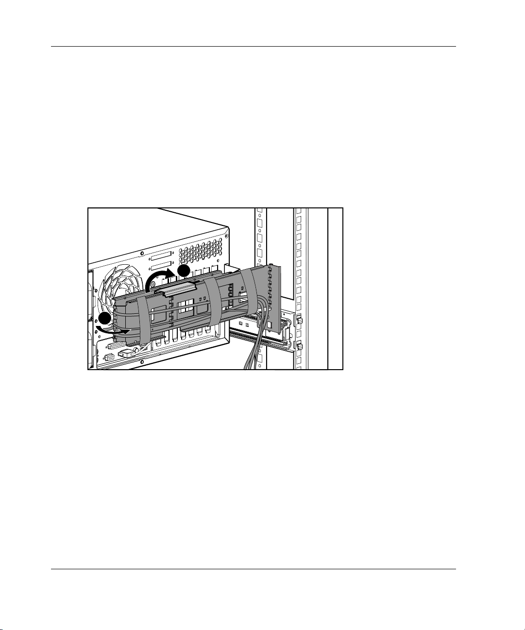
Accessing the Redundant Power Supply Bay
The cable management arm comes with a center joint to allow easy access to the
power supply bays without having to remove the arm.
To service the power supply bays:
1. Lift up the center joint locking bracket located near the center of the outside
cable management arm piece (1).
2. Swing the cable management arm back away from the server chassis (2).
1
2
Figure 2-19: Swinging the Cable Management Arm away
from the chassis
3. After completing the desired service function, return the cable management arm
to its locked position by reversing steps 1 and 2.
Powering Up the Server
Power up the server after the peripheral and power cords are connected to the server.
2-28 HP ProLiant ML350 Generation 3 Server Setup and Installation Guide
Page 59
Overview of Server Installation
WARNING: To reduce the risk of electrical shock or damage to the equipment:
• Do not disable the power cord grounding plug. The grounding plug is an
important safety feature.
• Plug the power cord into a grounded (earthed) electrical outlet that is
easily accessible at all times.
• Unplug the power cord from each power supply to disconnect power to the
equipment.
• Do not route the power cord where it can be walked on or pinched by
items placed against it. Pay particular attention to the plug, electrical
outlet, and the point where the cord exits from the server.
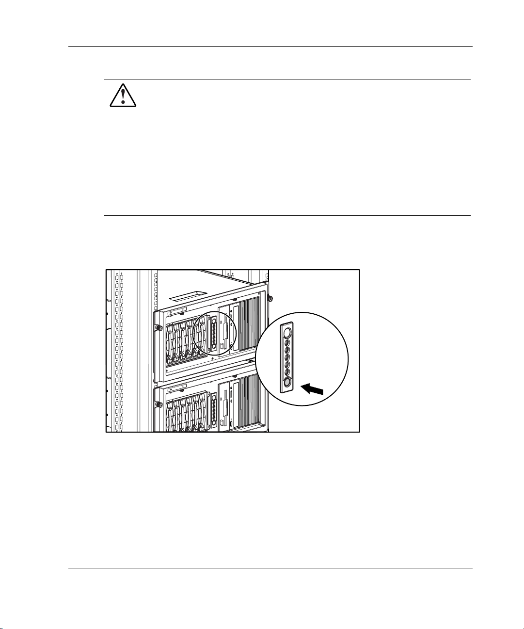
To power up the server:
1. Press the Power On/Standby button to power up the server.
Figure 2-20: Powering up the rack server
HP ProLiant ML350 Generation 3 Server Setup and Installation Guide 2-29
Page 60

Overview of Server Installation
2. Observe the front panel LEDs to verify a successful power-on sequence. For a
detailed explanation of all system LEDs, refer to Appendix E, “LED Indicators,
Switches, and Jumpers.”
When the server powers on for the first time, the server performs a POST and
launches RBSU. After selecting initial system settings, install your operating system
and perform additional configuration tasks. For additional information about
configuring the server with RBSU, refer to the ROM-Based Setup Utility User Guide
and to Chapter 5, “Server Configuration and Utilities.”
Factory-Installed Operating Systems
If you ordered the server with a preinstalled operating system, everything required to
install your operating system is already on the server. Refer to the steps provided in
the Factory-Installed Operating System Software User Guide for more information
on using your operating system.
1. Review and follow the guidelines and procedures in the previous sections of this
chapter.
2. Connect the cables: keyboard, mouse, monitor, network, and power. Refer to the
section for tower server or rack server rear panel components in Chapter 1,
“Server Features.”
WARNING: To reduce the risk of electric shock or fire, do not plug
telecommunications/telephone connectors into the network interface
controller (NIC) receptacle.
3. Locate the key and unlock the front bezel if necessary.
NOTE: A key hook is located inside the front bezel above the keylock latch. For your
convenience, you may use the key hook to store the key when it is not needed.
2-30 HP ProLiant ML350 Generation 3 Server Setup and Installation Guide
Page 61

Overview of Server Installation
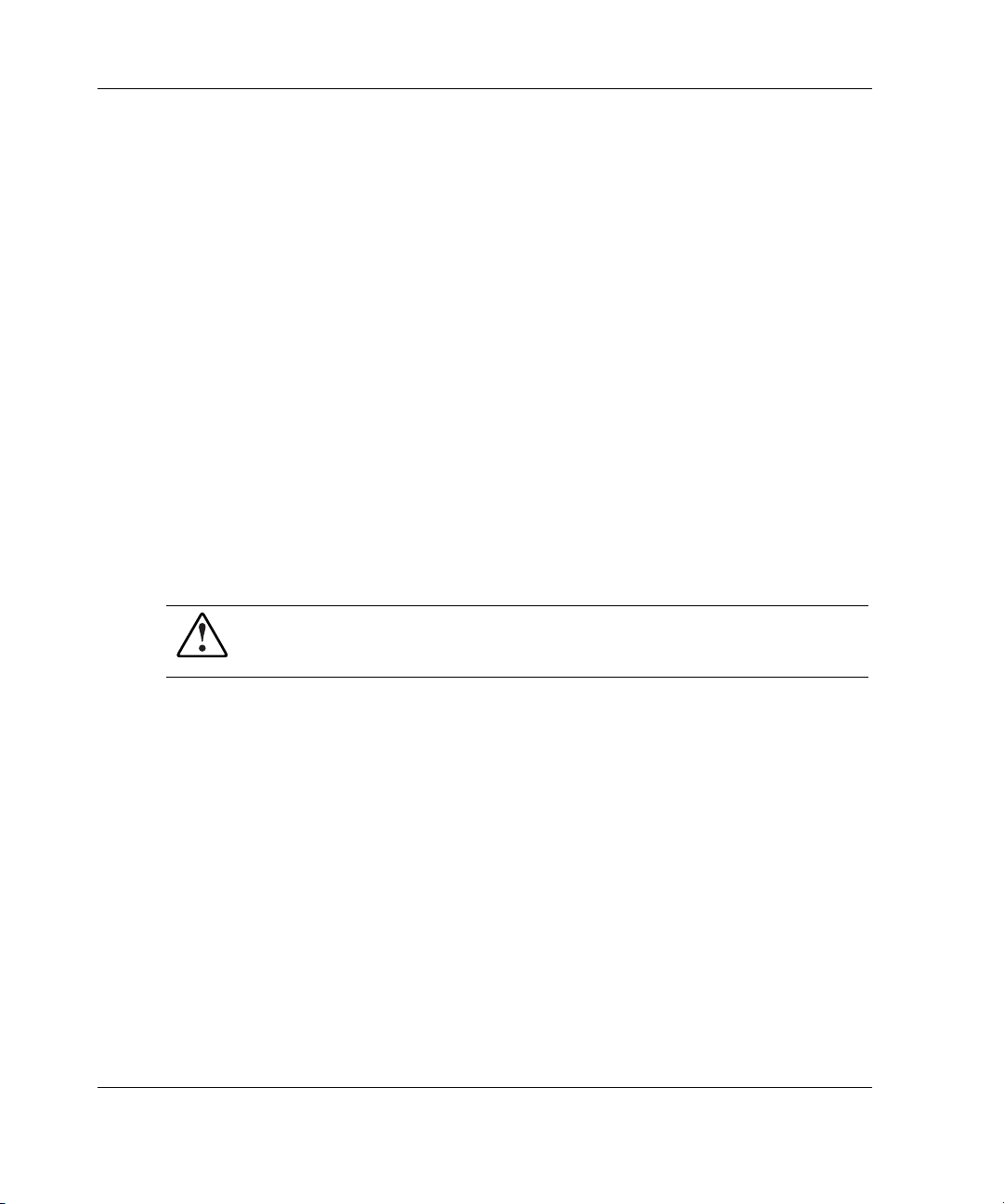
4. Power up the server by opening the front bezel and pressing the Power
On/Standby button on the front of the server (1).
1
2
Figure 2-21: Powering up the server (bezel removed for
clarity)
5. Follow the onscreen instructions to complete the preinstalled operating system
initialization process. After initialization is complete, the server automatically
goes through Power-On Self-Test (POST).
6. To manage the server, install Insight Manager, found on the Management CD.
For Management CD initialization procedures, refer to the Server Setup and
Management pack shipped with the server.
IMPORTANT: You must install and use Insight Manager to benefit from the Pre-Failure
Warranties on processors, hard drives, and memory modules.
7. After verifying your specific server configuration, back up the system
configuration. Refer to the SmartStart CD for further information on backing up
your system configuration.
8. Install any additional hardware. Refer to Chapter 3, “Hardware Options
Installation,” or the option kits, for detailed instructions on installing internal
hardware.
9. Install any application software.
HP ProLiant ML350 Generation 3 Server Setup and Installation Guide 2-31
Page 62
Overview of Server Installation
10. Register the server. Refer to the “Server Registration” section later in this chapter
for details.
The installation is complete.
Operating System Purchased Separately
If you purchased your operating system separately, install it using the SmartStart CD.
Refer to the Server Setup and Management pack for instructions on using the
SmartStart software. The first time the server is configured, the SmartStart program
automatically creates a necessary partition on your hard drive. This partition cannot
be used for any other purpose and is not a traditional system partition.
Follow this sequence when installing your operating system for the first time:
1. Review and follow the guidelines and procedures in the previous sections of this
chapter.
2. Install any hardware options if needed. Refer to Chapter 3, “Hardware Options
Installation,” or the options kits for detailed installation instructions.
WARNING: To reduce the risk of electric shock or fire, do not plug
telecommunications/telephone connectors into the network interface
controller (NIC) receptacle.
3. Connect cables: keyboard, mouse, monitor, network, and power. Refer to the rear
panel components section applicable to your tower or rack server in Chapter 1 of
this guide.
4. Locate the key and unlock the front bezel if necessary.
NOTE: A key hook is located inside the front bezel above the keylock latch. For your
convenience, you may use the key hook to store the key when it is not needed.
5. Power up the server by pressing the Power On/Standby button on the front of the
server.
6. Configure the server. Refer to “Configuring the Server” later in this chapter for
instructions.
2-32 HP ProLiant ML350 Generation 3 Server Setup and Installation Guide
Page 63

7. Install the operating system.
8. Install Insight Manager to manage the server. For Management CD initialization
procedures, refer to the Server Setup and Management pack shipped with the
server.
IMPORTANT: You must install and use Insight Manager to benefit from the Pre-Failure
Warranties on processors, hard drives, and memory modules.
9. Install any application software needed.
10. Register the server. Refer to “Server Registration” later in this chapter for details.
Configuring the Server
The server setup utility, RBSU, can be used to configure the server and options. To
initiate RBSU, press the F9 key when prompted during start up.
The SmartStart CD contains ROMPaq and updated drivers, and assists with operating
system installation. To use the SmartStart CD:
1. Locate the SmartStart CD in the Server Setup and Management pack.
Overview of Server Installation
2. Power up the server and press the CD-ROM drive eject button.
HP ProLiant ML350 Generation 3 Server Setup and Installation Guide 2-33
Page 64
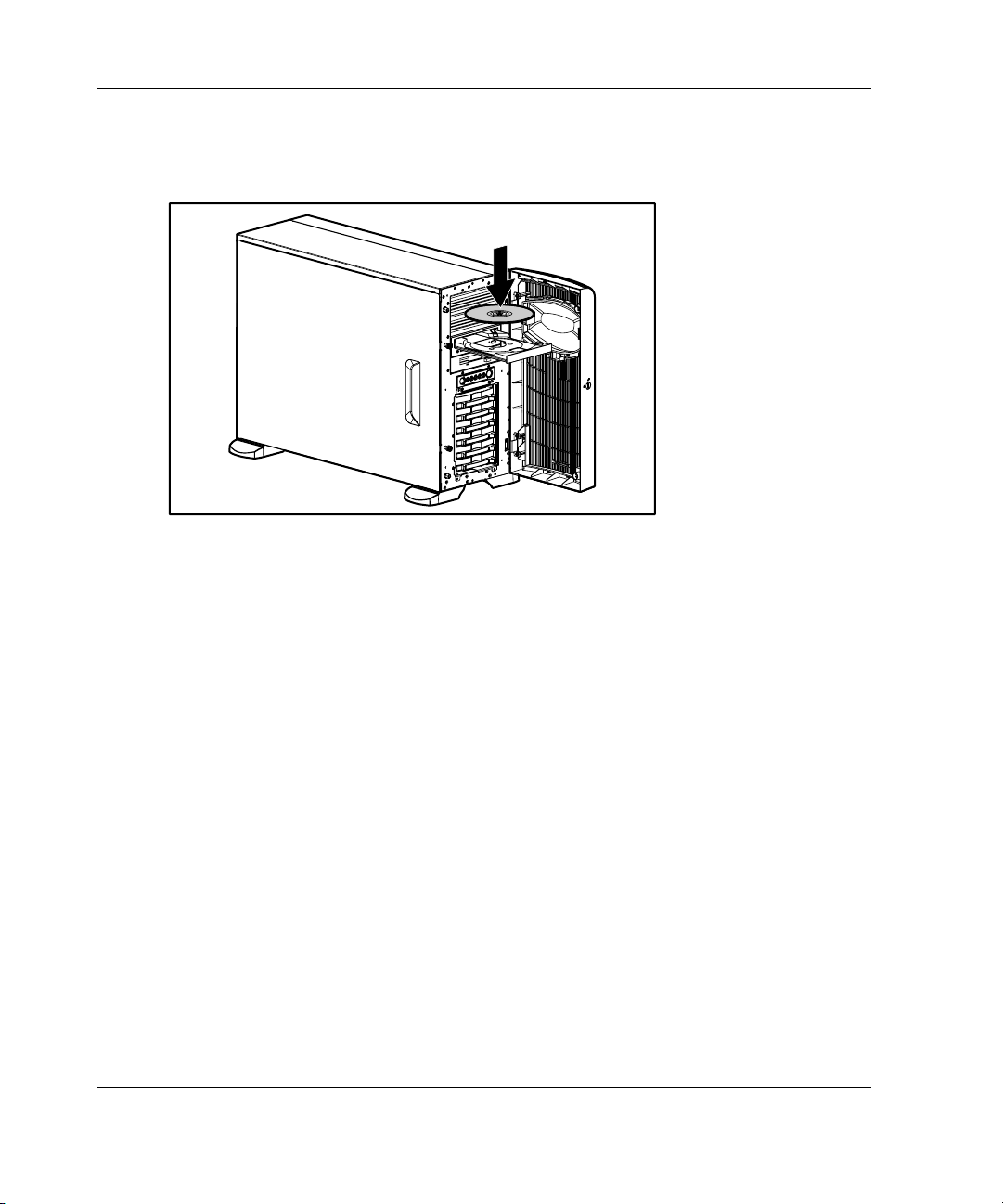
Overview of Server Installation
3. Insert the SmartStart CD into the CD-ROM drive with the labeled side up.
Handle the CD by its edges, not by the flat surfaces of the disc.
Figure 2-22: Inserting a CD into the CD-ROM drive
4. The SmartStart utility sequence begins when the busy indicator on the CD-ROM
turns green. Refer to the SmartStart CD for more information.
Server Registration
For server registration information, refer to the Server Setup and Management pack
shipped with the server, or visit the website www.register.hp.com.
2-34 HP ProLiant ML350 Generation 3 Server Setup and Installation Guide
Page 65

3
Hardware Options Installation
This chapter provides procedures for installing, removing, and replacing hardware
options in the HP ProLiant ML350 Generation 3 server.
CAUTION: Electrostatic discharge (ESD) can damage electronic components of the
server. Before beginning any installation procedure, be sure that you are discharged
of static electricity by briefly touching a grounded metal object.
HP ProLiant ML350 Generation 3 Server Setup and Installation Guide 3-1
Page 66
Hardware Options Installation
Preparing the Server
Before installing or removing any options, prepare the server by performing the
following procedures. Refer to Figure 3-1 and Table 3-1 to review chassis
components.
Chassis Components
1
2
3
4
5
Figure 3-1: Identifying rack and tower chassis
components
Table 3-1: Rack and Tower Chassis Components
Item Description
1 Access panel
2 Removable media bays
3 CD-ROM drive
4 Diskette drive
5 Hard drive bays
3-2 HP ProLiant ML350 Generation 3 Server Setup and Installation Guide
Page 67
Powering Down the Server
To power down the server:
CAUTION: Failure to follow these directions could result in damage to equipment or
loss of information.
1. Back up the server data and record configuration information.
2. Shut down the operating system as directed in your operating system instructions.
3. Power down the server by pressing the power button on the front of the server.
4. Remove the power cord.
WARNING: To reduce the risk of injury from electric shock or damage to the
equipment when installing an upgrade, be sure that the server is powered
down. Remove all AC power cords to completely disconnect power from the
system. The front panel power button may not completely shut down power to
the server.
5. Disconnect any external equipment connections from the server.
Hardware Options Installation
HP ProLiant ML350 Generation 3 Server Setup and Installation Guide 3-3
Page 68

Hardware Options Installation
Removing the Bezel
To remove the bezel:
CAUTION: To prevent damage to equipment or loss of data, be sure that the server
is powered down, all cables are disconnected from the back of the server, and the
power cord is disconnected from the grounded (earthed) AC outlet before removing
the bezel.
1. Follow the steps in “Powering Down the Server” earlier in this chapter.
2. If necessary, unlock the bezel using the included key (1).
3. Open the bezel fully to the right (2).
1
2
Figure 3-2: Unlocking and opening the bezel
3-4 HP ProLiant ML350 Generation 3 Server Setup and Installation Guide
Page 69

Hardware Options Installation
4. To remove the bezel, lift the bezel upward, and pull it away from the chassis.
Figure 3-3: Removing the bezel
5. To replace the bezel, reverse the above procedure.
NOTE: When replacing the bezel, be sure that the bottom hinge points are properly placed in
the chassis before rotating the bezel back into its original position.
Removing the Access Panel in a Tower Server
WARNING: To reduce the risk of personal injury from hot surfaces, allow the
internal system components to cool before touching them.
CAUTION: To prevent damage to equipment or loss of data, be sure that the server
is powered down, all cables are disconnected from the back of the server, and the
power cord is disconnected from the grounded (earthed) AC outlet before removing
the access panel.
CAUTION: Do not operate the server when the large access panel is removed. This
panel is an integral part of the cooling system and removing it while the system is
running may adversely affect data integrity.
HP ProLiant ML350 Generation 3 Server Setup and Installation Guide 3-5
Page 70
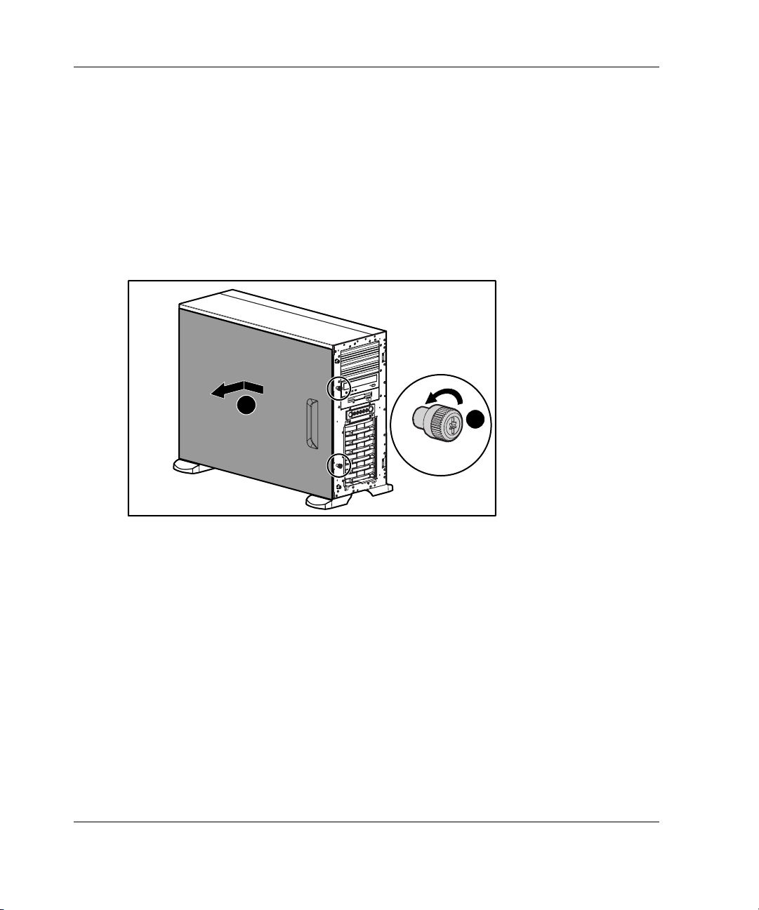
Hardware Options Installation
To remove the access panel:
1. Loosen the two thumbscrews located on the left side of the front chassis (1).
2. Slide the access panel back about 1.5 cm (0.5 inches) (2).
3. Lift and remove the panel.
NOTE: Turn the access panel over to locate the System Configuration hood label. This label
provides information on installing processor board options, configuring drives, installing drives,
LED status indicators, and setting switches.
2
1
Figure 3-4: Loosening the thumbscrews and removing
the access panel
4. To replace the access panel, reverse steps 1 through 3.
3-6 HP ProLiant ML350 Generation 3 Server Setup and Installation Guide
Page 71

Removing the Access Panel in a Rack Server
To extend the server from the rack and remove the access panel:
1. Loosen the two thumbscrews that secure the chassis to the front of the rack (1).
2. Slide the server out of the rack until the sliding rails lock (2).
1
2
Figure 3-5: Sliding the server out of the rack
Hardware Options Installation
HP ProLiant ML350 Generation 3 Server Setup and Installation Guide 3-7
Page 72

Hardware Options Installation
3. Loosen the two thumbscrews located at the top of the front chassis (1).
4. Slide the access panel back about 1.5 cm (0.5 inches) (2).
5. Lift and remove the panel.
Figure 3-6: Removing the access panel
2
1
3-8 HP ProLiant ML350 Generation 3 Server Setup and Installation Guide
Page 73

Removing the Removable Media Device Blanks
NOTE: The blanks must be removed from the chassis to install a storage device in its place.
The tray on the blank is used to mount non-hot plug hard drives into removable media device
bays.
CAUTION: Before removing a removable media device blank, be sure that the
server is powered down, all cables are disconnected from the server, and the power
cord is disconnected from the grounded (earthed) AC outlet.
To remove a removable media device blank from the front chassis:
1. Remove the access panel by following the applicable steps referenced earlier in
this chapter for your tower or rack server.
2. Push up on the drivelock to release the blanks (1).
3. Gently pull the blank away from the front chassis, and then remove the blank (2).
Hardware Options Installation
2
1
Figure 3-7: Removing a removable media device blank
4. To replace a removable media device blank, reverse steps 1 through 3.
HP ProLiant ML350 Generation 3 Server Setup and Installation Guide 3-9
Page 74

Hardware Options Installation
Storage Devices
This section discusses removal and replacement procedures for the storage devices
supported by this server.
Before installing a device, refer to “Tower Server Front Panel Components and Drive
Bay Dimensions” or “Rack Server Front Panel Components and Drive Bay
Dimensions” in Chapter 1, “Server Features,” for the locations and dimensions of the
server drive bays.
CAUTION: To prevent damage to equipment or loss of information, be sure that the
server is powered down, all cables are disconnected from the back of the server, and
the power cord is disconnected from the grounded (earthed) AC outlet before
removing the access panel or front bezel.
IMPORTANT: When you add or remove a component or change a security feature, you must
reconfigure the server to recognize these changes. If the system configuration is incorrect, the
server may not work properly, and you may receive error messages on the screen.
3-10 HP ProLiant ML350 Generation 3 Server Setup and Installation Guide
Page 75
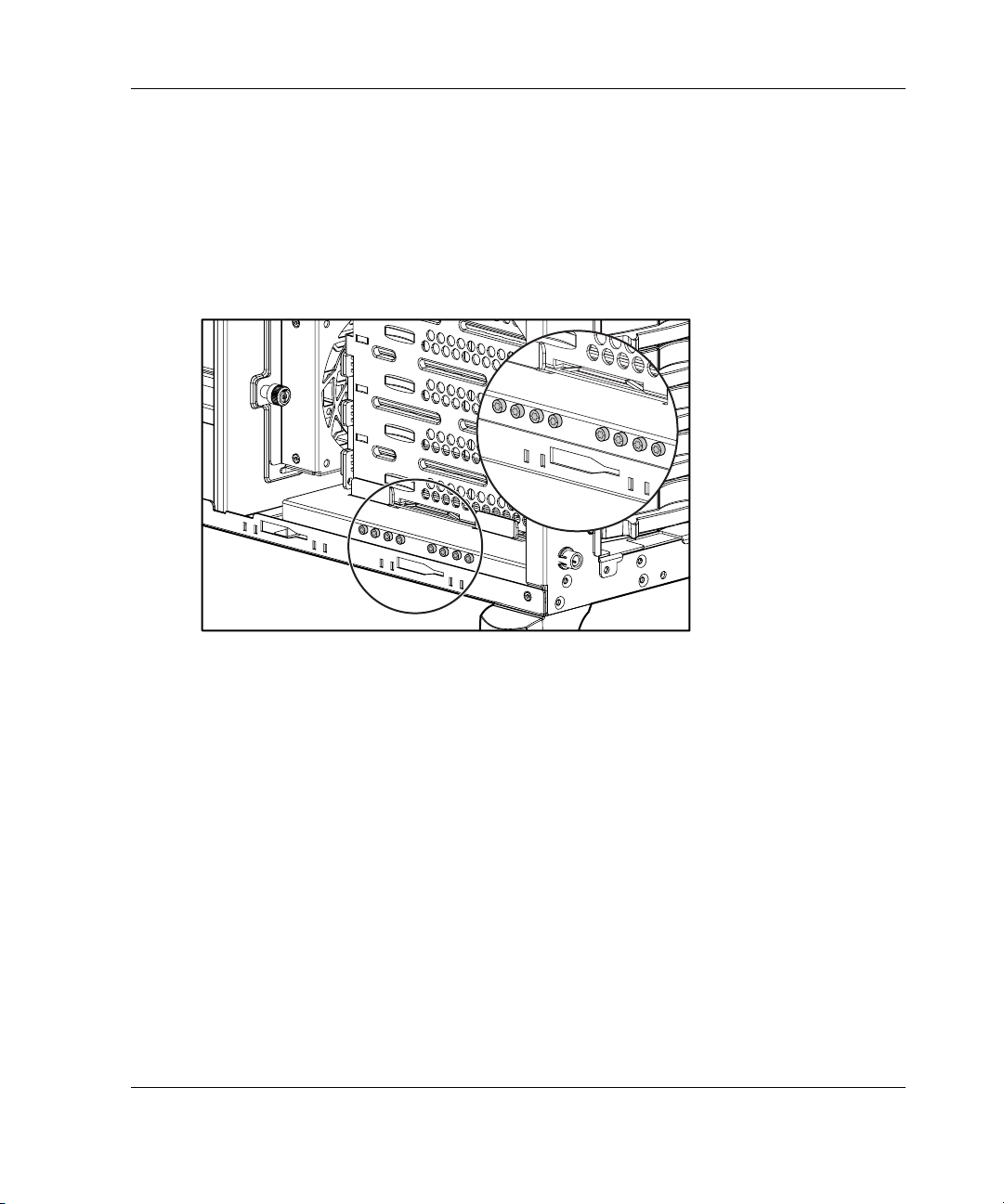
Identifying Guide Screws
When installing drives in the removable media bay, you must install guide screws to
ensure that the drives correctly align in the drive cage. HP has provided extra guide
screws. They are located behind the side access panel of the server. Some options use
5.25 M3 metric screws and some use HD 6-32 screws. The metric screws supplied by
HP are black.
Hardware Options Installation
Figure 3-8: Identifying guide screws
HP ProLiant ML350 Generation 3 Server Setup and Installation Guide 3-11
Page 76

Hardware Options Installation
Installation Guidelines for SCSI Hard Drives
Consider the following guidelines when installing SCSI hard drives:
• • Install drives into the bays in the following order: 0, 1, 2, 3, 4, 5.
SCSI device IDs do not need to be assigned for hot-plug hard drives as the
system will automatically perform that function.
For more information, refer to Figure 3-9 and Chapter 4, “Cabling Guidelines.”
5
4
3
2
1
0
Figure 3-9: Hot-plug SCSI hard drive bay configuration
3-12 HP ProLiant ML350 Generation 3 Server Setup and Installation Guide
Page 77
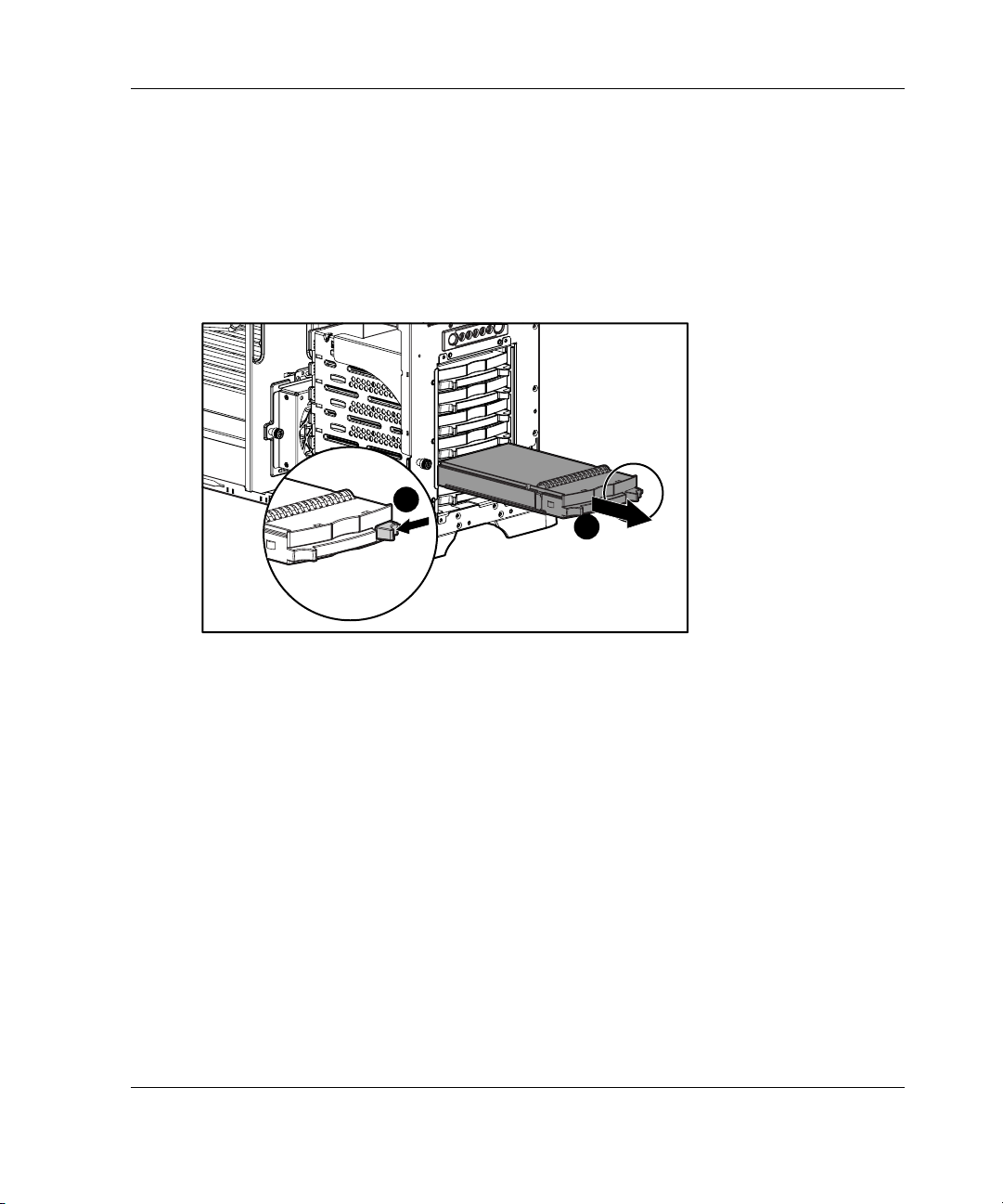
Installing and Removing a Hot-Plug Hard Drive
To install a hot-plug hard drive, first review the installation documentation that came
with the drive.
1. For tower servers, open bezel door.
2. Slide the release latch (1) and remove the hard drive blank (2).
1
2
Hardware Options Installation
Figure 3-10: Removing the hard drive blank
HP ProLiant ML350 Generation 3 Server Setup and Installation Guide 3-13
Page 78
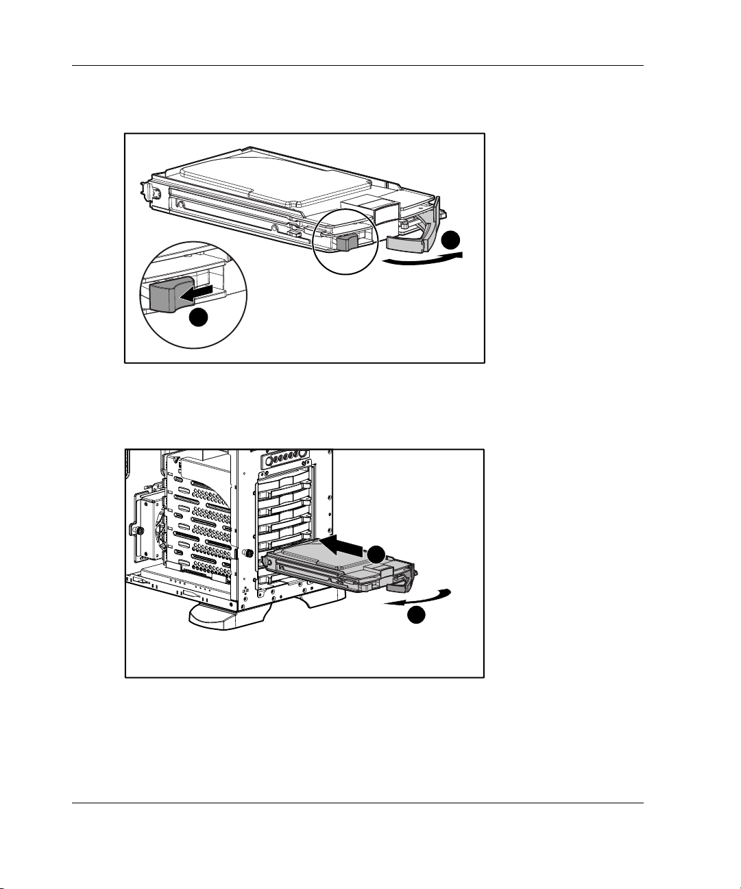
Hardware Options Installation
3. Slide the hard drive release latch (1) and open the ejector lever (2).
1
Figure 3-11: Opening the ejector lever
4. Insert the hot-plug hard drive into the lowest available hot-plug drive bay (1),
then close the ejector lever (2).
2
1
2
Figure 3-12: Inserting the hot-plug hard drive and
closing the ejector lever
5. To remove a hot-plug hard drive, reverse steps 1 through 4.
3-14 HP ProLiant ML350 Generation 3 Server Setup and Installation Guide
Page 79

IMPORTANT: A hard drive blank must be installed into any empty drive bay for the system to
properly operate.
Installing a Device into a Removable Media Bay
The server includes four removable media bays. The lower two bays are occupied
with a 3.5-inch diskette drive and an IDE CD-ROM drive. The upper two removable
media device bays are vacant. You can install two half-height devices or one
full-height device into these bays.
Installing a Half-Height Removable Media Device
To install a 5.25-inch device:
CAUTION: To prevent damage to equipment or loss of information, be sure that the
server is powered down, all cables are disconnected from the server, and the power
cord is disconnected from the grounded (earthed) AC outlet before removing the
access panel.
1. Remove the access panel by following the steps in the section applicable to your
tower or rack server at the beginning of this chapter.
NOTE: For tower servers, the bezel door can be removed to simplify access.
Hardware Options Installation
2. To configure the device, set the SCSI ID. You must manually set the SCSI ID on
each device to a unique value. Refer to the documentation provided with the
device for instructions on setting the SCSI ID.
3. Remove all terminating jumpers from third-party SCSI devices.
4. Install guide screws on the sides of the drive.
HP ProLiant ML350 Generation 3 Server Setup and Installation Guide 3-15
Page 80

Hardware Options Installation
5. Slide the drive into the drive bay until it clicks into place.
Figure 3-13: Installing a device mounted inside a
removable media bay
3-16 HP ProLiant ML350 Generation 3 Server Setup and Installation Guide
Page 81
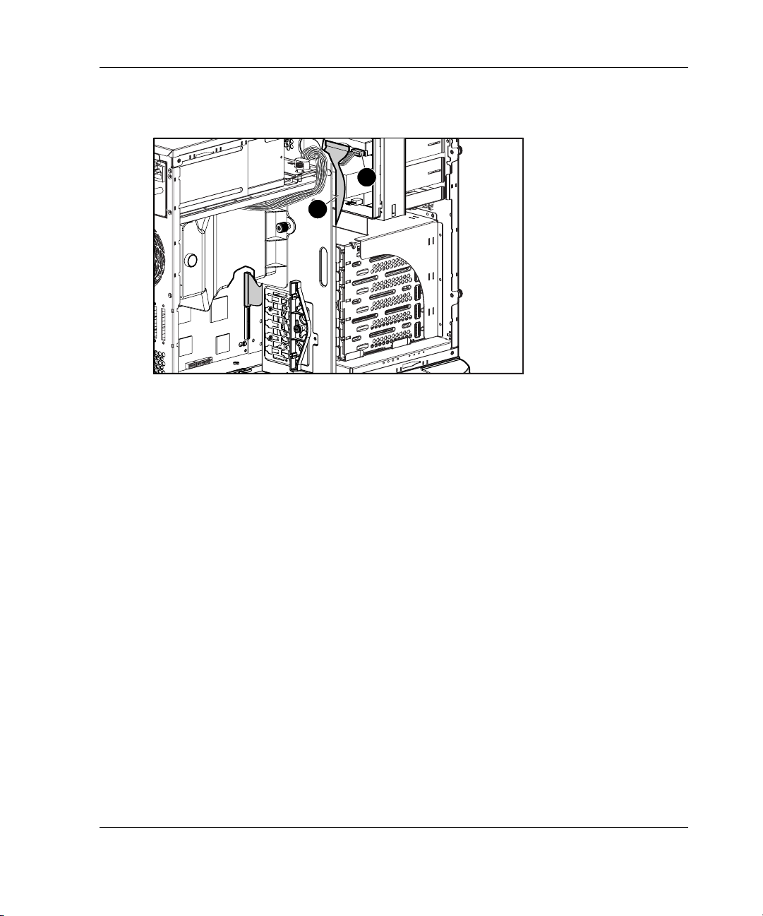
Hardware Options Installation
6. Connect the data cable (1) and power cable (2) to the back of the drive.
2
1
Figure 3-14: Connecting the data and power cables
7. Connect the data cable into a SCSI controller channel (secondary SCSI channel
shown in Figure 3-14).
HP ProLiant ML350 Generation 3 Server Setup and Installation Guide 3-17
Page 82

Hardware Options Installation
Installing a Tape Drive
To install a tape drive:
CAUTION: To prevent damage to equipment or loss of information, be sure that the
server is powered down, all cables are disconnected from the server, and the power
cord is disconnected from the grounded (earthed) AC outlet before removing the
access panel.
1. Remove the access panel (and bezel door if applicable) by following the steps in
the section applicable to your tower or rack server at the beginning of this
chapter.
2. Install guide screws on the sides of the drive.
3. To configure the device, set the SCSI device ID. You must manually set the SCSI
device ID on each device to a unique value in the range of 0 through 5 for each
SCSI bus. Refer to the documentation provided with the drive for instructions on
setting the SCSI device ID.
4. Slide the drive into the drive bay until it clicks into place.
Figure 3-15: Installing a tape drive (DLT)
IMPORTANT: HP recommends installing the tape drive on a separate SCSI cable to avoid a
decrease in performance of other SCSI devices.
3-18 HP ProLiant ML350 Generation 3 Server Setup and Installation Guide
Page 83

Hardware Options Installation
5. Connect the data cable (1) and power cable (2) to the back of the drive.
2
1
Figure 3-16: Connecting the data and power cables to
the tape drive
6. Connect the data cable into a SCSI controller channel (secondary SCSI channel
shown in Figure 3-16).
HP ProLiant ML350 Generation 3 Server Setup and Installation Guide 3-19
Page 84

Hardware Options Installation
Removing a Device from Removable Media Bay
To remove a tape drive or other device:
CAUTION: To prevent damage to equipment or loss of information, be sure that the
server is powered down, all cables are disconnected from the server, and the power
cord is disconnected from the grounded (earthed) AC outlet before removing the
access panel.
1. Remove the access panel (and bezel door if applicable) by following the steps in
the section applicable to your tower or rack server at the beginning of this
chapter.
2. Disconnect the power cable and data cable from the back of the tape drive.
Figure 3-17: Disconnecting the power and data cables
3-20 HP ProLiant ML350 Generation 3 Server Setup and Installation Guide
Page 85

Hardware Options Installation
3. While pushing the drivelock up (1), pull the tape drive out of the drive bay (2).
2
1
Figure 3-18: Releasing the tape drive
4. Remove the guide screws on the sides of the drive.
5. Install drive blanks into any empty bays.
6. Reinstall the access panel.
HP ProLiant ML350 Generation 3 Server Setup and Installation Guide 3-21
Page 86

Hardware Options Installation
Installing an Expansion Board
Figure 3-19 and Table 3-2 identify the location of expansion slots.
1
2
3
4
5
Figure 3-19: Locating expansion slots
Table 3-2: Expansion Slots
Item Slot Type Slot Number
1 3.3 V, 64-bit PCI-X 100 MHz (bus 2) 1
2 3.3 V, 64-bit PCI-X 100 MHz (bus 2) 2
3 3.3 V, 64-bit PCI-X 100 MHz (bus 5) 3
4 3.3 V, 64-bit PCI-X 100 MHz (bus 5) 4
5 5.0 V, 32-bit PCI 33 MHz 5
NOTE: Slots 1, 2, 3 and 4 are optimized for PCI-X 100 add-in cards.
This server supports two independent 64-bit, 133 MHz PCI-X segments (buses) for
increased performance and platform flexibility. For optimum load balancing when
installing PCI-X expansion boards, populate expansion slots across different buses
before populating two slots on the same bus. Refer to Figure 3-19 and Table 3-2 to
identify the slot positions by bus number.
3-22 HP ProLiant ML350 Generation 3 Server Setup and Installation Guide
Page 87

Hardware Options Installation
IMPORTANT: Always pair expansion boards of the same speed on the same bus for optimum
performance. If expansion boards of different speeds are installed on the same bus (for
example, 66-MHz PCI and 100-MHz PCI-X boards), the server operates both boards at the
lower frequency.
To install an expansion board:
CAUTION: To prevent damage to equipment or loss of information, be sure that the
server is powered down, all cables are disconnected from the back of the server, and
the power cord is disconnected from the grounded (earthed) AC outlet before
removing the access panel.
1. Remove the access panel by following the steps in the section applicable to your
tower or rack server at the beginning of this chapter.
2. Loosen the thumbscrew of the expansion board retainer (1), then pull the retainer
out and away from the chassis (2).
1
2
Figure 3-20: Removing the expansion board retainer
HP ProLiant ML350 Generation 3 Server Setup and Installation Guide 3-23
Page 88

Hardware Options Installation
3. Press on the top of the expansion slot latch (1), then open the latch toward the
rear of the chassis (2).
4. Remove the expansion slot cover (3).
IMPORTANT: It may be necessary to remove the slot cover next to the slot in which you are
installing a board.
2
1
3
Figure 3-21: Removing the expansion slot cover
IMPORTANT: Be sure to insert expansion boards into the appropriate type of expansion slot.
The 32-bit expansion boards can be inserted into either the 32-bit slot or 64-bit slots, however
the 64-bit expansion boards must be inserted into 64-bit expansion slots.
3-24 HP ProLiant ML350 Generation 3 Server Setup and Installation Guide
Page 89
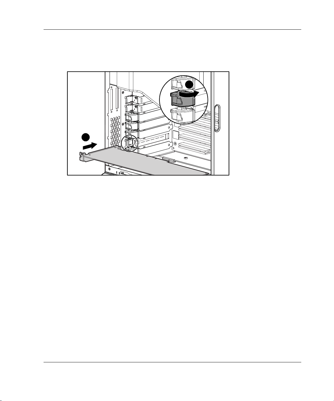
5. Insert the expansion board (1).
6. Close the expansion slot latch to secure the board (2).
2
1
Figure 3-22: Installing an expansion board
7. Connect any cables to the expansion board.
Hardware Options Installation
HP ProLiant ML350 Generation 3 Server Setup and Installation Guide 3-25
Page 90
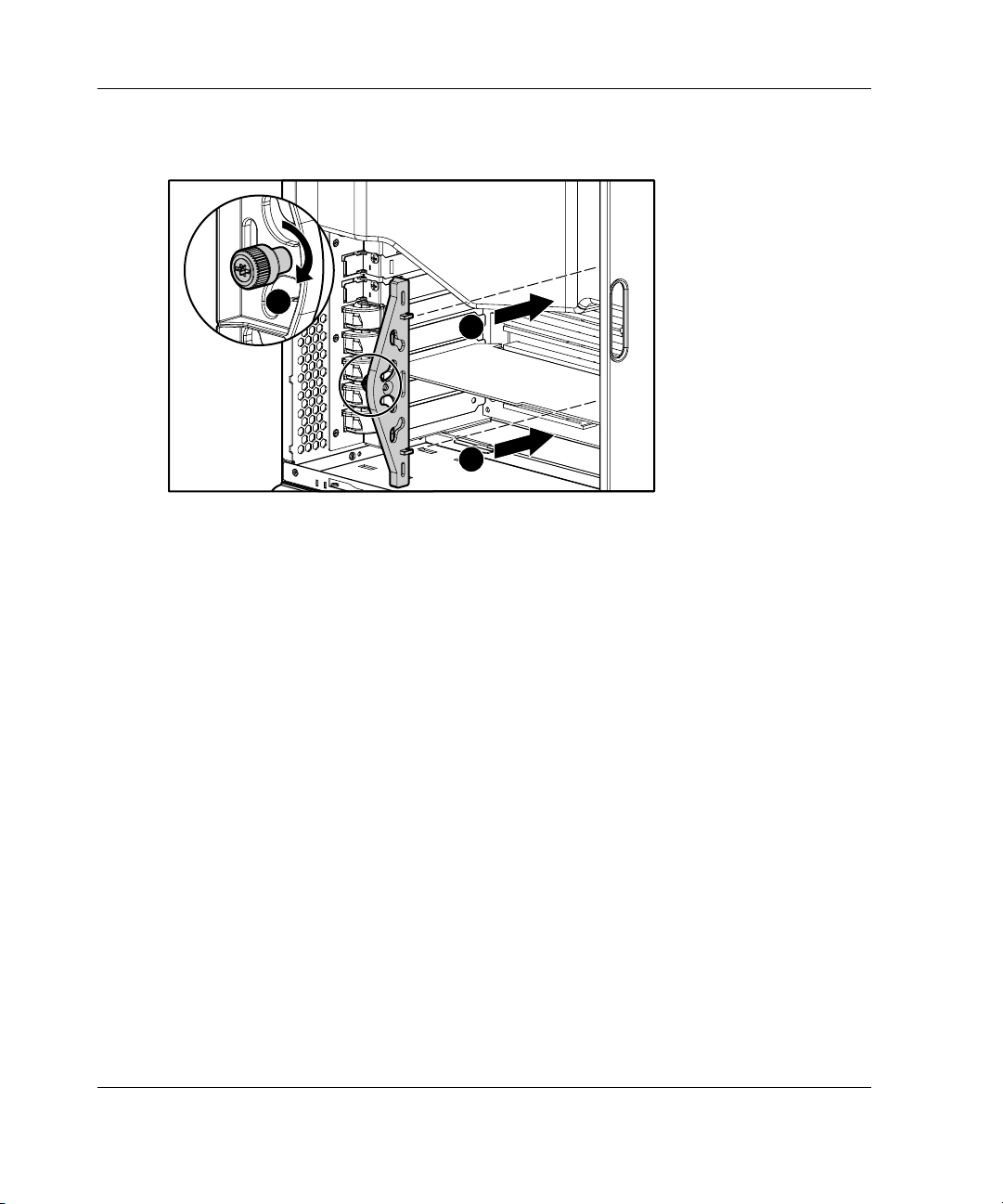
Hardware Options Installation
8. Reinstall the expansion board retainer (1), then tighten the thumbscrew (2).
2
Figure 3-23: Reinstalling the expansion board retainer
9. Reinstall the access panel.
10. To remove an expansion board, reverse steps 1 through 9.
1
1
3-26 HP ProLiant ML350 Generation 3 Server Setup and Installation Guide
Page 91
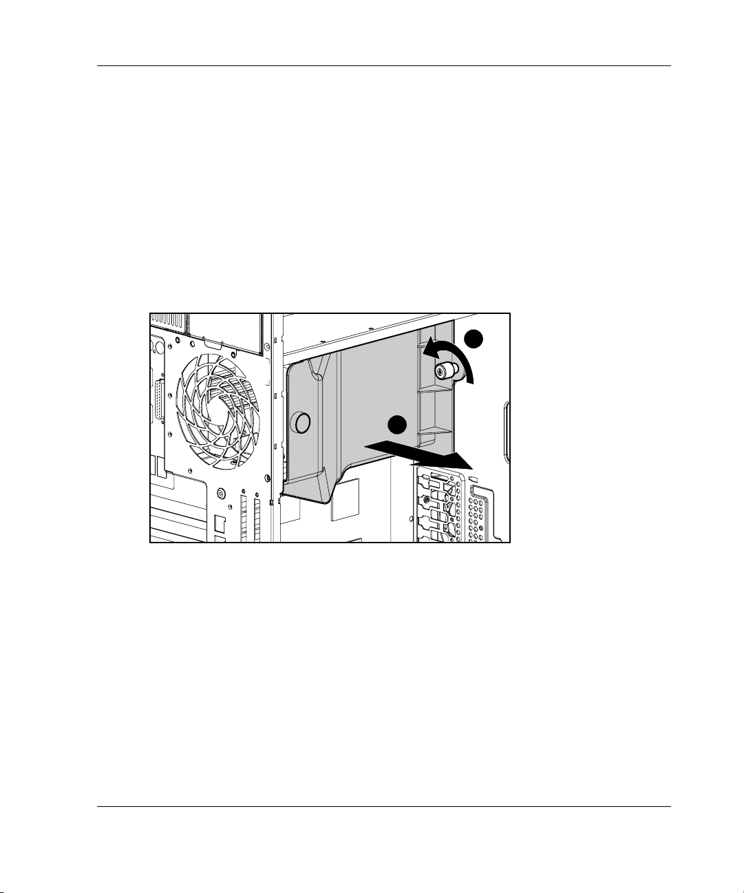
Removing the Fan Baffle
To remove the fan baffle:
1. Remove the access panel by following the steps in the section applicable to your
tower or rack server at the beginning of this chapter.
2. Remove expansion board retainer by following steps referenced earlier in this
chapter in section “Installing an Expansion Board.”
3. Loosen the thumbscrew that secures the baffle to the fan (1).
4. Slide the baffle out and away from the chassis (2).
Hardware Options Installation
1
2
Figure 3-24: Removing the fan baffle
HP ProLiant ML350 Generation 3 Server Setup and Installation Guide 3-27
Page 92

Hardware Options Installation
Memory Modules
Technical Information and Important Guidelines
CAUTION: To prevent damage to equipment or loss of information, be sure that the
server is powered down, all cables are disconnected from the back of the server, and
the power cord is disconnected from the grounded (earthed) AC outlet before
removing the access panel.
CAUTION: To prevent damage to the system when handling components, see
Appendix B, “Electrostatic Discharge.”
CAUTION: When handling a memory module, be careful not to touch any of the
contacts. Doing so may damage the module.
When installing DIMMs, you must follow these guidelines:
•
DIMMs must be industry-standard 184-pin PC2100 DDR DIMMs. The DDR
DIMMs must support CAS Latency 2, or greater. They must also contain the
mandatory Joint Electronic Device Engineering Council (JEDEC) Serial
Presence Detect (SPD) information.
•
Do not mix ECC and non-ECC DDR DIMMs. If different types of DIMMs are
mixed, the system does not properly function.
•
A DIMM can be installed only one way. Be sure to match the two key slots on
the DIMM with the tab on the DIMM socket. Push the DIMM down into the
DIMM socket, ensuring that it is fully inserted and properly seated.
•
DIMMs can be installed in pairs or singularly. Installing DIMMs in identical
pairs allows for the activation of the Memory Interleaving capability (refer to
“Interleaving and Non-Interleaving Memory Configuration” later in this chapter).
3-28 HP ProLiant ML350 Generation 3 Server Setup and Installation Guide
Page 93

Hardware Options Installation
Interleaving and Non-Interleaving Memory Configuration
This server supports both interleaving and non-interleaving memory configurations.
Interleaving memory increases bandwidth by allowing simultaneous access to more
than one block of data (for example, overlapping Read-Writes). This is accomplished
by dividing the system memory between pairs of DIMMs and Writing-Reading
blocks of data to/from both simultaneously. In order to take advantage of interleaving
memory, identical DIMMS must be installed in pairs. DIMMs can also be installed
singularly if memory interleaving is not desired.
Activating Interleaving Memory
Interleaving memory functionality is automatically activated whenever two identical
DIMMs are detected in sockets 1 and 2. If sockets 3 and 4 are populated, it must be
with identical DIMMs as well. If identical DIMMs are installed in sockets 1, 2 and 3,
this is considered non-interleaving. You must have an even number of DIMMs
installed to support interleaving.
The server identifies memory mode in two ways. At post, the ROM will display a
interleaving or non-interleaving message. In addition, The RBSU main menu will
identify the memory mode following the
the information block to the right of the menu options list. Refer to Chapter 5,
“Server Configuration and Utilities” for more information.
XXXMB Memory Installed message in
Interleaving Memory Guidelines
For interleaving memory functionality, follow the guidelines noted below:
• • Memory must be installed in identical pairs. Pairs are considered to be DIMMs
installed in sockets 1 and 2 or 3 and 4.
Populate DIMM sockets 1 and 2 first before installing in sockets 3 and 4
(if needed). Refer to Figure 3-25 and Table 3-3.
HP ProLiant ML350 Generation 3 Server Setup and Installation Guide 3-29
Page 94
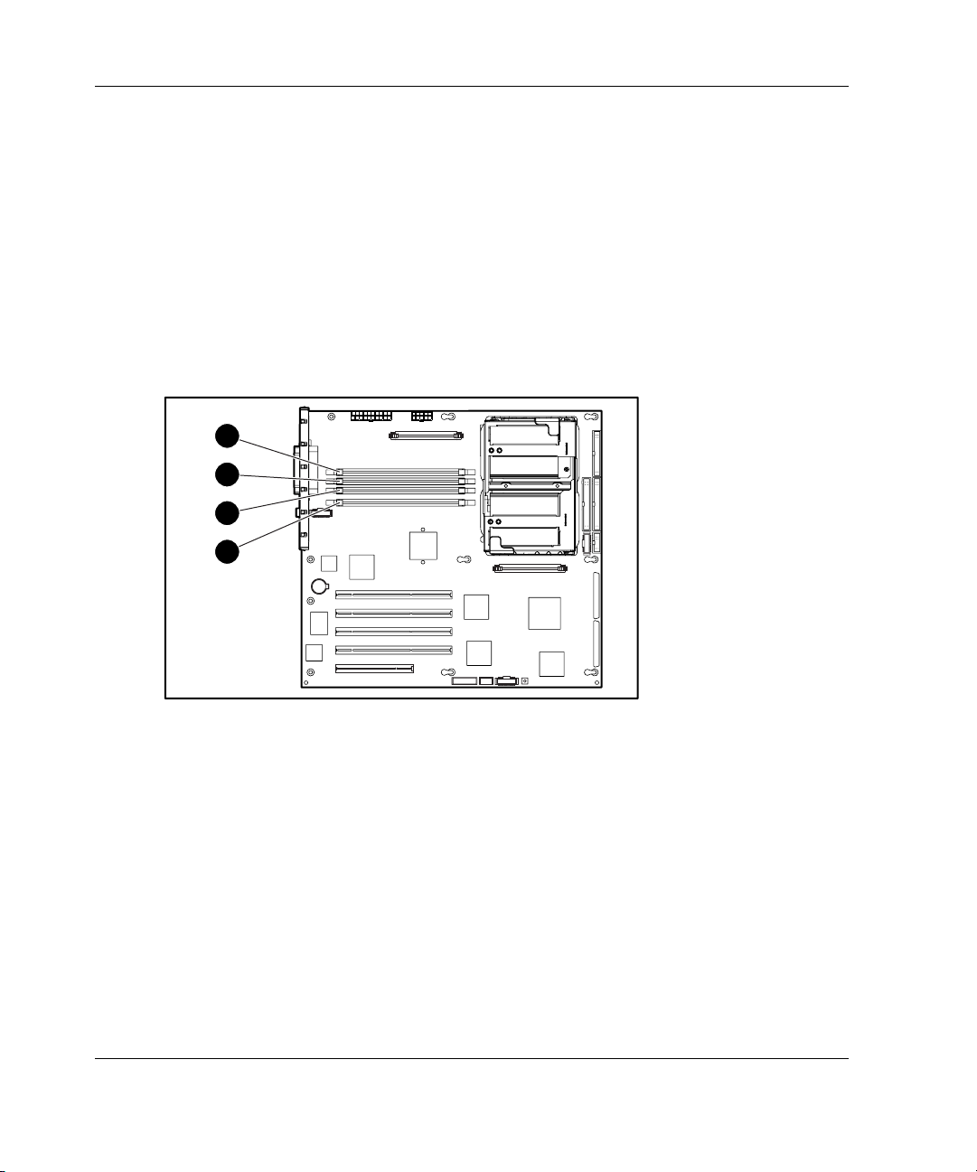
Hardware Options Installation
Installing a Memory Module
This server supports up to 8 GB of memory. Memory can be installed singularly in
DIMM socket position 1 (non-interleaving memory) or in combinations of 128-MB,
256-MB, 512-MB, 1-GB, and 2-GB modules (to support interleaving memory
functionality). The server has four DIMM sockets located on the system board (refer
to Figure 3-25).
IMPORTANT: DIMMs do not need to be installed in pairs (unless memory interleaving is
desired). If interleaving memory capability is desired, follow the appropriate DIMM installation
guidelines noted earlier in this chapter.
4
3
2
1
Figure 3-25: Locating DIMM sockets
NOTE: Refer to Appendix E, “LED Indicators, Switches, and Jumpers” for a description of the
DIMM LEDs.
3-30 HP ProLiant ML350 Generation 3 Server Setup and Installation Guide
Page 95

Hardware Options Installation
Table 3-3: DIMM Sockets
Item Component
1 DIMM socket 1, Pair 1
2 DIMM socket 2, Pair 1
3 DIMM socket 3, Pair 2
4 DIMM socket 4, Pair 2
HP ProLiant ML350 Generation 3 Server Setup and Installation Guide 3-31
Page 96

Hardware Options Installation
To install a DIMM:
1. Remove the access panel by following the steps in the section applicable to your
tower or rack server at the beginning of this chapter.
2. Remove the fan baffle by performing the steps in “Removing the Fan Baffle”
earlier in this chapter.
3. Press outward on both latches of the DIMM socket at the same time.
4. Insert the DIMM into the socket (1).
5. Return latches to the upright position (2).
2
2
1
Figure 3-26: Installing a DIMM
6. Reinstall the fan baffle.
7. Reinstall the access panel.
3-32 HP ProLiant ML350 Generation 3 Server Setup and Installation Guide
Page 97

Removing a Memory Module
To remove a DIMM:
CAUTION: Before removing the access panel, be sure that the server is powered
down, all cables are disconnected from the back of the server, and the power cord is
disconnected from the grounded (earthed) AC outlet.
1. Remove the access panel by following the steps in the section applicable to your
tower or rack server at the beginning of this chapter.
2. Remove the fan baffle by performing the steps in “Removing the Fan Baffle”
earlier in this chapter.
3. Press outward on both latches of the DIMM socket at the same time. This step
releases the DIMM and pushes it partially out of the socket (1).
4. Lift the DIMM from the socket (2).
Hardware Options Installation
1
1
2
Figure 3-27: Removing a DIMM
5. Reinstall the fan baffle.
6. Reinstall the access panel.
HP ProLiant ML350 Generation 3 Server Setup and Installation Guide 3-33
Page 98

Hardware Options Installation
Processors and Processor Power Modules
WARNING: To reduce the risk of personal injury from hot surfaces, allow the
internal system components to cool before touching them.
CAUTION: To prevent damage to equipment or loss of information, be sure that the
server is powered down, all cables are disconnected from the back of the server, and
the power cord is disconnected from the grounded (earthed) AC outlet before
removing the access panel.
CAUTION: Static electricity can damage electronic components of the server.
Before beginning these procedures, be sure that you are discharged of static
electricity by briefly touching a grounded metal object.
For written instructions and illustrated procedures on installing or removing a
processor or Processor Power Module (PPM), refer to the installation documentation
that came with the option kit.
Installing a Processor with Heatsink in the Processor Cage
This server supports the installation of a second Intel Xeon processor for enhanced
performance. Processor option kits available for the server consist of an Intel Xeon
processor with heatsink and a Power Processor Module (PPM).
IMPORTANT: Only install the specific PPM provided in the option kit with your processor.
Observe the warnings and cautions provided in the option kit documentation and in
this guide. To install the processor and heatsink assembly:
1. Be sure that all critical data has been backed up.
2. Be sure that the server has the most current ROM version. To update your ROM,
refer to
www.compaq.com/support/files.
3. Power down the server and remove the access panel as described in the section
applicable to your tower or rack server earlier in this chapter.
4. Remove the internal fan baffle to gain access to the processor sockets. Refer to
“Removing the Fan Baffle” earlier in this chapter.
3-34 HP ProLiant ML350 Generation 3 Server Setup and Installation Guide
Page 99

Hardware Options Installation
5. Locate the processor socket and corresponding PPM slot on the system board.
1 2
3
4
Figure 3-28: Locating the processor sockets and
Processor Power Module (PPM) slots
Table 3-4: Processor Sockets and Processor Power Module Slots
Item Description
1 PPM slot 1
2 Processor socket 1
3 Processor socket 2
4 PPM slot 2
HP ProLiant ML350 Generation 3 Server Setup and Installation Guide 3-35
Page 100
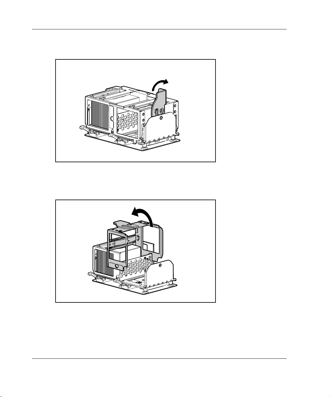
Hardware Options Installation
6. Pull up on the processor cage retaining bracket latch.
Figure 3-29: Lifting the processor cage retaining
bracket latch
7. Lift processor cage upward.
Figure 3-30: Lifting the processor cage
3-36 HP ProLiant ML350 Generation 3 Server Setup and Installation Guide
 Loading...