

Page 1

ProLiant ML350 Generation 2 Server
Setup and Installation Guide
Second Edition (October 2001)
Part Number 236843-002
Compaq Computer Corporation
Page 2

Notice
© 2001 Compaq Computer Corporation
Compaq, the Compaq logo, Compaq Insight Manager, ProLiant, ROMPaq, CarePaq, and SmartStart are
trademarks of Compaq Information Technologies Group, L.P.
Microsoft, MS-DOS, Windows, and Windows NT are trademarks of Microsoft Corporation.
Intel and Pentium are trademarks of Intel Corporation.
All other product names mentioned herein may be trademarks of their respective companies.
Compaq shall not be liable for technical or editorial errors or omissions contained herein. The
information in this document is provided “as is” without warranty of any kind and is subject to change
without notice. The warranties for Compaq products are set forth in the express limited warranty
statements accompanying such products. Nothing herein should be construed as constituting an
additional warranty.
Compaq ProLiant ML350 Generation 2 Server
Setup and Installation Guide
Second Edition (October 2001)
Part Number 236843-002
Page 3

Contents
About This Guide
Text Conventions..................................................................................................... viii
Symbols in Text..........................................................................................................ix
Symbols on Equipment...............................................................................................ix
Rack Stability .............................................................................................................xi
Important Safety Information .....................................................................................xi
Getting Help ...............................................................................................................xi
Compaq Technical Support ................................................................................xii
Compaq Website ................................................................................................xii
Compaq Authorized Reseller..............................................................................xii
Chapter 1
Server Features
Standard Hardware Features.................................................................................... 1-4
Tower Server Front Panel Components and Drive Bay Dimensions................ 1-4
Rack Server Front Panel Components and Drive Bay Dimensions.................. 1-5
Tower Server Rear Panel Components............................................................. 1-6
Rack Server Rear Panel Components............................................................... 1-7
System Board Components .............................................................................. 1-8
LEDs and Buttons........................................................................................... 1-10
Processors and System Memory..................................................................... 1-11
Expansion Slots .............................................................................................. 1-11
Storage Controller .......................................................................................... 1-11
Network Interface Controller.......................................................................... 1-12
Ports and Connectors...................................................................................... 1-12
Power Supply.................................................................................................. 1-12
Server Feature Board Components................................................................. 1-13
Warranty......................................................................................................... 1-14
Server Configuration and Management................................................................. 1-15
Security.................................................................................................................. 1-16
Page 4

iv Compaq ProLiant ML350 Generation 2 Server Setup and Installation Guide
Chapter 2
Overview of Server Installation
Selecting a Site......................................................................................................... 2-2
Installing the Rack Server........................................................................................ 2-3
Tower-to-Rack Option...................................................................................... 2-3
Rack Environment ............................................................................................ 2-4
Locating Materials ................................................................................................... 2-5
Installation Sequence ............................................................................................... 2-6
Factory-Installed Operating Systems................................................................ 2-7
Operating System Purchased Separately........................................................... 2-9
Configuring the Server........................................................................................... 2-11
Server Registration................................................................................................. 2-11
Chapter 3
Hardware Options Installation
Preparing the Server................................................................................................. 3-2
Chassis Components......................................................................................... 3-2
Powering Down the Server ............................................................................... 3-3
Removing the Bezel.......................................................................................... 3-4
Removing the Access Panel in a Tower Server ................................................ 3-5
Removing the Access Panel in a Rack Server ..................................................3-7
Removing the Removable Media Device Blanks ............................................. 3-9
Storage Devices ..................................................................................................... 3-10
Identifying Guide Screws ...............................................................................3-10
Installation Guidelines for SCSI Hard Drives................................................. 3-11
Installing and Removing a Hot-Plug Hard Drive............................................ 3-12
Installing a Device into a Removable Media Bay........................................... 3-15
Removing a Device from Removable Media Bay .......................................... 3-18
Installing an Expansion Board ............................................................................... 3-20
Removing the Fan Baffle....................................................................................... 3-25
Memory Modules................................................................................................... 3-26
Technical Information and Important Guidelines........................................... 3-26
Installing a Memory Module ..........................................................................3-27
Removing a Memory Module......................................................................... 3-29
Processors and Processor Power Modules............................................................. 3-30
Installing a Processor with Heatsink............................................................... 3-30
Installing a Processor Power Module..............................................................3-34
Removing a Processor ....................................................................................3-35
Removing a Processor Power Module............................................................ 3-36
Replacing Batteries ................................................................................................ 3-36
Replacing the System Board Battery .............................................................. 3-37
Replacing the Server Feature Board Battery................................................... 3-39
Installing the Hot-Plug Redundant Power Supply ................................................. 3-40
Page 5

Chapter 4
Cabling Guidelines
Storage Device Installation Guidelines.................................................................... 4-2
Identifying SCSI Components.......................................................................... 4-3
Cabling SCSI Devices in the Removable Media Area ..................................... 4-6
Cabling a Smart Array or Other RAID Controller............................................ 4-7
Installing an Internal-to-External SCSI Connector........................................... 4-9
Connecting IDE Devices to the Integrated IDE Controller ............................ 4-10
Connecting the System Fan ............................................................................ 4-11
Chapter 5
Server Configuration and Utilities
ROM Based Setup Utility........................................................................................ 5-2
Navigating RBSU............................................................................................. 5-2
Using RBSU ..................................................................................................... 5-3
ROMPaq .................................................................................................................. 5-7
SmartStart for Servers Software .............................................................................. 5-8
SmartStart Diskette Builder ..................................................................................... 5-8
Compaq Insight Manager ........................................................................................ 5-9
Compaq Survey Utility............................................................................................ 5-9
Compaq Diagnostics Utility................................................................................... 5-10
Automatic Server Recovery-2 ............................................................................... 5-10
Power-On Self-Test ............................................................................................... 5-10
Contents v
Appendix A
Regulatory Compliance Notices
Regulatory Compliance Identification Numbers .....................................................A-1
Federal Communications Commission Notice ........................................................A-2
Class A Equipment ..................................................................................................A-2
Class B Equipment ..................................................................................................A-3
Declaration of Conformity for Products Marked with the FCC Logo—
United States Only............................................................................................A-4
Modifications....................................................................................................A-4
Cables ...............................................................................................................A-4
Mouse Compliance Statement ..........................................................................A-5
Canadian Notice (Avis Canadien) ...........................................................................A-5
Class A Equipment...........................................................................................A-5
Class B Equipment ...........................................................................................A-5
European Union Notice ...........................................................................................A-5
Japanese Notice .......................................................................................................A-6
Taiwanese Notice.....................................................................................................A-6
Battery Replacement Notice ....................................................................................A-7
Laser Compliance ....................................................................................................A-8
Power Cords ............................................................................................................A-9
Page 6

vi Compaq ProLiant ML350 Generation 2 Server Setup and Installation Guide
Appendix B
Electrostatic Discharge
Preventing Electrostatic Discharge ......................................................................... B-1
Grounding Methods ................................................................................................ B-2
Appendix C
Server Error Messages
Appendix D
Troubleshooting
When the Server Does Not Start ............................................................................. D-3
Diagnosis Steps................................................................................................ D-5
Problems After Initial Startup ................................................................................. D-8
Other Information Resources................................................................................ D-12
Appendix E
LED Indicators, Switches, and Jumpers
LEDs ........................................................................................................................E-2
System Status LEDs..........................................................................................E-2
System Board LEDs..........................................................................................E-5
Network Controller LEDs.................................................................................E-7
System Configuration Switch Settings.....................................................................E-8
Resetting System Configuration Settings .........................................................E-9
Redundant ROM Settings ...............................................................................E-10
SCSI Device Jumper Settings ................................................................................E-10
Appendix F
Specifications
Server Specifications ...............................................................................................F-2
Rack Server....................................................................................................... F-3
Minimum Hardware Configuration..........................................................................F-4
Supported Operating Systems.................................................................................. F-5
Drivers .....................................................................................................................F-5
Index
Page 7

About This Guide
This guide is designed to be used as a set of step-by-step instructions for the
installation of Compaq ProLiant ML350 Generation 2 servers and as a
reference for operation, troubleshooting, and future upgrades of the server.
Page 8

viii Compaq ProLiant ML350 Generation 2 Server Setup and Installation Guide
Text Conventions
This document uses the following conventions to distinguish elements of text:
Keys Keys appear in boldface. A plus sign (+) between
two keys indicates that they should be pressed
simultaneously.
USER INPUT User input appears in a different typeface and in
uppercase.
FILENAMES File names appear in uppercase italics.
Menu Options,
Command Names,
Dialog Box Names
COMMANDS,
DIRECTORY NAMES,
and DRIVE NAMES
Type When you are instructed to type information, type
Enter When you are instructed to enter information, type
Websites Unless otherwise noted within the body of this
These elements appear in initial capital letters and
may appear in bold for emphasis.
These elements appear in uppercase and may appear
in bold for emphasis.
the information without pressing the Enter key.
the information, and then press the Enter key.
guide, all URLs begin with the http:// default prefix.
Page 9
Symbols in Text
These symbols may be found in the text of this guide. They have the following
meanings.
WARNING: Text set off in this manner indicates that failure to follow directions
in the warning could result in bodily harm or loss of life.
CAUTION: Text set off in this manner indicates that failure to follow directions
could result in damage to equipment or loss of information.
IMPORTANT: Text set off in this manner presents clarifying information or specific
instructions.
NOTE: Text set off in this manner presents commentary, sidelights, or interesting points
of information.
Symbols on Equipment
About This Guide ix
The following symbols may be placed on equipment to indicate the presence
of potentially hazardous conditions:
This symbol, in conjunction with any of the following symbols, indicates
the presence of a potential hazard. The potential for injury exists if
warnings are not observed. Consult your documentation for specific
details.
This symbol indicates the presence of hazardous energy circuits or electric
shock hazards. Refer all servicing to qualified personnel.
WARNING: To reduce the risk of injury from electric shock hazards, do not
open this enclosure. Refer all maintenance, upgrades, and servicing to
qualified personnel.
This symbol indicates the presence of electric shock hazards. The area
contains no user- or field-serviceable parts. Do not open for any reason.
WARNING: To reduce the risk of injury from electric shock hazards, do
not open this enclosure.
Page 10
x Compaq ProLiant ML350 Generation 2 Server Setup and Installation Guide
This symbol on an RJ-45 receptacle indicates a network interface
connection.
WARNING: To reduce the risk of electric shock, fire, or damage to the
equipment, do not plug telephone or telecommunications connectors into
this receptacle.
This symbol indicates the presence of a hot surface or hot component. If
this surface is contacted, the potential for injury exists.
WARNING: To reduce the risk of injury from a hot component, allow the
surface to cool before touching it.
These symbols, on power supplies or systems, indicate the
equipment is supplied by multiple sources of power.
WARNING: To reduce the risk of injury from electric shock,
remove all power cords to completely disconnect power from
the system.
This symbol indicates that the component exceeds the recommended
weight for one individual to handle safely.
Weight in kg
Weight in lb
WARNING: To reduce the risk of personal injury or damage to the
equipment, observe local occupational health and safety requirements and
guidelines for manual material handling.
Page 11
Rack Stability
WARNING: To reduce the risk of personal injury or damage to the equipment,
be sure that:
■ The leveling jacks are extended to the floor.
■ The full weight of the rack rests on the leveling jacks.
■ The stabilizing feet are attached to the rack if it is a single-rack
installation.
■ The racks are coupled together in multiple-rack installations.
■ Only one component is extended at a time. A rack may become unstable if
more than one component is extended for any reason.
Important Safety Information
Before installing this product, read the Important Safety Information
document, provided if applicable.
About This Guide xi
Getting Help
If you have a problem and have exhausted the information in this guide, you
can get further information and other help in the following locations.
Page 12

xii Compaq ProLiant ML350 Generation 2 Server Setup and Installation Guide
Compaq Technical Support
In North America, call the Compaq Technical Support Center at
1-800-OK-COMPAQ. This service is available 24 hours a day, 7 days a week.
For continuous quality improvement, calls may be recorded or monitored.
Outside North America, call the nearest Compaq Technical Support Phone
Center. Telephone numbers for worldwide Technical Support Centers are
listed on the Compaq website. Access the Compaq website by logging on to
the Internet at
www.compaq.com
Be sure to have the following information available before you call Compaq:
■ Technical support registration number (if applicable)
■ Product serial number
■ Product model name and number
■ Applicable error messages
■ Add-on boards or hardware
■ Third-party hardware or software
■ Operating system type and revision level
Compaq Website
The Compaq website has information on this product as well as the latest
drivers and flash ROM images. You can access the Compaq website by
logging on to the Internet at
www.compaq.com
Compaq Authorized Reseller
For the name of your nearest Compaq authorized reseller:
■ In the United States, call 1-800-345-1518.
■ In Canada, call 1-800-263-5868.
■ Elsewhere, see the Compaq website for locations and telephone
numbers.
Page 13

Chapter 1
Server Features
The Compaq ProLiant™ ML350 Generation 2 server delivers the latest
performance features at a very competitive price. Whether deployed in a
workgroup setting within a large corporation or as the primary server in a
small-to-medium business, the ProLiant ML350 Generation 2 server is an
ideal server for applications such as file and print services, shared Internet
access, and small databases. This server delivers Intel Pentium III technology,
error checking and correcting (ECC) memory, easy expandability, and leading
server management tools such as Compaq Insight Manager™ software and
ROM Based Setup Utility (RBSU).
Page 14

1-2 Compaq ProLiant ML350 Generation 2 Server Setup and Installation Guide
Server features include:
■ Intel Pentium III processor with 133-MHz system bus
■ Dual-processor capability
■ 133-MHz Registered ECC synchronous dynamic random access
memory (SDRAM) DIMMs, upgradable to 4 GB
■ Capacity for six 1-inch hot-plug hard drives in the hard drive cage
■ Four removable media bays (two available)
■ Integrated dual channel Wide Ultra3 SCSI Controller
■ Integrated Compaq Fast Ethernet NIC 10/100 Auto Switching Network
Controller
■ Five 64-bit PCI slots and one 32-bit PCI slot (all 33-MHz)
■ IDE CD-ROM drive
■ 350-watt optionally redundant power supply
■ Diskette drive
■ Video controller
■ Tower and rack form factors
Page 15
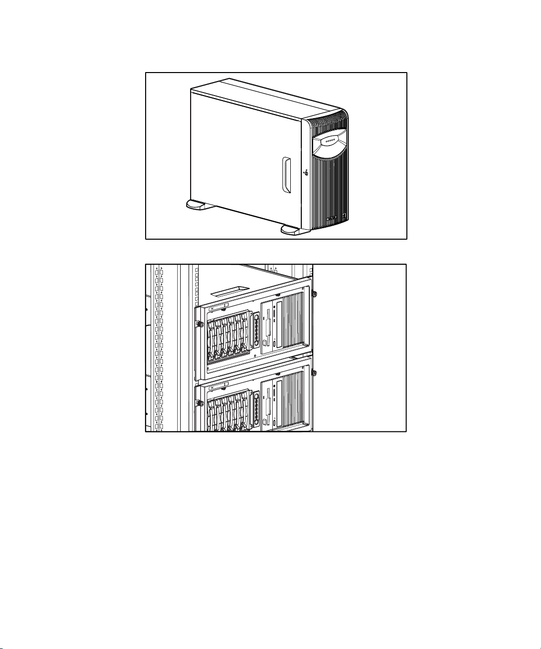
Figure 1-1. ProLiant ML350 Generation 2 tower server
Server Features 1-3
Figure 1-2. ProLiant ML350 Generation 2 rack server
Page 16

1-4 Compaq ProLiant ML350 Generation 2 Server Setup and Installation Guide
Standard Hardware Features
The following hardware features are standard on the ProLiant ML350
Generation 2 server, unless otherwise noted.
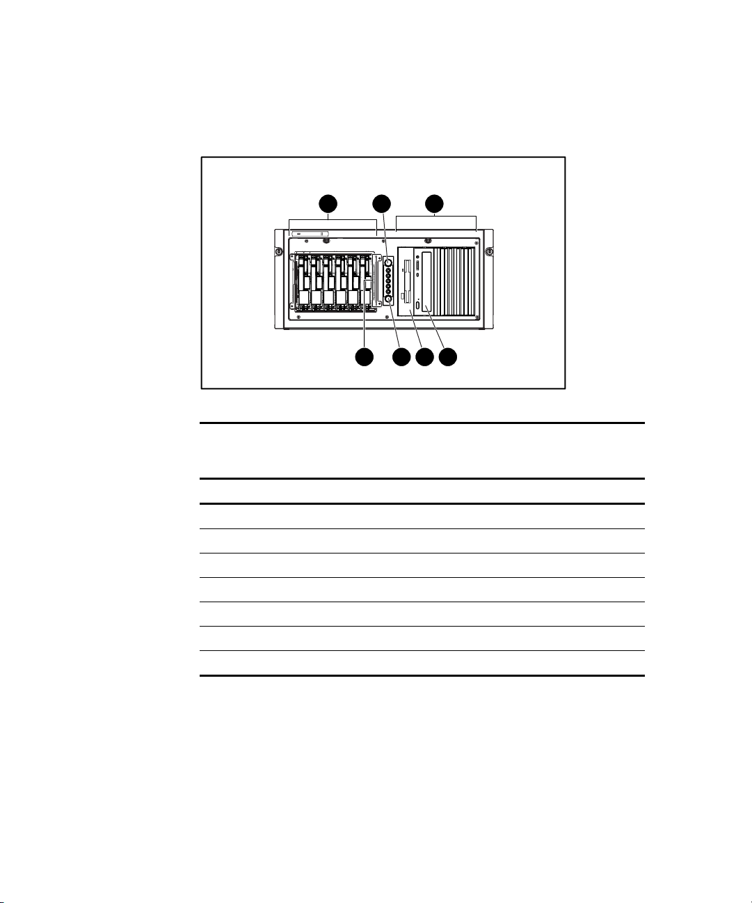
Tower Server Front Panel Components and Drive Bay Dimensions
The ProLiant ML350 Generation 2 server supports a maximum of ten internal
drives (four are intended for removable media drives and six are for hard
drives). Figure 1-3 shows the front panel components and Table 1-1 shows the
drive dimensions of the ProLiant ML350 Generation 2 server.
7
6
5
4
3
1
2
Figure 1-3. Identifying front panel components with bezel removed (tower)
Table 1-1
Tower Server Front Panel Components with Drive Bay Dimensions
Item Component Dimensions
Removable media bays 5.25 in x 1.60 in
Power button N/A
Hard drive bays 3.5 in x 1.0 in
Unit ID button N/A
LEDs N/A
Diskette drive 3.5 in x 1.0 in
CD-ROM drive 5.25 in x 1.60 in
Page 17
Rack Server Front Panel Components and Drive Bay Dimensions
Server Features 1-5
1
Figure 1-4. Identifying front panel components (rack)
2
7
3
5 4
6
Table 1-2
Rack Server Front Panel Components with Drive Bay Dimensions
Item Component Dimensions
Hard drive bays 3.5 in x 1.0 in
Unit ID button N/A
Removable media bays 5.25 in x 1.60 in
CD-ROM drive 5.25 in x 1.60 in
Diskette drive 3.5 in x 1.0 in
Power button N/A
LEDs N/A
Page 18
1-6 Compaq ProLiant ML350 Generation 2 Server Setup and Installation Guide
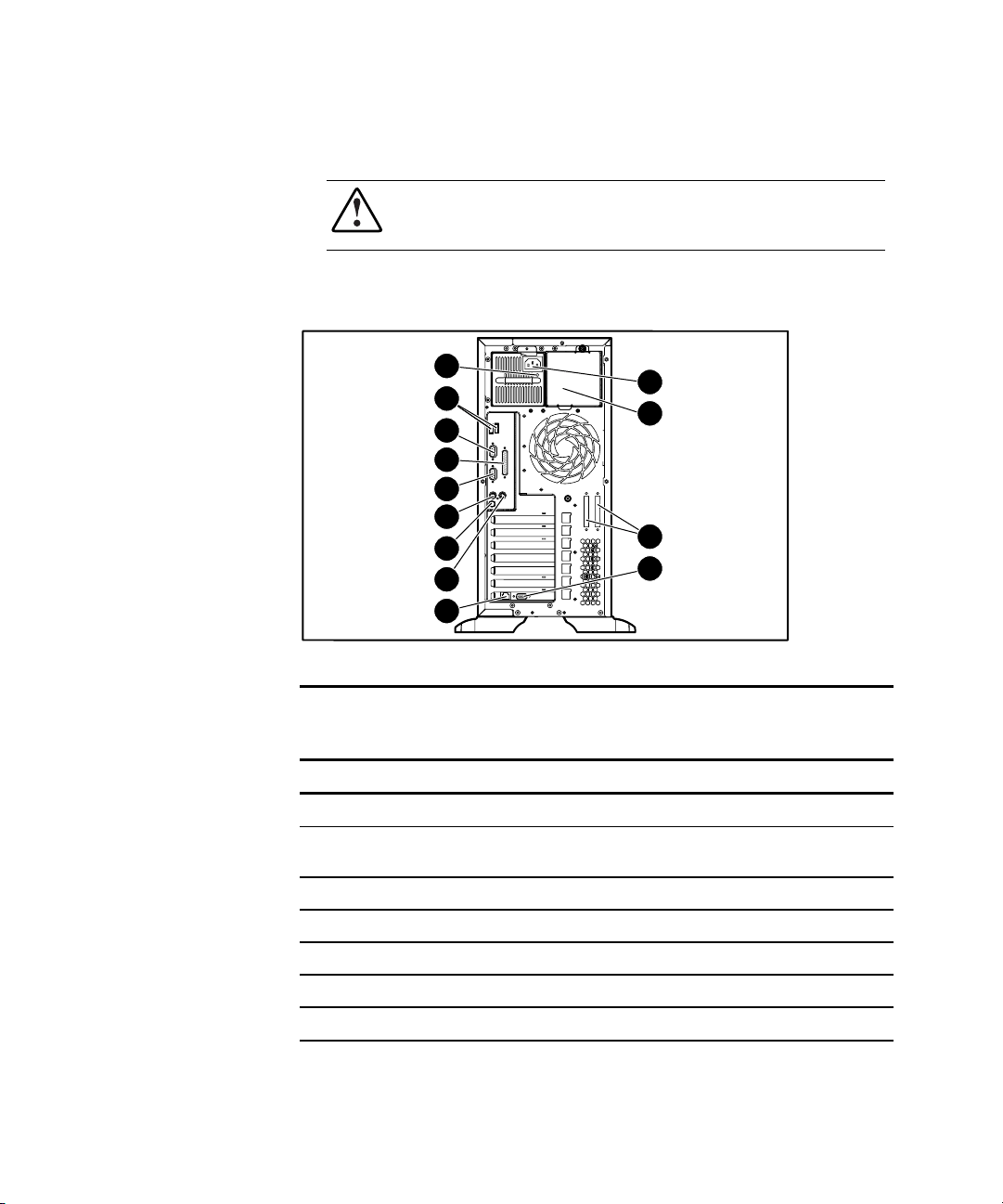
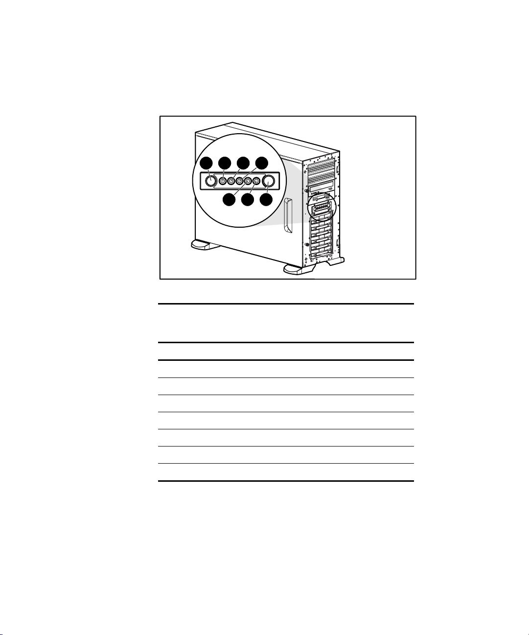
Tower Server Rear Panel Components
WARNING: This equipment is designed for connection to a grounded (earthed)
outlet. The grounding-type plug is an important safety feature. To reduce the
risk of electric shock or damage to your equipment, do not disable this feature.
Figure 1-5 and Table 1-3 show the connectors on the rear panel of the
ProLiant ML350 Generation 2 server.
13
12
11
10
9
8
7
6
5
Figure 1-5. Identifying rear panel components
1
2
3
4
Table 1-3
Rear Panel Components
Item Component Item Component
Power cord connector Keyboard connector
Optional redundant power
supply bay
SCSI connector knockouts Parallel port connector
Serial port B connector
Video connector Serial Port A connector
RJ-45 Ethernet connector USB ports
Mouse connector Power supply LED
Unit ID LED/button
Page 19
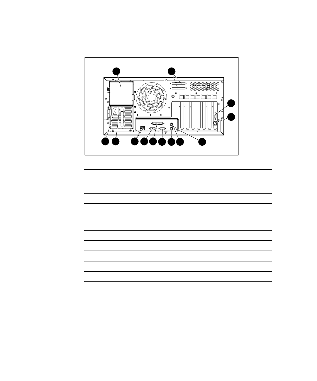
Rack Server Rear Panel Components
1 2
Server Features 1-7
3
4
910111213
Figure 1-6. Identifying rear panel components (rack)
5678
Table 1-4
Rear Panel Components
Item Component Item Component
Optional redundant power
supply bay
SCSI connector knockouts Parallel port connector
Video connector Serial port A connector
RJ-45 Ethernet connector USB ports
Unit ID LED/button Power supply LED
Mouse connector Power cord connector
Keyboard connector
Serial port B connector
Page 20
1-8 Compaq ProLiant ML350 Generation 2 Server Setup and Installation Guide
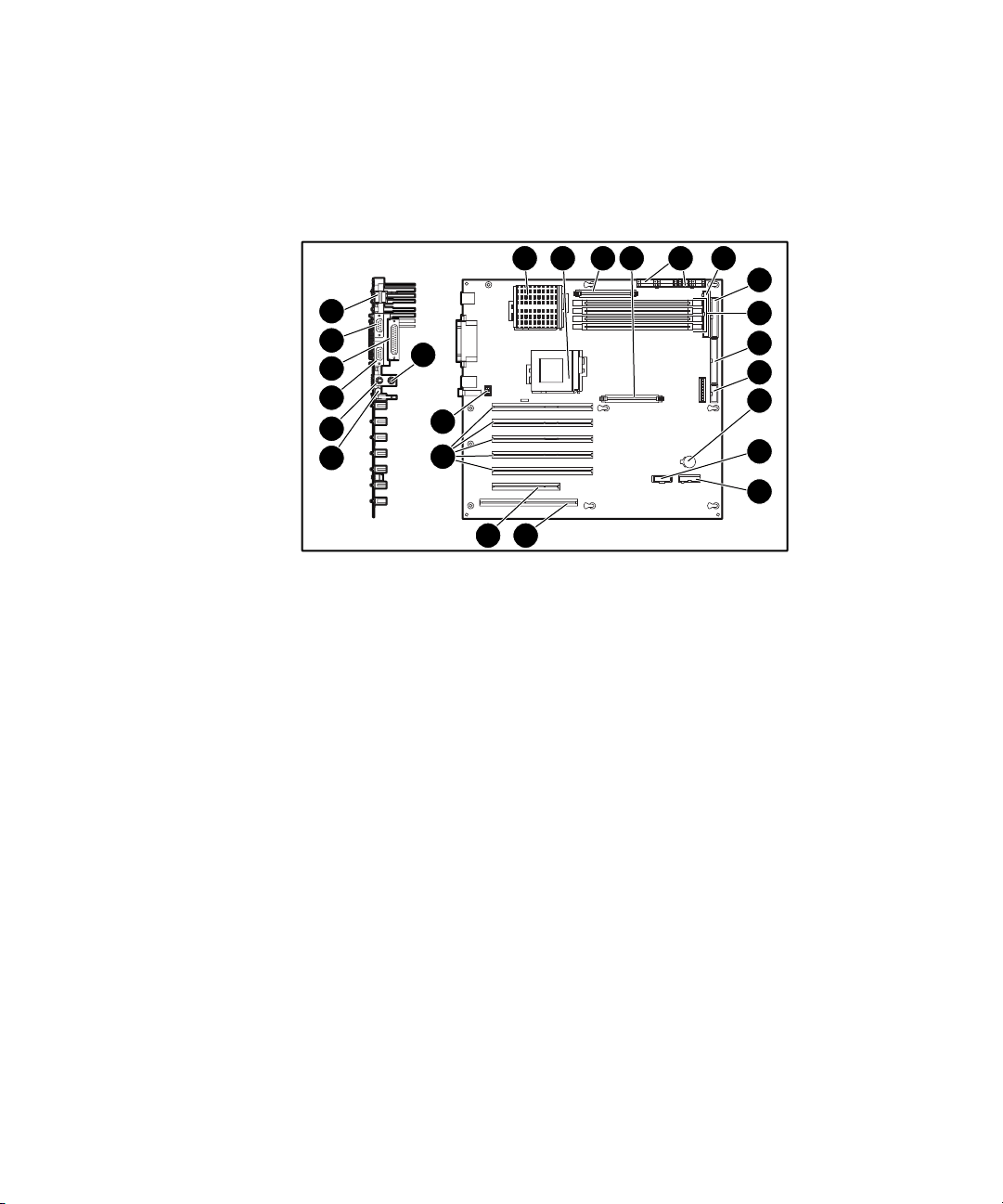
System Board Components
Figure 1-7 and Table 1-5 show the components and connectors on the system
board of the ProLiant ML350 Generation 2 server.
1 2 3 4 5 6
24
23
22
21
20
19
Figure 1-7. Identifying system board components
18
17
16
15
14
7
8
9
10
11
12
13
Page 21

Table 1-5
System Board Components
Item Component Item Component
Processor socket 1 Remote Insight Connector
(16-pin)
Processor socket 2 Server Feature Board connector
Processor Power Module 1 32-bit PCI slot
Processor Power Module 2 64-bit PCI slots
Power supply connectors System fan connector
Secondary IDE connector Mouse connector
Diskette drive connector Unit ID LED/button
DIMM slots Keyboard connector
Primary IDE connector Serial port B connector
Power button connector Parallel port connector
Server Features 1-9
Battery Serial port A connector
Remote Insight Connector
(32-pin)
Note: For information on system board LEDs, refer to Appendix E, “LED Indicators,
Switches, and Jumpers.”
USB ports
Page 22
1-10 Compaq ProLiant ML350 Generation 2 Server Setup and Installation Guide
LEDs and Buttons
Figure 1-8 shows the LEDs and buttons on the front panel of the server.
1 2 3 4
7 6 5
2
Figure 1-8. Front panel LEDs and buttons
Table 1-6
Front Panel LEDs and Buttons
Item LED/Button
Unit ID button
Unit ID LED
Internal health LED
External health LED
Power button
Power LED
NIC activity LED
Page 23

Processors and System Memory
■ Pentium III processor with integrated 512-KB Level 2 Advanced
Transfer Cache and dual-processor capability
■ Error checking and correcting (ECC) for memory error detection and
correction
■ 133-MHz Registered ECC synchronous dynamic random access
memory (SDRAM) DIMMs, upgradable to 4 GB
■ Support for up to four PC 133-MHz Registered ECC SDRAM DIMMs
■ DIMMs may be installed one at a time
Expansion Slots
■ Six expansion slots: five 64-bit PCI slots and one 32-bit PCI slot
■ PCI bus that provides peripheral transactions at a bus clock speed of up
to 33 MHz
■ 3.3-volt compatible (5-volt compatible on the 32-bit PCI slot)
Server Features 1-11
Storage Controller
■ Integrated dual-channel Wide Ultra3 SCSI controller on the PCI local
bus. The controller provides either two internal SCSI buses, two
external SCSI buses, or one internal and one external SCSI bus. This
controller performs at a maximum data transfer rate of 160 MBps.
■ Optional controller boards for RAID support, controller duplexing or
expanding available storage capacity.
Page 24

1-12 Compaq ProLiant ML350 Generation 2 Server Setup and Installation Guide
Network Interface Controller
■ Integrated Compaq Fast Ethernet 10/100 Autoswitching network
interface controller (NIC).
■ The Embedded NIC Port 1 PXE Support options allow the server to
boot to the network and attach to a PXE server with boot images. When
enabled, the NIC port is displayed in the initial program load (IPL) list.
Ports and Connectors
■ Serial (2)
■ Parallel
■ Keyboard
■ Mouse
■ USB (2)
Power Supply
■ CE Mark-compliant 350-watt optionally redundant 1+1 hot-plug power
supply with power factor correction and auto switching
Page 25
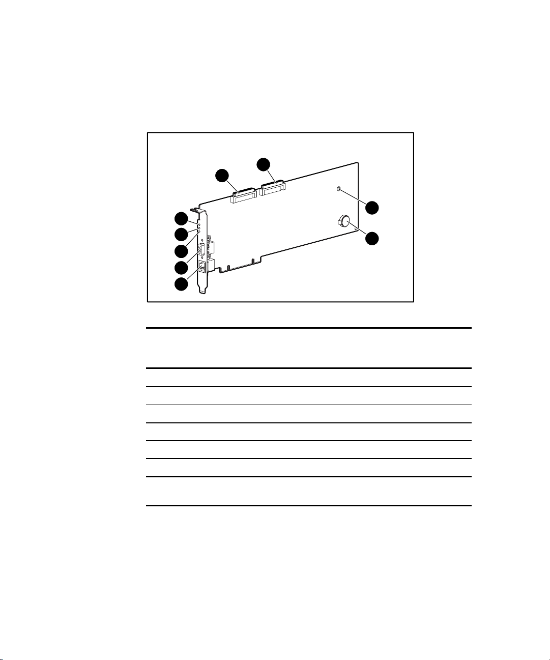
Server Feature Board Components
Figure 1-9 and Table 1-7 show the components of the ProLiant ML350
Generation 2 Server Feature Board.
2
1
9
8
7
6
5
Figure 1-9. Identifying Server Feature Board components
Server Features 1-13
3
4
Table 1-7
Server Feature Board Components
Item Component Item Component
SCSI controller channel B Video connector
SCSI controller channel A Network speed LED
NMI button Network link LED
Replaceable lithium battery (CR2032) Network activity LED
RJ-45 Ethernet connector for NIC
Note: For LED status information, refer to Appendix E, “LED Indicators, Switches, and
Jumpers.”
Page 26

1-14 Compaq ProLiant ML350 Generation 2 Server Setup and Installation Guide
Interfaces
■ Integrated Dual Channel Wide Ultra3 SCSI Controller
■ Integrated Compaq Fast Ethernet 10/100 Autoswitching Network
Interface Card (NIC)
Video
■ Integrated ATI Rage XL Video Controller providing maximum
resolution of 1280 x 1024 noninterlaced at 16.7 million colors
■ Supports SVGA, VGA, and EGA graphics resolution
■ 8-MB SDRAM video memory
Warranty
The Compaq Prefailure Warranty helps prevent unplanned shutdowns of the
system by allowing for the replacement of covered parts before they fail. The
warranty covers processors, memory, and hard drives. Compaq Insight
Manager, included with the system, must be installed for the Compaq
Prefailure Warranty to be in effect.
When Compaq Insight Manager alerts you that a component may be eligible
for Prefailure Warranty replacement, follow the onscreen instructions or
contact a Compaq authorized service provider in your area. A yellow status
indicator on the Compaq Insight Manager control panel signals that a
component is in a prefailure condition and should be replaced.
Consult the Compaq Customer Support Center or refer to the Limited
Warranty Statement included with your server for details. Certain restrictions
and exclusions apply. For additional warranty information, visit the Compaq
website at
www.compaq.com/support/
Page 27

Server Configuration and Management
The ProLiant ML350 Generation 2 server offers an extensive set of features
and optional tools to support effective server management and configuration,
including:
■ ROM Based Setup Utility (RBSU)—performs a wide range of system
configuration activities
■ ROMPaq™ utility—allows the firmware (BIOS) to be upgraded by
flashing the system ROM and provides redundant ROM support in case
of ROM corruption
■ Compaq SmartStart™ for Servers software—provides driver updates
and assisted operating system installation
■ Compaq Insight Manager—monitors fault conditions, server
performance, security, and more
■ Compaq Diagnostics Utility—tests and verifies the operation of
Compaq hardware
■ Automatic Server Recovery-2 (ASR-2)—increases server up time in the
event of a catastrophic operating system error
■ Compaq Survey Utility—allows you to keep a historical record of server
hardware and software changes in a single configuration history file
Server Features 1-15
■ Power-On Self-Test—checks firmware and assemblies to ensure that the
system is properly functioning
See Chapter 5, “Server Configuration and Utilities,” for detailed information
on each of these utilities.
Page 28

1-16 Compaq ProLiant ML350 Generation 2 Server Setup and Installation Guide
Security
Security features include:
■ Setup Password
■ Power-on Password
■ Diskette Drive Control
■ Diskette Write Control
■ Diskette Boot Override
■ Serial Interface Control
■ CD Boot Override
■ Parallel Interface Control
■ Power Switch Protection
■ Bezel Lock
Most security features are established through RBSU. For detailed information
on RBSU, see Chapter 5, “Server Configuration and Utilities,” or see the
Compaq ROM Based Setup Utility User Guide. For additional information
concerning server security features, refer to the SmartStart for Servers CD
included in the shipping box.
Page 29
Chapter 2
Overview of Server Installation
The following instructions are provided as an overview for first-time
installation of your Compaq ProLiant ML350 Generation 2 server.
WARNING: To reduce the risk of electric shock or damage to the equipment:
■ Do not disable the power cord grounding plug. The grounding plug is an
important safety feature.
■ Plug the power cord into a grounded (earthed) electrical outlet that is
easily accessible at all times.
■ Disconnect power from the server by unplugging the power cord from
either the electrical outlet or the server.
■ Do not place anything on power cords or cables. Arrange them so that no
one can accidentally step on or trip over them. Do not pull on a cord or
cable. When unplugging from the electrical outlet, grasp the cord by the
plug.
CAUTION: Electrostatic discharge (ESD) can damage electronic components. Be
sure that you are properly grounded (earthed) before beginning any installation
procedure. See Appendix B, “Electrostatic Discharge (ESD),” for more
information.
Page 30

2-2 Compaq ProLiant ML350 Generation 2 Server Setup and Installation Guide
Selecting a Site
Make sure that the installation area that you select has the following features:
■ A sturdy, level installation site that includes dedicated and properly
grounded (earthed) circuits, air conditioning, and electrostatic discharge
(ESD) protection
■ 7.6 cm (3.0 inches) clearance on all sides of server for proper ventilation in
a tower configuration
IMPORTANT: See the following section, “Installing the Rack Server,” for clearance
specifications if you are installing the ProLiant ML350 Generation 2 server into a rack
configuration.
■ A separate electrical circuit for the server
CAUTION: Protect the server from power fluctuations and temporary
interruptions with a regulating uninterruptible power supply (UPS). This device
protects the hardware from damage caused by power surges and voltage spikes
and keeps the system in operation during a power failure.
To purchase a UPS, contact your local Compaq authorized reseller or
visit the Compaq website:
www.compaq.com/showroom/
Refer to Appendix F, “Specifications,” for detailed power and environmental
site requirements.
Page 31

Installing the Rack Server
The ProLiant ML350 Generation 2 server is also available in a rack model,
immediately ready for installation. A rack conversion option kit is also
available for customers who want to convert a tower ProLiant ML350
Generation 2 server to a rack server. This section provides environmental
information required for the installation of a rack-mounted server.
Tower-to-Rack Option
Figure 2-1 shows the ProLiant ML350 Generation 2 server installed in a rack
configuration.
Overview of Server Installation 2-3
Figure 2-1. The ProLiant ML350 Generation 2 server installed in a rack
To purchase the rack conversion kit (Part Number 237045-B21), contact your
local Compaq authorized reseller or order direct from Compaq.
A selection of racks for your server can be purchased through your Compaq
authorized reseller or direct from Compaq at
www.compaq.com/storage/
Page 32

2-4 Compaq ProLiant ML350 Generation 2 Server Setup and Installation Guide
Rack Environment
To allow for servicing and adequate airflow, observe the following spatial
requirements when selecting a site for your rack-mounted server:
■ Leave a minimum clearance of 63.5 cm (25.0 inches) in front of the
rack.
■ Leave a minimum clearance of 76.2 cm (30.0 inches) behind the rack.
■ Leave a minimum clearance of 121.9 cm (48.0 inches) from the back of
the rack to the back of another rack or row of racks.
Compaq servers draw in cool air through the front door of the rack and expel
warm air through the rear door. Therefore, the front door must be adequately
ventilated to allow ambient room air to enter the cabinet, and the rear door
must be adequately ventilated to allow the warm air to escape from the
cabinet.
IMPORTANT: Do not block the ventilation openings.
When there is any vertical space in the rack not filled by a server or rack
component, the gaps between the components cause changes in airflow
through the rack and across the servers. Cover all gaps with blanking panels to
maintain proper airflow.
CAUTION: Always use blanking panels to fill empty vertical spaces in the rack.
This arrangement ensures proper airflow. Using a rack without blanking panels
results in improper cooling that can lead to thermal damage.
Compaq 9000 Series racks provide proper server cooling from flow-through
perforations in the front and rear doors that provide 64 percent open area for
ventilation. Refer to the rack documentation provided with Compaq 7000
Series racks for guidelines on meeting airflow requirements.
CAUTION: When using a Compaq 7000 Series rack, you must install the
high-airflow rack door insert [Part Number 327281-B21 (42U) and Part Number
157847-B21 (22U)] to provide proper front-to-back airflow and cooling to
prevent damage to the equipment.
Page 33

Locating Materials
Locate the following materials that were shipped with your ProLiant ML350
Generation 2 server:
■ Keyboard (not included with the rack model)
■ Mouse (not included with the rack model)
■ Power cord
■ Documentation and software packs inside the shipping box
In addition to these supplied items, you may need:
■ Torx T-15 screwdriver
■ Phillips #2 screwdriver
■ Hardware options
■ Ethernet cable
■ Operating system or application software
■ Uninterruptible power supply (UPS)
Overview of Server Installation 2-5
■ Monitor
Page 34

2-6 Compaq ProLiant ML350 Generation 2 Server Setup and Installation Guide
Installation Sequence
Observe the following statements before beginning any installation
procedures.
WARNING: To reduce the risk of electric shock or damage to the equipment:
■ Do not disable the power cord grounding plug. The grounding plug is an
important safety feature.
■ Plug the power cord into a grounded (earthed) electrical outlet that is
easily accessible at all times.
■ Disconnect power from the server by unplugging the power cord from
either the electrical outlet or the server.
■ Do not place anything on power cords or cables. Arrange them so that no
one can accidentally step on or trip over them. Do not pull on a cord or
cable. When unplugging from the electrical outlet, grasp the cord by
the plug.
CAUTION: If your server has a preinstalled operating system, prevent data loss
by configuring the server using the instructions in the following section,
“Factory-Installed Operating Systems.” If the operating system was not
preinstalled, follow the instructions in the “Operating System Purchased
Separately” section later in this chapter.
CAUTION: Before powering up the server, make sure that the power cord and
all cables have been properly connected or server data could be lost.
Page 35

Factory-Installed Operating Systems
If you ordered your server with a preinstalled operating system, everything
required to install your operating system is already on the server. Refer to the
steps provided in the Compaq Factory-Installed Operating System Software
User Guide for more information on using your operating system.
1. Review and follow the guidelines and procedures in the previous
sections of this chapter.
2. Connect the cables: keyboard, mouse, monitor, network, and power. See
the section for tower server or rack server rear panel components in
Chapter 1, “Server Features.”
WARNING: To reduce the risk of electric shock or fire, do not plug
telecommunications/telephone connectors into the network interface
controller (NIC) receptacle.
3. Locate the key and unlock the front bezel if necessary.
NOTE: A key hook is located inside the front bezel above the keylock latch. For your
convenience, you may use the key hook to store the key when it is not needed.
4. Power up the server by opening the front bezel and pressing the power
button on the front of the server .
Overview of Server Installation 2-7
1
2
Figure 2-2. Powering up the server (bezel removed for clarity)
Page 36

2-8 Compaq ProLiant ML350 Generation 2 Server Setup and Installation Guide
5. Follow the onscreen instructions to complete the preinstalled operating
system initialization process. After initialization is complete, the server
automatically goes through Power-on Self-Test (POST).
6. To manage the server, install Compaq Insight Manager, found on the
Compaq Management CD. For Compaq Management CD initialization
procedures, refer to the Server Setup and Management pack shipped
with your server.
IMPORTANT: You must install and use Compaq Insight Manager to benefit from the
Compaq prefailure warranties on processors, hard drives, and memory modules.
7. After verifying your server configuration, back up your system
configuration. Refer to the SmartStart for Servers CD for further
information on backing up your system configuration.
8. Install any additional hardware. See Chapter 3, “Hardware Options
Installation,” or the option kits, for detailed instructions on installing
internal hardware.
9. Install any application software.
10. Register your server. See the “Server Registration” section later in this
chapter for details.
This procedure completes the installation.
Page 37

Operating System Purchased Separately
If you purchased your operating system separately, install it using the
SmartStart for Servers CD. Refer to the Server Setup and Management pack
for instructions on using SmartStart. The first time the server is configured, the
SmartStart program automatically creates a necessary partition on your hard
drive. This partition cannot be used for any other purpose and is not a
traditional system partition.
Follow this sequence when installing your operating system for the first time:
1. Review all guidelines listed from the beginning of this chapter through
the “Locating Materials” section.
2. Install any hardware options if needed. See Chapter 3, “Hardware
Options Installation,” or see the options kits for detailed installation
instructions.
WARNING: To reduce the risk of electric shock or fire, do not plug
telecommunications/telephone connectors into the network interface
controller (NIC) receptacle.
3. Connect cables: keyboard, mouse, monitor, network, and power. See
rear panel components section applicable to your tower or rack server in
chapter 1 of this guide.
Overview of Server Installation 2-9
4. Locate the key and unlock the front bezel if necessary.
NOTE: A key hook is located inside the front bezel above the keylock latch. For your
convenience, you may use the key hook to store the key when it is not needed.
Page 38

2-10 Compaq ProLiant ML350 Generation 2 Server Setup and Installation Guide
5. Power up your server by pressing the power button on the front of the
server.
6. Configure your server. See “Configuring the Server” later in this chapter
for instructions.
7. Install the operating system.
8. Install Compaq Insight Manager to manage the server. For Compaq
Management CD initialization procedures, refer to the Server Setup and
Management pack shipped with your server.
IMPORTANT: You must install and use Compaq Insight Manager to benefit from the
Compaq Pre-Failure Warranties on processors, hard drives, and memory modules.
9. Install any application software needed.
10. Register your server. See “Server Registration” later in this chapter for
details.
Page 39
Configuring the Server
The server setup utility, RBSU, can be used to configure the server and
options. To initiate RBSU, press the F9 key when prompted during start up.
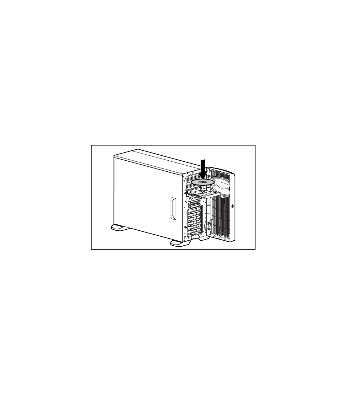
The SmartStart CD contains ROMPaq and updated drivers, and assists with
operating system installation. To use the SmartStart CD:
1. Locate the SmartStart CD in the Server Setup and Management pack.
2. After you power up the server, press the CD-ROM drive eject button.
3. Insert the SmartStart CD into the CD-ROM drive with the labeled side
up. Handle the CD by its edges, not by the flat surfaces of the disc.
Overview of Server Installation 2-11
Figure 2-3. Inserting a CD into the CD-ROM drive
4. After the server boots to the CD, the SmartStart sequence begins. Refer
to the SmartStart CD for more information.
Server Registration
For server registration information, refer to the Server Setup and Management
pack shipped with the server, or visit the Compaq website:
www.compaq.com/register
Page 40

Chapter 3
Hardware Options Installation
This chapter provides procedures for installing, removing, and replacing
hardware options in the Compaq ProLiant ML350 Generation 2 server.
CAUTION: Electrostatic discharge (ESD) can damage electronic components of
the server. Before beginning any installation procedure, make sure that you are
discharged of static electricity by briefly touching a grounded metal object.
Page 41

3-2 Compaq ProLiant ML350 Generation 2 Server Setup and Installation Guide
Preparing the Server
Chassis Components
1
2
Figure 3-1. Identifying tower and rack chassis components
3
4
5
Table 3-1
Tower and Rack Chassis Components
Item Description
Access panel
Removable media bays
CD-ROM drive
Diskette drive
Hard drive bays
Page 42

Powering Down the Server
Before installing or removing options, prepare your server by following these
steps:
CAUTION: Failure to follow these directions could result in damage to
equipment or loss of information.
1. Back up your server data and record configuration information.
2. Shut down the operating system (OS) as directed in your OS
instructions.
3. Power down the server by pressing the power button on the front of the
server.
4. Remove the power cord.
WARNING: To reduce the risk of injury from electric shock or damage to the
equipment when installing an upgrade, make sure that the server is powered
down. Remove all AC power cords to completely disconnect power from the
system. The front panel power button may not completely shut down power to
the server.
Hardware Options Installation 3-3
5. Disconnect any external equipment connections from the server.
Page 43

3-4 Compaq ProLiant ML350 Generation 2 Server Setup and Installation Guide
Removing the Bezel
To remove the bezel:
CAUTION: To prevent damage to equipment or loss of data, make sure that the
server is powered down, all cables are disconnected from the back of the
server, and the power cord is disconnected from the grounded (earthed) AC
outlet before removing the bezel.
1. Follow the steps in “Powering Down the Server” earlier this chapter.
2. If necessary, unlock the bezel using the included key .
3. Open the bezel fully to the right .
1
Figure 3-2. Unlocking the keylock and opening the bezel
2
Page 44

Hardware Options Installation 3-5
4. To remove the bezel, lift the bezel upward, and pull it away from the
chassis.
Figure 3-3. Removing the bezel
To replace the bezel, reverse the above procedure.
NOTE: When replacing the bezel, be sure that the bottom hinge points are properly
placed in the chassis before rotating the bezel back into its original position.
Removing the Access Panel in a Tower Server
To remove the access panel:
WARNING: To reduce the risk of personal injury from hot surfaces, allow the
internal system components to cool before touching them.
CAUTION: To prevent damage to equipment or loss of data, make sure that the
server is powered down, all cables are disconnected from the back of the
server, and the power cord is disconnected from the grounded (earthed) AC
outlet before removing the access panel.
CAUTION: Do not operate the server when the large access panel is removed.
This panel is an integral part of the cooling system and removing it while the
system is running may adversely affect data integrity.
Page 45

3-6 Compaq ProLiant ML350 Generation 2 Server Setup and Installation Guide
1. Remove the bezel by following the preceding steps.
2. Loosen the two thumbscrews located on the left side of the front
chassis .
3. Slide the access panel back about 1.5 cm (0.5 in) .
4. Lift and remove the panel.
NOTE: Turn the access panel over to locate the System Configuration hood label. This
label provides information on installing processor board options, configuring drives,
installing drives, LED status indicators, and setting switches.
2
1
Figure 3-4. Loosening the thumbscrews and removing the access panel
To replace the access panel, reverse steps 1 through 4.
Page 46

Removing the Access Panel in a Rack Server
To extend the server from the rack and remove the access panel:
1. Loosen the two thumbscrews that secure the chassis to the front of the
rack .
2. Slide the server out from the rack until the sliding rails lock .
1
2
Hardware Options Installation 3-7
Figure 3-5. Sliding the server out of the rack
Page 47

3-8 Compaq ProLiant ML350 Generation 2 Server Setup and Installation Guide
3. Loosen the two thumbscrews located at the top of the front chassis .
4. Slide the access panel back about 1.5 cm (0.5 in) .
5. Lift and remove the panel.
2
Figure 3-6. Removing the access panel (rack server)
1
Page 48

Removing the Removable Media Device Blanks
NOTE: The blanks must be removed from the chassis to install a storage device in its
place. The tray on the blank is used to mount non-hot plug hard drives into removable
media device bays.
To remove a removable media device blank from the front chassis:
CAUTION: Before removing a removable media device blank, make sure that
the server is powered down, all cables are disconnected from the server, and
the power cord is disconnected from the grounded (earthed) AC outlet.
1. Follow the steps in the section applicable to your tower or rack server
earlier in this chapter.
2. Push up on the drivelock to release the blanks .
3. Gently pull the blank away from the front chassis, and then remove the
blank .
Hardware Options Installation 3-9
2
1
Figure 3-7. Removing a removable media device blank
NOTE: The interior of the server may look different depending on the model purchased.
To replace a removable media device blank, reverse steps 1 through 3.
Page 49

3-10 Compaq ProLiant ML350 Generation 2 Server Setup and Installation Guide
Storage Devices
This section discusses removal and replacement procedures for the storage
devices supported by the ProLiant ML350 Generation 2 server.
Before installing a device, see “Front Panel Components and Drive Bay
Dimensions” in Chapter 1, “Server Features,” for the locations and dimensions
of the server drive bays.
CAUTION: To prevent damage to equipment or loss of information, make sure
that the server is powered down, all cables are disconnected from the back of
the server, and the power cord is disconnected from the grounded (earthed)
AC outlet before removing the access panel or front bezel.
IMPORTANT: When you add or remove a component or change a security feature, you
must reconfigure the server to recognize these changes. If the system configuration is
incorrect, your server may not work properly and you may receive error messages on the
screen.
Identifying Guide Screws
When installing drives in the removable media bay, you must install guide
screws to ensure that the drives correctly align in the drive cage. Compaq has
provided extra guide screws. They are located behind the side access panel of
the server. Some options use 5.25 M3 metric screws and some use HD 6-32
screws. The metric screws supplied by Compaq are black.
Figure 3-8. Identifying drive guide screws
NOTE: The interior of the server may look different depending on the model purchased.
Page 50

Installation Guidelines for SCSI Hard Drives
Consider the following guidelines when installing SCSI hard drives:
■ Install drives into the bays in the following order: 0, 1, 2, 3, 4, 5.
■ Assign SCSI device IDs in the following order: 0, 1, 2, 3, 4, 5.
See Figure 3-9 and Chapter 4, “Cabling Guidelines,” for additional
information.
5
4
3
2
1
0
Hardware Options Installation 3-11
Figure 3-9. Hot-plug SCSI hard drive bay configuration
Page 51

3-12 Compaq ProLiant ML350 Generation 2 Server Setup and Installation Guide
Installing and Removing a Hot-Plug Hard Drive
To install a hot-plug hard drive, first review the installation documentation that
came with the drive.
1. Follow the steps in “Removing the Bezel” earlier in this chapter to
access the hot-plug hard drive bays.
2. Slide the release latch and remove the hard drive blank .
1
2
Figure 3-10. Removing the hard drive blank
Page 52

Hardware Options Installation 3-13
3. Slide the hard drive release latch to open the ejector lever .
2
1
Figure 3-11. Opening the ejector lever
Page 53

3-14 Compaq ProLiant ML350 Generation 2 Server Setup and Installation Guide
4. Insert the hot-plug hard drive into the lowest available hot-plug drive
bay, and then close the ejector lever .
Figure 3-12. Inserting the hot-plug hard drive and closing the ejector lever
To remove a hot-plug hard drive, reverse steps 1 through 4.
IMPORTANT: A hard drive blank must be installed into any empty drive bay for the
system to properly operate.
1
2
Page 54

Installing a Device into a Removable Media Bay
The ProLiant Generation 2 server includes four removable media bays. The
lower two bays are occupied with a 3.5-inch diskette drive and an IDE
CD-ROM drive; the upper two removable media device bays are vacant. You
can install two half-height devices or one full-height device into these bays.
IMPORTANT: You must set the SCSI device ID equal to the bay number. Select a unique
SCSI device ID for each device. See Figure 3-9 for bay numbering.
Installing a Half-Height Removable Media Device
To install a 5.25-inch device:
CAUTION: To prevent damage to equipment or loss of information, make sure
that the server is powered down, all cables are disconnected from the server,
and the power cord is disconnected from the grounded (earthed) AC outlet
before removing the access panel.
1. Remove the access panel by following the steps in the section applicable
to your tower or rack server at the beginning of this chapter.
Hardware Options Installation 3-15
2. To configure the device, set the SCSI ID. You must manually set the
SCSI ID on each device to a unique value. Refer to the documentation
provided with the device for instructions on setting the SCSI ID.
3. Remove all terminating jumpers from third-party SCSI devices.
4. Install guide screws on the sides of the drive.
Page 55

3-16 Compaq ProLiant ML350 Generation 2 Server Setup and Installation Guide
5. Slide the drive into the drive bay until it clicks into place.
Figure 3-13. Installing a device mounted inside a removable media bay
NOTE: The interior of the server may look different depending on the model purchased.
6. Connect the data cable and power cable to the back of the drive.
1
Figure 3-14. Connecting the drive cables
2
Page 56

Hardware Options Installation 3-17
Installing a Tape Drive
To install a tape drive:
CAUTION: To prevent damage to equipment or loss of information, make sure
that the server is powered down, all cables are disconnected from the server,
and the power cord is disconnected from the grounded (earthed) AC outlet
before removing the access panel.
1. Remove the access panel by following the steps in the section applicable
to your tower or rack server at the beginning of this chapter.
2. Install guide screws on the sides of the drive.
3. To configure the device, set the SCSI device ID. You must manually set
the SCSI device ID on each device to a unique value in the range of
0 through 6 for each SCSI bus. Refer to the documentation provided
with the drive for instructions on setting the SCSI device ID.
4. Slide the drive into the drive bay until it clicks into place.
Figure 3-15. Installing a tape drive (DLT)
NOTE: The interior of the server may look different depending on the model purchased.
IMPORTANT: Compaq recommends installing the tape drive on a separate SCSI cable to
avoid a decrease in performance of other SCSI devices.
Page 57

3-18 Compaq ProLiant ML350 Generation 2 Server Setup and Installation Guide
5. Connect the data cable and power cable to the back of the drive.
2
1
Figure 3-16. Connecting the tape drive cables
Removing a Device from Removable Media Bay
To remove a tape drive or other device:
CAUTION: To prevent damage to equipment or loss of information, make sure
that the server is powered down, all cables are disconnected from the server,
and the power cord is disconnected from the grounded (earthed) AC outlet
before removing the access panel.
1. Remove the access panel by following the steps in the section applicable
to your tower or rack server at the beginning of this chapter.
2. Disconnect the power cable and data cable from the back of the tape
drive.
Page 58
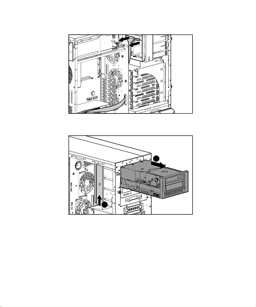
Hardware Options Installation 3-19
Figure 3-17. Disconnecting the tape drive cables
3. While pushing the drivelock up , pull the drive out of the drive bay .
2
1
Figure 3-18. Releasing the tape drive
4. Remove the guide screws on the sides of the drive.
5. Install drive blanks into any empty bays.
6. Reinstall the access panel.
Page 59

3-20 Compaq ProLiant ML350 Generation 2 Server Setup and Installation Guide
Installing an Expansion Board
Figure 3-19 and Table 3-2 identify the location of expansion slots.
1
2
3
4
5
6
Figure 3-19. Locating expansion slots
Table 3-2
Expansion Slots
Item Slot Type Slot Number
64-bit PCI 1
64-bit PCI 2
64-bit PCI 3
64-bit PCI 4
64-bit PCI 5
32-bit PCI 6
Page 60

Hardware Options Installation 3-21
To install an expansion board:
CAUTION: To prevent damage to equipment or loss of information, make sure
that the server is powered down, all cables are disconnected from the back of
the server, and the power cord is disconnected from the grounded (earthed) AC
outlet before removing the access panel.
IMPORTANT: It may be necessary to remove the slot cover next to the slot in which you
are installing a board.
1. Remove the access panel by following the steps in the section applicable
to your tower or rack server at the beginning of this chapter.
2. Loosen the thumbscrew of the expansion board retainer , and then pull
the retainer out and away from the chassis .
1
Figure 3-20. Removing the expansion board retainer
2
Page 61

3-22 Compaq ProLiant ML350 Generation 2 Server Setup and Installation Guide
3. Press on the top of the expansion slot latch , and then open the latch
toward the rear of the chassis .
4. Remove the expansion slot cover .
2
1
3
Figure 3-21. Removing the expansion slot cover
IMPORTANT: Be sure to insert expansion boards into the appropriate type of expansion
slot. The 32-bit expansion boards must be inserted into 32-bit slots or 64-bit slots, and
the 64-bit expansion boards must be inserted into 64-bit expansion slots.
Page 62

Hardware Options Installation 3-23
5. Insert the expansion board .
6. Close the expansion slot latch to secure the board .
7. Connect any cables to the expansion board.
2
1
Figure 3-22. Installing an expansion board
Page 63

3-24 Compaq ProLiant ML350 Generation 2 Server Setup and Installation Guide
8. Reinstall the expansion board retainer , and then tighten the
thumbscrew .
2
1
1
Figure 3-23. Reinstalling the expansion board retainer
9. Reinstall the access panel.
To remove an expansion board, reverse steps 1 through 8.
Page 64

Removing the Fan Baffle
To remove the baffle:
1. Remove the access panel by following the steps in the section applicable
to your tower or rack server at the beginning of this chapter.
2. Loosen the thumbscrew that secures the baffle to the fan .
3. Slide the baffle out and away from the chassis .
1
2
Hardware Options Installation 3-25
Figure 3-24. Removing the internal fan baffle
Page 65

3-26 Compaq ProLiant ML350 Generation 2 Server Setup and Installation Guide
Memory Modules
Technical Information and Important Guidelines
CAUTION: To prevent damage to equipment or loss of information, make sure
that the server is powered down, all cables are disconnected from the back of
the server, and the power cord is disconnected from the grounded (earthed)
AC outlet before removing the access panel.
CAUTION: To prevent damage to the system when handling components, see
Appendix B, “Electrostatic Discharge.”
CAUTION: When handling a memory module, be careful not to touch any of the
contacts. Doing so may damage the module.
When installing DIMMs, you must follow these guidelines:
■ DIMMs must be industry-standard 168-pin PC 133-MHz or faster
Registered SDRAM DIMMs. The SDRAM DIMMs must support CAS
Latency 2 or 3 (CL=2 or CL=3). They must also contain the mandatory
Joint Electronic Device Engineering Council (JEDEC) Serial Presence
Detect (SPD) information.
■ Do not mix ECC and non-ECC SDRAM DIMMs. If different types of
DIMMs are mixed, the system does not properly function.
■ A DIMM can be installed only one way. Be sure to match the two
key slots on the DIMM with the tab on the DIMM socket. Push the
DIMM down into the DIMM socket, ensuring that it is fully inserted and
properly seated.
Page 66

Installing a Memory Module
The ProLiant ML350 Generation 2 server supports PC 133-MHz Registered
ECC SDRAM DIMMs. Additional DIMMs are available to upgrade the
memory. The server has four DIMM sockets located on the system board.
IMPORTANT: DIMMs do not need to be installed in pairs and can be installed in any
sequence.
Hardware Options Installation 3-27
Figure 3-25. Locating DIMM sockets
Page 67

3-28 Compaq ProLiant ML350 Generation 2 Server Setup and Installation Guide
To install a DIMM:
1. Remove the access panel by following the steps in the section applicable
to your tower or rack server at the beginning of this chapter.
2. Remove the fan baffle by performing the steps in “Removing the Fan
Baffle” earlier in this chapter.
3. Press outward on both latches of the DIMM socket at the same time.
4. Insert the DIMM into the socket .
5. Return latches to the upright position .
NOTE: The latches may automatically close when the DIMM is properly inserted.
2
2
Figure 3-26. Installing a DIMM
6. Reinstall the access panel.
1
Page 68

Removing a Memory Module
To remove a DIMM:
CAUTION: Before removing the access panel, make sure that the server is
powered down, all cables are disconnected from the back of the server, and the
power cord is disconnected from the grounded (earthed) AC outlet.
1. Remove the access panel by following the steps in the section applicable
to your tower or rack server at the beginning of this chapter.
2. Remove the fan baffle by performing the steps in “Removing the Fan
Baffle” earlier in this chapter.
3. Press outward on both latches of the DIMM socket at the same time.
This step releases the DIMM and pushes it partially out of the socket .
4. Lift the DIMM from the socket .
Hardware Options Installation 3-29
1
Figure 3-27. Removing a DIMM
5. Reinstall the access panel.
1
2
Page 69

3-30 Compaq ProLiant ML350 Generation 2 Server Setup and Installation Guide
Processors and Processor Power Modules
WARNING: To reduce the risk of personal injury from hot surfaces, allow the
internal system components to cool before touching them.
CAUTION: To prevent damage to equipment or loss of information, make sure
that the server is powered down, all cables are disconnected from the back of
the server, and the power cord is disconnected from the grounded (earthed)
AC outlet before removing the access panel.
CAUTION: Static electricity can damage electronic components of the server.
Before beginning these procedures, make sure that you are discharged of static
electricity by briefly touching a grounded metal object.
To install or remove a processor or Processor Power Module (PPM), refer also
to one of the following installation sources:
■ For written instructions and illustrated installation procedures, refer to
the installation documentation that came with the option kit.
■ For an illustrated overview of the procedure, refer to the Quick Start
Poster included in the shipping box or to the System Configuration label
located on the inside of the access panel.
Installing a Processor with Heatsink
Compaq ProLiant ML350 Generation 2 servers support the installation of a
second Intel Pentium III processor for enhanced performance. Processor
option kits available for your ProLiant ML350 Generation 2 server consist of
an Intel Pentium III processor with heatsink and a Power Processor Module
(PPM).
IMPORTANT: When you install a second processor and PPM, both processors must be
the same type and speed.
IMPORTANT: Only install the specific PPM provided in the option kit with your processor.
Page 70

Hardware Options Installation 3-31
Observe the warnings and cautions provided in the option kit documentation
and in this guide. To install the processor and heatsink assembly:
1. Verify that all critical data has been backed up.
2. Ensure that your server has the most current ROM version. To update
your ROM, see the following website:
www.compaq.com/support/files/
3. Power down the server and remove the access panel as described in the
section applicable to your tower or rack server earlier in this chapter.
4. To gain access to the processor sockets, remove the internal fan baffle.
See “Removing the Fan Baffle” earlier in this chapter.
5. Locate the processor socket and corresponding PPM slot on the system
board.
1
Figure 3-28. Locating the processor sockets and Processor Power Module
(PPM) slots
2
3
4
Table 3-3
Processor Sockets and Processor Power Module Slots
Item Description
Processor socket 1 (shown)
Processor socket 2
PPM slot 1 (shown)
PPM slot 2
Page 71

3-32 Compaq ProLiant ML350 Generation 2 Server Setup and Installation Guide
6. Raise the processor socket lever to open the socket .
7. Place the processor into the socket . Use the processor socket guide
posts to align the processor.
CAUTION: Performing these steps in reverse order will cause the processor
socket on the system board to break.
2
1
Figure 3-29. Installing the processor and heatsink assembly
NOTE: The processor and sockets are keyed to fit one way only.
8. Lower the processor socket lever to secure the assembly in the socket, as
shown in Figure 3-30.
Figure 3-30. Securing the processor and heatsink assembly in the socket
Page 72

Hardware Options Installation 3-33
9. Lift the heatsink retaining clip over the rear edge of the socket and hook
underneath the socket tabs.
Figure 3-31. Seating the processor clip on the rear of the socket
10. Clasp the front of the assembly clip over the front edge of the socket .
11. Press the assembly clip down to secure the heatsink and processor
assembly in the socket .
CAUTION: Applying too much pressure on the assembly clip lever could cause
it to break. Use care when performing this step.
2
1
Figure 3-32. Securing the processor and heatsink assembly on the front of
the socket
Page 73

3-34 Compaq ProLiant ML350 Generation 2 Server Setup and Installation Guide
Installing a Processor Power Module
IMPORTANT: A new PPM must always be installed with a new processor.
To install a PPM:
1. Locate the second PPM slot and position the PPM above the slot. The
PPM is keyed to fit only one way in the slot.
2. Make sure latches are open before pressing the PPM into slot .
3. Press evenly on the PPM to insert it into the slot until latches snap up to
secure the module .
2
Figure 3-33. Installing a Processor Power Module (PPM)
1
2
Page 74

Removing a Processor
1. Remove the access panel by following the steps in the section applicable
to your tower or rack server earlier in this chapter.
2. Remove the fan baffle by performing the steps in “Removing the Fan
Baffle” earlier in this chapter.
3. Locate the processors and PPMs as shown in Figure 3-28 and Table 3-3.
4. Press one side of the heatsink retainer clip to disengage the heatsink
from the processor socket.
5. Unhook the opposite side of the heatsink retainer clip from the
processor socket.
6. Lift up the lever on the processor socket until it releases.
IMPORTANT: The lever must be perpendicular to the system board to unlock the
processor unit.
7. Remove the processor from the processor socket.
Hardware Options Installation 3-35
1
2
Figure 3-34. Removing the processor from the processor socket
8. Reinstall the access panel.
Page 75

3-36 Compaq ProLiant ML350 Generation 2 Server Setup and Installation Guide
Removing a Processor Power Module
1. Open the latches of the PPM slot .
2. Remove the PPM from the slot .
1
2
Figure 3-35. Removing a Processor Power Module (PPM)
1
Replacing Batteries
WARNING: The system board contains a lithium battery. There is a risk of fire
and chemical burn if the battery is improperly handled. Do not disassemble,
crush, puncture, short external contacts, dispose of in water or fire, or expose it
to temperatures higher than 60°C (140°F).
CAUTION: To prevent damage to equipment or loss of information, make sure
that the server is powered down, all cables are disconnected from the back of
the server, and the power cord is disconnected from the grounded (earthed) AC
outlet before removing the access panel.
CAUTION: Static electricity can damage electronic components of the server.
Before beginning these procedures, be sure that you are discharged of static
electricity by briefly touching a grounded (earthed) metal object.
The ProLiant ML350 Generation 2 has nonvolatile memory which requires
batteries to retain system information. There is a battery on the system board
and a battery on the Server Feature Board.
Page 76

Replacing the System Board Battery
If your server no longer automatically displays the correct date and time, you
may need to replace the battery that provides power to the real-time clock.
When replacing a battery, use a CR2032 3-volt lithium coin cell battery.
After you have completed the battery installation, restart the system and run
RBSU by pressing the F9 key to reconfigure your system.
To replace the lithium battery:
1. Remove the access panel by following the steps applicable to your tower
or rack server earlier in this chapter.
2. Locate the battery on the system board. See Figure 3-36 for the battery
location.
NOTE: If you have expansion boards installed, you may need to remove them to access
the battery. See “Installing an Expansion Board” earlier in this chapter.
Hardware Options Installation 3-37
Page 77

3-38 Compaq ProLiant ML350 Generation 2 Server Setup and Installation Guide
3. Press the release lever , and then slide the battery out of the holder .
1
2
Figure 3-36. Removing the battery from the system board
4. Snap the replacement battery into the holder in the proper position.
IMPORTANT: Positive polarity (+) should be positioned facing out.
5. Reinstall the access panel.
6. Run the ROM Based Setup Utility (RBSU) to reconfigure your system.
Page 78

Replacing the Server Feature Board Battery
To replace the Server Feature Board battery:
NOTE: It may be necessary to remove the Server Feature Board from the unit to replace
the battery.
1. Remove the access panel by following the steps in the section applicable
to your tower or rack server earlier in this chapter.
2. Slide the battery out of the holder.
Hardware Options Installation 3-39
Figure 3-37. Removing the battery from the Server Feature Board
3. Slide the replacement battery into the proper position.
IMPORTANT: Positive polarity (+) must be positioned facing out.
4. Replace the access panel and connect cables to the server.
5. Run RBSU to reconfigure your system after restarting by pressing the
F9 key when prompted in the lower right corner of the screen.
Page 79

3-40 Compaq ProLiant ML350 Generation 2 Server Setup and Installation Guide
Installing the Hot-Plug Redundant Power Supply
To install the hot-plug redundant power supply:
WARNING: To reduce the risk of personal injury or damage to the equipment,
the installation of power supplies should be performed only by individuals who
are qualified in servicing server equipment and trained to deal with products
capable of producing hazardous energy levels.
WARNING: To reduce the risk of personal injury from hot surfaces, observe the
thermal labels on each power supply or module.
WARNING: To reduce the risk of injury from electric shock hazards, do not
open power supplies. Refer all maintenance, upgrades, and servicing to
qualified personnel.
CAUTION: Electrostatic discharge (ESD) can damage electronic components.
Make sure that you are properly grounded (earthed) before beginning any
installation procedure.
Page 80

Hardware Options Installation 3-41
Figure 3-38. Identifying the redundant power supply bay
1. Identify the redundant power supply bay at the back of the server.
IMPORTANT: Power supplies of the ProLiant ML350 Generation 2 server are hotpluggable. When using the redundant power supply option, it is not necessary to power
down the server before removing or installing a power supply.
2. Remove the thumbscrew that secures the redundant power supply blank,
and then lift the blank from the back of the server.
WARNING: To reduce the risk of electric shock or damage to the equipment, do
not connect AC power cords to uninstalled power supplies.
3. Slide the power supply into the power supply bay, and then apply
pressure to the power supply until the release/lock lever clicks the power
supply securely into the bay.
4. Connect the AC power cord to the power supply.
5. Verify that the power supply and the redundant power supply LEDs are
green. See Appendix E, “LED Indicators, Switches, and Jumpers,” for
details.
Page 81

Chapter 4
Cabling Guidelines
This chapter provides an overview of the internal cabling of the
Compaq ProLiant ML350 Generation 2 server chassis. It also includes
information on how to cable SCSI, IDE, and removable media devices in the
system, as well as information about all critical system cabling. If external
cabling is required, refer to the documentation included with your external
storage option device.
Page 82

4-2 Compaq ProLiant ML350 Generation 2 Server Setup and Installation Guide
Storage Device Installation Guidelines
Consider the following guidelines when adding SCSI devices:
■ As a general rule, a maximum of seven devices may be added per
channel. Your server is equipped with two Wide Ultra3 SCSI channels.
■ The configuration settings on each SCSI device should be set to the
SCSI ID of the bay (Bay 0 = SCSI ID 0) that it will occupy.
■ If only one SCSI hard drive is used, it should be installed in the
lowest-numbered bay (0).
■ Be sure to remove all terminating jumpers from third-party SCSI
devices.
CAUTION: To prevent damage to the equipment, make sure that the server is
powered down, all cables are disconnected from the back of the server, and the
power cord is disconnected from the grounded (earthed) AC outlet before
installing devices.
CAUTION: Electrostatic discharge (ESD) can damage electronic components.
Make sure that you are properly grounded (earthed) before beginning any
installation procedure. See Appendix B, “Electrostatic Discharge,” for more
information.
Page 83

Identifying SCSI Components
Hot-Plug Hard Drive SCSI Cable
The SCSI cable shown in Figure 4-1 is included with the server. The SCSI
cable connects the hot-plug drive cage to the SCSI controller. The hot-plug
hard drive cage has built-in termination.
Cabling Guidelines 4-3
Figure 4-1. Identifying the hot-plug hard drive SCSI cable
Page 84

4-4 Compaq ProLiant ML350 Generation 2 Server Setup and Installation Guide
Internal SCSI Components
Before cabling the server, note the removable media and hard drive cage
locations as shown in Figure 4-2 and Table 4-1. For additional information
about installing optional SCSI devices, refer to the documentation included
with the SCSI devices.
1
5
Figure 4-2. Internal SCSI components
4
3
Table 4-1
Internal SCSI Component Locations
Number Description
Removable media area
Hard-drive cage
SCSI channel A (primary)
SCSI channel B (secondary)
SCSI knockouts
2
Page 85

Cabling Guidelines 4-5
68-to-50 pin SCSI Adapter
If installing a device that uses a Fast SCSI-2 interface, you must provide a
68-to-50 pin SCSI adapter (Compaq Part Number 199618-001), shown in
Figure 4-3. This adapter should be installed between the 50-pin interface on
the device and the 68-pin SCSI cable connected to the SCSI channel on the
Server Feature Board.
Figure 4-3. 68-to-50 pin (wide-to-narrow) SCSI adapter
Page 86

4-6 Compaq ProLiant ML350 Generation 2 Server Setup and Installation Guide
Cabling SCSI Devices in the Removable Media Area
The following steps detail the procedure for cabling an integrated Wide Ultra3
SCSI controller (channel B) to a removable media or other device:
1. Follow the steps in the sections following “Installing a Device into a
Removable Media Bay” in Chapter 3, “Hardware Options Installation.”
Make sure that the SCSI ID is uniquely set on each device.
2. Locate the SCSI cable that is attached to SCSI channel B.
3. Install the next available connector to the device .
4. Install the next available power connector to the device .
2
1
Figure 4-4. Cabling a SCSI device
Page 87

Cabling a Smart Array or Other RAID Controller
Many configurations are possible when SCSI controllers are added. This
section outlines the procedure for connecting internal hard drives to a SCSI
controller option or a Smart Array Controller and assumes that the controller
option or Smart Array Controller is already installed.
1. If hard drives and the SCSI or Smart Array Controller are not already
installed, follow the steps in the sections “Installing and Removing a
Hot-Plug Hard Drive” and “Installing an Expansion Board” in
Chapter 3, “Hardware Options Installation.”
2. Locate the SCSI cable that is connected to the Server Feature Board
SCSI controller channel A.
Cabling Guidelines 4-7
Figure 4-5. Locating the SCSI cable (SCSI channel A)
Page 88

4-8 Compaq ProLiant ML350 Generation 2 Server Setup and Installation Guide
3. Remove the SCSI cable from the SCSI channel A connector on the
system board.
4. Reconnect the SCSI cable to either the SCSI controller option or Smart
Array Controller.
Figure 4-6. Connecting a SCSI cable to a SCSI controller option or Smart
Array Controller
NOTE: Both SCSI channels on the Server Feature Board are self-terminating. If you
choose to not use one or both of the SCSI channels, you do not need to terminate the
unused channel(s).
Page 89

Installing an Internal-to-External SCSI Connector
If you are not using one or both SCSI channels (A or B) internally or you
install a SCSI or Smart Array option card, you may install an
internal-to-external SCSI connector (Compaq Part Number 159547-B21) in
the SCSI knockout locations on the rear of the chassis. To install an
internal-to-external SCSI connector, perform the following steps:
1. Using a Torx T-15 screwdriver, remove the screw holding the SCSI
knockout cover plate , and then remove the cover plate .
2. Insert the SCSI connector into the open area . Secure the external
SCSI connector to the chassis using the screws provided with the
external SCSI connector option kit .
Cabling Guidelines 4-9
1
Figure 4-7. Installing an internal-to-external SCSI connector
2
4
3
Page 90

4-10 Compaq ProLiant ML350 Generation 2 Server Setup and Installation Guide
3. Secure the internal-to-external SCSI connector cable to either internal
SCSI channel (A or B) or to the SCSI channel of an option card.
Figure 4-8. Connecting the cable to Server Feature Board SCSI channel B
NOTE: The interior of the server may look different depending on the model you
purchased.
Connecting IDE Devices to the Integrated IDE Controller
Your server includes one IDE cable (the Cable Select Cable) that can connect
up to two IDE devices to the system through the integrated IDE controller.
This cable has three clearly labeled connectors. If only one IDE device is
connected to the system, it must be secured to the cable connector labeled
Drive 0. All IDE devices in the system should have their configuration
jumpers set to “Cable Select” or “CS.”
IMPORTANT: If your network operating system is Novell NetWare, Compaq recommends
that you connect your CD-ROM to the primary IDE channel and to the Drive 0 connector on
the IDE cable.
NOTE: IDE hard drives are not supported.
Page 91

Connecting the System Fan
The system fan is an integral part of the ProLiant ML350 Generation 2 server
system design. Proper cabling of the fan helps to avoid potential server failure
and operating system error messages.
Connect the system fan to the system board as illustrated in Figure 4-9.
Figure 4-9. Connecting the system fan (baffle has been removed for clarity)
Cabling Guidelines 4-11
Page 92

Chapter 5
Server Configuration and Utilities
This chapter provides information about the following utilities and support
tools included with your Compaq ProLiant ML350 Generation 2 server:
■ ROM Based Setup Utility (RBSU)
■ ROMPaq
■ SmartStart for Servers
■ SmartStart Diskette Builder
■ Compaq Insight Manager
■ Compaq Survey Utility
■ Compaq Diagnostics Utility
■ Automatic Server Recovery-2 (ASR-2)
■ Power-On Self-Test (POST)
Page 93

5-2 Compaq ProLiant ML350 Generation 2 Server Setup and Installation Guide
ROM Based Setup Utility
RBSU performs a wide range of configuration activities, including the
following:
■ Configuring system devices and installed options
■ Viewing system information
■ Selecting the operating system
■ Selecting the primary boot controller
In addition, RBSU includes other features, which are outlined in “Using
RBSU” later in this chapter.
For information on RBSU not found in this guide, refer to the Compaq ROM
Based Setup Utility User Guide found in your documentation pack.
Navigating RBSU
To make selections within RBSU, use the following keys:
■ To access RBSU, press the F9 key during startup when prompted in the
lower right corner of the screen.
■ The arrow keys navigate through the menu system.
■ Selections are made by pressing the Enter key.
■ Selections are cancelled by pressing the Escape key.
■ Selections and changes are saved by pressing the F10 key.
Page 94

Using RBSU
RBSU is separated into a series of menu selections designed to configure
specific areas of the system. The primary menus are as follows:
■ System Options
■ IPL Boot Device
■ PCI Devices
■ Boot Controller Order
■ Date and Time
■ Automatic Server Recovery-2 (ASR-2)
■ Server Passwords
■ Server Asset Text
■ Advanced Options
■ Utility Language
Server Configuration and Utilities 5-3
NOTE: Most of the features in RBSU are not required in the setup of your server. The
options in this utility are designed to assist with specific server configuration issues.
System Options
The System Options menu configures the basic input/output (I/O) of the server
and sets the operating system. The configuration options include the operating
system, external ports, and controlling the diskette drive. The following is a
list of selections found in this menu with an explanation of each option:
■ OS Selection selects the primary operating system for the server.
Default sever settings are automatically set based on the operating
system selected.
■ Embedded COM Port X sets the configuration for the internal serial
port A or B. The configuration options include the address and interrupt
request (IRQ). This option can also disable the port.
■ Embedded NIC Port 1 PXE Support enables the Pre-boot Execution
Environment (PXE) support for NIC Port 1. The Embedded NIC Port
PXE Support option allows the server to boot to the network and attach
to a PXE server with boot images. When enabled, the NIC port is
displayed in the Initial Program Loader (IPL) list.
■ Diskette Write Control allows the user to configure the write control of
the diskette drive. It can be set to read and write or to read only.
Page 95

5-4 Compaq ProLiant ML350 Generation 2 Server Setup and Installation Guide
Diskette Boot Control enables you to have the system boot from the
■
removable media device.
■ Embedded LPT Port allows the user to enable the embedded LPT Port
at the specified resource settings or disable the option.
IPL Boot Device
The IPL Boot Device menu option configures the Initial Program Loader
(IPL) device. It controls the search order the server goes through to look for a
bootable device.
PCI Devices
The PCI Devices menu option displays and modifies the configuration of the
PCI devices installed in the server. Information for each slot is displayed and
the IRQs can be changed. Multiple PCI devices can share an interrupt.
Boot Controller Order
The Boot Controller Order menu option is used to view and assign the
current controller order.
Date and Time
The Date and Time menu option is used to set the system date and time.
Automatic Server Recovery-2
The Automatic Server Recovery-2 menu configures the Automatic Server
Recovery-2 (ASR-2) features and may include the following options:
■ ASR-2 Status enables or disables ASR-2. When set to Disabled, no
ASR-2 features function.
■ ASR-2 Timeout sets a timeout limit for resetting a server that is not
responding. When the server has not responded in the selected amount
of time, it automatically resets.
■ Thermal Shutdown enables or disables the ability of the server to
automatically power down when it reaches a dangerous temperature.
Page 96

Server Configuration and Utilities 5-5
Server Passwords
The Server Passwords menu configures the password environment of the
server. The available options are:
■ Set Admin Password sets a password to control access to the
administrative features of the server. When this password is set, the
administrative features of the server cannot be accessed without the
correct password being entered.
■ Set Power-On Password sets a password to control access to the server
during power up. When this password is set, the server cannot be
powered up without the correct password being entered.
■ Network Server Mode is a security feature that protects an unattended
network server while allowing it to run after a power interruption. When
set to Disabled, the server operates normally. When set to Enabled, the
following actions occur:
! The local keyboard does not function unless the power-on password
is entered.
! When there is not a diskette in the diskette drive, the power-on
password is bypassed, allowing the server to start.
! When there is a diskette in the diskette drive, the server does not
start unless the power-on password is entered locally.
IMPORTANT: Network Server Mode cannot be enabled until a power-on password has
been established through the Set Power-On Password menu.
■ Quicklock enables or disables the Quicklock feature. When set to
Enabled, the keyboard is locked by pressing the Ctrl+Alt+L keys. The
keyboard remains locked until the password is typed in.
IMPORTANT: If the password is disabled at the power-on key prompt, the Quicklock
password feature will remain active until the next time the system is powered up.
Page 97

5-6 Compaq ProLiant ML350 Generation 2 Server Setup and Installation Guide
Server Asset Text
The Server Asset Text menu customizes the system-specific text for the
server, including the following:
■ Set Server Information Text defines reference information for the
server, such as Server Name, Server Asset Tag, Server Primary OS,
and Other Text.
■ Set Administrator Information Text defines reference information for
the server administrator, such as Admin Name Text, Admin Phone
Number Text, Admin Pager Number Text, and Other Text.
■ Set Service Contact Text defines reference information for the service
contact of the server, such as Service Name Text, Service Phone
Number Text, Service Pager Number Text, and Other Text.
■ Serial Number allows the user to change the chassis serial number.
Advanced Options
The Advanced Options menu is used to configure advanced options of the
system. The following is a list of selections found in this menu with an
explanation of each option:
■ MPS Table Mode allows the user to change the advanced
programmable interrupt controller (APIC) table setting. This selection
should be automatically set by OS Selection, but it allows the user to
override the automatic selection.
NOTE: The latest operating systems from Microsoft, Novell, and SCO bypass the use of
IRQs and use an APIC. The APIC has been designed to address the issues associated with
limited IRQs, multiprocessor systems, and shared interrupts. If you are using the latest
operating system, you can let the system automatically configure interrupts for all devices
in the system.
■ POST Speed Up allows the user to enable or disable the quick or slow
start process. The slow start process performs a complete memory test.
■ F1 Prompt configures the server to require the user to press the F1 key
to proceed during power up when an error is encountered during the
power-up sequence.
Page 98
Server Configuration and Utilities 5-7
Redundant ROM toggles the server ROM between the current ROM
■
and the backup ROM.
■ Erase Non-Volatile Memory resets the non-volatile memory of the
server to an initial, factory state. When Yes is selected, the non-volatile
memory is erased and set to an initial, factory state.
■ Set CPU Corrected is used to indicate that a previously failed
processor has been corrected.
■ Wake Support (PME) allows the user to enable or disable Wake
Support (PME).
■ Secondary IDE Controller allows the user to enable or disable the
secondary IDE controller.
■ NMI Debug Button allows the user to disable or enable the NMI debug
button on the Server Feature Board.
Utility Language
The Utility Language option is used to set the language in which RBSU is
displayed.
ROMPaq
Using flash ROM in Compaq servers allows the firmware (BIOS) to be
upgraded with system or option ROMPaq utilities. To upgrade the BIOS,
insert a ROMPaq diskette into the diskette drive, remove power from the
system, and then power up the system again.
NOTE: See “SmartStart Diskette Builder” later in this chapter for instructions on creating
a ROMPaq diskette.
The ROMPaq utility then checks the system and provides a choice
(if more than one exists) of ROM revisions to which the system can be
upgraded. This procedure is the same for both system and option ROMPaq
utilities.
CAUTION: Do not power down during a firmware upgrade. A loss of power
during upgrade may corrupt the firmware and prevent the system from starting.
Page 99

5-8 Compaq ProLiant ML350 Generation 2 Server Setup and Installation Guide
SmartStart for Servers Software
The SmartStart for Servers CD is used to load the system software, thereby
achieving a well-integrated server and ensuring maximum dependability and
supportability. The SmartStart for Servers CD contains diagnostic utilities and
ROMPaq tools.
To install the SmartStart for Servers CD, press the F9 key to run RBSU and
configure the primary operating system. Next, follow these steps:
1. Locate the SmartStart for Servers CD in the Server Setup and
Management pack.
2. After you power up the server, press the CD-ROM drive eject button.
3. Insert the SmartStart for Servers CD into the CD-ROM drive with the
labeled side up. Handle the CD by its edges, not by the flat surfaces of
the disc.
4. When the busy indicator turns green, the SmartStart sequence begins.
Refer to the SmartStart documentation included with your server to
install the operating system, create updated driver diskettes, and run
upgrade utilities.
SmartStart Diskette Builder
The SmartStart for Servers CD contains a utility to generate support diskettes
in the event that they are needed or the software cannot be used directly from
the SmartStart for Servers CD. Support diskettes are “punched-out” from data
stored on the SmartStart for Servers CD. The support includes:
■ Array Configuration Utility (ACU)
■ Operating System support
■ Server utilities
■ Erase utility
■ System and Option ROMPaq diskettes
To run the Diskette Builder, use a workstation running Windows 95,
Windows 98, Windows NT, or Windows 2000. You also need several
1.44-MB diskettes. All data on the diskettes will be overwritten. Insert the
SmartStart CD into the workstation drive. The CD automatically runs the
Diskette Builder utility; however, if the system does not support the “auto-run”
feature, use Windows Explorer to run
[CD-ROM DRIVE]:\DSKBLDR\DSKBLDR.EXE.
Page 100

Compaq Insight Manager
Compaq Insight Manager is the Compaq application for easily managing
network devices. Compaq Insight Manager delivers intelligent monitoring and
alerting as well as visual control of your Compaq devices, and includes the
following functions:
■ Forwards server alerts and fault conditions
■ Monitors fault conditions and server performance
■ Controls server security and configuration
■ Remotely controls server
■ Initiates rapid recovery services
Documentation for Compaq Insight Manager is available on the Compaq
Management CD in [CD-ROM DRIVE]:\OVERVIEW.HLP.
IMPORTANT: You must install and use Compaq Insight Manager to benefit from the
Compaq prefailure warranties on processors, hard drives, and memory modules.
Server Configuration and Utilities 5-9
Compaq Survey Utility
Compaq Survey Utility is an online information-gathering agent for Microsoft
Windows, Novell NetWare, and Linux that collects critical hardware and
software information from various sources. If a significant change occurs
between data-gathering intervals, the previous information is marked, and the
data file is overwritten to reflect the latest configuration and changes. This file
allows you to keep a historical record of change events for server hardware
and software.
Compaq Survey Utility automatically runs at startup and on specified time
intervals. You can modify the data-gathering interval by modifying the
command-line parameters.
For more information on Compaq Survey Utility, including installation and
application procedures, refer to the Compaq Survey Utility Online Help User
Guide accessed through the Compaq website:
www.compaq.com/support/files/server/
Perform a search for “Survey Utility,” and then follow the appropriate link.
 Loading...