


ProLiant ML350
Maintenance and Service Guide
Fourth Edition (March 2002)
Part Number 122832-004
Spare Part Number 164275-001
Compaq Computer Corporation

Notice
© 2002 Compaq Information Technologies Group, L.P.
Compaq, the Compaq logo, Compaq Insight Manager, ProLiant, ROMPaq, SmartStart, Netelligent,
SoftPaq, and QuickFind are trademarks of Compaq Information Technologies Group, L.P. in the U.S.
and/or other countries. Microsoft, MS-DOS, Windows, and Windows NT are trademarks of Microsoft
Corporation in the U.S. and/or other countries.
Intel, Pentium, Celeron, and Xeon are registered trademarks of Intel Corporation in the United States
and/or other countries.
The Open Group and UNIX are trademarks of The Open Group in the U.S. and/or other countries.
All other product names mentioned herein may be trademarks of their respective companies.
Compaq shall not be liable for technical or editorial errors or omissions contained herein. The information
in this document is provided “as is” without warranty of any kind and is subject to change without notice.
The warranties for Compaq products are set forth in the express limited warranty statements accompanying
such products. Nothing herein should be construed as constituting an additional warranty.
Compaq ProLiant ML350 Maintenance and Service Guide
Fourth Edition (March 2002)
Part Number 122832-004
Spare Part Number 164275-001

Contents
About This Guide
Symbols in Text.........................................................................................................vii
Compaq Technician Notes .......................................................................................viii
Where to Go for Additional Help...............................................................................ix
Integrated Management Log ...............................................................................ix
Telephone Numbers ............................................................................................ix
Chapter 1
Illustrated Parts Catalog
Mechanical Parts Exploded View.............................................................................1-2
Mechanical Spare Parts List .....................................................................................1-3
System Components Exploded View .......................................................................1-4
System Components Spare Parts List.......................................................................1-5
Chapter 2
Removal and Replacement Procedures
Electrostatic Discharge Information.........................................................................2-2
Symbols on Equipment ............................................................................................2-2
Preparation Procedures.............................................................................................2-4
Rack Warnings .........................................................................................................2-4
Server Warnings and Precautions.............................................................................2-5
Front Bezel Door......................................................................................................2-6
Access Panel.............................................................................................................2-7
Removable Media Blank ..........................................................................................2-8
Cable Routing Diagrams ..........................................................................................2-9
System Fan Module................................................................................................2-11
Drive Bay Configuration........................................................................................2-14
Non-Hot-Plug Hard Drive ......................................................................................2-15
Non-Hot-Plug Hard Drive Cage.............................................................................2-18
Hot-Plug Hard Drive or Drive Blank .....................................................................2-20
Hot-Plug Hard Drive Cage .....................................................................................2-21
Removable Media Devices and Mass Storage Devices..........................................2-22
Expansion Slots ......................................................................................................2-25
Expansion Board (Server Feature Board)...............................................................2-26
Memory ..................................................................................................................2-28
Memory Module.....................................................................................................2-29
Memory Combinations...........................................................................................2-30
Processor ................................................................................................................2-31
Processor Terminator Module................................................................................2-33
Processor Power Module (PPM) ............................................................................2-34

iv Compaq ProLiant ML350 Maintenance and Service Guide
Removal and Replacement Procedures
continued
System Board .........................................................................................................2-35
Batteries..................................................................................................................2-37
Replacing the System Board Battery...............................................................2-38
Replacing the Server Feature Board Battery...................................................2-39
Power Supply .........................................................................................................2-40
Feet.........................................................................................................................2-41
Chapter 3
Diagnostics and Troubleshooting
Diagnostic Tools Utility Overview...........................................................................3-2
Default Configuration...............................................................................................3-4
Inspect Utility...........................................................................................................3-4
Running the Inspect Utility ...............................................................................3-4
Printing the Inspect Listing ...............................................................................3-4
Utilities Access.........................................................................................................3-5
Running Compaq Utilities.................................................................................3-5
Power-On Self-Test (POST) Error Messages...........................................................3-6
Diagnostics Software..............................................................................................3-39
Steps for Diagnostics.......................................................................................3-39
100 – 199, Primary Processor Test Error Codes .............................................3-40
200 – 299, Memory Test Error Codes.............................................................3-41
300 – 399, Keyboard Test Error Codes...........................................................3-42
400 – 499, Parallel Printer Test Error Codes...................................................3-42
500 – 599, Video Display Unit Test Error Codes............................................3-43
600 – 699, Diskette Drive Test Error Codes ...................................................3-44
800 – 899, Video Board Test Error Codes......................................................3-45
1100 – 1199, Serial Test Error Codes .............................................................3-45
1200 – 1299, Modem Communications Test Error Codes ..............................3-46
1700 – 1799, Hard Drive Test Error Codes.....................................................3-47
1900 – 1999, Tape Drive Test Error Codes.....................................................3-48
2400 – 2499, Advanced VGA Board Test Error Codes ..................................3-48
6500 – 6599, SCSI Hard Drive Test Error Codes ...........................................3-50
6600 – 6699, SCSI/IDE CD-ROM Drive Test Error Codes............................3-50
6700 – 6799, SCSI Tape Drive Test Error Codes ...........................................3-51
8600 – 8699, Pointing Device Interface Test Error Codes..............................3-51
Array Diagnostic Utility (ADU).............................................................................3-52
Starting the ADU.............................................................................................3-52
Integrated Management Log (IML)........................................................................3-63
Multiple Ways of Viewing the IML................................................................3-63
Event List ........................................................................................................3-65
Event Messages...............................................................................................3-65
Rapid Error Recovery.............................................................................................3-68
Automatic Server Recovery ............................................................................3-68
ASR Integrated Management Log (IML) Messages .......................................3-71
Storage Fault Recovery Tracking....................................................................3-73
Storage Automatic Reconstruction..................................................................3-73
Network Interface Fault Recovery Tracking...................................................3-73
Memory Fault Recovery Tracking ..................................................................3-73
ROMPaq Error Recovery Options..........................................................................3-74
ROMPaq Disaster Recovery ...........................................................................3-74
Compaq Insight Manager .......................................................................................3-76
Compaq Insight Management Software Features............................................3-76
Compaq Insight Management Software Architecture .....................................3-77

Chapter 4
Connectors, Switches, and LED Indicators
Connectors................................................................................................................4-1
System Board Components ...............................................................................4-2
Rear Panel Components ....................................................................................4-3
Server Feature Board Components....................................................................4-4
Switches ...................................................................................................................4-5
System Board Configuration Switchbank Settings ...........................................4-5
LED (Status) Indicators............................................................................................4-7
Power and Hard Drive Activity Indicators........................................................4-8
Integrated Network Controller Status Indicators...............................................4-9
Auxiliary Power Indicator...............................................................................4-10
Chapter 5
Physical and Operating Specifications
System Unit ..............................................................................................................5-2
Memory ....................................................................................................................5-3
1.44-MB Diskette Drive ...........................................................................................5-3
IDE CD-ROM Drive ................................................................................................5-4
Wide Ultra2 SCSI Hard Drives ................................................................................5-6
Compaq NC3163 Fast Ethernet Embedded NIC ......................................................5-8
Dual Channel Wide Ultra2 SCSI Adapter................................................................5-8
Contents v
Index
This maintenance and service guide is a troubleshooting guide that can be used for reference
when servicing the Compaq ProLiant™ ML350 server.
Symbols in Text
About This Guide
WARNING: To reduce the risk of personal injury from electric shock and hazardous energy
levels, only authorized service technicians should attempt to repair this equipment. Improper
repairs could create conditions that are hazardous.
These symbols may be found in the text of this guide. They have the following meanings.
WARNING: Text set off in this manner indicates that failure to follow directions in the warning
could result in bodily harm or loss of life.
CAUTION: Text set off in this manner indicates that failure to follow directions could result in
damage to equipment or loss of information.
IMPORTANT: Text set off in this manner presents clarifying information or specific instructions.
NOTE: Text set off in this manner presents commentary, sidelights, or interesting points of information.
viii Compaq ProLiant ML350 Maintenance and Service Guide
Compaq Technician Notes
WARNING: Only authorized technicians trained by Compaq should attempt to repair this
equipment. All troubleshooting and repair procedures are detailed to allow only
subassembly/module-level repair. Because of the complexity of the individual boards and
subassemblies, no one should attempt to make repairs at the component level or to make
modifications to any printed wiring board. Improper repairs can create a safety hazard.
WARNING: To reduce the risk of electric shock or damage to the equipment:
■ If the system has multiple power supplies, disconnect power from the system by
unplugging all power cords from the power supplies.
■ Do not disable the power cord grounding plug. The grounding plug is an important safety
feature.
■ Plug the power cord into a grounded (earthed) electrical outlet that is easily accessible at
all times.
CAUTION: To properly ventilate the system, you must provide at least 30.5 cm (12 inches) of
clearance at the front and back of the computer.
CAUTION: The computer is designed to be electrically grounded (earthed). To ensure proper
operation, plug the AC power cord into a properly grounded AC outlet only.
NOTE: Any indications of component replacement or printed wiring board modifications may void any
warranty.

Where to Go for Additional Help
In addition to this guide, the following information sources are available:
■ User documentation
■ Compaq Service Quick Reference Guide
■ Service training guides
■ Compaq service advisories and bulletins
■ Compaq QuickFind
■ Compaq Insight Manager
■ Compaq download facility: Call 281-518-1418
Integrated Management Log
The ProLiant ML350 server includes an integrated, nonvolatile management log that contains
fault and management information. The contents of the Integrated Management Log (IML) can
be viewed with Compaq Insight Manager or an IML Viewer for the supported operating system.
About This Guide ix
Telephone Numbers
For the name of your nearest Compaq authorized reseller:
■ In the United States, call 1-800-345-1518.
■ In Canada, call 1-800-263-5868.
For Compaq technical support:
■ In the United States and Canada, call 1-800-386-2172.
■ For Compaq technical support phone numbers outside the United States and Canada, visit
the Compaq website:
http://www.compaq.com

Chapter 1
Illustrated Parts Catalog
This chapter provides the illustrated parts breakdown and spare parts lists for the
Compaq ProLiant™ ML350 server with Pentium III processor and a 133-MHz
system bus. See Table 1-1 and Table 1-2 for the names of referenced spare parts.
1-2 Compaq ProLiant ML350 Maintenance and Service Guide
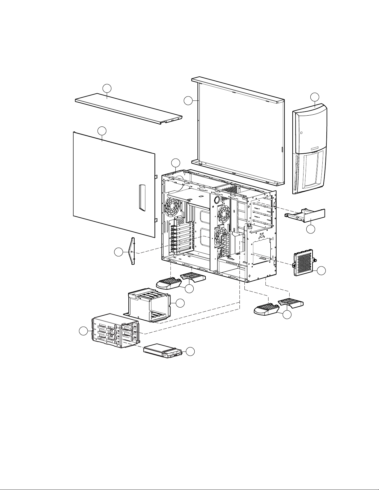
Mechanical Parts Exploded View
3c
3a
3b
1
2
8
5
Figure 1-1. Mechanical parts exploded view
7
4b
9
4a
9
6

Mechanical Spare Parts List
Item Description Spare Part Number
Chassis
1 Chassis assembly 163358-001
2 Front bezel door 164274-001
3 Cover kit 163344-001
a) Hood panel
b) Access panel
c) Top panel
d) SCSI knockout cover *
Miscellaneous
4 Non-hot-plug hard drive cage ** 163349-001
Illustrated Parts Catalog 1-3
Table 1-1
Mechanical Spare Parts List
a) Drive cage
b) Drive bay cover
5 Hot-plug hard drive cage ** 159137-001
6 Hot-plug drive blank 122759-001
7 Removable media blank *** 163345-001
8 Expansion board retainer *** 163345-001
9 Feet *** 163345-001
* Not shown
** The ProLiant ML350 server features either a hot-plug hard drive cage or a non-hot-plug hard drive cage.
*** Part of the plastics spare kit.
1-4 Compaq ProLiant ML350 Maintenance and Service Guide
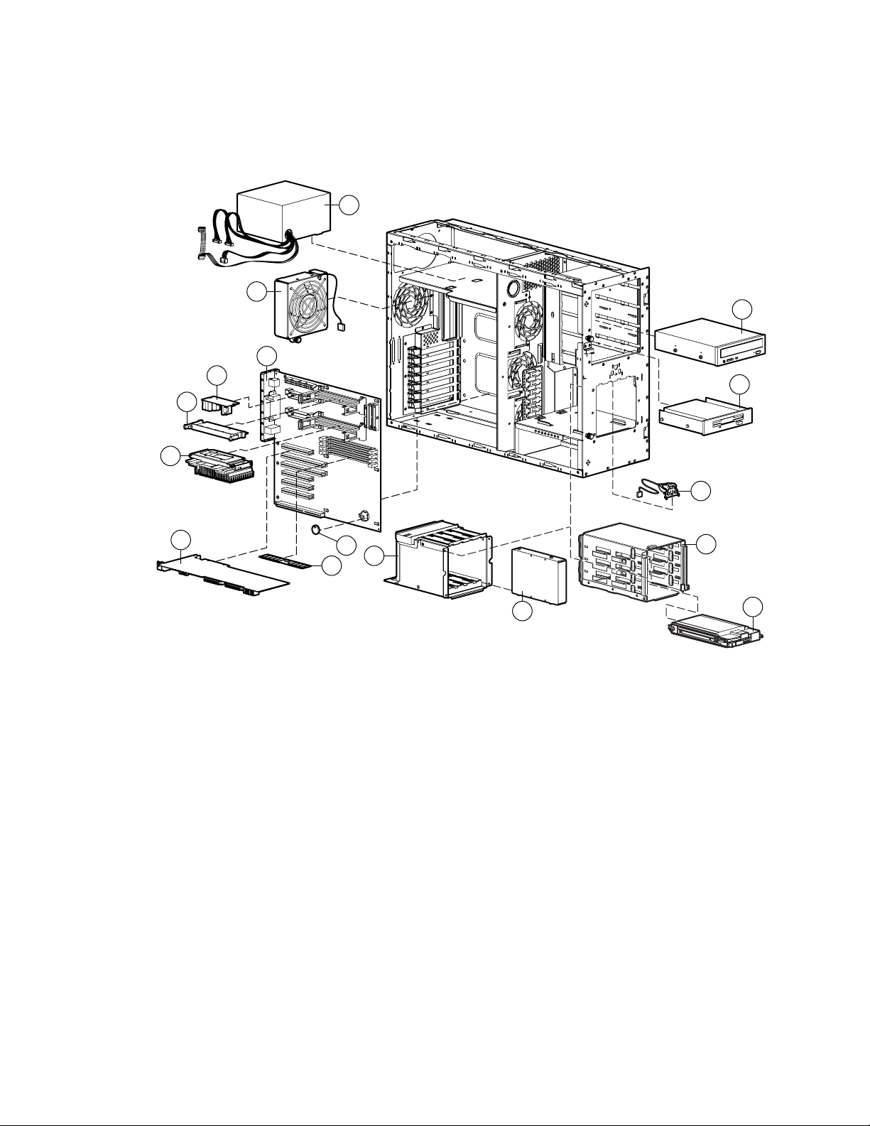
System Components Exploded View
21
10
11
22
23
24
13
14
20
12
33
30
17
Figure 1-2. System components exploded view
18
15
16

System Components Spare Parts List
System Components Spare Parts List
Item Description Spare Part Number
System Components
10 System fan module 163347-001
Boards
11 System board 163357-001
12 Server Feature Board (expansion board) 163355-001
Mass Storage Devices
13 CD-ROM drive
■ 32X IDE CD-ROM drive
■ 40X IDE CD-ROM drive *
14 Diskette drive 158601-001
Illustrated Parts Catalog 1-5
Table 1-2
163354-001
179963-001
15 Hot-plug hard drive cage ** 159137-001
15a 4-slot SCSI drive cage simplex backplane board* 387090-001
16 9.1-GB Wide Ultra2 SCSI hot-plug hard drive 122759-001
17 Non-hot-plug hard drive cage ** 163349-001
18 9.1-GB Wide Ultra2 SCSI non-hot-plug hard drive ** 349534-001
19 Hot-plug drive blank * ** 104665-001
Power
20 Power switch assembly 163350-001
21 300 W PFC power supply 163346-001
22 Processor Power Module 157825-001
23 Processor terminator module 158271-001
Options
24 Pentium III processor 600/133 EB with heatsink 166146-001
25 Pentium III processor 667/133 with heatsink * 166145-001
26 Pentium III processor 733/133 with heatsink * 164272-001
27 Pentium III processor 800/133 with heatsink * 187781-001
28 Pentium III processor 866/133 with heatsink * 187782-001
29 Pentium III processor 933/133 with heatsink * 196628-001
30 CR2032 lithium battery for system board and Server Feature Board 234556-001
* Not shown
** Also referenced in Figure 1-1 and Table 1-1
continued

1-6 Compaq ProLiant ML350 Maintenance and Service Guide
Table 1-2
System Components Spare Parts List
Item Description Spare Part Number
continued
Options continued
31 512-MB PC 133-MHz ECC Registered SDRAM DIMM * 159227-001
32 256-MB PC 133-MHz ECC Registered SDRAM DIMM * 159304-001
33 128-MB PC 133-MHz ECC Registered SDRAM DIMM 159226-001
34 64-MB PC 133-MHz ECC Registered SDRAM DIMM * 159225-001
Miscellaneous
35 Enhanced keyboard * 386209-001
36 Signal cable kit * 163353-001
a) IDE ribbon cable assembly
b) Diskette drive cable assembly
c) SMIC cable assembly
d) Removable media device SCSI cable
37 SCSI LVD cable * 163351-001
38 Miscellaneous plastics kit * 163345-001
a) PCI retainer
b) Foot, plastic, chassis
c) Removable media blank
d) 5.25-inch drive bay bezel
e) Retainer clips
f) Expansion board retainer
39 Tower-to-rack conversion kit * 164277-001
a) Front plate, rack
b) Mounting hardware kit
c) Non-hot-plug drive cage door
40 Return kit * 164270-001
41 Country kit * 164271-001
42 Maintenance and service guide * 164275-001
43 Illustrated parts map * 164276-001
* Not shown
** Also referenced in Figure 1-1 and Table 1-1

Chapter 2
Removal and Replacement Procedures
This chapter provides subassembly/module-level removal and replacement procedures for the
ProLiant ML350 server. Run the diagnostics program to verify that all components operate
properly.
To service the ProLiant ML350 server, you might need the following:
■ Torx T-15 screwdriver
■ From the Compaq SmartStart and Support Software CD:
❑ Array Diagnostics Utility (ADU)
❑ Diagnostics software
2-2 Compaq ProLiant ML350 Maintenance and Service Guide
Electrostatic Discharge Information
A discharge of static electricity can damage static-sensitive devices or microcircuitry. Proper
packaging and grounding techniques are necessary precautions to prevent damage. To prevent
electrostatic damage, observe the following precautions:
■ Transport products in static-safe containers such as conductive tubes, bags, or boxes.
■ Keep electrostatic-sensitive parts in their containers until they arrive at static-free stations.
■ Cover workstations with approved static-dissipating material. Provide a wrist strap
connected to the work surface and properly grounded (earthed) tools and equipment.
■ Keep work area free of nonconductive materials, such as ordinary plastic assembly aids
and foam packing.
■ Make sure you are always properly grounded (earthed) when touching a static-sensitive
component or assembly.
■ Avoid touching pins, leads, or circuitry.
■ Always place drives with the PCB-assembly-side down.
■ Use conductive field service tools.
Symbols on Equipment
The following symbols may be placed on equipment to indicate the presence of potentially
hazardous conditions:
This symbol in conjunction with any of the following symbols indicates the
presence of a potential hazard. The potential for injury exists if warnings are
not observed. Consult your documentation for specific details.
This symbol indicates the presence of hazardous energy circuits or electric
shock hazards. Refer all servicing to qualified personnel.
WARNING: To reduce the risk of injury from electric shock hazards, do not
open this enclosure. Refer all maintenance, upgrades, and servicing to qualified
personnel.
This symbol indicates the presence of electric shock hazards. The area
contains no user or field serviceable parts. Do not open for any reason.
WARNING: To reduce the risk of injury from electric shock hazards, do not
open this enclosure.
This symbol on an RJ-45 receptacle indicates a Network Interface Connection.
WARNING: To reduce the risk of electric shock, fire, or damage to the
equipment, do not plug telephone or telecommunications connectors into this
receptacle.
Removal and Replacement Procedures 2-3
This symbol indicates the presence of a hot surface or hot component. If this
surface is contacted, the potential for injury exists.
WARNING: To reduce the risk of injury from a hot component, allow the
surface to cool before touching.
These symbols on power supplies or systems indicate the equipment is
supplied by multiple sources of power.
WARNING: To reduce the risk of injury from electric shock, remove all power
cords to completely disconnect power from the system.
This symbol indicates that the component exceeds the recommended weight
Weight in kg
Weight in lb
for one individual to handle safely.
WARNING: To reduce the risk of personal injury or damage to the equipment,
observe local occupational health and safety requirements and guidelines for
manual material handling.
CLASS 1 LASER PRODUCT
WARNING: This label or equivalent is located on the surface of the CD-ROM
drive. This label indicates that the product is classified as a CLASS LASER
PRODUCT.
2-4 Compaq ProLiant ML350 Maintenance and Service Guide
Preparation Procedures
WARNING: Only authorized technicians trained by Compaq should attempt to repair this
equipment. Because of the complexity of the individual boards and subassemblies, no one
should attempt to make repairs at the component level or to make modifications to any printed
wiring board. Improper repairs can create a safety hazard.
CAUTION: Electrostatic discharge can damage electronic components. Be sure you are
properly grounded (earthed) before beginning any installation procedure. See “Electrostatic
Discharge” earlier in this chapter for more information.
Before beginning any removal and replacement procedure for non-hot-plug devices:
1. Power down the ProLiant ML350 server and any peripheral devices.
2. Disconnect the AC power cord from the AC outlet, and then disconnect from the server.
3. Disconnect all external peripheral devices from the server.
NOTE: If you have installed a rack upgrade kit, you must remove the ProLiant ML350 server from the
rack and place it on a sturdy table or workbench. Refer to the Compaq ProLiant ML350 Setup and
Installation Guide for instructions.
Rack Warnings
WARNING: To reduce the risk of personal injury or damage to the equipment:
■ Always load the heaviest item first, and load the rack from the bottom up. This step makes
the rack “bottom-heavy” and helps prevent the rack from becoming unstable.
■ The bottom stabilizers on the equipment must be fully extended. Be sure that the
equipment is properly supported/braced when installing options and cards.
■ Extend only one component at a time. A rack may become unstable if more than one
component is extended for any reason. Be sure that the rack is adequately stabilized
before extending a component outside the rack.
■ Before beginning work on the rack, be sure that the leveling jacks are extended to the
floor, that the full weight of the rack rests on the level floor, and that either stabilizers are
installed or multiple racks are coupled for stability.
■ Because the rack allows you to stack computer components on a vertical rather than
horizontal plane, you must take precautions to provide for rack stability and safety and to
protect both personnel and property. Heed all cautions and warnings in the installation
instructions that come with the server.
■ Tipping can cause injury or death.
WARNING: To reduce the risk of personal injury, fire, or damage to the equipment, do not
overload the AC supply branch circuit that provides power to the rack.
Server Warnings and Precautions
WARNING: To reduce the risk of personal injury from hot surfaces, allow the internal system
components to cool before touching them.
CAUTION: Protect the server from power fluctuations and temporary interruptions with a
regulating uninterruptible power supply (UPS). This device protects the hardware from damage
caused by power surges and voltage spikes and keeps the system in operation during a power
failure.
CAUTION: The server must always be operated with system unit covers on. Proper cooling is
not achieved if the system unit covers are removed.
Removal and Replacement Procedures 2-5
2-6 Compaq ProLiant ML350 Maintenance and Service Guide
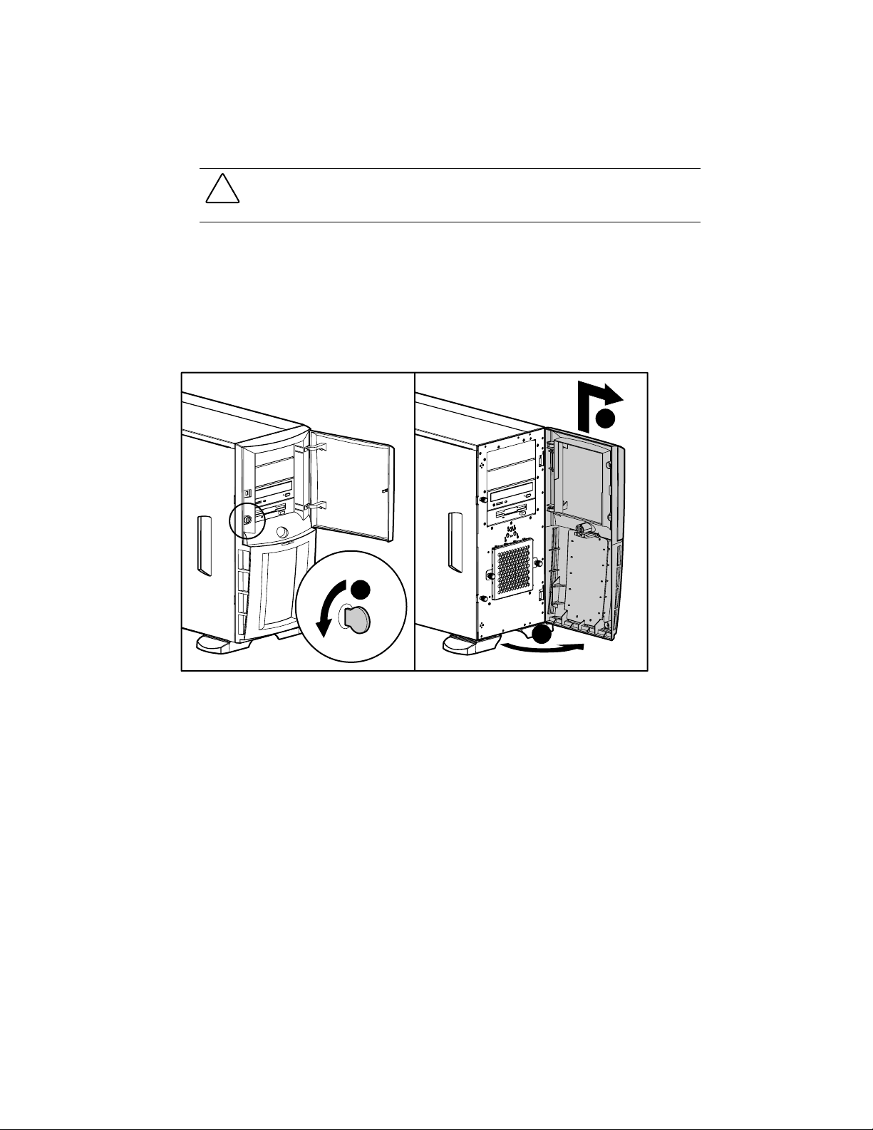
Front Bezel Door
CAUTION: Before removing the front bezel door, make sure that the server is powered down,
all cables are disconnected from the back of the server, and the power cord is disconnected
from the grounded (earthed) AC outlet.
To remove the front bezel door:
1. Complete the preparation procedures. See “Preparation Procedures” earlier in this chapter.
2. If the keylock is locked, unlock using the included key (1).
3. Open the front bezel door fully to the right (2).
4. Lift the bezel door upward (3), and then away from the chassis.
3
1
2
Figure 2-1. Removing the front bezel door
Reverse steps 1 through 4 to replace the front bezel door.
NOTE: When replacing the front bezel door, ensure that the bottom hinge points are properly placed in the chassis
before rotating the front bezel door back into its original position.
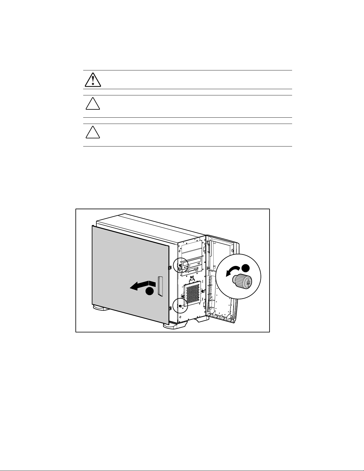
Access Panel
To remove the access panel:
1. Complete the preparation procedures. See “Preparation Procedures” earlier in this chapter.
2. Open the front bezel door. See “Front Bezel Door” earlier in this chapter.
3. Loosen the two thumbscrews (1) located on the front of the access panel.
4. Slide back the access panel (2) approximately 2.5 cm (1 inch). Then remove the panel.
Removal and Replacement Procedures 2-7
WARNING: To reduce the risk of personal injury from hot surfaces, allow the internal system
components to cool before touching them.
CAUTION: Before removing the access panel, make sure that the server is powered down, all
cables are disconnected from the back of the server, and the power cord is disconnected from
the grounded (earthed) AC outlet.
CAUTION: Do not operate the server with the large access panel removed. This panel is an
integral part of the cooling system and removing it while the system is running may cause
overheating and subsequent server shutdown.
2
Figure 2-2. Removing the access panel
Reverse steps 1 through 4 to replace the access panel.
1
2-8 Compaq ProLiant ML350 Maintenance and Service Guide
Removable Media Blank
NOTE: The removable media blank must be removed from an available removable media bay to install a
storage device for the first time.
To remove a removable media blank from the front bezel:
1. Complete the preparation procedures. See “Preparation Procedures” earlier in this chapter.
2. Remove the front bezel door. See “Front Bezel Door” earlier in this chapter.
3. Remove the access panel. See “Access Panel” earlier in this chapter.
4. While pushing up on the drivelock (1), push on the rear of the removable media blank
assembly.
5. Gently remove the removable media blank (2).
2
1
Figure 2-3. Removing the media blank
Reverse steps 1 through 5 to replace the removable media blank.
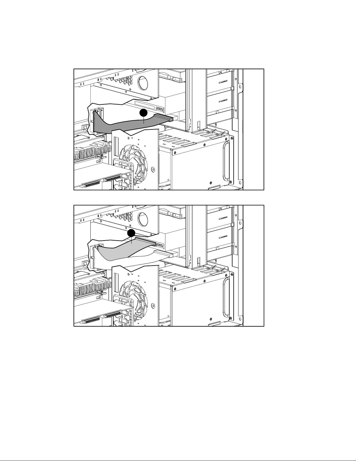
Cable Routing Diagrams
Figure 2-4. 1.44-MB diskette drive cable (1)
Removal and Replacement Procedures 2-9
1
1
Figure 2-5. IDE CD-ROM drive cable (1)
2-10 Compaq ProLiant ML350 Maintenance and Service Guide
1
2
Figure 2-6. Four-device SCSI cable (1) and power cable (2)
1
Figure 2-7. Server Management Information Cable (SMIC) (1)
System Fan Module
1
Figure 2-8. System fan module location
Removal and Replacement Procedures 2-11
Item Description
1 System fan module
Table 2-1
System Fan Location
2-12 Compaq ProLiant ML350 Maintenance and Service Guide
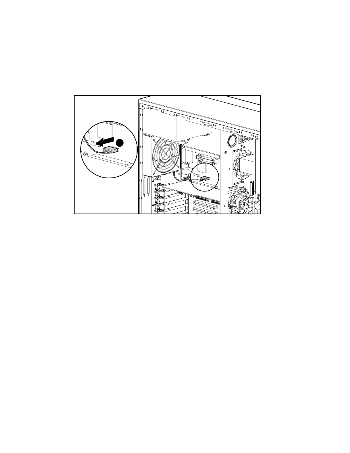
To remove the system fan module:
1. Complete the preparation procedures. See “Preparation Procedures” earlier in this chapter.
2. Remove the access panel. See “Access Panel” earlier in this chapter.
3. Disconnect the fan cable (1) from the system board.
1
Figure 2-9. Disconnecting the system fan module cable
Removal and Replacement Procedures 2-13
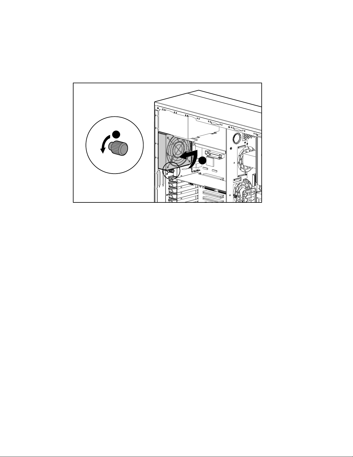
4. Loosen the thumbscrew (2) securing the fan module to the chassis.
5. Rotate the fan module (3) counterclockwise, then remove the system fan module from the
chassis.
2
3
Figure 2-10. Removing the system fan module
Reverse steps 1 through 5 to replace the system fan module.
2-14 Compaq ProLiant ML350 Maintenance and Service Guide
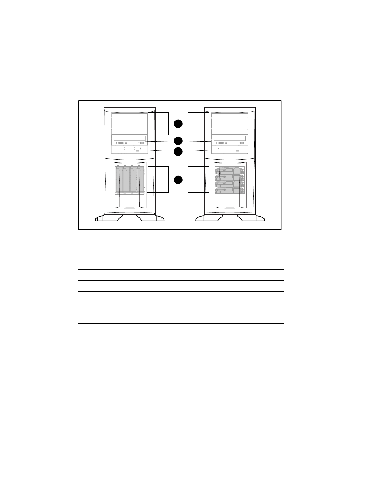
Drive Bay Configuration
The ProLiant ML350 server supports a maximum of eight internal drive bays (four are
removable media drives, four are hard drives). Figure 2-11 and Table 2-2 show the drive bay
configurations.
1
2
3
4
AB
Figure 2-11. ProLiant ML350 server drive bay configurations
Table 2-2
Drive Bay Configurations
Item A: Non-Hot-Plug Configuration B: Hot-Plug Configuration
1 Empty removable media bays Empty removable media bays
2 IDE CD-ROM drive IDE CD-ROM drive
3 1.44-MB diskette drive 1.44-MB diskette drive
4 Non-hot-plug hard drive bays Hot-plug hard drive bays
NOTE: The removable media drive bays can be occupied by any half-height device, such as a
12/24 DAT tape drive.
Non-Hot-Plug Hard Drive
To remove the non-hot-plug hard drive:
1. Complete the preparation procedures. See “Preparation Procedures” earlier in this chapter.
2. Remove the front bezel door. See “Front Bezel Door” earlier in this chapter.
3. Remove the access panel. See “Access Panel” earlier in this chapter.
4. Disconnect the data cables (1) and power cables (2) from the back of the drive.
Removal and Replacement Procedures 2-15
1
2
Figure 2-12. Disconnecting the non-hot-plug hard drive cables
2-16 Compaq ProLiant ML350 Maintenance and Service Guide
5. For systems equipped with a drive bay cover, loosen the thumbscrews (1), then remove
the drive bay cover (2).
1
Figure 2-13. Removing the drive bay cover from a non-hot-plug hard drive cage
6. While pushing in on the drivelock (1), pull the drive (2) out of the drive bay.
2
1
Figure 2-14. Removing a non-hot-plug hard drive
2

Removal and Replacement Procedures 2-17
7. With a Torx T-15 screwdriver, remove the guide screws from the hard drive.
Figure 2-15. Removing guide screws from the non-hot-plug hard drive
Reverse steps 1 through 7 to replace a non-hot-plug hard drive.

2-18 Compaq ProLiant ML350 Maintenance and Service Guide
Non-Hot-Plug Hard Drive Cage
To remove a non-hot-plug hard drive cage:
1. Complete the preparation procedures. See “Preparation Procedures” earlier in this chapter.
2. Open the front bezel door. See “Front Bezel Door” earlier in this chapter.
3. Remove the access panel. See “Access Panel” earlier in this chapter.
4. Ensure that all cables are disconnected from the hard drives.
5. Loosen the thumbscrews (1), and then remove the drive bay cover (2).
6. Remove all hard drives. See “Non-Hot-Plug Hard Drive” earlier in this chapter.
1
Figure 2-16. Removing the drive bay cover
2

Removal and Replacement Procedures 2-19
7. With a Torx T-15 screwdriver, remove the four screws (1) securing the drive cage to the
chassis.
8. Slide the drive cage (2) backward until it stops. Then pull the drive cage (3) away from the
chassis.
3
Figure 2-17. Removing a non-hot-plug hard drive cage
2
Reverse steps 1 through 8 to replace a non-hot-plug hard drive cage.
1

2-20 Compaq ProLiant ML350 Maintenance and Service Guide
Hot-Plug Hard Drive or Drive Blank
The ProLiant ML350 server is optionally available with hot-plug hard drives.
To remove a hot-plug hard drive or drive blank:
1. Complete the preparation procedures. See “Preparation Procedures” earlier in this chapter.
2. Open the front bezel door. See “Front Bezel Door” earlier in this chapter.
3. Press down the release tab (1) on the side of the drive, then pull the drive or the drive
blank (2) out of the drive bay.
2
1
Figure 2-18. Removing a hot-plug hard drive or drive blank
Reverse steps 1 through 3 to replace a hot-plug hard drive or hard drive blank.

Hot-Plug Hard Drive Cage
To remove the hot-plug hard drive cage:
1. Complete the preparation procedures. See “Preparation Procedures” earlier in this chapter.
2. Remove the front bezel door. See “Front Bezel Door” earlier in this chapter.
3. Remove the access panel. See “Access Panel” earlier in this chapter.
4. Ensure that all cables are disconnected from the hard drive cage.
5. Remove all hard drives and hard drive blanks. See “Hot-Plug Hard Drive or Drive Blank”
earlier in this chapter.
6. With a Torx T-15 screwdriver, remove the three screws (1) securing the drive cage to the
chassis.
7. Slide the drive cage (2) backward until it stops, then remove the drive cage (3) from the
chassis.
Removal and Replacement Procedures 2-21
3
Figure 2-19. Removing a hot-plug hard drive cage
2
Reverse steps 1 through 7 to replace the hot-plug hard drive cage.
1

2-22 Compaq ProLiant ML350 Maintenance and Service Guide
Removable Media Devices and Mass Storage Devices
The ProLiant ML350 server ships standard with four removable media and four mass storage
device bays. The removable media bays contain a one-third height, 1.44-MB diskette drive, a
one-half height IDE CD-ROM drive, and two open bays. The open bays may be used for a
second CD-ROM drive, tape drives, hard drives, or any SCSI device. The four mass storage
bays contain hard drives. Figure 2-20 and Table 2-3 show the standard drive configuration.
7
6
5
4
0
123
AB
Figure 2-20. Location of removable media and mass storage device bays
7
6
5
4
3
2
1
0
Table 2-3
Removable Media and Mass Storage Device Bay Descriptions
Item A: Non-Hot-Plug Configuration B: Hot-Plug Configuration
0-3 Hard drive bays Hard drive bays
4 1.44-MB diskette drive 1.44-MB diskette drive
5 IDE CD-ROM drive IDE CD-ROM drive
6 Removable media bay Removable media bay
7 Removable media bay Removable media bay

Removal and Replacement Procedures 2-23
To remove a removable media device:
1. Complete the preparation procedures. See “Preparation Procedures” earlier in this chapter.
2. Open the front bezel door. See “Front Bezel Door” earlier in this chapter.
3. Remove the access panel. See “Access Panel” earlier in this chapter.
4. Disconnect the power and the data cables (1) from the back of the removable media
device.
1
Figure 2-21. Disconnecting the removable media device cables

2-24 Compaq ProLiant ML350 Maintenance and Service Guide
5. While pushing up the drivelock (1), pull the device (2) out of the drive bay.
1
Figure 2-22. Removing the removable media device
2
Reverse steps 1 through 5 to replace a removable media device.
NOTE: It is not necessary to push up on the drivelock when replacing a removable media device. Push
the drive until it clicks into place.

Expansion Slots
Figure 2-23. Locating the expansion slots
Removal and Replacement Procedures 2-25
1
2
3
4
5
6
7
Table 2-4
Expansion Slots
Item Slot
1 32-bit PCI (Server Feature Board)
2 64-bit PCI
3 64-bit PCI
4 32-bit PCI
5 32-bit PCI
6 32-bit PCI
7 ISA

2-26 Compaq ProLiant ML350 Maintenance and Service Guide
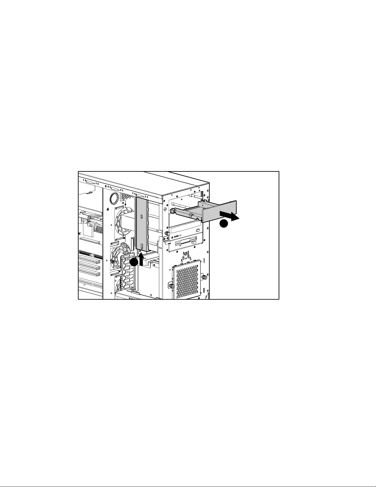
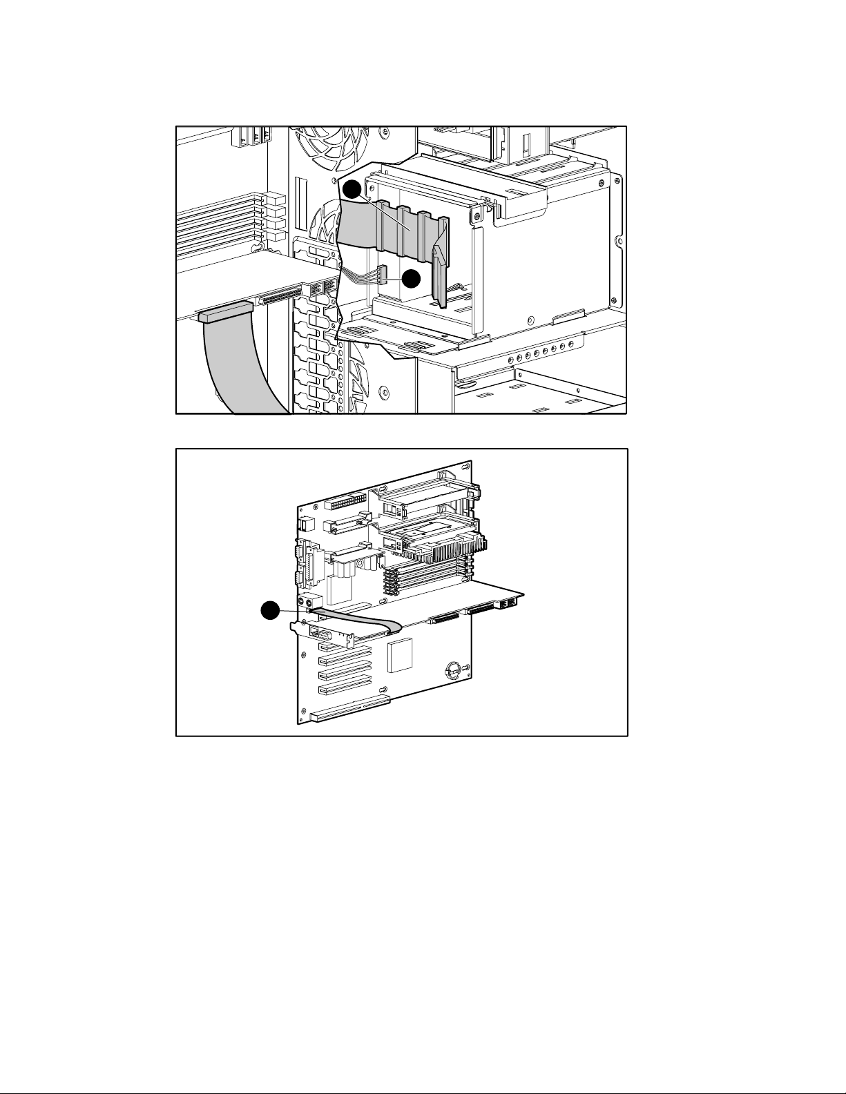
Expansion Board (Server Feature Board)
To remove an expansion board (Server Feature Board):
1. Complete the preparation procedures. See “Preparation Procedures” earlier in this chapter.
2. Remove the access panel. See “Access Panel” earlier in this chapter.
3. Disconnect any cables connected to the expansion board.
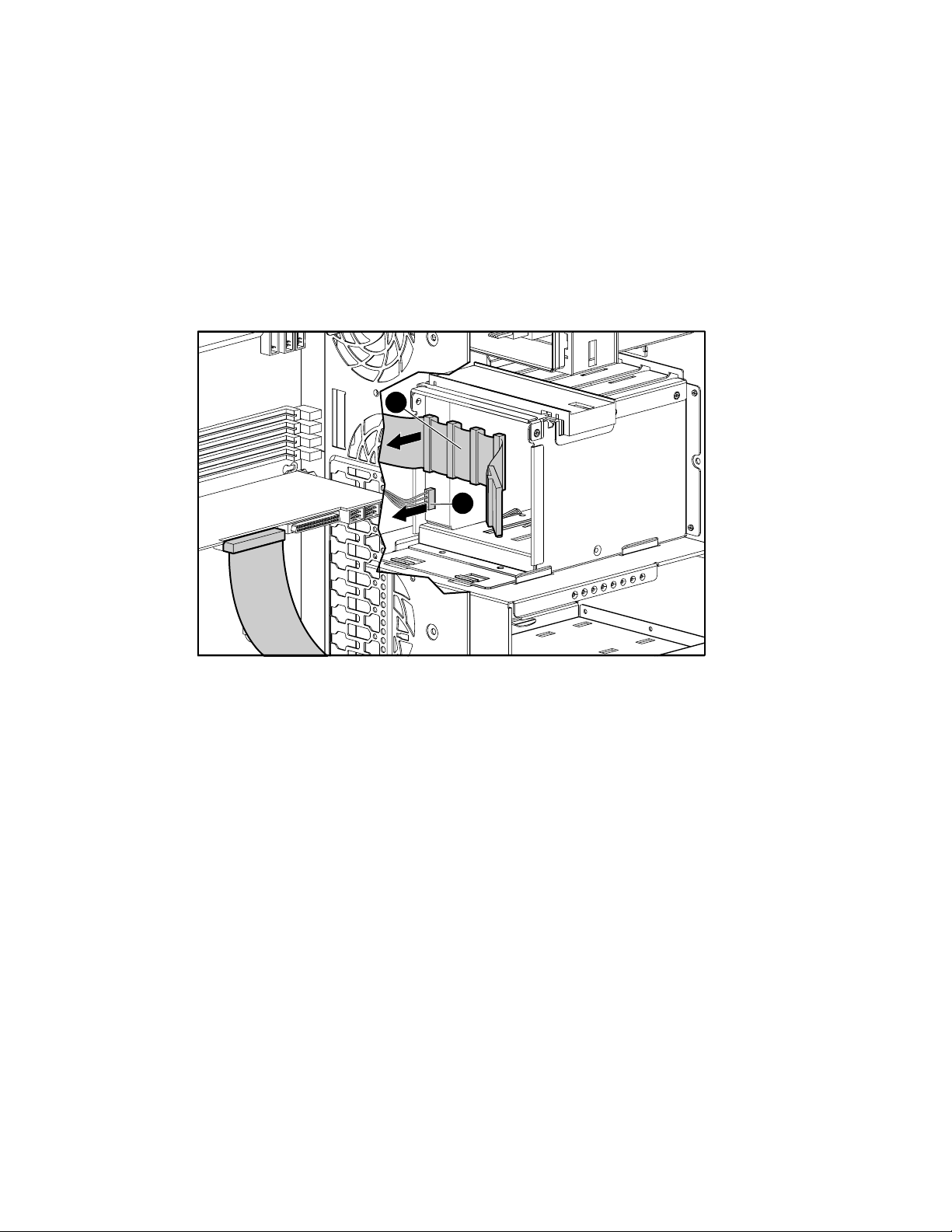
4. If an expansion board retainer is in place, loosen the thumbscrew (1) of the expansion
board retainer, then pull the retainer (2) out and away from the chassis.
1
2
Figure 2-24. Removing the expansion board (Server Feature Board) retainer

Removal and Replacement Procedures 2-27
5. Push in the expansion board slot release lever (1) to release it, then rotate the lever (2)
outward.
6. Remove the expansion board (3).
2
1
3
Figure 2-25. Removing the expansion board (server feature board)
Reverse steps 1 through 6 to replace an expansion board.

2-28 Compaq ProLiant ML350 Maintenance and Service Guide
Memory
The ProLiant ML350 server supports PC 133-MHz ECC SDRAM Dual Inline Memory
Modules (DIMMs). Additional DIMMs (64-, 128-, 256-, or 512-MB) are available to upgrade
the system memory. The server has four DIMM sockets located on the system board.
NOTE: DIMMs do not need to be installed in pairs.
1
2
3
4
Figure 2-26. DIMM socket locations
Item Description
1 DIMM socket 1
2 DIMM socket 2
3 DIMM socket 3
4 DIMM socket 4
Table 2-5
DIMM Socket Locations

Memory Module
To remove an SDRAM DIMM:
1. Complete the preparation procedures. See “Preparation Procedures” earlier in this chapter.
2. Remove the access panel. See “Access Panel” earlier in this chapter.
3. Press outward on both latches of the DIMM (1) at the same time. This action releases the
module and pushes it partially out of the socket.
4. Lift the module (2) from the socket.
Removal and Replacement Procedures 2-29
2
1
1
Figure 2-27. Removing a memory module
Reverse steps 1 through 4 to replace a memory module.

2-30 Compaq ProLiant ML350 Maintenance and Service Guide
Memory Combinations
The following guidelines MUST be followed when installing or replacing memory:
■ Use only 64-, 128-, 256-, or 512-MB ECC SDRAM DIMMs.
■ SDRAM DIMMs must be PC 133-MHz ECC.
■ Use Compaq SDRAM DIMMs only.
The recommended order of SDRAM DIMM installation is:
■ First SDRAM DIMM in socket 4
■ Second SDRAM DIMM in socket 3
■ Third SDRAM DIMM in socket 2
■ Fourth SDRAM DIMM in socket 1
Any combination of SDRAM DIMMs can be used.

Processor
Figure 2-28. Processor and Processor Power Module (PPM) slot locations
Removal and Replacement Procedures 2-31
4 1 2
3
Table 2-6
Processor and Processor Power Module (PPM) Slot Locations
Item Description
1
2
3
4
Processor slot 1 (populated with processor)
Processor slot 2 (populated with processor terminator module)
PPM slot 1 (populated)
PPM slot 2

2-32 Compaq ProLiant ML350 Maintenance and Service Guide
To remove a processor:
1. Complete the preparation procedures. See “Preparation Procedures” earlier in this chapter.
2. Remove the access panel. See “Access Panel” earlier in this chapter.
3. Push the release tabs (1) toward the center of the processor, and then gently lift the
processor (2) from the system board.
NOTE: If removing the second processor, a terminator module must be installed for proper operation.
1
1
2
Figure 2-29. Removing a processor
Reverse steps 1 through 3 to replace a processor.

Processor Terminator Module
A processor terminator module must be installed in each empty processor slot. The processor
terminator module is removed to install a second processor and PPM.
To remove the processor terminator module:
1. Complete the preparation procedures. See “Preparation Procedures” earlier in this chapter.
2. Remove the access panel. See “Access Panel” earlier in this chapter.
3. Press the release tabs (1) toward the center of the module, and then gently lift the
processor module (2) to remove it.
Removal and Replacement Procedures 2-33
1
Figure 2-30. Removing the processor terminator module
2
1
Reverse steps 1 through 3 to replace a processor terminator module.

2-34 Compaq ProLiant ML350 Maintenance and Service Guide
Processor Power Module (PPM)
Each Intel Pentium III processor supplied by Compaq comes with a Processor Power Module
(PPM) (DC-to-DC converter). A PPM is removed when it needs to be replaced or when
replacing the system board.
WARNING: To reduce the risk of personal injury from hot surfaces, allow the internal system
components to cool before touching them.
To remove a PPM:
1. Complete the preparation procedures. See “Preparation Procedures” earlier in this chapter.
2. Remove the access panel. See “Access Panel” earlier in this chapter.
3. Push both release tabs (1) outward until the tabs release, and then gently lift up the
PPM (2).
1
2
Figure 2-31. Removing a Processor Power Module (PPM) from the system board
Reverse steps 1 through 3 to replace a PPM.

System Board
To remove the system board:
1. Complete the preparation procedures. See “Preparation Procedures” earlier in this chapter.
2. Remove the access panel. See “Access Panel” earlier in this chapter.
3. Disconnect all power cables, device cables, and the power switch cable from the system
board.
4. Remove all expansion board(s), memory, processor(s), Processor Power Module(s), and
terminator modules.
5. Remove the system fan module (1). See “System Fan Module” earlier in this chapter.
1
Removal and Replacement Procedures 2-35
Figure 2-32. System fan module (1)

2-36 Compaq ProLiant ML350 Maintenance and Service Guide
6. With a Torx T-15 screwdriver, remove the four screws (1) securing the system board to
the chassis.
7. Push the system board (2) toward the front of the unit until it stops.
8. Lift up the rear part of the system board (3), and then pull it away from the chassis.
3
2
1
Figure 2-33. Removing the system board
Reverse steps 1 through 8 to replace the system board.

Batteries
Removal and Replacement Procedures 2-37
The ProLiant ML350 server has a battery on the system board and a battery on the Server
Feature Board. These batteries are required to maintain data.
The system board battery provides power to the real-time clock. When your server no longer
automatically displays the correct date and time, you may need to replace the battery.
The Server Feature Board battery stores system management information. When the system
management information no longer automatically saves, you may need to replace the Server
Feature Board battery.
When replacing either battery, use a CR2032, 3-volt, lithium, coin cell battery.
WARNING: The system board and Server Feature Board each contain a lithium battery. There
is a risk of fire and chemical burn if the battery is handled improperly. Do not disassemble,
crush, puncture, or short external contacts, dispose of in water or fire, or expose the battery to
temperatures higher than 60°C (140°F).
CAUTION: Static electricity can damage the electronic components of the server. Before
beginning these procedures, be sure you are discharged of static electricity by briefly touching
a grounded (earthed) metal object.

2-38 Compaq ProLiant ML350 Maintenance and Service Guide
Replacing the System Board Battery
To remove and replace a lithium battery on the system board:
1. Complete the preparation procedures. See “Preparation Procedures” earlier in this chapter.
2. Remove the access panel. See “Access Panel” earlier in this chapter.
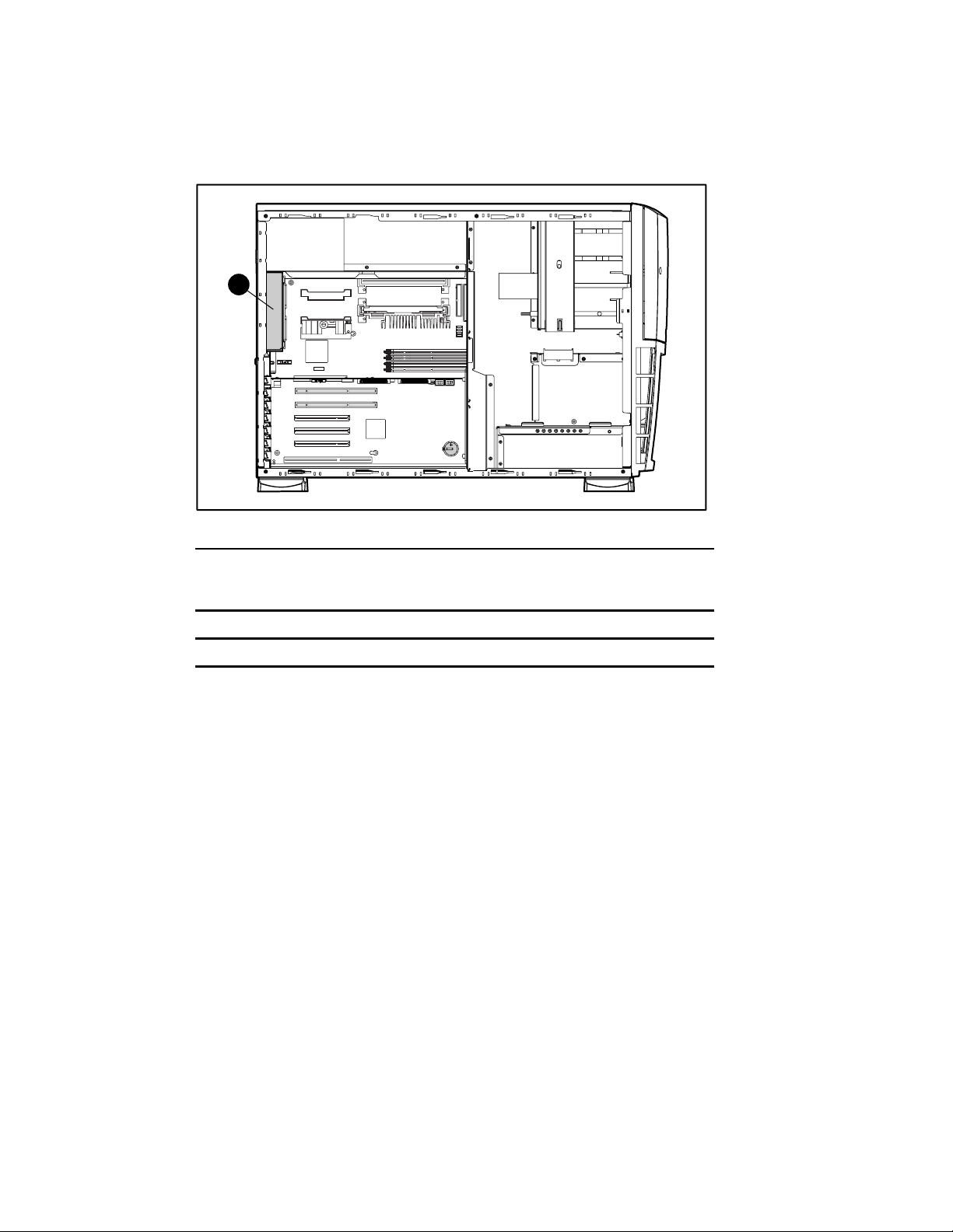
3. Locate the battery (1) on the system board.
4. Gently pull on the battery release lever while sliding the battery (2) out of its holder.
NOTE: If you have expansion boards installed, you may need to remove them in order to gain access to
the battery.
1
Figure 2-34. Locating and removing the battery from the system board
2

Replacing the Server Feature Board Battery
To remove and replace a lithium battery on the system board:
1. Complete the preparation procedures. See “Preparation Procedures” earlier in this chapter.
2. Remove the access panel. See “Access Panel” earlier in this chapter.
3. Locate the battery (1) on the system board.
4. Gently pull on the battery release lever while sliding the battery (2) out of its holder.
NOTE: If you have expansion boards installed, you may need to remove them in order to gain access to
the battery.
Removal and Replacement Procedures 2-39
1 2
Figure 2-35. Locating and removing the battery from the Server Feature Board
Reverse steps 1 through 3 to replace the battery.
IMPORTANT: The battery should be installed with the positive polarity (+ side) positioned up.

2-40 Compaq ProLiant ML350 Maintenance and Service Guide
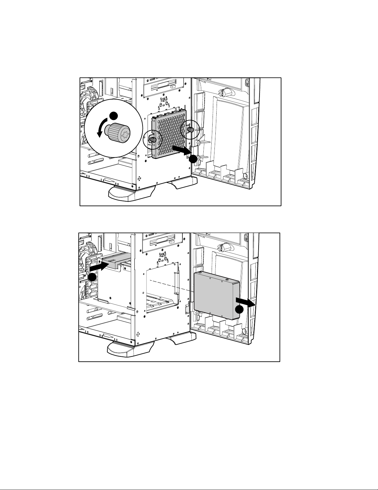
Power Supply
To remove the power supply:
1. Complete the preparation procedures. See “Preparation Procedures” earlier in this chapter.
2. Remove the access panel. See “Access Panel” earlier in this chapter.
3. Disconnect the internal power supply connectors from all system devices and the system
board.
4. With a Torx T-15 screwdriver, remove the four screws (1) securing the power supply to
the rear of the chassis.
5. Slide the power supply (2) forward until it stops, and then lift the power supply from the
chassis.
1
Figure 2-36. Removing the power supply
Reverse steps 1 through 5 to replace the power supply.
2

Feet
Removal and Replacement Procedures 2-41
To remove the feet from the chassis, one at a time:
1. Complete the preparation procedures. See “Preparation Procedures” earlier in this chapter.
2. Remove the front bezel door. See “Front Bezel Door” earlier in this chapter.
3. Place the server upside down.
4. Remove the Torx T-15 screw (1) securing each foot to the chassis.
5. Pivot each foot (2), then pull it off the base (3) of the chassis.
1
2
3
Figure 2-37. Removing the feet from the chassis
Reverse steps 1 through 5 to replace the feet.

Chapter 3
Diagnostics and Troubleshooting
This chapter describes software and firmware diagnostic tools available for Compaq server
products utilizing the Server Feature Board. The sections in this chapter are:
■ Diagnostic Tools Utility Overview
■ Default Configuration
■ Inspect Utility
■ Utilities Access
■ Power-On Self-Test (POST) Error Messages
■ Diagnostics Software
■ Array Diagnostic Utility (ADU)
■ Integrated Management Log (IML)
■ Rapid Error Recovery
■ ROMPaq Error Recovery Options
■ Compaq Insight Manager

3-2 Compaq ProLiant ML350 Maintenance and Service Guide
Diagnostic Tools Utility Overview
These tools were developed to assist in diagnosing problems, testing the hardware, and
monitoring and managing Compaq server hardware.
Table 3-1
Diagnostic Tools
Tool What it is How to run it
Compaq Diagnostics
Program
Compaq Insight
Manager
Compaq Survey
Utility
Utility to assist testing and verifying
operation of Compaq hardware. If
problems are found, Diagnostics
isolates failure(s) down to replaceable
part, whenever possible.
A client/server application used to
remotely manage Compaq hardware in
a network environment. Reports
hardware fault conditions (both failure
and pre-failure) and collects data for
reporting and graphing.
An online information gathering agent
that runs on servers, gathering critical
hardware and software information
from various sources. A utility for
servers running Microsoft Windows NT
or Novell NetWare.
If a significant change occurs between
data gathering intervals, previous
information is marked, and the survey
text file is overwritten to reflect the
latest configuration and changes since
last configuration. This action allows a
historical record of change events for
server hardware and software.
Diagnostics software is available on the
Compaq SmartStart and Support
Software CD. Create a Diagnostics
diskette from SmartStart and Support
Software CD, and run Diagnostics from
diskette.
For more information, refer to the
Compaq Management CD and the
Compaq Insight Manager User Guide.
More information on viewing and printing
the event list can be found in the
“Compaq Insight Manager” section of
this chapter.
Install Survey from SmartStart, the
Compaq Integration Maintenance Utility,
or the Compaq Management CD.
continued

Table 3-1
Diagnostic Tools
Tool What it is How to run it
continued
Diagnostics and Troubleshooting 3-3
Array Diagnostics
Utility (ADU)
A Windows-based tool designed to run
on all Compaq systems that support
Compaq array controllers. Two main
functions of ADU are to collect all
possible information about the array
controllers in the system and to
generate a list of detected problems.
Integrated
Management Log
(IML)
Compaq Inspect
Utility
A log of system events, such as system
failures or nonfatal error conditions.
View events in the IML from within:
■ Compaq Insight Manager
■ Compaq Survey Utility
■ Compaq IML Viewers
The Inspect utility provides a report
detailing system information.
BIOS Setup Utility Utility to easily configure the hardware
installed in or connected to the server.
Specifically, it can:
■ Configure PCI boards automatically
■ Manage installation of memory,
processor upgrades, and mass
storage devices such as hard
drives, tape drives, and diskette
drives
■ Store configuration information in
nonvolatile memory
■ Assist in installation of an operating
system
Use the information provided in “Array
Diagnostics Utility (ADU)” later in this
chapter.
The IML requires Compaq operating
system-dependent drivers. Refer to the
Support Software CD for instructions on
installing the appropriate drivers.
The Inspect utility can be run from either
the main menu of the System
Configuration Utility or the Compaq
Diagnostics Program.
The BIOS Setup Utility is loaded during
POST if the F10 key is pressed. When
“F10-Setup” displays in the lower right
corner of the screen, press the F10 key
to initiate the utility.

3-4 Compaq ProLiant ML350 Maintenance and Service Guide
Default Configuration
When the system is first powered up, the system ROM detects the unconfigured state of the
hardware and provides default configuration settings for most devices. By providing this
initialization, the system can run Diagnostics and other software applications before running the
normal SmartStart and OS Installation programs.
Select the primary operating system in the BIOS Setup Utility before running or installing an
OS.
Inspect Utility
The Inspect Utility provides configuration information such as the contents of the operating
system startup files, the current memory configuration, the ROM version, and Integrated
Management Log information. It operates with MS-DOS emulation mode of OS/2.
Running the Inspect Utility
1. Power the server down, then back up, then press F10 when the cursor appears in the upper
right corner of the screen.
2. At the main menu, select Diagnostics and Utilities.
3. Press Enter.
4. Select Inspect Computer and press Enter.
NOTE: If Diagnostics is not installed on the hard drive, System Configuration prompts you to insert the
Diagnostics diskette in drive A.
5. Follow the instructions.
Printing the Inspect Listing
Select Print on the Inspect screen to print a copy of the Inspect listing. Keep a copy of the listing
with each server for later reference.

Utilities Access
The SmartStart and Support Software CD contains the SmartStart program and many of the
Compaq utilities needed to maintain the system, including:
■ Array Configuration Utility (ACU)
■ Erase Utility
■ Array Diagnostic Utility (ADU)
■ ROMPaq Firmware Upgrade Utilities
■ Compaq Diagnostics
CAUTION: To avoid data loss to the entire system, do not select the Erase Utility when running
the SmartStart and Support Software CD.
Running Compaq Utilities
Compaq Utilities may be run from diskette or from the SmartStart and Support Software CD.
Running the Utilities from Diskette
■ Run the utilities from their individual diskettes. If you have a utility diskette newer than
the version on the SmartStart and Support Software CD, use that diskette.
Diagnostics and Troubleshooting 3-5
■ Create a diskette version of the utility from the SmartStart and Support Software CD.
To create diskette versions of the utilities from the CD:
1. Start the SmartStart and Support Software CD.
2. From the System Utilities screen, select Create Support Software Disks, and then select
Next.
3. Select the diskette you would like to create from the list, and then follow the instructions
on the screen.
Running the Utilities from the SmartStart and Support Software CD
IMPORTANT: Only the Array Configuration Utility (ACU) and the Array Diagnostic Utility (ADU) can be
executed from the SmartStart and Support Software CD. All other utilities must be executed from
diskette.
To run these utilities directly from the SmartStart and Support Software CD:
1. Start the SmartStart and Support Software CD.
2. From the System Utilities screen, select the utility you wish to run, and then select Next.

3-6 Compaq ProLiant ML350 Maintenance and Service Guide
Power-On Self-Test (POST) Error Messages
The Power-On Self-Test (POST) is a series of diagnostic tests that runs automatically on
Compaq computers when the system is powered up. POST checks firmware and assemblies to
ensure that the computer system is functioning properly.
If POST finds an error in the system, an error condition is indicated by an audible or visual
message. If an error code displays on the screen during POST or after resetting the system,
follow the instructions in the Table 3-2. The error messages and codes listed include all codes
generated by Compaq products. Your system generates only the codes that are applicable to
your configuration and options.
NOTE: Many of the actions listed require you to run Diagnostics or the server setup utility appropriate to
your server. Steps for running these utilities are also provided in the Compaq Servers Troubleshooting
Guide.

Diagnostics and Troubleshooting 3-7
Table 3-2
POST Error Messages
Error Code Audible Beeps Probable Source of
Problem
A Correctable
Memory Error
occurred prior to
this power up
A Critical Error
occurred prior to
this power up
Beeps only 2 long No valid memory is
None A memory module
has experienced an
error that, while
recoverable, has
generated a
predictive failure
warning.
None A catastrophic
system error, which
caused the server to
crash, has been
logged.
present in the
system.
Action
Run Diagnostics to identify the failed
memory module, and then replace it.
Run Diagnostics. Replace failed
assembly as indicated.
1. If no memory modules are
present, install at least one
memory module to conform to
minimum hardware configuration
specifications.
2. Reseat all installed memory
modules.
3. If the system contains more than
one memory module, remove one
module, and restart the server,
repeating as needed to isolate the
bad memory module.
Beeps only 2 long, 2 short The power has
cycled because the
temperature is too
hot. The processor
fan is not installed,
or is not spinning.
Critical Fan Failure
Detected –
System Shutting
Down
System Halted
None A critical fan is not
spinning.
Check fans.
1. Check fans.
2. Check fan cable connections.
continued

3-8 Compaq ProLiant ML350 Maintenance and Service Guide
Table 3-2
POST Error Messages
Error Code Audible Beeps Probable Source of
continued
Problem
Action
ECC Multiple Bit
Error Detected in
DIMM:
FATAL ROM
ERROR: The
System ROM is
not properly
programmed.
Initialization
failure.
Re-seat the
processor and
Processor Power
Module before
attempting
replacement
Invalid electronic
serial number
No SCSI Devices
Detected
Non-System disk
or disk error
None A memory module
failure generated a
multiple bit error that
could not be
corrected.
1 long, 1 short The System ROM is
not properly
programmed.
None Processor was not
fully seated.
A processor internal
failure occurred.
None Serial number in
BIOS is incorrect.
None No SCSI devices are
connected to the
boot controller.
None No bootable disk
partition was found
on the boot drive.
Run Diagnostics and replace failed
memory module as indicated.
Flash the ROM or replace the physical
ROM part.
1. Reseat the processor.
2. Replace the processor if the failure
recurs.
Run server setup utility to program
serial number.
Verify configuration. Check SCSI cable,
attached drives, and SCSI IDs.
1. Remove diskette from diskette
drive.
2. Check controller order in server
setup utility.
3. Check boot order in server setup
utility.
4. Reinstall operating system.
Parity Check 2 None A PCI device
generated a parity
error 2.
(RESUME – F1 key)
None As indicated to
continue.
Remove recently added PCI adapters.
Add the adapters again one at a time to
determine which is generating errors.
Replace the failed device.
Press F1.
continued

Table 3-2
POST Error Messages
Error Code Audible Beeps Probable Source of
continued
Problem
Diagnostics and Troubleshooting 3-9
Action
(Run System
Configuration Utility
– F10 key)
Unsupported
Processor
Detected System
Halted
101-ROM Error 1 long, 1 short System ROM
101-I/O ROM Error None Options ROM
102-System
Board Failure
104-ASR-2 Timer
Failure
105-Current
System ROM is
corrupt – now
booting redundant
System ROM
162-System
Options Not Set
None A configuration error
occurred during
POST.
1 long, 1 short Processor not
supported by current
system ROM.
checksum.
checksum.
None 8237 DMA
controllers, 8254
timers, and so on.
None System board failure. Run Diagnostics. Replace failed
2 long Nonbooted ROM
image is corrupted.
2 short Configuration
incorrect.
Press F10 to run server setup utility.
Check documentation for supported
processors. If supported, remove the
processor and update system to latest
ROM, then reinstall processor.
Run Diagnostics. Replace failed
assembly as indicated.
Run Diagnostics. Replace failed
assembly as indicated.
Replace the system board. Run the
Compaq server setup utility.
assembly as indicated.
Flash the ROM utilizing ROMPaq. Refer
to the ROMPaq Disaster Recovery
section of this guide.
Run the server setup utility and correct.
163-Time & Date
Not Set
164-Memory Size
Error
172-Configuration
Non-volatile
Memory Invalid
173-Slot ID
Mismatch
2 short Invalid time or date
in configuration
memory.
2 short Configuration
memory incorrect.
None Nonvolatile
configuration
corrupted.
None Board replaced,
configuration not
updated.
Run the server setup utility and correct.
Run the server setup utility and correct.
Run the server setup utility and correct.
Run the server setup utility and correct.
continued

3-10 Compaq ProLiant ML350 Maintenance and Service Guide
Table 3-2
POST Error Messages
Error Code Audible Beeps Probable Source of
continued
Problem
Action
174Configuration/Slot
Mismatch Device
Not Found
175Configuration/Slot
Mismatch Device
Found
177-Configuration
Not Complete
178-Processor
Configuration
Invalid
180-Log
Reinitialized
201-Memory Error None RAM failure
202-Memory Type
Mismatch
None EISA or PCI board not
found.
None EISA or PCI board
added, configuration
not updated.
None Incomplete System
Configuration
detected.
None Processor type or
step does not match
configuration
memory.
None The IML has been
reinitialized, probably
due to corruption of
the log.
detected.
2 short An incompatible
memory module is
installed in the
system.
Run the server setup utility and correct.
Run the server setup utility and correct.
Run the server setup utility and correct.
Run the server setup utility and correct.
Event message, no action required.
Run Diagnostics. Replace failed
assembly as indicated.
Compare Compaq part numbers from
installed memory modules with the
manual.
If not listed, the memory modules are
incompatible and should be replaced or
removed.
203-Memory
Address Error
207-ECC
Corrected Single
Bit Errors in DIMM
in Memory Module
Socket
None RAM failure
detected.
2 short A memory module is
malfunctioning.
Run Diagnostics. Replace failed
assembly as indicated.
Run Diagnostics. Replace or remove
malfunctioning memory module as
indicated.
continued

Table 3-2
POST Error Messages
Error Code Audible Beeps Probable Source of
continued
Problem
Diagnostics and Troubleshooting 3-11
Action
207-Invalid
Memory
Configuration –
Check DIMM
Installation
208-Invalid
Memory Speed –
Check DIMM
Installation
209-Memory
Detection Failure.
Check Memory
Installation
211-Invalid
Voltage Regulator
Module installed
for Processor X
212-System
Processor
Failed/Mapped out
214-DC-DC
Converter Failed
214-Memory
Device Failure.
Error Code:X
Memory Module
DIMM:Y
None Memory module
installed incorrectly.
1 long, 1 short Speed of the
memory is not
compatible.
1 long, 1 short Unable to size
memory.
None Nonredundant PPM
installed in indicated
processor slot.
1 short Processor in slot X
failed.
None PPM failed. Run Diagnostics. Replace failed
2 short A memory module
has failed.
Verify placement of memory modules.
Verify the speed of the memory
modules installed, then check the
server user documentation and replace
as indicated.
Check memory module installation and
if error persists, call Compaq authorized
service provider.
Replace with a PPM that supports
redundancy.
Run Diagnostics and replace failed
processor.
assembly as indicated.
Run Diagnostics. Replace failed
memory module as indicated.
214-Processor
PPM Failed,
Module X
215-Processor
Power Module has
lost Redundancy
in Socket X
None Indicated PPM failed. Replace failed assembly as indicated.
None PPM (DC-DC
converter) has lost
redundancy.
Run Diagnostics. Replace failed
assembly as indicated.
continued

3-12 Compaq ProLiant ML350 Maintenance and Service Guide
Table 3-2
POST Error Messages
Error Code Audible Beeps Probable Source of
continued
Problem
Action
215Nonfunctioning
Voltage Regulator
Module for
Processors
216-Voltage
Regulator Module
for Processor X no
longer redundant
216-Processor
PPM has lost
Redundancy,
Module X
218-Cache
Accelerators Not
Installed. System
Halted
219-Tag Update
Rules SRAM
Failure. System
Halted
219-Snoop Rules
SRAM Failure.
System Halted
220-cache
accelerator Slot X
Initialization
Failed. System
Halted
None PPM (DC-DC
converter) failed or
lost redundancy.
None Redundancy failed in
PPM.
None Indicated PPM has
lost redundancy.
None Cache Accelerators
not installed or
improperly installed.
None Catastrophic chipset
failure occurred.
None Catastrophic chipset
failure occurred.
None Cache Accelerator in
slot X improperly
installed or bad.
Run Diagnostics. Replace failed
assembly as indicated.
To restore redundancy, replace the
PPM.
Replace failed assembly as indicated.
Check Cache Accelerator installation.
Call Compaq authorized service
provider.
Call Compaq authorized service
provider.
Check Cache Accelerator installation
and if properly installed, replace.
221-Power Fault
On Processor
Bus X
301-Keyboard
Error
None A PPM on indicated
bus is in a failed
state.
None Keyboard failure
occurred.
Run Diagnostics. Replace failed
assembly as indicated.
Power down the computer, then
reconnect the keyboard.
continued

Table 3-2
POST Error Messages
Error Code Audible Beeps Probable Source of
continued
Problem
Diagnostics and Troubleshooting 3-13
Action
301-Keyboard
Error or Test
Fixture Installed
ZZ-301-Keyboard
Error
303-Keyboard
Controller Error
304-Keyboard or
System Unit Error
40X-Parallel
Port X Address
Assignment
Conflict.
None Keyboard failure
occurred.
None Keyboard failure
occurred. (ZZ
represents the
Keyboard Scan
Code.)
None System board,
keyboard, or mouse
controller failure
occurred.
None Keyboard, keyboard
cable, or system
board failure.
2 short Both external and
internal ports are
assigned to Parallel
Port X.
Replace the keyboard.
1. A key is stuck. Try to free it.
2. Replace the keyboard.
1. Run Diagnostics.
2. Replace failed assembly as
indicated.
1. Make sure the keyboard is
attached.
2. Run Diagnostics.
3. Replace the indicated part.
Run the server setup utility and correct.
continued

3-14 Compaq ProLiant ML350 Maintenance and Service Guide
Table 3-2
POST Error Messages
Error Code Audible Beeps Probable Source of
continued
Problem
Action
404-Parallel Port
Address Conflict
Detected
A hardware
conflict in your
system is keeping
some system
components from
working correctly.
If you have
recently added
new hardware
remove it to see if
it is the cause of
the conflict.
Alternatively, use
Computer Setup
or your operating
system to ensure
that no conflicts
exist.
601-Diskette
Controller Error
2 short Hardware conflict in
your system is
preventing the
parallel port from
working correctly.
None Diskette controller
circuitry failure
occurred.
1. If you have recently added new
hardware, remove it to see if the
hardware is the cause of the
conflict.
2. Run your server configuration
utility to reassign resources for the
parallel port and manually resolve
the resource conflict.
3. Run Diagnostics to resolve the
issue.
1. Make sure the diskette drive
cables are attached.
2. Replace the diskette drive and/or
cable.
3. Replace failed assembly as
indicated.
602-Diskette Boot
Record Error
605-Diskette
Drive Type Error
None Boot sector on the
boot disk is corrupt.
2 short Mismatch in drive
type occurred.
1. Remove diskette from the diskette
drive.
2. Replace diskette in drive.
3. Reformat diskette.
Run the server setup utility to set
diskette drive type correctly.
continued

Table 3-2
POST Error Messages
Error Code Audible Beeps Probable Source of
continued
Problem
Diagnostics and Troubleshooting 3-15
Action
611-Primary
Floppy Port
Address
Assignment
Conflict
800-Server
Feature Board
must be installed
in slot 1 for proper
operation
801-Server
Feature Board is
not properly
cabled to the
system. Verify that
the server
management
information cable
from the system
board to the
Server Feature
Board in slot 1 is
intact and fully
seated at both
ends
2 short Hardware conflict in
your system is
preventing the
diskette drive from
operating properly.
None System has detected
the absence of the
Server Feature
Board.
Server Feature Board
is not installed in the
proper slot.
Server Feature Board
does not match this
system.
None System has detected
that the server
management
information cable is
not properly
installed.
1. Run your server setup utility to
configure the diskette drive port
address and manually resolve the
conflict.
2. Run Diagnostics and replace failed
assembly as indicated.
1. Install the Server Feature Board in
PCI slot 1.
2. Reseat the Server Feature Board.
3. Verify that the Server Feature
Board is from this system.
1. Make sure a server management
information cable is installed in
the system.
2. Inspect the server management
information cable for signs of
damage.
3. Reseat the server management
information cable on the system
board and on the Server Feature
Board.
continued

3-16 Compaq ProLiant ML350 Maintenance and Service Guide
Table 3-2
POST Error Messages
Error Code Audible Beeps Probable Source of
continued
Problem
Action
802-Processor X
is missing or
terminator board
is not present.
System Halted.
803-Processor
speeds must
match for system
operation. System
Halted
804-100MHz
memory is
incompatible.
System Halted
None System detected that
the indicated
processor slot is
empty.
None Two processors with
different speed
ratings are installed
in the system.
All installed
processors must
have the same speed
rating for safe
operation.
None A memory module
other than 133-MHz
ECC SDRAM DIMM
has been detected.
1. Verify that a processor or
processor terminator board is
installed in each processor slot.
2. Reseat the processor or processor
terminator board in each
processor slot.
3. Verify that each processor has a
corresponding PPM installed.
4. Try replacing each processor with
a processor terminator board to
detect a failed processor or PPM.
1. Replace one of the processors
with a processor terminator card.
2. Replace one of the processors
with an alternate processor rated
for the same operating speed as
the installed processor.
1. Reseat all memory modules in the
system.
2. Remove incompatible memory
modules.
3. Sequentially try each memory
module in DIMM slot 1 to identify
the incompatible memory module.
continued

Table 3-2
POST Error Messages
Error Code Audible Beeps Probable Source of
continued
Problem
Diagnostics and Troubleshooting 3-17
Action
805-The bootstrap
processor is not
the lowest
stepping
processor in the
system. This is
unsupported
configuration.
Swap the position
of the processors
on the system
board to correct
this issue.
806-NVRAM has
been reset
Please power off
the system and
restore SW1.2 to
the default
position. Run BIOS
Setup to set
default values.
System Halted.
None System has detected
that the processors
in the system are not
the same stepping
and that the
processor in
processor slot 1 has
a lower stepping
than the processor in
processor slot 2. The
processor in
processor slot 2
must have the same
or lower stepping
than the processor in
processor slot 1.
(Processor stepping
is a designation that
reflects the
processor
generation.)
None System configuration
switch (SW1),
position 2 has been
turned On and the
system configuration
data has been
cleared from CMOS.
This switch must be
returned to the
default Off position
for normal operation
and the ability to
save configuration
setup data.
The system must be
reconfigured.
1. Remove the processor from
processor slot 1.
2. Remove the processor from
processor slot 2.
3. Install the processor from
processor slot 1 into processor
slot 2.
4. Install the remaining processor in
the available processor slot.
1. Remove power from the system.
2. Locate the system configuration
switch (SW1). See Chapter 4 for
instructions.
3. Return SW1.2 to the Off position.
4. Restart the system.
5. Press F10 to run the server setup
utility and configure the system.
6. Select the primary operating
system.
7. Set the date and time.
8. Complete additional configuration
as needed.
continued

3-18 Compaq ProLiant ML350 Maintenance and Service Guide
Table 3-2
POST Error Messages
Error Code Audible Beeps Probable Source of
continued
Problem
Action
807-The Setup
password is
cleared. Please
power off and
restore the clear
password switch
(SW1.1)
1151-Com Port 1
Address
Assignment
Conflict.
1151-Serial Port A
Address Conflict
Detected
1152-Com Port 2,
3, or 4 Address
Assignment
Conflict.
None System board
configuration switch
SW1.1 has been
turned on and the
system configuration
password has been
cleared. SW1.1 must
be returned to the
default Off position
for normal operation
and the ability to set
a password with the
server setup utility.
2 short Both external and
internal serial ports
are assigned to
COM1.
2 short Hardware conflict is
preventing the
normal operation of
a serial port.
2 short Both external and
internal serial ports
are assigned to
COM2, COM3, or
COM4.
1. Remove power from the system.
2. Locate the system board
3. Return SW1.1 to the Off position.
4. Restart the system.
5. Press F10 and use the server
Run the server setup utility and correct.
Run the server setup utility to reassign
the serial port address and manually
resolve the conflict.
Run the server setup utility and correct.
configuration switch.
setup utility to set a new
password.
1152-Serial Port B
Address Conflict
Detected
1155-Serial Port
Address Conflict
Detected
1610-Temperature
violation detected.
Waiting for system
to cool
2 short Hardware conflict is
preventing the
normal operation of
a serial port.
2 short Hardware conflict is
preventing the
normal operation of
a serial port.
2 short Ambient system
temperature too hot.
Run the server setup utility to reassign
the serial port address and manually
resolve the conflict.
Run the server setup utility to reassign
the serial port address and manually
resolve the conflict.
Check fan and system environment.
continued

Table 3-2
POST Error Messages
Error Code Audible Beeps Probable Source of
continued
Problem
Diagnostics and Troubleshooting 3-19
Action
1611-CPU Fan
failure detected
1611-CPU Fan not
present
1611-CPU Fan
(Fan X) failure
detected.
1611-Fan failure
detected.
1611-I/O Fan
failure detected
1611-I/O Fan not
present
1611-I/O Fan
(Fan X) failure
detected.
None Required fan not
spinning.
None Required fan not
installed.
2 short CPU fan has failed. Replace the failed CPU fan.
2 short Required fan not
installed or spinning.
None Required fan not
spinning.
None Required fan not
installed.
2 short I/O fan has failed. Replace the failed I/O fan.
1. Check fans.
2. Reseat fan cable.
3. Replace fan.
1. Check fans.
2. Reseat fan cable.
3. Install missing fan.
Check fans.
1. Check fans.
2. Reseat fan cable.
3. Replace fan.
1. Check fans.
2. Reseat fan cable.
3. Install missing fan.
1611-System Fan
failure detected
1611-System Fan
not present
1612-Primary
power supply
failure.
None Required fan not
spinning.
None Required fan not
installed.
2 short Primary power supply
has failed.
1. Check fans.
2. Reseat fan cable.
3. Replace fan.
1. Check fans.
2. Reseat fan cable.
3. Install missing fan.
Replace power supply as soon as
possible.
continued

3-20 Compaq ProLiant ML350 Maintenance and Service Guide
Table 3-2
POST Error Messages
Error Code Audible Beeps Probable Source of
continued
Problem
Action
1613-Low System
Battery.
1615-Power supply
configuration error
1615-Power
Supply Failure,
Power Supply
Unplugged, or
Power Supply Fan
Failure in Bay X.
1617-Fan
controller not
responding.
System halted.
1617-I/O Fan
controller not
responding.
System halted.
None Real-time clock
system battery is
running low on power.
None Your configuration
requires an additional
power supply. A
moving bar indicates
that the system is
waiting for another
power supply to be
installed.
None Power supply has
failed.
2 short Fan controller failure
detected.
2 short I/O fan controller
failure detected.
Replace battery (or add external battery)
as soon as possible.
Install the additional power supply.
Reseat power supply firmly.
-Or-
Replace power supply as soon as
possible.
Check and replace failed controller
assembly.
Check and replace failed controller
assembly.
1617-CPU Fan
controller not
responding.
System halted.
1618-PCI slots
powered down.
Check PCI Hot-Plug
enabler
connectors.
2 short CPU fan controller
failure detected.
None PCI Hot Plug enabler
is missing or failed.
Check and replace failed controller
assembly.
Check and replace missing or failed
assembly.
continued

Table 3-2
POST Error Messages
Error Code Audible Beeps Probable Source of
continued
Problem
Diagnostics and Troubleshooting 3-21
Action
1620-Locked SCSI
Bus Detected.
Verify SCSI bus
cabling. System
halted.
1621-Current SCSI
bus cable
configuration is not
recommended
1622-Internal SCSI
Jumper Board Not
Installed.
1701-SCSI
Controller Failure
None SCSI bus failure
detected.
None Improper SCSI bus
cabling detected.
None System has detected
that the array enabler
board is not installed.
None Embedded SCSI
controller has failed
or an attached
device is preventing
normal operation.
Ensure that the integrated SCSI controller
has SCSI termination attached.
Check documentation for proper SCSI
bus cabling.
Install the array enabler board.
1. Check SCSI cables and verify they
2. Verify SCSI IDs are assigned
3. Remove SCSI cables from the
4. Run Diagnostics.
5. Remove individual SCSI devices
6. Replace failed assembly.
are fully seated.
correctly at each SCSI device.
controller and observe if the failure
still occurs. If necessary, replace
the cables.
from the cable to identify a
suspect device.
1702-SCSI Cable
Error Detected
None SCSI cable has
failed.
1. Reseat the SCSI cable on the
controller and all attached devices.
2. Check the SCSI cable at all
connectors for bent pins.
3. Replace SCSI cable.
continued

3-22 Compaq ProLiant ML350 Maintenance and Service Guide
Table 3-2
POST Error Messages
Error Code Audible Beeps Probable Source of
continued
Problem
Action
1720-Slot X Drive
Array – S.M.A.R.T.
Hard Drive(s)
Detect Imminent
Failure SCSI: Port
Y: SCSI ID Z.
1721-Slot X Drive
Array – Drive
parameter tracking
predicts imminent
failure. The
following devices
should be replaced
when conditions
permit. Do not
replace drive
unless all other
drives in the array
are on-line! Back
up data before
replacing drive(s) if
using RAID 0.
None Hard drive predictive
failure condition
detected.
None Monitor and
Performance
threshold exceeded
condition.
The indicated drive has reported a
SMART predictive failure condition. It
may fail at some time in the future. If this
drive is part of a non-fault-tolerant
configuration, back up all data before
replacing the drive and restore all data
afterward. If this drive is part of a
fault-tolerant configuration, do not
replace this drive unless all other drives
in the array are online. Press F1 to
resume.
Replace the drive when it is reasonable
for you to do so. The drive has not failed,
but Compaq recommends you replace
the drive.
1721- SMART
SCSI Hard Drive
detects imminent
failure
None Indicated drive has
reported a SMART
predictive-failure
condition and may
fail at some time in
the future.
If this drive is part of a
non-fault-tolerant configuration, back
up all data before replacing the drive,
and restore all data afterward.
-Or-
If this drive is part of a fault-tolerant
configuration, do not replace this drive
unless all other drives in the array are
online.
Press F1 to resume.
continued

Table 3-2
POST Error Messages
Error Code Audible Beeps Probable Source of
continued
Problem
Diagnostics and Troubleshooting 3-23
Action
1724-Slot X Drive
Array – Physical
Drive Position
Change(s) Detected
– Logical drive
configuration has
automatically been
updated.
RESUME = F1 KEY
1726-Slot X Drive
Array – Array
Accelerator
Memory Size
Change Detected.
– Array Accelerator
configuration has
automatically been
updated.
1727-Slot X Drive
Array – New
Logical Drive(s)
Attachment
Detected. If more
than 32 logical
drives, this
message will be
followed by:
“Auto-configuration
failed: Too many
logical drives.”
None Drive change
detected.
None Configuration
updated.
None Additional drives
detected.
The logical drive configuration has been
updated automatically following physical
drive position changes. Press F1 to
resume.
The array accelerator configuration has
been updated automatically due to
replacement of the array accelerator (or
controller), with one having different
cache memory size. Press F1 to resume.
The controller has detected an additional
array of drives that was attached when
the power was off. The logical drive
configuration information has been
updated to add the new logical drives.
The maximum number of logical drives
supported is 32. Additional logical drives
will not be added to the configuration.
Press F1 to resume.
continued

3-24 Compaq ProLiant ML350 Maintenance and Service Guide
Table 3-2
POST Error Messages
Error Code Audible Beeps Probable Source of
continued
Problem
Action
1729-Slot 1 Drive
Array – Disk
Consistency
Initialization in
Progress –
RAID 4/5
performance may
be lower until Auto
Reliability
Monitoring has
completed
Automatic
Background Parity
Consistency
Initialization.
1730-Fixed Disk 0
does not support
DMA Mode.
1731-Fixed Disk 1
does not support
DMA Mode.
1740-Fixed Disk 0
failed Set Block
Mode command
1741-Fixed Disk 1
failed Set Block
Mode command
None Initial RAID
configuration in
progress.
None Hard drive error
detected.
None Hard drive error
detected.
None Hard drive error
detected.
None Hard drive error
detected.
This message is normal following the
initial configuration of RAID 4 or RAID 5
logical drives. Performance of the
controller improves after the parity data
has been initialized by ARM (an
automatic process that runs in the
background on the controller).
Run the server setup utility and correct.
Run the server setup utility and correct.
Run the server setup utility and correct.
Run the server setup utility and correct.
1750-Fixed Disk 0
failed Identify
command
1751-Fixed Disk 1
failed Identify
command
None Hard drive error
detected.
None Hard drive error
detected.
Run the server setup utility and correct.
Run the server setup utility and correct.
continued

Table 3-2
POST Error Messages
Error Code Audible Beeps Probable Source of
continued
Problem
Diagnostics and Troubleshooting 3-25
Action
1752-Slot X Drive
Array – This
controller is not
supported in
systems with more
None The array controller
cannot access
physical system
memory above the
3-GB address range.
than 3 GB of
memory. The array
controller will be
disabled. (RESUME
= F1 KEY)
1760-Fixed Disk 0
does not support
None Hard drive error
detected.
Block Mode
1761-Fixed Disk 1
does not support
None Hard drive error
detected.
Block Mode
1764-Slot X Drive Array – Capacity Expansion Process is temporarily
disabled (followed by one of the following):
Expansion will resume when Array Accelerator has been reattached.
Expansion will resume when Array Accelerator has been replaced.
Expansion will resume when Array Accelerator RAM allocation is
successful.
Expansion will resume when Array Accelerator battery reaches full
charge.
Expansion will resume when automatic data recovery has been
completed.
Remove the array controller and replace
with a version that addresses memory in
the required range.
Run the server setup utility and correct.
Run the server setup utility and correct.
Reattach or replace array accelerator,
wait until the array accelerator batteries
have charged, or for Automatic Data
Recovery to complete, as indicated.
1765-Slot X Drive Array Option ROM Appears to Conflict With an ISA
Card. ISA cards with 16-bit memory cannot be configured in
memory range C0000 to DFFFF along with the SMART-2/E 8-bit
Option ROM due to EISA bus limitations.
Please remove or reconfigure the ISA card.
1766-Slot X Drive Array requires System ROM Upgrade. Run
Systems ROMPaq Utility.
■ Remove or reconfigure conflicting
ISA cards.
■ Disable “shared memory” on any
ISA network cards that may be
installed.
Run the latest System ROMPaq Utility to
upgrade the system ROM as indicated.
continued

3-26 Compaq ProLiant ML350 Maintenance and Service Guide
Table 3-2
POST Error Messages
Error Code Audible Beeps Probable Source of
continued
Problem
Action
1767-Slot X Drive Array Option ROM is Not Programmed Correctly or
may Conflict with the Memory Address Range of an ISA Card. Check
the Memory Address Configuration of installed ISA Card(s) or run
Options ROMPaq Utility to attempt SMART-2/E Option ROM
Reprogramming.
1768-Slot X Drive
Array – Resuming
logical drive
expansion process
1769-Slot X Drive
Array – Drive(s)
disabled due to failure
during expand. Select
F1 to continue with
logical drives
disabled. Select F2 to
accept data loss and
to re-enable logical
drives.
1770-Slot X Drive
Array – Critical Drive
Firmware Problem
Detected – Please
upgrade firmware on
the following drive(s)
using Options
ROMPaq (available
from
www.compaq.com):
SCSI Port Y SCSI ID Z
(RESUME = F1 OR
F2 KEY)
None SMART-2 Controller
error detected.
None SMART-2 Controller
error detected.
None Firmware update
need indicated.
Remove or reconfigure conflicting ISA
cards, especially any cards that are not
recognized by the server setup utility. Try
reprogramming the SMART-2/E
Controller ROM using the latest Options
ROMPaq Utility (version 2.29 or higher).
No action required. This message
displays whenever a controller reset or
power cycle occurs while array
expansion is in progress.
Data has been lost while expanding the
array; therefore, the drives have been
temporarily disabled. Press F2 to accept
the data loss and re-enable the logical
drives. Restore data from backup.
The indicated drives are running
firmware that is known to cause
intermittent problems. Use the Options
ROMPaq Utility to upgrade firmware on
all drives to the latest revision.
Acquire from the Compaq website:
http://www.compaq.com/support
continued

Table 3-2
POST Error Messages
Error Code Audible Beeps Probable Source of
continued
Problem
Diagnostics and Troubleshooting 3-27
Action
1771-Primary Disk
Port Address
Assignment
Conflict
1772-Secondary
Disk Port Address
Assignment
Conflict
1773-Primary
Fixed Disk Port
Assignment
Conflict
1774-Slot X Drive
Array – Obsolete
data found in Array
Accelerator. Select
F1 to discard
contents of Array
Accelerator. Select
F2 to write
contents of Array
Accelerator to
drives.
None Internal and external
hard drive controllers
are both assigned to
the primary address.
None Address Assignment
Conflict. Internal and
external hard drive
controllers are both
assigned to the
secondary address.
None Hard drive error
detected.
None SMART-2 Controller
error detected.
Run the server setup utility and correct.
Run the server setup utility and correct.
Run the server setup utility and correct.
Data found in array accelerator is older
than data found on drives. Press F1 to
discard the older data in the array
accelerator and retain the newer data on
the drives.
continued

3-28 Compaq ProLiant ML350 Maintenance and Service Guide
Table 3-2
POST Error Messages
Error Code Audible Beeps Probable Source of
continued
Problem
Action
1775-Slot X Drive
Array – ProLiant
Storage System
Not Responding
SCSI Port Y: Check
storage system
power switch and
cables. Turn the
system power off
while checking the
ProLiant power and
cable connections,
then turn the
system power back
on to retry.
1776-Slot X Drive
Array – SCSI Bus
Termination Error –
Internal and
external drives
cannot both be
secured to the
same SCSI port.
SCSI port Y: Check
cables
RESUME = F1 Key
None Storage system
problem detected.
None External and internal
connectors of the
specified SCSI ports
are both attached to
drives. The indicated
SCSI bus is disabled
until this problem is
resolved.
Power down the system. Check external
ProLiant power switch—external drives
must all be powered up before or at the
same time as the main system. Check
cables. If retry does not help, try
replacing the cable, firmware,
backplane, or the Smart Array Controller.
The SCSI bus is not properly terminated
when internal and external drives are
attached concurrently to the same SCSI
bus.
1. Power down the server.
2. Verify cabling to the specified port.
3. Reconfigure drives as indicated.
continued

Table 3-2
POST Error Messages
Error Code Audible Beeps Probable Source of
continued
Problem
Diagnostics and Troubleshooting 3-29
Action
1777-Slot X Drive
Array – ProLiant
Drive Storage
Enclosure Problem
Detected (followed
by one or more of
the following):
SCSI Port Y:
Cooling Fan
Malfunction
Detected
SCSI Port Y:
Overheated
Condition Detected
SCSI Port Y:
Side-Panel must be
Closed to Prevent
Overheating
SCSI Port Y:
Redundant Power
Supply Malfunction
Detected
SCSI Port Y: Wide
SCSI Transfer
Failed
SCSI Port Y:
Interrupt Signal
Inoperative
(RESUME = F1
KEY)
None Temperature violation
detected.
■ Check cooling fan operation by
placing hand over fan. Verify internal
plenum cooling fan in tower servers
or storage systems is operational. If
fan is not operating, check for
obstructions and verify all internal
connections. Replace unit side panel
if removed.
■ If the ProLiant Storage System
power LED is amber instead of
green, this indicates a redundant
power supply failure.
■ Check SCSI cables. If the message
indicates to check SCSI cables,
verify your cabling against the
diagrams in your Compaq Smart
Array Controller user guide. If the
routing is correct, replace cables on
the specified port until the POST
message is eliminated.
continued

3-30 Compaq ProLiant ML350 Maintenance and Service Guide
Table 3-2
POST Error Messages
Error Code Audible Beeps Probable Source of
continued
Problem
Action
1778-Drive Array
resuming
Automatic Data
Recovery process
1779-Slot X Drive
Array –
Replacement
drive(s) detected
OR previously
failed drive(s) now
operational:
Port Y: SCSI ID Z:
Restore data from
backup if
replacement
drive X has been
installed.
1780-Disk 0
Failure
1781-Disk 1
Failure
None This message
displays whenever a
controller reset or
power cycle occurs
while Automatic Data
Recovery is in
progress.
None Intermittent drive
failure and/or possible
loss of data detected.
None Hard drive/format
error detected.
None Hard drive/format
error detected.
No action necessary.
If this message displays and drive X has
not been replaced, this indicates an
intermittent drive failure. This message
also displays immediately following drive
replacement whenever data must be
restored from backup.
Run Diagnostics. Replace failed
assembly as indicated.
Run Diagnostics. Replace failed
assembly as indicated.
continued

Table 3-2
POST Error Messages
Error Code Audible Beeps Probable Source of
continued
Problem
Diagnostics and Troubleshooting 3-31
Action
1782-Disk
Controller Failure
1783-Slot X Drive
Array Controller
Failure.
1784-Slot X Drive
Array Drive Failure.
The following SCSI
drive(s) should be
replaced:
SCSI Port Y:
SCSI ID Z:
None Hard disk drive
circuitry error
detected.
None ROM installation
problem or array
accelerator board
problem detected.
None Defective drive and/or
cables detected.
Run Diagnostics. Replace failed
assembly as indicated.
If this message displays immediately
following a ROM installation, the ROM is
defective or not installed properly. Check
to see if the array accelerator board is
secured properly. Check that the array
controller is firmly inserted in its slot. Try
upgrading the System ROM. Otherwise,
replace the Smart Array Controller.
Check for loose cables. Replace
defective drive X and/or cable(s).
continued

3-32 Compaq ProLiant ML350 Maintenance and Service Guide
Table 3-2
POST Error Messages
Error Code Audible Beeps Probable Source
continued
of Problem
Action
1785-Slot X Drive
Array not Configured
(followed by one of
the following):
Run Compaq Array
Configuration Utility
(ACU)
No drives detected Power down the system and check SCSI
Drive positions appear
to have changed –
Run Drive Array
Advanced Diagnostics
if previous positions
are unknown. Then
turn system power
OFF and move drives
to their original
positions.
Configuration
information indicates
drive positions beyond
the capability of this
controller. This may
be due to drive
movement from a
controller that
supports more drives
than the current
controller.
Configuration
information indicates
drives were
configured on a
controller with a
newer firmware
version.
(RESUME = F1 KEY)
None Drive array
configuration not
detected.
Run the Array Configuration Utility (ACU).
Run Array Diagnostic Utility if previous
To avoid data loss, power down the
To avoid data loss, reattach drives to the
cable connections to make sure drives
are attached properly.
positions are unknown. Then power
down the system and move drives to
their original positions.
system and reattach drives to the
original controller.
original controller or upgrade the
controller firmware to the version on the
original controller using the Option
ROMPaq Utility.
Select F1 to resume.
continued

Table 3-2
POST Error Messages
Error Code Audible Beeps Probable Source of
continued
Problem
Diagnostics and Troubleshooting 3-33
Action
1786-Slot 1 Drive
Array Recovery
Needed. The
following SCSI
drive(s) need
Automatic Data
Recovery: SCSI
Port 1: SCSI ID 0
Select F1 to
continue with
recovery of data to
drive. Select F2 to
continue without
recovery of data to
drive.
-Or-
Slot 1 Drive Array
Recovery Needed.
Automatic Data
Recovery
Previously Aborted!
The following SCSI
drive(s) need
Automatic Data
Recovery: SCSI
Port 1: SCSI ID 0
Select F1 to retry
Automatic Data
Recovery to drive.
Select F2 to
continue without
starting Automatic
Data Recovery data
to drive data to
drive.
None System in Interim
Data Recovery mode.
Data has not yet been
recovered.
Press F1 to allow Automatic Data
Recovery to begin. Data is automatically
restored to drive X once the drive has
been replaced or seems to be working.
-Or-
1. Press F2 for the system to continue
to operate in the Interim Data
Recovery mode.
The “previously aborted” version of
the 1786 POST message displays if
the previous rebuild attempt was
aborted for any reason.
2. Run Array Diagnostic Utility (ADU)
for more information.
If the replacement drive was failed,
try using another replacement
drive.
-Or-
If rebuild was aborted due to a read
error from another physical drive in
the array, back up all readable data
on the array, run Diagnostics
Surface Analysis, and then restore
your data.
continued

3-34 Compaq ProLiant ML350 Maintenance and Service Guide
Table 3-2
POST Error Messages
Error Code Audible Beeps Probable Source
continued
of Problem
Action
1787-Drive Array
Operating in Interim
Recovery Mode.
Physical drive
replacement needed:
Drive X
*** 1788-Slot X Drive
Array Reports
Incorrect Drive
Replacement. The
following SCSI drive(s)
should have been
replaced: SCSI Port Y:
SCSI ID Z
The following SCSI
drive(s) were
incorrectly replaced:
SCSI Port y: SCSI ID z.
Select F1 to continue
– drive array will
remain disabled.
Select F2 to reset
configuration – all
data will be lost.
None Hard drive X failed
or cable is loose or
defective.
Following a system
restart, this
message reminds
you that drive X is
defective and fault
tolerance is being
used.
None Drives are not
installed in their
original positions,
so the drives have
been disabled. See
note below.
1. Check for loose cables.
2. Replace defective cables.
3. Replace drive X as soon as
possible.
1. Reinstall the drives correctly, as
indicated.
2. Press F1 to restart the computer
with the drive array disabled.
-Or-
Press F2 to use the drives as
configured and lose all the data on
them.
*** The 1788 error message might also be displayed inadvertently due to a bad power cable connection to the
drive, noise on the data cable, or a defective SCSI cable. If this message was due to a bad power cable
connection, but not incorrect drive replacement, repair the connection and press F2. If the message is not
eliminated by pressing F2, run Array Diagnostic Utility (ADU) to resolve.
-Or-
If this message was not due to a bad power cable connection, and no drive replacement took place, this could
indicate noise on the data cable. Check cable for proper routing.
-Or-
If this message is due to a defective SCSI cable, replace the cable.
continued

Table 3-2
POST Error Messages
Error Code Audible Beeps Probable Source of
continued
Problem
Diagnostics and Troubleshooting 3-35
Action
1789-Slot X Drive
Array SCSI Drive(s)
Not Responding.
Check cables or
replace the
following SCSI
drives: SCSI Port Y:
SCSI ID Z
Select F1 to
continue – drive
array will remain
disabled.
Select F2 to failed
drives that are not
responding –
Interim Recovery
Mode will be
enabled if
configured for fault
tolerance.
1790-Disk 0
Configuration Error
1791-Disk 1 Error None Hard drive error or
None Cable or hard drive
failure occurred.
None Hard drive error or
wrong drive type
detected.
wrong drive type
detected.
1. Check the cable connections.
2. If cables are connected, replace the
drive.
3. If you do not want to replace the
drives now, press F2
Run the server setup utility and
Diagnostics and correct. Replace failed
assembly as indicated.
Run the server setup utility and
Diagnostics and correct. Replace failed
assembly as indicated.
.
1792-Drive Array
Reports Valid Data
Found in Array
Accelerator.
Data will
automatically be
written to drive
array.
None Indicates that while
the system was in
use, power was
interrupted while data
was in the array
accelerator memory.
Power was then
restored within 8 to
10 days, and the data
in the array
accelerator was
flushed to the drive
array.
No action necessary; no data has been
lost. Perform orderly system shutdowns
to avoid data remaining in the array
accelerator.
continued

3-36 Compaq ProLiant ML350 Maintenance and Service Guide
Table 3-2
POST Error Messages
Error Code Audible Beeps Probable Source of
continued
Problem
Action
1792-Secondary
Disk Controller
Failure
1793-Secondary
Controller or Disk
Failure
1793-Drive Array –
Array Accelerator
Battery Depleted –
Data Lost.
(Error message
1794 also
displays.)
1794-Drive Array –
Array Accelerator
Battery Charge
Low.
Array Accelerator is
temporarily
disabled.
Array Accelerator
will be re-enabled
when battery
reaches full
charge.
None Part of the IDE drive
electronics has
failed.
None The IDE controller or
an attached drive
has failed.
None Indicates that while
the system was in
use, power was
interrupted while data
was in the array
accelerator memory.
Array accelerator
batteries failed. Data
in array accelerator
has been lost.
None Warning that the
battery charge is
below 75%. Posted
writes are disabled.
Run Diagnostics and replace failed
assembly as indicated.
Run Diagnostics and replace failed
assembly as indicated.
Power was not restored within 8 to 10
days. Perform orderly system shutdowns
to avoid data remaining in the array
accelerator.
Replace the array accelerator board if
batteries do not recharge within
36 power-on hours.
1795-Drive Array –
Array Accelerator
Configuration Error.
Data does not
correspond to this
drive array. Array
Accelerator is
temporarily
disabled.
None Indicates that while
the system was in
use, power was
interrupted while data
was in the array
accelerator memory.
Data stored in the
array accelerator does
not correspond to this
drive array.
Match the array accelerator to the
correct drive array, or run the server
setup utility to clear the data in the array
accelerator.
continued

Table 3-2
POST Error Messages
Error Code Audible Beeps Probable Source of
continued
Problem
Diagnostics and Troubleshooting 3-37
Action
1796-Drive Array –
Array Accelerator
Not Responding.
Array Accelerator is
temporarily
disabled.
1797-Drive Array –
Array Accelerator
Read Error
Occurred.
Data in Array
Accelerator has
been lost.
Array Accelerator is
disabled.
1798-Drive Array –
Array Accelerator
Write Error
Occurred.
Array Accelerator is
disabled.
1799-Drive Array –
Drive(s) Disabled
due to Array
Accelerator Data
Loss.
Select “F1” to
continue with
logical drives
disabled.
Select “F2” to
accept data loss
and to re-enable
logical drives.
None Array accelerator is
defective or has been
removed.
None Hard parity error
detected while
reading data from
posted-writes
memory.
None Hard parity error
detected while writing
data to posted-writes
memory.
None Volume failed due to
loss of data in
posted-writes
memory.
1. Check that the array accelerator is
properly seated.
2. Run the server setup utility to
reconfigure the Compaq IDA-2
without the array accelerator.
Enable array accelerator.
Enable array accelerator.
Press F1 to continue with logical drives
disabled or F2 to accept data loss and
re-enable logical drives.
continued

3-38 Compaq ProLiant ML350 Maintenance and Service Guide
Table 3-2
POST Error Messages
Error Code Audible Beeps Probable Source of
continued
Problem
Action
1800-Temperature
Alert
None System has
exceeded allowable
temperature
thresholds.
1. Power down the system and allow
2. Check fans for proper airflow and
3. Check fans for proper operation.
4. Analyze ambient temperature in
5. Adjust as needed before restarting
it to cool.
obstructions.
which the server is currently
operating, and compare to user
documentation recommendations.
the server.

Diagnostics Software
The Test Error Codes tables include all test error codes generated by Compaq products. Each
code has a corresponding description and recommended action. Each system generates only
those codes that apply to its configuration and options.
When you run Diagnostics and Utilities from the System Configuration Utility main menu, the
utility prompts you to test, inspect, upgrade, and diagnose the server.
Diagnostics and Utilities are located on the SmartStart and Support Software CD and must be
accessed when a system configuration error is detected during the Power-On Self-Test (POST).
Create a Diagnostics diskette from the SmartStart and Support Software CD and run Diagnostics
from diskette. See procedure in the “Running Compaq Utilities” section earlier in this chapter.
The following options are available from the Diagnostics and Utilities menu:
■ Test Computer
■ INSPECT Computer
■ Upgrade Firmware
■ Remote Utilities
■ Diagnose Drive Array
Diagnostics and Troubleshooting 3-39
Diagnostic error codes are generated when the Diagnostics software recognizes a problem.
These error codes help identify possible defective subassemblies.
Steps for Diagnostics
In each case, the Recommended Action column lists the steps necessary to correct the problem.
After completing each step, run the Diagnostics utility to verify that the error condition has been
corrected. If the error code redisplays:
1. Perform the next step listed in the table.
2. Run the Diagnostics program again.
3. Follow this procedure until the Diagnostics program no longer detects an error condition.

3-40 Compaq ProLiant ML350 Maintenance and Service Guide
100 – 199, Primary Processor Test Error Codes
The 100 series of diagnostic error codes identifies failures with processor and system board
functions.
Table 3-3
Primary Processor Test Error Codes
Error Code Description Recommended Action
101-xx CPU test failed. 1. Replace the failed processor and retest.
103-xx DMA page registers test failed.
104-xx Interrupt controller master test
failed.
105-xx Port 61 error.
106-xx Keyboard controller self-test
failed.
107-xx CMOS RAM test failed.
108-xx CMOS interrupt test failed.
109-xx CMOS clock load data test failed.
110-xx Programmable timer load data test
failed.
2. Replace the system board and retest.
Replace the system board and retest.
1. Replace the battery/clock module and retest.
2. Replace the system board and retest.
Replace the system board and retest.
111-xx Refresh detect test failed.
112-xx Speed test slow mode out of
range.
113-xx Protected mode test failed
114-xx Speaker test failed. 1. Verify the speaker connection and retest.
2. Replace the system board and retest.
116-xx Cache test failed. Replace the processor and retest.
122-xx Multiprocessor dispatch test
failed.
123-xx Interprocessor communication test
failed.
199-xx Installed devices test failed. 1. Check the system configuration and retest.
1. Check the system configuration and retest.
2. Replace the processor board and retest.
3. Replace the system board and retest.
2. Verify cable connections and retest.
3. Check switch and/or jumper settings and retest.
4. Run the Configuration Utility and retest.
5. Replace the processor board and retest.
6. Replace the system board and retest.

200 – 299, Memory Test Error Codes
The 200 series of diagnostic error codes identifies failures with the memory subsystem.
Error Code Description Recommended Action
200-xx Invalid memory configuration. Reinsert memory modules in correct location and retest.
201-xx Memory machine ID test failed.
202-xx Memory system ROM checksum
failed.
Diagnostics and Troubleshooting 3-41
Table 3-4
Memory Test Error Codes
1. Replace the system ROM and retest.
2. Replace the system board and retest.
203-xx Memory write/read test failed.
204-xx Memory address test failed.
205-xx Walking I/O test failed.
206-xx Increment pattern test failed.
207-xx Invalid memory configuration—
check DIMM installation. DIMMs
installed have 8K refresh.
208-xx Invalid memory speed detected—
check DIMM installation. Slow
DIMMs may cause data loss.
210-xx Random pattern test failed. 1. Replace the memory module and retest.
1. Replace the memory module and retest.
2. Replace the system board and retest.
Replace DIMMs.
Replace DIMMs with timing greater than 60 ns.
2. Replace the processor board and retest.

3-42 Compaq ProLiant ML350 Maintenance and Service Guide
300 – 399, Keyboard Test Error Codes
The 300 series of diagnostic error codes identifies failures with keyboard and system board
functions.
Table 3-5
Keyboard Test Error Codes
Error Code Description Recommended Action
301-xx Keyboard short test, 8042 self-test
failed.
302-xx Keyboard long test failed.
303-xx Keyboard LED test, 8042 self-test
failed.
304-xx Keyboard typematic test failed.
400 – 499, Parallel Printer Test Error Codes
The 400 series of diagnostic error codes identifies failures with the parallel printer interface or
system board functions.
Parallel Printer Test Error Codes
Error Code Description Recommended Action
401-xx Printer failed or not connected.
402-xx Printer data register failed.
403-xx Printer pattern test failed.
498-xx Printer failed or not connected.
1. Check the keyboard connection. If disconnected,
power down the computer, connect the keyboard,
power up the server, and retest.
2. Replace the keyboard and retest.
3. Replace the system board and retest.
Table 3-6
1. Connect the printer and retest.
2. Check the power to the printer and retest.
3. Install the loopback connector and retest.
4. Check the switch on the serial/parallel interface
board (if applicable) and retest.
5. Replace the serial/parallel interface board
(if applicable) and retest.
6. Replace the system board and retest.

500 – 599, Video Display Unit Test Error Codes
The 500 series of diagnostic error codes identifies failures with video or system board functions.
Table 3-7
Video Display Unit Test Error Codes
Error Code Description Recommended Action
Diagnostics and Troubleshooting 3-43
501-xx Video controller test failed.
502-xx Video memory test failed.
503-xx Video attribute test failed.
504-xx Video character set test failed.
505-xx Video 80x25-mode 9x14 character
cell test failed.
506-xx Video 80x25-mode 8x8 character
cell test failed.
507-xx Video 40x25-mode test failed.
508-xx Video 320x200-mode color set 0
test failed.
509-xx Video 320x200-mode color set 1
test failed.
510-xx Video 640x200-mode test failed.
511-xx Video screen memory page test
failed.
512-xx Video gray scale test failed.
514-xx Video white screen test failed.
516-xx Video noise pattern test failed.
1. Replace the monitor and retest.
2. Replace the Server Feature Board and retest.
3. Replace the system board and retest.

3-44 Compaq ProLiant ML350 Maintenance and Service Guide
600 – 699, Diskette Drive Test Error Codes
The 600 series of diagnostic error codes identifies failures with diskette, diskette drive, or
system board functions.
Table 3-8
Diskette Drive Test Error Codes
Error Code Description Recommended Action
600-xx Diskette ID drive types test failed.
601-xx Diskette format failed.
602-xx Diskette read test failed.
603-xx Diskette write/read/compute test
failed.
604-xx Diskette random seek test failed.
605-xx Diskette ID media failed.
606-xx Diskette speed test failed.
607-xx Diskette wrap test failed.
608-xx Diskette write protect test failed.
609-xx Diskette reset controller test
failed.
610-xx Diskette change line test failed.
694-xx Pin 34 is not cut on 360-KB
diskette drive.
697-xx Diskette type error.
698-xx Diskette drive speed not within
limits.
699-xx Diskette drive/media ID error. 1. Replace the media and retest.
1. Replace the diskette and retest.
2. Check and/or replace the diskette power and
signal cables and retest.
3. Replace the diskette drive and retest.
4. Replace the system board and retest.
2. Run the BIOS Setup Utility and retest.

800 – 899, Video Board Test Error Codes
The 800 series of diagnostic error codes identifies failures with video boards or system board
functions.
Video Board Test Error Codes
Error Code Description Recommended Action
Diagnostics and Troubleshooting 3-45
Table 3-9
802-xx Video memory test failed.
824-xx Video text mode test failed.
1100 – 1199, Serial Test Error Codes
The 1100 series of diagnostic error codes identifies failures with serial/parallel interface board
or system board functions.
Error Code Description Recommended Action
1101-xx Serial port test failed.
1109-xx Clock register test failed.
1. Replace monitor and retest.
2. Replace the Advanced VGA board and retest.
3. Replace the system board and retest.
Table 3-10
Serial Test Error Codes
1. Check the switch settings on the serial/parallel
interface board (if applicable) and retest.
2. Replace the serial/parallel interface board
(if applicable) and retest.
3. Replace the system board and retest.
 Loading...