

Page 1

HP ProLiant DL320e Gen8 Server
tended for experienced
with no or prior hardware setup experience. HP assumes you are qualified in the servicing of computer equipment and
Part Number: 682822-001
User Guide
Abstract
This document is for the person who installs, administers, and troubleshoots servers and storage systems. This document is in
IT professionals or end-users
trained in recognizing hazards in products with hazardous energy levels.
September 2012
Edition: 1
Page 2

© Copyright 2012 Hewlett-Packard Development Company, L.P.
The information contained herein is subject to change without notice. The only warranties for HP products and services are set forth in the express
warranty statements accompanying such products and services. Nothing herein should be construed as constituting an additional warranty. HP shall
not be liable for technical or editorial errors or omissions contained herein.
Microsoft® and Windows® are U.S. registered trademarks of Microsoft Corporation.
Intel® Xeon®, Pentium®, and Intel® Core™ are trademarks of Intel Corporation in the U.S. and other countries.
Bluetooth® is a trademark owned by its proprietor and used by Hewlett-Packard Company under license.
Page 3

Contents
Component identification ............................................................................................................... 7
Front panel components ............................................................................................................................. 7
Front panel LEDs and buttons ............................................................................................................ 8
Rear panel components .............................................................................................................................. 8
Rear panel LEDs and buttons ............................................................................................................. 9
System board components ........................................................................................................................ 10
DIMM slot locations ....................................................................................................................... 11
PCIe riser board slot definitions ....................................................................................................... 11
System maintenance switch ............................................................................................................. 11
NMI header .................................................................................................................................. 12
System board LED definitions .......................................................................................................... 12
Drive numbering ..................................................................................................................................... 13
Drive LED definitions ................................................................................................................................ 13
FBWC module LED definitions ................................................................................................................... 14
Fan locations .......................................................................................................................................... 15
T-10/T-15 Torx screwdriver ...................................................................................................................... 16
Operations ................................................................................................................................. 17
Power up the server ................................................................................................................................. 17
Power down the server ............................................................................................................................. 17
Extend the server from the rack ................................................................................................................. 17
Remove the server from the rack ................................................................................................................ 18
Remove the security bezel (optional) .......................................................................................................... 19
Remove the access panel.......................................................................................................................... 19
Install the access panel............................................................................................................................. 20
Remove the air baffle ............................................................................................................................... 20
Install the air baffle .................................................................................................................................. 21
Remove the PCI riser cage ........................................................................................................................ 21
Install the PCI riser cage ........................................................................................................................... 22
Setup ......................................................................................................................................... 24
Optional installation services .................................................................................................................... 24
Rack planning resources........................................................................................................................... 24
Optimum environment .............................................................................................................................. 24
Space and airflow requirements ...................................................................................................... 25
Temperature requirements ............................................................................................................... 25
Power requirements ....................................................................................................................... 26
Electrical grounding requirements .................................................................................................... 26
Server warnings and cautions ................................................................................................................... 26
Rack warnings ........................................................................................................................................ 27
Identifying the contents of the server shipping carton .................................................................................... 28
Installing hardware options ....................................................................................................................... 28
Installing the server into the rack ................................................................................................................ 28
Installing the operating system................................................................................................................... 30
Powering on and selecting boot options ..................................................................................................... 30
Registering the server ............................................................................................................................... 31
Contents 3
Page 4

Hardware options installation ....................................................................................................... 32
Introduction ............................................................................................................................................ 32
Security bezel option ............................................................................................................................... 32
Drive options .......................................................................................................................................... 32
Drive installation guidelines ............................................................................................................ 33
Installing a non-hot-plug drive .......................................................................................................... 33
Installing a hot-plug drive ................................................................................................................ 34
Mini-SAS cable option ............................................................................................................................. 35
Controller options .................................................................................................................................... 38
Installing a storage controller .......................................................................................................... 38
Installing the FBWC module and capacitor pack ............................................................................... 39
Optical drive option ................................................................................................................................ 41
Memory options ...................................................................................................................................... 44
HP SmartMemory .......................................................................................................................... 45
DIMM identification ....................................................................................................................... 45
Single-rank and dual-rank DIMMs .................................................................................................... 46
Memory subsystem architecture ....................................................................................................... 46
General DIMM slot population guidelines ......................................................................................... 46
Installing a DIMM .......................................................................................................................... 47
Expansion board options .......................................................................................................................... 48
Dedicated iLO management port option ..................................................................................................... 49
Enabling the dedicated iLO management port ................................................................................... 51
HP Trusted Platform Module option ............................................................................................................ 51
Installing the Trusted Platform Module board ..................................................................................... 52
Retaining the recovery key/password .............................................................................................. 53
Enabling the Trusted Platform Module ............................................................................................... 53
Cabling ..................................................................................................................................... 55
Cabling overview .................................................................................................................................... 55
Storage cabling ...................................................................................................................................... 55
Four-bay LFF non-hot-plug drive cage cabling .................................................................................... 55
Four-bay LFF hot-plug drive cage cabling .......................................................................................... 57
Eight-bay SFF hot-plug drive cage cabling......................................................................................... 58
Optical drive cabling ............................................................................................................................... 59
Power supply cabling............................................................................................................................... 60
Nonredundant power supply cabling ............................................................................................... 60
Redundant power supply cabling ..................................................................................................... 61
Software and configuration utilities ............................................................................................... 62
Server mode ........................................................................................................................................... 62
Server QuickSpecs .................................................................................................................................. 62
HP iLO Management Engine ..................................................................................................................... 62
HP iLO ......................................................................................................................................... 62
Intelligent Provisioning .................................................................................................................... 64
HP Insight Remote Support software ................................................................................................. 66
Scripting Toolkit ............................................................................................................................ 66
HP Service Pack for ProLiant ..................................................................................................................... 67
HP Smart Update Manager ............................................................................................................. 67
HP ROM-Based Setup Utility ..................................................................................................................... 67
Using RBSU .................................................................................................................................. 68
Auto-configuration process .............................................................................................................. 68
Boot options ................................................................................................................................. 69
Re-entering the server serial number and product ID ........................................................................... 69
Utilities and features ................................................................................................................................ 69
Contents 4
Page 5

Array Configuration Utility .............................................................................................................. 69
Option ROM Configuration for Arrays ............................................................................................. 70
ROMPaq utility .............................................................................................................................. 71
Automatic Server Recovery ............................................................................................................. 71
USB support .................................................................................................................................. 71
Redundant ROM support ................................................................................................................ 71
Keeping the system current ....................................................................................................................... 72
Drivers ......................................................................................................................................... 72
Software and firmware ................................................................................................................... 72
Version control .............................................................................................................................. 72
HP Operating Systems and Virtualization Software Support for ProLiant Servers ..................................... 73
Change control and proactive notification ........................................................................................ 73
Troubleshooting .......................................................................................................................... 74
Troubleshooting resources ........................................................................................................................ 74
System battery replacement .......................................................................................................... 75
Regulatory compliance notices ..................................................................................................... 77
Regulatory compliance identification numbers ............................................................................................. 77
Federal Communications Commission notice ............................................................................................... 77
FCC rating label ............................................................................................................................ 77
FCC Notice, Class A Equipment ...................................................................................................... 77
FCC Notice, Class B Equipment ...................................................................................................... 77
Declaration of conformity for products marked with the FCC logo, United States only ....................................... 78
Modifications .......................................................................................................................................... 78
Cables ................................................................................................................................................... 78
Canadian notice (Avis Canadien) .............................................................................................................. 78
European Union regulatory notice ............................................................................................................. 79
Disposal of waste equipment by users in private households in the European Union ......................................... 79
Japanese notice ...................................................................................................................................... 80
BSMI notice ............................................................................................................................................ 80
Korean notice ......................................................................................................................................... 80
Chinese notice ........................................................................................................................................ 81
Vietnam compliance marking notice .......................................................................................................... 81
Ukraine notice ........................................................................................................................................ 81
Laser compliance .................................................................................................................................... 81
Battery replacement notice ........................................................................................................................ 82
Taiwan battery recycling notice ................................................................................................................. 82
Power cord statement for Japan ................................................................................................................. 82
Acoustics statement for Germany (Geräuschemission) .................................................................................. 83
Electrostatic discharge ................................................................................................................. 84
Preventing electrostatic discharge .............................................................................................................. 84
Grounding methods to prevent electrostatic discharge .................................................................................. 84
Specifications ............................................................................................................................. 85
Environmental specifications ..................................................................................................................... 85
Server specifications ................................................................................................................................ 85
Power supply specifications ...................................................................................................................... 85
HP 350 W 1U Factory Integrated Power Supply ................................................................................ 85
HP 460 W CS Gold Hot-plug Power Supply (92% efficiency) .............................................................. 86
HP 460 W CS Platinum Plus Hot-plug Power Supply (94% efficiency) ................................................... 86
Hot-plug power supply calculations .................................................................................................. 87
Contents 5
Page 6

Support and other resources ........................................................................................................ 88
Before you contact HP .............................................................................................................................. 88
HP contact information ............................................................................................................................. 88
Customer Self Repair ............................................................................................................................... 88
Acronyms and abbreviations ........................................................................................................ 96
Documentation feedback ........................................................................................................... 100
Index ....................................................................................................................................... 101
Contents 6
Page 7
Component identification
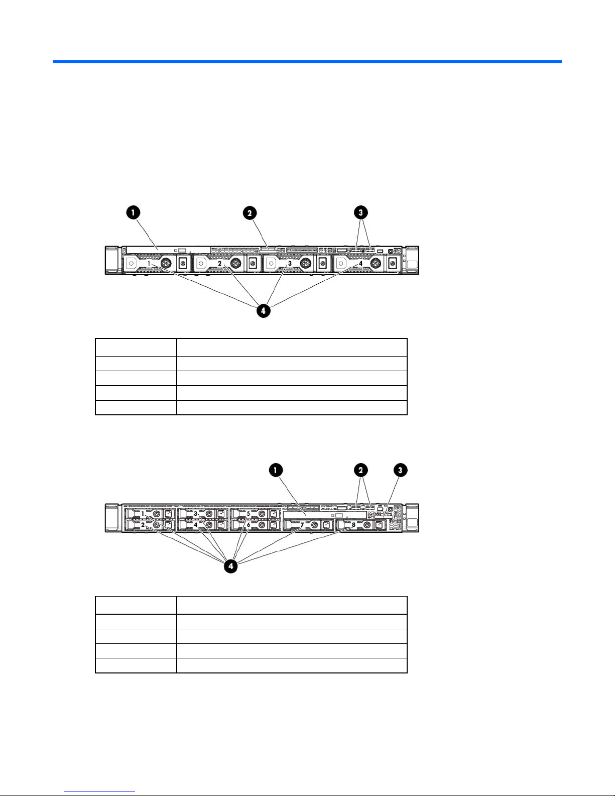
Front panel components
• Four-bay LFF drive model
Item Description
1
2
3
4
Optical drive
Serial label pull tab
USB connectors
LFF drives
• Eight-bay SFF drive model
Item Description
1
2
3
4
Optical drive
USB connectors
Serial label pull tab
SFF drives
Component identification 7
Page 8
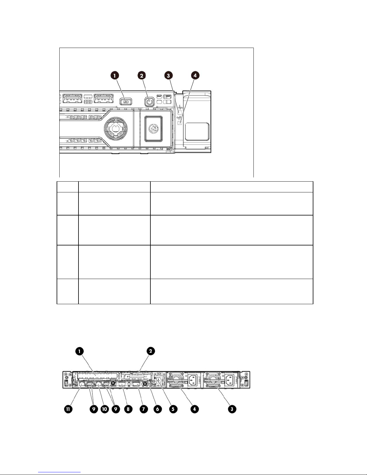
Front panel LEDs and buttons
Item Description Status
1
2
3
4
UID LED/button Blue = Identification is activated.
Flashing blue = System is being managed remotely.
Off = Identification is deactivated.
Power On/Standby button
and system power LED
Health LED Green = System is on and system health is normal.
NIC status LED Green = Linked to network
Green = System is on.
Flashing green = Waiting for power.
Amber = System is in standby, but power is still applied.
Off = Power cord is not attached or power supply failed.
Flashing amber = System health is degraded.
Flashing red = System health is critical.
Off = System is off.
Flashing green = Network activity
Off = No network link
Rear panel components
Component identification 8
Page 9
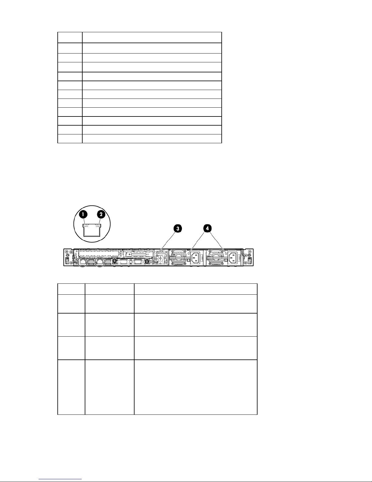
Slot 1 PCIe x8 (4, 1)*
NIC connector 2
•
•
•
•
Item Description
1
2
3
4
5
6
7
8
9
10
11
Slot 2 PCIe x16 (16, 8, 4, 1)*
Power supply 1
Power supply 2
Dedicated iLO management port (optional)
UID LED button
Serial connector
Video connector
USB connectors
NIC 1/shared iLO management connector
* For more information on the riser board slots supported by the onboard PCI riser connectors, see "PCIe riser
board slot definitions (on page 11)."
Rear panel LEDs and buttons
Item Description Status
1
2
3
4
NIC link LED Green = Link exists
NIC status LED Green = Activity exists
UID LED/button Blue = Identification is activated
Power supply LED
(for hot-plug HP CS
power supplies
only)
Off = No link exists
Flashing green = Activity exists
Off = No activity exists
Flashing blue = System is being managed remotely
Off = Identification is deactivated
Green = Normal
Off = One or more of the following conditions
exists:
Power is unavailable
Power supply failed
Power supply is in standby mode
Power supply error
Component identification 9
Page 10
System board components
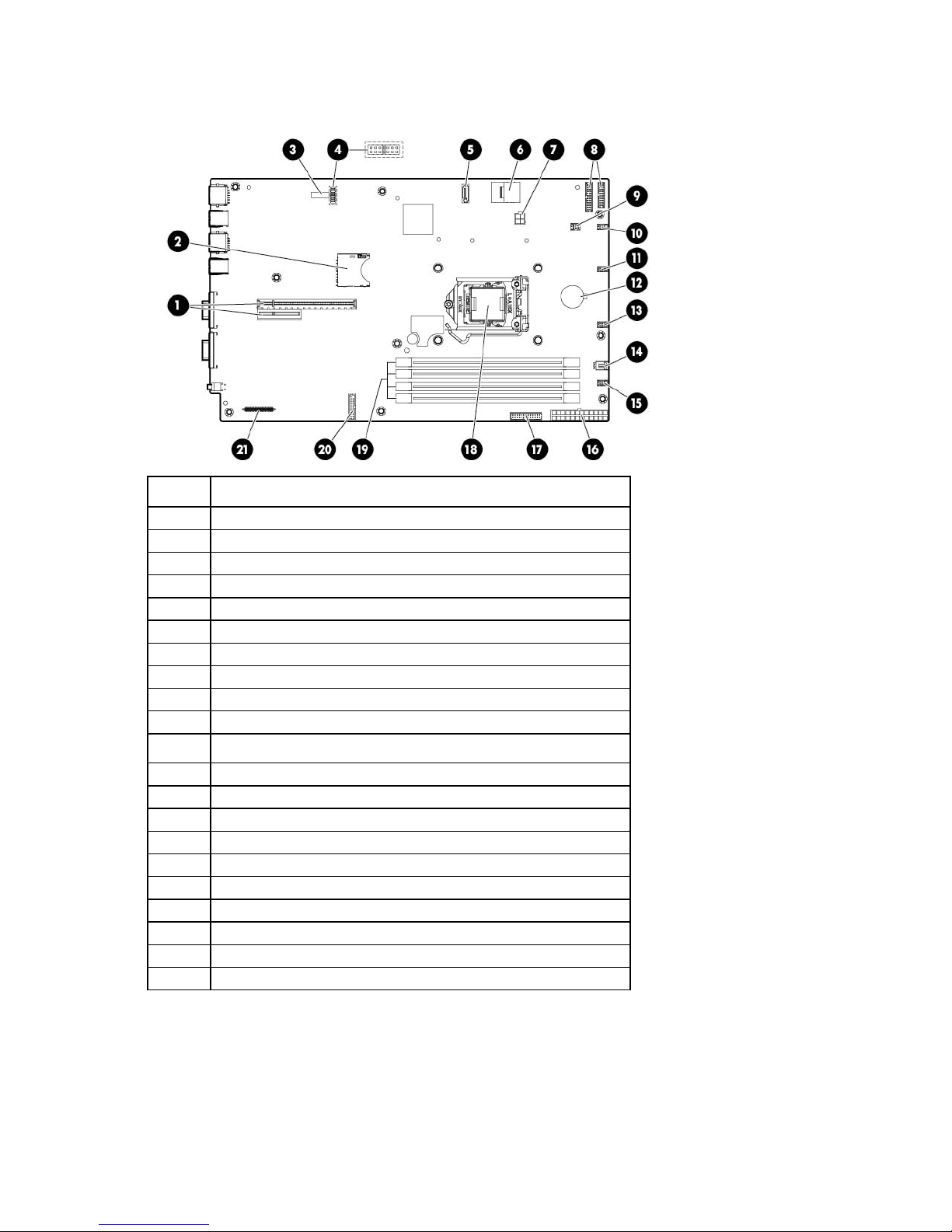
4-pin power supply connector
Fan connector 1
Item Description
1
2
3
4
5
6
7
8
9
10
11
12
13
14
15
16
17
18
19
20
21
PCI riser connectors*
SD card slot
System maintenance switch
NMI header
SATA connector
Mini-SAS connector
Front panel connectors
Internal USB connector
Fan connector 4
Fan connector 3
System battery
Fan connector 2
Discovery service connector
24-pin power supply connector
26-pin RPS connector
Processor socket
DIMM slots
TPM connector
Dedicated iLO module connector
* For more information on the riser board slots supported by the onboard PCI riser connectors, see "PCIe riser
board slot definitions (on page 11)."
Component identification 10
Page 11

DIMM slot locations
Off
Off = Power-on password is enabled
DIMM slots are numbered sequentially (1 through 4) for the processor. The supported AMP modes use the
letter assignments for population guidelines
PCIe riser board slot definitions
The transfer rate of the PCIe riser board slot 2 depends on the processor model installed. The slot can either
run in PCIe2 (5 GT/s) or PCIe3 (8 GT/s) rate.
• Intel Xeon Processor E3-xxxx Series, Intel Core i3 Processor Series, Intel Pentium G2120, G2100T, and
G630.
Slot number Type Length Height Connector link width Negotiable link width
1
2
• Intel Xeon Processor E3-xxxxV2 Series
Slot number Type Length Height Connector link width Negotiable link width
1
2
PCIe2 Half Half x8 x4
PCIe2 Half Full x16 x16
PCIe2 Half Half x8 x4
PCIe3 Half Full x16 x16
System maintenance switch
Switch Default Function
1
2
5
Off Off = No function
On = iLO security is disabled
Off Off = System configuration can be
changed
On = System configuration is locked
On = Power-on password is disabled
Component identification 11
Page 12
Switch Default Function
6
3, 4, 7, 8, 9,
10, 11, 12
When the system maintenance switch position 6 is set to the On position, the system is prepared to erase all
system configuration settings from both CMOS and NVRAM.
CAUTION: Clearing CMOS and/or NVRAM deletes configuration information. Be sure to
properly configure the server or data loss could occur.
NMI header
The NMI header enables administrators to perform a memory dump before performing a hard reset. Crash
dump analysis is an essential part of eliminating potential reliability issues, such as hangs or crashes in
operating systems, device drivers, and applications. Many crashes can freeze a system, requiring you to
perform a hard reset. Resetting the system erases any information that supports root cause analysis.
Systems running Microsoft® Windows® experience a blue-screen trap when the OS crashes. When this
happens, Microsoft® recommends that system administrators perform an NMI event by temporarily shorting
the NMI header with a jumper. The NMI event enables a hung system to become responsive again.
Off Off = No function
On = ROM reads configuration as
invalid
— Reserved
For additional information, see the HP website
(http://h20000.www2.hp.com/bc/docs/support/SupportManual/c00797875/c00797875.pdf).
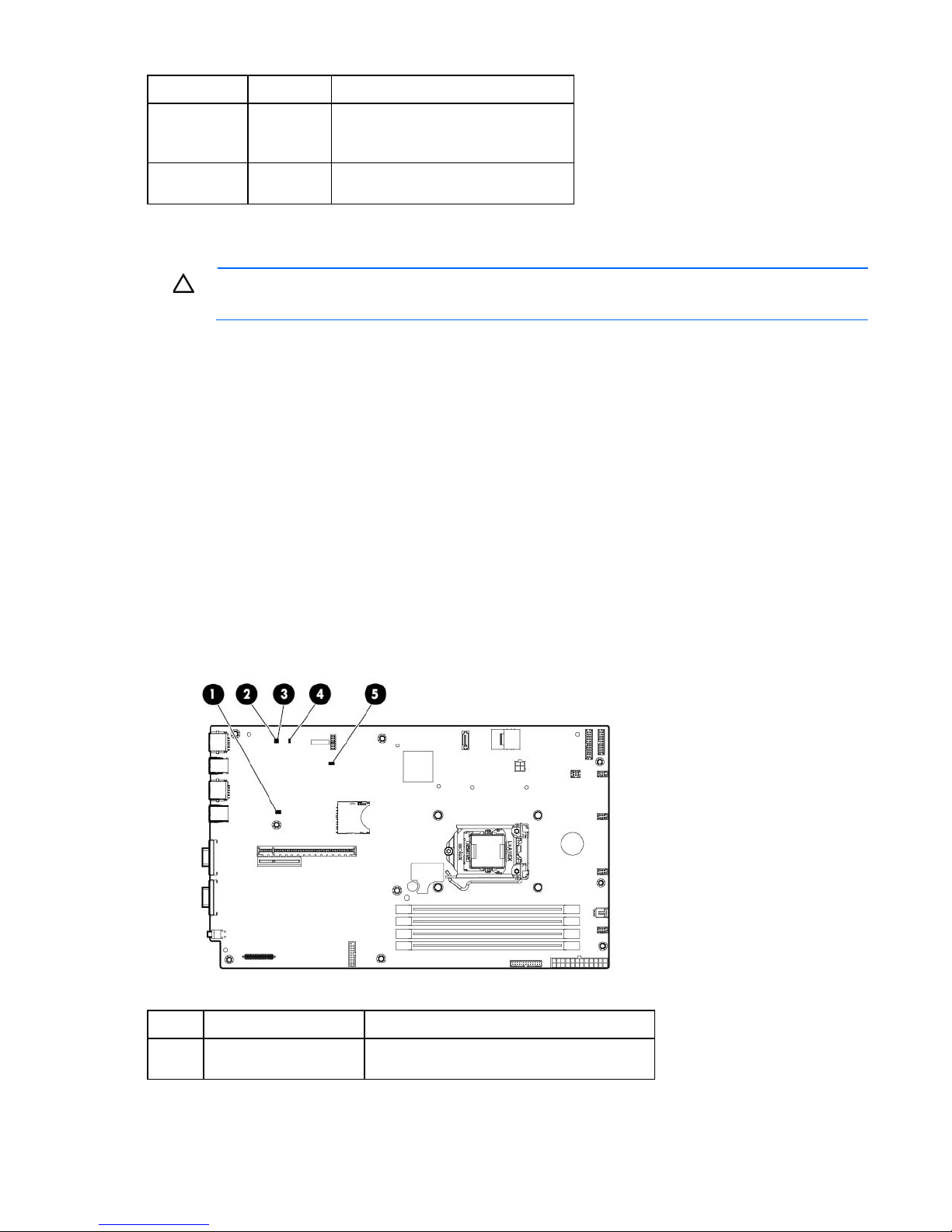
System board LED definitions
Item Description Status
1
Initialization failure Yellow = System initialization failure
Off = Normal
Component identification 12
Page 13
Item Description Status
2
3
4
5
Power supply 1 failure Red = Power supply failure
Power supply 2 failure Red = Power supply failure
Auxiliary power Green = Standby power indicator
Processor error Yellow = Critical processor error
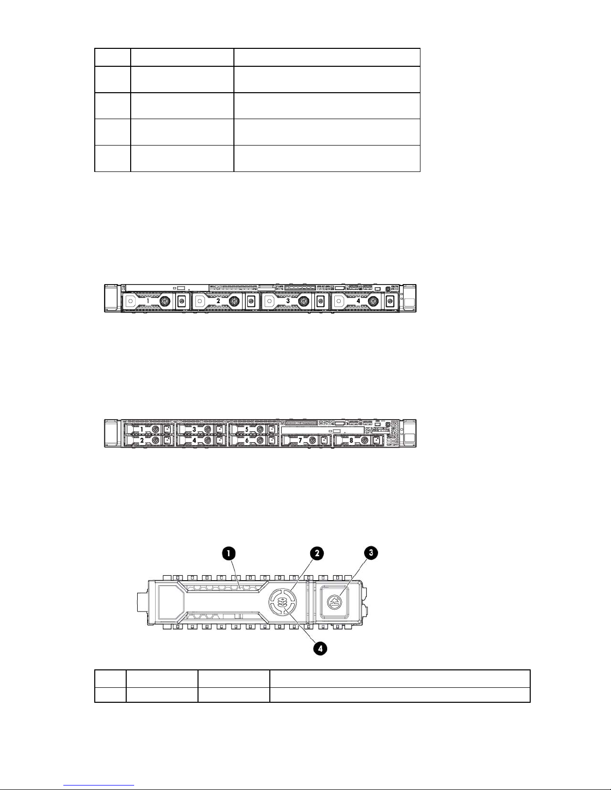
Drive numbering
• Four-bay LFF drive model
Off = Normal
Off = Normal
Off = Standby power invalid
Off = Normal
• Eight-bay SFF drive model
Drive LED definitions
Item LED Status Definition
1
Locate Solid blue The drive is being identified by a host application.
Component identification 13
Page 14
Item LED Status Definition
2
Activity ring Rotating green Drive activity
3
Do not remove Solid white Do not remove the drive. Removing the drive causes one or more of
4
Drive status Solid green The drive is a member of one or more logical drives.
Flashing blue The drive carrier firmware is being updated or requires an update.
Off No drive activity
the logical drives to fail.
Off Removing the drive does not cause a logical drive to fail.
Flashing green The drive is rebuilding or performing a RAID migration, stripe size
migration, capacity expansion, or logical drive extension, or is
erasing.
Flashing
amber/green
Flashing amber The drive is not configured and predicts the drive will fail.
Solid amber The drive has failed.
Off The drive is not configured by a RAID controller.
The drive is a member of one or more logical drives and predicts
the drive will fail.
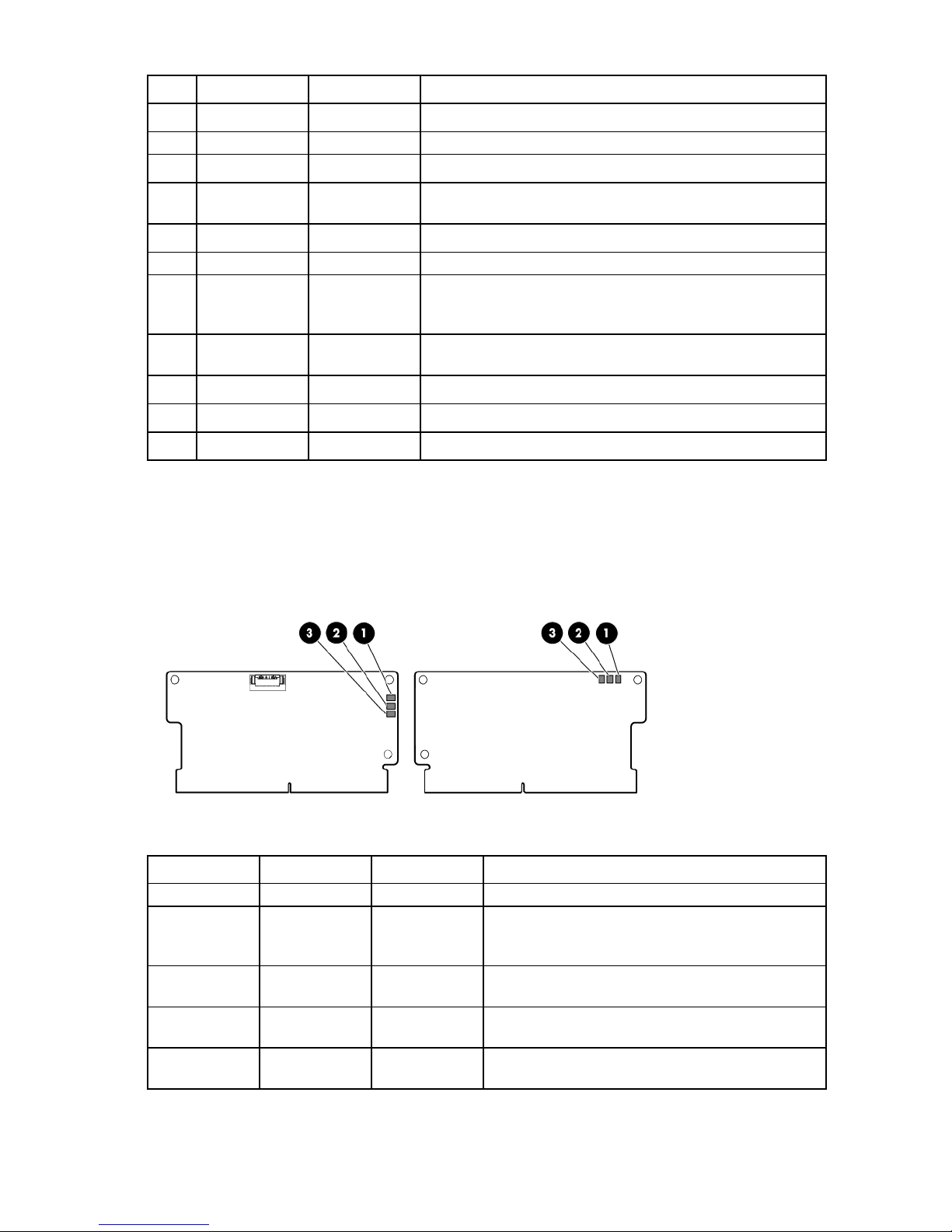
FBWC module LED definitions
The FBWC module has three single-color LEDs (one amber and two green). The LEDs are duplicated on the
reverse side of the cache module to facilitate status viewing.
1 - Amber 2 - Green 3 - Green Interpretation
Off
Off
Off
Off
Off
Off Off The cache module is not powered.
Flashing 0.5 Hz Flashing 0.5 Hz The cache microcontroller is executing from within its
boot loader and receiving new flash code from the host
controller.
Flashing 1 Hz Flashing 1 Hz The cache module is powering up, and the capacitor
pack is charging.
Off Flashing 1 Hz The cache module is idle, and the capacitor pack is
charging.
Off On The cache module is idle, and the capacitor pack is
charged.
Component identification 14
Page 15
1 - Amber 2 - Green 3 - Green Interpretation
Off
Off
Off
Flashing 1 Hz
Flashing 1 Hz
Flashing 1 Hz
Flashing 2 Hz
Flashing 2 Hz
On
On
On On The cache module is idle, the capacitor pack is charged,
and the cache contains data that has not yet been
written to the drives.
Flashing 1 Hz Off A backup is in progress.
On Off The current backup is complete with no errors.
Flashing 1 Hz Off The current backup failed, and data has been lost.
Flashing 1 Hz On A power error occurred during the previous or current
boot. Data may be corrupt.
On Off An overtemperature condition exists.
Flashing 2 Hz Off The capacitor pack is not attached.
Flashing 2 Hz On The capacitor has been charging for 10 minutes, but
has not reached sufficient charge to perform a full
backup.
On Off The current backup is complete, but power fluctuations
occurred during the backup.
On On The cache module microcontroller has failed.
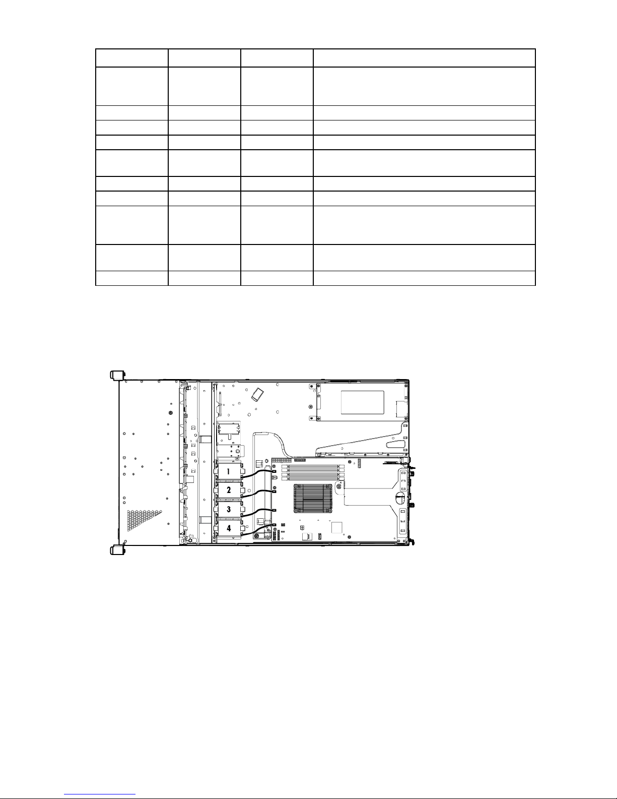
Fan locations
Component identification 15
Page 16
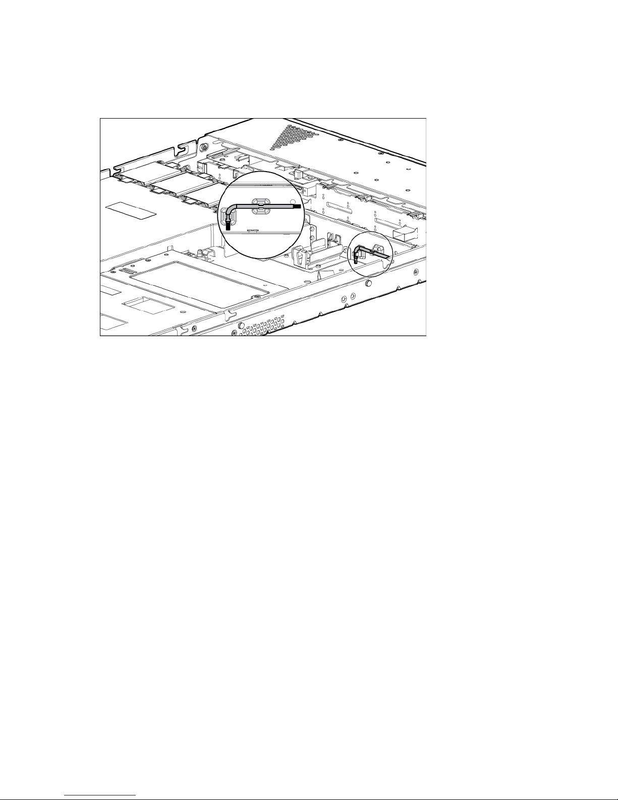
T-10/T-15 Torx screwdriver
The server includes a T-10/T-15 Torx screwdriver located beside the capacitor pack holder. Use the
screwdriver to loosen screws during hardware configuration procedures.
Component identification 16
Page 17

Operations
Power up the server
1. Connect each power cord to the server.
2. Connect each power cord to the power source.
3. Press the Power On/Standby button.
The server exits standby mode and applies full power to the system. The system power LED changes
Power down the server
from amber to green.
Before powering down the server for any upgrade or maintenance procedures, perform a backup of critical
server data and programs.
WARNING: To reduce the risk of personal injury, electric shock, or damage to the equipment,
remove the power cord to remove power from the server. The front panel Power On/Standby
button does not completely shut off system power. Portions of the power supply and some internal
circuitry remain active until AC power is removed.
IMPORTANT: When the server is in standby mode, auxiliary power is still being provided to the
system.
To power down the server, use one of the following methods:
• Press and release the Power On/Standby button.
This method initiates a controlled shutdown of applications and the OS before the server enters standby
mode.
• Press and hold the Power On/Standby button for more than 4 seconds to force the server to enter
standby mode.
This method forces the server to enter standby mode without properly exiting applications and the OS.
If an application stops responding, you can use this method to force a shutdown.
• Use a virtual power button selection through iLO.
This method initiates a controlled remote shutdown of applications and the OS before the server enters
standby mode.
Before proceeding, verify the server is in standby mode by observing that the system power LED is amber.
Extend the server from the rack
Operations 17
Page 18

IMPORTANT: The requirement of extending or removing the server from the rack when
for all rack server installations. A third person may be required to help align the server if the
performing installation and maintenance procedures depends on the rail system used:
• If using a ball-bearing rail system, you can perform most installations and maintenance by
simply extending the server from the rack.
• If using a friction rail system, to perform installations or maintenance that requires access panel
removal, remove the server from the rack.
To extend the server from an HP, Compaq-branded, Telco, or third-party rack:
1. Power down the server (on page 17).
2. Remove all power:
a. Disconnect each power cord from the power source.
b. Disconnect each power cord from the server.
3. Disconnect all peripheral cables.
WARNING: To reduce the risk of personal injury or equipment damage, be sure that the rack is
adequately stabilized before extending a component from the rack.
WARNING: To reduce the risk of personal injury, be careful when pressing the server rail-release
latches and sliding the server into the rack. The sliding rails could pinch your fingers.
4. Pull down the quick release levers on each side of the server.
5. Extend the server on the rack rails until the server rail-release latches engage.
If the server does not extend from the rack, use a T-25 Torx screwdriver to loosen the screws located
within the lever housing.
6. After performing the installation or maintenance procedure, slide the server into the rack. For more
information, see the documentation that ships with the rack-mounting option.
7. Connect the peripheral cables.
8. Connect each power cord to the server.
9. Connect each power cord to the power source.
Remove the server from the rack
WARNING: This server is very heavy. To reduce the risk of personal injury or damage to the
equipment:
• Observe local occupational health and safety requirements and guidelines for manual
material handling.
• Get help to lift and stabilize the product during installation or removal, especially when the
product is not fastened to the rails. HP recommends that a minimum of two people are required
server is installed higher than chest level.
• Use caution when installing the server in or removing the server from the rack; it is unstable
when not fastened to the rails.
Operations 18
Page 19
IMPORTANT: The requirement of extending or removing the server from the rack when
performing installation and maintenance procedures depends on the rail system used:
• If using a ball-bearing rail system, you can perform most installations and maintenance by
simply extending the server from the rack.
• If using a friction rail system, to perform installations or maintenance that requires access panel
removal, remove the server from the rack.
To remove the server from an HP, Compaq-branded, Telco, or third-party rack:
1. Power down the server (on page 17).
2. Disconnect all peripheral cables and power cords from the server rear panel.
3. Extend the server from the rack (on page 17).
4. Remove the server from the rack. For more information, see the documentation that ships with the rack
mounting option.
5. Place the server on a sturdy, level surface.
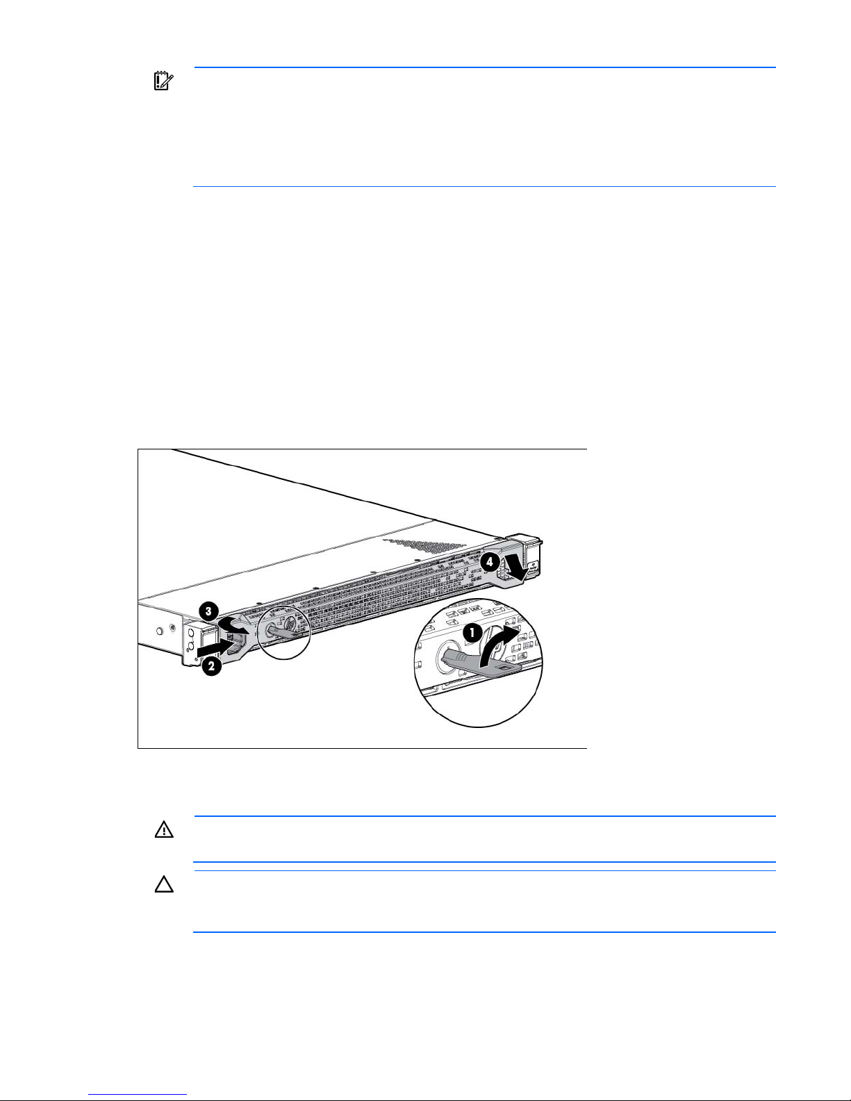
Remove the security bezel (optional)
To access the front panel components, unlock and then remove the security bezel.
Remove the access panel
WARNING: To reduce the risk of personal injury from hot surfaces, allow the drives and the
1. Power down the server (on page 17).
2. Remove all power:
internal system components to cool before touching them.
CAUTION: Do not operate the server for long periods with the access panel open or removed.
Operating the server in this manner results in improper airflow and improper cooling that can
lead to thermal damage.
Operations 19
Page 20

a.
Disconnect each power cord from the power source.
b. Disconnect each power cord from the server.
3. Do one of the following:
o Extend the server from the rack (on page 17).
o Remove the server from the rack (on page 18).
4. Open the locking latch, slide the access panel to the rear of the chassis, and then remove the access
panel.
If the latch is locked, use a T-15 Torx screwdriver to unlock the latch.
Install the access panel
1. Place the access panel on top of the server with the locking latch open. Allow the panel to extend past
the rear of the server by approximately 1.25 cm (0.5 inch).
2. Press the locking latch. The access panel slides to a closed position.
3. Use a T-15 Torx screwdriver to tighten the security screw on the locking latch.
Remove the air baffle
CAUTION: For proper cooling, do not operate the server without the access panel, baffles,
expansion slot covers, or blanks installed. If the server supports hot-plug components, minimize
To remove the component:
1. Power down the server (on page 17).
2. Remove all power:
the amount of time the access panel is open.
a. Disconnect each power cord from the power source.
b. Disconnect each power cord from the server.
3. Do one of the following:
o Extend the server from the rack (on page 17).
o Remove the server from the rack (on page 18).
4. Remove the access panel (on page 19).
Operations 20
Page 21
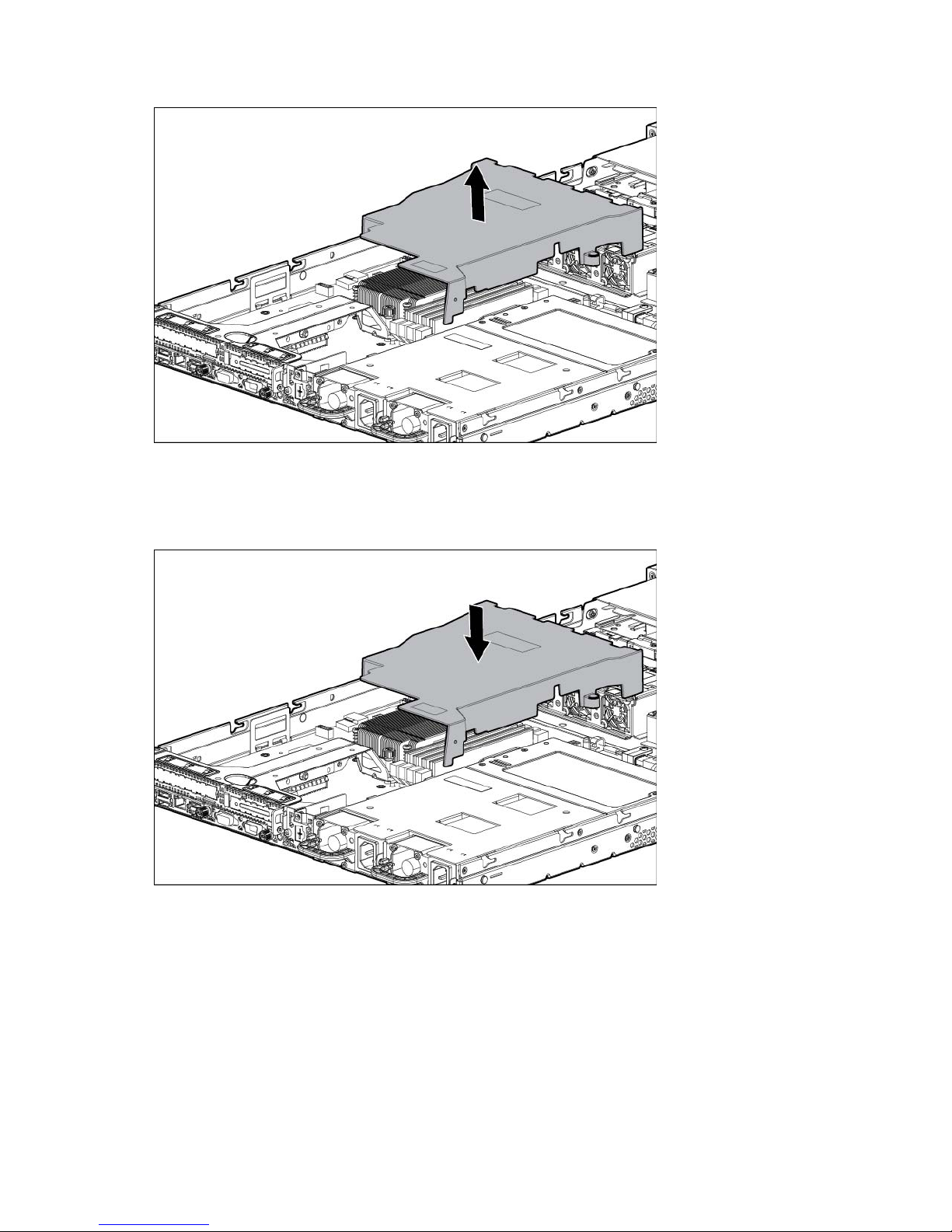
5.
Remove the air baffle.
Install the air baffle
1. Place the air baffle on top of the server.
2. Install the access panel (on page 20).
3. Do one of the following:
o Slide the server into the rack.
o Install the server into the rack ("Installing the server into the rack" on page 28).
4. Power up the server (on page 17).
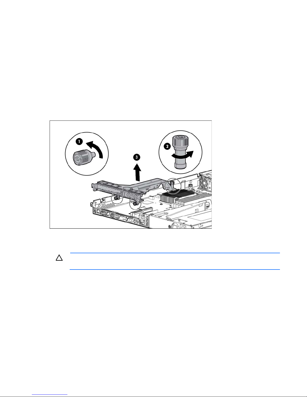
Remove the PCI riser cage
To remove the component:
Operations 21
Page 22
1.
Power down the server (on page 17).
2. Remove all power:
a. Disconnect each power cord from the power source.
b. Disconnect each power cord from the server.
3. Do one of the following:
o Extend the server from the rack (on page 17).
o Remove the server from the rack (on page 18).
4. Remove the access panel (on page 19).
5. Disconnect all cables connected to existing expansion boards.
6. Loosen the PCI riser cage thumbscrews.
7. Lift the PCI riser cage to unseat the PCI riser boards.
Install the PCI riser cage
CAUTION: To prevent damage to the server or expansion boards, power down the server, and
1. Align the PCI riser cage with the guide pin located on the chassis, and then press down the PCI riser
disconnect all power cords before removing or installing the PCI riser cage.
cage.
Operations 22
Page 23
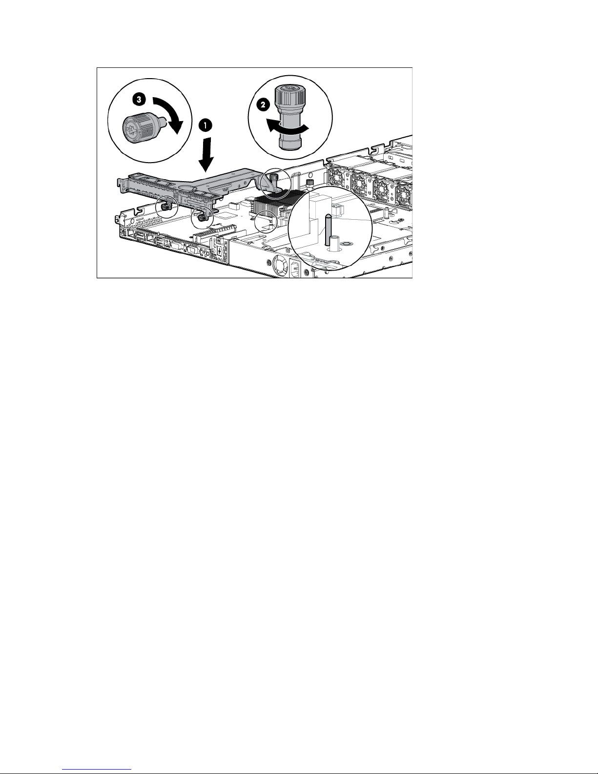
2.
Tighten the PCI riser cage thumbscrews.
3. Install the access panel (on page 20).
4. Do one of the following:
o Slide the server into the rack.
o Install the server into the rack ("Installing the server into the rack" on page 28).
5. Power up the server (on page 17).
Operations 23
Page 24

Setup
Optional installation services
Delivered by experienced, certified engineers, HP Care Pack services help you keep your servers up and
running with support packages tailored specifically for HP ProLiant systems. HP Care Packs let you integrate
both hardware and software support into a single package. A number of service level options are available
to meet your needs.
HP Care Pack Services offer upgraded service levels to expand your standard product warranty with
easy-to-buy, easy-to-use support packages that help you make the most of your server investments. Some of
the Care Pack services are:
• Hardware support
o 6-Hour Call-to-Repair
o 4-Hour 24x7 Same Day
o 4-Hour Same Business Day
• Software support
o Microsoft® operating systems
o Linux operating systems
o HP ProLiant Essentials (HP SIM and RDP)
• Integrated hardware and software support
o Critical Service
o Proactive 24
o Support Plus
o Support Plus 24
• Startup and implementation services for both hardware and software
For more information on HP Care Pack Services, see the HP website
(http://www.hp.com/services/carepack).
Rack planning resources
The rack resource kit ships with all HP branded or Compaq branded 9000, 10000, and H9 series racks. For
more information on the content of each resource, see the rack resource kit documentation.
Optimum environment
When installing the server in a rack, select a location that meets the environmental standards described in
this section.
Setup 24
Page 25

Space and airflow requirements
ensures proper airflow. Using a rack without blanking panels results in improper cooling that can
party rack is used, observe the following additional requirements to ensure
To allow for servicing and adequate airflow, observe the following space and airflow requirements when
deciding where to install a rack:
• Leave a minimum clearance of 63.5 cm (25 inches) in front of the rack.
• Leave a minimum clearance of 76.2 cm (30 inches) behind the rack.
• Leave a minimum clearance of 121.9 cm (48 inches) from the back of the rack to the back of another
rack or row of racks.
HP servers draw in cool air through the front and expel warm air through the rear. Therefore, the front and
rear rack doors must be adequately ventilated to allow ambient room air to enter the cabinet, and the rear
door must be adequately ventilated to allow the warm air to escape from the cabinet.
CAUTION: To prevent improper cooling and damage to the equipment, do not block the
When vertical space in the rack is not filled by a server or rack component, the gaps between the
components might cause changes in airflow through the rack and across the servers. To maintain airflow
cover all gaps with blanking panels.
ventilation openings.
CAUTION: Always use blanking panels to fill empty vertical spaces in the rack. This arrangement
lead to thermal damage.
The 9000 and 10000 series racks provide proper server cooling from flow-through perforations in the front
and rear doors that provide 64% open area for ventilation.
CAUTION: When using a Compaq branded 7000 series rack, install the high airflow rack door
insert (PN 327281-B21 for 42U rack, PN 157847-B21 for 22U rack) to provide proper
front-to-back airflow and cooling.
CAUTION: If a third-
adequate airflow and to prevent damage to the equipment:
• Front and rear doors—If the 42U rack includes closing front and rear doors, you must allow
5,350 sq cm (830 sq in) of holes evenly distributed from top to bottom to permit adequate
airflow (equivalent to the required 64 percent open area for ventilation).
• Side—The clearance between the installed rack component and the side panels of the rack
must be a minimum of 7 cm (2.75 in).
Temperature requirements
To ensure continued safe and reliable equipment operation, install or position the system in a well-ventilated,
climate-controlled environment.
The maximum recommended ambient operating temperature (TMRA) for most server products is 35°C
(95°F). The temperature in the room where the rack is located must not exceed 35°C (95°F).
CAUTION: To reduce the risk of damage to the equipment when installing third-party options:
• Do not permit optional equipment to impede airflow around the server or to increase the
internal rack temperature beyond the maximum allowable limits.
• Do not exceed the manufacturer’s TMRA.
Setup 25
Page 26

Power requirements
Installation of this equipment must comply with local and regional electrical regulations governing the
installation of information technology equipment by licensed electricians. This equipment is designed to
operate in installations covered by NFPA 70, 1999 Edition (National Electric Code) and NFPA-75, 1992
(code for Protection of Electronic Computer/Data Processing Equipment). For electrical power ratings on
options, refer to the product rating label or the user documentation supplied with that option.
WARNING: To reduce the risk of personal injury, fire, or damage to the equipment, do not
overload the AC supply branch circuit that provides power to the rack. Consult the electrical
When installing more than one server, you may need to use additional power distribution devices to safely
provide power to all devices. Observe the following guidelines:
• Balance the server power load between available AC supply branch circuits.
• Do not allow the overall system AC current load to exceed 80 percent of the branch circuit AC current
authority having jurisdiction over wiring and installation requirements of your facility.
CAUTION: Protect the server from power fluctuations and temporary interruptions with a
regulating uninterruptible power supply. This device protects the hardware from damage caused
by power surges and voltage spikes and keeps the system in operation during a power failure.
rating.
• Do not use common power outlet strips for this equipment.
• Provide a separate electrical circuit for the server.
Electrical grounding requirements
The server must be grounded properly for proper operation and safety. In the United States, you must install
the equipment in accordance with NFPA 70, 1999 Edition (National Electric Code), Article 250, as well as
any local and regional building codes. In Canada, you must install the equipment in accordance with
Canadian Standards Association, CSA C22.1, Canadian Electrical Code. In all other countries, you must
install the equipment in accordance with any regional or national electrical wiring codes, such as the
International Electrotechnical Commission (IEC) Code 364, parts 1 through 7. Furthermore, you must be sure
that all power distribution devices used in the installation, such as branch wiring and receptacles, are listed
or certified grounding-type devices.
Because of the high ground-leakage currents associated with multiple servers connected to the same power
source, HP recommends the use of a PDU that is either permanently wired to the building’s branch circuit or
includes a nondetachable cord that is wired to an industrial-style plug. NEMA locking-style plugs or those
complying with IEC 60309 are considered suitable for this purpose. Using common power outlet strips for
the server is not recommended.
Server warnings and cautions
Setup 26
Page 27

for all rack server installations. A third person may be required to help align the server if the
WARNING: This server is very heavy. To reduce the risk of personal injury or damage to the
equipment:
• Observe local occupational health and safety requirements and guidelines for manual
material handling.
• Get help to lift and stabilize the product during installation or removal, especially when the
product is not fastened to the rails. HP recommends that a minimum of two people are required
server is installed higher than chest level.
• Use caution when installing the server in or removing the server from the rack; it is unstable
when not fastened to the rails.
WARNING: To reduce the risk of personal injury from hot surfaces, allow the drives and the
internal system components to cool before touching them.
WARNING: To reduce the risk of personal injury, electric shock, or damage to the equipment,
remove the power cord to remove power from the server. The front panel Power On/Standby
button does not completely shut off system power. Portions of the power supply and some internal
circuitry remain active until AC power is removed.
CAUTION: Protect the server from power fluctuations and temporary interruptions with a
regulating uninterruptible power supply. This device protects the hardware from damage caused
by power surges and voltage spikes and keeps the system in operation during a power failure.
CAUTION: Do not operate the server for long periods with the access panel open or removed.
Operating the server in this manner results in improper airflow and improper cooling that can
lead to thermal damage.
Rack warnings
WARNING: To reduce the risk of personal injury or damage to the equipment, be sure that:
• The leveling jacks are extended to the floor.
• The full weight of the rack rests on the leveling jacks.
• The stabilizing feet are attached to the rack if it is a single-rack installation.
• The racks are coupled together in multiple-rack installations.
• Only one component is extended at a time. A rack may become unstable if more than one
component is extended for any reason.
WARNING: To reduce the risk of personal injury or equipment damage when unloading a rack:
• At least two people are needed to safely unload the rack from the pallet. An empty 42U rack
can weigh as much as 115 kg (253 lb), can stand more than 2.1 m (7 ft) tall, and might
become unstable when being moved on its casters.
• Never stand in front of the rack when it is rolling down the ramp from the pallet. Always handle
the rack from both sides.
WARNING: To reduce the risk of personal injury or damage to the equipment, adequately
stabilize the rack before extending a component outside the rack. Extend only one component at
a time. A rack may become unstable if more than one component is extended.
Setup 27
Page 28

WARNING: When installing a server in a telco rack, be sure that the rack frame is adequately
secured at the top and bottom to the building structure.
Identifying the contents of the server shipping carton
Unpack the server shipping carton and locate the materials and documentation necessary for installing the
server. All the rack mounting hardware necessary for installing the server into the rack is included with the
rack or the server.
The contents of the server shipping carton include:
• Server
• Power cord
• Printed setup documentation, Documentation CD, and software products
• Rack mounting hardware kit and documentation (optional)
You need the following items for some procedures:
• T-25 Torx screwdriver (to use on the screws located inside the server quick-release levers)
• T-10/T-15 Torx screwdriver (on page 16)
• Flathead screwdriver (for dedicated iLO module installation)
• Hardware options
• Operating system or application software
Installing hardware options
Install any hardware options before initializing the server. For options installation information, see the option
documentation. For server-specific information, see "Hardware options installation (on page 32)."
Installing the server into the rack
To install the server into a rack with square, round, or threaded holes, refer to the instructions that ship with
the rack hardware kit.
If you are installing the server into a telco rack, order the appropriate option kit at the RackSolutions website
(http://www.racksolutions.com/hp). Follow the server-specific instructions on the website to install the rack
brackets.
Use the following information when connecting peripheral cables and power cords to the server.
Setup 28
Page 29
WARNING: This server is very heavy. To reduce the risk of personal injury or damage to the
equipment:
• Observe local occupational health and safety requirements and guidelines for manual
material handling.
• Get help to lift and stabilize the product during installation or removal, especially when the
product is not fastened to the rails. HP recommends that a minimum of two people are required
for all rack server installations. A third person may be required to help align the server if the
server is installed higher than chest level.
• Use caution when installing the server in or removing the server from the rack; it is unstable
when not fastened to the rails.
CAUTION: Always plan the rack installation so that the heaviest item is on the bottom of the rack.
Install the heaviest item first, and continue to populate the rack from the bottom to the top.
To install the server in an HP, Compaq-branded, Telco, or third party rack:
1. Install the server and cable management arm option into the rack. See the documentation that ships with
the Quick Deploy Rail System.
2. Connect peripheral devices to the server. For information on identifying connectors, see "Rear panel
components (on page 8)."
WARNING: To reduce the risk of electric shock, fire, or damage to the equipment, do not plug
telephone or telecommunications connectors into RJ-45 connectors.
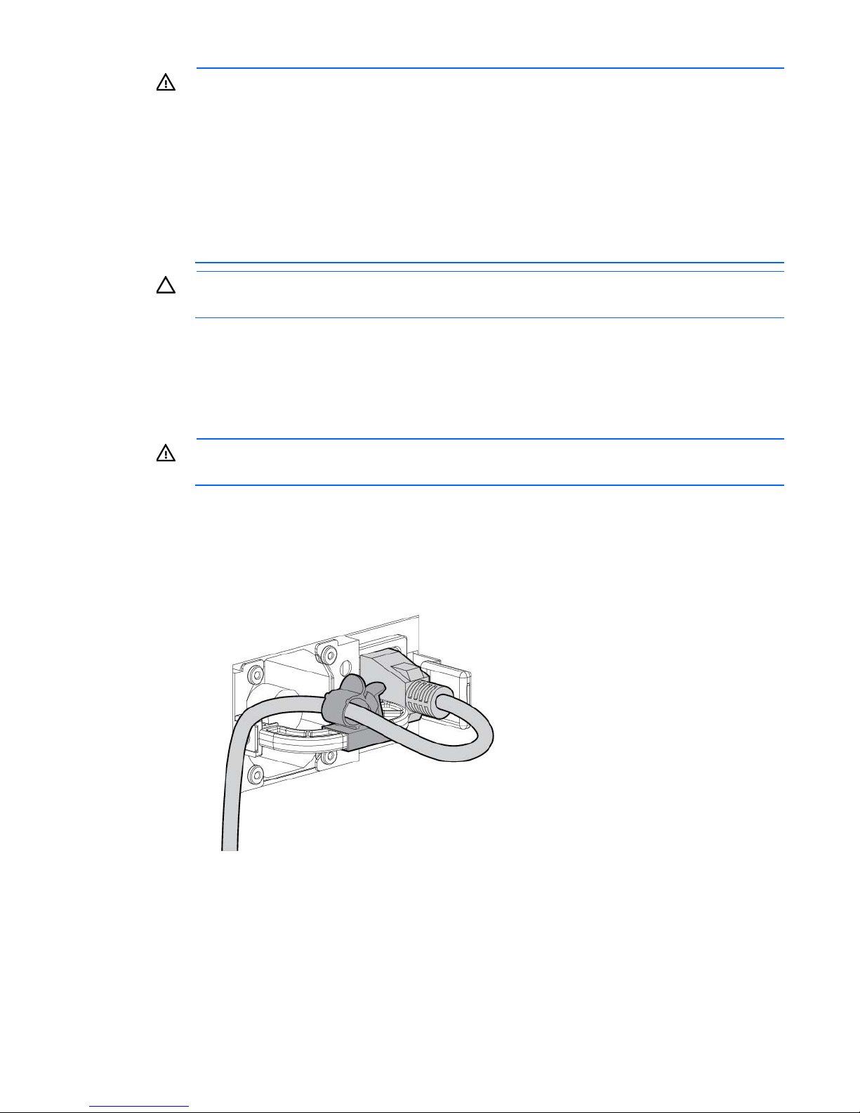
3. Connect the power cord to the rear of the server.
4. When using a hot-plug HP CS power supply, use the strain relief clip from the server hardware kit to
secure the power cord.
5. Connect the power cord to the power source.
Setup 29
Page 30

WARNING: To reduce the risk of electric shock or damage to the equipment:
• Do not disable the power cord grounding plug. The grounding plug is an important safety
feature.
• Plug the power cord into a grounded (earthed) electrical outlet that is easily accessible at all
times.
• Unplug the power cord from the power supply to disconnect power to the equipment.
• Do not route the power cord where it can be walked on or pinched by items placed against it.
Pay particular attention to the plug, electrical outlet, and the point where the cord extends from
the server.
Installing the operating system
This ProLiant server does not ship with provisioning media. Everything needed to manage and install the
system software and firmware is preloaded on the server.
To operate properly, the server must have a supported operating system. For the latest information on
operating system support, see the HP website (http://www.hp.com/go/supportos).
To install an operating system on the server, use one of the following methods:
• Intelligent Provisioning—The iLO Management Engine is a new feature on ProLiant servers that contains
Intelligent Provisioning for embedded deployment, updating, and provisioning capabilities. Intelligent
Provisioning can configure the server and install an operating system, eliminating the need for
SmartStart CDs and Smart Update Firmware DVDs.
To install an operating system on the server with Intelligent Provisioning (local or remote):
a. Connect the Ethernet cable, and then power on the server.
b. During server POST, press the F10 key.
c. Complete the initial Preferences and Registration portion of Intelligent Provisioning (on page 64).
d. At the 1 Start screen, click the Configure and Install button.
e. To finish the installation, follow the onscreen prompts. An Internet connection is required to update
the firmware and systems software.
• Remote deployment installation—To remotely deploy an operating system, use Insight Control server
deployment for an automated solution.
For additional system software and firmware updates, download the HP Service Pack for ProLiant from the HP
website (http://www.hp.com/go/spp/download). Software and firmware must be updated before using
the server for the first time, unless any installed software or components require an older version. For more
information, see "Keeping the system current (on page 72)."
The Smart Update Firmware DVD ISO is also available at the download tab on the HP website
(http://www.hp.com/go/foundation).
For more information on using these installation methods, see the HP website (http://www.hp.com/go/ilo).
Powering on and selecting boot options
1. Connect the Ethernet cable and press the Power On/Standby button.
2. During the initial boot:
Setup 30
Page 31

o
To modify the server configuration ROM default settings, press F9 when prompted from the start up
sequence to enter the RBSU. By default, RBSU runs in the English language.
o If you do not need to modify the server configuration and are ready to install the system software,
press F10 to access Intelligent Provisioning.
NOTE: If an HP Smart Array controller has been added or is embedded in the system, the
controller defaults to a RAID configuration based on the size and number of hard drives installed.
For more information on modifying the controller default settings, see the documentation on the
Documentation CD.
For more information on automatic configuration, see the HP ROM-Based Setup Utility User Guide on the
Documentation CD or the iLO Management Engine Information Library
(http://www.hp.com/go/ilomgmtengine/docs).
Registering the server
To register the server, refer to the HP Registration website (http://register.hp.com).
Setup 31
Page 32
Hardware options installation
Introduction
If more than one option is being installed, read the installation instructions for all the hardware options and
identify similar steps to streamline the installation process.
WARNING: To reduce the risk of personal injury from hot surfaces, allow the drives and the
Security bezel option
internal system components to cool before touching them.
CAUTION: To prevent damage to electrical components, properly ground the server before
beginning any installation procedure. Improper grounding can cause electrostatic discharge.
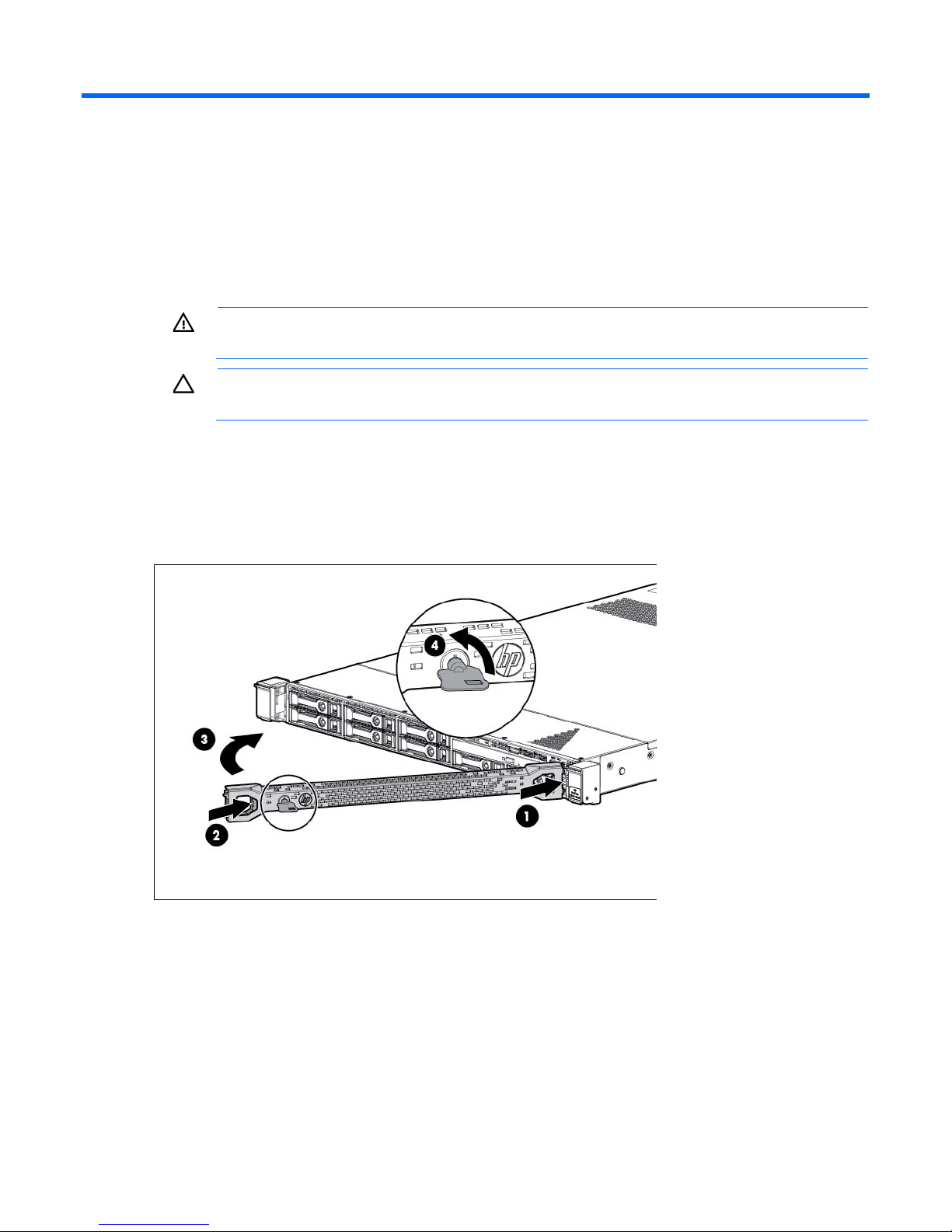
The security bezel helps prevent unauthorized physical access to the front panel components.
Install the security bezel and then lock it with the key provided with the kit.
Drive options
The server supports up to four non-hot-plug or hot-plug LFF drives and up to eight hot-plug SFF drives.
The embedded storage controller supports SATA drive installation only. For SAS drive installation, install the
storage controller card and Mini-SAS cable option kits. The storage controller card option supports both
SATA and SAS drives.
Hardware options installation 32
Page 33
Drive installation guidelines
When adding drives to the server, observe the following general guidelines:
• The system automatically sets all device numbers.
• Populate drive bays based on the drive numbering sequence. Start from the drive bay with the lowest
device number ("Drive numbering" on page 13).
• When drives are grouped together into the same drive array, they must be of the same capacity to
provide the greatest storage space efficiency.
Installing a non-hot-plug drive
CAUTION: To prevent improper cooling and thermal damage, do not operate the server unless
To install the component:
1. Power down the server (on page 17).
2. Remove all power:
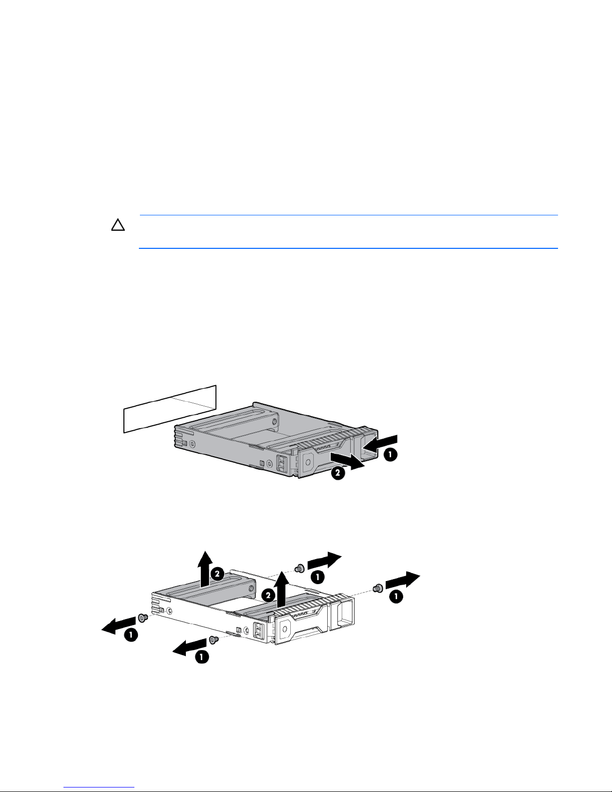
3. Remove the drive carrier.
all bays are populated with either a component or a blank.
a. Disconnect each power cord from the power source.
b. Disconnect each power cord from the server.
4. Remove the two metal brackets from the drive carrier.
Hardware options installation 33
Page 34
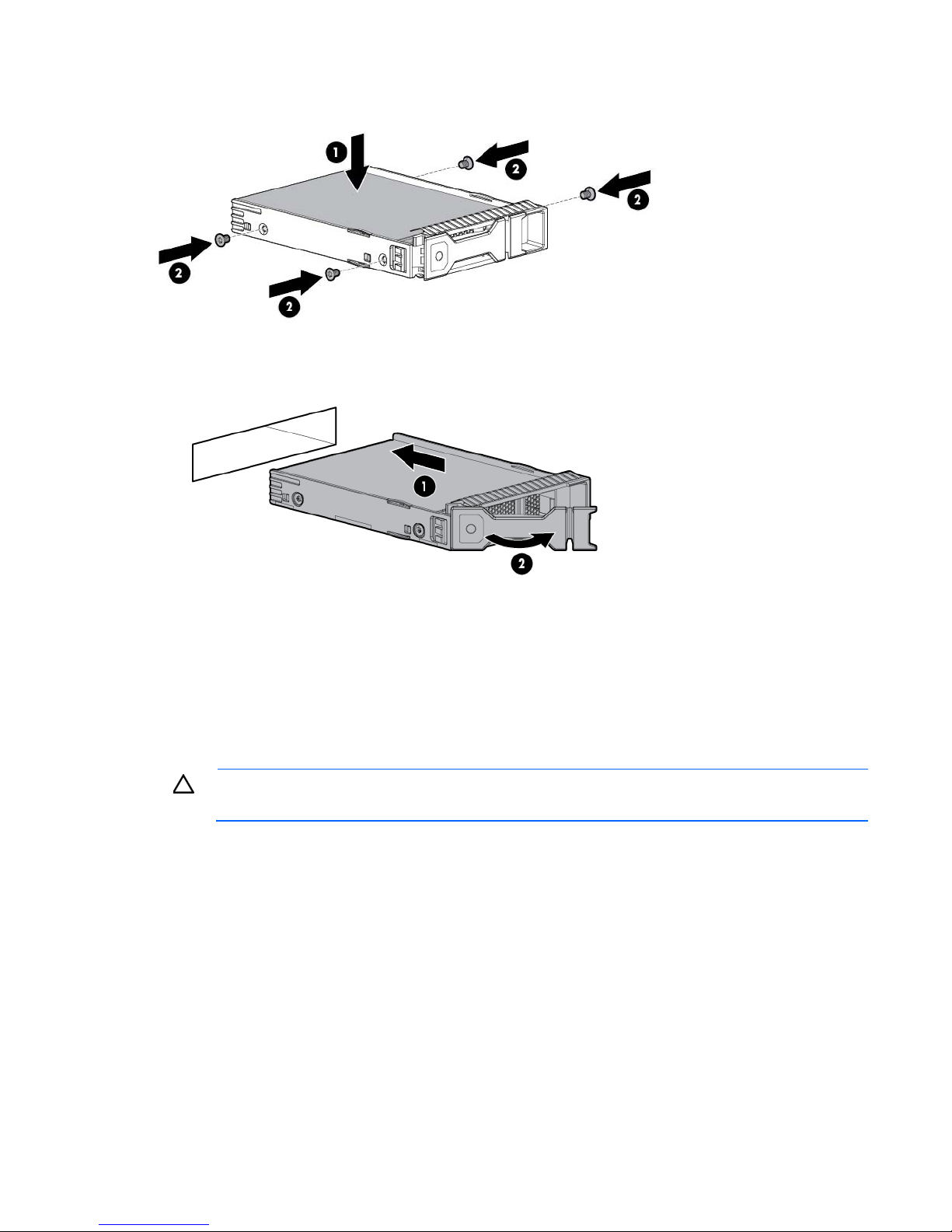
5.
Install the drive in the carrier.
6. Install the drive.
7. Connect each power cord to the server.
8. Connect each power cord to the power source.
9. Power up the server (on page 17).
10. Determine the status of the drive from the drive LED definitions (on page 13).
Installing a hot-plug drive
CAUTION: To prevent improper cooling and thermal damage, do not operate the server unless
To install the component:
all bays are populated with either a component or a blank.
Hardware options installation 34
Page 35
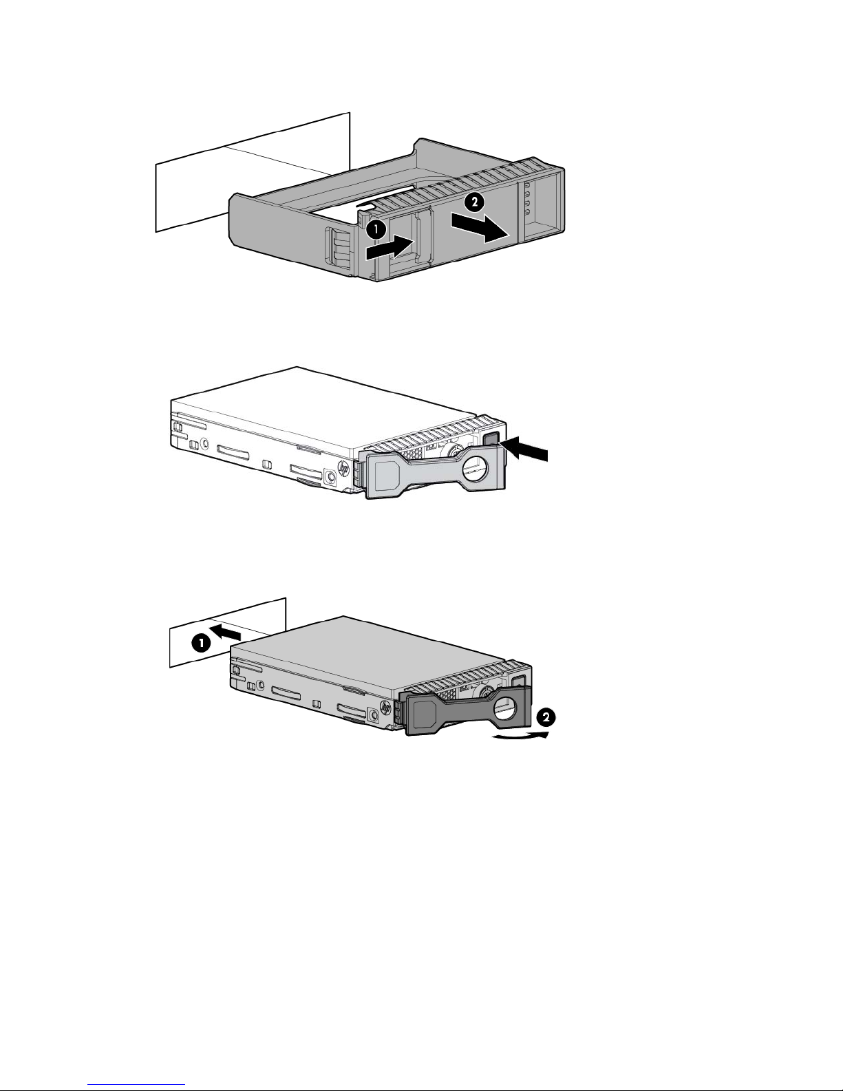
1.
Remove the drive blank.
2. Prepare the drive.
3. Install the drive.
4. Determine the status of the drive from the drive LED definitions (on page 13).
Mini-SAS cable option
To connect the cable option:
1. Power down the server (on page 17).
2. Remove all power:
a. Disconnect each power cord from the power source.
b. Disconnect each power cord from the server.
3. Do one of the following:
Hardware options installation 35
Page 36
o
Extend the server from the rack (on page 17).
o Remove the server from the rack (on page 18).
4. Remove the access panel (on page 19).
5. Remove the PCI riser cage (on page 21).
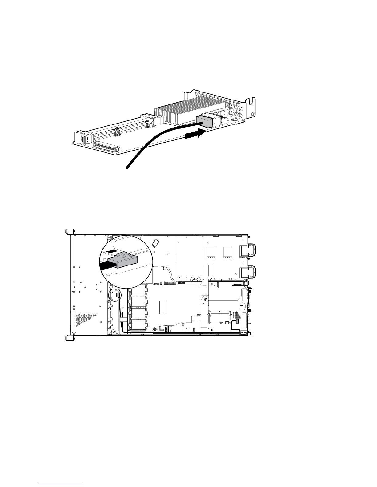
6. Connect the Mini-SAS cable to the storage controller.
7. Install the storage controller ("Installing a storage controller" on page 38).
8. Route the Mini-SAS cable along the side of the system board towards the front chassis, and then connect
the cable to the drive backplane:
o Full-height controller connection
Hardware options installation 36
Page 37
o
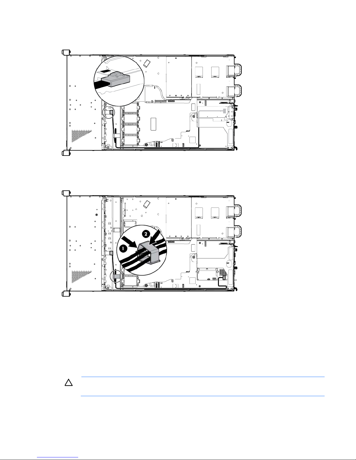
Low-profile controller connection
9. Secure the excess length of the Mini-SAS cable in the cable clip.
10. Connect the rest of the drive cables required in this drive configuration. For more information, see
"Storage cabling (on page 55)."
11. Install the access panel (on page 20).
12. Do one of the following:
o Slide the server into the rack.
o Install the server into the rack ("Installing the server into the rack" on page 28).
13. Install the drives ("Drive options" on page 32).
CAUTION: To prevent improper cooling and thermal damage, do not operate the server unless
all bays are populated with either a component or a blank.
14. Connect each power cord to the server.
15. Connect each power cord to the power source.
Hardware options installation 37
Page 38

16.
After the server is powered down, wait for 30 seconds, and then check the amber LED
before unplugging the cable from the cache module. If the amber LED flashes after 30 seconds,
Power up the server (on page 17).
Controller options
The server ships with an embedded Smart Array B120i controller. For more information about the controller
and its features, see the HP Dynamic Smart Array RAID Controller User Guide on the HP website
(http://www.hp.com/support/DSA_RAID_UG_en).
To configure arrays, see the Configuring Arrays on HP Smart Array Controllers Reference Guide on the HP
website (http://www.hp.com/support/CASAC_RG_en).
Upgrade options exist for the integrated array controller. For a list of supported options, see the QuickSpecs
on the HP website (http://www.hp.com/support).
The server supports FBWC. FBWC consists of a cache module and a capacitor pack. The DDR cache module
buffers and stores data being written by the controller. When the system is powered on, the capacitor pack
fully charges in approximately 5 minutes. If a system power failure occurs, a fully charged capacitor pack
provides power for up to 80 seconds. During that interval, the controller transfers the cached data from DDR
memory to flash memory, where the data remains indefinitely or until a controller retrieves the data.
The data protection and the time limit also apply if a power outage occurs. When power is restored to the
system, an initialization process writes the preserved data to the storage drives.
CAUTION: The cache module connector does not use the industry-standard DDR3 mini-DIMM
pinout. Do not use the controller with cache modules designed for other controller models,
because the controller can malfunction and you can lose data. Also, do not transfer this cache
module to an unsupported controller model, because you can lose data.
CAUTION: To prevent a server malfunction or damage to the equipment, do not add or remove
the capacitor pack while an array capacity expansion, RAID level migration, or stripe size
migration is in progress.
CAUTION:
do not remove the cable from the cache module. The cache module is backing up data. Data will
be lost if the cable is detached when the amber LED is still flashing.
IMPORTANT: The capacitor pack might have a low charge when installed. If the pack does have
low charge a POST error message appears when the server is powered up, indicating that the
capacitor pack is temporarily disabled. No action is necessary. The internal circuitry
automatically recharges the capacitors and enables the capacitor pack. This process might take
up to 4 hours. During this time, the cache module functions properly but without the performance
advantage of the capacitor pack.
Installing a storage controller
HP recommends installing the storage controller option in a full-height expansion slot for better cable routing.
IMPORTANT: For additional installation and configuration information, refer to the
To install the component:
documentation that ships with the option.
Hardware options installation 38
Page 39

1.
Power down the server (on page 17).
2. Remove all power:
a. Disconnect each power cord from the power source.
b. Disconnect each power cord from the server.
3. Do one of the following:
o Extend the server from the rack (on page 17).
o Remove the server from the rack (on page 18).
4. Remove the access panel (on page 19).
5. Install the storage controller ("Expansion board options" on page 48).
6. Connect all necessary internal and external cabling to the storage controller. For more information on
these cabling requirements, see the document the ships with the option. For internal cable routing
information in different drive configuration, see "Storage cabling (on page 55)."
7. Install the access panel (on page 20).
8. Do one of the following:
o Slide the server into the rack.
o Install the server into the rack ("Installing the server into the rack" on page 28).
9. Install the drives ("Drive options" on page 32).
CAUTION: To prevent improper cooling and thermal damage, do not operate the server unless
all bays are populated with either a component or a blank.
10. Connect each power cord to the server.
11. Connect each power cord to the power source.
12. Power up the server (on page 17).
For more information about the controller and its features, see the HP Smart Array Controllers for HP ProLiant
Servers User Guide on the HP website (http://www.hp.com/support/SAC_UG_ProLiantServers_en). To
configure arrays, see the Configuring Arrays on HP Smart Array Controllers Reference Guide on the HP
website (http://www.hp.com/support/CASAC_RG_en).
Upgrade options exist for the integrated array controller. For a list of supported options, see the QuickSpecs
on the HP website (http://www.hp.com/support).
Installing the FBWC module and capacitor pack
CAUTION: In systems that use external data storage, be sure that the server is the first unit to be
powered down and the last to be powered back up. Taking this precaution ensures that the system
To install the component:
does not erroneously mark the drives as failed when the server is powered up.
1. Power down the server (on page 17).
2. Remove all power:
a. Disconnect each power cord from the power source.
b. Disconnect each power cord from the server.
3. Do one of the following:
o Extend the server from the rack (on page 17).
Hardware options installation 39
Page 40
o
Remove the server from the rack (on page 18).
4. Remove the access panel (on page 19).
5. Remove the PCI riser cage (on page 21).
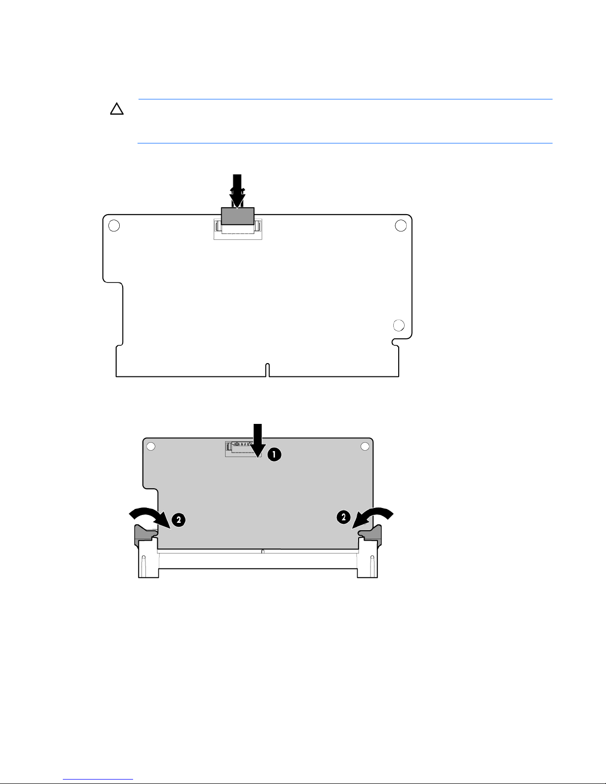
CAUTION: When connecting or disconnecting the capacitor pack cable, the connectors on the
cache module and cable are susceptible to damage. Avoid excessive force and use caution to
6. Connect the capacitor pack cable to the cache module.
avoid damage to these connectors.
7. Install the cache module on the storage controller.
8. Install the storage controller ("Installing a storage controller" on page 38).
9. Route the capacitor pack cable towards the front chassis. For more information on the capacitor pack
cabling in different drive configurations, see "Storage cabling (on page 55)."
10. Install the capacitor pack:
a. Insert the cable end of the capacitor pack in the holder.
Hardware options installation 40
Page 41
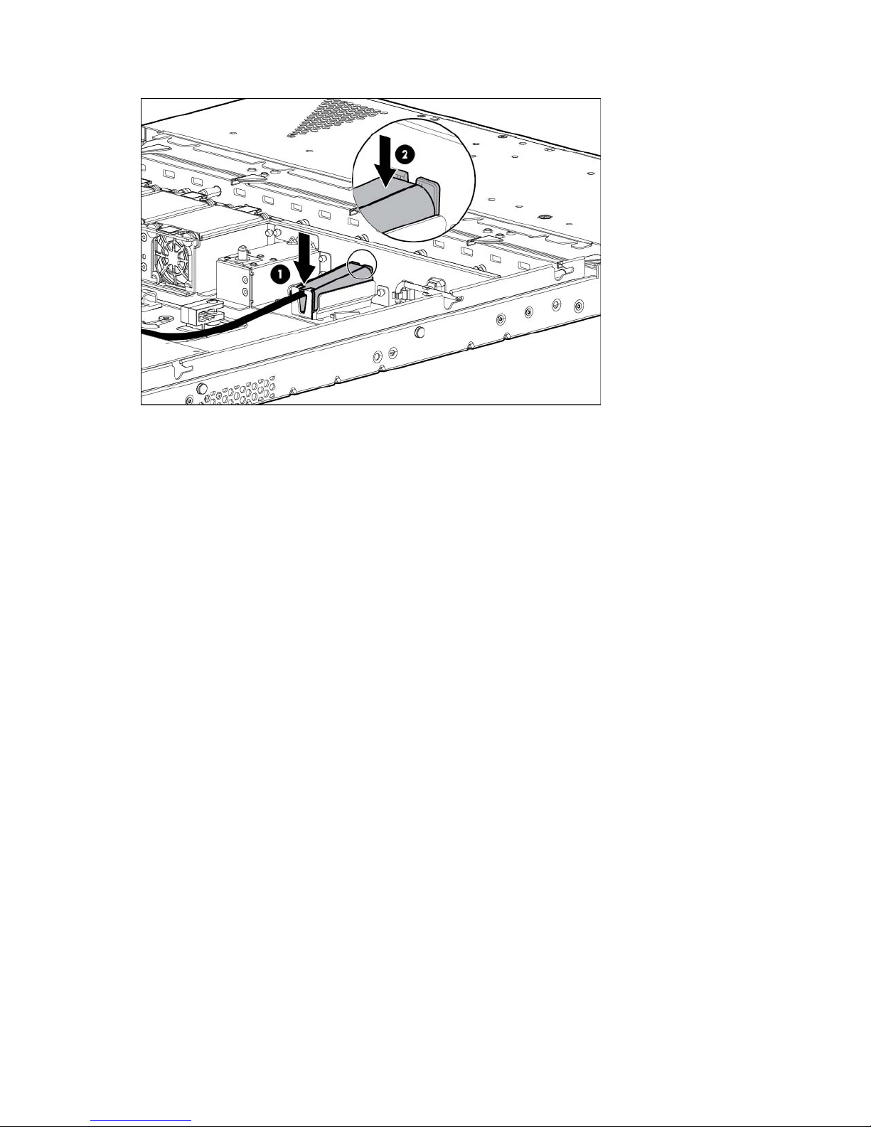
b.
Press the opposite end of the capacitor pack in the holder.
11. Install the access panel (on page 20).
12. Do one of the following:
o Slide the server into the rack.
o Install the server into the rack ("Installing the server into the rack" on page 28).
13. Connect each power cord to the server.
14. Connect each power cord to the power source.
15. Power up the server (on page 17).
Optical drive option
To install the component:
1. Power down the server (on page 17).
2. Remove all power:
a. Disconnect each power cord from the power source.
b. Disconnect each power cord from the server.
3. Do one of the following:
o Extend the server from the rack (on page 17).
o Remove the server from the rack (on page 18).
Hardware options installation 41
Page 42
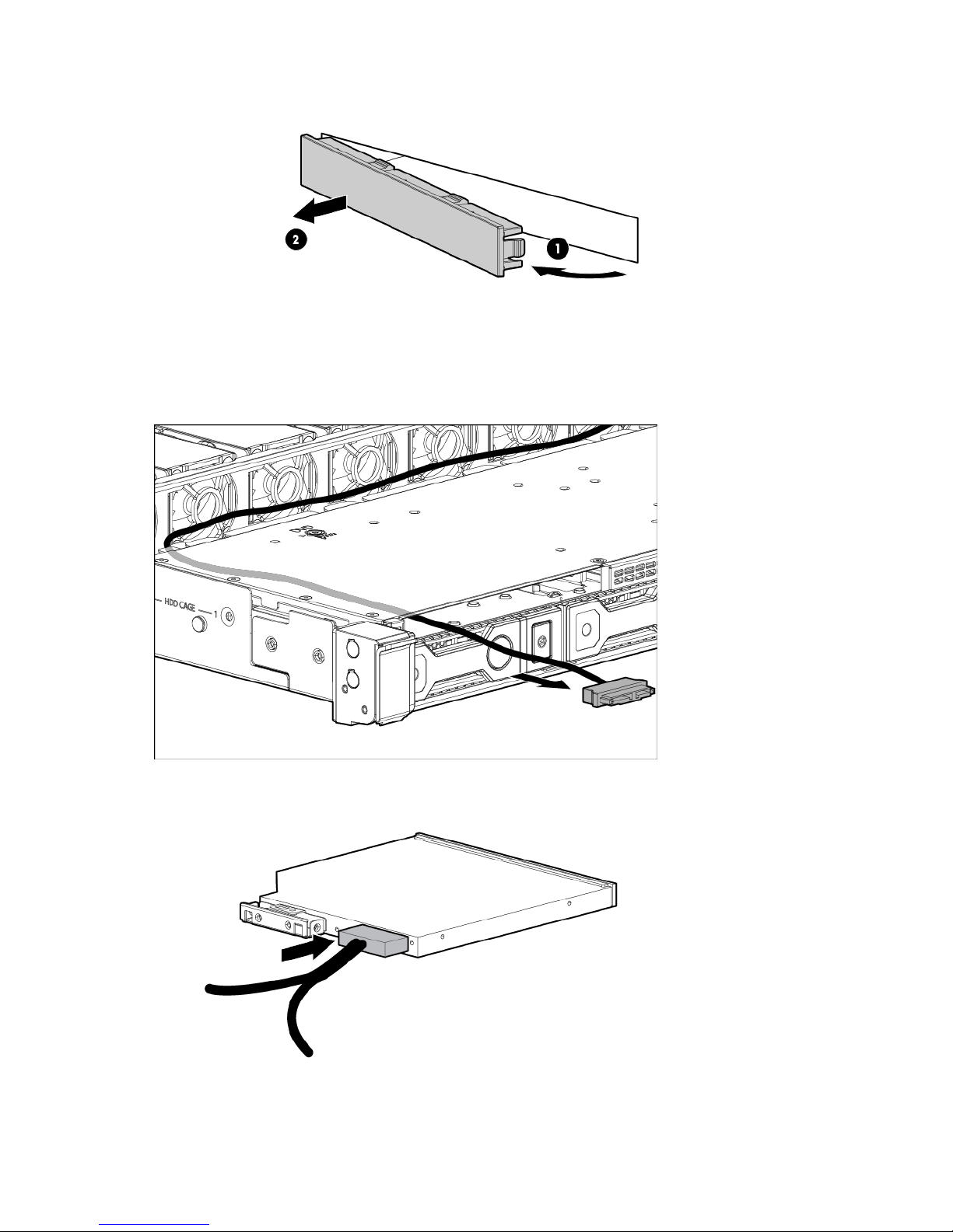
4.
Remove the optical drive blank.
Retain the blank for future use.
5. Remove the access panel (on page 19).
6. If you are installing the optical drive in an LFF drive model, do the following:
a. Thread the optical drive cable through the optical drive bay.
b. Connect the cable to the optical drive.
7. Install the optical drive into the bay, and then secure it with the screw:
Hardware options installation 42
Page 43
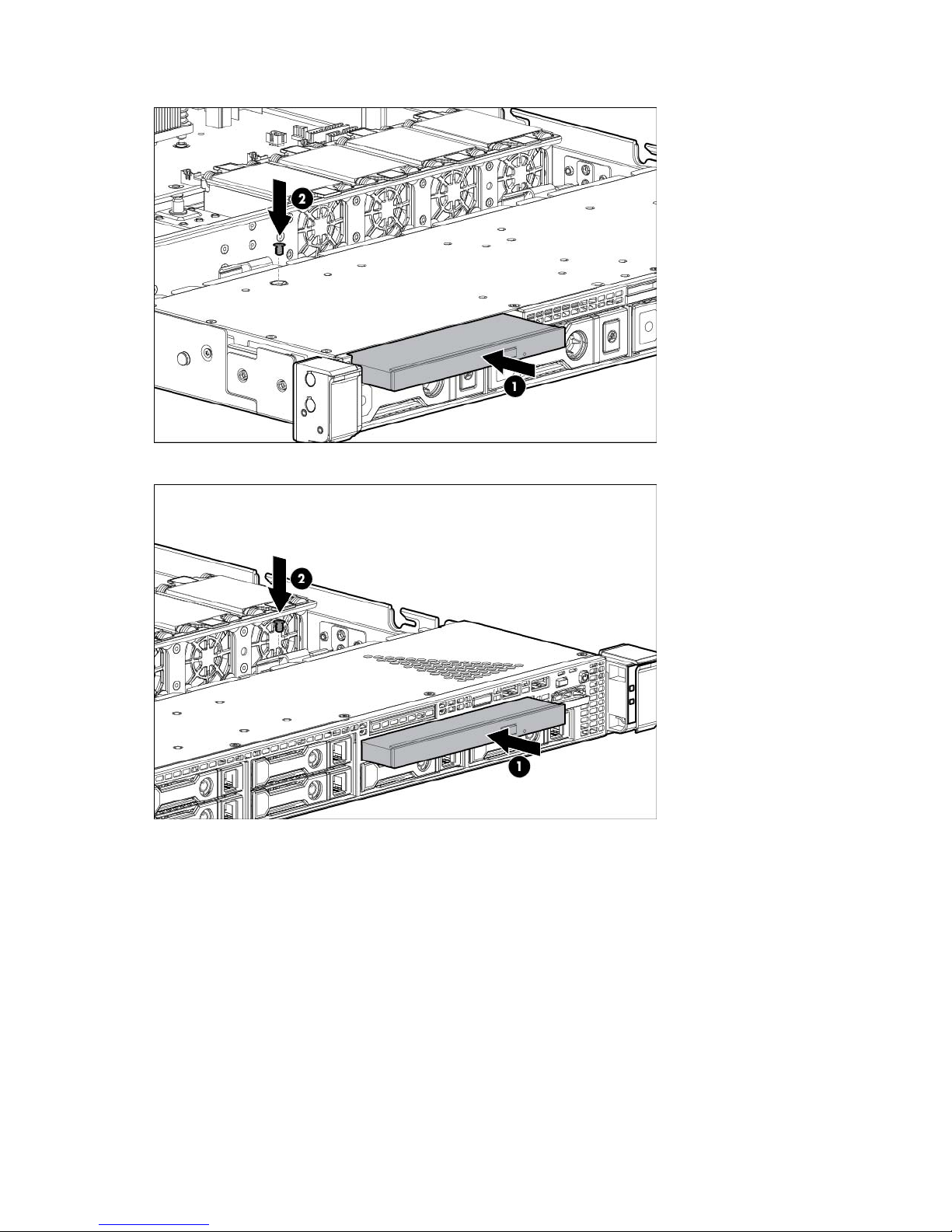
o
Four-bay LFF drive model
o Eight-bay SFF drive model
8. If you are installing the optical drive in an SFF drive model, connect the optical drive cable to the optical
drive.
9. Connect the optical drive cable:
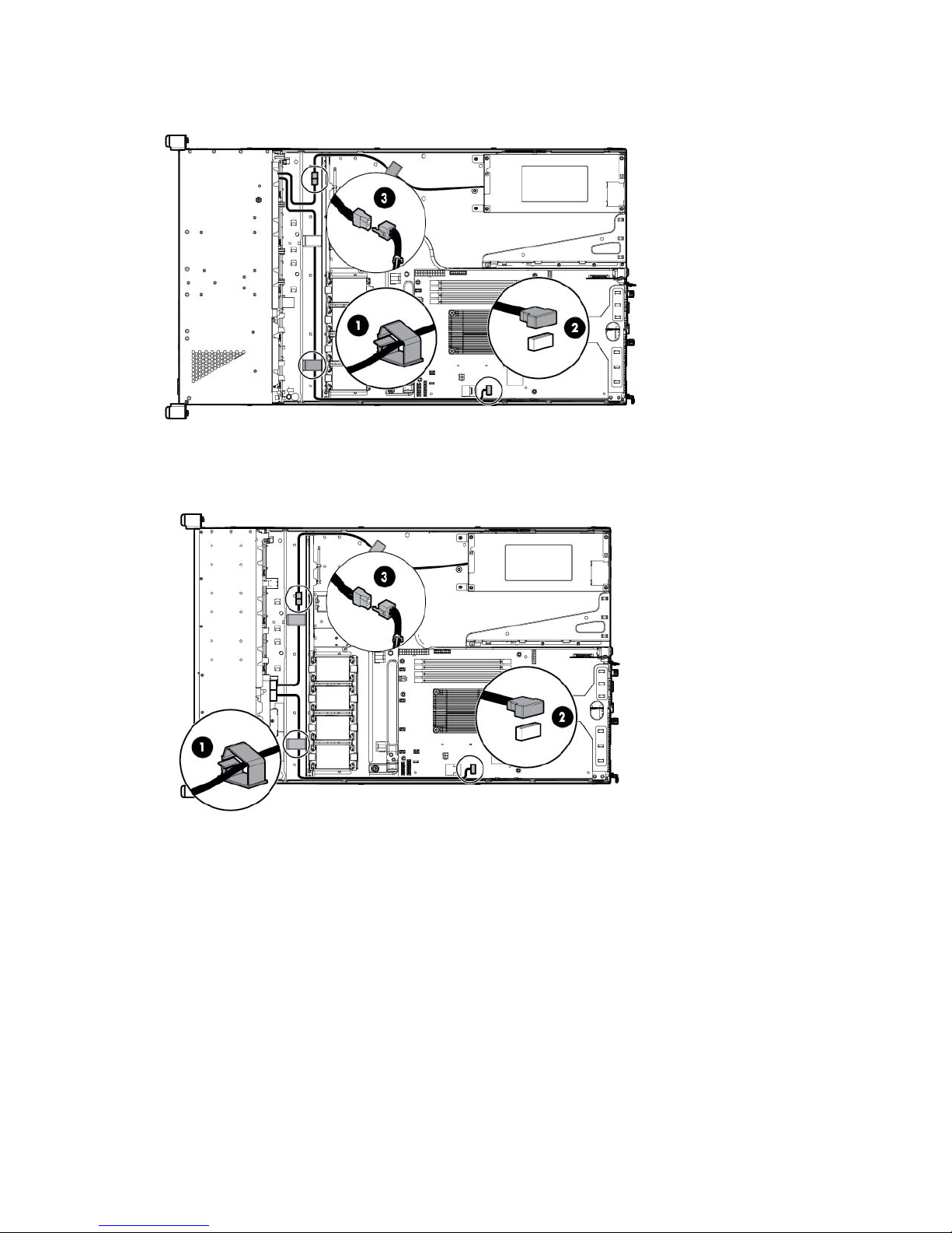
a. Route the optical drive cable through the cable clip on the front chassis.
b. Route the optical drive cable along the side of the system board, and then connect the cable to the
system board.
c. Connect the four-pin (1x4) power supply cable to the power connector of the optical drive cable.
Hardware options installation 43
Page 44
— Four-bay LFF drive model
— Eight-bay SFF drive model
10. Install the access panel (on page 20).
11. Do one of the following:
o Slide the server into the rack.
o Install the server into the rack ("Installing the server into the rack" on page 28).
12. Connect each power cord to the server.
13. Connect each power cord to the power source.
14. Power up the server (on page 17).
Memory options
Hardware options installation 44
Page 45
IMPORTANT: This server does not support mixing LRDIMMs, RDIMMs, or UDIMMs. Attempting
to mix any combination of these DIMMs can cause the server to halt during BIOS initialization.
The server memory subsystem supports UDIMMs only. UDIMMs represent the most basic type of memory
module and offer lower latency and (relatively) low power consumption, but are limited in capacity.
The server supports dual-rank, PC3-10600E/PC3-12800E (DDR3 ECC) DIMMs operating at 1333 or 1600
MHz speed.
Depending on the processor model and the number of DIMMs installed, the memory clock speed might be
reduced to 1333 or 1066 MHz. For more information, see "General DIMM slot population guidelines (on
page 46)."
HP SmartMemory
HP SmartMemory, introduced for Gen8 servers, authenticates and unlocks certain features available only on
HP Qualified memory and verifies whether installed memory has passed HP qualification and test processes.
Qualified memory is performance-tuned for HP ProLiant and BladeSystem servers and provides future
enhanced support through HP Active Health and manageability software.
Certain performance features are unique with HP SmartMemory. The industry supports UDIMM at 2 DIMMs
per channel at 1066 MT/s. HP SmartMemory supports 2 DIMMs per channel at 1333 MT/s, or 25% greater
bandwidth.
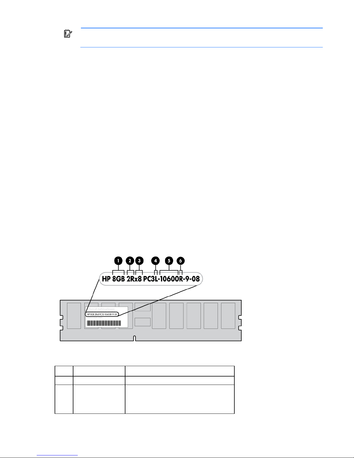
DIMM identification
To determine DIMM characteristics, use the label attached to the DIMM and the following illustration and
table.
Item Description Definition
1
2
Size —
Rank 1R = Single-rank
2R = Dual-rank
3R = Three-rank
4R = Quad-rank
Hardware options installation 45
Page 46
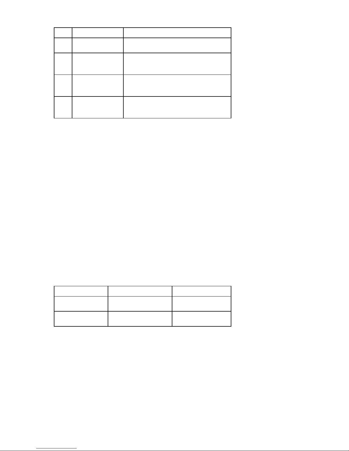
Item Description Definition
3
4
5
6
Data width x4 = 4-bit
x8 = 8-bit
Voltage rating L = Low voltage (1.35V)
U = Ultra low voltage (1.25V)
Blank or omitted = Standard
Memory speed 12800 = 1600-MT/s
10600 = 1333-MT/s
8500 = 1066-MT/s
DIMM type R = RDIMM (registered)
E = UDIMM (unbuffered with ECC)
L = LRDIMM (load reduced)
For the latest supported memory information, see the QuickSpecs on the HP website
(http://h18000.www1.hp.com/products/quickspecs/ProductBulletin.html). At the website, choose the
geographic region, and then locate the product by name or product category.
Single-rank and dual-rank DIMMs
DIMM configuration requirements are based on these classifications:
• Single-rank DIMM—One set of memory chips that is accessed while writing to or reading from the
memory.
• Dual-rank DIMM—Two single-rank DIMMs on the same module, with only one rank accessible at a time.
The server memory control subsystem selects the proper rank within the DIMM when writing to or reading
from the DIMM.
Dual-rank DIMMs provide the greatest capacity with the existing memory technology. For example, if current
DRAM technology supports 2-GB single-rank DIMMs, a dual-rank DIMM would be 4 GB.
Memory subsystem architecture
The memory subsystem in this server is divided into channels. The processor supports two channels, and each
channel supports two DIMM slots.
Channel Population order Slot number
1
2
The server supports a maximum of 32 GB, using 2 GB, 4 GB, and 8 GB single-rank or dual-rank UDIMMs.
DIMM slots in this server are identified by number and by letter. Letters identify the population order. Slot
numbers are reported by ROM messages during boot and for error reporting. For the DIMM slot locations,
see "DIMM slot locations (on page 11)."
C
A
D
B
4
3
2
1
General DIMM slot population guidelines
• The server has four memory slots.
• The server supports two channels with two DIMM slots per channel.
Hardware options installation 46
Page 47

o
Memory channel 1 consists of the two DIMMs that are closest to the processor.
o Memory channel 2 consists of the two DIMMs that are located farthest from the processor.
• White DIMM slot indicate the first slot of a channel (3-A, 1-B).
• Memory speed support depends on the type of processor installed. See the technical specification of the
installed processor for more information.
• The server supports up to 1600 MT/s ECC UDIMMs.
• The server supports up to 32 GB (4x8 GB) UDIMMs.
• The server does not support:
o RDIMMs
o Non-ECC UDIMMs
o Elpida DIMMs
• When installing DIMMs:
o Populate the DIMM slots in this sequence: 3-A, 1-B, 4-C, 2-D.
o Use HP-qualified UDIMMs.
For detailed memory configuration rules and guidelines, use the Online DDR3 Memory Configuration Tool
on the HP website (http://www.hp.com/go/ddr3memory-configurator).
Installing a DIMM
1. Power down the server (on page 17).
2. Remove all power:
a. Disconnect each power cord from the power source.
b. Disconnect each power cord from the server.
3. Do one of the following:
o Extend the server from the rack (on page 17).
o Remove the server from the rack (on page 18).
4. Remove the access panel (on page 19).
5. Remove the air baffle (on page 20).
6. Open the DIMM slot latches.
Hardware options installation 47
Page 48
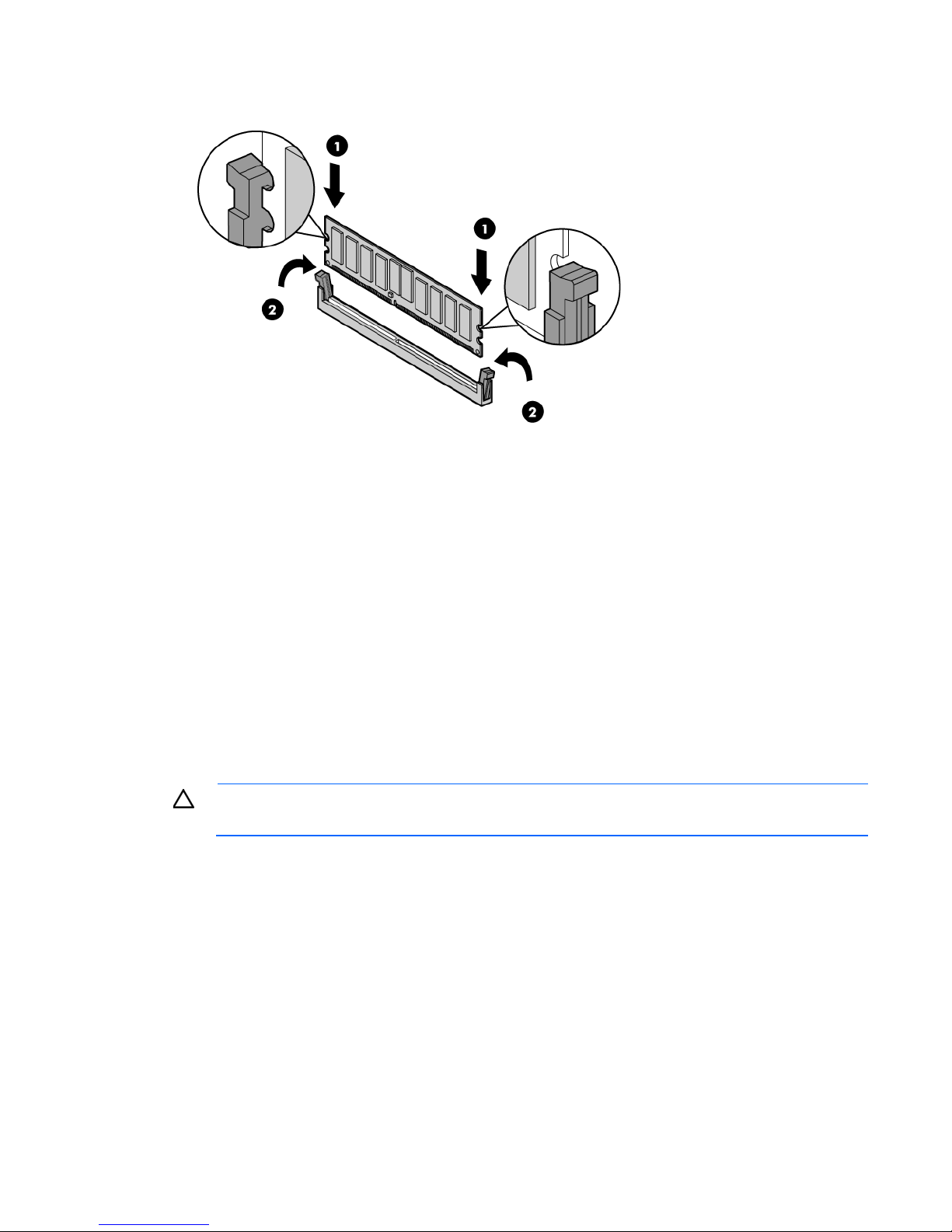
7.
Install the DIMM.
8. Install the air baffle (on page 21).
9. Install the access panel (on page 20).
10. Do one of the following:
o Slide the server into the rack.
o Install the server into the rack ("Installing the server into the rack" on page 28).
11. Connect each power cord to the server.
12. Connect each power cord to the power source.
13. Power up the server (on page 17).
Expansion board options
The server has both full-height and low-profile expansion slots for controller option installation ("PCIe riser
board slot definitions" on page 11).
CAUTION: To prevent improper cooling and thermal damage, do not operate the server unless
To install the component:
1. Power down the server (on page 17).
2. Remove all power:
all expansion slots have either an expansion slot cover or an expansion board installed.
a. Disconnect each power cord from the power source.
b. Disconnect each power cord from the server.
3. Do one of the following:
o Extend the server from the rack (on page 17).
o Remove the server from the rack (on page 18).
4. Remove the access panel (on page 19).
5. Remove the PCI riser cage (on page 21).
Hardware options installation 48
Page 49
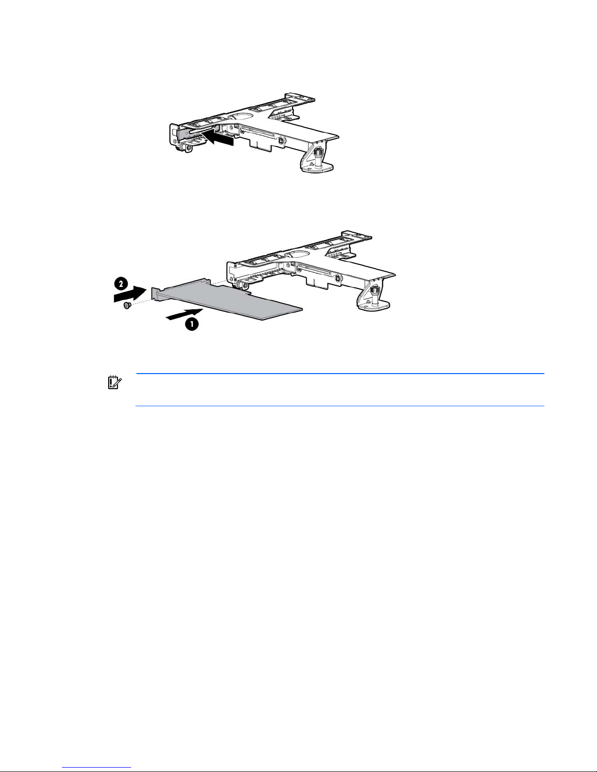
6.
Identify the expansion slot compatible with the new option, and then remove the cover opposite that
slot.
7. Install the expansion board.
8. Install the PCI riser cage (on page 22).
IMPORTANT: The server does not power up if the PCI riser cage is not seated properly.
9. Connect all necessary internal and external cables to the expansion board. For more information on
these cabling requirements, see the documentation that ships with the option.
10. Install the access panel (on page 20).
11. Do one of the following:
o Slide the server into the rack.
o Install the server into the rack ("Installing the server into the rack" on page 28).
12. Connect each power cord to the server.
13. Connect each power cord to the power source.
14. Power up the server (on page 17).
Dedicated iLO management port option
To install the component:
1. Power down the server (on page 17).
2. Remove all power:
a. Disconnect each power cord from the power source.
b. Disconnect each power cord from the server.
3. Do one of the following:
Hardware options installation 49
Page 50
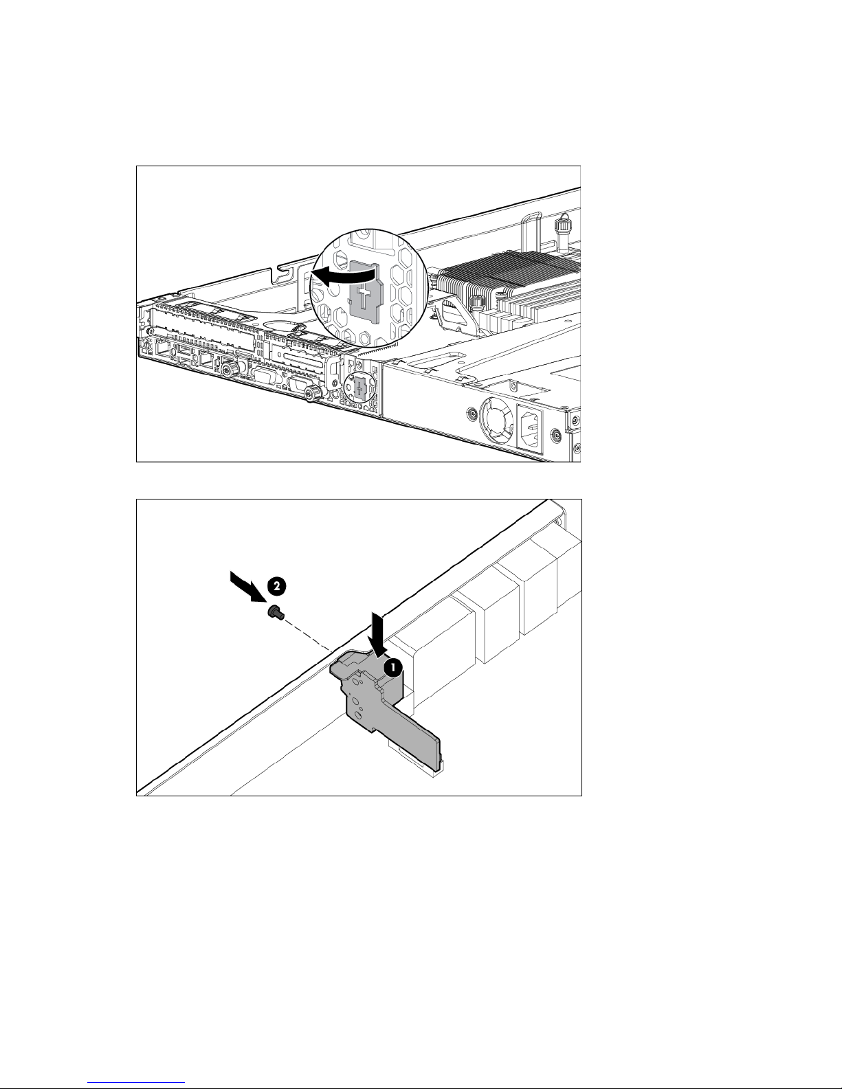
o
Extend the server from the rack (on page 17).
o Remove the server from the rack (on page 18).
4. Remove the access panel (on page 19).
5. Using a flat screwdriver, toggle the knockout to loosen it, and then pull it out of the chassis.
6. Install the dedicated iLO management module.
7. Install the access panel (on page 20).
8. Do one of the following:
o Slide the server into the rack.
o Install the server into the rack ("Installing the server into the rack" on page 28).
9. Connect each power cord to the server.
10. Connect each power cord to the power source.
11. Power up the server (on page 17).
Hardware options installation 50
Page 51

Enabling the dedicated iLO management port
If the iLO RBSU settings are reset to the default values, access to the machine will be
The onboard NIC 1/shared iLO connector is set as the default system iLO port.
To enable the installed dedicated iLO module:
1. During the server startup sequence after module installation, to access iLO RBSU, press the F8 key.
2. Select the Network menu.
3. Click the Network Interface Adapter field.
4. To change the setting to ON, press the spacebar.
5. To save the new settings, press the F10 key.
6. Select the File menu, and then to close iLO RBSU, click Exit.
7. To confirm exiting iLO RBSU, click OK. The server automatically reboots.
IMPORTANT:
lost. Access the physical machine, and then set the Network Interface Adapter field to ON.
HP Trusted Platform Module option
Use these instructions to install and enable a TPM on a supported server. This procedure includes three
sections:
1. Installing the Trusted Platform Module board.
2. Retaining the recovery key/password (on page 53).
3. Enabling the Trusted Platform Module (on page 53).
Enabling the TPM requires accessing RBSU ("HP ROM-Based Setup Utility" on page 67). For more
information about RBSU, see the HP website (http://www.hp.com/go/ilomgmtengine/docs).
TPM installation requires the use of drive encryption technology, such as the Microsoft Windows BitLocker
Drive Encryption feature. For more information on BitLocker, see the Microsoft website
(http://www.microsoft.com).
CAUTION: Always observe the guidelines in this document. Failure to follow these guidelines
can cause hardware damage or halt data access.
When installing or replacing a TPM, observe the following guidelines:
• Do not remove an installed TPM. Once installed, the TPM becomes a permanent part of the system
board.
• When installing or replacing hardware, HP service providers cannot enable the TPM or the encryption
technology. For security reasons, only the customer can enable these features.
• When returning a system board for service replacement, do not remove the TPM from the system board.
When requested, HP Service provides a TPM with the spare system board.
• Any attempt to remove an installed TPM from the system board breaks or disfigures the TPM security
rivet. Upon locating a broken or disfigured rivet on an installed TPM, administrators should consider the
system compromised and take appropriate measures to ensure the integrity of the system data.
• When using BitLocker, always retain the recovery key/password. The recovery key/password is
required to enter Recovery Mode after BitLocker detects a possible compromise of system integrity.
Hardware options installation 51
Page 52
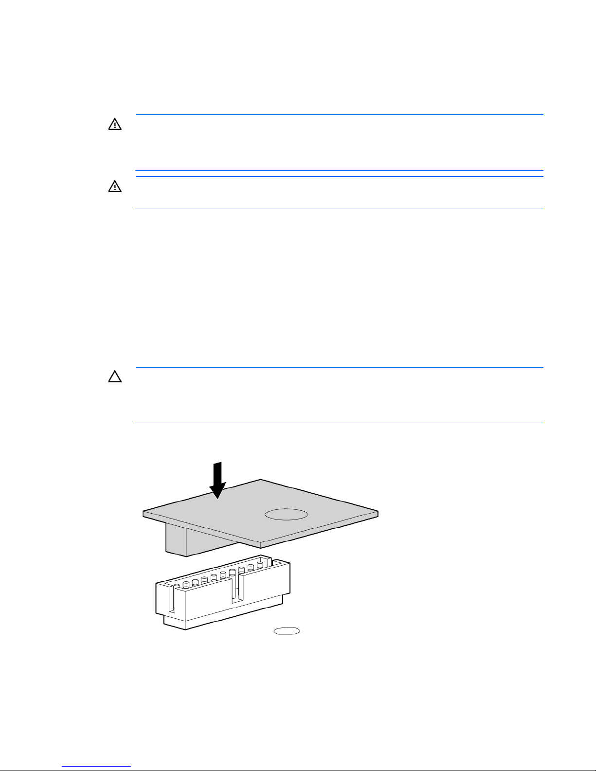
• HP is not liable for blocked data access caused by improper TPM use. For operating instructions, see the
encryption technology feature documentation provided by the operating system.
Installing the Trusted Platform Module board
WARNING: To reduce the risk of personal injury, electric shock, or damage to the equipment,
remove the power cord to remove power from the server. The front panel Power On/Standby
button does not completely shut off system power. Portions of the power supply and some internal
To install the component:
1. Power down the server (on page 17).
2. Remove all power:
3. Do one of the following:
4. Remove the access panel (on page 19).
5. Install the TPM board. Press down on the connector to seat the board ("System board components" on
circuitry remain active until AC power is removed.
WARNING: To reduce the risk of personal injury from hot surfaces, allow the drives and the
internal system components to cool before touching them.
a. Disconnect each power cord from the power source.
b. Disconnect each power cord from the server.
o Extend the server from the rack (on page 17).
o Remove the server from the rack (on page 18).
CAUTION: Any attempt to remove an installed TPM from the system board breaks or disfigures
the TPM security rivet. Upon locating a broken or disfigured rivet on an installed TPM,
administrators should consider the system compromised and take appropriate measures to ensure
the integrity of the system data.
page 10).
Hardware options installation 52
Page 53
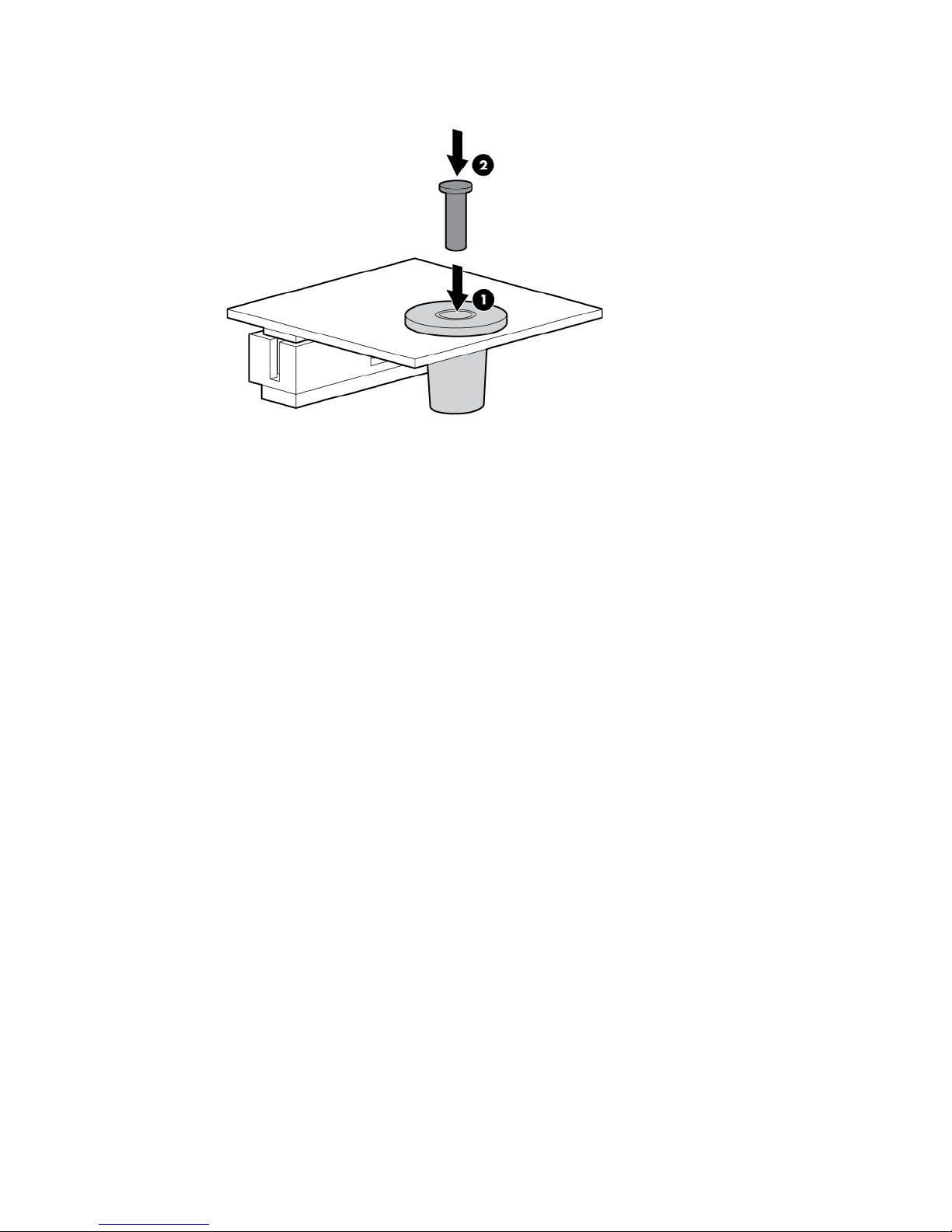
6.
Install the TPM security rivet by pressing the rivet firmly into the system board.
7. Install the access panel (on page 20).
8. Do one of the following:
o Slide the server into the rack.
o Install the server into the rack ("Installing the server into the rack" on page 28).
9. Connect each power cord to the server.
10. Connect each power cord to the power source.
11. Power up the server (on page 17).
Retaining the recovery key/password
The recovery key/password is generated during BitLocker™ setup, and can be saved and printed after
BitLocker™ is enabled. When using BitLocker™, always retain the recovery key/password. The recovery
key/password is required to enter Recovery Mode after BitLocker™ detects a possible compromise of system
integrity.
To help ensure maximum security, observe the following guidelines when retaining the recovery
key/password:
• Always store the recovery key/password in multiple locations.
• Always store copies of the recovery key/password away from the server.
• Do not save the recovery key/password on the encrypted hard drive.
Enabling the Trusted Platform Module
1. When prompted during the start-up sequence, access RBSU by pressing the F9 key.
2. From the Main Menu, select Server Security.
3. From the Server Security Menu, select Trusted Platform Module.
4. From the Trusted Platform Module Menu, select TPM Functionality.
5. Select Enable, and then press the Enter key to modify the TPM Functionality setting.
Hardware options installation 53
Page 54

6.
When a TPM is installed and enabled on the server, data access is locked if you fail
to follow the proper procedures for updating the system or option firmware, replacing the system
Press the Esc key to exit the current menu, or press the F10 key to exit RBSU.
7. Reboot the server.
8. Enable the TPM in the OS. For OS-specific instructions, see the OS documentation.
CAUTION:
board, replacing a hard drive, or modifying OS application TPM settings.
For more information on firmware updates and hardware procedures, see the HP Trusted Platform Module
Best Practices White Paper on the HP website (http://www.hp.com/support).
For more information on adjusting TPM usage in BitLocker™, see the Microsoft website
(http://technet.microsoft.com/en-us/library/cc732774.aspx).
Hardware options installation 54
Page 55
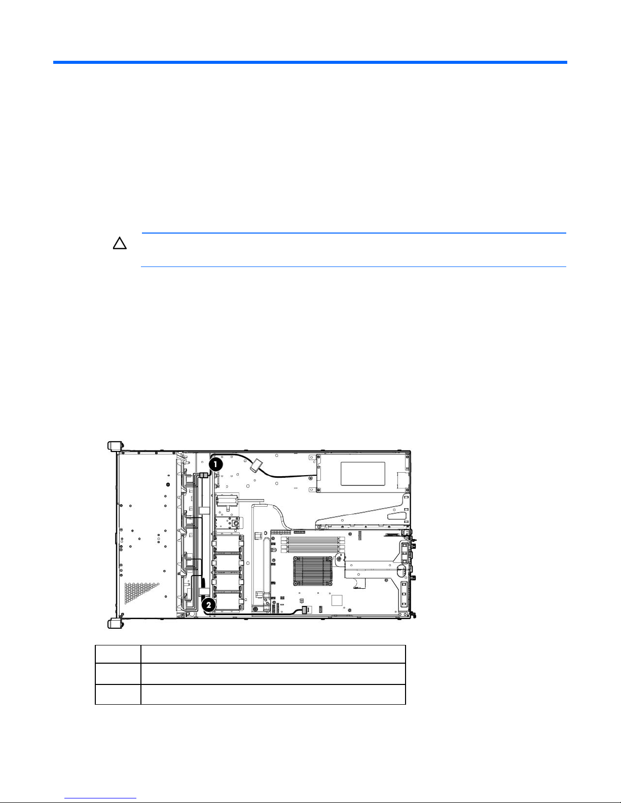
Cabling
Cabling overview
This section provides guidelines that help you make informed decisions about cabling the server and
hardware options to optimize performance.
For information on cabling peripheral components, refer to the white paper on high-density deployment at
the HP website (http://www.hp.com/products/servers/platforms).
CAUTION: When routing cables, always be sure that the cables are not in a position where they
Storage cabling
can be pinched or crimped.
The FBWC capacitor pack cabling is shown in the following images. The FBWC solution is a separately
purchased option. Capacitor pack cabling is only supported in Smart Array controller options that support
FBWC installation.
Four-bay LFF non-hot-plug drive cage cabling
• Mini-SAS cable connected to the system board
Item Description
1
2
Power cable
700-mm Mini-SAS cable for non-hot-plug drive configuration
Cabling 55
Page 56
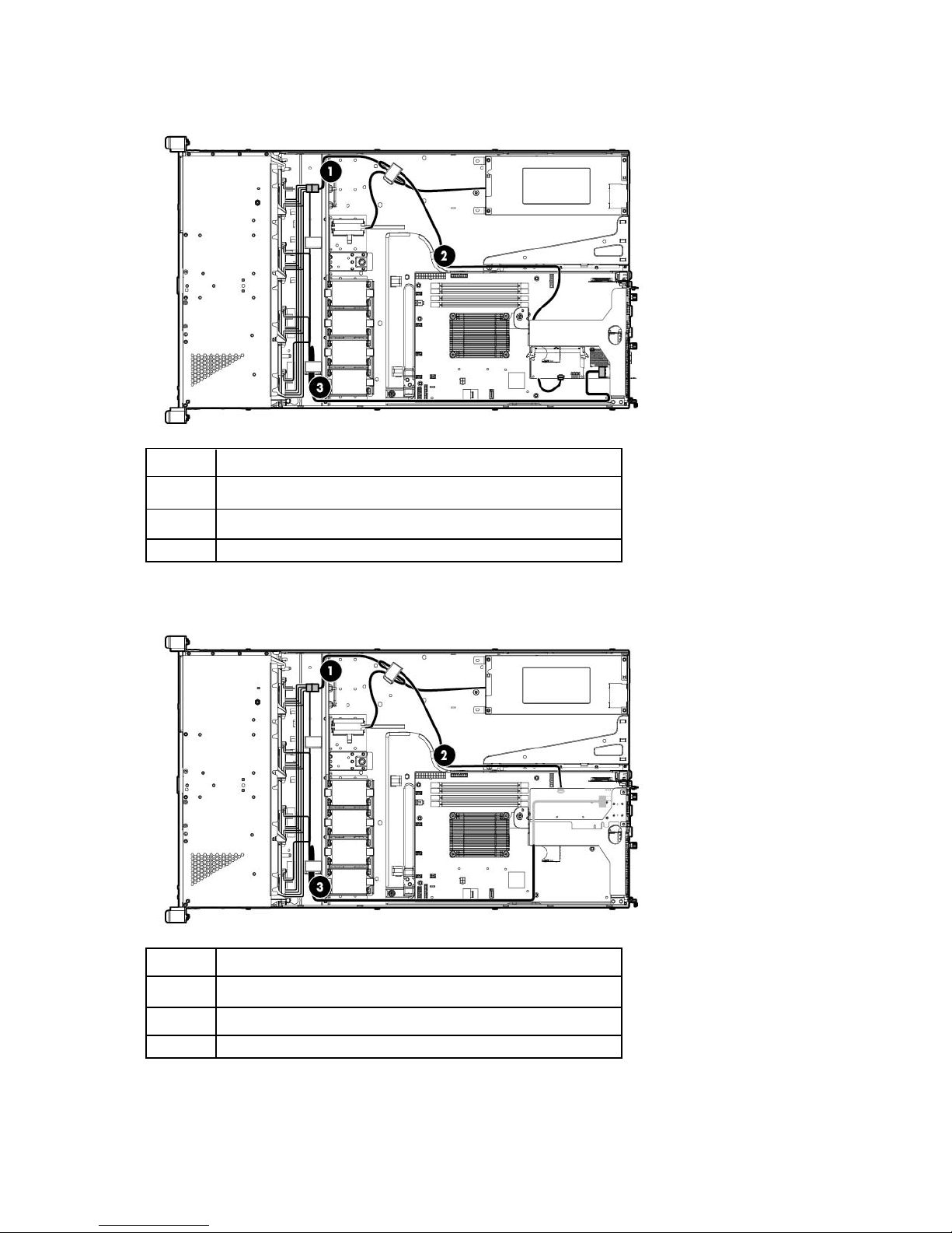
• Mini-SAS cable connected to a storage controller in the full-height expansion slot
Item Description
1
Power cable
2
3
Capacitor pack cable
700-mm Mini-SAS cable for non-hot-plug drive configuration
• Mini-SAS cable connected to a storage controller in the low-profile expansion slot
Item Description
1
Power cable
2
3
Capacitor pack cable
700-mm Mini-SAS cable for non-hot-plug drive configuration
Cabling 56
Page 57
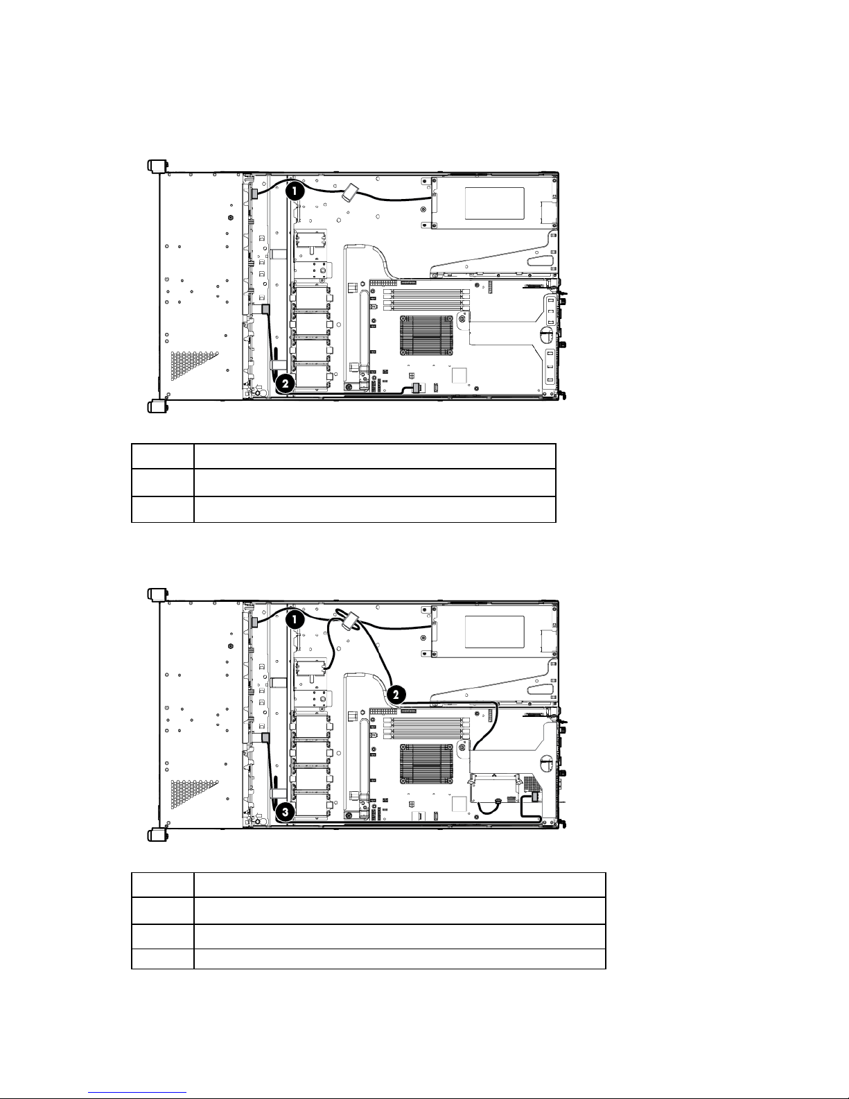
Four-bay LFF hot-plug drive cage cabling
• Mini-SAS cable connected to the system board
Item Description
1
2
Power cable
560-mm Mini-SAS cable
• Mini-SAS cable connected to a storage controller in the full-height expansion slot
Item Description
1
2
3
Power cable
Capacitor pack cable
890-mm Mini-SAS cable
Cabling 57
Page 58
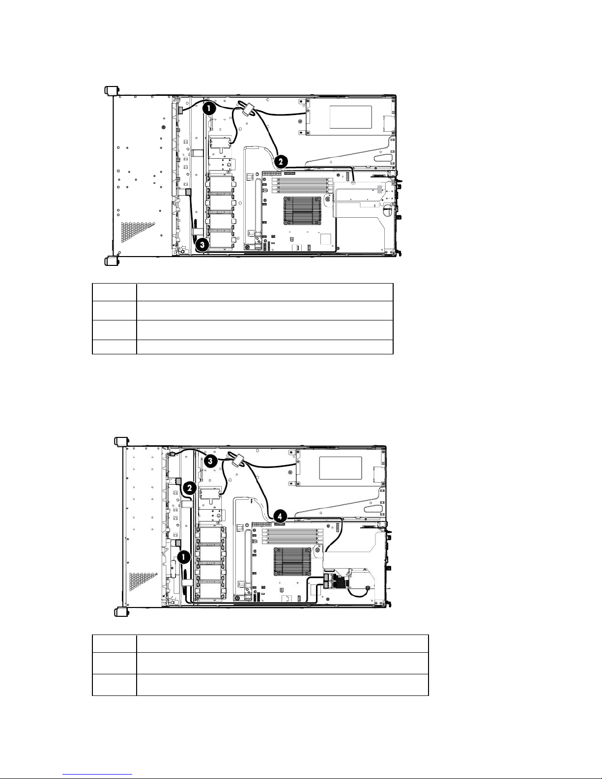
• Mini-SAS cable connected to a storage controller in the low-profile expansion slot
Item Description
1
Power cable
2
3
Capacitor pack cable
890-mm Mini-SAS cable
Eight-bay SFF hot-plug drive cage cabling
• Mini-SAS cables connected to a storage controller in the full-height expansion slot
Item Description
1
2
560-mm Mini-SAS cable
700-mm Mini-SAS cable for hot-plug drive configuration
Cabling 58
Page 59
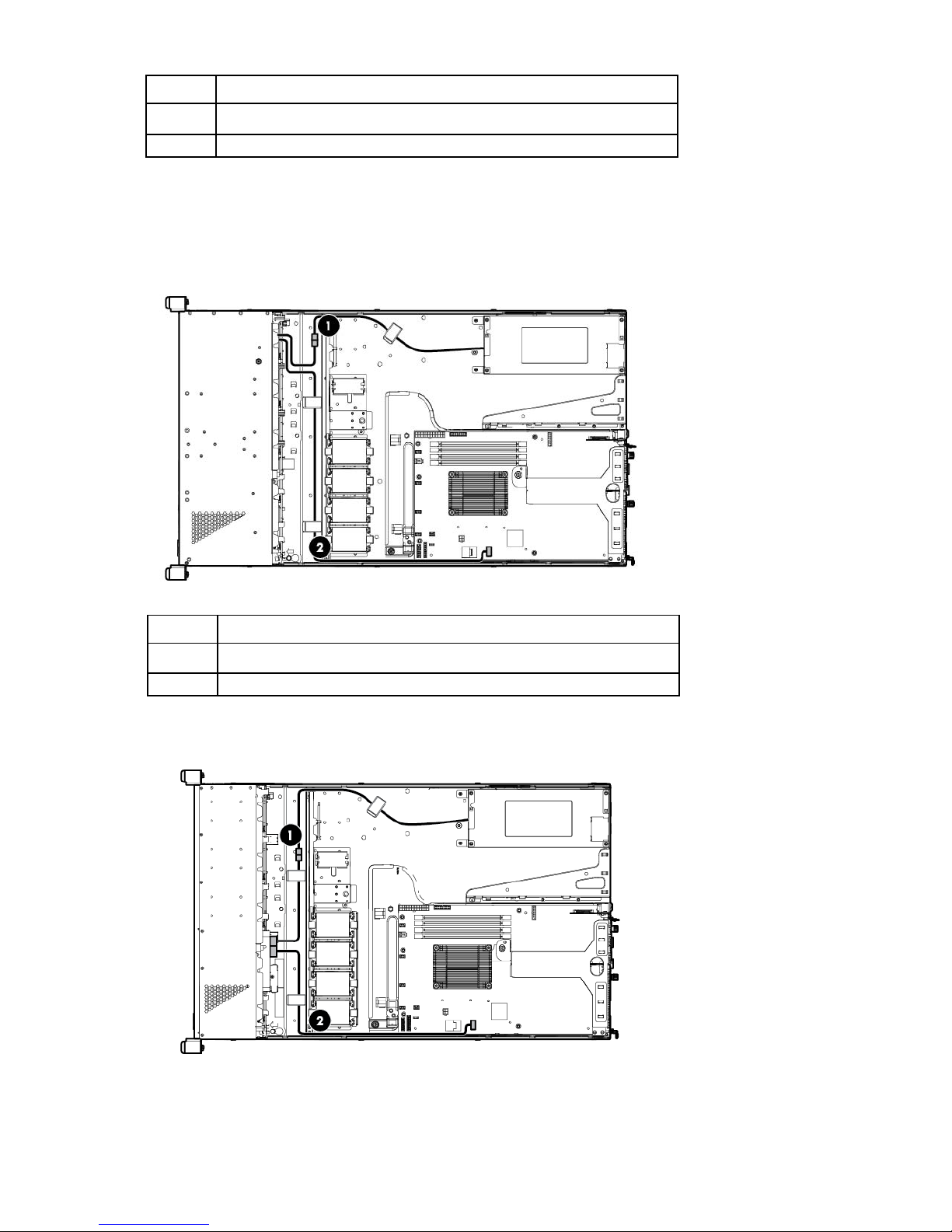
Item Description
3
Power cable
4
Capacitor pack cable
Optical drive cabling
• LFF drive cage model
Item Description
1
2
Optical drive power cable
Optical drive SATA cable
• SFF drive cage model
Cabling 59
Page 60
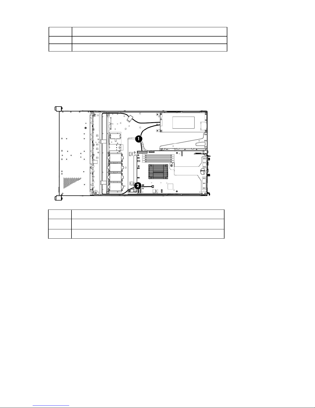
Item Description
1
2
Optical drive power cable
Optical drive SATA cable
Power supply cabling
Nonredundant power supply cabling
Item Description
1
2
24-pin power supply cable
4-pin power supply cable
Cabling 60
Page 61
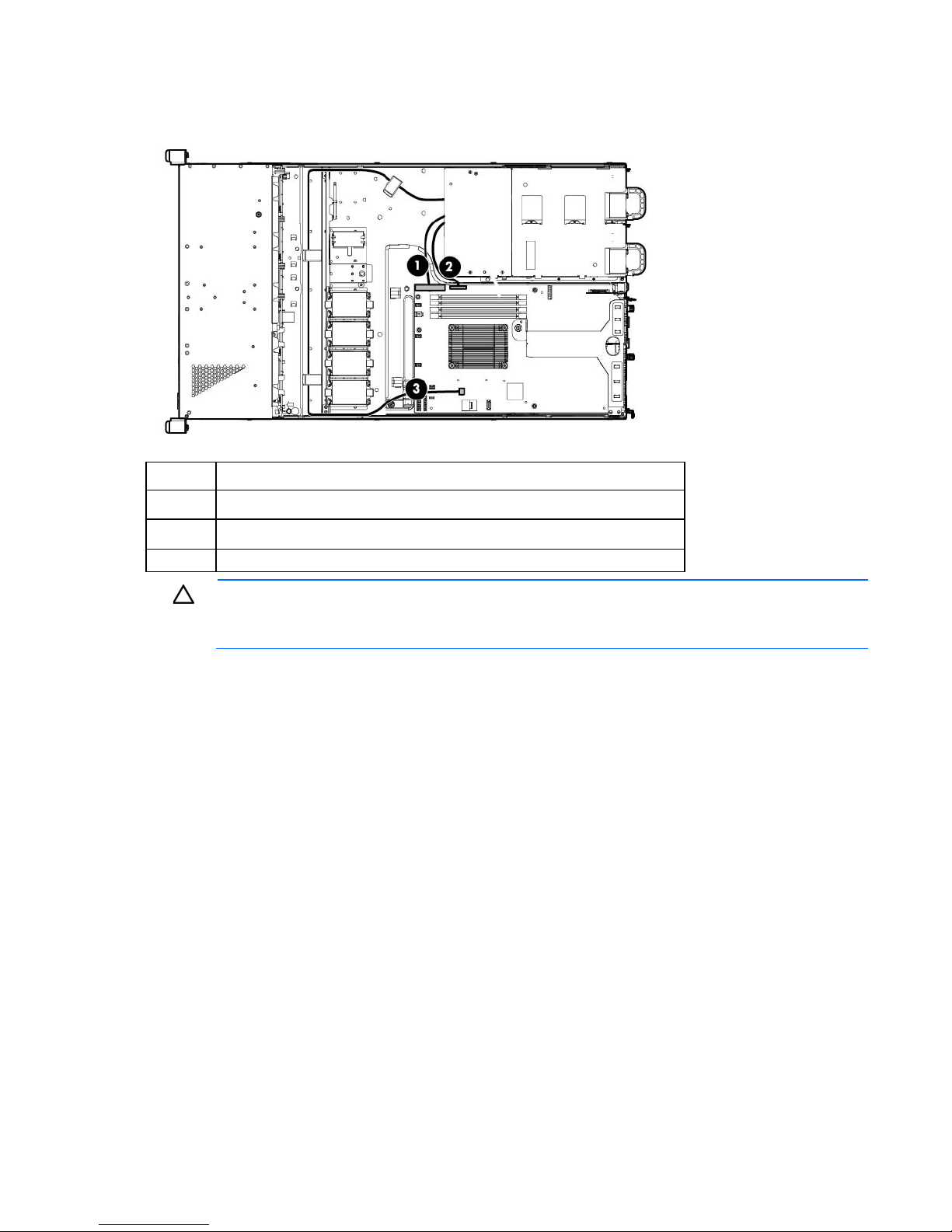
Redundant power supply cabling
Item Description
1
2
24-pin power supply cable
26-pin RPS cable
3
CAUTION: The default and redundant power supplies in the server must have the same output
power capacity. Verify that all power supplies have the same part number and label color. The
4-pin power supply cable
system becomes unstable and might shut down when it detects mismatched power supplies.
Cabling 61
Page 62

Software and configuration utilities
Online and Offline
Offline
Server mode
The software and configuration utilities presented in this section operate in online mode, offline mode, or in
both modes.
Software or configuration utility Server mode
HP iLO (on page 62)
Active Health System (on page 63)
Integrated Management Log (on page 64)
Intelligent Provisioning (on page 64)
HP Insight Diagnostics (on page 65)
HP Insight Remote Support software (on page 66)
Erase Utility (on page 65)
Scripting Toolkit (on page 66)
HP Service Pack for ProLiant (on page 67)
HP Smart Update Manager (on page 67)
HP ROM-Based Setup Utility (on page 67)
Array Configuration Utility (on page 69)
Option ROM Configuration for Arrays (on page 70)
ROMPaq utility (on page 71)
Server QuickSpecs
For more information about product features, specifications, options, configurations, and compatibility, see
the QuickSpecs on the HP website (http://www.hp.com/go/productbulletin). At the website, choose the
geographic region, and then locate the product by name or product category.
Online and Offline
Online and Offline
Online and Offline
Offline
Online
Offline
Online
Online and Offline
Online and Offline
Offline
Online and Offline
Offline
HP iLO Management Engine
The HP iLO Management Engine is a set of embedded management features supporting the complete
HP iLO
lifecycle of the server, from initial deployment through ongoing management.
The iLO subsystem is a standard component of selected HP ProLiant servers that simplifies initial server setup,
server health monitoring, power and thermal optimization, and remote server administration. The iLO
subsystem includes an intelligent microprocessor, secure memory, and a dedicated network interface. This
design makes iLO independent of the host server and its operating system.
Software and configuration utilities 62
Page 63

iLO enables and manages the Active Health System (on page 63) and also features Agentless Management.
All key internal subsystems are monitored by iLO. SNMP alerts are sent directly by iLO regardless of the host
operating system or even if no host operating system is installed.
HP Insight Remote Support software (on page 66) is also available in HP iLO with no operating system
software, drivers, or agents.
Using iLO, you can do the following:
• Access a high-performance and secure Remote Console to the server from anywhere in the world.
• Use the shared iLO Remote Console to collaborate with up to six server administrators.
• Remotely mount high-performance Virtual Media devices to the server.
• Securely and remotely control the power state of the managed server.
• Have true Agentless Management with SNMP alerts from iLO regardless of the state of the host server.
• Access Active Health System troubleshooting features through the iLO interface.
• Subscribe to HP Insight Remote Support software without installing any drivers or agents.
For more information about iLO features (which may require an iLO Advanced Pack or iLO Advanced for
BladeSystem license), see the iLO documentation on the Documentation CD or on the HP website
(http://www.hp.com/go/ilo/docs).
Active Health System
HP Active Health System provides the following features:
• Combined diagnostics tools/scanners
• Always on, continuous monitoring for increased stability and shorter downtimes
• Rich configuration history
• Health and service alerts
• Easy export and upload to Service and Support
The HP Active Health System monitors and records changes in the server hardware and system configuration.
The Active Health System assists in diagnosing problems and delivering rapid resolution when server failures
occur.
The Active Health System collects the following types of data:
• Server model
• Serial number
• Processor model and speed
• Storage capacity and speed
• Memory capacity and speed
• Firmware/BIOS
HP Active Health System does not collect information about Active Health System users' operations, finances,
customers, employees, partners, or data center, such as IP addresses, host names, user names, and
passwords. HP Active Health System does not parse or change operating system data from third-party error
event log activities, such as content created or passed through by the operating system.
Software and configuration utilities 63
Page 64

The data that is collected is managed according to the HP Data Privacy policy. For more information see the
HP website (http://www.hp.com/go/privacy).
The Active Health System log, in conjunction with the system monitoring provided by Agentless Management
or SNMP Pass-thru, provides continuous monitoring of hardware and configuration changes, system status,
and service alerts for various server components.
The Agentless Management Service is available in the SPP, which is a disk image (.iso) that you can
download from the HP website (http://www.hp.com/go/spp/download). The Active Health System log can
be downloaded manually from iLO or HP Intelligent Provisioning and sent to HP. For more information, see
the HP iLO User Guide or HP Intelligent Provisioning User Guide on the HP website
(http://www.hp.com/go/ilo/docs).
Integrated Management Log
The IML records hundreds of events and stores them in an easy-to-view form. The IML timestamps each event
with 1-minute granularity.
You can view recorded events in the IML in several ways, including the following:
• From within HP SIM
• From within operating system-specific IML viewers
o For Windows: IML Viewer
o For Linux: IML Viewer Application
• From within the iLO user interface
• From within HP Insight Diagnostics (on page 65)
Intelligent Provisioning
Several packaging changes have taken place with HP ProLiant Gen8 servers: SmartStart CDs and the Smart
Update Firmware DVD will no longer ship with these new servers. Instead, the deployment capability is
embedded in the server as part of HP iLO Management Engine’s Intelligent Provisioning.
Intelligent Provisioning is an essential single-server deployment tool embedded in HP ProLiant Gen8 servers
that simplifies HP ProLiant server setup, providing a reliable and consistent way to deploy HP ProLiant server
configurations.
• Intelligent Provisioning assists with the OS installation process by preparing the system for installing
"off-the-shelf" versions of leading operating system software and automatically integrating optimized
HP ProLiant server support software from SPP. SPP is the installation package for operating
system-specific bundles of HP ProLiant optimized drivers, utilities, management agents, and system
firmware.
• Intelligent Provisioning provides maintenance-related tasks through Perform Maintenance features.
• Intelligent Provisioning provides installation help for Microsoft Windows, Red Hat and SUSE Linux, and
VMware. For specific OS support, see the HP Intelligent Provisioning Release Notes.
For more information on Intelligent Provisioning software, see the HP website (http://www.hp.com/go/ilo).
For more information about Intelligent Provisioning drivers, firmware, and SPP, see the HP website
(http://www.hp.com/go/spp/download).
Software and configuration utilities 64
Page 65

HP Insight Diagnostics
Perform a backup before running the System Erase Utility. The utility sets the system
HP Insight Diagnostics is a proactive server management tool, available in both offline and online versions,
that provides diagnostics and troubleshooting capabilities to assist IT administrators who verify server
installations, troubleshoot problems, and perform repair validation.
HP Insight Diagnostics Offline Edition performs various in-depth system and component testing while the OS
is not running. To run this utility, boot the server using Intelligent Provisioning (on page 64).
HP Insight Diagnostics Online Edition is a web-based application that captures system configuration and
other related data needed for effective server management. Available in Microsoft Windows and Linux
versions, the utility helps to ensure proper system operation.
For more information or to download the utility, see the HP website (http://www.hp.com/servers/diags). HP
Insight Diagnostics Online Edition is also available in the SPP. For more information, see the HP website
(http://www.hp.com/go/spp/download).
HP Insight Diagnostics survey functionality
HP Insight Diagnostics (on page 65) provides survey functionality that gathers critical hardware and software
information on ProLiant servers.
This functionality supports operating systems that are supported by the server. For operating systems
supported by the server, see the HP website (http://www.hp.com/go/supportos).
If a significant change occurs between data-gathering intervals, the survey function marks the previous
information and overwrites the survey data files to reflect the latest changes in the configuration.
Survey functionality is installed with every Intelligent Provisioning-assisted HP Insight Diagnostics installation,
Erase Utility
or it can be installed through the SPP ("HP Service Pack for ProLiant" on page 67).
The Erase utility enables you to erase system CMOS, NVRAM, and hard drives. Run the Erase Utility if you
must erase the system for the following reasons:
• You want to install a new operating system on a server with an existing operating system.
• You encounter an error when completing the steps of a factory-installed operating system installation.
To access the Erase Utility, click the Perform Maintenance icon from the Intelligent Provisioning home screen
and then select Erase.
Run the Erase utility to:
• Reset all settings — erases all drives, NVRAM, and RBSU
CAUTION:
to its original factory state, deletes the current hardware configuration information, including
array setup and disk partitioning, and erases all connected hard drives completely. Refer to the
instructions for using this utility.
• Reset all disks — erases all drives
• Reset RBSU — erases current RBSU settings
After selecting the appropriate option, click Erase System. Click Exit to reboot the server after the erase task
is completed. Click Cancel Erase to exit the utility without erasing.
Software and configuration utilities 65
Page 66

HP Insight Remote Support software
HP strongly recommends that you install HP Insight Remote Support software to complete the installation or
upgrade of your product and to enable enhanced delivery of your HP Warranty, HP Care Pack Service, or
HP contractual support agreement. HP Insight Remote Support supplements your monitoring 24 x 7 to ensure
maximum system availability by providing intelligent event diagnosis, and automatic, secure submission of
hardware event notifications to HP, which will initiate a fast and accurate resolution, based on your product’s
service level. Notifications may be sent to your authorized HP Channel Partner for on-site service, if
configured and available in your country. The software is available in two variants:
• HP Insight Remote Support Standard: This software supports server and storage devices and is
optimized for environments with 1–50 servers. Ideal for customers who can benefit from proactive
notification but do not need proactive service delivery and integration with a management platform.
• HP Insight Remote Support Advanced: For customers with mid-size to large environments with over 500
devices who require HP Proactive Services, or customers currently using HP Operations Manager or
SAP Solution Manager to manage their environment, HP recommends installing the latest HP Insight
Remote Support Advanced software. This software provides comprehensive remote monitoring and
proactive service support for nearly all HP servers, storage, network, and SAN environments, plus
selected non-HP servers that have a support obligation with HP. It is integrated with HP Systems Insight
Manager. A dedicated server is recommended to host both HP Systems Insight Manager and HP Insight
Remote Support Advanced.
Details for both versions are available on the HP website (http://www.hp.com/go/insightremotesupport).
To download the software, go to Software Depot (http://www.software.hp.com).
Select Insight Remote Support from the menu on the right.
The HP Insight Remote Support software release notes detail the specific prerequisites, supported hardware,
and associated operating systems. For more information:
• See the HP Insight Remote Support Standard Release Notes on the HP website
(http://www.hp.com/go/insightremotestandard-docs).
• See the HP Insight Remote Support Advanced Release Notes on the HP website
(http://www.hp.com/go/insightremoteadvanced-docs).
Scripting Toolkit
The Scripting Toolkit is a server deployment product that enables you to build an unattended automated
installation for high-volume server deployments. The Scripting Toolkit is designed to support ProLiant BL, ML,
DL, and SL servers. The toolkit includes a modular set of utilities and important documentation that describes
how to apply these tools to build an automated server deployment process.
The Scripting Toolkit provides a flexible way to create standard server configuration scripts. These scripts are
used to automate many of the manual steps in the server configuration process. This automated server
configuration process cuts time from each deployment, making it possible to scale rapid, high-volume server
deployments.
For more information, and to download the Scripting Toolkit, see the HP website
(http://www.hp.com/go/ProLiantSTK).
Software and configuration utilities 66
Page 67

HP Service Pack for ProLiant
SPP is a release set that contains a comprehensive collection of firmware and system software components,
all tested together as a single solution stack for HP ProLiant servers, their options, BladeSystem enclosures,
and limited HP external storage.
SPP has several key features for updating HP ProLiant servers. Using HP SUM as the deployment tool, SPP can
be used in an online mode on a Windows or Linux hosted operating system, or in an offline mode where the
server is booted to the ISO so that the server can be updated automatically with no user interaction or
updated in interactive mode.
For more information or to download SPP, see the HP website (http://www.hp.com/go/spp).
HP Smart Update Manager
The HP SUM provides intelligent and flexible firmware and software deployment. This technology assists in
reducing the complexity of provisioning and updating HP ProLiant Servers, options, and Blades within the
data center. HP SUM is used to deploy firmware and software in SPP.
HP SUM enables system administrators to upgrade ROM images efficiently across a wide range of servers
and options. This tool has the following features:
• Enables GUI and a command-line, scriptable interface
• Provides scriptable, command-line deployment
• Requires no agent for remote installations
• Enables dependency checking, which ensures appropriate install order and dependency checking
between components
• Deploys software and firmware on Windows and Linux operating systems
• Performs local or remote (one-to-many) online deployment
• Deploys firmware and software together
• Supports offline and online deployment
• Deploys necessary component updates only
• Downloads the latest components from Web
• Enables direct update of BMC firmware (HP iLO)
For more information about HP SUM and to access the HP Smart Update Manager User Guide, see the HP
website (http://www.hp.com/go/hpsum/documentation).
HP ROM-Based Setup Utility
RBSU is a configuration utility embedded in ProLiant servers that performs a wide range of configuration
activities that can include the following:
• Configuring system devices and installed options
• Enabling and disabling system features
• Displaying system information
• Selecting the primary boot controller
Software and configuration utilities 67
Page 68
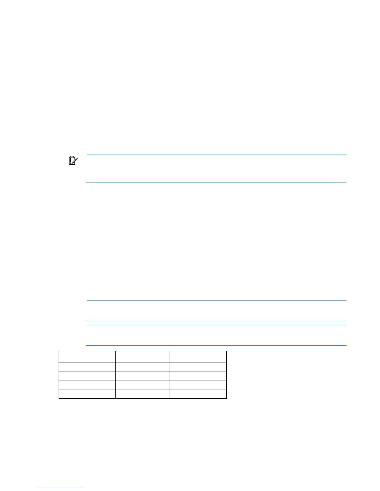
• Configuring memory options
1
RAID 0
• Language selection
For more information on RBSU, see the HP ROM-Based Setup Utility User Guide on the Documentation CD or
the HP website (http://www.hp.com/support/rbsu).
Using RBSU
To use RBSU, use the following keys:
• To access RBSU, press the F9 key during power-up when prompted.
• To navigate the menu system, use the arrow keys.
• To make selections, press the Enter key.
• To access Help for a highlighted configuration option, press the F1 key.
IMPORTANT: RBSU automatically saves settings when you press the Enter key. The utility does
not prompt you for confirmation of settings before you exit the utility. To change a selected setting,
Default configuration settings are applied to the server at one of the following times:
you must select a different setting and press the Enter key.
• Upon the first system power-up
• After defaults have been restored
Default configuration settings are sufficient for proper typical server operation, but configuration settings can
be modified using RBSU. The system will prompt you for access to RBSU with each power-up.
Auto-configuration process
The auto-configuration process automatically runs when you boot the server for the first time. During the
power-up sequence, the system ROM automatically configures the entire system without needing any
intervention. During this process, the ORCA utility, in most cases, automatically configures the array to a
default setting based on the number of drives connected to the server.
NOTE: If the boot drive is not empty or has been written to in the past, ORCA does not
Drives installed Drives used RAID level
1
2
3, 4, 5, or 6
More than 6
automatically configure the array. You must run ORCA to configure the array settings.
NOTE: The server may not support all the following examples.
2 RAID 1
3, 4, 5, or 6 RAID 5
0 None
To change any ORCA default settings and override the auto-configuration process, press the F8 key when
prompted.
For more information on RBSU, see the HP ROM-Based Setup Utility User Guide on the Documentation CD or
the HP website (http://www.hp.com/support/rbsu).
Software and configuration utilities 68
Page 69

Boot options
Near the end of the boot process, the boot options screen is displayed. This screen is visible for several
seconds before the system attempts to boot from a supported boot device. During this time, you can do the
following:
• Access RBSU by pressing the F9 key.
• Access Intelligent Provisioning Maintenance Menu by pressing the F10 key.
• Access the boot menu by pressing the F11 key.
• Force a PXE Network boot by pressing the F12 key.
Re-entering the server serial number and product ID
After you replace the system board, you must re-enter the server serial number and the product ID.
1. During the server startup sequence, press the F9 key to access RBSU.
2. Select the Advanced Options menu.
3. Select Service Options.
4. Select Serial Number. The following warning appears:
Warning: The serial number should ONLY be modified by qualified service
personnel. This value should always match the serial number located on the
chassis.
5. Press the Enter key to clear the warning.
6. Enter the serial number and press the Enter key.
7. Select Product ID. The following warning appears:
Warning: The Product ID should ONLY be modified by qualified service
personnel. This value should always match the Product ID located on the
chassis.
8. Enter the product ID and press the Enter key.
9. Press the Esc key to close the menu.
10. Press the Esc key to exit RBSU.
11. Press the F10 key to confirm exiting RBSU. The server automatically reboots.
Utilities and features
Array Configuration Utility
ACU is a utility with the following features:
• Runs as a local application or remote service accessed through the HP System Management Homepage
• Supports online array capacity expansion, logical drive extension, assignment of online spares, and
RAID or stripe size migration
• Suggests the optimum configuration for an unconfigured system
• For supported controllers, provides access to licensed features, including:
o Moving and deleting individual logical volumes
Software and configuration utilities 69
Page 70

o
Advanced Capacity Expansion (SATA to SAS and SAS to SATA)
o Offline Split Mirror
o RAID 6 and RAID 60
o RAID 1 (ADM) and RAID 10 (ADM)
o HP Drive Erase
o Video-On-Demand Advanced Controller Settings
• Provides different operating modes, enabling faster configuration or greater control over the
configuration options
• Remains available any time that the server is on
• Displays on-screen tips for individual steps of a configuration procedure
• Provides context-sensitive searchable help content
• Provides diagnostic and SmartSSD Wear Gauge functionality on the Diagnostics tab
ACU is now available as an embedded utility, starting with HP ProLiant Gen8 servers. To access ACU, use
one of the following methods:
• If an optional controller is not installed, press F10 during boot.
• If an optional controller is installed, when the system recognizes the controller during POST, press F5.
For optimum performance, the minimum display settings are 1024 × 768 resolution and 16-bit color. Servers
running Microsoft® operating systems require one of the following supported browsers:
• Internet Explorer 6.0 or later
• Mozilla Firefox 2.0 or later
For Linux servers, see the README.TXT file for additional browser and support information.
For more information about the controller and its features, see the HP Smart Array Controllers for HP ProLiant
Servers User Guide on the HP website (http://www.hp.com/support/SAC_UG_ProLiantServers_en). To
configure arrays, see the Configuring Arrays on HP Smart Array Controllers Reference Guide on the HP
website (http://www.hp.com/support/CASAC_RG_en).
Option ROM Configuration for Arrays
Before installing an operating system, you can use the ORCA utility to create the first logical drive, assign
RAID levels, and establish online spare configurations.
The utility also provides support for the following functions:
• Reconfiguring one or more logical drives
• Viewing the current logical drive configuration
• Deleting a logical drive configuration
• Setting the controller to be the boot controller
• Selecting the boot volume
If you do not use the utility, ORCA will default to the standard configuration.
For more information regarding the default configurations that ORCA uses, see the HP ROM-Based Setup
Utility User Guide on the Documentation CD or the HP website (http://www.hp.com/support/rbsu).
Software and configuration utilities 70
Page 71

For more information about the controller and its features, see the HP Smart Array Controllers for HP ProLiant
Servers User Guide on the HP website (http://www.hp.com/support/SAC_UG_ProLiantServers_en). To
configure arrays, see the Configuring Arrays on HP Smart Array Controllers Reference Guide on the HP
website (http://www.hp.com/support/CASAC_RG_en).
ROMPaq utility
The ROMPaq utility enables you to upgrade the system firmware (BIOS). To upgrade the firmware, insert a
ROMPaq USB Key into an available USB port and boot the system. In addition to ROMPaq, Online Flash
Components for Windows and Linux operating systems are available for updating the system firmware.
The ROMPaq utility checks the system and provides a choice (if more than one exists) of available firmware
revisions.
For more information, go to the HP website (http://www.hp.com/go/hpsc) and click on Drivers, Software
& Firmware. Then, enter your product name in the Find an HP product field and click Go.
Automatic Server Recovery
ASR is a feature that causes the system to restart when a catastrophic operating system error occurs, such as
a blue screen, ABEND (does not apply to HP ProLiant DL980 Servers), or panic. A system fail-safe timer, the
ASR timer, starts when the System Management driver, also known as the Health Driver, is loaded. When the
operating system is functioning properly, the system periodically resets the timer. However, when the
operating system fails, the timer expires and restarts the server.
ASR increases server availability by restarting the server within a specified time after a system hang. At the
same time, the HP SIM console notifies you by sending a message to a designated pager number that ASR
has restarted the system. You can disable ASR from the System Management Homepage or through RBSU.
USB support
HP provides both standard USB 2.0 support and legacy USB 2.0 support. Standard support is provided by
the OS through the appropriate USB device drivers. Before the OS loads, HP provides support for USB
devices through legacy USB support, which is enabled by default in the system ROM.
Legacy USB support provides USB functionality in environments where USB support is not available normally.
Specifically, HP provides legacy USB functionality for the following:
• POST
• RBSU
• Diagnostics
• DOS
• Operating environments which do not provide native USB support
Redundant ROM support
The server enables you to upgrade or configure the ROM safely with redundant ROM support. The server has
a single ROM that acts as two separate ROM images. In the standard implementation, one side of the ROM
contains the current ROM program version, while the other side of the ROM contains a backup version.
Software and configuration utilities 71
Page 72

NOTE: The server ships with the same version programmed on each side of the ROM.
Safety and security benefits
When you flash the system ROM, ROMPaq writes over the backup ROM and saves the current ROM as a
backup, enabling you to switch easily to the alternate ROM version if the new ROM becomes corrupted for
any reason. This feature protects the existing ROM version, even if you experience a power failure while
flashing the ROM.
Keeping the system current
Drivers
IMPORTANT: Always perform a backup before installing or updating device drivers.
The server includes new hardware that may not have driver support on all OS installation media.
If you are installing an Intelligent Provisioning-supported OS, use Intelligent Provisioning (on page 64) and its
Configure and Install feature to install the OS and latest supported drivers.
If you do not use Intelligent Provisioning to install an OS, drivers for some of the new hardware are required.
These drivers, as well as other option drivers, ROM images, and value-add software can be downloaded as
part of an SPP.
If you are installing drivers from SPP, be sure that you are using the latest SPP version that your server
supports. To verify that your server is using the latest supported version and for more information about SPP,
see the HP website (http://www.hp.com/go/spp/download).
To locate the drivers for a particular server, go to the HP website (http://www.hp.com/go/hpsc) and click
on Drivers, Software & Firmware. Then, enter your product name in the Find an HP product field and click
Go.
Software and firmware
Software and firmware should be updated before using the server for the first time, unless any installed
software or components require an older version. For system software and firmware updates, download the
SPP ("HP Service Pack for ProLiant" on page 67) from the HP website (http://www.hp.com/go/spp).
Version control
The VCRM and VCA are web-enabled Insight Management Agents tools that HP SIM uses to schedule
software update tasks to the entire enterprise.
• VCRM manages the repository for SPP. Administrators can view the SPP contents or configure VCRM to
automatically update the repository with internet downloads of the latest software and firmware from
HP.
• VCA compares installed software versions on the node with updates available in the VCRM managed
repository. Administrators configure VCA to point to a repository managed by VCRM.
Software and configuration utilities 72
Page 73

For more information about version control tools, see the HP Systems Insight Manager User Guide, the HP
Version Control Agent User Guide, and the HP Version Control Repository User Guide on the HP website
(http://www.hp.com/go/hpsim).
HP Operating Systems and Virtualization Software Support for
ProLiant Servers
For information about specific versions of a supported operating system, see the HP website
(http://www.hp.com/go/ossupport).
Change control and proactive notification
HP offers Change Control and Proactive Notification to notify customers 30 to 60 days in advance of
upcoming hardware and software changes on HP commercial products.
For more information, refer to the HP website (http://www.hp.com/go/pcn).
Software and configuration utilities 73
Page 74

Troubleshooting
Troubleshooting resources
The HP ProLiant Gen8 Troubleshooting Guide, Volume I: Troubleshooting provides procedures for resolving
common problems and comprehensive courses of action for fault isolation and identification, issue resolution,
and software maintenance on ProLiant servers and server blades. To view the guide, select a language:
• English (http://www.hp.com/support/ProLiant_TSG_v1_en)
• French (http://www.hp.com/support/ProLiant_TSG_v1_fr)
• Spanish (http://www.hp.com/support/ProLiant_TSG_v1_sp)
• German (http://www.hp.com/support/ProLiant_TSG_v1_gr)
• Japanese (http://www.hp.com/support/ProLiant_TSG_v1_jp)
• Simplified Chinese (http://www.hp.com/support/ProLiant_TSG_v1_sc)
The HP ProLiant Gen8 Troubleshooting Guide, Volume II: Error Messages provides a list of error messages
and information to assist with interpreting and resolving error messages on ProLiant servers and server
blades. To view the guide, select a language:
• English (http://www.hp.com/support/ProLiant_EMG_v1_en)
• French (http://www.hp.com/support/ProLiant_EMG_v1_fr)
• Spanish (http://www.hp.com/support/ProLiant_EMG_v1_sp)
• German (http://www.hp.com/support/ProLiant_EMG_v1_gr)
• Japanese (http://www.hp.com/support/ProLiant_EMG_v1_jp)
• Simplified Chinese (http://www.hp.com/support/ProLiant_EMG_v1_sc)
Troubleshooting 74
Page 75
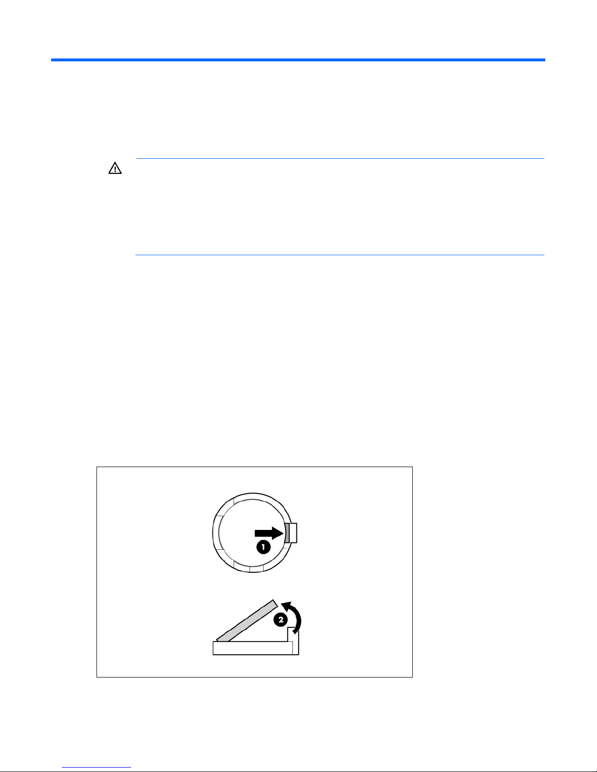
System battery replacement
If the server no longer automatically displays the correct date and time, you might have to replace the battery
that provides power to the real-time clock. Under normal use, battery life is 5 to 10 years.
WARNING: The computer contains an internal lithium manganese dioxide, a vanadium
pentoxide, or an alkaline battery pack. A risk of fire and burns exists if the battery pack is not
properly handled. To reduce the risk of personal injury:
• Do not attempt to recharge the battery.
• Do not expose the battery to temperatures higher than 60°C (140°F).
• Do not disassemble, crush, puncture, short external contacts, or dispose of in fire or water.
To remove the component:
1. Power down the server (on page 17).
2. Remove all power:
• Replace only with the spare designated for this product.
a. Disconnect each power cord from the power source.
b. Disconnect each power cord from the server.
3. Do one of the following:
o Extend the server from the rack (on page 17).
o Remove the server from the rack (on page 18).
4. Remove the access panel (on page 19).
5. Remove the air baffle (on page 20).
6. Locate the battery on the system board ("System board components" on page 10).
7. Remove the battery.
System battery replacement 75
Page 76

IMPORTANT: Replacing the system board battery resets the system ROM to its default
configuration. After replacing the battery, reconfigure the system through RBSU.
To replace the component, reverse the removal procedure.
For more information about battery replacement or proper disposal, contact an authorized reseller or an
authorized service provider.
System battery replacement 76
Page 77

Regulatory compliance notices
Regulatory compliance identification numbers
For the purpose of regulatory compliance certifications and identification, this product has been assigned a
unique regulatory model number. The regulatory model number can be found on the product nameplate
label, along with all required approval markings and information. When requesting compliance information
for this product, always refer to this regulatory model number. The regulatory model number is not the
Federal Communications Commission notice
marketing name or model number of the product.
Part 15 of the Federal Communications Commission (FCC) Rules and Regulations has established Radio
Frequency (RF) emission limits to provide an interference-free radio frequency spectrum. Many electronic
devices, including computers, generate RF energy incidental to their intended function and are, therefore,
covered by these rules. These rules place computers and related peripheral devices into two classes, A and
B, depending upon their intended installation. Class A devices are those that may reasonably be expected
to be installed in a business or commercial environment. Class B devices are those that may reasonably be
expected to be installed in a residential environment (for example, personal computers). The FCC requires
devices in both classes to bear a label indicating the interference potential of the device as well as additional
operating instructions for the user.
FCC rating label
The FCC rating label on the device shows the classification (A or B) of the equipment. Class B devices have
an FCC logo or ID on the label. Class A devices do not have an FCC logo or ID on the label. After you
determine the class of the device, refer to the corresponding statement.
FCC Notice, Class A Equipment
This equipment has been tested and found to comply with the limits for a Class A digital device, pursuant to
Part 15 of the FCC Rules. These limits are designed to provide reasonable protection against harmful
interference when the equipment is operated in a commercial environment. This equipment generates, uses,
and can radiate radio frequency energy and, if not installed and used in accordance with the instructions,
may cause harmful interference to radio communications. Operation of this equipment in a residential area
is likely to cause harmful interference, in which case the user will be required to correct the interference at
personal expense.
FCC Notice, Class B Equipment
This equipment has been tested and found to comply with the limits for a Class B digital device, pursuant to
Part 15 of the FCC Rules. These limits are designed to provide reasonable protection against harmful
interference in a residential installation. This equipment generates, uses, and can radiate radio frequency
energy and, if not installed and used in accordance with the instructions, may cause harmful interference to
Regulatory compliance notices 77
Page 78

radio communications. However, there is no guarantee that interference will not occur in a particular
installation. If this equipment does cause harmful interference to radio or television reception, which can be
determined by turning the equipment off and on, the user is encouraged to try to correct the interference by
one or more of the following measures:
• Reorient or relocate the receiving antenna.
• Increase the separation between the equipment and receiver.
• Connect the equipment into an outlet on a circuit that is different from that to which the receiver is
connected.
• Consult the dealer or an experienced radio or television technician for help.
Declaration of conformity for products marked with
the FCC logo, United States only
This device complies with Part 15 of the FCC Rules. Operation is subject to the following two conditions: (1)
this device may not cause harmful interference, and (2) this device must accept any interference received,
including interference that may cause undesired operation.
For questions regarding this product, contact us by mail or telephone:
• Hewlett-Packard Company
P. O. Box 692000, Mail Stop 530113
Houston, Texas 77269-2000
• 1-800-HP-INVENT (1-800-474-6836). (For continuous quality improvement, calls may be recorded or
monitored.)
For questions regarding this FCC declaration, contact us by mail or telephone:
• Hewlett-Packard Company
P. O. Box 692000, Mail Stop 510101
Houston, Texas 77269-2000
• 1281-514-3333
To identify this product, refer to the part, series, or model number found on the product.
Modifications
The FCC requires the user to be notified that any changes or modifications made to this device that are not
expressly approved by Hewlett-Packard Company may void the user’s authority to operate the equipment.
Cables
Connections to this device must be made with shielded cables with metallic RFI/EMI connector hoods in
order to maintain compliance with FCC Rules and Regulations.
Canadian notice (Avis Canadien)
Class A equipment
Regulatory compliance notices 78
Page 79

This Class A digital apparatus meets all requirements of the Canadian Interference-Causing Equipment
Regulations.
Cet appareil numérique de la classe A respecte toutes les exigences du Règlement sur le matériel brouilleur
du Canada.
Class B equipment
This Class B digital apparatus meets all requirements of the Canadian Interference-Causing Equipment
Regulations.
Cet appareil numérique de la classe B respecte toutes les exigences du Règlement sur le matériel brouilleur
du Canada.
European Union regulatory notice
Products bearing the CE marking comply with the following EU Directives:
• Low Voltage Directive 2006/95/EC
• EMC Directive 2004/108/EC
• Ecodesign Directive 2009/125/EC, where applicable
CE compliance of this product is valid if powered with the correct CE-marked AC adapter provided by HP.
Compliance with these directives implies conformity to applicable harmonized European standards
(European Norms) that are listed in the EU Declaration of Conformity issued by HP for this product or product
family and available (in English only) either within the product documentation or at the following HP website
(http://www.hp.eu/certificates) (type the product number in the search field).
The compliance is indicated by one of the following conformity markings placed on the product:
For non-telecommunications products and for EU harmonized telecommunications products, such as
Bluetooth® within power class below 10mW.
For EU non-harmonized telecommunications products (If applicable, a 4-digit notified body number is
inserted between CE and !).
Please refer to the regulatory label provided on the product.
The point of contact for regulatory matters is Hewlett-Packard GmbH, Dept./MS: HQ-TRE, Herrenberger
Strasse 140, 71034 Boeblingen, GERMANY.
Disposal of waste equipment by users in private
households in the European Union
Regulatory compliance notices 79
Page 80
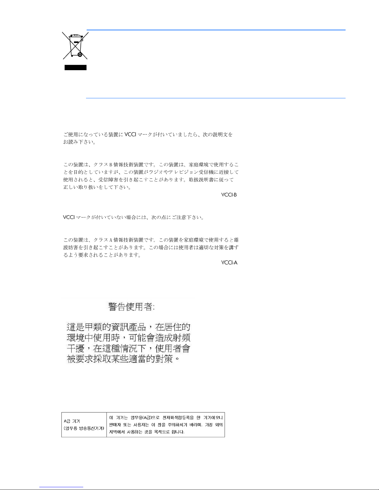
This symbol on the product or on its packaging indicates that this product must not be disposed of
time of disposal will help to conserve natural resources and ensure that it is recycled in a manner
with your other household waste. Instead, it is your responsibility to dispose of your waste
equipment by handing it over to a designated collection point for the recycling of waste electrical
and electronic equipment. The separate collection and recycling of your waste equipment at the
that protects human health and the environment. For more information about where you can drop
off your waste equipment for recycling, please contact your local city office, your household
waste disposal service or the shop where you purchased the product.
Japanese notice
BSMI notice
Korean notice
Class A equipment
Regulatory compliance notices 80
Page 81
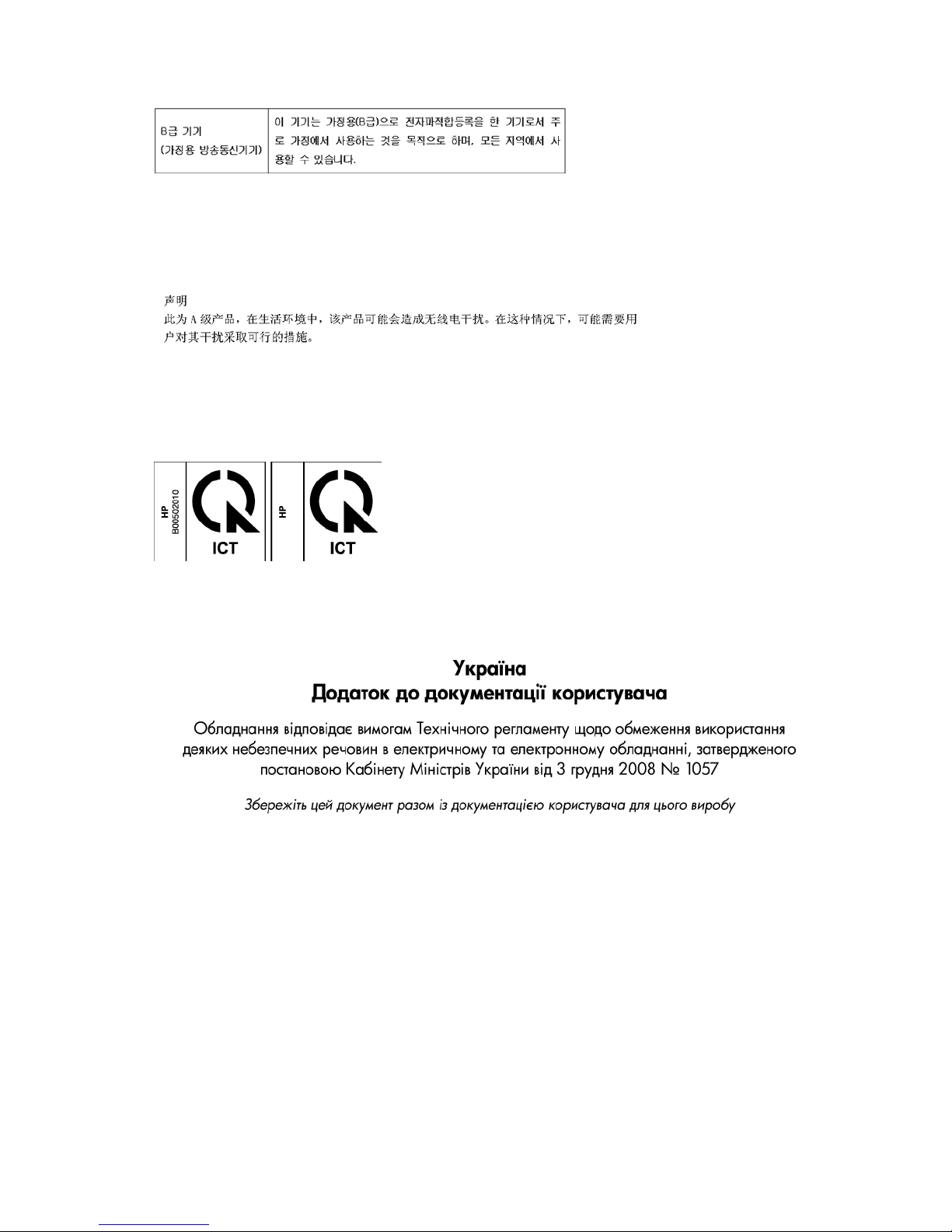
Class B equipment
Chinese notice
Class A equipment
Vietnam compliance marking notice
This marking is for applicable products only.
Ukraine notice
Laser compliance
This product may be provided with an optical storage device (that is, CD or DVD drive) and/or fiber optic
transceiver. Each of these devices contains a laser that is classified as a Class 1 Laser Product in accordance
with US FDA regulations and the IEC 60825-1. The product does not emit hazardous laser radiation.
Each laser product complies with 21 CFR 1040.10 and 1040.11 except for deviations pursuant to Laser
Notice No. 50, dated June 24, 2007; and with IEC 60825-1:2007.
Regulatory compliance notices 81
Page 82
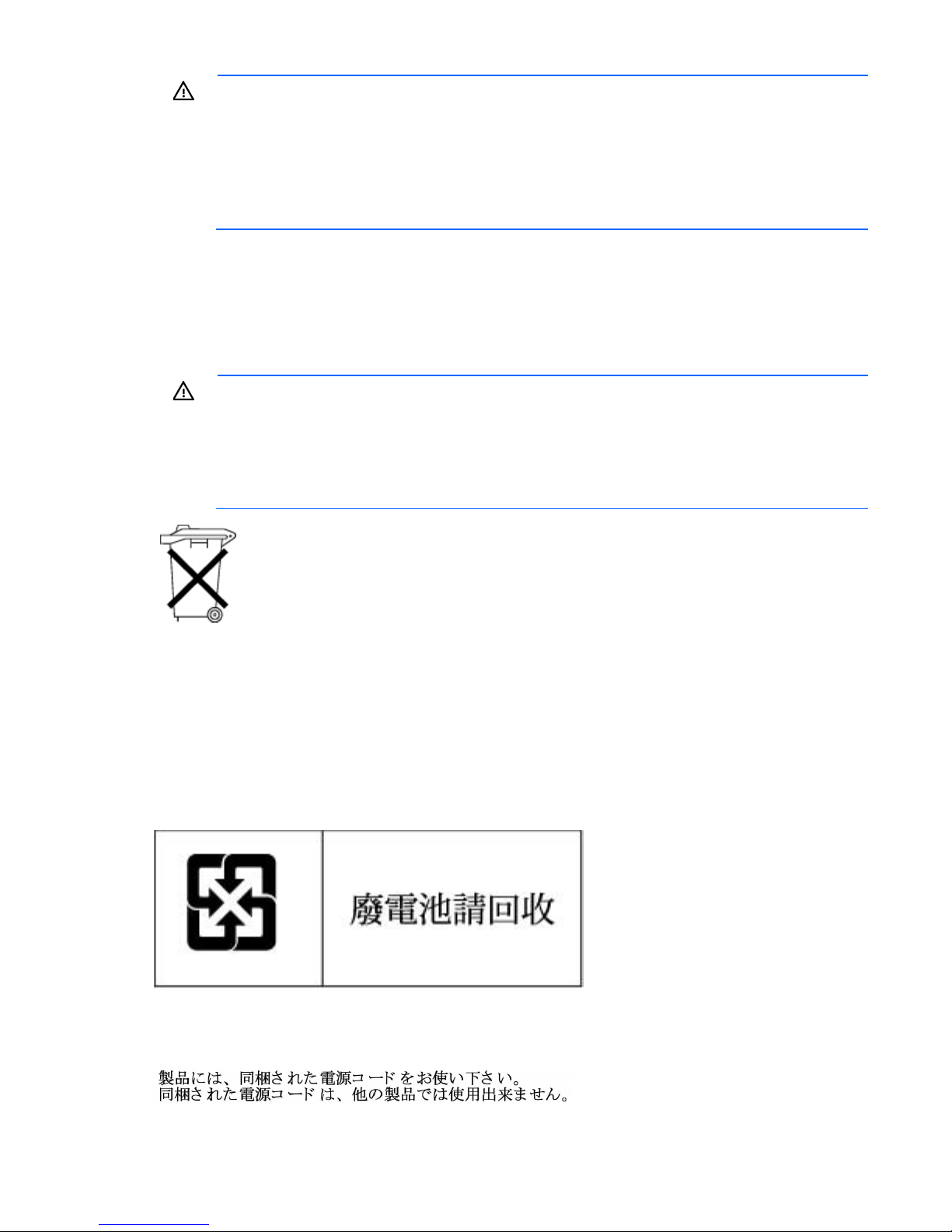
WARNING: Use of controls or adjustments or performance of procedures other than those
specified herein or in the laser product's installation guide may result in hazardous radiation
exposure. To reduce the risk of exposure to hazardous radiation:
• Do not try to open the module enclosure. There are no user-serviceable components inside.
• Do not operate controls, make adjustments, or perform procedures to the laser device other
than those specified herein.
• Allow only HP Authorized Service technicians to repair the unit.
The Center for Devices and Radiological Health (CDRH) of the U.S. Food and Drug Administration
implemented regulations for laser products on August 2, 1976. These regulations apply to laser products
manufactured from August 1, 1976. Compliance is mandatory for products marketed in the United States.
Battery replacement notice
WARNING: The computer contains an internal lithium manganese dioxide, a vanadium
pentoxide, or an alkaline battery pack. A risk of fire and burns exists if the battery pack is not
properly handled. To reduce the risk of personal injury:
• Do not attempt to recharge the battery.
• Do not expose the battery to temperatures higher than 60°C (140°F).
• Do not disassemble, crush, puncture, short external contacts, or dispose of in fire or water.
Batteries, battery packs, and accumulators should not be disposed of together with the general
household waste. To forward them to recycling or proper disposal, use the public collection system or
return them to HP, an authorized HP Partner, or their agents.
For more information about battery replacement or proper disposal, contact an authorized reseller or an
authorized service provider.
Taiwan battery recycling notice
The Taiwan EPA requires dry battery manufacturing or importing firms in accordance with Article 15 of the
Waste Disposal Act to indicate the recovery marks on the batteries used in sales, giveaway or promotion.
Contact a qualified Taiwanese recycler for proper battery disposal.
Power cord statement for Japan
Regulatory compliance notices 82
Page 83

Acoustics statement for Germany (Geräuschemission)
Schalldruckpegel LpA < 70 dB(A)
Zuschauerpositionen (bystander positions), Normaler Betrieb (normal operation)
Nach ISO 7779:1999 (Typprüfung)
Regulatory compliance notices 83
Page 84

Electrostatic discharge
Preventing electrostatic discharge
To prevent damaging the system, be aware of the precautions you need to follow when setting up the system
or handling parts. A discharge of static electricity from a finger or other conductor may damage system
boards or other static-sensitive devices. This type of damage may reduce the life expectancy of the device.
To prevent electrostatic damage:
• Avoid hand contact by transporting and storing products in static-safe containers.
• Keep electrostatic-sensitive parts in their containers until they arrive at static-free workstations.
• Place parts on a grounded surface before removing them from their containers.
• Avoid touching pins, leads, or circuitry.
• Always be properly grounded when touching a static-sensitive component or assembly.
Grounding methods to prevent electrostatic discharge
Several methods are used for grounding. Use one or more of the following methods when handling or
installing electrostatic-sensitive parts:
• Use a wrist strap connected by a ground cord to a grounded workstation or computer chassis. Wrist
straps are flexible straps with a minimum of 1 megohm ±10 percent resistance in the ground cords. To
provide proper ground, wear the strap snug against the skin.
• Use heel straps, toe straps, or boot straps at standing workstations. Wear the straps on both feet when
standing on conductive floors or dissipating floor mats.
• Use conductive field service tools.
• Use a portable field service kit with a folding static-dissipating work mat.
If you do not have any of the suggested equipment for proper grounding, have an authorized reseller install
the part.
For more information on static electricity or assistance with product installation, contact an authorized
reseller.
Electrostatic discharge 84
Page 85
Specifications
10°C to 35°C (50°F to 95°F)
5% to 95%
69.90 cm (27.50 in)
Environmental specifications
Specification Value
Temperature range*
Operating
Nonoperating
Relative humidity
(noncondensing)
Operating, maximum wet bulb
temperature of 28°C (82.4°F)
Nonoperating, maximum wet
bulb temperature of 38.7°C
(101.7°F)
* All temperature ratings shown are for sea level. An altitude derating of 1°C per 304.8 m (1.8°F per 1,000 ft) to 3048
m (10,000 ft) is applicable. No direct sunlight allowed.
-30°C to 60°C (-22°F to 140°F)
10% to 90%
Server specifications
Specification Value
Height
Depth for models with LFF drive cage
Depth for models with SFF drive cage
Width
Weight (approximate range)
4.32 cm (1.70 in)
75.00 cm (29.50 in)
43.46 cm (17.11 in)
10.00 kg to 24.00 kg (22.00 lb to 53.00 lb)
Power supply specifications
Depending on installed options, the server is configured with one of the following power supplies:
• HP 350 W 1U Factory Integrated Power Supply
• HP 460 W CS Gold Hot-plug Power Supply (92% efficiency)
HP 350 W 1U Factory Integrated Power Supply
• HP 460 W CS Platinum Plus Hot-plug Power Supply (94% efficiency)
Specification Value
Input requirements
Rated input voltage
Rated input frequency
—
100 V AC–240 V AC
50 Hz–60 Hz
Specifications 85
Page 86
6 A
—
526 W at 100 V AC
Rated input current
Rated input power
430 W at 115 V
430 W at 230 V
Power supply output
Efficiency
Not less than 82% at 100% load
Not less than 85% at 50% load
Not less than 82% at 20% load
Maximum peak power
400 W at 100 V to 120 V AC
input
400 W at 200 V to 240 V AC
input
HP 460 W CS Gold Hot-plug Power Supply (92% efficiency)
Specification Value
Input requirements
Rated input voltage
Rated input frequency
Rated input current
Rated input power
Power supply output
Efficiency
Rated steady-state output power
Maximum peak power
—
100 V AC–240 V AC
50 Hz–60 Hz
6 A–3 A
505 W at 200 V AC
—
Not less than 87.5% at 100% load
Not less than 89.5% at 50% load
Not less than 87.5% at 20% load
460 W at 100 V to 120 V AC
output
460 W at 200 V to 240 V AC
output
460 W at 100 V to 120 V AC
output
460 W at 200 V to 240 V AC
output
HP 460 W CS Platinum Plus Hot-plug Power Supply (94%
efficiency)
Specification Value
Input requirements
Rated input voltage
Rated input frequency
Rated input current
Rated input power
Power supply output
Efficiency
—
100 V AC–240 V AC
50 Hz–60 Hz
6 A–3 A
509 W at 100 V AC
495 W at 230 V AC
—
Not less than 89% at 100% load
Not less than 92% at 50% load
Not less than 90% at 20% load
Specifications 86
Page 87

460 W at 100 V to 120 V AC
Rated steady-state output power
output
460 W at 200 V to 240 V AC
output
Maximum peak power
460 W at 100 V to 120 V AC
output
460 W at 200 V to 240 V AC
output
Hot-plug power supply calculations
For hot-plug power supply specifications and calculators to determine electrical and heat loading for the
server, refer to the HP Enterprise Configurator website (http://h30099.www3.hp.com/configurator/).
Specifications 87
Page 88

Support and other resources
Before you contact HP
Be sure to have the following information available before you call HP:
• Active Health System log
Download and have available an Active Health System log for 3 days before the failure was detected.
For more information, see the HP iLO 4 User Guide or HP Intelligent Provisioning User Guide on the HP
website (http://www.hp.com/go/ilo/docs).
• Onboard Administrator SHOW ALL report (for HP BladeSystem products only)
For more information on obtaining the Onboard Administrator SHOW ALL report, see the HP website
(http://h20000.www2.hp.com/bizsupport/TechSupport/Document.jsp?lang=en&cc=us&objectID=c
02843807).
• Technical support registration number (if applicable)
• Product serial number
• Product model name and number
• Product identification number
• Applicable error messages
• Add-on boards or hardware
• Third-party hardware or software
• Operating system type and revision level
HP contact information
For United States and worldwide contact information, see the Contact HP website
(http://www.hp.com/go/assistance).
In the United States:
• To contact HP by phone, call 1-800-334-5144. For continuous quality improvement, calls may be
recorded or monitored.
• If you have purchased a Care Pack (service upgrade), see the Support & Drivers website
(http://www8.hp.com/us/en/support-drivers.html). If the problem cannot be resolved at the website,
call 1-800-633-3600. For more information about Care Packs, see the HP website
(http://pro-aq-sama.houston.hp.com/services/cache/10950-0-0-225-121.html).
Customer Self Repair
HP products are designed with many Customer Self Repair (CSR) parts to minimize repair time and allow for
greater flexibility in performing defective parts replacement. If during the diagnosis period HP (or HP service
Support and other resources 88
Page 89

providers or service partners) identifies that the repair can be accomplished by the use of a CSR part, HP will
ship that part directly to you for replacement. There are two categories of CSR parts:
• Mandatory—Parts for which customer self repair is mandatory. If you request HP to replace these parts,
you will be charged for the travel and labor costs of this service.
• Optional—Parts for which customer self repair is optional. These parts are also designed for customer
self repair. If, however, you require that HP replace them for you, there may or may not be additional
charges, depending on the type of warranty service designated for your product.
NOTE: Some HP parts are not designed for customer self repair. In order to satisfy the customer warranty,
HP requires that an authorized service provider replace the part. These parts are identified as "No" in the
Illustrated Parts Catalog.
Based on availability and where geography permits, CSR parts will be shipped for next business day
delivery. Same day or four-hour delivery may be offered at an additional charge where geography permits.
If assistance is required, you can call the HP Technical Support Center and a technician will help you over the
telephone. HP specifies in the materials shipped with a replacement CSR part whether a defective part must
be returned to HP. In cases where it is required to return the defective part to HP, you must ship the defective
part back to HP within a defined period of time, normally five (5) business days. The defective part must be
returned with the associated documentation in the provided shipping material. Failure to return the defective
part may result in HP billing you for the replacement. With a customer self repair, HP will pay all shipping
and part return costs and determine the courier/carrier to be used.
For more information about HP's Customer Self Repair program, contact your local service provider. For the
North American program, refer to the HP website (http://www.hp.com/go/selfrepair).
Réparation par le client (CSR)
Les produits HP comportent de nombreuses pièces CSR (Customer Self Repair = réparation par le client) afin
de minimiser les délais de réparation et faciliter le remplacement des pièces défectueuses. Si pendant la
période de diagnostic, HP (ou ses partenaires ou mainteneurs agréés) détermine que la réparation peut être
effectuée à l'aide d'une pièce CSR, HP vous l'envoie directement. Il existe deux catégories de pièces CSR:
Obligatoire - Pièces pour lesquelles la réparation par le client est obligatoire. Si vous demandez à HP de
remplacer ces pièces, les coûts de déplacement et main d'œuvre du service vous seront facturés.
Facultatif - Pièces pour lesquelles la réparation par le client est facultative. Ces pièces sont également
conçues pour permettre au client d'effectuer lui-même la réparation. Toutefois, si vous demandez à HP de
remplacer ces pièces, l'intervention peut ou non vous être facturée, selon le type de garantie applicable à
votre produit.
REMARQUE: Certaines pièces HP ne sont pas conçues pour permettre au client d'effectuer lui-même la
réparation. Pour que la garantie puisse s'appliquer, HP exige que le remplacement de la pièce soit effectué
par un Mainteneur Agréé. Ces pièces sont identifiées par la mention "Non" dans le Catalogue illustré.
Les pièces CSR sont livrées le jour ouvré suivant, dans la limite des stocks disponibles et selon votre situation
géographique. Si votre situation géographique le permet et que vous demandez une livraison le jour même
ou dans les 4 heures, celle-ci vous sera facturée. Pour bénéficier d'une assistance téléphonique, appelez le
Centre d'assistance technique HP. Dans les documents envoyés avec la pièce de rechange CSR, HP précise
s'il est nécessaire de lui retourner la pièce défectueuse. Si c'est le cas, vous devez le faire dans le délai
indiqué, généralement cinq (5) jours ouvrés. La pièce et sa documentation doivent être retournées dans
l'emballage fourni. Si vous ne retournez pas la pièce défectueuse, HP se réserve le droit de vous facturer les
coûts de remplacement. Dans le cas d'une pièce CSR, HP supporte l'ensemble des frais d'expédition et de
retour, et détermine la société de courses ou le transporteur à utiliser.
Support and other resources 89
Page 90

Pour plus d'informations sur le programme CSR de HP, contactez votre Mainteneur Agrée local. Pour plus
d'informations sur ce programme en Amérique du Nord, consultez le site Web HP
(http://www.hp.com/go/selfrepair).
Riparazione da parte del cliente
Per abbreviare i tempi di riparazione e garantire una maggiore flessibilità nella sostituzione di parti
difettose, i prodotti HP sono realizzati con numerosi componenti che possono essere riparati direttamente
dal cliente (CSR, Customer Self Repair). Se in fase di diagnostica HP (o un centro di servizi o di assistenza
HP) identifica il guasto come riparabile mediante un ricambio CSR, HP lo spedirà direttamente al cliente per
la sostituzione. Vi sono due categorie di parti CSR:
Obbligatorie – Parti che devono essere necessariamente riparate dal cliente. Se il cliente ne affida la
riparazione ad HP, deve sostenere le spese di spedizione e di manodopera per il servizio.
Opzionali – Parti la cui riparazione da parte del cliente è facoltativa. Si tratta comunque di componenti
progettati per questo scopo. Se tuttavia il cliente ne richiede la sostituzione ad HP, potrebbe dover sostenere
spese addizionali a seconda del tipo di garanzia previsto per il prodotto.
NOTA: alcuni componenti HP non sono progettati per la riparazione da parte del cliente. Per rispettare la
garanzia, HP richiede che queste parti siano sostituite da un centro di assistenza autorizzato. Tali parti sono
identificate da un "No" nel Catalogo illustrato dei componenti.
In base alla disponibilità e alla località geografica, le parti CSR vengono spedite con consegna entro il
giorno lavorativo seguente. La consegna nel giorno stesso o entro quattro ore è offerta con un supplemento
di costo solo in alcune zone. In caso di necessità si può richiedere l'assistenza telefonica di un addetto del
centro di supporto tecnico HP. Nel materiale fornito con una parte di ricambio CSR, HP specifica se il cliente
deve restituire dei componenti. Qualora sia richiesta la resa ad HP del componente difettoso, lo si deve
spedire ad HP entro un determinato periodo di tempo, generalmente cinque (5) giorni lavorativi. Il
componente difettoso deve essere restituito con la documentazione associata nell'imballo di spedizione
fornito. La mancata restituzione del componente può comportare la fatturazione del ricambio da parte di HP.
Nel caso di riparazione da parte del cliente, HP sostiene tutte le spese di spedizione e resa e sceglie il
corriere/vettore da utilizzare.
Per ulteriori informazioni sul programma CSR di HP contattare il centro di assistenza di zona. Per il
programma in Nord America fare riferimento al sito Web HP (http://www.hp.com/go/selfrepair).
Customer Self Repair
HP Produkte enthalten viele CSR-Teile (Customer Self Repair), um Reparaturzeiten zu minimieren und höhere
Flexibilität beim Austausch defekter Bauteile zu ermöglichen. Wenn HP (oder ein HP Servicepartner) bei der
Diagnose feststellt, dass das Produkt mithilfe eines CSR-Teils repariert werden kann, sendet Ihnen HP dieses
Bauteil zum Austausch direkt zu. CSR-Teile werden in zwei Kategorien unterteilt:
Zwingend – Teile, für die das Customer Self Repair-Verfahren zwingend vorgegeben ist. Wenn Sie den
Austausch dieser Teile von HP vornehmen lassen, werden Ihnen die Anfahrt- und Arbeitskosten für diesen
Service berechnet.
Optional – Teile, für die das Customer Self Repair-Verfahren optional ist. Diese Teile sind auch für Customer
Self Repair ausgelegt. Wenn Sie jedoch den Austausch dieser Teile von HP vornehmen lassen möchten,
können bei diesem Service je nach den für Ihr Produkt vorgesehenen Garantiebedingungen zusätzliche
Kosten anfallen.
Support and other resources 90
Page 91

HINWEIS: Einige Teile sind nicht für Customer Self Repair ausgelegt. Um den Garantieanspruch des
Kunden zu erfüllen, muss das Teil von einem HP Servicepartner ersetzt werden. Im illustrierten Teilekatalog
sind diese Teile mit „No“ bzw. „Nein“ gekennzeichnet.
CSR-Teile werden abhängig von der Verfügbarkeit und vom Lieferziel am folgenden Geschäftstag geliefert.
Für bestimmte Standorte ist eine Lieferung am selben Tag oder innerhalb von vier Stunden gegen einen
Aufpreis verfügbar. Wenn Sie Hilfe benötigen, können Sie das HP technische Support Center anrufen und
sich von einem Mitarbeiter per Telefon helfen lassen. Den Materialien, die mit einem CSR-Ersatzteil geliefert
werden, können Sie entnehmen, ob das defekte Teil an HP zurückgeschickt werden muss. Wenn es
erforderlich ist, das defekte Teil an HP zurückzuschicken, müssen Sie dies innerhalb eines vorgegebenen
Zeitraums tun, in der Regel innerhalb von fünf (5) Geschäftstagen. Das defekte Teil muss mit der zugehörigen
Dokumentation in der Verpackung zurückgeschickt werden, die im Lieferumfang enthalten ist. Wenn Sie das
defekte Teil nicht zurückschicken, kann HP Ihnen das Ersatzteil in Rechnung stellen. Im Falle von Customer
Self Repair kommt HP für alle Kosten für die Lieferung und Rücksendung auf und bestimmt den
Kurier-/Frachtdienst.
Weitere Informationen über das HP Customer Self Repair Programm erhalten Sie von Ihrem Servicepartner
vor Ort. Informationen über das CSR-Programm in Nordamerika finden Sie auf der HP Website unter
(http://www.hp.com/go/selfrepair).
Reparaciones del propio cliente
Los productos de HP incluyen muchos componentes que el propio usuario puede reemplazar (Customer Self
Repair, CSR) para minimizar el tiempo de reparación y ofrecer una mayor flexibilidad a la hora de realizar
sustituciones de componentes defectuosos. Si, durante la fase de diagnóstico, HP (o los proveedores o socios
de servicio de HP) identifica que una reparación puede llevarse a cabo mediante el uso de un componente
CSR, HP le enviará dicho componente directamente para que realice su sustitución. Los componentes CSR se
clasifican en dos categorías:
• Obligatorio: componentes para los que la reparación por parte del usuario es obligatoria. Si solicita a
HP que realice la sustitución de estos componentes, tendrá que hacerse cargo de los gastos de
desplazamiento y de mano de obra de dicho servicio.
• Opcional: componentes para los que la reparación por parte del usuario es opcional. Estos
componentes también están diseñados para que puedan ser reparados por el usuario. Sin embargo, si
precisa que HP realice su sustitución, puede o no conllevar costes adicionales, dependiendo del tipo de
servicio de garantía correspondiente al producto.
NOTA: Algunos componentes no están diseñados para que puedan ser reparados por el usuario. Para que
el usuario haga valer su garantía, HP pone como condición que un proveedor de servicios autorizado
realice la sustitución de estos componentes. Dichos componentes se identifican con la palabra "No" en el
catálogo ilustrado de componentes.
Según la disponibilidad y la situación geográfica, los componentes CSR se enviarán para que lleguen a su
destino al siguiente día laborable. Si la situación geográfica lo permite, se puede solicitar la entrega en el
mismo día o en cuatro horas con un coste adicional. Si precisa asistencia técnica, puede llamar al Centro de
asistencia técnica de HP y recibirá ayuda telefónica por parte de un técnico. Con el envío de materiales
para la sustitución de componentes CSR, HP especificará si los componentes defectuosos deberán
devolverse a HP. En aquellos casos en los que sea necesario devolver algún componente a HP, deberá
hacerlo en el periodo de tiempo especificado, normalmente cinco días laborables. Los componentes
defectuosos deberán devolverse con toda la documentación relacionada y con el embalaje de envío. Si no
enviara el componente defectuoso requerido, HP podrá cobrarle por el de sustitución. En el caso de todas
Support and other resources 91
Page 92

sustituciones que lleve a cabo el cliente, HP se hará cargo de todos los gastos de envío y devolución de
componentes y escogerá la empresa de transporte que se utilice para dicho servicio.
Para obtener más información acerca del programa de Reparaciones del propio cliente de HP, póngase en
contacto con su proveedor de servicios local. Si está interesado en el programa para Norteamérica, visite
la página web de HP siguiente (http://www.hp.com/go/selfrepair).
Customer Self Repair
Veel onderdelen in HP producten zijn door de klant zelf te repareren, waardoor de reparatieduur tot een
minimum beperkt kan blijven en de flexibiliteit in het vervangen van defecte onderdelen groter is. Deze
onderdelen worden CSR-onderdelen (Customer Self Repair) genoemd. Als HP (of een HP Service Partner) bij
de diagnose vaststelt dat de reparatie kan worden uitgevoerd met een CSR-onderdeel, verzendt HP dat
onderdeel rechtstreeks naar u, zodat u het defecte onderdeel daarmee kunt vervangen. Er zijn twee
categorieën CSR-onderdelen:
Verplicht: Onderdelen waarvoor reparatie door de klant verplicht is. Als u HP verzoekt deze onderdelen
voor u te vervangen, worden u voor deze service reiskosten en arbeidsloon in rekening gebracht.
Optioneel: Onderdelen waarvoor reparatie door de klant optioneel is. Ook deze onderdelen zijn ontworpen
voor reparatie door de klant. Als u echter HP verzoekt deze onderdelen voor u te vervangen, kunnen
daarvoor extra kosten in rekening worden gebracht, afhankelijk van het type garantieservice voor het
product.
OPMERKING: Sommige HP onderdelen zijn niet ontwikkeld voor reparatie door de klant. In verband met
de garantievoorwaarden moet het onderdeel door een geautoriseerde Service Partner worden vervangen.
Deze onderdelen worden in de geïllustreerde onderdelencatalogus aangemerkt met "Nee".
Afhankelijk van de leverbaarheid en de locatie worden CSR-onderdelen verzonden voor levering op de
eerstvolgende werkdag. Levering op dezelfde dag of binnen vier uur kan tegen meerkosten worden
aangeboden, indien dit mogelijk is gezien de locatie. Indien assistentie gewenst is, belt u een HP Service
Partner om via de telefoon technische ondersteuning te ontvangen. HP vermeldt in de documentatie bij het
vervangende CSR-onderdeel of het defecte onderdeel aan HP moet worden geretourneerd. Als het defecte
onderdeel aan HP moet worden teruggezonden, moet u het defecte onderdeel binnen een bepaalde
periode, gewoonlijk vijf (5) werkdagen, retourneren aan HP. Het defecte onderdeel moet met de
bijbehorende documentatie worden geretourneerd in het meegeleverde verpakkingsmateriaal. Als u het
defecte onderdeel niet terugzendt, kan HP u voor het vervangende onderdeel kosten in rekening brengen. Bij
reparatie door de klant betaalt HP alle verzendkosten voor het vervangende en geretourneerde onderdeel en
kiest HP zelf welke koerier/transportonderneming hiervoor wordt gebruikt.
Neem contact op met een Service Partner voor meer informatie over het Customer Self Repair programma
van HP. Informatie over Service Partners vindt u op de HP website (http://www.hp.com/go/selfrepair).
Reparo feito pelo cliente
Os produtos da HP são projetados com muitas peças para reparo feito pelo cliente (CSR) de modo a
minimizar o tempo de reparo e permitir maior flexibilidade na substituição de peças com defeito. Se,
durante o período de diagnóstico, a HP (ou fornecedores/parceiros de serviço da HP) concluir que o reparo
pode ser efetuado pelo uso de uma peça CSR, a peça de reposição será enviada diretamente ao cliente.
Existem duas categorias de peças CSR:
Obrigatória – Peças cujo reparo feito pelo cliente é obrigatório. Se desejar que a HP substitua essas peças,
serão cobradas as despesas de transporte e mão-de-obra do serviço.
Support and other resources 92
Page 93
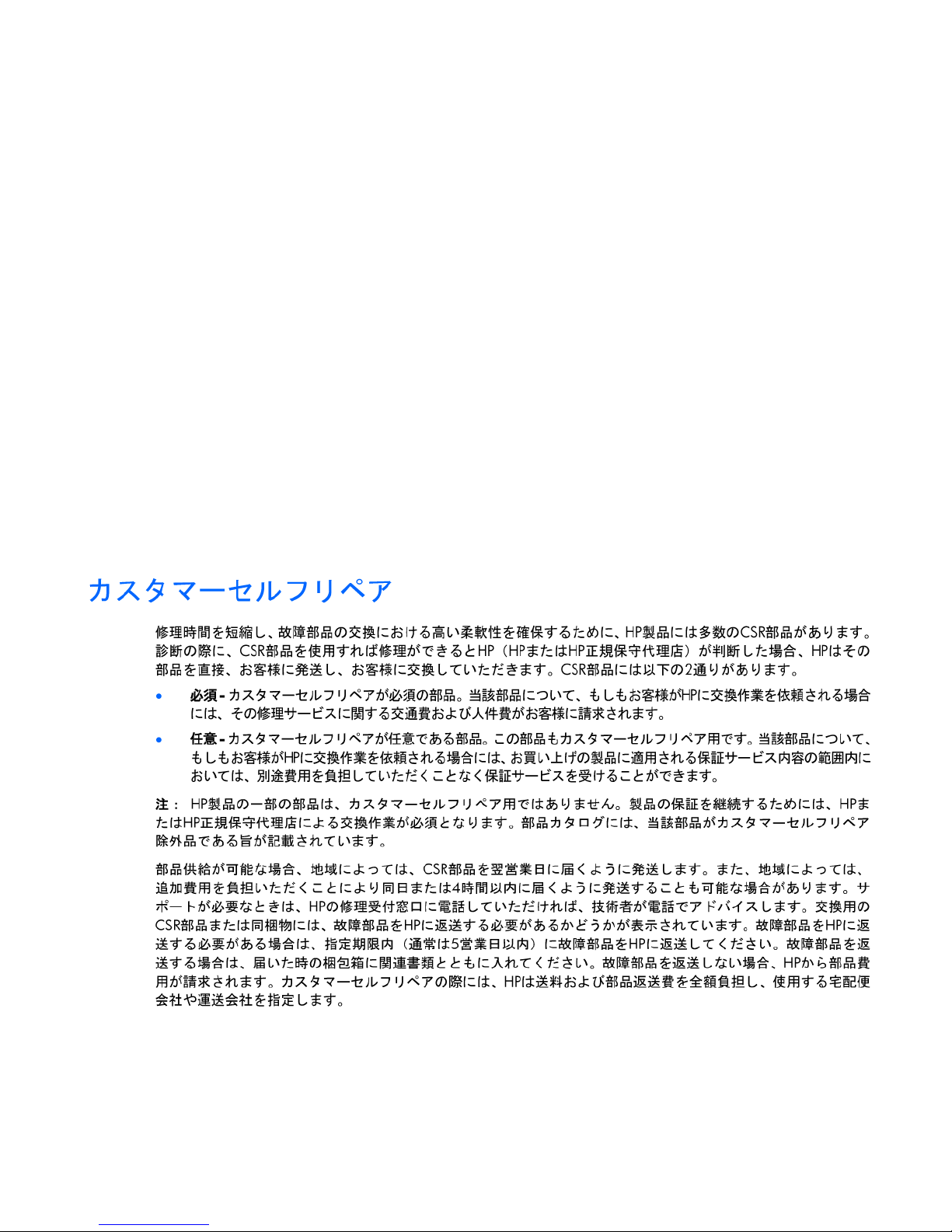
Opcional – Peças cujo reparo feito pelo cliente é opcional. Essas peças também são projetadas para o
reparo feito pelo cliente. No entanto, se desejar que a HP as substitua, pode haver ou não a cobrança de
taxa adicional, dependendo do tipo de serviço de garantia destinado ao produto.
OBSERVAÇÃO: Algumas peças da HP não são projetadas para o reparo feito pelo cliente. A fim de
cumprir a garantia do cliente, a HP exige que um técnico autorizado substitua a peça. Essas peças estão
identificadas com a marca "No" (Não), no catálogo de peças ilustrado.
Conforme a disponibilidade e o local geográfico, as peças CSR serão enviadas no primeiro dia útil após o
pedido. Onde as condições geográficas permitirem, a entrega no mesmo dia ou em quatro horas pode ser
feita mediante uma taxa adicional. Se precisar de auxílio, entre em contato com o Centro de suporte técnico
da HP para que um técnico o ajude por telefone. A HP especifica nos materiais fornecidos com a peça CSR
de reposição se a peça com defeito deve ser devolvida à HP. Nos casos em que isso for necessário, é
preciso enviar a peça com defeito à HP dentro do período determinado, normalmente cinco (5) dias úteis.
A peça com defeito deve ser enviada com a documentação correspondente no material de transporte
fornecido. Caso não o faça, a HP poderá cobrar a reposição. Para as peças de reparo feito pelo cliente, a
HP paga todas as despesas de transporte e de devolução da peça e determina a transportadora/serviço
postal a ser utilizado.
Para obter mais informações sobre o programa de reparo feito pelo cliente da HP, entre em contato com o
fornecedor de serviços local. Para o programa norte-americano, visite o site da HP
(http://www.hp.com/go/selfrepair).
Support and other resources 93
Page 94
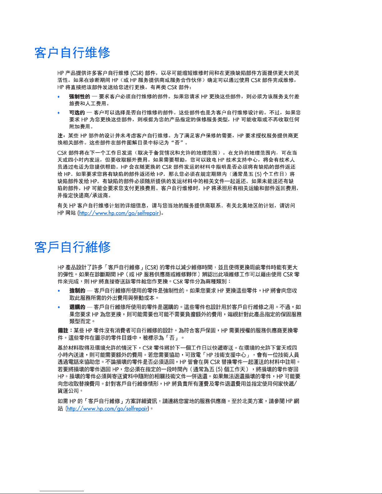
Support and other resources 94
Page 95
Support and other resources 95
Page 96

Acronyms and abbreviations
ABEND
abnormal end
ACU
Array Configuration Utility
AMP
Advanced Memory Protection
ASR
Automatic Server Recovery
BMC
baseboard management controller
BSMI
Bureau of Standards, Metrology and Inspection
CE
Conformité Européenne (European Conformity)
CSA
Canadian Standards Association
CSR
Customer Self Repair
DDR
double data rate
EMI
electromagnetic interference
FBWC
flash-backed write cache
Acronyms and abbreviations 96
Page 97

FCC
Federal Communications Commission
HP CS
HP Common Slot (power supply)
HP SIM
HP Systems Insight Manager
HP SUM
HP Smart Update Manager
IEC
International Electrotechnical Commission
iLO
Integrated Lights-Out
IML
Integrated Management Log
ISO
International Organization for Standardization
LFF
large form factor
LRDIMM
load reduced dual in-line memory module
NMI
nonmaskable interrupt
NVRAM
nonvolatile memory
ORCA
Option ROM Configuration for Arrays
PCIe
peripheral component interconnect express
Acronyms and abbreviations 97
Page 98

PDU
power distribution unit
POST
Power-On Self Test
PXE
preboot execution environment
RBSU
ROM-Based Setup Utility
RDIMM
registered dual in-line memory module
RDP
Rapid Deployment Pack
RF
radio frequency
RFI
radio frequency interference
RPS
redundant power supply
SAS
serial attached SCSI
SATA
serial ATA
SD
Secure Digital
SFF
small form factor
SPP
HP Service Pack for ProLiant
Acronyms and abbreviations 98
Page 99

TMRA
recommended ambient operating temperature
TPM
Trusted Platform Module
UDIMM
unregistered dual in-line memory module
UID
unit identification
USB
universal serial bus
VCA
Version Control Agent
VCRM
Version Control Repository Manager
Acronyms and abbreviations 99
Page 100

Documentation feedback
HP is committed to providing documentation that meets your needs. To help us improve the documentation,
send any errors, suggestions, or comments to Documentation Feedback (mailto:[email protected]).
Include the document title and part number, version number, or the URL when submitting your feedback.
Documentation feedback 100
 Loading...