

Page 1

HP ProLiant DL170h G6 Server
Installation Sheet
Part Number 531486-004
Page 2
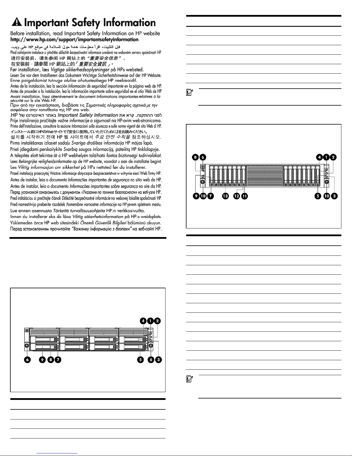
Identifying Chassis Components
Front Panel Components
Figure 1 Front panel components of a two Node system,8 LFF HDD
cage with optional front power/LED kit
Item Description
1 Power button of Node 2
2 Chassis UID LED Button
3 Power button of Node 4
Item Description
4 Health LED of Node 2
5 Health LED of Node 4
6 Thumbscrews for rack mounting
7 Hard disk drive (HDD) activity LED
8 Hard disk drive (HDD) location/error LED
9 Hard disk drive (HDD) bay
IMPORTANT: From the front side view, the right node is node 2
and the left node is node 4.
Figure 2 Front panel components of a four Node system,16 SFF HDD
cage with two optional front power/LED kit.
Item Description
1 Power button of Node 1
2 Chassis UID LED Button
3 Power button of Node 2
4 Health LED of Node 1
5 Health LED of Node 2
6 Power button of Node 3
7 Power button of Node 4
8 Health LED of Node 3
9 Health LED of Node 4
10 Thumbscrews for the rack mounting
11 Hard disk drive (HDD) activity LED
12 Hard disk drive (HDD) location/error LED
13 Hard disk drive (HDD) bay
IMPORTANT: From the front side view, the node in the top right
is node 1, bottom right is node 2, top left is node 3 and bottom
left is node 4.
Page 3
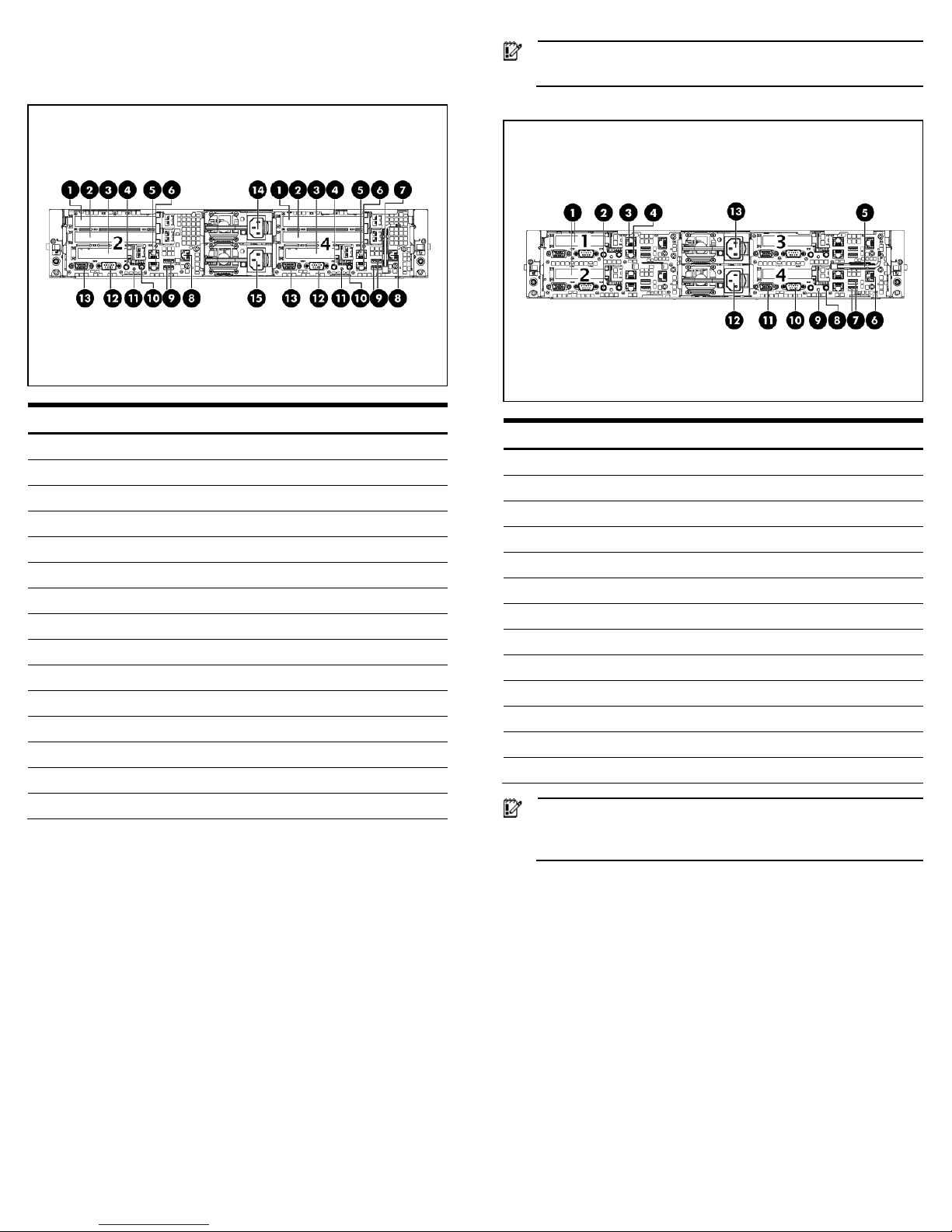
Rear Panel Components
Figure 3 Rear panel components of a two Node system
Item Description
1 PCIe Gen2 Full-height,full-length expansion card slot
2 PCIe Gen2 Full-height,half-length expansion card slot
3 PCIe Gen2 Low-profile expansion card slot
4 Server UID LED button
5 Shared 1Gb NIC2/Management Port (IPMI) (top)
6 1Gb NIC1 port (bottom)
7 T-10/T-15 driver
8 Dedicated Management Port (IPMI) (Optional)_
9 USB 2.0 ports
10 Server Power button
11 Server Health LED
12 Serial port
13 VGA port
14 Power supply cable socket 2
15 Power supply cable socket 1
IMPORTANT: From the rear side view, the right node is node 2
and the left node is node 1.
Figure 4 Rear panel components of a four Node system
Item Description
1 PCIe Gen2 Low-profile expansion card slot
2 Server UID LED button
3 Shared 1Gb NIC2/Management Port (IPMI) (top)
4 1Gb NIC1 port (bottom)
5 T-10/T-15 driver
6 Dedicated Management Port (IPMI) (Optional)_
7 USB 2.0 ports
8 Power button of Node 4
9 Health LED button of Node 4
10 Serial port
11 VGA port
12 Power supply cable socket 1
13 Power supply cable socket 2
IMPORTANT: From the rear side view, the node in the top right
is node 3,bottom right is node 4, top left is node 1 and bottom
left is node 2.
Server configuration resources
In addition to this Installation Sheet, other resources are available for
more information regarding the configuration and maintenance of
your server:
• For safety information and detailed procedures relating to
installation of options, refer to any installation instructions that
came with the option, as well as the HP ProLiant DL170h G6 series
Server Maintenance and Service Guide.
• For safety information and detailed procedures related to the rest
of the steps listed in the “Configuring the Server”section, refer to
relevant chapter of the HP ProLiant DL1000 Scalable System User
Guide.User Guide.
• For information relating to system BIOS configuration and
operating system installation, refer to relevant section of the HP
ProLiant DL170h G6 Server Software Configuration Guide.
Page 4
• Refer to the HP ProLiant DL170h G6 Server Easy Set-up CD for
additional information and updates not provided in this
installation sheet. You can also access additional information and
documentation from the HP website at http://www.hp.com/
,
either by connecting directly or through the Easy Set-up CD.
Server Configuration Overview
The steps listed below give an overview of the necessary setup
procedures for preparing the HP ProLiant DL170h Generation 6 Server
for operation:
1 Connect the AC power cord and peripheral devices.
2 Power up the server.
3 Press “F10” to enter BIOS setup.
4 Note the server BIOS version.
5 Verify the server BIOS version against the latest BIOS version
listed for this server on the HP website: http://www.hp.com.
6 If you do not have the latest BIOS, update the BIOS now. Refer to
the ProLiant DL170h G6 Server Maintenance and Service Guide
available on the HP website: http://www.hp.com.
7 Install a supported operating system of your choice. For detailed
procedures, refer to the documentation provided by the operating
system vendor. For a list of operating systems supported by your
ProLiant server, go to http://www.hp.com/go/supportos
.
Pre- and post-installation
procedures
When installing additional options in your HP ProLiant DL170h G6
Server, observe the following procedures:
Pre-installation procedures
1 Turn off the server and all the peripherals connected to it.
2 Disconnect the AC power cord(s) from the power supply connector
located on the server rear panel to reduce the risk of electrical shock.
3 If server is installed in a rack, remove server and place it on a flat
surface.
4 Remove the top cover by following the procedure described later in
the “Opening the Chassis” section.
Post-installation procedures
1 Be sure all components are installed according to the described
step-by-step instructions.
2 Check to make sure you have not left loose tools or parts inside the
server.
3 Reinstall the PCI cage, air baffle, peripherals, and system cables that
you have removed.
4 Reinstall the top cover.
5 Reinstall server into rack.
6 Connect all external cables and the AC power cord to the system.
7 Press the power button on the front panel to turn on the server.
Opening the Chassis
You need to remove the top cover before you can remove or replace a
server component.
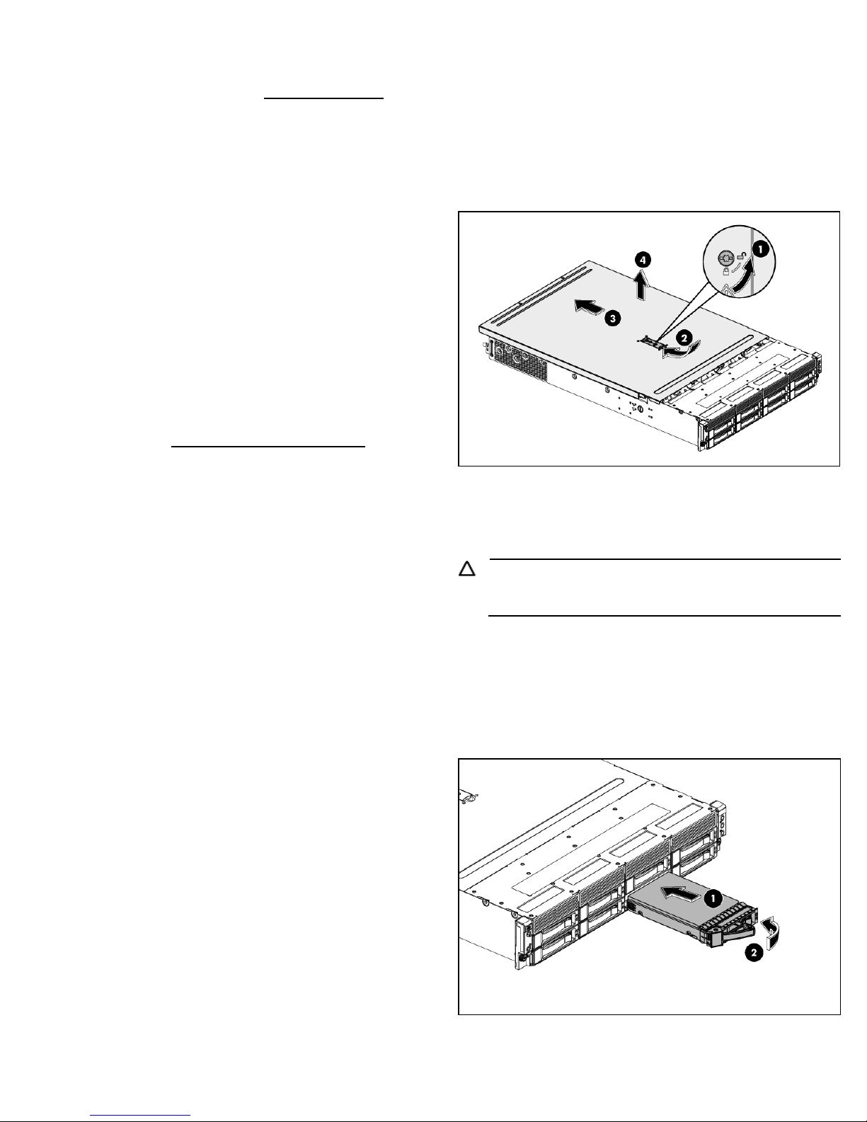
To remove the top cover:
1 Turn the screw to the side with the unlock sign with the T-10- wrench
provided. (Step 1 in Figure 5)
2 Pull the plastic button up. (Step 2 in Figure 5)
3 Slide the cover approximately 1.25 cm (0.5 in) toward the rear of the
unit and then lift the cover to detach it from the chassis. (Step 3 in
Figure 5)
4 Lift the top cover away from the chassis. (Step 4 in Figure 5)
Figure 5 Removing the top cover
Installing a Hard Drive
The drive bays on the front panel can accommodate up to 16 SFF hard
drives or 8 LFF hard drives, depending on the selected drive cage
option. The server supports both SAS and SATA hard drives.
CAUTION: Drives can be damaged by static electricity. Before
handling drives, touch an unpainted metal surface to discharge
static electricity.
To install a hard drive in the chassis.
1 Remove the hard drive blank from the front of system if installed.
2 Push the hard drive assembly into the drive bay until it stops (Step 1 in
Figure 6)
3 Press the HDD carrier latch inward until it clicks. (Step 2 in Figure 6)
Figure 6 Installing the hard drive assembly
Page 5
Installing a Memory Module
The following guidelines must be followed when memory modules are
being added or replaced:
1. Up to 128GB, using PC3-8500R DDR3 Registered (RDIMM)
memory, operating at 800MHz when fully populated in 16 slots.
Up to 24GB, using PC3-10600E DDR3 Unbuffered (UDIMM)
memory, operating at 1066MHz when fully populated at 2
DIMMs per Channel in 12 slots
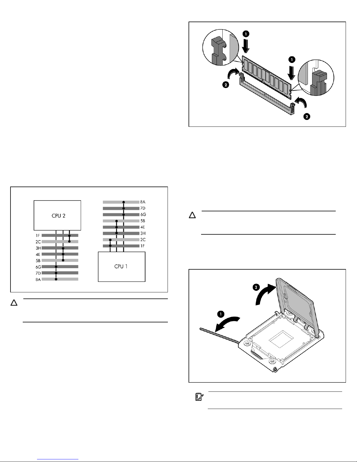
2. Sixteen DIMMs, eight DIMM sockets per processor,three per first
two channels and third channel with only two.
3. Supported configuration.
o One DIMM per processor: 8A for CPU1; 8A for CPU2.
o Three DIMMs per processor: 8A, 5B, 2C for CPU1; 8A, 5B,
2C for CPU2.
o Six DIMMs per processor: 8A, 7D, 5B, 4E, 2C, 1F for CPU1;
8A, 7D, 5B, 4E, 2C, 1F for CPU2
o DIMM population order processor socket 1: 8A, 5B, 2C, 7D,
4E, 1F, 6G, 3H.
o DIMM population order processor socket 2: 8A, 5B, 2C, 7D,
4E, 1F, 6G, 3H.
Figure 7 Population Order of DIMM Sockets
CAUTION: DIMMs can be damaged by improper handling.
Always use an anti-static wrist strap and grounding mat, and
discharge static electricity before touching DIMMs.
To install a memory module:
1. Align the notch on the bottom edge of the module with the keyed
surface of the DIMM slot and then press the module fully into the
slot.(Step 1 in Figure 8)
2. Firmly press the holding clips inward to secure the memory
module in place. (Step 2 in Figure 8)
Figure 8 Installing a memory module
DIMM slots are structured to ensure proper installation. If you insert a
DIMM but it does not fit easily into the slot, you may have inserted it
incorrectly. Reverse the orientation of the DIMM and insert it again.
Installing a Processor
The HP ProLiant DL170h G6 server supports Nehalem Processors High
Wattage 95W (Dual CPUs 64-bit), Nehalem Processors 80W (Dual
CPUs 64-bit), and Nehalem Processors Low Wattage 65W (Dual CPUs
64-bit).
To install the processor:
CAUTION: Failure to completely open the processor
locking lever prevents the processor from seating during
installation, leading to hardware damage.
1. Open the processor locking lever and the processor socket
retaining bracket. Do not remove the processor socket cover.
Figure 9 Opening the lever and bracket
IMPORTANT: Be sure the processor remains inside the
processor installation tool.
2. If the processor has separated from the installation tool, carefully
re-insert the processor in the tool. Handle the processor by the
edges only, and do not touch the bottom of the processor,
especially the contact area.
Page 6
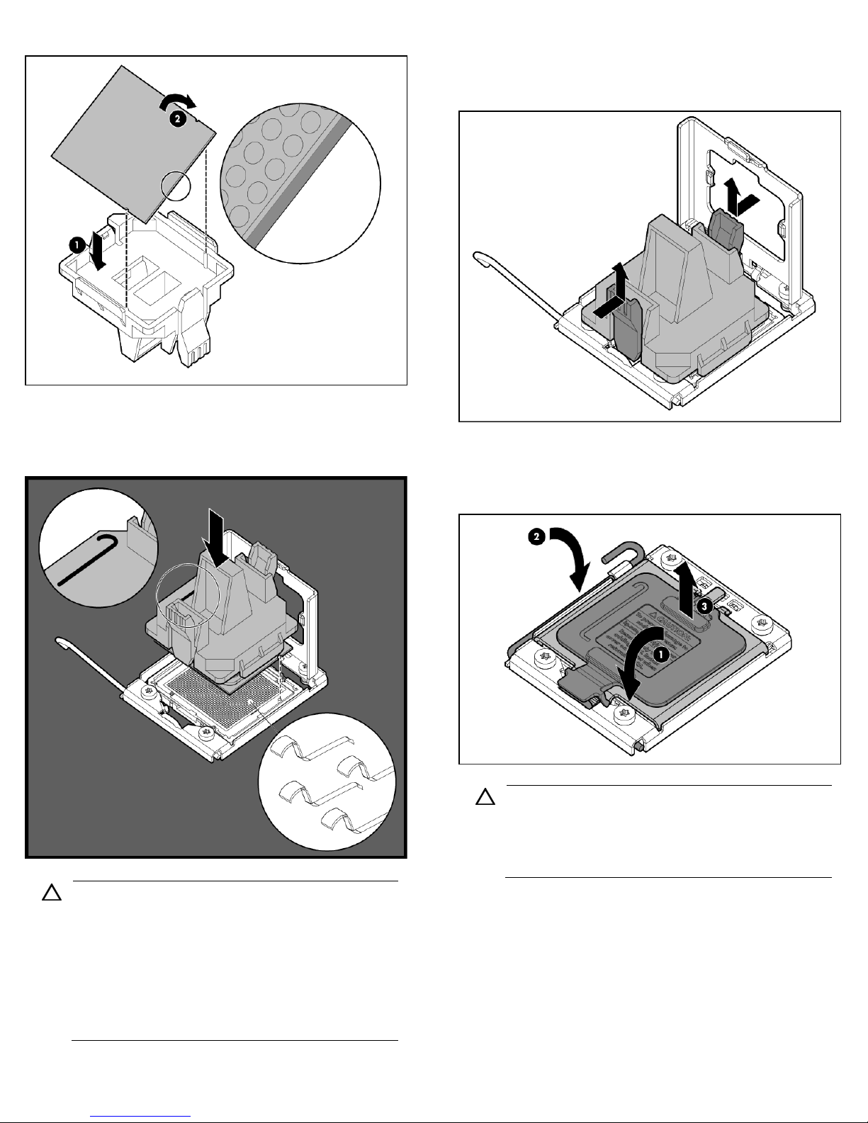
Figure 10 Reinserting the processor
3. Align the processor installation tool with the socket, and then
install the processor. THE PINS ON THE SYSTEM BOARD ARE
VERY FRAGILE AND EASILY DAMAGED.
Figure 11 Installing the processor
CAUTION: THE PINS ON THE SYSTEM BOARD ARE VERY
FRAGILE AND EASILY DAMAGED. To avoid damage to the
system board:
• Never install or remove a processor without using the
processor installation tool.
• Do not touch the processor socket contacts.
• Do not tilt or slide the processor when lowering the
processor into the socket.
4. Press the tabs on the processor installation tool to separate it from
the processor, and then remove the tool.
Figure 12 Removing the tool
5. Close the processor socket retaining bracket and the processor
locking lever. The processor socket cover is automatically
ejected. Remove the cover.
Figure 13 Closing the bracket and lever, removing cover
CAUTION: Be sure to close the processor socket retaining
bracket before closing the processor locking lever. The
lever should close without resistance. Forcing the lever
closed can damage the processor and socket, requiring
system board replacement.
For processor removal, reverse the above installation procedures,
using the processor tool to remove the processor.
Page 7
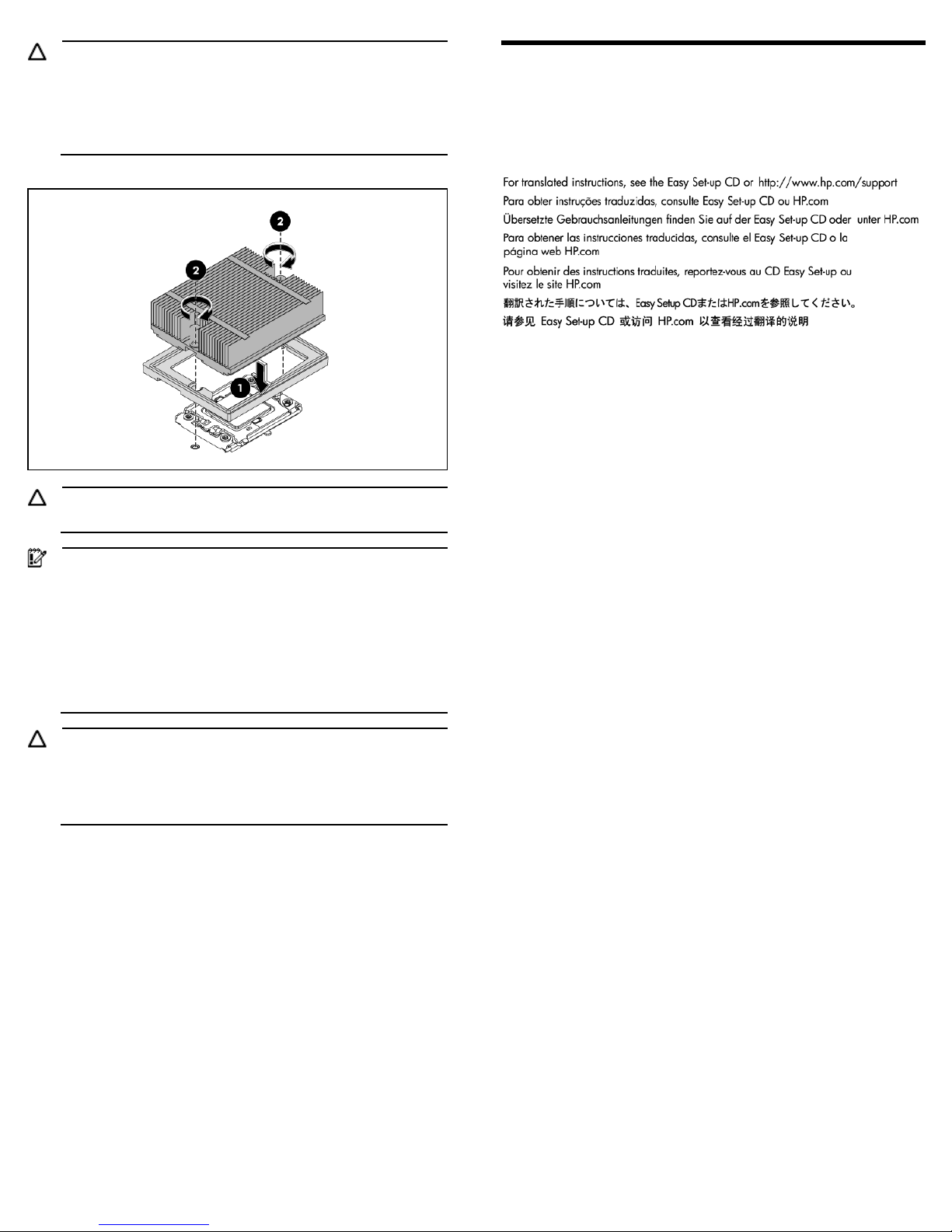
CAUTION: To prevent the heat sink from tilting to one side
during installation/removal, turn each screw a couple of turns,
alternatively between both of them, and then apply the final
torque. Do not over tighten the spring loaded screws to prevent
them from breaking off. A maximum torque of 4.5 inch-lb is set
for each screw.
Figure 14 Installing the heat sink assembly
CAUTION: Be sure that the heat sink sits squarely on the processor,
or overheating and damage to the processor may occur.
IMPORTANT: If the heat sink has been removed for any reason,
it is critical that you apply more thermal interface material to the
integrated heat spreader on the processor to ensure proper
thermal bonding between the processor and the heat sink.
Clean the contact surface of both the processor and heat sink
with an alcohol pad, then re-apply an HP-approved thermal
interface material before reinstalling the processor. Use a
pattern of five dots when applying the thermal interface
material—one dot in the center, and one dot at each corner.
CAUTION: To prevent the heat sink from tilting to one side
during installation removal procedures, use a diagonally
opposite pattern (an “X” pattern) when tightening the four
spring-loaded screws. Do not over tighten the heat sink’s
spring-loaded screws to prevent them from breaking off.
Additional Documentation
For additional documentation, refer to HP ProLiant DL170h G6 Easy
Set-up CD. You can also access additional information and
documentation from the HP external website, either by connecting
directly or through the Easy Set-up CD.
Page 8

Legal notices
© Copyright 2009, 2011 Hewlett-Packard Development Company, L.P.
The information contained herein is subject to change without notice. The only warranties for HP products and services are set forth in the express warranty statements
accompanying such products and services. Nothing herein should be construed as constituting an additional warranty. HP shall not be liable for technical or editorial
errors or omissions contained herein.
Microsoft, Windows, and Windows NT are U.S. registered trademarks of Microsoft Corporation.
Part Number 531486-004
January 2011 (Fourth Edition)
 Loading...