

Page 1

HP ProLiant BL e-Class System
Maintenance and Service Guide
June 2003 (Fifth Edition)
Part Number 249066-005
HP CONFIDENTIAL Codename: MacDuff Part Number: 249066-005 Last Saved On: 5/12/03 3:13 PM
Page 2

© 2003 Hewlett-Packard Development Company, L.P.
Microsoft and Windows are U.S. registered trademarks of Microsoft Corporation.
Hewlett-Packard Company shall not be liable for technical or editorial errors or omissions contained herein. The
information in this document is provided “as is” without warranty of any kind and is subject to change without
notice. The warranties for HP products are set forth in the express limited warranty statements accompanying such
products. Nothing herein should be construed as constituting an additional warranty.
HP ProLiant BL e-Class System Maintenance and Service Guide
June 2003 (Fifth Edition)
Part Number 249066-005
HP CONFIDENTIAL Codename: MacDuff Part Number: 249066-005 Last Saved On: 5/12/03 3:13 PM
Page 3

Contents
About This Guide
Audience Assumptions............................................................................................................................... vii
Important Safety Information..................................................................................................................... vii
Technician Notes........................................................................................................................................ vii
Where to Go for Additional Help.................................................................................................................ix
Integrated Management Log ..................................................................................................................ix
Telephone Numbers...............................................................................................................................ix
Chapter 1
Illustrated Parts Catalog
ProLiant BL e-Class Server Blade Enclosure Components (Exploded View).......................................... 1-2
ProLiant BL10e Server Blade Components (Exploded View).................................................................. 1-3
ProLiant BL10e G2 Server Blade Components (Exploded View)............................................................ 1-4
Spare Parts List.......................................................................................................................................... 1-5
Chapter 2
Removal and Replacement Procedures
Safety Considerations................................................................................................................................ 2-1
Electrostatic Discharge ....................................................................................................................... 2-1
Symbols on Equipment....................................................................................................................... 2-2
Rack Warnings and Cautions.............................................................................................................. 2-3
Enclosure and Server Blade Warnings and Cautions.......................................................................... 2-3
Hot-Plug Procedures.................................................................................................................................. 2-4
Hot-Plug Power Supplies.................................................................................................................... 2-5
Hot-Plug Fans ..................................................................................................................................... 2-6
Preparing for Non-Hot-Plug Procedures ................................................................................................... 2-7
Powering Down a Server Blade.......................................................................................................... 2-7
Powering Down the Enclosure............................................................................................................ 2-9
Removing a Server Blade ................................................................................................................. 2-12
Removing a Server Blade Blank....................................................................................................... 2-13
Removing the Interconnect Tray ...................................................................................................... 2-14
Removing the Server Blade Enclosure from the Rack ..................................................................... 2-15
Opening the Access Door ................................................................................................................. 2-16
Non-Hot-Plug Procedures ....................................................................................................................... 2-17
Fan Cage ........................................................................................................................................... 2-18
Fan Backplane Assembly.................................................................................................................. 2-20
Integrated Administrator Module ..................................................................................................... 2-21
Enclosure Status Assembly............................................................................................................... 2-22
HP ProLiant BL e-Class System Maintenance and Service Guide iii
HP CONFIDENTIAL Codename: MacDuff Part Number: 249066-005 Last Saved On: 5/12/03 3:13 PM
Page 4

Contents
DIMMs ..............................................................................................................................................2-24
Hard Drive Assembly........................................................................................................................2-27
Server Blade Battery .........................................................................................................................2-27
Center Wall Assembly.......................................................................................................................2-28
Swapping the Interconnect Tray........................................................................................................2-29
Chapter 3
Diagnostic Tools
Diagnostic Software and Firmware Tools .................................................................................................3-2
Hardware Diagnostic Tools .......................................................................................................................3-4
Diagnostic Adapter..............................................................................................................................3-4
Null-Modem Cable Pin-Out ................................................................................................................3-6
Chapter 4
Connectors, Switches, and LEDs
Connectors .................................................................................................................................................4-1
Enclosure Connectors..........................................................................................................................4-1
Server Blade Connectors .....................................................................................................................4-6
Diagnostic Adapter Connectors...........................................................................................................4-7
Switches .....................................................................................................................................................4-8
Front Panel Switches ........................................................................................................................... 4-8
Rear Panel Switches ............................................................................................................................4-9
Maintenance Switch ..........................................................................................................................4-10
LEDs ........................................................................................................................................................4-11
Enclosure Front Panel LEDs .............................................................................................................4-11
Enclosure Rear Panel LEDs ..............................................................................................................4-12
Fan Health LEDs ............................................................................................................................... 4-17
Server Blade and Diagnostic Adapter LEDs .....................................................................................4-18
Chapter 5
Specifications
ProLiant BL e-Class Server Blade Enclosure ............................................................................................ 5-2
Hot-Plug Power Supply .............................................................................................................................5-3
C-GbE Interconnect Switch Interconnect Tray.......................................................................................... 5-4
RJ-21 Patch Panel Interconnect Tray.........................................................................................................5-6
RJ-45 Patch Panel Interconnect Tray.........................................................................................................5-7
Server Blade Components..........................................................................................................................5-8
Operating and Performance Specifications .........................................................................................5-8
Memory (SDRAM DIMM) .................................................................................................................5-8
ATA Hard Drive Assembly................................................................................................................. 5-9
Index
iv HP ProLiant BL e-Class System Maintenance and Service Guide
HP CONFIDENTIAL Codename: MacDuff Part Number: 249066-005 Last Saved On: 5/12/03 3:13 PM
Page 5

Contents
List of Figures
1-1 Enclosure components ........................................................................................................................ 1-2
1-2 Server blade components .................................................................................................................... 1-3
1-3 Server blade components .................................................................................................................... 1-4
2-1 Removing a hot-plug power supply.................................................................................................... 2-5
2-2 Extending the fan cage........................................................................................................................ 2-6
2-3 Removing a hot-plug fan .................................................................................................................... 2-7
2-4 Pressing the power button on a server blade....................................................................................... 2-8
2-5 Pressing the enclosure power button on the rear panel (cables removed for clarity)........................ 2-10
2-6 Disconnecting the power cords from the rear panel ......................................................................... 2-11
2-7 Removing the server blade from the enclosure................................................................................. 2-12
2-8 Removing a one-bay server blade blank........................................................................................... 2-13
2-9 Removing a five-bay server blade blank........................................................................................... 2-13
2-10 Removing the interconnect tray from the enclosure ......................................................................... 2-14
2-11 Removing the enclosure from the rack ............................................................................................. 2-16
2-12 Opening the access door ................................................................................................................... 2-17
2-13 Disconnecting the fan cable from the power backplane ................................................................... 2-19
2-14 Removing the fan cage from the enclosure....................................................................................... 2-20
2-15 Removing the fan backplane assembly............................................................................................. 2-21
2-16 Removing the Integrated Administrator module from the interconnect tray.................................... 2-22
2-17 Disconnecting the enclosure status cable from the server blade backplane...................................... 2-23
2-18 Removing the enclosure status assembly from the enclosure........................................................... 2-24
2-19 Removing a DIMM........................................................................................................................... 2-25
2-20 DIMM socket keys for the ProLiant BL10e server blade................................................................. 2-25
2-21 DIMM socket keys for the ProLiant BL10e G2 server blade ........................................................... 2-26
2-22 Replacing a DIMM ........................................................................................................................... 2-26
2-23 Removing the hard drive assembly from a server blade................................................................... 2-27
2-24 Locating and removing the battery ................................................................................................... 2-28
2-25 Removing the center wall assembly from the enclosure................................................................... 2-29
2-26 Installing the Integrated Administrator module onto the interconnect tray ...................................... 2-30
3-1 Installing a diagnostic adapter ............................................................................................................ 3-5
4-1 ProLiant C-GbE Interconnect Switch connectors...............................................................................4-2
4-2 RJ-21 patch panel connectors ............................................................................................................. 4-3
4-3 RJ-45 patch panel connectors ............................................................................................................. 4-4
4-4 Fan cable connector on the center wall assembly ............................................................................... 4-5
4-5 Enclosure status cable connector on the server blade backplane........................................................ 4-5
4-6 Identifying the server blade connectors .............................................................................................. 4-6
4-7 Diagnostic adapter connectors ............................................................................................................ 4-7
4-8 Server blade and enclosure front panel buttons .................................................................................. 4-8
4-9 Enclosure rear panel buttons............................................................................................................... 4-9
4-10 Maintenance switch .......................................................................................................................... 4-10
4-11 Enclosure front panel LEDs.............................................................................................................. 4-11
4-12 Rear panel LEDs with the interconnect switch interconnect tray ..................................................... 4-12
4-13 Rear panel LEDs with the RJ-21 patch panel interconnect tray ....................................................... 4-14
4-14 Rear panel LEDs with RJ-45 patch panel interconnect tray ............................................................. 4-16
4-15 Hot-plug fan health LEDs................................................................................................................. 4-17
4-16 Server blade LEDs ............................................................................................................................ 4-18
4-17 Diagnostic adapter LEDs .................................................................................................................. 4-19
HP ProLiant BL e-Class System Maintenance and Service Guide v
HP CONFIDENTIAL Codename: MacDuff Part Number: 249066-005 Last Saved On: 5/12/03 3:13 PM
Page 6

Contents
List of Tables
1-1 Spare Parts List.................................................................................................................................... 1-5
3-1 Diagnostic Tools..................................................................................................................................3-2
3-2 Cable Pin-Out for a Null-Modem Cable .............................................................................................3-6
4-1 ProLiant C-GbE Interconnect Switch Connectors...............................................................................4-2
4-2 RJ-21 Patch Panel Connectors.............................................................................................................4-3
4-3 RJ-45 Patch Panel Connectors.............................................................................................................4-4
4-4 Server Blade Connectors .....................................................................................................................4-6
4-5 Diagnostic Adapter Connectors...........................................................................................................4-7
4-6 Server Blade and Enclosure Front Panel Buttons................................................................................4-8
4-7 Enclosure Rear Panel Buttons .............................................................................................................4-9
4-8 Maintenance Switch ..........................................................................................................................4-10
4-9 Enclosure Front Panel LEDs .............................................................................................................4-11
4-10 Rear Panel LEDs with the Interconnect Switch Interconnect Tray...................................................4-12
4-11 Rear Panel LEDs with RJ-21 Patch Panel Interconnect Tray............................................................4-14
4-12 Rear Panel LEDs with RJ-45 Patch Panel Interconnect Tray............................................................4-16
4-13 Hot-Plug Fan Health LEDs ...............................................................................................................4-18
4-14 Server Blade and Diagnostic Adapter LEDs .....................................................................................4-20
5-1 ProLiant BL e-Class Server Blade Enclosure Specifications..............................................................5-2
5-2 Hot-Plug Power Supply Specifications ...............................................................................................5-3
5-3 C-GbE Interconnect Switch Interconnect Tray Specifications............................................................5-4
5-4 RJ-21 Patch Panel Interconnect Tray Specifications........................................................................... 5-6
5-5 RJ-45 Patch Panel Interconnect Tray Specifications........................................................................... 5-7
5-6 Server Blade Operating and Performance Specifications....................................................................5-8
5-7 ProLiant BL10e Server Blade SDRAM DIMM Specifications ..........................................................5-8
5-8 ProLiant BL10e G2 Server Blade DDR SDRAM DIMM Specifications ...........................................5-9
5-9 ATA Hard Drive Assembly Specifications .........................................................................................5-9
vi HP ProLiant BL e-Class System Maintenance and Service Guide
HP CONFIDENTIAL Codename: MacDuff Part Number: 249066-005 Last Saved On: 5/12/03 3:13 PM
Page 7

This maintenance and service guide can be used for reference when servicing HP ProLiant
BL e-Class Systems.
WARNING: To reduce the risk of personal injury from electric shock and hazardous
energy levels, only authorized service technicians should attempt to repair this
equipment. Improper repairs can create conditions that are hazardous.
Audience Assumptions
This guide is for service technicians. HP assumes you are qualified in the servicing of
computer equipment and trained in recognizing hazard in products with hazardous energy
levels and are familiar with weight and stability precautions for rack installations.
Important Safety Information
About This Guide
Before installing this product, read the Important Safety Information document provided.
Technician Notes
WARNING: Only authorized technicians trained by HP should attempt to repair this
equipment. All troubleshooting and repair procedures are detailed to allow only
subassembly/module-level repair. Because of the complexity of the individual boards
and subassemblies, no one should attempt to make repairs at the component level or
to make modifications to any printed wiring board. Improper repairs can create a safety
hazard.
WARNING: To reduce the risk of personal injury from electric shock and hazardous
energy levels, do not exceed the level of repairs specified in these procedures.
Because of the complexity of the individual boards and subassemblies, do not attempt
to make repairs at the component level or to make modifications to any printed wiring
board. Improper repairs can create conditions that are hazardous.
HP ProLiant BL e-Class System Maintenance and Service Guide vii
HP CONFIDENTIAL Codename: MacDuff Part Number: 249066-005 Last Saved On: 5/12/03 3:13 PM
Page 8

About This Guide
WARNING: To reduce the risk of electric shock or damage to the equipment:
• Disconnect power from the system by unplugging all power cords from the power
supplies.
• Do not disable the power cord grounding plug. The grounding plug is an important
safety feature.
• Plug the power cord into a grounded (earthed) electrical outlet that is easily
accessible at all times.
CAUTION: To properly ventilate the system, you must provide at least 7.6 cm (3.0 in) of
clearance at the front and back of the server.
CAUTION: The computer is designed to be electrically grounded (earthed). To ensure proper
operation, plug the AC power cord into a properly grounded AC outlet only.
NOTE: Any indications of component replacement or printed wiring board modifications may void any
warranty.
viii HP ProLiant BL e-Class System Maintenance and Service Guide
HP CONFIDENTIAL Codename: MacDuff Part Number: 249066-005 Last Saved On: 5/12/03 3:13 PM
Page 9

Where to Go for Additional Help
In addition to this guide, the following information sources are available:
• User documentation
• Service Quick Reference Guide
• Service training guides
• Service advisories and bulletins
• QuickFind information services
• Insight Manager 7 software
• Quickspecs
For additional copies, visit the HP website:
www.hp.com
Integrated Management Log
About This Guide
The server includes an integrated, nonvolatile management log that contains fault and
management information. The contents of the Integrated Management Log (IML) can be
viewed with Insight Manager 7.
Telephone Numbers
For the name of the nearest HP authorized reseller:
• In the United States, call 1-800-345-1518.
• In Canada, call 1-800-263-5868.
For HP technical support:
• In the United States and Canada, call 1-800-652-6672.
• Outside the United States and Canada, refer to
www.hp.com
HP ProLiant BL e-Class System Maintenance and Service Guide ix
HP CONFIDENTIAL Codename: MacDuff Part Number: 249066-005 Last Saved On: 5/12/03 3:13 PM
Page 10

1
Illustrated Parts Catalog
This chapter provides the illustrated parts breakdown and spare parts list for the HP ProLiant
BL e-Class system. See Table 1-1 for the names of referenced spare parts.
HP ProLiant BL e-Class System Maintenance and Service Guide 1-1
HP CONFIDENTIAL Codename: Kerr Part Number: 249066-005 Last Saved On: 5/12/03 2:58 PM
Page 11

Illustrated Parts Catalog
ProLiant BL e-Class Server Blade Enclosure Components
(Exploded View)
Figure 1-1: Enclosure components
1-2 HP ProLiant BL e-Class System Maintenance and Service Guide
HP CONFIDENTIAL Codename: Kerr Part Number: 249066-005 Last Saved On: 5/12/03 2:58 PM
Page 12

Illustrated Parts Catalog
ProLiant BL10e Server Blade Components (Exploded View)
Figure 1-2: Server blade components
HP ProLiant BL e-Class System Maintenance and Service Guide 1-3
HP CONFIDENTIAL Codename: Kerr Part Number: 249066-005 Last Saved On: 5/12/03 2:58 PM
Page 13

Illustrated Parts Catalog
ProLiant BL10e G2 Server Blade Components (Exploded View)
Figure 1-3: Server blade components
1-4 HP ProLiant BL e-Class System Maintenance and Service Guide
HP CONFIDENTIAL Codename: Kerr Part Number: 249066-005 Last Saved On: 5/12/03 2:58 PM
Page 14

Illustrated Parts Catalog
Spare Parts List
Table 1-1: Spare Parts List
Item Description Spare Part Number
1 Hot-plug power supply (600W) 253082-001
2 Center wall assembly 253081-001
3 ProLiant BL e-Class Integrated Administrator module 253075-001
4 Fan backplane assembly (with cable*) 253080-001
5 Fan cage 253086-001
6 Hot-plug fan, 60-mm 253079-001
7 Enclosure status assembly 253083-001
8 Server blade blank kit* 253088-001
a) five-bay blank *
b) one-bay blank *
9a ProLiant BL10e server blade
a) 700-MHz processor model 253087-001
b) 800-MHz processor model * 289227-001
c) 900-MHz processor model * 313346-001
9b ProLiant BL10e G2 server blade
1-GB processor model 333507-001
10 Diagnostic adapter * 253089-001
11 Lithium battery, 3.3-V 234556-001
12 ATA hard drive assembly
a) 30-GB hard drive, 4200 RPM 258317-001
b) 40-GB hard drive, 4200 RPM * 289228-001
c) 40-GB hard drive, 5400 RPM * 313347-001
13 DIMM A: 512-MB registered 133-MHz SDRAM 159227-001
DIMM B: 256-MB registered 133-MHz SDRAM * 159377-001
DIMM C: 128-MB registered 133-MHz SDRAM * 159226-001
Server Blade Enclosure Components (Figure 1-1)
Server Blade Components
Mass Storage Devices
Memory for ProLiant BL10e server blade
* Not shown
HP ProLiant BL e-Class System Maintenance and Service Guide 1-5
HP CONFIDENTIAL Codename: Kerr Part Number: 249066-005 Last Saved On: 5/12/03 2:58 PM
continued
Page 15

Illustrated Parts Catalog
Table 1-1: Spare Parts List continued
Item Description Spare Part Number
13 DIMM A: 512-MB registered PC2100 DDR SDRAM 300699-001
DIMM B: 256-MB registered PC2100 DDR SDRAM * 300700-001
DIMM C: 1-GB registered PC2100 DDR SDRAM * 300701-001
14 Rack-mounting hardware kit * 270463-001
15 Hardware kit * 253084-001
Thumbscrew, rack mount
Screw (panel board)
Null-modem cable
Screw (enclosure status)
Retractable thumbscrew
16 Plastics kit * 253085-001
Air baffle, fan cage
Plastic stand off
Bezel latch
Hood latch, top cover
Bezel, front
17 Country kit * 258319-001
18 Return kit, pack box and cushions for the enclosure * 253090-001
19 Return kit, pack box and cushions for a single server blade * 259490-001
20 Telco rack-mounting kit * 270464-001
21 RJ-21 to RJ-45 cable * 259491-001
22 ProLiant BL e-Class C-GbE Interconnect Switch interconnect
23 RJ-21 patch panel interconnect tray 253078-001
24 RJ-45 patch panel interconnect tray 253076-001
Memory for ProLiant BL10e G2 server blade
Rack-Mounting Hardware
Miscellaneous
Options
253077-001
tray
25 Enclosure shipping bracket kit * 293119-B21
* Not shown
1-6 HP ProLiant BL e-Class System Maintenance and Service Guide
HP CONFIDENTIAL Codename: Kerr Part Number: 249066-005 Last Saved On: 5/12/03 2:58 PM
Page 16

Removal and Replacement Procedures
This chapter provides subassembly/module-level removal and replacement procedures for HP
ProLiant BL e-Class enclosures and server blades.
Safety Considerations
Before performing service procedures, review the following safety information.
Electrostatic Discharge
A discharge of static electricity can damage static-sensitive devices or microcircuitry.
Proper packaging and grounding techniques are necessary to prevent damage. To prevent
electrostatic damage, observe the following precautions:
Transport products in static-safe containers such as conductive tubes, bags, or boxes. •
•
Keep electrostatic-sensitive parts in their containers until they arrive at static-free
stations.
2
•
Cover workstations with approved static-dissipating material. Use a wrist strap connected
to the work surface and properly grounded tools and equipment.
•
Keep the work area free of nonconductive materials such as ordinary plastic assembly
aids and foam packing.
•
Always be properly grounded when touching a static-sensitive component or assembly.
•
Avoid touching pins, leads, or circuitry.
•
Use conductive field service tools.
HP ProLiant BL e-Class System Maintenance and Service Guide 2-1
HP CONFIDENTIAL Codename: Kerr Part Number: 249066-004 Last Saved On: 5/12/03 3:00 PM
Page 17

Removal and Replacement Procedures
Symbols on Equipment
These symbols may be located on equipment in areas where hazardous conditions may exist.
Weight kg
Weight lb
This symbol in conjunction with any of the following
symbols indicates the presence of a potential hazard. The
potential for injury exists if warnings are not observed.
Consult the documentation for specific details.
This symbol indicates the presence of hazardous energy
circuits or electric shock hazards. Refer all servicing to
qualified personnel.
WARNING: To reduce the risk of injury from electric
shock hazards, do not open this enclosure. Refer all
maintenance, upgrades, and servicing to qualified
personnel.
This symbol indicates the presence of electric shock
hazards. The area contains no user or field serviceable
parts. Do not open for any reason.
WARNING: To reduce the risk of injury from electric
shock hazards, do not open this enclosure.
This symbol on an RJ-45 receptacle indicates a Network
Interface Connection.
WARNING: To reduce the risk of electric shock, fire, or
damage to the equipment, do not plug telephone or
telecommunications connectors into this receptacle.
This symbol indicates the presence of a hot surface or hot
component. If this surface is contacted, the potential for
injury exists.
WARNING: To reduce the risk of injury from a hot
component, allow the surface to cool before touching.
These symbols on power supplies or systems
indicate the equipment is supplied by multiple
sources of power.
WARNING: To reduce the risk of injury from
electric shock, remove all power cords to
completely disconnect power from the system.
This symbol indicates that the component exceeds
the recommended weight for one individual to handle
safely.
WARNING: To reduce the risk of personal injury or
damage to the equipment, observe local
occupational health and safety requirements and
guidelines for manual material handling.
2-2 HP ProLiant BL e-Class System Maintenance and Service Guide
HP CONFIDENTIAL Codename: Kerr Part Number: 249066-004 Last Saved On: 5/12/03 3:00 PM
Page 18

Rack Warnings and Cautions
WARNING: To reduce the risk of personal injury or damage to the equipment,
adequately stabilize the rack before extending a component outside the rack. Extend
only one component at a time. A rack may become unstable if more than one
component is extended.
WARNING: To reduce the risk of personal injury or damage to the equipment:
• Extend the leveling jacks to the floor.
• Rest the full weight of the rack on the leveling jacks.
• Attach the stabilizers to the rack if it is a single rack installation.
• Couple the racks together in multiple rack installations.
WARNING: When installing the server blade enclosure in a telco rack, adequately
secure the rack frame to the building structure at the top and bottom.
WARNING: To reduce the risk of personal injury or damage to the equipment, use two
or more people to safely unload the rack from the pallet. An empty 42U rack weighs
115 kg (253 lb), is over 2.1 m (7 ft) tall, and may become unstable when moved on its
casters. Handle the rack from both sides as it rolls down the ramp from the pallet. Do
not stand in front of the rack.
CAUTION: Always begin by mounting the heaviest item on the bottom of the rack. Continue
to populate the rack from the bottom to the top.
Removal and Replacement Procedures
Enclosure and Server Blade Warnings and Cautions
WARNING: To reduce the risk of personal injury from hot surfaces, allow the drives
and the internal system components to cool before touching.
WARNING: To reduce the risk of electrical shock or damage to the equipment:
• Plug the power cords into a grounded (earthed) electrical outlet that is easily
accessible at all times.
• Unplug the power cord from each power supply to disconnect power to the
enclosure.
WARNING: Because the rack enables you to stack enclosure components in a vertical
rather than a horizontal plane, you must take precautions to provide for rack stability
and safety to protect both personnel and property. Heed all cautions and warnings
throughout the installation instructions that came with the enclosure.
WARNING: There is a risk of injury or damage to the equipment from hazardous
energy. The access door provides access to hazardous energy currents. The door
should remain locked during normal operation, or the server blade enclosure should be
installed in a controlled access location where only qualified personnel have access to
the system.
HP ProLiant BL e-Class System Maintenance and Service Guide 2-3
HP CONFIDENTIAL Codename: Kerr Part Number: 249066-004 Last Saved On: 5/12/03 3:00 PM
Page 19

Removal and Replacement Procedures
CAUTION: Protect the server blade enclosure from power fluctuations and temporary
interruptions with a regulating uninterruptible power supply (UPS). This device protects the
hardware from damage caused by power surges and voltage spikes and keeps the system in
operation during a power failure.
Hot-Plug Procedures
You do not need to power down the enclosure to remove or replace hot-plug components.
Hot-plug components in the ProLiant BL e-Class System include:
Hot-plug power supplies •
• Hot-plug fans
NOTE: Port-color denotes hot-plug components.
2-4 HP ProLiant BL e-Class System Maintenance and Service Guide
HP CONFIDENTIAL Codename: Kerr Part Number: 249066-004 Last Saved On: 5/12/03 3:00 PM
Page 20

Hot-Plug Power Supplies
CAUTION: To avoid a thermal event, do not remove a failed power supply until a replacement
power supply is available.
IMPORTANT: You can use the Integrated Administrator to identify a failed power supply. Refer to the
HP ProLiant BL e-Class Integrated Administrator User Guide for details.
To remove a redundant hot-plug power supply:
1. Disconnect the power cord from the AC power source.
2. Disconnect the power cord from the hot-plug power supply.
3. Press the port-colored release button (1).
4. Open the hot-plug power supply handle (2).
5. Pull the hot-plug power supply out of the enclosure (3).
Removal and Replacement Procedures
Figure 2-1: Removing a hot-plug power supply
Reverse steps 1 through 5 to replace the hot-plug power supply.
HP ProLiant BL e-Class System Maintenance and Service Guide 2-5
HP CONFIDENTIAL Codename: Kerr Part Number: 249066-004 Last Saved On: 5/12/03 3:00 PM
Page 21

Removal and Replacement Procedures
Hot-Plug Fans
IMPORTANT: You can use the Integrated Administrator to identify a failed hot-plug fan. Refer to the
HP ProLiant BL e-Class Integrated Administrator User Guide for details.
To remove a hot-plug fan:
1. Press the release latch on the fan cage (1).
2. Pull the fan cage out of the enclosure until it locks in the open position (2).
Figure 2-2: Extending the fan cage
3. Identify the failed hot-plug fan by observing the fan status LED on each hot-plug fan. An
amber LED indicates a failed hot-plug fan.
2-6 HP ProLiant BL e-Class System Maintenance and Service Guide
HP CONFIDENTIAL Codename: Kerr Part Number: 249066-004 Last Saved On: 5/12/03 3:00 PM
Page 22

4. Remove the hot-plug fan from the fan cage.
Figure 2-3: Removing a hot-plug fan
Removal and Replacement Procedures
Reverse steps 1 through 4 to replace a hot-plug fan.
Preparing for Non-Hot-Plug Procedures
Replacement of non-hot-plug components may require some or all the following procedures:
Powering down a server blade •
•
Powering down the enclosure
•
Removing a server blade
•
Removing a server blade blank
•
Removing the interconnect tray
•
Removing the server blade enclosure from the rack
•
Opening the access door
Powering Down a Server Blade
To power down a server blade:
1. Be sure that the server blade is not active.
For specific information about server blade LEDs, see Table 4-14 in Chapter 4,
“Connectors, Switches, and LEDs.”
2. If the server blade is active, notify users and stop applications as necessary.
3. Shut down the operating system. This may shut off server blade power.
HP ProLiant BL e-Class System Maintenance and Service Guide 2-7
HP CONFIDENTIAL Codename: Kerr Part Number: 249066-004 Last Saved On: 5/12/03 3:00 PM
Page 23

Removal and Replacement Procedures
If the server blade still has power after the operating system has been shut down, two
different methods are available for powering down a ProLiant BL e-Class server blade:
Graceful shutdown •
•
Emergency shutdown
Performing a Graceful Shutdown
Two methods are available for performing a graceful shutdown on a ProLiant BL e-Class
server blade:
•
Using the Integrated Administrator
•
Pressing the server blade power button
Using the Integrated Administrator
You can perform a graceful shutdown of a ProLiant BL e-Class server blade by using the
“Power Off” option in the Integrated Administrator. To power down a server blade using the
Integrated Administrator, refer to the HP ProLiant BL e-Class Integrated Administrator User
Guide for detailed instructions.
Pressing the Server Blade Power Button
You can also perform a graceful shutdown of a ProLiant BL e-Class server blade by pressing
the power button on the front of the server blade.
Figure 2-4: Pressing the power button on a server blade
2-8 HP ProLiant BL e-Class System Maintenance and Service Guide
HP CONFIDENTIAL Codename: Kerr Part Number: 249066-004 Last Saved On: 5/12/03 3:00 PM
Page 24

Performing an Emergency Shutdown
Two methods are available for performing an emergency shutdown on a server blade:
Using the Integrated Administrator •
• Pressing and holding the server blade power button
Using the Integrated Administrator
You can perform an emergency shutdown of a ProLiant BL e-Class server blade by using the
“Power Off” option in the Integrated Administrator. To power down a server blade using the
Integrated Administrator, refer to the HP ProLiant BL e-Class Integrated Administrator User
Guide for detailed instructions.
Pressing and Holding the Server Blade Power Button
You can also perform an emergency shutdown of a ProLiant BL e-Class server blade by
pressing and holding the power button on the front of the server blade for 4 seconds.
CAUTION: Performing an emergency shutdown on a server blade may result in the loss of
any unsaved data.
Removal and Replacement Procedures
Repeat this step to power up a server blade.
Powering Down the Enclosure
Two different methods are available for powering down a ProLiant BL e-Class enclosure:
Graceful shutdown •
•
Emergency shutdown
Performing a Graceful Shutdown
Two methods are available for performing a graceful shutdown on a ProLiant BL e-Class
enclosure:
•
Using the Integrated Administrator
•
Pressing the server blade power button
Using the Integrated Administrator
You can perform a graceful shutdown of a ProLiant BL e-Class enclosure by using the
“Power Off” option in the Integrated Administrator. To power down the enclosure using the
Integrated Administrator, refer to the HP ProLiant BL e-Class Integrated Administrator User
Guide for detailed instructions.
HP ProLiant BL e-Class System Maintenance and Service Guide 2-9
HP CONFIDENTIAL Codename: Kerr Part Number: 249066-004 Last Saved On: 5/12/03 3:00 PM
Page 25

Removal and Replacement Procedures
CAUTION: If the Integrated Administrator cannot perform a graceful shutdown of the
enclosure and all server blades, after five minutes, the Integrated Administrator will perform
an emergency shutdown of the enclosure and all server blades. Performing an emergency
shutdown on the enclosure may result in the loss of any unsaved data on all server blades in
that enclosure.
Pressing the Enclosure Power Button
You can also perform a graceful shutdown of a ProLiant BL e-Class enclosure and all the
server blades by pressing the enclosure power button on the rear of the enclosure. If the
operating system is Microsoft Windows 2000 or Windows Server 2003, the enclosure
automatically performs a graceful shutdown of all server blades, and then removes power
from the enclosure. If the operating system is RedHat Linux, you must have the Linux Health
driver installed in order for the server blades to shut down gracefully.
Figure 2-5: Pressing the enclosure power button on the rear panel
(cables removed for clarity)
Performing an Emergency Shutdown
Two methods are available for performing an emergency shutdown on the enclosure and all
server blades:
Using the Integrated Administrator •
• Pressing and holding the enclosure power button
2-10 HP ProLiant BL e-Class System Maintenance and Service Guide
HP CONFIDENTIAL Codename: Kerr Part Number: 249066-004 Last Saved On: 5/12/03 3:00 PM
Page 26

Removal and Replacement Procedures
Using the Integrated Administrator
The Integrated Administrator performs an emergency shutdown of the enclosure and all
server blades only after trying for 5 minutes to perform a graceful shutdown. See the
“Performing a Graceful Shutdown” section in this chapter. If, after 5 minutes, the Integrated
Administrator cannot perform a graceful shutdown on the enclosure and all server blades, the
Integrated Administrator performs an automatic emergency shutdown. To power down the
enclosure using the Integrated Administrator, refer to the HP ProLiant BL e-Class Integrated
Administrator User Guide for detailed instructions.
Pressing and Holding the Enclosure Power Button
You can also perform an emergency shutdown of a ProLiant BL e-Class enclosure and all
server blades by pressing and holding the power button for 4 seconds.
CAUTION: Performing an emergency shutdown on a server blade may result in the loss of
any unsaved data on all server blades in that enclosure.
Repeat this step to power up the ProLiant BL e-Class enclosure.
Removing AC Power Completely
To completely remove power from the enclosure and all server blades, after powering down
the enclosure, disconnect both of the power cords from the AC power source, then disconnect
both of the power cords from the rear panel of the enclosure.
Figure 2-6: Disconnecting the power cords from the rear panel
Reverse these steps to power up the enclosure.
HP ProLiant BL e-Class System Maintenance and Service Guide 2-11
HP CONFIDENTIAL Codename: Kerr Part Number: 249066-004 Last Saved On: 5/12/03 3:00 PM
Page 27
Removal and Replacement Procedures
Removing a Server Blade
CAUTION: Integrated Administrator security settings are assigned to server blade bays, not
to server blades. If server blades change locations within the enclosure, Integrated
Administrator settings must also be adjusted to ensure accurate security. Refer to the HP
ProLiant BL e-Class Integrated Administrator User Guide for more information on security
settings.
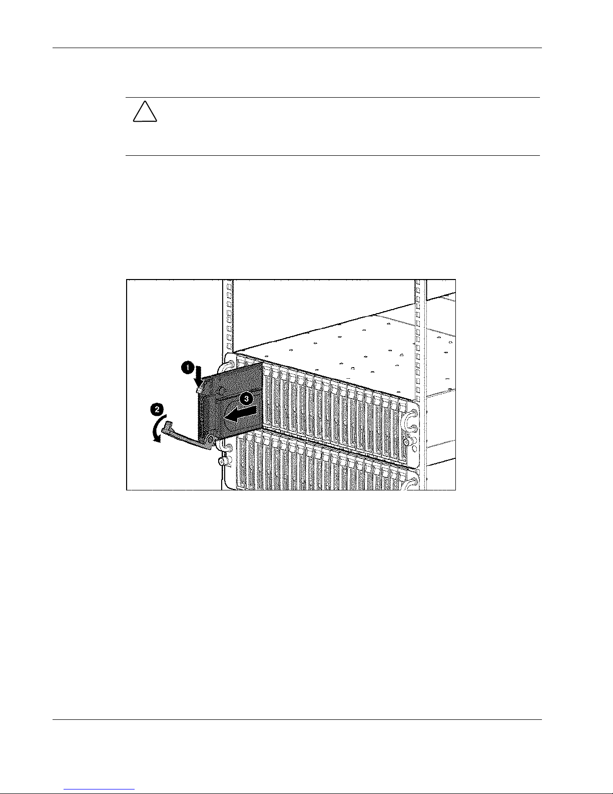
To remove a server blade from the enclosure:
1. Power down the server blade. See the “Powering Down a Server Blade” section in this
chapter.
2. Press the release latch (1).
3. Pull down the ejector lever (2).
4. Remove the server blade from the enclosure (3).
Figure 2-7: Removing the server blade from the enclosure
Reverse steps 1 through 4 to replace a server blade.
2-12 HP ProLiant BL e-Class System Maintenance and Service Guide
HP CONFIDENTIAL Codename: Kerr Part Number: 249066-004 Last Saved On: 5/12/03 3:00 PM
Page 28
Removing a Server Blade Blank
CAUTION: To avoid thermal events, be sure that each server blade bay contains a server
blade or server blade blank while the enclosure is powered up.
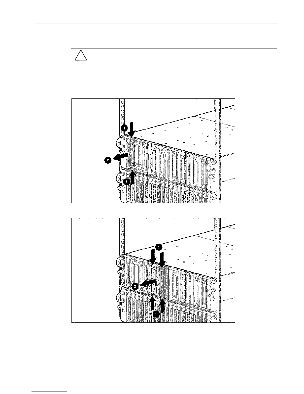
To remove the server blade blank:
1. Press the ejector tabs on the server blade blank (1).
2. Remove the server blade blank from the enclosure (2).
Removal and Replacement Procedures
Figure 2-8: Removing a one-bay server blade blank
Figure 2-9: Removing a five-bay server blade blank
Reverse steps 1 and 2 to replace the server blade blank.
HP ProLiant BL e-Class System Maintenance and Service Guide 2-13
HP CONFIDENTIAL Codename: Kerr Part Number: 249066-004 Last Saved On: 5/12/03 3:00 PM
Page 29
Removal and Replacement Procedures
Removing the Interconnect Tray
To remove the interconnect tray:
1. Power down each server blade. See the “Powering Down a Server Blade” section in this
chapter.
2. Power down the enclosure. See the “Powering Down the Enclosure” section in this
chapter.
3. Disconnect all cables and power cords from the AC power source.
4. Disconnect all cables and power cords from the enclosure rear panel.
IMPORTANT: Perform steps 5 and 6 simultaneously in both power-supply bays.
5. Remove both hot-plug power supplies. See the “Hot-Plug Power Supplies” section in this
chapter.
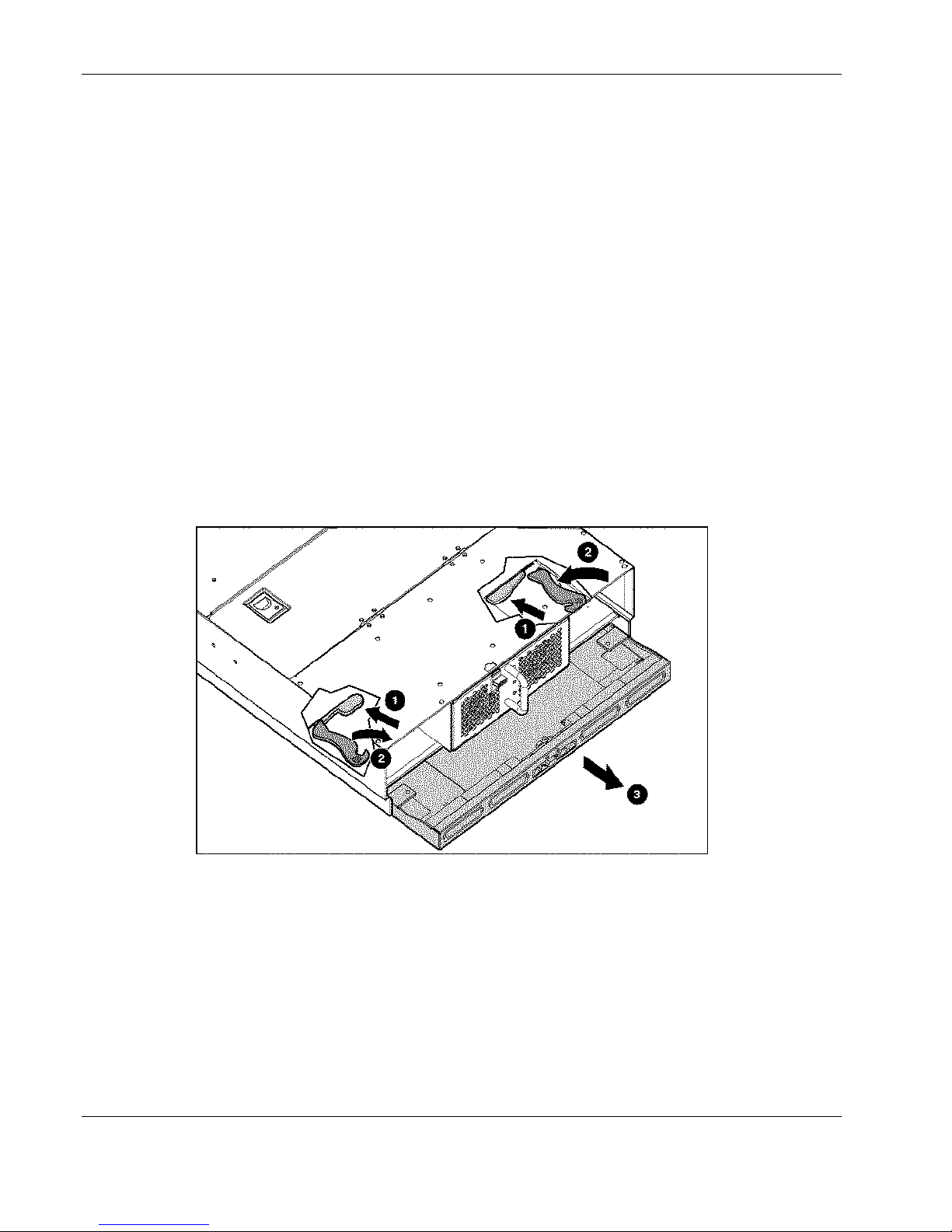
6. Release the locking latches securing the interconnect tray in the enclosure (1).
7. Pull the release latches toward the rear of the enclosure (2).
8. Remove the interconnect tray from the enclosure (3).
Figure 2-10: Removing the interconnect tray from the enclosure
Reverse steps 1 through 8 to replace the interconnect tray.
IMPORTANT: When installing the interconnect tray, be sure that the release latches are in the open
position. When closing the release latches on the interconnect tray, be sure that the locking latches
click audibly into place.
2-14 HP ProLiant BL e-Class System Maintenance and Service Guide
HP CONFIDENTIAL Codename: Kerr Part Number: 249066-004 Last Saved On: 5/12/03 3:00 PM
Page 30
Removing the Server Blade Enclosure from the Rack
WARNING: Rack rails do not have safety latches. Be sure that at least two persons are
available to prevent the enclosure from falling and causing bodily harm when removing
it from the rack.
To remove the server blade enclosure from the rack:
1. Power down each server blade. See the “Powering Down a Server Blade” section in this
chapter.
2. Power down the enclosure. See the “Powering Down the Enclosure” section in this
chapter.
3. Disconnect all cables and power cords from the AC power source.
4. Disconnect all cables and power cords from the enclosure rear panel.
5. Remove all server blades and server blade blanks. See the “Removing a Server Blade”
and the “Removing a Server Blade Blank” sections in this chapter.
CAUTION: Integrated Administrator security settings are assigned to server blade bays, not
to server blades. If server blades change locations within the enclosure, Integrated
Administrator settings must also be adjusted to ensure accurate security. Refer to the HP
ProLiant BL e-Class Integrated Administrator User Guide for more information on security
settings.
Removal and Replacement Procedures
6. Remove both hot-plug power supplies. See the “Hot-Plug Power Supplies” section in this
chapter.
7. Remove the interconnect tray. See the “Removing the Interconnect Tray” section in this
chapter.
HP ProLiant BL e-Class System Maintenance and Service Guide 2-15
HP CONFIDENTIAL Codename: Kerr Part Number: 249066-004 Last Saved On: 5/12/03 3:00 PM
Page 31
Removal and Replacement Procedures
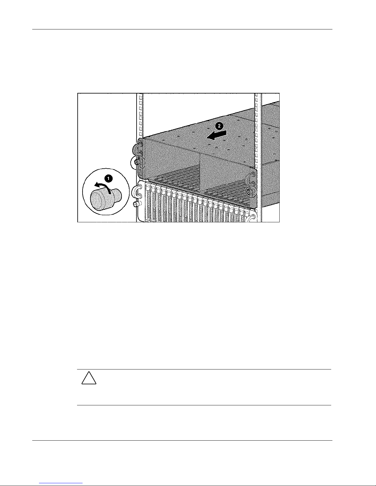
8. Loosen the thumbscrews on the front of the enclosure (1).
9. Remove the enclosure from the rack (2).
IMPORTANT: Pull the enclosure out using the handles. Pulling the enclosure by the thumbscrews
damages the thumbscrews.
Figure 2-11: Removing the enclosure from the rack
Reverse steps 1 through 9 to install the enclosure into the rack.
Opening the Access Door
To open the access door:
1. Power down each server blade. See the “Powering Down a Server Blade” section in this
chapter.
2. Power down the enclosure. See the “Powering Down the Enclosure” section in this
chapter.
3. Disconnect all cables and power cords from the AC power source.
4. Disconnect all cables and power cords from the enclosure rear panel.
5. Remove all server blades and server blade blanks. See the “Removing a Server Blade”
and the “Removing a Server Blade Blank” sections in this chapter.
CAUTION: Integrated Administrator security settings are assigned to server blade bays, not
to server blades. If server blades change locations within the enclosure, Integrated
Administrator settings must also be adjusted to ensure accurate security. Refer to the HP
ProLiant BL e-Class Integrated Administrator User Guide for more information on security
settings.
6. Remove the enclosure from the rack. See the “Removing the Enclosure from the Rack”
section in this chapter.
2-16 HP ProLiant BL e-Class System Maintenance and Service Guide
HP CONFIDENTIAL Codename: Kerr Part Number: 249066-004 Last Saved On: 5/12/03 3:00 PM
Page 32
Removal and Replacement Procedures
7. Place the enclosure on a level, nonconductive surface.
WARNING: A risk of injury from high current-electrical energy exists. Be sure the
power to the enclosure is completely shut off before opening the access door.
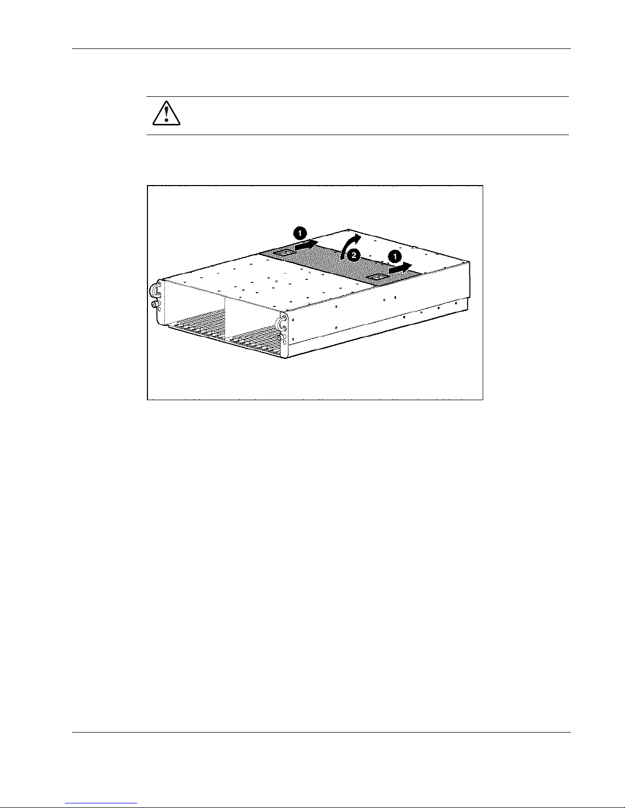
8. Release the latches on the access door (1).
9. Open the access door (2).
Figure 2-12: Opening the access door
Non-Hot-Plug Procedures
Before removing or replacing non-hot-plug components, you must power down the server
blade enclosure completely. Non-hot-plug components in the ProLiant BL e-Class system
include:
Fan cage •
•
Fan backplane assembly
•
Interconnect tray
•
Integrated Administrator module
•
Enclosure status assembly
•
DIMM
HP ProLiant BL e-Class System Maintenance and Service Guide 2-17
HP CONFIDENTIAL Codename: Kerr Part Number: 249066-004 Last Saved On: 5/12/03 3:00 PM
Page 33
Removal and Replacement Procedures
Hard drive •
• • Server blade battery
Center wall assembly
Fan Cage
To remove the fan cage:
1. Power down each server blade. See the “Powering Down a Server Blade” section in this
chapter.
2. Power down the enclosure. See the “Powering Down the Enclosure” section in this
chapter.
3. Disconnect all cables and power cords from the AC power source.
4. Disconnect all cables and power cords from the enclosure rear panel.
5. Remove all server blades. See the “Removing a Server Blade” section in this chapter.
CAUTION: Integrated Administrator security settings are assigned to server blade bays, not
to server blades. If server blades change locations within the enclosure, Integrated
Administrator settings must also be adjusted to ensure accurate security. Refer to the HP
ProLiant BL e-Class Integrated Administrator User Guide for more information on security
settings.
6. Remove both hot-plug power supplies. See the “Hot-Plug Power Supplies” section in this
chapter.
7. Remove the interconnect tray. See the “Removing the Interconnect Tray” section in this
chapter.
8. Remove the enclosure from the rack. See the “Removing the Server Blade Enclosure
from the Rack” section in this chapter.
9. Place the enclosure on a level, nonconductive surface.
2-18 HP ProLiant BL e-Class System Maintenance and Service Guide
HP CONFIDENTIAL Codename: Kerr Part Number: 249066-004 Last Saved On: 5/12/03 3:00 PM
Page 34
Removal and Replacement Procedures
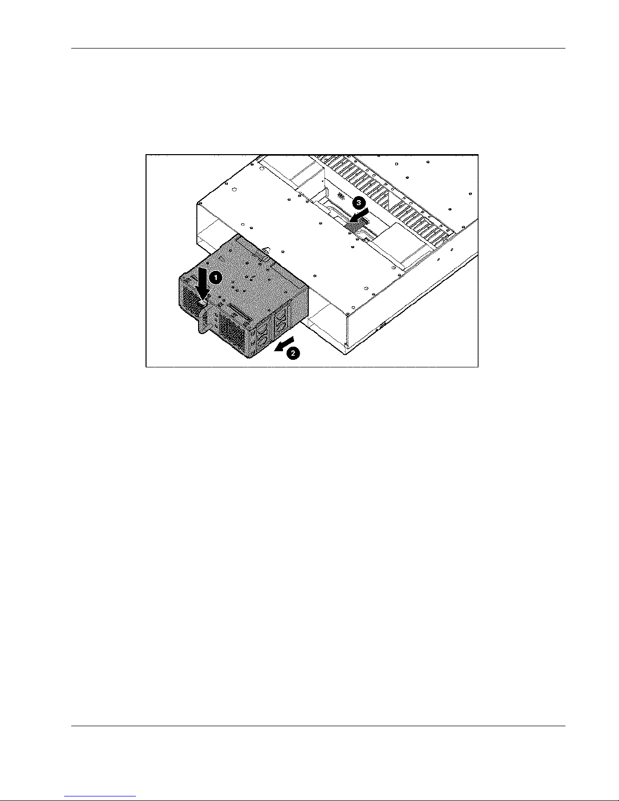
10. Press the fan cage release latch (1).
11. Pull the fan cage out of the enclosure until it locks in the open position (2).
12. Open the access door. See the “Opening the Access Door” section in this chapter.
13. Disconnect the fan cable from the power backplane (3).
Figure 2-13: Disconnecting the fan cable from the power backplane
HP ProLiant BL e-Class System Maintenance and Service Guide 2-19
HP CONFIDENTIAL Codename: Kerr Part Number: 249066-004 Last Saved On: 5/12/03 3:00 PM
Page 35
Removal and Replacement Procedures
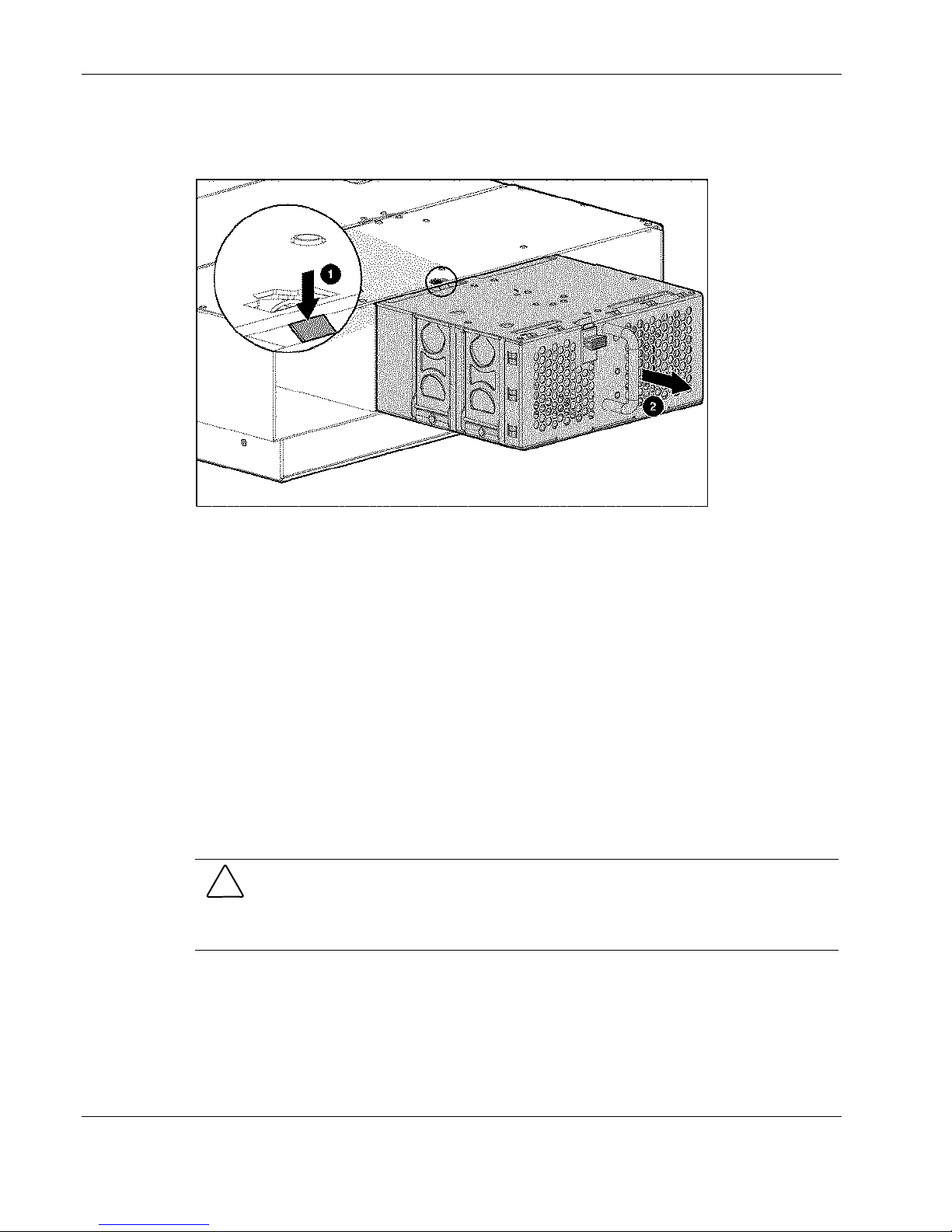
14. Press the fan cage removal latch on top of the fan cage (1).
15. Remove the fan cage from the enclosure (2).
Figure 2-14: Removing the fan cage from the enclosure
Reverse steps 1 through 15 to replace the fan cage.
Fan Backplane Assembly
To remove the fan backplane assembly:
1. Power down each server blade. See the “Powering Down a Server Blade” section in this
chapter.
2. Power down the enclosure. See the “Powering Down the Enclosure” section in this
chapter.
3. Disconnect all cables and power cords from the AC power source.
4. Disconnect all cables and power cords from the enclosure rear panel.
5. Remove all server blades. See the “Removing a Server Blade” section in this chapter.
CAUTION: Integrated Administrator security settings are assigned to server blade bays, not
to server blades. If server blades change locations within the enclosure, Integrated
Administrator settings must also be adjusted to ensure accurate security. Refer to the HP
ProLiant BL e-Class Integrated Administrator User Guide for more information on security
settings.
6. Remove both hot-plug power supplies. See the “Hot-Plug Power Supplies” section in this
chapter.
7. Remove the interconnect tray. See the “Removing the Interconnect Tray” section in this
chapter.
2-20 HP ProLiant BL e-Class System Maintenance and Service Guide
HP CONFIDENTIAL Codename: Kerr Part Number: 249066-004 Last Saved On: 5/12/03 3:00 PM
Page 36
Removal and Replacement Procedures
8. Remove the enclosure from the rack. See the “Removing the Server Blade Enclosure
from the Rack” section in this chapter.
9. Place the enclosure on a level, nonconductive surface.
10. Open the access door. See the “Opening the Access Door” section in this chapter.
11. Disconnect the fan cable from the power backplane.
12. Remove the fan cage. See the “Fan Cage” section in this chapter.
13. Remove the hot-plug fans. See the “Hot-Plug Fans” section in this chapter.
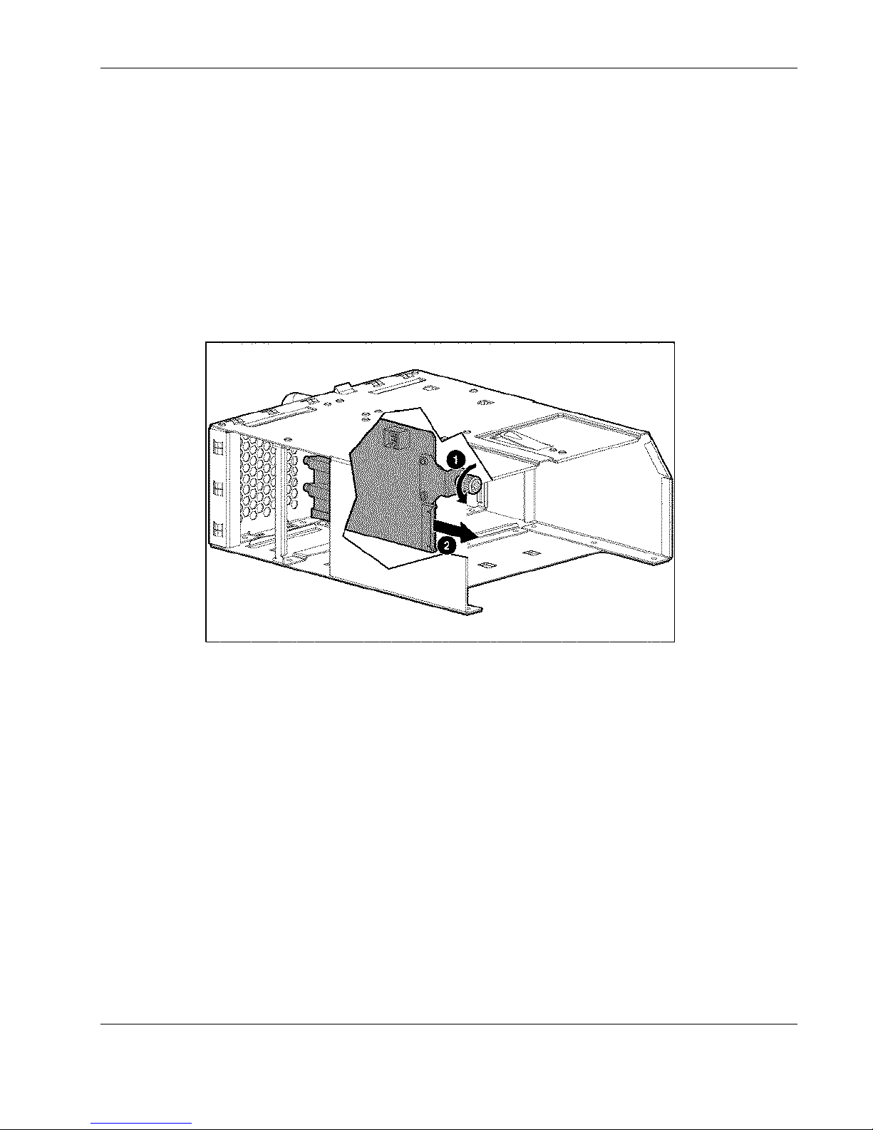
14. Loosen the thumbscrew at the back of the fan cage (1).
15. Remove the fan backplane assembly from the fan cage (2).
Figure 2-15: Removing the fan backplane assembly
Reverse steps 1 through 15 to replace the fan backplane assembly.
Integrated Administrator Module
The Integrated Administrator module removal procedure is the same for all three types of
interconnect trays.
To remove the Integrated Administrator module:
1. Power down each server blade. See the “Powering Down a Server Blade” section in this
chapter.
2. Power down the enclosure. See the “Powering Down the Enclosure” section in this
chapter.
3. Disconnect all cables and power cords from the AC power source.
4. Disconnect all cables and power cords from the enclosure rear panel.
HP ProLiant BL e-Class System Maintenance and Service Guide 2-21
HP CONFIDENTIAL Codename: Kerr Part Number: 249066-004 Last Saved On: 5/12/03 3:00 PM
Page 37
Removal and Replacement Procedures
5. Remove both hot-plug power supplies. See the “Hot-Plug Power Supplies” section in this
chapter.
6. Remove the interconnect tray from the enclosure. See the “Interconnect Tray” section in
this chapter.
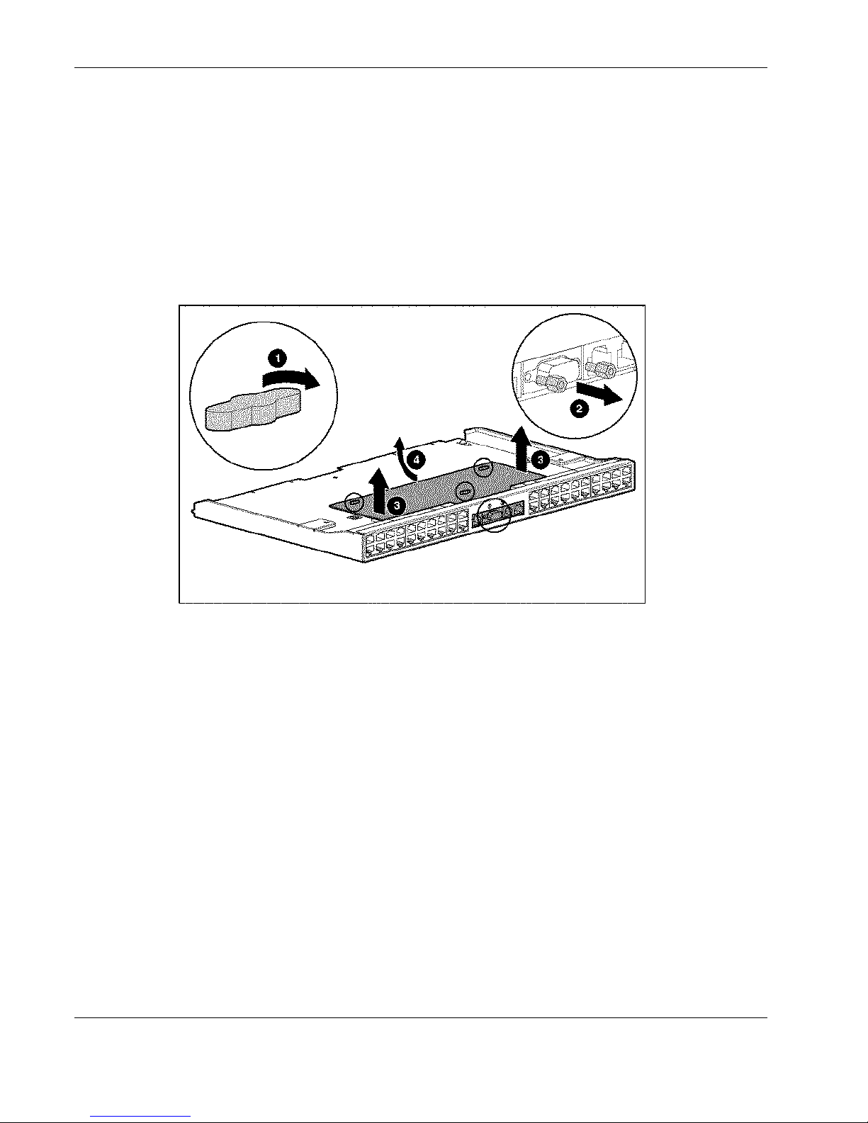
7. Rotate the quarter-turn posts on the Integrated Administrator module 90 degrees (1).
8. Remove the two screw locks with the tool provided in your spares kit (2).
9. Lift the Integrated Administrator module off the anchor pins (3).
10. Remove the Integrated Administrator module from the interconnect tray (4).
Figure 2-16: Removing the Integrated Administrator module from
the interconnect tray
Reverse steps 1 through 10 to replace the Integrated Administrator module.
Enclosure Status Assembly
To remove the enclosure status assembly:
1. Power down each server blade. See the “Powering Down a Server Blade” section in this
chapter.
2. Power down the enclosure. See the “Powering Down the Enclosure” section in this
chapter.
3. Disconnect all cables and power cords from the AC power source.
4. Disconnect all cables and power cords from the enclosure rear panel.
5. Remove all server blades and server blade blanks. See the “Removing a Server Blade”
and the “Removing a Server Blade Blank” sections in this chapter.
2-22 HP ProLiant BL e-Class System Maintenance and Service Guide
HP CONFIDENTIAL Codename: Kerr Part Number: 249066-004 Last Saved On: 5/12/03 3:00 PM
Page 38
Removal and Replacement Procedures
CAUTION: Integrated Administrator security settings are assigned to server blade bays, not
to server blades. If server blades change locations within the enclosure, Integrated
Administrator settings must also be adjusted to ensure accurate security. Refer to the HP
ProLiant BL e-Class Integrated Administrator User Guide for more information on security
settings.
6. Remove both hot-plug power supplies. See the “Hot-Plug Power Supplies” section in this
chapter.
7. Remove the interconnect tray from the enclosure. See the “Interconnect Tray” section in
this chapter.
8. Remove the enclosure from the rack. See the “Removing the Enclosure from the Rack”
section in this chapter.
9. Place the enclosure on a level, nonconductive surface.
10. Open the access door. See the “Opening the Access Door” section in this chapter.
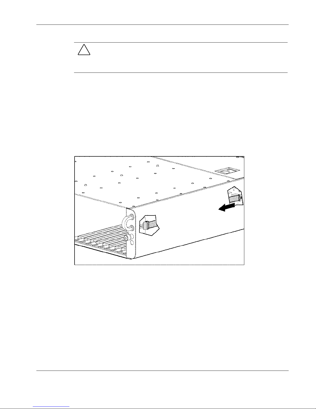
11. Disconnect the enclosure status cable from the server blade backplane.
Figure 2-17: Disconnecting the enclosure status cable from the
server blade backplane
HP ProLiant BL e-Class System Maintenance and Service Guide 2-23
HP CONFIDENTIAL Codename: Kerr Part Number: 249066-004 Last Saved On: 5/12/03 3:00 PM
Page 39
Removal and Replacement Procedures
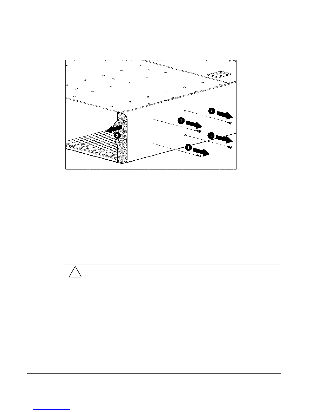
12. Remove the screws securing the enclosure status assembly in the enclosure (1).
13. Remove the enclosure status assembly from the enclosure (2).
Figure 2-18: Removing the enclosure status assembly from the
enclosure
DIMMs
Reverse steps 1 through 13 to replace the enclosure status assembly.
Before removing or replacing a DIMM from a server blade:
1. Power down the server blade. See the “Powering Down a Server Blade” section in this
chapter.
2. Remove the server blade from the enclosure. See the “Removing a Server Blade from the
Enclosure” section in this chapter.
CAUTION: Integrated Administrator security settings are assigned to server blade bays, not
to server blades. If server blades change locations within the enclosure, Integrated
Administrator settings must also be adjusted to ensure accurate security. Refer to the HP
ProLiant BL e-Class Integrated Administrator User Guide for more information on security
settings.
3. Place the server blade on a level, nonconductive surface.
To remove a DIMM:
1. Release the latches on each side of the DIMM slot 1 (1).
2. Remove the DIMM from the server blade (2).
2-24 HP ProLiant BL e-Class System Maintenance and Service Guide
HP CONFIDENTIAL Codename: Kerr Part Number: 249066-004 Last Saved On: 5/12/03 3:00 PM
Page 40
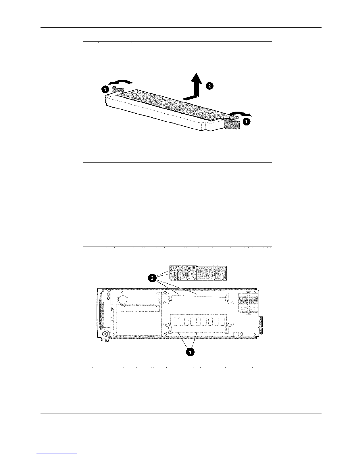
Figure 2-19: Removing a DIMM
To replace a DIMM:
Removal and Replacement Procedures
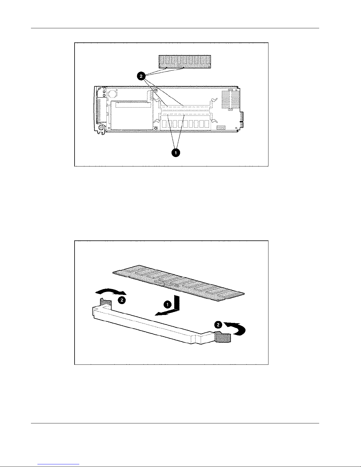
1. Locate the DIMM socket keys on the server blade:
— DIMM socket 1 keys (1)
— DIMM socket 2 keys (2)
IMPORTANT: DIMMs are installed inverted from one another. If the labels on DIMM 1 are face-up, the
labels on DIMM 2 are probably face-down.
Figure 2-20: DIMM socket keys for the ProLiant BL10e server blade
HP ProLiant BL e-Class System Maintenance and Service Guide 2-25
HP CONFIDENTIAL Codename: Kerr Part Number: 249066-004 Last Saved On: 5/12/03 3:00 PM
Page 41
Removal and Replacement Procedures
Figure 2-21: DIMM socket keys for the ProLiant BL10e G2 server
blade
IMPORTANT: Each server blade ships with one DIMM installed.
2. Install DIMM 1:
a. Insert the DIMM into the DIMM slot (1) until the latches snap into place.
b. Press the latches towards each other to ensure that they are fully seated (2).
Figure 2-22: Replacing a DIMM
3. Repeat step 2 to install a second DIMM into DIMM slot 2.
2-26 HP ProLiant BL e-Class System Maintenance and Service Guide
HP CONFIDENTIAL Codename: Kerr Part Number: 249066-004 Last Saved On: 5/12/03 3:00 PM
Page 42
Hard Drive Assembly
IMPORTANT: Hard drives and processors for the ProLiant BL e-Class server blade are model specific.
For more information, refer to the QuickSpecs on the HP website.
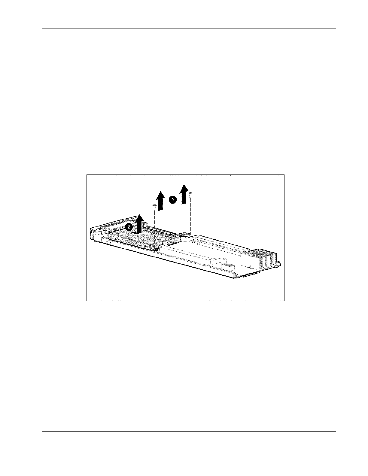
To remove the hard drive assembly from a ProLiant BL e-Class server blade:
1. Power down the server blade. See the “Powering Down a Server Blade” section in this
chapter.
2. Remove the server blade from the enclosure. See the “Removing a Server Blade” section
in this chapter.
3. Place on a level, nonconductive surface.
4. Using a Torx T-15 tool, remove the screws holding the hard drive assembly to the server
blade (1).
5. Slide the hard drive assembly toward the processor, and lift it from the server blade (2).
Removal and Replacement Procedures
Figure 2-23: Removing the hard drive assembly from a server blade
NOTE: Figure 2-23 shows the ProLiant BL10e server blade.
Reverse steps 1 through 5 to replace a hard drive assembly.
Server Blade Battery
To remove a server blade battery:
1. Power down the server blade. See the “Powering Down a Server Blade” section in this
chapter.
2. Remove the server blade from the enclosure. See the “Removing a Server Blade from the
Enclosure” section in this chapter.
HP ProLiant BL e-Class System Maintenance and Service Guide 2-27
HP CONFIDENTIAL Codename: Kerr Part Number: 249066-004 Last Saved On: 5/12/03 3:00 PM
Page 43
Removal and Replacement Procedures
3. Place the server blade on a level, nonconductive surface.
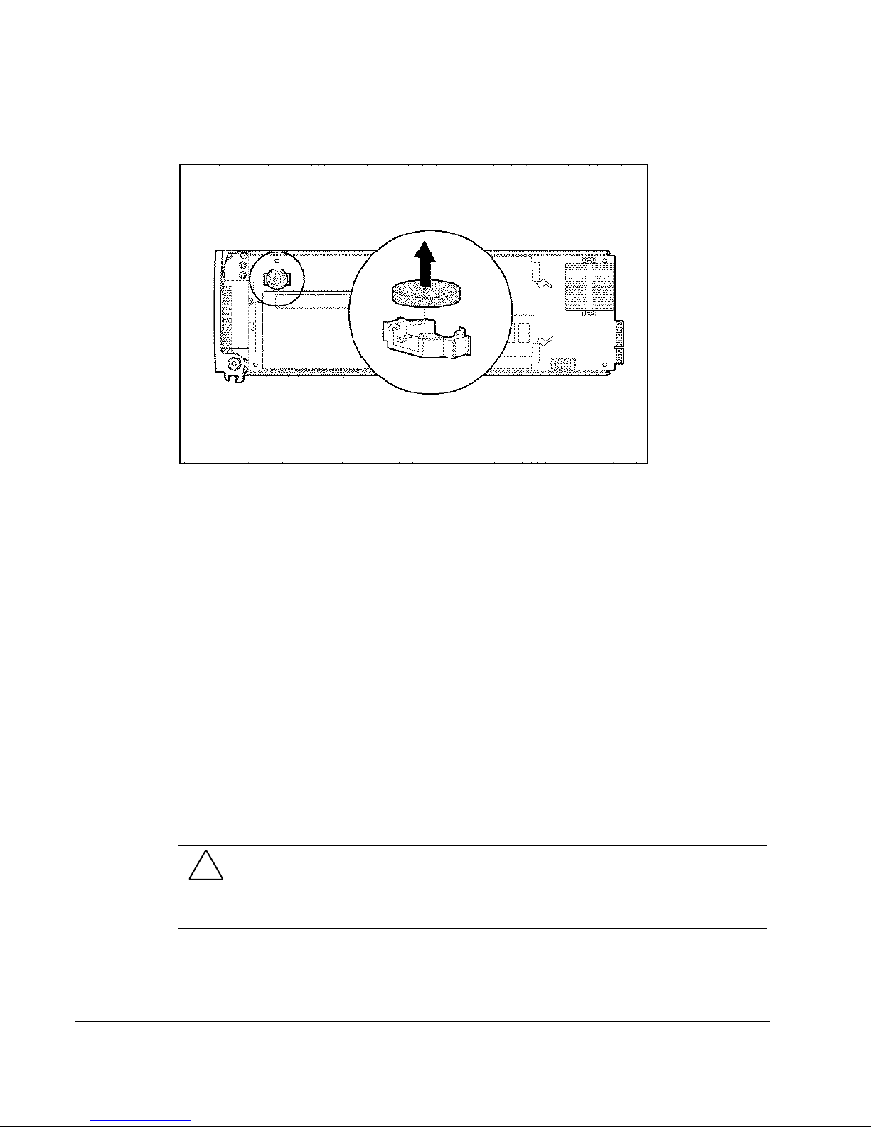
4. Locate and remove the battery on the server blade.
Figure 2-24: Locating and removing the battery
NOTE: Figure 2-24 shows the ProLiant BL10e server blade.
Reverse steps 1 through 4 to replace the battery.
Center Wall Assembly
To remove the center wall assembly:
1. Power down each server blade. See the “Powering Down a Server Blade” section in this
chapter.
2. Power down the enclosure. See the “Powering Down the Enclosure” section in this
chapter.
3. Disconnect all cables and power cords from the AC power source.
4. Disconnect all cables and power cords from the enclosure rear panel.
5. Remove all server blades and server blade blanks. See the “Removing a Server Blade”
and the “Removing a Server Blade Blank” sections in this chapter.
CAUTION: Integrated Administrator security settings are assigned to server blade bays, not
to server blades. If server blades change locations within the enclosure, Integrated
Administrator settings must also be adjusted to ensure accurate security. Refer to the HP
ProLiant BL e-Class Integrated Administrator User Guide for more information on security
settings.
6. Remove both hot-plug power supplies. See the “Hot-Plug Power Supplies” section in this
chapter.
2-28 HP ProLiant BL e-Class System Maintenance and Service Guide
HP CONFIDENTIAL Codename: Kerr Part Number: 249066-004 Last Saved On: 5/12/03 3:00 PM
Page 44
Removal and Replacement Procedures
7. Remove the interconnect tray from the enclosure. See the “Interconnect Tray” section in
this chapter.
8. Remove the enclosure from the rack. See the “Removing the Server Blade Enclosure
from the Rack” section in this chapter.
9. Place the enclosure on a level, nonconductive surface.
10. Open the access door. See the “Opening the Access Door” section in this chapter.
11. Disconnect the fan cable from the power backplane. See the “Fan Backplane Assembly”
section in this chapter.
12. Disconnect the enclosure status cable from the server blade backplane. See the
“Enclosure Status Assembly” section in this chapter.
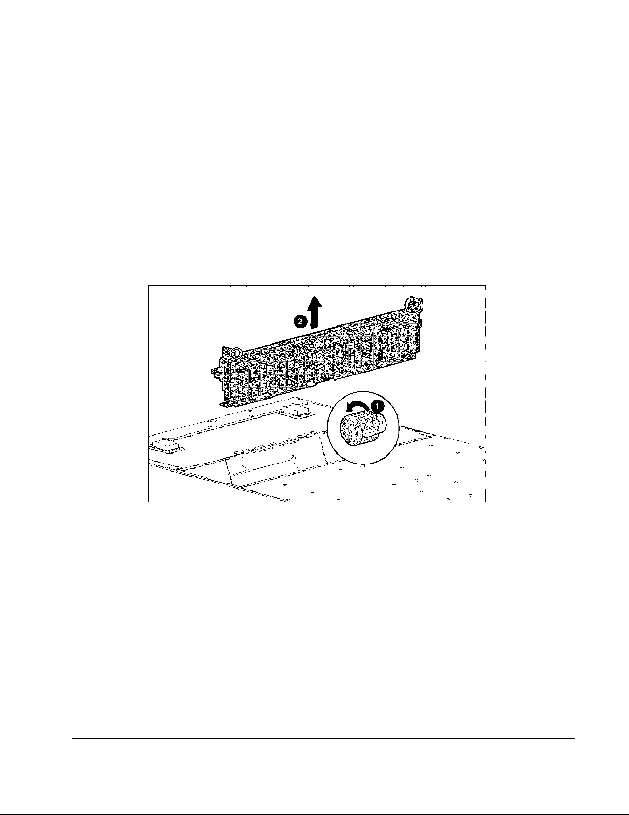
13. Loosen the thumbscrews on the center wall (1).
14. Remove the center wall assembly from the enclosure (2).
Figure 2-25: Removing the center wall assembly from the enclosure
Reverse steps 1 through 14 to replace the center wall assembly.
Swapping the Interconnect Tray
To swap the existing interconnect tray with a replacement interconnect tray:
1. Remove the interconnect tray from the enclosure. See the “Removing the Interconnect
Tray” sections in this chapter.
2. Remove the Integrated Administrator module from the interconnect tray. See the
“Integrated Administrator Module” section in this chapter.
3. Place the replacement interconnect tray on a level, nonconductive surface.
HP ProLiant BL e-Class System Maintenance and Service Guide 2-29
HP CONFIDENTIAL Codename: Kerr Part Number: 249066-004 Last Saved On: 5/12/03 3:00 PM
Page 45
Removal and Replacement Procedures
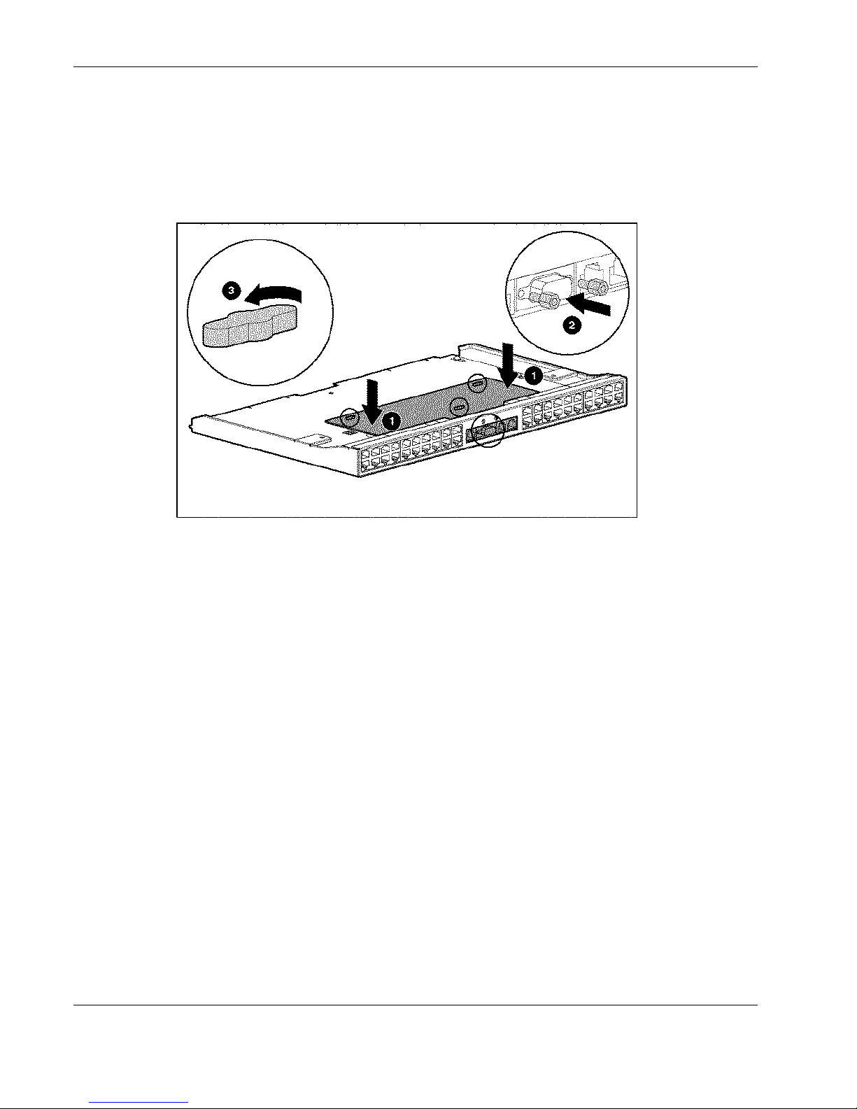
4. Position the Integrated Administrator module so that its holes are aligned with the anchor
pins of the replacement interconnect tray (1).
5. Replace the two screw locks with the tool provided in the spares kit (2).
6. Rotate the anchor pins 90 degrees to lock the Integrated Administrator module into
position (3).
Figure 2-26: Installing the Integrated Administrator module onto the
interconnect tray
7. Replace the interconnect tray. See the “Removing the Interconnect Tray” section in this
chapter.
2-30 HP ProLiant BL e-Class System Maintenance and Service Guide
HP CONFIDENTIAL Codename: Kerr Part Number: 249066-004 Last Saved On: 5/12/03 3:00 PM
Page 46

Diagnostic Tools
This chapter is an overview of hardware, software, and firmware diagnostic tools that are
available for configuring, monitoring, and managing ProLiant BL e-Class systems.
3
HP ProLiant BL e-Class System Maintenance and Service Guide 3-1
HP CONFIDENTIAL Codename: Kerr Part Number: 249066-004 Last Saved On: 5/12/03 3:04 PM
Page 47

Diagnostic Tools
Diagnostic Software and Firmware Tools
The ProLiant BL e-Class Integrated Administrator is a standard component of the HP
ProLiant BL e-Class system. The Integrated Administrator provides enclosure health, server
blade health, and remote server manageability. Integrated Administrator features are accessed
from any network-based client using a supported Web browser. In addition to other features,
Integrated Administrator provides keyboard and mouse capability for a server blade,
regardless of the state of the host operating system or host server blade.
Use the following tools to diagnose problems, test hardware, and monitor and manage
ProLiant BL e-Class system operations.
Table 3-1: Diagnostic Tools
Tool Description How to run the tool
ProLiant BL e-Class
Integrated Administrator
Automatic Server
Recovery-2 (ASR-2)
The ProLiant BL e-Class
Integrated Administrator is a
centralized management and
monitoring system for the
ProLiant BL e-Class enclosure
and server blades. The
Integrated Administrator acts as
a combination terminal server
and remote power controller,
enabling out-of-band, secure,
serial console connections to all
server blades in the enclosure.
ASR-2 automatically restarts a
server blade after a catastrophic
operating system failure.
With ASR-2, you have multiple
recovery options:
• Available Recovery
provides software error
recovery and environmental
recovery.
• Unattended Recovery logs
the error information to the
IML, resets the server
blade, and tries to restart
the operating system.
Refer to the HP ProLiant BL
e-Class Integrated
Administrated User Guide for
complete details.
Run the ROM-Based Setup
Utility and set ASR-2 to enable
this tool.
continued
3-2 HP ProLiant BL e-Class System Maintenance and Service Guide
HP CONFIDENTIAL Codename: Kerr Part Number: 249066-004 Last Saved On: 5/12/03 3:04 PM
Page 48

Table 3-1: Diagnostic Tools continued
Tool Description How to run the tool
Diagnostic Tools
Diagnostics Diagnostics tests and verifies
operation of HP hardware. If
Diagnostics finds a server
blade hardware failure, it
isolates the replaceable part, if
possible.
Insight Manager 7 Insight Manager 7 is a
client/server application used
to remotely manage HP
hardware in a network
environment. Insight Manager
reports server blade and server
blade enclosure hardware fault
conditions (both failure and
pre-failure) and collects data
for reporting and graphing.
Integrated Management Log
(IML)
The IML is a log of system
events such as system failures
or nonfatal error conditions.
View events in the IML from
within:
• Insight Manager 7
Access Diagnostics when
POST detects a system
configuration error. For a
complete list of POST error
messages, refer to the HP
Servers Troubleshooting
Guide. Diagnostics may be
downloaded onto a diskette
from the Rapid Deployment CD
or from the following website:
www.compaq.com/support/files
For more information on
viewing and printing the event
list, refer to the Management
CD or the Insight Manager
User Guide.
The IML requires operating
system management drivers.
Refer to the Rapid
Deployment CD for instructions
on installing the appropriate
drivers.
• Operating system-specific
IML utilities
continued
HP ProLiant BL e-Class System Maintenance and Service Guide 3-3
HP CONFIDENTIAL Codename: Kerr Part Number: 249066-004 Last Saved On: 5/12/03 3:04 PM
Page 49

Diagnostic Tools
Table 3-1: Diagnostic Tools continued
Tool Description How to run the tool
ROM-Based Setup Utility
(RBSU)
ROMPaq Utility The ROMPaq Utility checks the
RBSU configures the hardware
installed in or connected to the
server blade. Specifically, it can:
• Store configuration
• Manage memory installation,
• Assist in installing an
• Configure connectors and
system and provides a choice of
available ROM revisions and
controller firmware.
Hardware Diagnostic Tools
The HP ProLiant BL e-Class system offers the following server blade and server blade
enclosure hardware diagnostic tools.
information in nonvolatile
memory.
processor upgrades, network
interface cards, and mass
storage devices.
operating system.
IRQs, if required.
Attach a keyboard to the server
blade using the diagnostic
adapter.
Run RBSU by pressing the F9
key during POST.
Download this utility from the
following website:
http://welcome.hp.com/country/u
s/eng/support.html
Diagnostic Adapter
Use the diagnostic adapter to attach peripheral devices to any individual server blade for local
server blade diagnosis and management. See Chapter 4, “Connectors, Switches, and LEDs”
for the location of diagnostic adapter connectors.
IMPORTANT: You can hot-add peripheral devices using the diagnostic adapter if the devices support
hot-plug capability.
To install the diagnostic adapter:
1. Power down the server blade. See the “Powering Down a Server Blade” section in
Chapter 2, “Removal and Replacement Procedures.”
3-4 HP ProLiant BL e-Class System Maintenance and Service Guide
HP CONFIDENTIAL Codename: Kerr Part Number: 249066-004 Last Saved On: 5/12/03 3:04 PM
Page 50
Diagnostic Tools
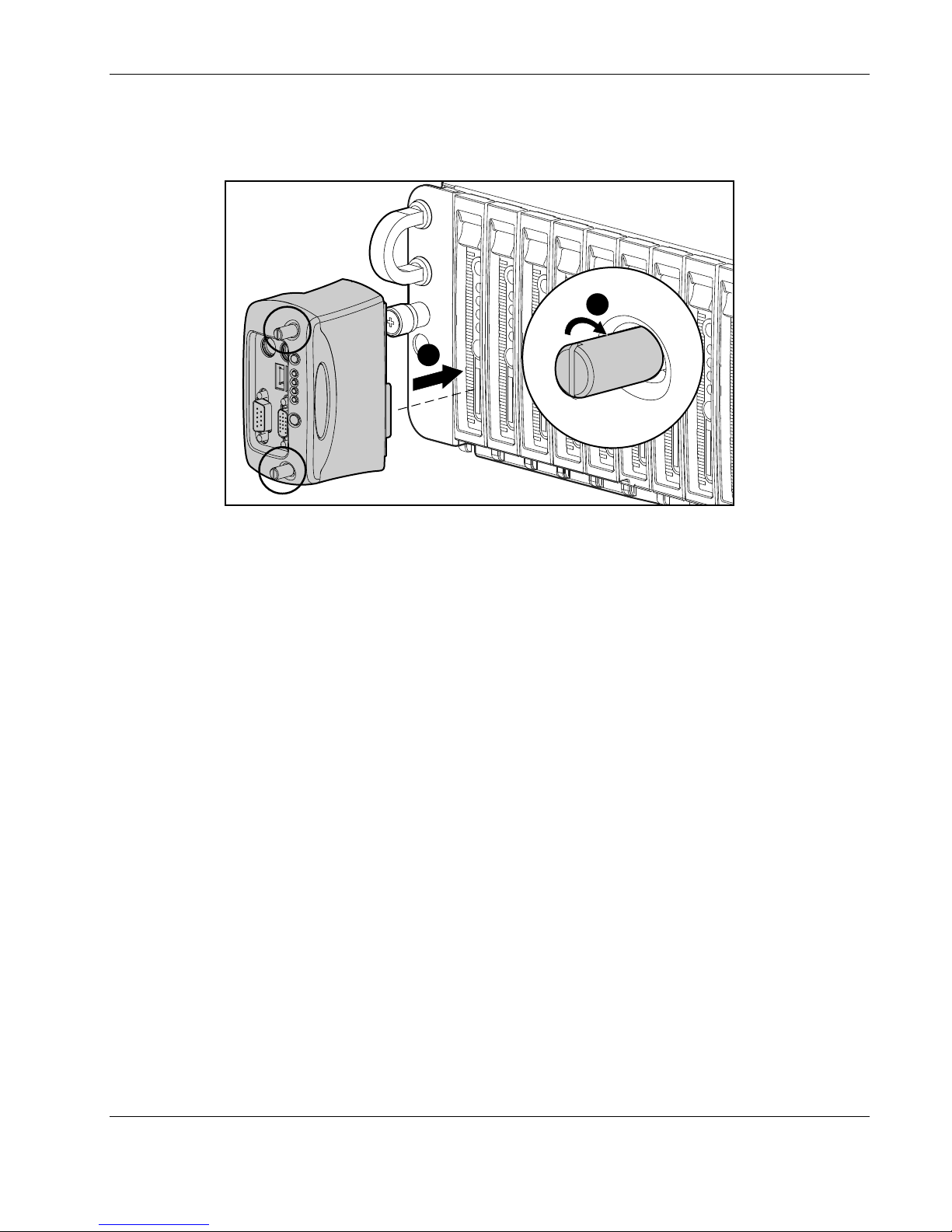
2. Plug the diagnostic adapter into the diagnostic connector on the server blade (1).
3. Tighten the thumbscrews securing the diagnostic adapter in place (2).
2
1
Figure 3-1: Installing a diagnostic adapter
4. Power up the server blade.
IMPORTANT: Because PS/2 devices do not support hot-plug technology, restart the server blade after
attaching the diagnostic adapter. USB devices are hot-plug supported and do not require restarting the
server blade after attachment.
HP ProLiant BL e-Class System Maintenance and Service Guide 3-5
HP CONFIDENTIAL Codename: Kerr Part Number: 249066-004 Last Saved On: 5/12/03 3:04 PM
Page 51

Diagnostic Tools
Null-Modem Cable Pin-Out
If you are cabling a serial device (such as a laptop computer) to the console connector on the
Integrated Administrator, be sure that you use a null-modem cable (provided with the
enclosure) and not a straight-through cable. Use the following table to determine the
specifications of this cable.
Table 3-2: Cable Pin-Out for a Null-Modem Cable
Signal Name EM PIN DB-9 PIN DB-25 PIN
TxD 3 2 3
RxD 2 3 2
RTS 7 8 5
CTS 8 7 4
GND 5 5 7
DSR 6 4 20
CD 1 4 20
DTR 4 1 & 6 6 & 8
3-6 HP ProLiant BL e-Class System Maintenance and Service Guide
HP CONFIDENTIAL Codename: Kerr Part Number: 249066-004 Last Saved On: 5/12/03 3:04 PM
Page 52

This chapter explains the location and function of system connectors, system switches, and
internal and external LEDs.
Connectors
The figures and tables on the following pages show connector locations on the
ProLiant BL e-Class server blades and ProLiant BL e-Class server blade
enclosures.
Enclosure Connectors
This section explains the location and function of rear panel connectors associated with the
ProLiant C-GbE Interconnect Switch, RJ-21 patch panel, and RJ-45 patch panel interconnect
trays.
4
Connectors, Switches, and LEDs
HP ProLiant BL e-Class System Maintenance and Service Guide 4-1
HP CONFIDENTIAL Codename: Kerr Part Number: 249066-004 Last Saved On: 5/12/03 3:07 PM
Page 53
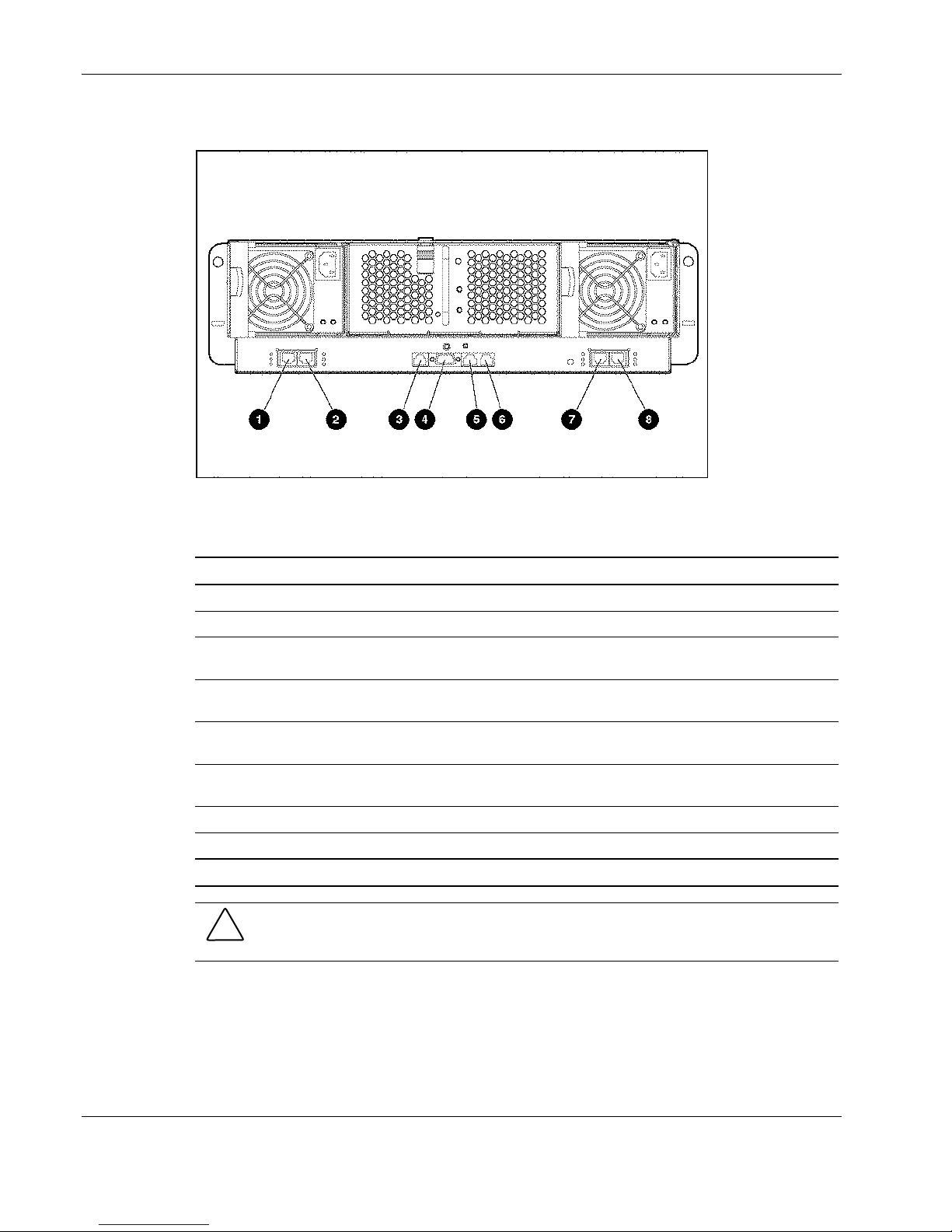
Connectors, Switches, and LEDs
ProLiant C-GbE Interconnect Switch Connectors
Figure 4-1: ProLiant C-GbE Interconnect Switch connectors
Table 4-1: ProLiant C-GbE Interconnect Switch Connectors
Item Description Location
1 Gigabit Ethernet port 26 connector on switch B Interconnect switch
2 Gigabit Ethernet port 25 connector on switch B Interconnect switch
3 Integrated Administrator management connector
(10/100 Ethernet)*
4 Integrated Administrator console connector (serial)* Integrated Administrator
5 Enclosure link (reserved for future use)* Integrated Administrator
6 Enclosure link (reserved for future use)* Integrated Administrator
7 Gigabit Ethernet port 26 connector on switch A Interconnect switch
8 Gigabit Ethernet port 25 connector on switch A Interconnect switch
* These items denote connectors for the Integrated Administrator module.
Integrated Administrator
module
module
module
module
CAUTION: See QuickSpecs for supported uses of the enclosure link (RJ-45) connectors on
the Integrated Administrator module. Connecting an unsupported external device to the
enclosure link (RJ-45) connecters may damage your external device.
4-2 HP ProLiant BL e-Class System Maintenance and Service Guide
HP CONFIDENTIAL Codename: Kerr Part Number: 249066-004 Last Saved On: 5/12/03 3:07 PM
Page 54
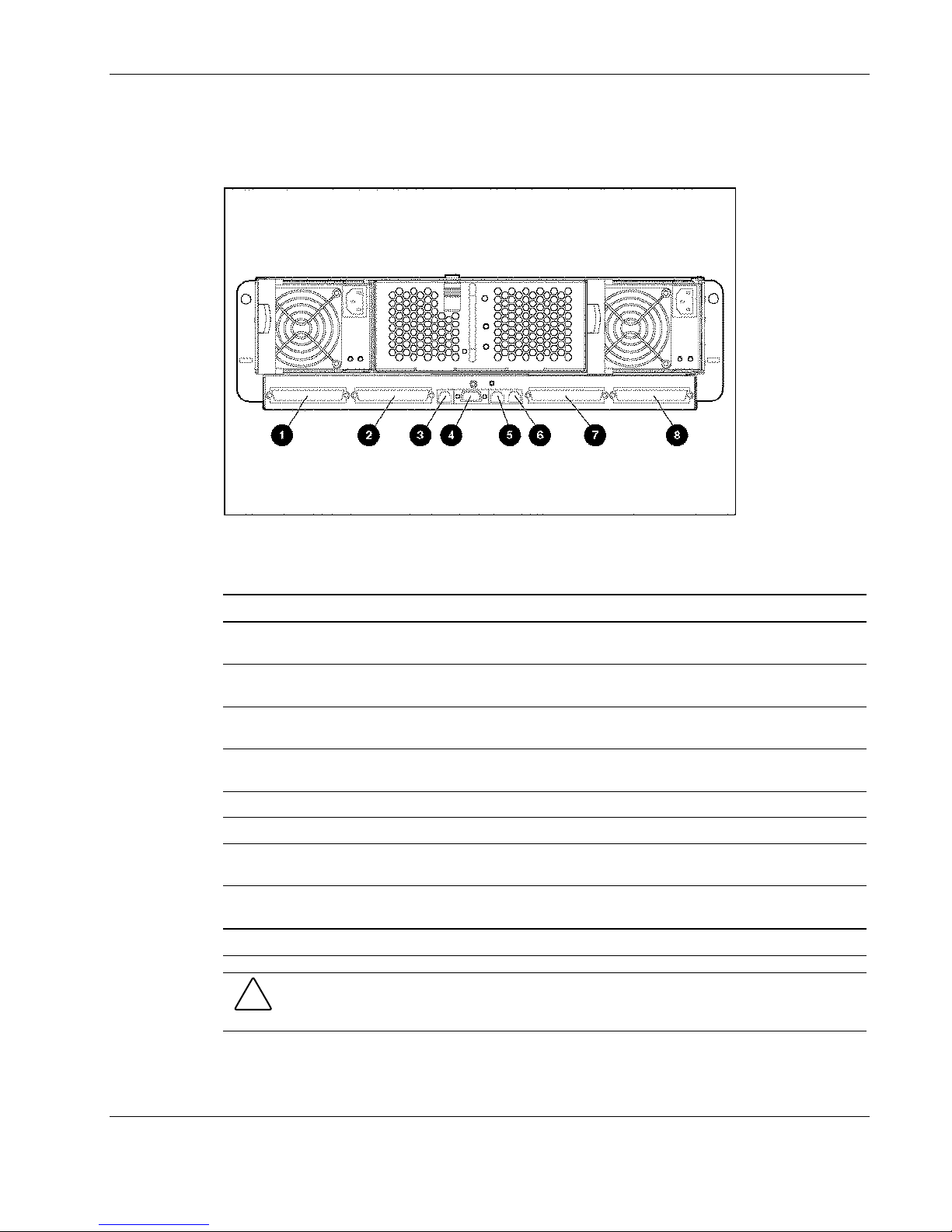
RJ-21 Patch Panel Connectors
Use Figure 4-2 and Table 4-2 to identify the RJ-21 patch panel connectors.
Figure 4-2: RJ-21 patch panel connectors
Connectors, Switches, and LEDs
Table 4-2: RJ-21 Patch Panel Connectors
Item Description Location
1 RJ-21 connector for server blade bays 11-20
NIC 2
2 RJ-21 connector for server blade bays 1-10
NIC 2
3 Integrated Administrator management
connector (10/100 Ethernet)*
4 Integrated Administrator console connector
(serial)*
5 Enclosure link (reserved for future use)* Integrated Administrator module
6 Enclosure link (reserved for future use)* Integrated Administrator module
7 RJ-21 connector for server blade bays 11-20
NIC 1
8 RJ-21 connector for server blade bays 1-10
NIC 1
* These items denote connectors for the Integrated Administrator module.
RJ-21 patch panel
RJ-21 patch panel
Integrated Administrator module
Integrated Administrator module
RJ-21 patch panel
RJ-21 patch panel
CAUTION: See QuickSpecs for supported uses of the enclosure link (RJ-45) connectors on
the Integrated Administrator module. Connecting an unsupported external device to the
enclosure link (RJ-45) connecters may damage your external device.
HP ProLiant BL e-Class System Maintenance and Service Guide 4-3
HP CONFIDENTIAL Codename: Kerr Part Number: 249066-004 Last Saved On: 5/12/03 3:07 PM
Page 55
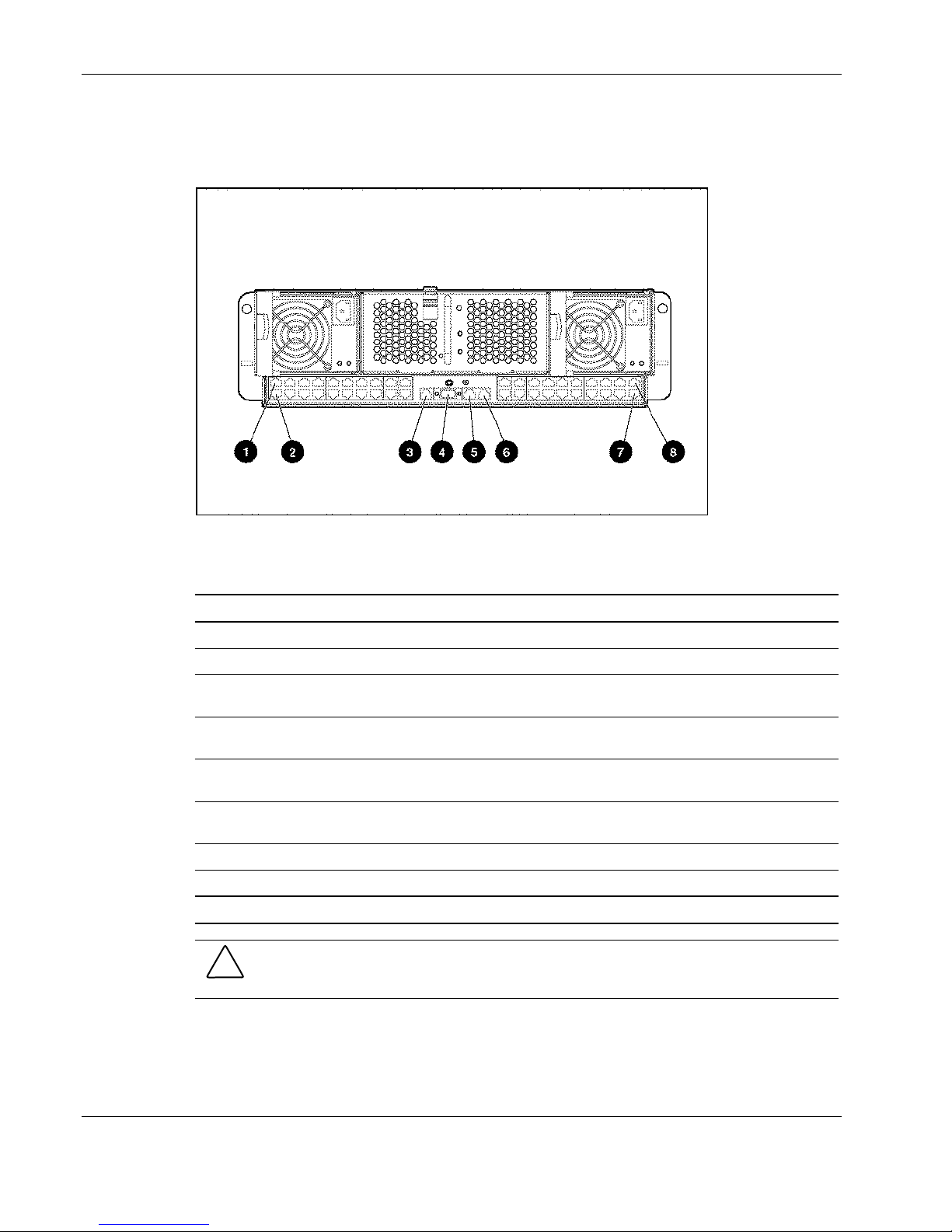
Connectors, Switches, and LEDs
RJ-45 Patch Panel Connectors
Use Figure 4-3 and Table 4-3 to identify the RJ-45 patch panel connectors.
Figure 4-3: RJ-45 patch panel connectors
Table 4-3: RJ-45 Patch Panel Connectors
Item Description Location
1 RJ-45 connector for server blade bay 20 NIC 1 RJ-45 patch panel
2 RJ-45 connector for server blade bay 20 NIC 2 RJ-45 patch panel
3 Integrated Administrator management connector
(10/100 Ethernet)*
4 Integrated Administrator console connector (serial)* Integrated Administrator
5 Enclosure link (reserved for future use)* Integrated Administrator
6 Enclosure link (reserved for future use)* Integrated Administrator
7 RJ-45 connector for server blade bay 1 NIC 1 RJ-45 patch panel
8 RJ-45 connector for server blade bay 1 NIC 2 RJ-45 patch panel
* These items denote connectors for the Integrated Administrator module.
Integrated Administrator
module
module
module
module
CAUTION: See QuickSpecs for supported uses of the enclosure link (RJ-45) connectors on
the Integrated Administrator module. Connecting an unsupported external device to the
enclosure link (RJ-45) connecters may damage your external device.
4-4 HP ProLiant BL e-Class System Maintenance and Service Guide
HP CONFIDENTIAL Codename: Kerr Part Number: 249066-004 Last Saved On: 5/12/03 3:07 PM
Page 56
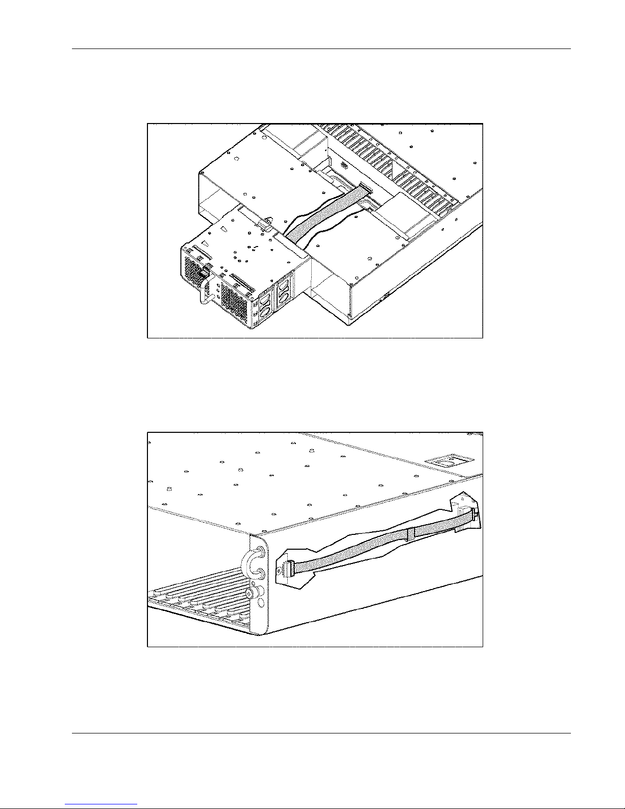
Fan Cable Connector
Use Figure 4-4 to identify the connector on the center wall assembly for the fan cable.
Figure 4-4: Fan cable connector on the center wall assembly
Connectors, Switches, and LEDs
Enclosure Status Cable Connector
Use Figure 4-5 to identify the connector on the server blade backplane for the enclosure
status cable.
Figure 4-5: Enclosure status cable connector on the server blade
backplane
HP ProLiant BL e-Class System Maintenance and Service Guide 4-5
HP CONFIDENTIAL Codename: Kerr Part Number: 249066-004 Last Saved On: 5/12/03 3:07 PM
Page 57
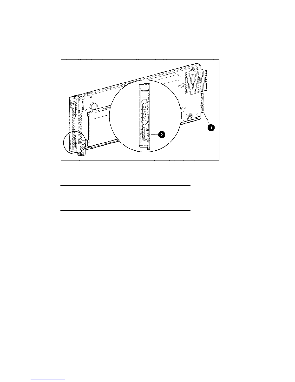
Connectors, Switches, and LEDs
Server Blade Connectors
Use Figure 4-6 and Table 4-4 to identify the connectors on each server blade.
Figure 4-6: Identifying the server blade connectors
Table 4-4: Server Blade Connectors
Item Description
1 Center wall assembly connectors
2 Diagnostic connector
4-6 HP ProLiant BL e-Class System Maintenance and Service Guide
HP CONFIDENTIAL Codename: Kerr Part Number: 249066-004 Last Saved On: 5/12/03 3:07 PM
Page 58
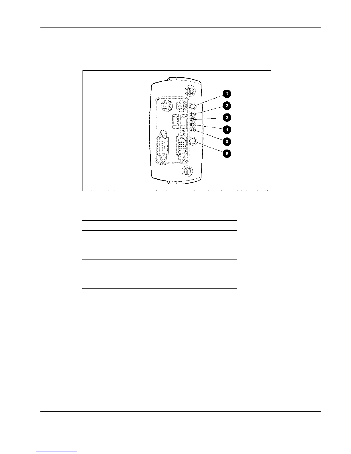
Diagnostic Adapter Connectors
Use Figure 4-7 and Table 4-5 to identify the connectors on the diagnostic adapter.
Figure 4-7: Diagnostic adapter connectors
Connectors, Switches, and LEDs
Table 4-5: Diagnostic Adapter Connectors
Item Description
1 Keyboard connector (PS/2)
2 Mouse connector (PS/2)
3 USB 2 connector
4 USB 1 connector
5 Serial connector
6 Video connector
HP ProLiant BL e-Class System Maintenance and Service Guide 4-7
HP CONFIDENTIAL Codename: Kerr Part Number: 249066-004 Last Saved On: 5/12/03 3:07 PM
Page 59
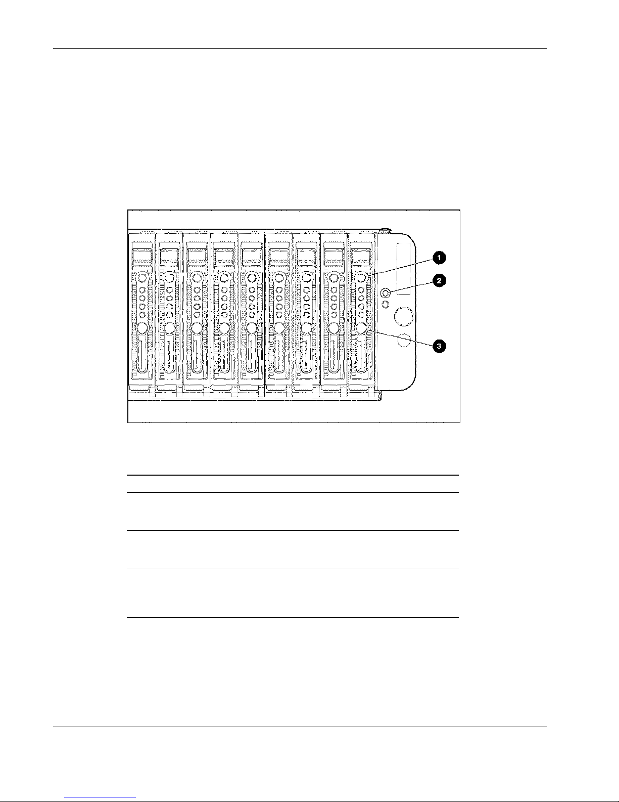
Connectors, Switches, and LEDs
Switches
With system switches, you can enable or disable certain settings or perform advanced
diagnostic procedures.
Front Panel Switches
Use Figure 4-8 and Table 4-6 to determine the location and function of the switches on the
front panel of the enclosure and server blade.
Figure 4-8: Server blade and enclosure front panel buttons
Table 4-6: Server Blade and Enclosure Front Panel Buttons
Item Description Function
1 Server blade unit
identification button
2 Enclosure unit identification
button
3 Server blade power button Powers up or down a server
Activates the unit identification
LED for easy server blade
identification
Activates the unit identification
LED for easy enclosure
identification
blade. (Hold down for 4 seconds
to perform an emergency
shutdown.)
4-8 HP ProLiant BL e-Class System Maintenance and Service Guide
HP CONFIDENTIAL Codename: Kerr Part Number: 249066-004 Last Saved On: 5/12/03 3:07 PM
Page 60
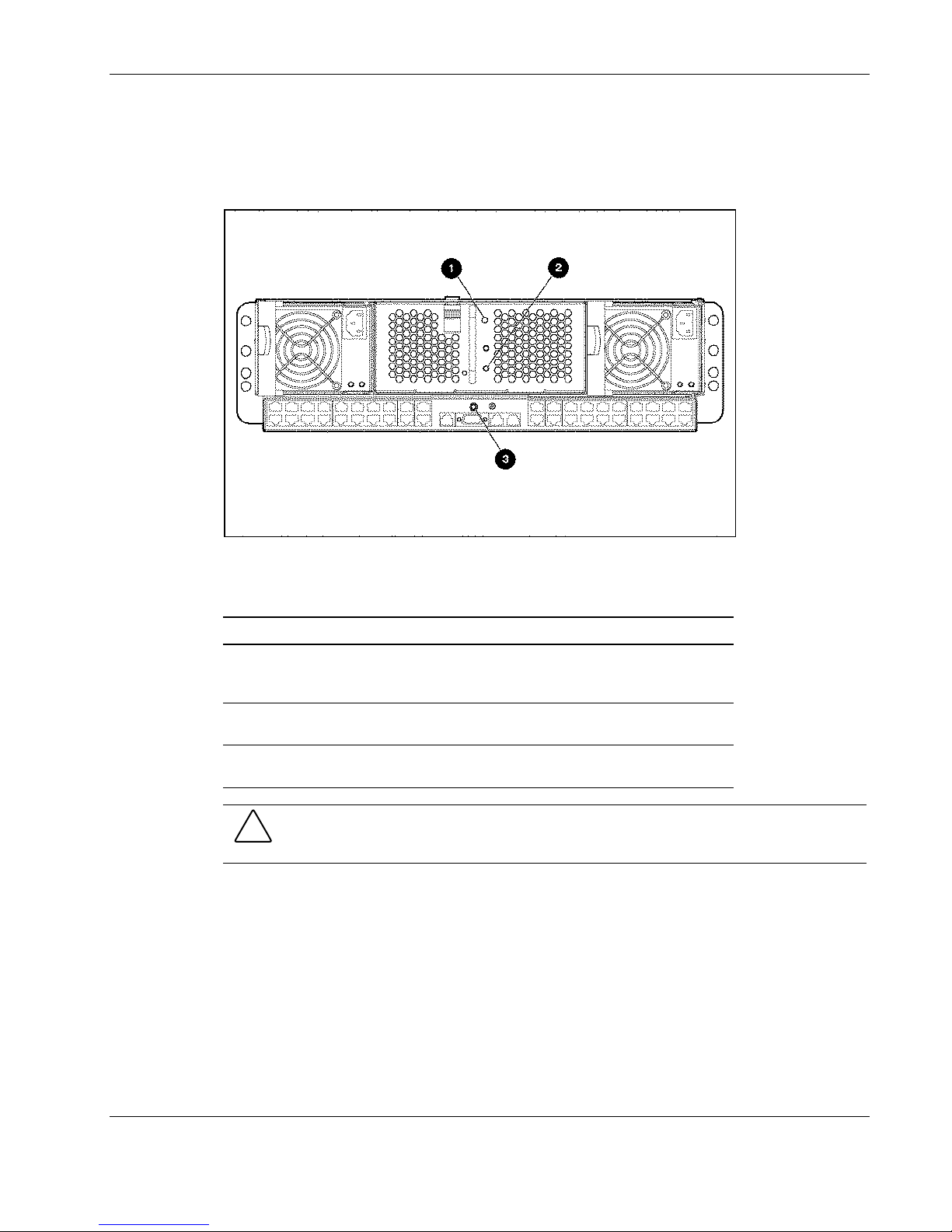
Rear Panel Switches
Use Figure 4-9 and Table 4-7 to determine the location and function of the buttons on the rear
panel of the enclosure.
Connectors, Switches, and LEDs
Figure 4-9: Enclosure rear panel buttons
Table 4-7: Enclosure Rear Panel Buttons
Item Description On/Off Function
1 Enclosure unit identification
button
2 Enclosure power button Powers the enclosure and all
3 Integrated Administrator
reset button
Activates the unit identification
LED for easy enclosure
identification
server blades up or down
Restarts the Integrated
Administrator
CAUTION: Pressing and holding the enclosure power button for 4 seconds causes an
emergency shutdown on the enclosure and all server blades, and may result in the loss of any
unsaved data on all server blades.
HP ProLiant BL e-Class System Maintenance and Service Guide 4-9
HP CONFIDENTIAL Codename: Kerr Part Number: 249066-004 Last Saved On: 5/12/03 3:07 PM
Page 61
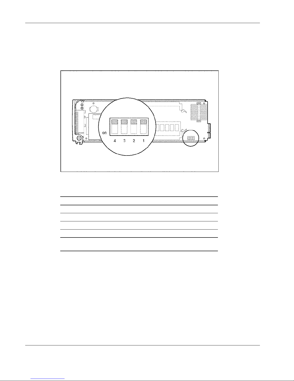
Connectors, Switches, and LEDs
Maintenance Switch
Each ProLiant BL e-Class server blade features an internal switch for user maintenance
(SW1). Use Figure 4-10 and Table 4-8 to determine the location and function of the server
blade maintenance switches.
Figure 4-10: Maintenance switch
Table 4-8: Maintenance Switch
Switch Default Function
S1 Off Reserved*
S2 Off Configuration lock
S3 Off Password clear
S4 Off Invalidate configuration*
* To access redundant ROM, set S1 and S4 to on. Refer to the HP ProLiant
BL e-Class System Setup and Installation Guide.
4-10 HP ProLiant BL e-Class System Maintenance and Service Guide
HP CONFIDENTIAL Codename: Kerr Part Number: 249066-004 Last Saved On: 5/12/03 3:07 PM
Page 62
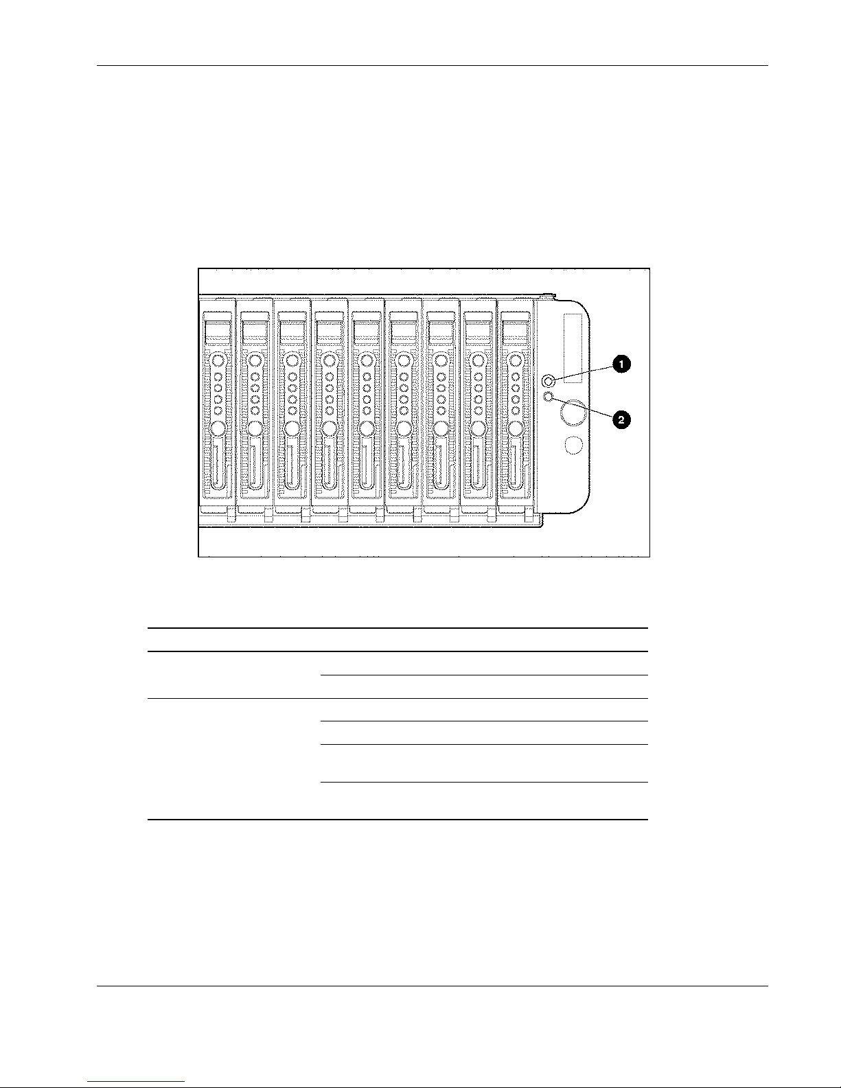
LEDs
The figures and tables on the following pages show the location and function of LEDs
associated with the ProLiant BL e-Class system.
Enclosure Front Panel LEDs
Use Figure 4-11 and Table 4-9 to identify the LEDs on the enclosure front panel.
Connectors, Switches, and LEDs
Figure 4-11: Enclosure front panel LEDs
Table 4-9: Enclosure Front Panel LEDs
Item LED Status Description
Off Off 1 Enclosure unit ID
(unit identification )
2 Enclosure health
Blue Identification of unit
Off Enclosure off and health good
Green Enclosure on and health good
Amber Enclosure degraded: Redundant
component has failed
Red Enclosure critical: Immediate attention
required, enclosure at risk of down time
HP ProLiant BL e-Class System Maintenance and Service Guide 4-11
HP CONFIDENTIAL Codename: Kerr Part Number: 249066-004 Last Saved On: 5/12/03 3:07 PM
Page 63
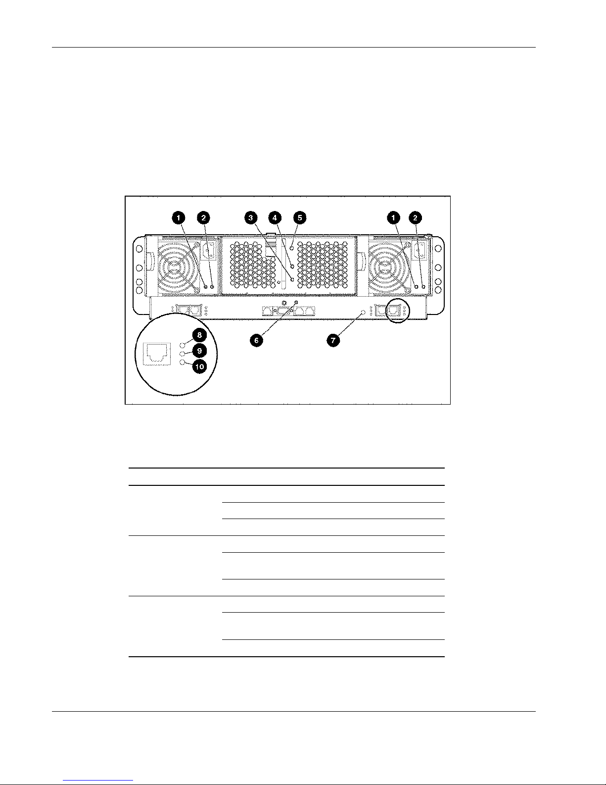
Connectors, Switches, and LEDs
Enclosure Rear Panel LEDs
The enclosure rear panel LEDs differ according to which interconnect tray configuration you
have installed.
Rear panel LEDs with Interconnect Switch Interconnect Tray
Use Figure 4-12 and Table 4-10 to identify the LEDs on the enclosure rear panel with an
interconnect switch interconnect tray.
Figure 4-12: Rear panel LEDs with the interconnect switch
interconnect tray
Table 4-10: Rear Panel LEDs with the Interconnect Switch
Interconnect Tray
Item LED Status Description
1 Power
supply
power
2 Power
supply
fault
3 Enclosure
power
Off No power to the system
Blinking green Standby, AC present
Green System power turned on
Off Power supply OK
Amber No AC power or over-voltage
or over-temperature
Blinking amber Current limit
Off No power to enclosure
Amber Enclosure shutdown; power
available; hibernate
Green Enclosure power on
continued
4-12 HP ProLiant BL e-Class System Maintenance and Service Guide
HP CONFIDENTIAL Codename: Kerr Part Number: 249066-004 Last Saved On: 5/12/03 3:07 PM
Page 64

Connectors, Switches, and LEDs
Table 4-10: Rear Panel LEDs with the Interconnect Switch Interconnect Tray continued
Item LED Status Description
4 Fan health
identification
6 Integrated
Administrator
health
7 Interconnect
switch health
8 Reserved
9 Link\activity
10 Connector
speed
Off Enclosure off, fan health good
Green Enclosure on, fan health good
Amber Fan subsystem degraded
Red Fan subsystem critical
Off Unit not identified 5 Enclosure unit
Blue Identification of unit
Off Enclosure off, Integrated
Administrator health good
Green Enclosure on, Integrated
Administrator health good
Amber Integrated Administrator critical
Green Interconnect switch health good
Yellow Interconnect switch health
degraded
Red Interconnect switch health
critical
Off Switch booting/No power
Green Network link
Flashing green Network activity
Yellow Port disabled
Off No network link
Green 1000 Mbps
Yellow 100 Mbps
Off 10 Mbps
HP ProLiant BL e-Class System Maintenance and Service Guide 4-13
HP CONFIDENTIAL Codename: Kerr Part Number: 249066-004 Last Saved On: 5/12/03 3:07 PM
Page 65
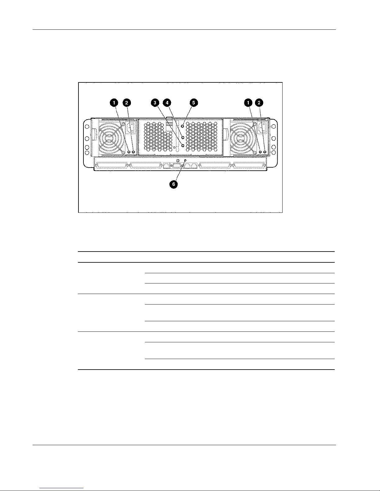
Connectors, Switches, and LEDs
Rear Panel LEDs with RJ-21 Patch Panel Interconnect Tray
Use Figure 4-13 and Table 4-11 to identify the LEDs on the enclosure rear panel with an
RJ-21 patch panel interconnect tray.
Figure 4-13: Rear panel LEDs with the RJ-21 patch panel
interconnect tray
Table 4-11: Rear Panel LEDs with RJ-21 Patch Panel Interconnect Tray
Item LED Status Description
1 Power supply
power
2 Power supply
fault
3 Enclosure
power
Off No power to the system
Blinking green Standby, AC present
Green System power turned on
Off Power supply OK
Amber No AC power or over-voltage or over-
temperature
Blinking amber Current limit
Off No power to enclosure
Amber Enclosure shutdown; power available;
hibernate
Green Enclosure power on
continued
4-14 HP ProLiant BL e-Class System Maintenance and Service Guide
HP CONFIDENTIAL Codename: Kerr Part Number: 249066-004 Last Saved On: 5/12/03 3:07 PM
Page 66

Connectors, Switches, and LEDs
Table 4-11: Rear Panel LEDs with RJ-21 Patch Panel Interconnect Tray continued
Item LED Status Description
4
Fan health
identification
6 Integrated
Administrator
health
Off Enclosure off, fan health unknown
Green Enclosure on, fan health good
Amber Fan subsystem degraded
Red Fan subsystem critical
Off Unit not identified 5 Enclosure unit
Blue Identification of unit
Off Enclosure off, Integrated Administrator
health good
Green Enclosure on, Integrated Administrator
health good
Amber Integrated Administrator critical
HP ProLiant BL e-Class System Maintenance and Service Guide 4-15
HP CONFIDENTIAL Codename: Kerr Part Number: 249066-004 Last Saved On: 5/12/03 3:07 PM
Page 67
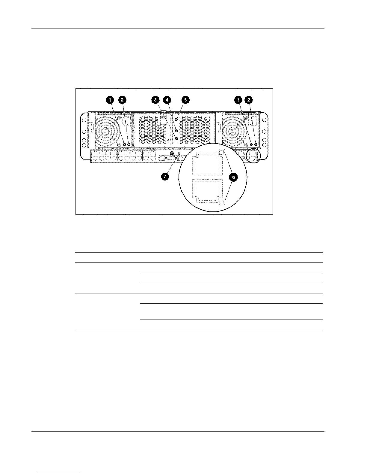
Connectors, Switches, and LEDs
Rear Panel LEDs with RJ-45 Patch Panel Interconnect Tray
Use Figure 4-14 and Table 4-12 to identify the LEDs on the enclosure rear panel with an
RJ-45 patch panel interconnect tray.
Figure 4-14: Rear panel LEDs with RJ-45 patch panel interconnect
tray
Table 4-12: Rear Panel LEDs with RJ-45 Patch Panel Interconnect Tray
Item LED Status Description
1 Power supply
power
2 Power supply
fault
Off No power to the system
Blinking green Standby, AC present
Green System power turned on
Off Power supply OK
Amber No AC power or over-voltage or over-
temperature
Blinking amber Current limit
continued
4-16 HP ProLiant BL e-Class System Maintenance and Service Guide
HP CONFIDENTIAL Codename: Kerr Part Number: 249066-004 Last Saved On: 5/12/03 3:07 PM
Page 68
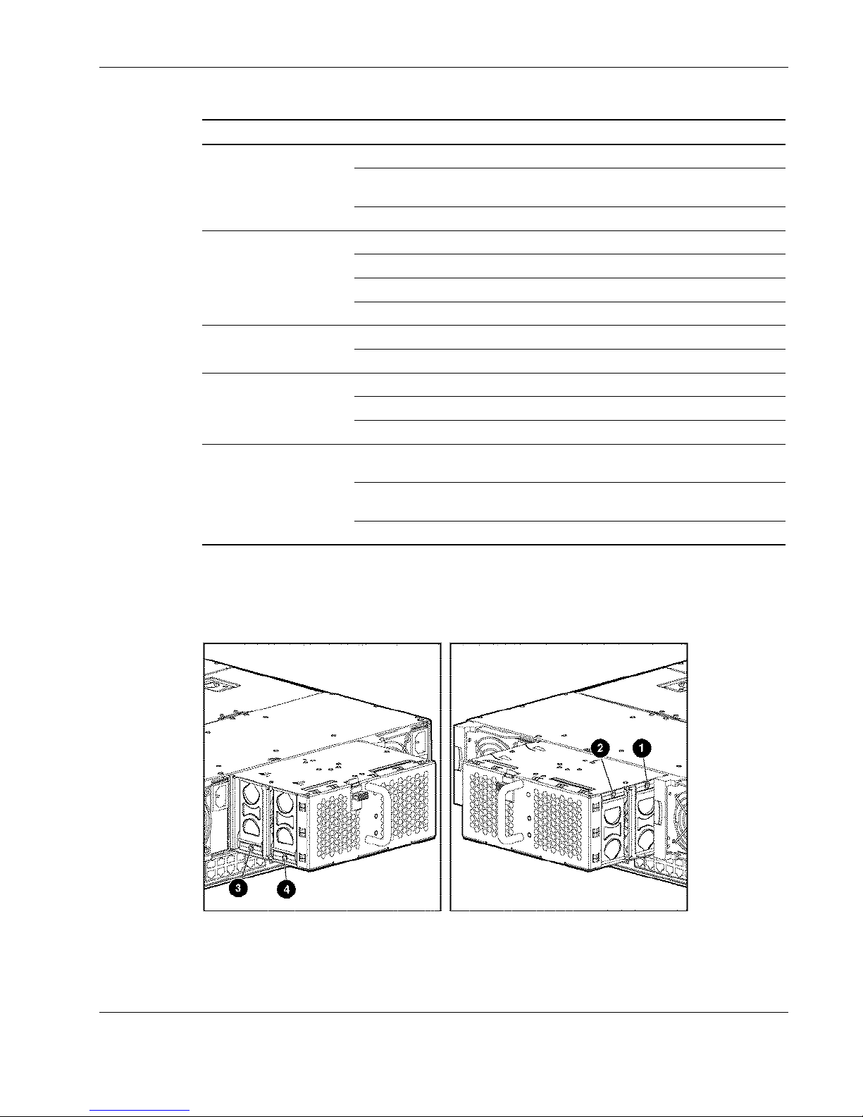
Connectors, Switches, and LEDs
Table 4-12: Rear Panel LEDs with RJ-45 Patch Panel Interconnect Tray continued
Item LED Status Description
3 Enclosure
power
4 Fan health
identification
6 RJ-45
link/activity
7 Integrated
Administrator
health
Off No power to enclosure
Amber Enclosure shutdown; power available;
hibernate
Green Enclosure power on
Off Enclosure off, fan health unknown
Green Enclosure on, fan health good
Amber Fan subsystem degraded
Red Fan subsystem critical
Off Unit not identified 5 Enclosure unit
Blue Identification of unit
On Network link
Off No network link
Flashing Network activity
Off Enclosure off, Integrated Administrator health
unknown
Green Enclosure on, Integrated Administrator health
good
Amber Integrated Administrator critical
Fan Health LEDs
Use Figure 4-15 and Table 4-13 to identify the LEDs on the hot-plug fans.
Figure 4-15: Hot-plug fan health LEDs
HP ProLiant BL e-Class System Maintenance and Service Guide 4-17
HP CONFIDENTIAL Codename: Kerr Part Number: 249066-004 Last Saved On: 5/12/03 3:07 PM
Page 69
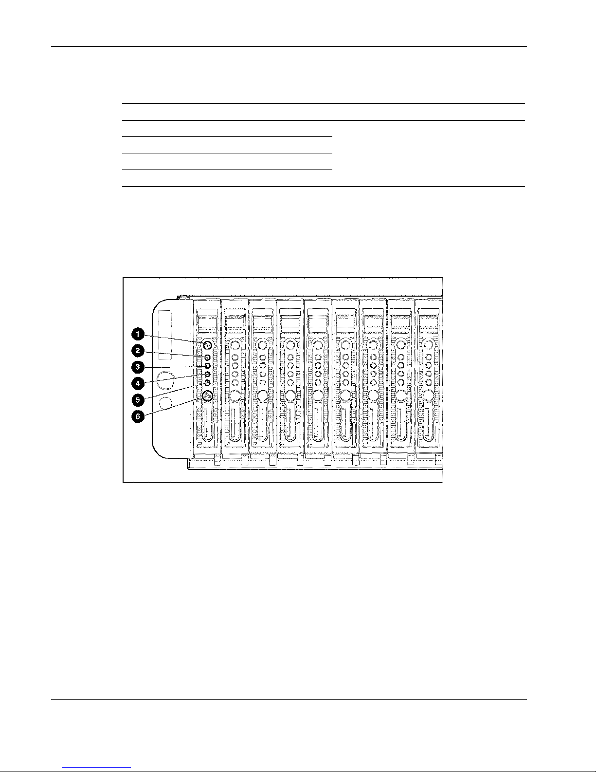
Connectors, Switches, and LEDs
Table 4-13: Hot-Plug Fan Health LEDs
Item LED Function
1 Fan 1
2 Fan 2
3 Fan 3
4 Fan 4
Server Blade and Diagnostic Adapter LEDs
Use Figure 4-16, Figure 4-17 and Table 4-14 to identify the LEDs on the ProLiant BL e-Class
server blades and diagnostic adapter. LEDs on the server blade and the diagnostic adapter are
identical in function and location.
Green = Normal
Amber = Failed
Figure 4-16: Server blade LEDs
4-18 HP ProLiant BL e-Class System Maintenance and Service Guide
HP CONFIDENTIAL Codename: Kerr Part Number: 249066-004 Last Saved On: 5/12/03 3:07 PM
Page 70
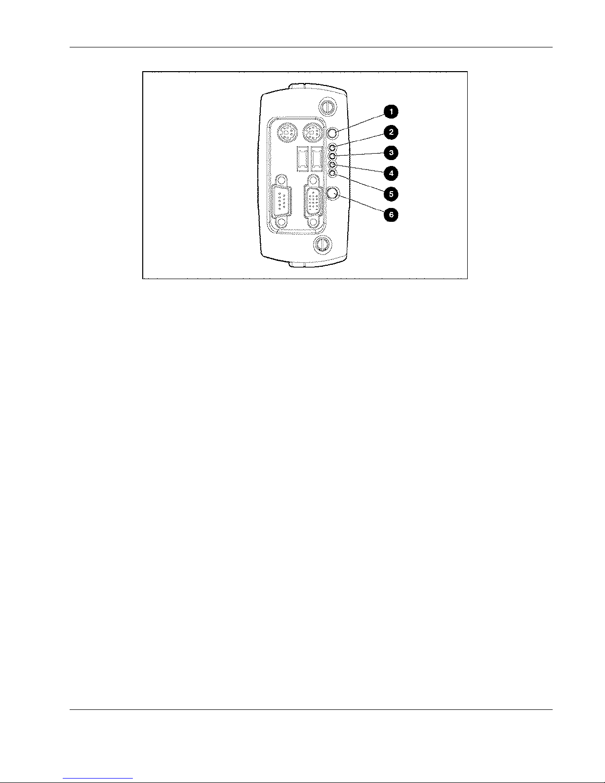
Figure 4-17: Diagnostic adapter LEDs
Connectors, Switches, and LEDs
HP ProLiant BL e-Class System Maintenance and Service Guide 4-19
HP CONFIDENTIAL Codename: Kerr Part Number: 249066-004 Last Saved On: 5/12/03 3:07 PM
Page 71

Connectors, Switches, and LEDs
Table 4-14: Server Blade and Diagnostic Adapter LEDs
Item LED Status Description
Identification
2 Health
3 NIC 1
4 NIC 2
6 Power
Off Unit not identified 1 Unit
Blue Identification of server blade
Off Server blade off and health last good
Green Server blade on and health good
Amber Server blade degraded, or power-up
prohibited by the Integrated Administrator
Red Server blade critical
Off No connection
Green Linked to network
Blinking green Linked and activity on the network
Off No connection
Green Linked to network
Blinking green Linked and activity on the network
Off No drive activity 5 Drive activity
Blinking green Drive activity
Off No AC power to server blade
Amber Enclosure on and health good
Green Server blade power turned on
Blinking green Server blade in standby
4-20 HP ProLiant BL e-Class System Maintenance and Service Guide
HP CONFIDENTIAL Codename: Kerr Part Number: 249066-004 Last Saved On: 5/12/03 3:07 PM
Page 72

Specifications
This chapter provides operating and performance specifications for ProLiant BL e-Class
system components and hardware, including:
ProLiant BL e-Class server blade enclosure •
•
Hot-plug power supply
•
ProLiant BL e-Class C-GbE Interconnect Switch
•
RJ-21 patch panel
•
RJ-45 patch panel
•
ProLiant BL10e and ProLiant BL10e G2 server blade components
— Memory
— ATA hard drive assembly
5
HP ProLiant BL e-Class System Maintenance and Service Guide 5-1
HP CONFIDENTIAL Codename: Kerr Part Number: 249066-004 Last Saved On: 5/12/03 3:10 PM
Page 73

Specifications
ProLiant BL e-Class Server Blade Enclosure
Table 5-1: ProLiant BL e-Class Server Blade Enclosure Specifications
Feature Description
Dimensions
Height 13.1 cm (5.15 in)
Depth 68.6 cm (27 in)
Width 44.5 cm (17.5 in)
Weight with patch panel
No server blades 26.76 kg (59 lb)
20 server blades 42.64 kg (94 lb)
Input requirements
Rated input voltage 100 to 127 VAC 200 to 240 VAC
Rated input frequency 47 to 63 Hz
Rated input current 8.5A at 120 VAC 4.3A @ 240 VAC
Rated input power 1000 W
BTUs per hour 3416
Temperature range1
Operating
Shipping, 72 hours
Relative humidity
(noncondensing)
Operating 10% to 90%
Non-operating 10% to 95%
1
The unit must be capable of functioning in an operating environment of 10° to 35°C. There is an
altitude derating of 1°C per 304.8 m (1.8°F per 1,000 ft) above sea level, up to a maximum of 3,048
m (10,000ft). In a shipping environment (up to 72 hours), the unit shall withstand temperatures of up
to 60°C (140°F) and down to -40°C (-40°F) and altitudes up to 9100 m. In a storage environment (up
to one year), the unit shall withstand temperatures of up to 60°C (140°F) and down to -20°C (-4°F)
and altitudes up to 3,048 m.
2
In an operating mode, the unit must work from 10% to 90% relative humidity (non-condensing)
across the operating temperature range. In a non-operating mode, the chassis must be able to
withstand humidity of 10% to 95% relative humidity (non-condensing) across the temperature range.
2
10° to 35°C (50° to 95°F)
-40° to 60°C (-40° to 140°F)
5-2 HP ProLiant BL e-Class System Maintenance and Service Guide
HP CONFIDENTIAL Codename: Kerr Part Number: 249066-004 Last Saved On: 5/12/03 3:10 PM
Page 74

Hot-Plug Power Supply
Table 5-2: Hot-Plug Power Supply Specifications
Feature Description
Dimensions
Height 9.1 cm (3.6 in)
Depth 25.9 cm (10.2 in)
Width 11.4 cm (4.5 in)
Weight 2.95 kg (6.5 lb)
Input voltage specifications
Rated input voltage 100 to 127 VAC 200 to 240 VAC
Frequency range 47 to 63 Hz
Rated input power 1000 W
Rated input current 8.5 A at 120 VAC 4.3 A @ 240 VAC
Maximum peak power 1167 W
Output voltage specifications
Rated output voltage 5.05 V, 3.33 V, 12.1 V and 5
Rated output power 600 W
Rated output current 5.01 V - 0.5 A ~ 34 A
Maximum peak power 700 W
Specifications
Vaux
3.33 V - 0.5 A ~ 36 A
12.1 V - 0.5 A ~ 38 A
5 Vaux – 0.2 A ~ 8 A
HP ProLiant BL e-Class System Maintenance and Service Guide 5-3
HP CONFIDENTIAL Codename: Kerr Part Number: 249066-004 Last Saved On: 5/12/03 3:10 PM
Page 75

Specifications
C-GbE Interconnect Switch Interconnect Tray
Table 5-3: C-GbE Interconnect Switch Interconnect Tray Specifications
Feature Description
Dimensions
Height 3.3 cm (1.3 in)
Depth 28.7 cm (11.3 in)
Width 42.7 cm (16.8 in)
Capability IEEE 802.3, 802.3u, 802.3ab
Network transfer rate
10 Base-T (half-duplex) 10 Mbps
10 Base-T (full-duplex) 20 Mbps
100 Base-TX (half-duplex) 100 Mbps
100 Base-TX (full-duplex) 200 Mbps
1000 Base-TX (half-duplex) 1000 Mbps
1000 Base-TX (full-duplex) 2000 Mbps
Connector (4) RJ-45 Uplink ports
(1) RJ-45 IA NIC port
(1) DB-9 IA Serial Local port
(2) RJ-45 Reserved
Cable support
10 Base-T Categories 3, 4, or 5 UTP (2 or 4 pair); up to 100 m (328 ft)
100 Base-TX Category 5 UTP (2 or 4 pair); up to 100 m (328 ft)
1000 Base-T Category 5 UTP (4 pair); up to 100 m (328 ft)
Power requirements 4100 mA at 12 V, 5 Vaux at 500 mA, 5 V at 25 mA
Temperature range1
Operating
Non-operating -30° to 60°C (-22° to 140°F)
Relative humidity, noncondensing2
Operating 20% to 80%
Non-operating 5% to 95%
1
Operating temperature has an altitude derating of 1°C per 304.8 (1.8°F per 1,000 ft). The
interconnect tray should not be exposed to direct sunlight. Upper operating limit is 3,048 m (10,000
ft) or 70Kpa/10.1 psia. Upper non-operating limit is 9,144 m (30,000 ft) or 30.3 KPa/4.4 psia.
2
Storage maximum humidity of 95% is based on a maximum temperature of 45°C (113°F). Altitude
minimum for storage is 70 KPa.
10° to 35°C (50° to 95°F)
continued
5-4 HP ProLiant BL e-Class System Maintenance and Service Guide
HP CONFIDENTIAL Codename: Kerr Part Number: 249066-004 Last Saved On: 5/12/03 3:10 PM
Page 76

Specifications
Table 5-3: C-GbE Interconnect Switch Interconnect Tray Specifications continued
Feature Description
Wet bulb temperature
Operating 28°C (82.4°F)
Non-operating 38.7°C (101.7°F)
HP ProLiant BL e-Class System Maintenance and Service Guide 5-5
HP CONFIDENTIAL Codename: Kerr Part Number: 249066-004 Last Saved On: 5/12/03 3:10 PM
Page 77

Specifications
RJ-21 Patch Panel Interconnect Tray
Table 5-4: RJ-21 Patch Panel Interconnect Tray Specifications
Feature Description
Dimensions
Height 3.3 cm (1.3 in)
Depth 28.7 cm (11.3 in)
Width 42.7 cm (16.8 in)
Network transfer rate
10 Base-T (half-duplex) 10 Mbps
10 Base-T (full-duplex) 20 Mbps
100 Base-TX (half-duplex) 100 Mbps
100 Base-TX (full-duplex) 200 Mbps
Connector (4) RJ-21 with 10 NIC ports per connector
(1) RJ-45 IA NIC port
(1) DB-9 IA Serial Local port
(2) RJ-45 Reserved
Cable support
10 Base-TX Categories 3, 4, or 5 UTP (2 or 4 pair); up to 100 m (328 ft)
100 Base-TX Category 5 UTP (2 or 4 pair); up to 100 m (328 ft)
Power requirements 12 V at 525 mA, 5 Vaux at 500 mA, 5V at 20 mA
Temperature range1
Operating
Non-operating -30° to 60°C (-22° to 140°F)
Relative humidity, noncondensing2
Operating 20% to 80%
Non-operating 5% to 95%
Wet bulb temperature
Operating 28°C (82.4°F)
Non-operating 38.7°C (101.7°F)
1
Operating temperature has an altitude derating of 1°C per 304.8 m (1.8°F per 1,000 ft). The
interconnect tray should not be exposed to direct sunlight. Upper operating limit is 3,048 m (10,000
ft) or 70Kpa/10.1 psia. Upper non-operating limit is 9,144 m (30,000 ft) or 30.3 KPa/4.4 psia.
2
Storage maximum humidity of 95% is based on a maximum temperature of 45°C (113°F). Altitude
minimum for storage is 70 KPa.
10° to 35°C (50° to 95°F)
5-6 HP ProLiant BL e-Class System Maintenance and Service Guide
HP CONFIDENTIAL Codename: Kerr Part Number: 249066-004 Last Saved On: 5/12/03 3:10 PM
Page 78

RJ-45 Patch Panel Interconnect Tray
Table 5-5: RJ-45 Patch Panel Interconnect Tray Specifications
Feature Description
Dimensions
Height 3.3 cm (1.3 in)
Depth 28.7 cm (11.3 in)
Width 42.7 cm (16.8 in)
Network transfer rate
10 Base-T (half-duplex) 10 Mbps
10 Base-T (full-duplex) 20 Mbps
100 Base-TX (half-duplex) 100 Mbps
100 Base-TX (full-duplex) 200 Mbps
Connector (40) RJ-45 NIC ports
(1) RJ-45 IA NIC port
(1) DB-9 IA Serial Local port
(2) RJ-45 Reserved
Cable support
10 Base-TX Categories 3, 4, or 5 UTP (2 or 4 pair); up to 100 m (328 ft)
100 Base-TX Category 5 UTP (2 or 4 pair); up to 100 m (328 ft)
Power requirements 12 V at 525 mA, 5 Vaux at 675 mA, 5 V at 25 mA
Temperature range1
Operating
Non-operating -30° to 60°C (-22° to 140°F)
Relative humidity, noncondensing2
Operating 20% to 80%
Non-operating 5% to 95%
Wet bulb temperature
Operating 28°C (82.4°F)
Non-operating 38.7°C (101.7°F)
1
Operating temperature has an altitude derating of 1°C per 304.8 (1.8°F per 1,000 ft). The
interconnect tray should not be exposed to direct sunlight. Upper operating limit is 3,048 m (10,000
ft) or 70Kpa/10.1 psia. Upper non-operating limit is 9,144 m (30,000 ft) or 30.3 KPa/4.4 psia.
2
Storage maximum humidity of 95% is based on a maximum temperature of 45°C (113°F). Altitude
minimum for storage is 70 KPa.
10° to 35°C (50° to 95°F)
Specifications
HP ProLiant BL e-Class System Maintenance and Service Guide 5-7
HP CONFIDENTIAL Codename: Kerr Part Number: 249066-004 Last Saved On: 5/12/03 3:10 PM
Page 79

Specifications
Server Blade Components
Operating and Performance Specifications
Table 5-6: Server Blade Operating and Performance
Specifications
Dimensions
Height 11.94 cm 4.7 in
Depth 39.37 cm 15.5 in
Width 2.03 cm 0.8 in
Weight (maximum) 0.79 kg 1.75 lb
Temperature range1
Operating (See note)
Non-operating (See note):
Shipping
Storage
Relative humidity2
(noncondensing)
Operating (See note) 10% to 90%
Non-operating (See note):
Shipping
Storage
1
Operating temperature has an altitude derating of 1°C per 304.8 m (1.8°F
per 1000 ft). No direct sunlight.
2
Storage maximum humidity of 95% is based on a maximum temperature of
45°C (113°F). Minimum pressure for storage is 70 KPa.
10° to 35°C 50° to 95°F
-40° to 60°C
-20° to 60°C
10% to 90%
10% to 95%
-40° to 140°F
-4° to 140°F
Memory (SDRAM DIMM)
Table 5-7: ProLiant BL10e Server Blade SDRAM DIMM Specifications
Feature Description
Size 128 MB, 256 MB, 512 MB
Speed 133 MHz (operating at 100 MHz)
Width 72 bits
Upgrade requirement Any combination of like-paired SDRAM DIMMs that provide a
Note: Use only 128-MB, 256-MB, or 512-MB, 72-bit wide, 3.3 V, registered ECC SDRAM. SDRAM
can be either 100 or 133 MHz. Use HP SDRAM only.
5-8 HP ProLiant BL e-Class System Maintenance and Service Guide
HP CONFIDENTIAL Codename: Kerr Part Number: 249066-004 Last Saved On: 5/12/03 3:10 PM
minimum of 256 MB
Page 80

Table 5-8: ProLiant BL10e G2 Server Blade DDR SDRAM DIMM Specifications
Feature Description
Size 128 MB, 256 MB, 512 MB
Speed 133 MHz (operating at 100 MHz)
Width 72 bits
Upgrade requirement Any combination of like-paired DDR SDRAM DIMMs that provide
Note: Use only 128-MB, 256-MB, or 512-MB, 72-bit wide, 3.3 V, registered ECC DDR SDRAM.
SDRAM can be either 100 or 133 MHz. Use HP DDR SDRAM only.
ATA Hard Drive Assembly
Table 5-9: ATA Hard Drive Assembly Specifications
Specifications
a minimum of 256 MB
Feature 30-GB Hard Drive 40-GB/4200 RPM
Hard Drive
Capacity 30,005 MB 40,007 MB 40,007 MB
Height 9.5 mm (0.374 in) 9.5 mm (0.374 in) 9.5 mm (0.374 in)
Size 70mm (2.76 in) width
9.5mm (.37 in) height
100mm (3.94 in)
diameter
Interface ATA-5 (IDE) 100 MB/s ATA-5 (IDE) 100 MB/s ATA-5 (IDE) 100
Transfer rate 16.3 - 30.2 MB/sec
(Disk-Buffer)
Rotational speed 4,200 RPM 4,200 RPM 5,400 RPM
Bytes per sector 512 512 512
Logical blocks 58,605,120 (LBA) 78,140,160 (LBA) 78,140,160 (LBA)
Operating
temperature
10°C to 35°C (50°F to
95°F) (Ambient)
70mm (2.76 in) width
9.5mm (.37 in) height
100mm (3.94 in)
diameter
18.7 to 34.7 MB/sec
(Disk-Buffer)
10°C to 35°C (50°F to
95°F) (Ambient)
40-GB/5400 RPM
Hard Drive
70mm (2.76 in) width
9.5mm (.37 in) height
100mm (3.94 in)
diameter
MB/s
27.8 to 44.1 MB/sec
(Disk-Buffer)
10°C to 35°C (50°F to
95°F) (Ambient))
HP ProLiant BL e-Class System Maintenance and Service Guide 5-9
HP CONFIDENTIAL Codename: Kerr Part Number: 249066-004 Last Saved On: 5/12/03 3:10 PM
Page 81

A
access door, opening 2-16
Automatic Server Recovery-2 (ASR-2)
access 3-2
description 3-2
B
button
enclosure unit identification 4-9
buttons
blade unit identification 4-8
enclosure unit identification 4-8
power 4-8, 4-9
reset, Integrated Administrator 4-9
C
cables and cabling 5-5, 5-8, 5-9
center wall assembly
removing 2-28
replacing 2-29
spare part number 1-5
component-level repairs vii
components
center wall assembly 1-5
diagnostic adapter 1-5
DIMM 1-5, 1-6
enclosure 1-2
enclosure status assembly 1-5
fan 1-5
fan backplane assembly 1-5
fan cage 1-5
hard drive 1-5
Integrated Administrator module 1-5
interconnect tray 1-6
power supply 1-5
rack-mounting hardware kit 1-6
server blade 1-3, 1-4, 1-5
server blade battery 1-5
server blade blank 1-5
Index
connectors
diagnostic adapter 4-7
enclosure status cable 4-5
fan cable 4-5
RJ-21 patch panel 4-3
RJ-45 patch panel 4-4
server blade 4-6
current
rated input 5-2, 5-4
rated output 5-4
D
diagnostic adapter
connectors 4-7
installing 3-4
LEDs 4-19
spare part number 1-5
diagnostic tools
diagnostic adapter 3-4
software 3-2, 3-3, 3-4
Diagnostics utility
access 3-3
description 3-3
DIMM socket keys, locations 2-25, 2-26
DIMMs
removing 2-24
replacing 2-25
spare part number 1-5, 1-6
disconnecting power cords 2-4
E
electric shock
warning 2-2
electric shock icon 2-2
electrostatic discharge 2-1
enclosure
components 1-2
graceful shutdown 2-10
LEDs 4-12, 4-14, 4-17
power button 4-9
powering up 2-11
removing 2-15
HP ProLiant BL e-Class System Maintenance and Service Guide Index-1
HP CONFIDENTIAL Codename: Kerr Part Number: 249066-004 Last Saved On: 5/12/03 3:16 PM
Page 82

Index
replacing 2-16 hot surfaces, warnings 2-3
specifications 5-2
hot-plug power supply
unit identification button 4-8 removing 2-5
unit identification button 4-9
replacing 2-5
enclosure power LED 4-12, 4-14, 4-17 HP
enclosure rear panel LEDs 4-12 authorized reseller ix
enclosure status assembly telephone numbers ix
removing 2-22 website ix
replacing 2-24 humidity, server 5-10
spare part number 1-5 humidity, server blade enclosure 5-2
enclosure status cable connectors 4-5
exclamation point icon 2-2
I
F
icons on equipment 2-2
IML See Integrated Management Log (IML)
fan input requirements 5-2
LEDs 4-15, 4-17 Insight Manager 7
access 3-3 removing 2-6
replacing 2-7 description 3-3
spare part number 1-5 Integrated Administrator
LED 4-13, 4-15, 4-17 fan backplane assembly
removing 2-20 reset button 4-9
replacing 2-21 Integrated Administrator module
spare part number 1-5 spare part number 1-5
fan cable connector 4-5 Integrated Administrator module
fan cage removing 2-21
replacing 2-22 removing 2-18
replacing 2-20 Integrated Management Log (IML)
spare part number 1-5 access 3-3
description 3-3 fan LEDs 4-17
fault LED 4-12, 4-14, 4-16 viewing 3-3
frequency, rated input 5-2 interconnect switch
connectors 4-2 front panel switches 4-8
LEDs 4-12
G
grounding viii
guidelines 2-1
plug viii
guides
HP Servers Troubleshooting Guide 3-3
HP Service Quick Reference Guide ix
network transfer rates 5-5
specifications 5-5
supported cable types 5-5
interconnect tray
removing 2-14
replacing 2-14, 2-30
spare part number 1-6
swapping 2-29
H
hard drive activity LED 4-20
hard drive assembly
removing 2-27
replacing 2-27
hard drive battery, spare part number 1-5
hazard symbol 2-2
hazardous energy circuits symbol 2-2
help resources ix
hot surfaces
warning 2-2
Index-2 HP ProLiant BL e-Class System Maintenance and Service Guide
HP CONFIDENTIAL Codename: Kerr Part Number: 249066-004 Last Saved On: 5/12/03 3:16 PM
L
labels, symbols on equipment 2-2
LEDs
diagnostic adapter 4-19
enclosure front panel 4-11
enclosure health 4-11
enclosure power 4-12, 4-14, 4-17
enclosure rear panel 4-12
enclosure unit identification 4-11, 4-13, 4-15,
4-17
fan 4-17
Page 83

Index
fan health 4-13, 4-15, 4-17
fault 4-12, 4-14, 4-16
hard drive activity 4-20
Integrated Administrator health 4-13, 4-15,
4-17
interconnect switch 4-12
NIC 1 4-20
NIC 2 4-20
power 4-14, 4-16, 4-20
RJ-21 patch panel 4-14
RJ-45 activity 4-17
RJ-45 patch panel 4-16
server blade 4-18
server blade health 4-20
unit identification 4-20
M
maintenance switches 4-10
multiple sources of power
warning 2-2
N
network transfer rates 5-5, 5-8, 5-9
NIC LEDs 4-20
null-modem cable pin-out 3-6
O
opening the access door 2-16
P
patch panels, RJ-21
connectors 4-3
network transfer rates 5-8
specifications 5-8
supported cable types 5-8
patch panels, RJ-45
connectors 4-4
network transfer rates 5-9
specifications 5-9
supported cable types 5-9
power button 4-8, 4-9
power cords, warning 2-4
power LEDs 4-14, 4-16, 4-20
power supply
spare part number 1-5
specifications 5-4
R
rack
stabilization 2-3
warnings and cautions 2-3
weight 2-3
rack stability
warning 2-3, 2-4
rack weight
warning 2-3
rack-mounting hardware kit spare part number 1-6
rated input
current 5-2
frequency 5-2
power 5-2
voltage 5-2
RBSU See ROM-Based Setup Utility
removing
center wall assembly 2-28
DIMM 2-24
DIMMs 2-24
enclosure 2-15
enclosure status assembly 2-22
fan 2-6
fan backplane assembly 2-20
fan cage 2-18
hard drive assembly 2-27
hot-plug power supply 2-5
Integrated Administrator module 2-21
interconnect tray 2-14
server blade 2-12
server blade battery 2-27
server blade blank 2-13
replacing
center wall assembly 2-29
DIMM 2-25
enclosure 2-16
enclosure status assembly 2-24
fan 2-7
fan backplane assembly 2-21
fan cage 2-20
hard drive assembly 2-27
hot-plug power supply 2-5
Integrated Administrator module 2-22
interconnect tray 2-14, 2-30
server blade 2-12
server blade battery 2-28
server blade blank 2-14
reset button 4-9
RJ-21 patch panel
connectors 4-3
LEDs 4-14
HP ProLiant BL e-Class System Maintenance and Service Guide Index-3
HP CONFIDENTIAL Codename: Kerr Part Number: 249066-004 Last Saved On: 5/12/03 3:16 PM
Page 84

Index
RJ-45 activity LED 4-17
RJ-45 patch panel
connectors 4-4
LEDs 4-16
RJ-45 receptacle symbol 2-2
ROM-Based Setup Utility (RBSU)
access 3-4
description 3-4
ROMPaq Utility
access 3-4
description 3-4
interconnect switch 5-5
operating and performance 5-10
patch panels, RJ-21 5-8
patch panels, RJ-45 5-9
power supply 5-4
server blades 5-10
swapping the interconnect tray 2-29
switches
front panel 4-8
rear panel 4-9
symbols on equipment 2-2
S T
screwdriver icon 2-2 technician notes vii
server blade telephone numbers ix
components 1-3, 1-4 telephone symbol 2-2
connectors 4-6 temperature
emergency shutdown 2-9, 2-11 ATA hard drive assembly 5-11
graceful shutdown 2-8 interconnect switch interconnect tray 5-5
LEDs 4-18 RJ-21 patch panel interconnect tray 5-8
power button 4-8 RJ-45 patch panel interconnect tray 5-9
powering up 2-9 server blade enclosure 5-2
removing 2-12 server blades 5-10
replacing 2-12
spare part number 1-5
unit identification button 4-8
warnings and cautions 2-3
server blade battery
removing 2-27
replacing 2-28
spare part number 1-5
server blade bay
U
unit identification LED 4-20
utilities
Diagnostics 3-3
Insight Manager 7 3-3
RBSU 3-4
ROMPaq 3-4
caution 2-13
server blade blank
removing 2-13
replacing 2-14
spare part number 1-5
server blade maintenance switch (SW1)
default settings 4-10
locations and functions 4-10
server blades
specifications 5-10
size, server 5-10
specifications
DIMM 5-10
V
ventilation clearances viii
voltage
rated input 5-2, 5-4
rated output 5-4
W
warranty viii
weight
rack 2-3
warnings 2-3
enclosure 5-2
hard drive 5-11
Index-4 HP ProLiant BL e-Class System Maintenance and Service Guide
HP CONFIDENTIAL Codename: Kerr Part Number: 249066-004 Last Saved On: 5/12/03 3:16 PM
 Loading...