

Page 1
HP ProLiant BL685c G6 Server
J
Blade
Installation Instructions
Overview
The following steps are necessary to install a server blade:
Install and configure an HP BladeSystem c-Class enclosure.
1.
2. Install interconnect modules in the enclosure.
3. Connect the interconnect modules to the network.
4. Install any server blade options.
5. Install a server blade.
Assemble and install full-height device bay blanks, as needed.
6.
7. Complete the server blade configuration.
For definitions of the acronyms used in this document, refe
"Acronyms and abbreviations" in the server blade user guide.
r to
Installing an HP BladeSystem cClass enclosure
Before performing any server blad
e-specific procedures, install an
HP BladeSystem c-Class enclosure.
The most current documentation for server blades and other
HP BladeSystem components is available at the HP website
(http://www.hp.com/go/bladesystem/documentation
Documentation is also availabl
e in the following locations:
).
• Documentation CD that ships with the enclosure
HP Business Support Center website
•
(http://www.hp.com/support
• HP Technical Documentation
)
website (http://docs.hp.com
)
Preparing the enclosure
HP BladeSystem enclosures ship with device bay dividers to support
half-height devices. To install a fu
and the corresponding device bay divider.
CAUTION:
To prevent improper cooling and thermal
damage, do not operate the se
unless all hard drive and device bays are populated with
either a component or a blank.
1. Remove the device bay blank.
ll-height device, remove the blanks
rver blade or the enclosure
© Copyright 2009 Hewlett-Packard Development Company, L.P.
The information contained herein is subject to chan
only warranties for HP products and services are set fo
warranty statements accompanying su
herein should be construed as constituting an additional warranty. H
not be liable for technical or editorial errors or omissions co
Part Number 508506-001
anuary 2009 (First Edition)
ch products and services. Nothing
ge without notice. The
rth in the express
ntained herein.
P shall
Page 2
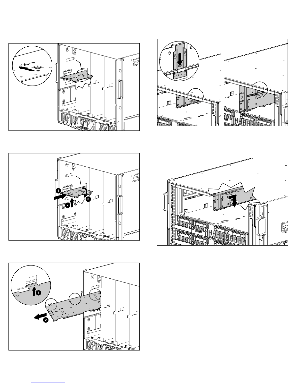
Remove the three adjacent blanks.
2.
Removing a c7000 device bay divider
1. Slide the device bay shelf locking tab to the left to open it.
Removing a c3000 device bay mini-divider or
device bay divider
1. Slide the locking tab down.
Push the device bay shelf back unti
2.
l it stops, lift the right side
slightly to disengage the two tabs from the divider wall, and
then rotate the right edge
Lift the left side of the device bay shelf to disengage the three
3.
downward (clockwise).
tabs from the divider wall, and then remove it from the
enclosure.
Remove the mini-divider or divider:
2.
c3000 mini-divider:
o
Push the divider toward the ba
ck of the enclosure until the
divider drops out of the chassis.
o c3000 divider:
Push the divider toward the back of the enclosure until it
a.
stops.
b. Slide the divider to the left to disengage the tabs from the
wall.
c. Rotate the divider clockwise.
Page 3
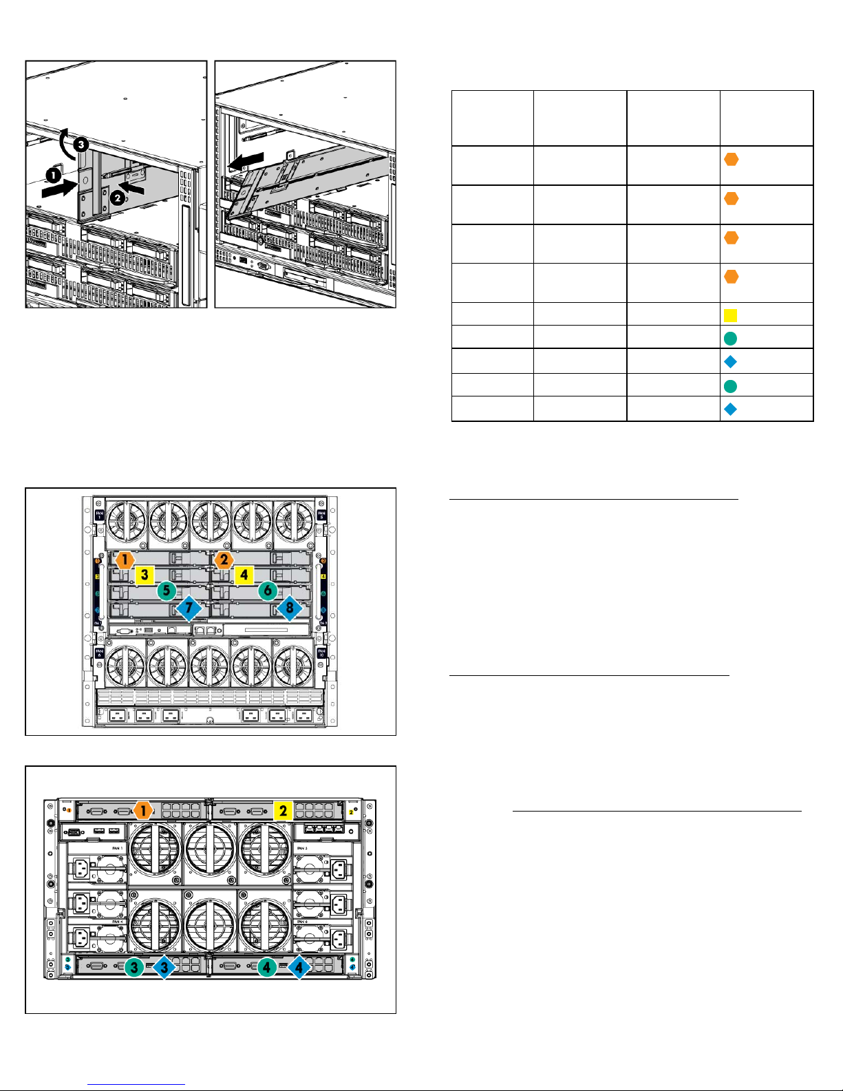
d. Remove the divider from the enclosure.
Installing interconnect modules
For specific steps to install interconnect modules, see the
documentation that ships with the interconnect module.
Interconnect bay numbering and device
mapping
• HP BladeSystem c7000 Enclosure
To support network connections for specific signals, install an
interconnect module in the bay corresponding to the embedded NIC
or mezzanine signals.
Server blade
signal
NIC 1
c7000
interconnect
bay
c3000
interconnect
bay
1 1
Interconnect
bay labels
(Embedded)
NIC 2
2 1
(Embedded)
NIC 3
1 1
(Embedded)
NIC 4
2 1
(Embedded)
Mezzanine 1 3 and 4 2
Mezzanine 2 5 and 6 3 and 4
7 and 8 3 and 4
Mezzanine 3 5 and 6 3 and 4
For detailed port mapping inform
enclosure installation poster or
7 and 8 3 and 4
ation, see the HP BladeSystem
the HP BladeSystem enclosure setup
and installation guide on the HP website
(http://www.hp.com/go/bladesystem/documentation
).
HP BladeSystem c3000 Enclosure
•
Connecting to the network
To connect the HP BladeSystem to
be configured with network interconnect devices to manage signals
between the server blades and the external network.
Two types of interconnect modules
c-Class enclosures: Pass-thru module
information about interconnect module options, see the HP w
(http://www.hp.com/go/bladesystem/interconnects
a network, each enclosure must
are available for HP BladeSystem
s and switch modules. For more
ebsite
).
Installing server blade options
Before installing and initializing the server blade, install any server
blade options, such as an addition
mezzanine card. For server blade op
see the HP ProLiant BL685c G6 Server Blade User Guide
HP website (http://www.hp.com/g
al processor, hard drive, or
tions installation information,
on the
o/bladesystem/documentation
).
Page 4
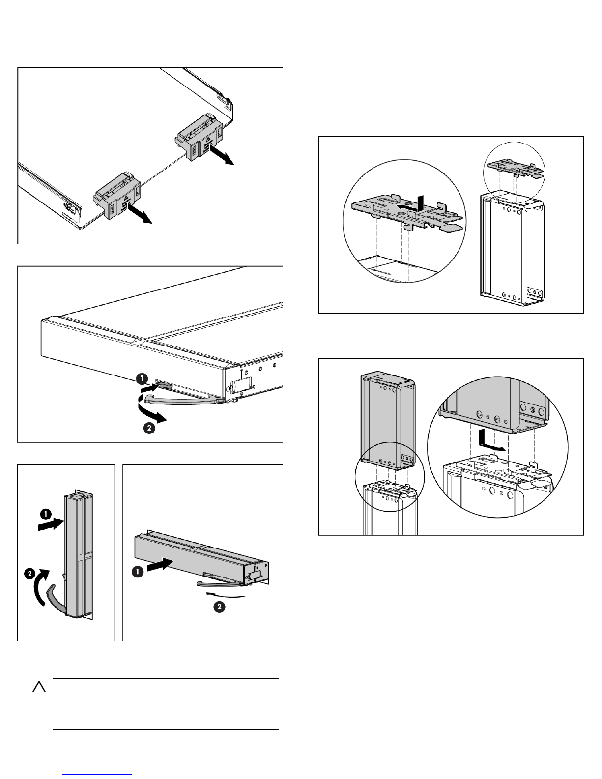
Installing a server blade
1. Remove the connector covers.
Prepare the server blade for installation.
2.
1. Obtain the coupler plate:
o If you are using a device ba
enclosure, the coupler plate ca
y blank that came with the
n be found with the contents
of the full-height device shipping box.
If you are using a device bay
o
an option, remove the coupler
2. Fit the coupler plate in to the
blank that you purchased as
plate from inside the blank.
slots on top of the blank, and
slide the coupler plate back until it snaps into place.
Fit the slots on the bottom of the second blank on to the tabs on
3.
the coupler plate, and slide the second blank forward until it
snaps in place.
Install the server blade.
3.
Assembling a full height blank
CAUTION:
damage, do not operate the se
To prevent improper cooling and thermal
rver blade or the enclosure
unless all hard drive and device bays are populated with
either a component or a blank.
Install the full-height blank into the device bay.
4.
Completing the configuration
To complete the server blade and
the overview card that ships with the enclosure.
HP BladeSystem configuration, see
 Loading...