

Page 1
Product End-of-Life Disassembly Instructions
Product Category:
Personal Computers
Marketing Name / Model
1.0 Items Requiring Selective Treatment
Quantity
Printed Circuit Boards (PCB) or Printed Circuit
With a surface greater than 10 sq
cm 2
Batteries
All types including standard alkaline and lithium coin
1 Mercury
-
containing components
For example, mercury in lamps, display backlights,
Liquid Crystal Displays (LCD) with a surface greater
Includes background
illuminated displays with gas
Cathode Ray Tubes (CRT)
Capacito
rs / condensers (Containing PCB
/PCT)
Electrolytic Capacitors / Condensers measuring
5 External electrical cables and cords
Power cord
1
Gas Discharge Lamps
Plastics containing Brominated Flame Retardants
Components and parts containing toner and ink,
Include the cartridges, print heads, tubes, vent
Components and waste containing asbestos
[List multiple models if applicable.]
HP ProDesk 485 G1 Microtower Business PC
Purpose: The document is intended for use by end-of-life recyclers or treatment facilities. It provides the basic instructions
for the disassembly of HP products to remove components and materials requiring selective treatment, as defined by EU
directive 2002/96/EC, Waste Electrical and Electronic Equipment (WEEE).
1.1 Items listed below are classified as requiring selective treatment.
1.2 Enter the quantity of items contained within the product which require selective treatment in the right column, as
applicable.
Item Description Notes
Assemblies (PCA)
or button style batteries
scanner lamps, switches, batteries
than 100 sq cm
greater than 2.5 cm in diameter or height
weighing > 25 grams (not including PCBs or PCAs
already listed as a separate item above)
including liquids, semi-liquids (gel/paste) and toner
discharge lamps
chambers, and service stations.
of items
included
in product
EL-MF877-00 Page 1
Template Revision B
PSG instructions for this template are available at EL-MF877-01
Page 2
Components, parts and materials containing
refractory ceramic fibers
Components, parts and materials containing
radioactive substances
2.0 Tools Required
Tool Description
Tool Size (if
Screw driver
T-15 M
icro shear
YN-3
Screw driver
PH1
Description #4
Description #5
3.0 Product Disassembly Process
List the type and size of the tools that would typically be used to disassemble the product to a point where components
and materials requiring selective treatment can be removed.
applicable)
3.1 List the basic steps that should typically be followed to remove components and materials requiring selective treatment:
1. Remove access panel. (see Figure 1-3)
2. Remove front bezel. (see Figure 4)
3. Disconnect cooler cable then remove the cooler from board. (see Figure5-7)
4. Disconnect 24 pin power cable、SATA cable、SATA power cable、CPU power cable. (see Figure 8-11)
5. Remove the ODD and HDD from chassis (see Figure 12-16)
6. Disconnect the MCR cable from board then remove the MCR. (see Figure 17-19)
7. Disconnect system fan cable then remove the system fan from chassis (see Figure 20-22)
8. Disconnect FIO cables and open the cable clip. (see Figure 23-24)
9. Remove the FIO module from chassis. (see Figure 25-26)
10. Disconnect PWR cable then remove it from chassis. (see Figure 27-28)
11. Disconnect speaker cable then remove it from chassis. (see Figure 29-31)
12. Remove the Memory from chassis. (see Figure 32)
13. Remove the battery from the board. (see Figure 33)
14. Remove Mother board from chassis. (see Figure 34-36)
15. Remove the I/O shielding from chassis. (see Figure 37)
16. Remove the PSU from chassis. (see Figure 38&39)
17. Remove the PSU chassis and remove the PSU board.. (see Figure 40-43)
18. Remove the Electrolytic Capacitors from PSU board. (see Figure 44-50)
3.2 Optional Graphic. If the disassembly process is complex, insert a graphic illustration below to identify the items
contained in the product that require selective treatment (with descriptions and arrows identifying locations).
EL-MF877-00 Page 2
Template Revision B
PSG instructions for this template are available at EL-MF877-01
Page 3
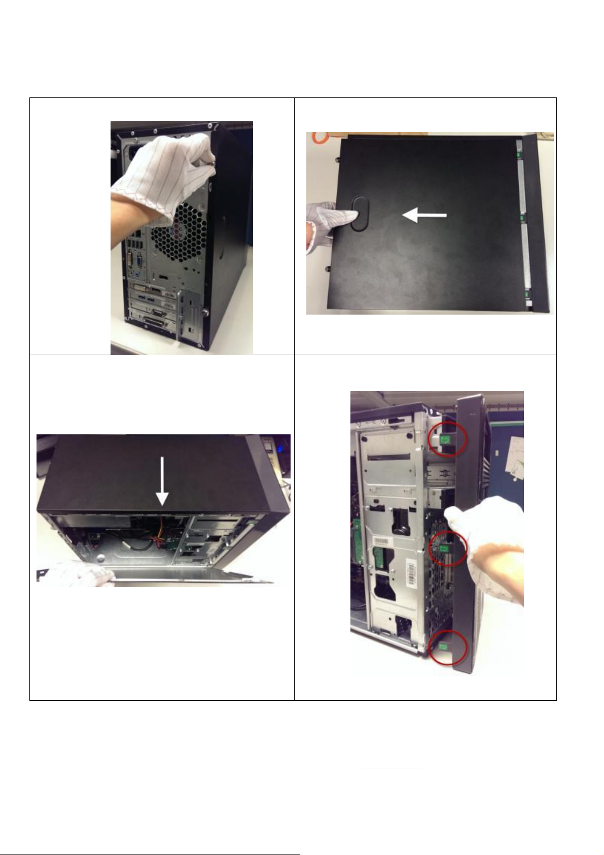
Figure1 Loose
the two screws
from access panel
Figure2
Slide the access panel back
Figure3 R
otate the top of the panel
away
to remove it
Figure4 Pull the 3 hooks and r
otate
to remove the front
bezel
EL-MF877-00 Page 3
Template Revision B
PSG instructions for this template are available at EL-MF877-01
Page 4
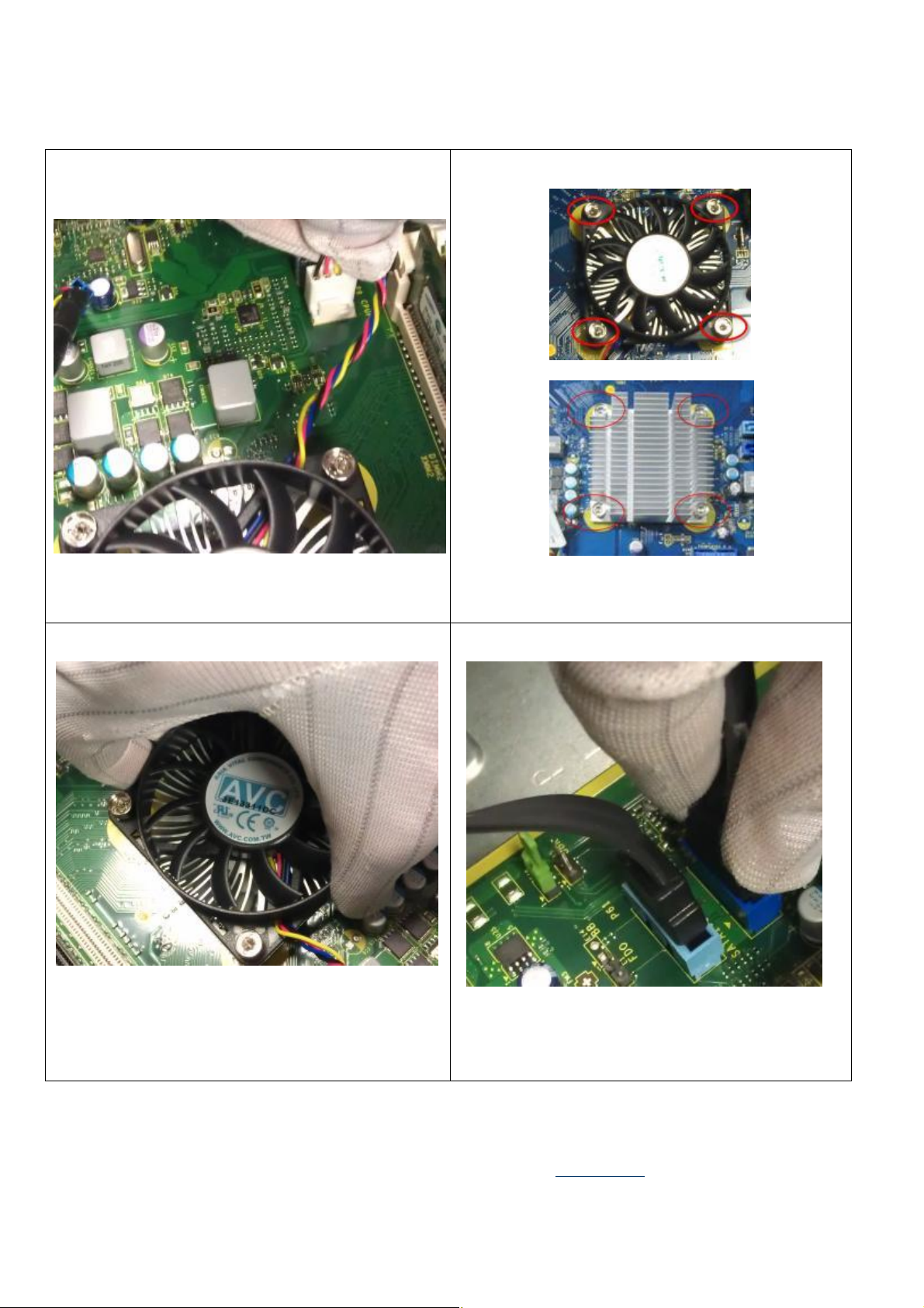
Figure5 Disconnect the cooler cable from MB
Figure6 Loose 4 screws from cooler and remove it
Figure7 Remove the cooler from board
Figure8 Disconnect the SATA cables form board
EL-MF877-00 Page 4
Template Revision B
PSG instructions for this template are available at EL-MF877-01
Page 5
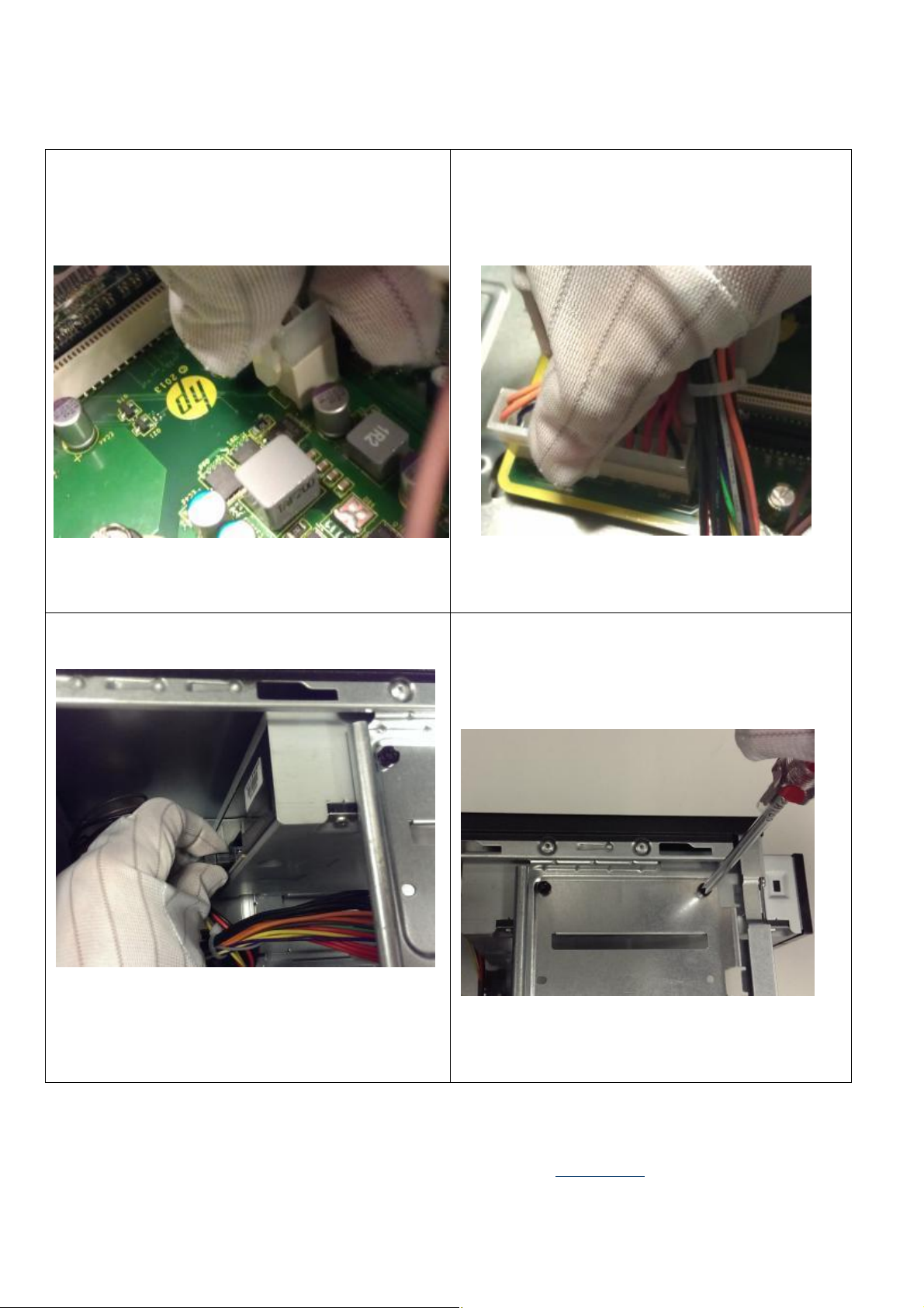
Figure1
1 Disconnect
the SATA and power cables from
Figure9 Disconnect the CPU power cable from board
ODD
Figure10 Disconnect the 24pin power cable from MB
Figure12 Loose the ODD screws
EL-MF877-00 Page 5
Template Revision B
PSG instructions for this template are available at EL-MF877-01
Page 6
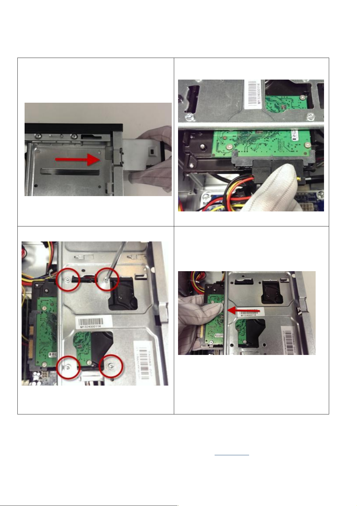
Figure14
Disconnect
the SATA and power cables from
Figure13 Remove the ODD from chassis
HDD
Figure15 Loose the HDD screws
Figure16 Remove the HDD form chassis
EL-MF877-00 Page 6
Template Revision B
PSG instructions for this template are available at EL-MF877-01
Page 7
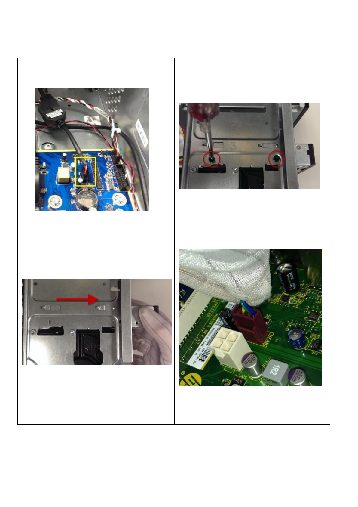
Figure17 Disconnect the MCR cable from MB
Figure19 Remove the MCR from chassis
Figure18 Loose the MCR screws
Figure20 Disconnect system fan cable from board
EL-MF877-00 Page 7
Template Revision B
PSG instructions for this template are available at EL-MF877-01
Page 8
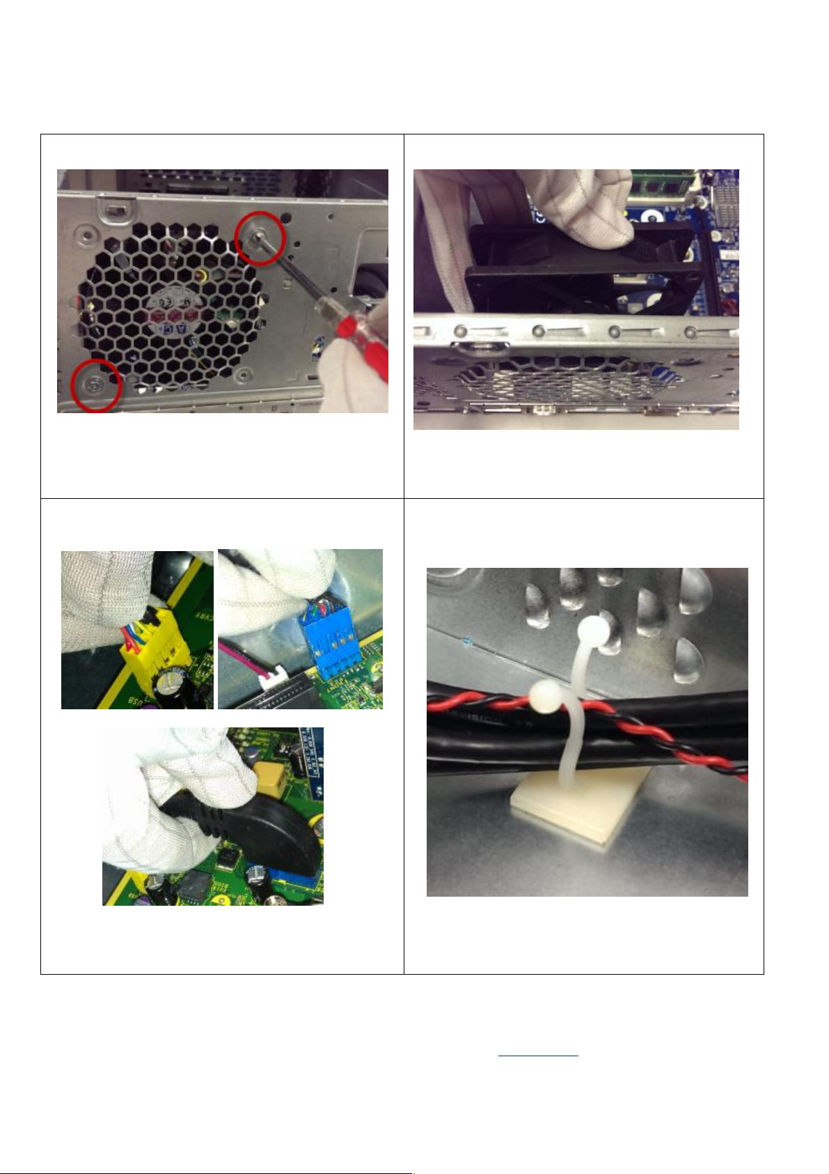
Figure23
Disconnect
FIO cable
include
USB 3.0 , USB
Figure21 Loose 2 screws from system fan
2.0 , Audio
Figure22 Remove the system fan from chassis
Figure24 Open the cable clip
EL-MF877-00 Page 8
Template Revision B
PSG instructions for this template are available at EL-MF877-01
Page 9
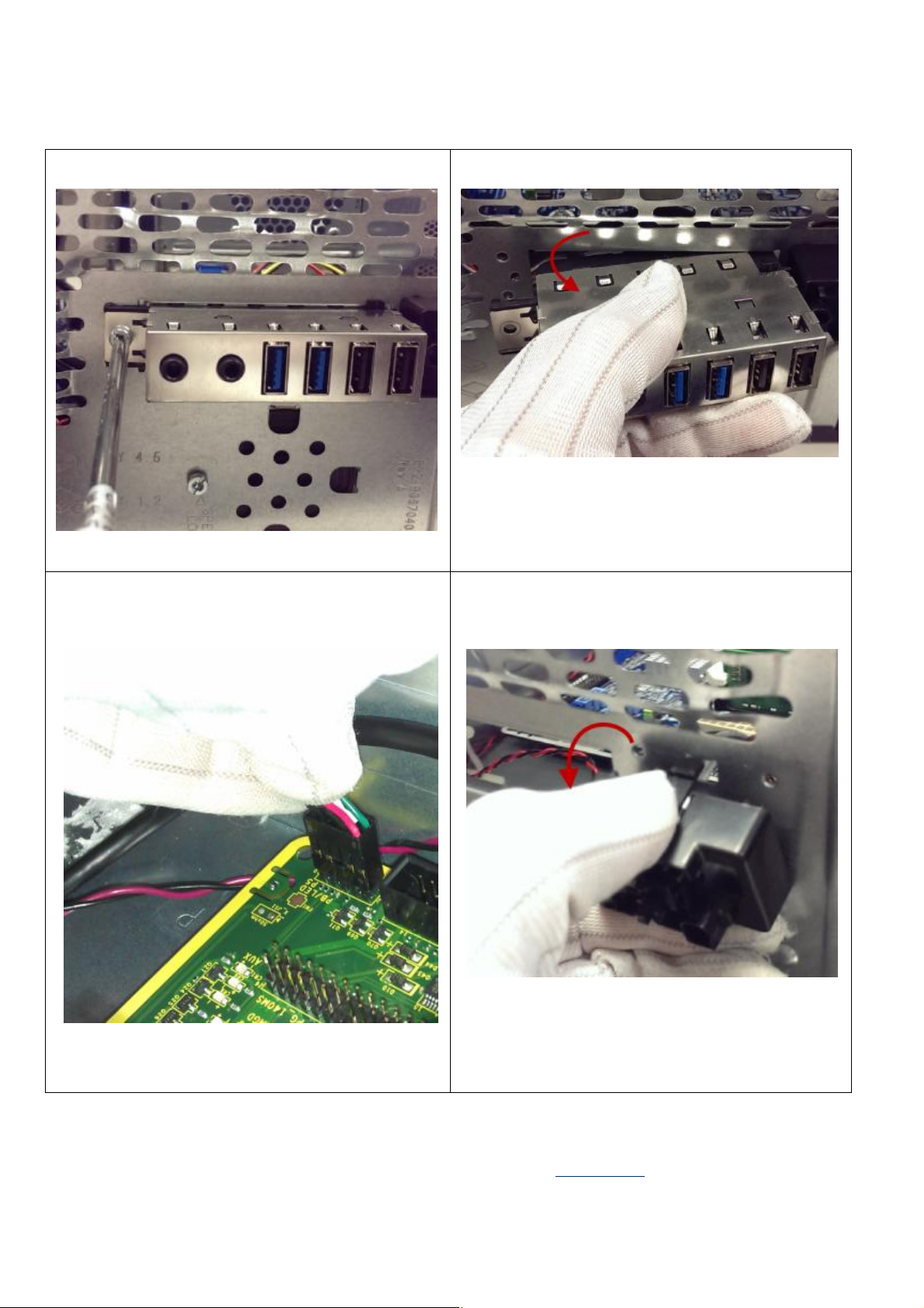
Figure25 Loose the screw of the FIO cable
Figure27 Disconnect PWR cable from MB
Figure26 Remove the FIO cable from chassis
Figure28 Remove the PWR cable
EL-MF877-00 Page 9
Template Revision B
PSG instructions for this template are available at EL-MF877-01
Page 10
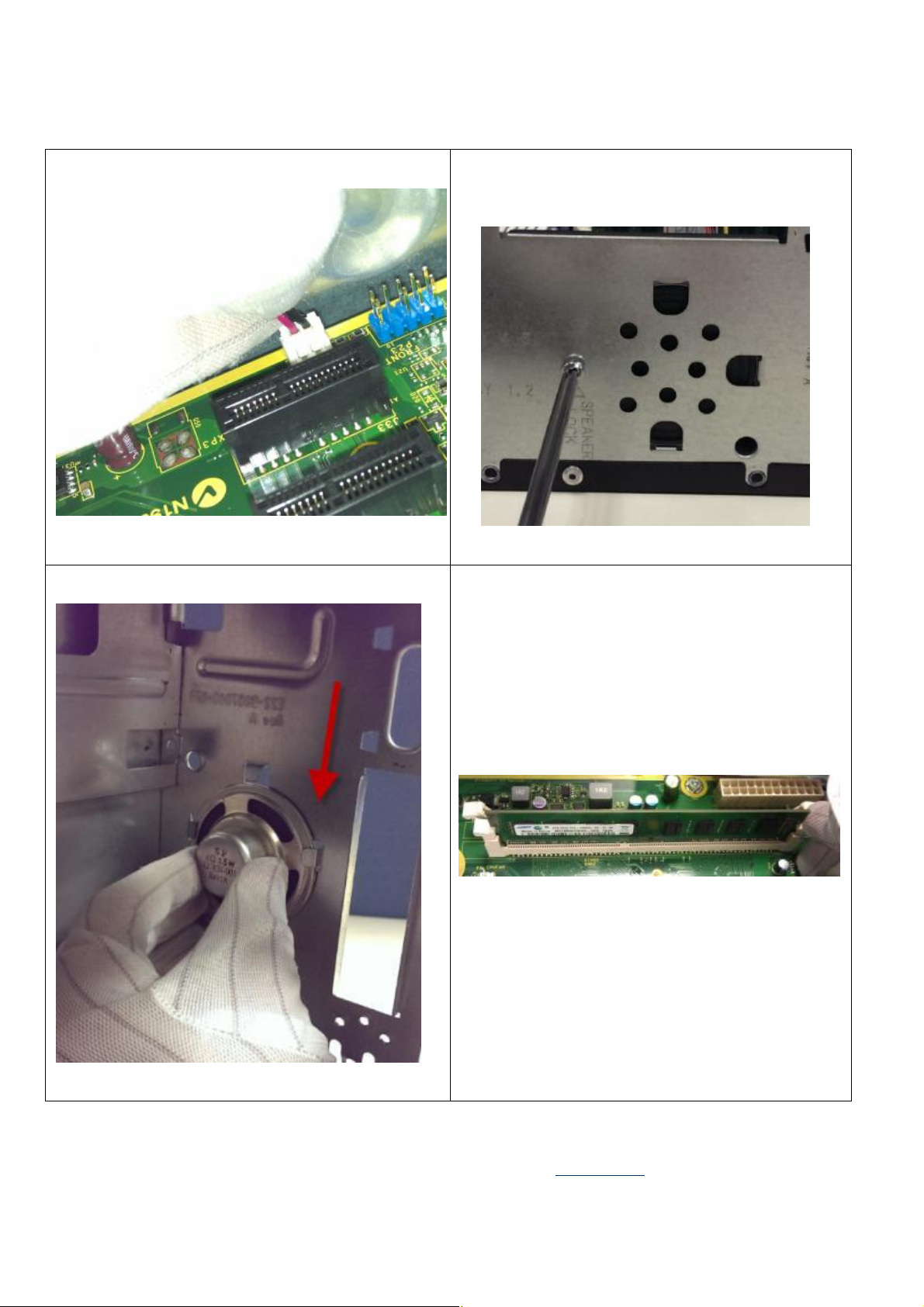
Figure
32 Push
the hooks
on both sides
and then
pick up
Figure29 Disconnect speaker cable from board
Figure31 Remove the speaker form chassis
Figure30 Loose the screw of speaker
the memory
EL-MF877-00 Page 10
Template Revision B
PSG instructions for this template are available at EL-MF877-01
Page 11
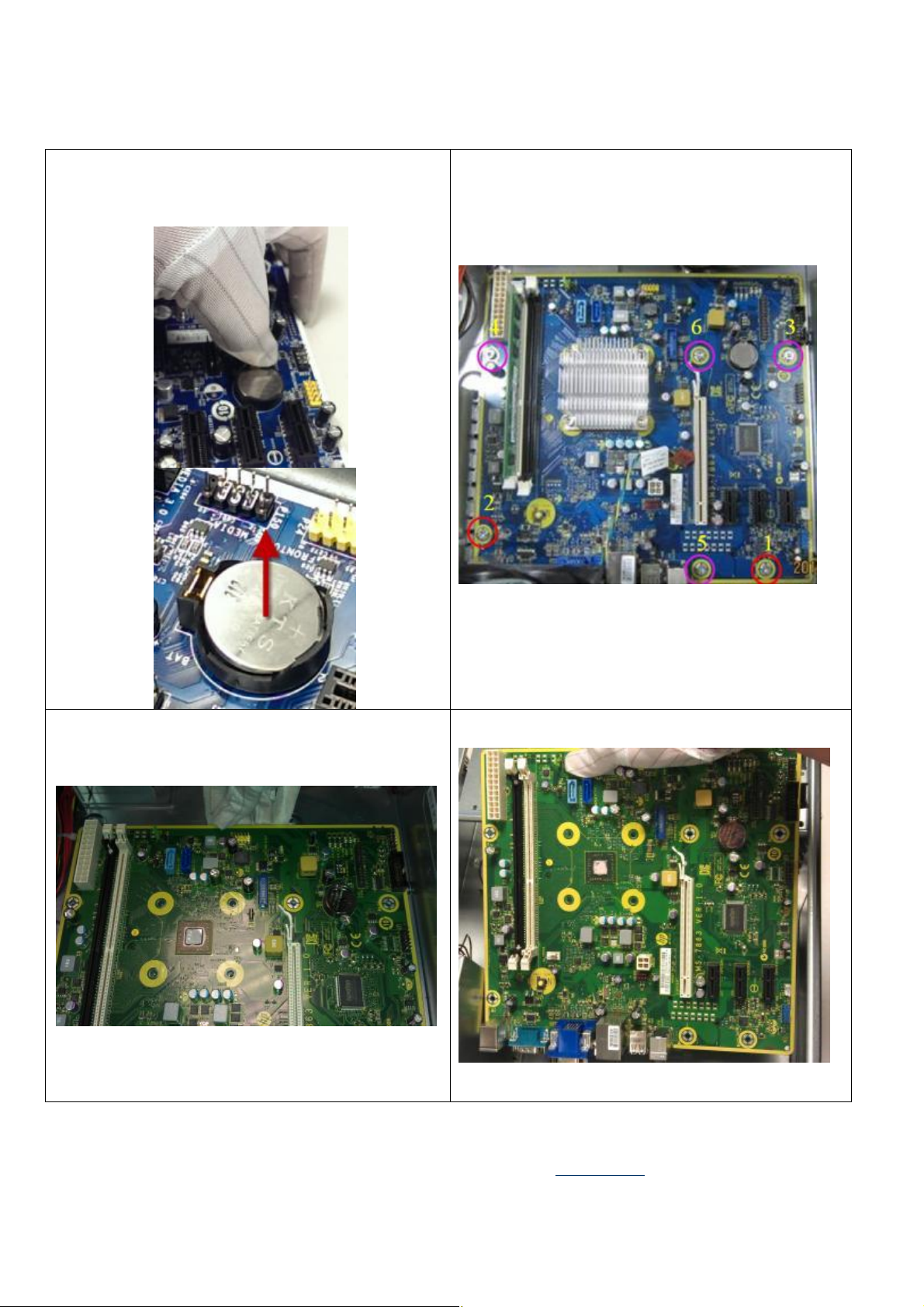
Figure33 Remove the battery from the MB
Figure34 Loose the 6 screws from MB
Figure35 Loose the 8 screws from MB and remove it
Figure36 Remove MB from chassis
EL-MF877-00 Page 11
Template Revision B
PSG instructions for this template are available at EL-MF877-01
Page 12
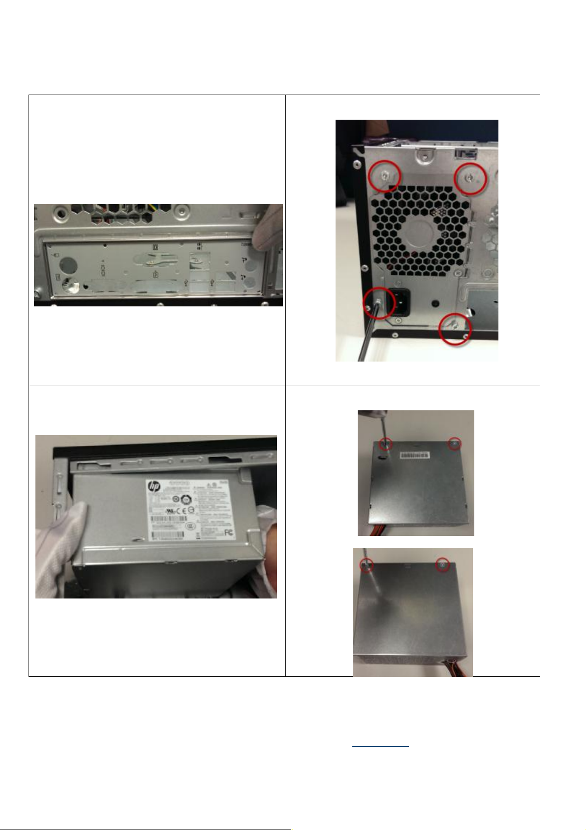
Figure37
Push the
I/O shielding to the inside of the
chassis and remove it
Figure38 Loose 4 screws of PSU and remove it
Figure39 Pull up the PSU and remove it
Figure40 Loose 4 screws from PSU cage and remove it
EL-MF877-00 Page 12
Template Revision B
PSG instructions for this template are available at EL-MF877-01
Page 13
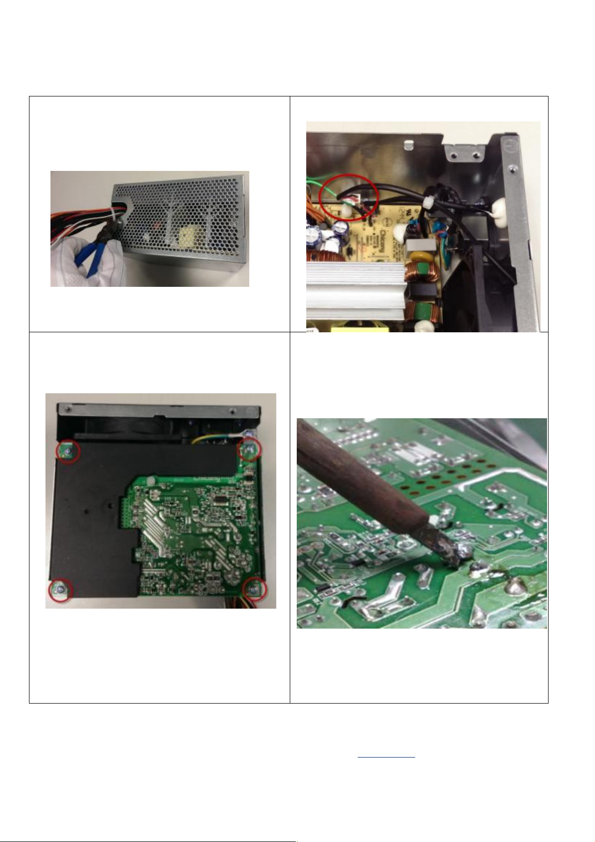
Figure
43 Loose 4 screws from the PSU PCA and remove
Figure
44 Heat the solder of Electrolytic Capacitors
Figure41 Cut the cable tie
it
Figure42Disconnect the fan cable from PSU
greater than 2.5cm in diameter or height and remove it
EL-MF877-00 Page 13
Template Revision B
PSG instructions for this template are available at EL-MF877-01
Page 14
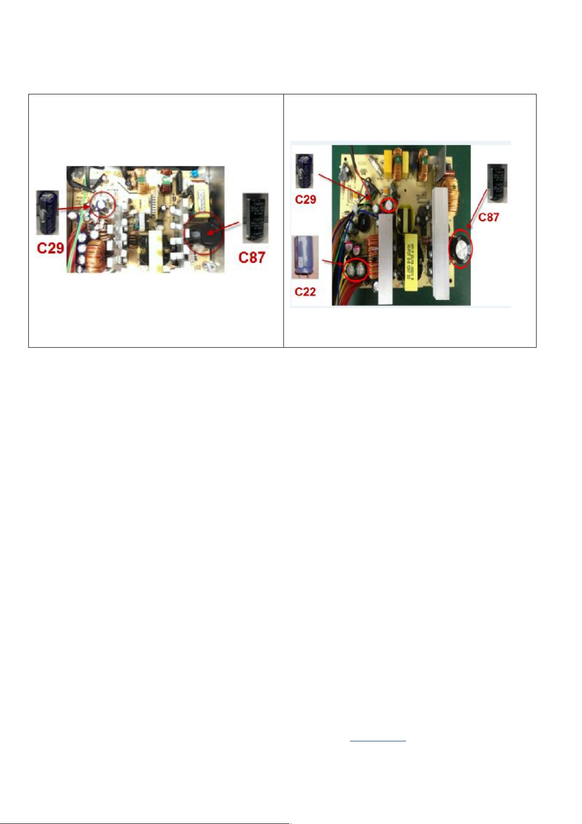
Figure
49 Heat the solder of Electrolytic Capacitors greater
Figure
50 Heat the solder of Electrolytic Capacitors
than 2.5cm in diameter or height and remove it(Gamay
300W E*6 PSU-Bestec)
greater than 2.5cm in diameter or height and remove
it(Gamay 300W E*6 PSU- Acbel))
EL-MF877-00 Page 14
Template Revision B
PSG instructions for this template are available at EL-MF877-01
 Loading...