

HP ProDesk 405 G2 Maintenance And Service Manual

Maintenance and Service Guide
HP ProDesk 405 G2 Microtower

© Copyright 2014 Hewlett-Packard
Development Company, L.P. The information
contained herein is subject to change without
notice.
Intel and Pentium are trademarks of Intel
Corporation in the U.S. and other countries.
Bluetooth is a trademark owned by its
proprietor and used by Hewlett-Packard
Company under license. Microsoft, Windows,
WIndows 7, and Windows 8 are U.S. registered
trademarks of the Microsoft group of
companies. SD Logo is a trademark of its
proprietor.
The only warranties for HP products and
services are set forth in the express warranty
statements accompanying such products and
services. Nothing herein should be construed
as constituting an additional warranty. HP shall
not be liable for technical or editorial errors or
omissions contained herein.
This document contains proprietary
information that is protected by copyright. No
part of this document may be photocopied,
reproduced, or translated to another language
without the prior written consent of HewlettPackard Company.
First Edition (July 2014)
Document Part Number: 7629
11-001
Product notice
This guide describes features that are common
to most models. Some features may not be
available on your computer.
Not all features are available on all editions of
Windows 8. This computer may require
upgraded and/or separately purchased
hardware, drivers, and/or software to take full
advantage of Windows 8 functionality. See
http://www.microsoft.com for details.
This computer may require upgraded and/ or
separately purchased hardware and/or a DVD
drive to install the Windows 7 software and
take full advantage of Windows 7 functionality.
See
http://windows.microsoft.com/en-us/
windows7/get-know-windows-7 for details.

Safety warning notice
WARNING! To reduce the possibility of heat-related injuries or of overheating the device, do not place
the device directly on your lap or obstruct the device air vents. Use the device only on a hard, flat surface. Do
not allow another hard surface, such as an adjoining optional printer, or a soft surface, such as pillows or
rugs or clothing, to block airflow. Also, do not allow the AC adapter to contact the skin or a soft surface, such
as pillows or rugs or clothing, during operation. The device and the AC adapter comply with the useraccessible surface temperature limits defined by the International Standard for Safety of Information
Technology Equipment (IEC 60950).
iii

iv Safety warning notice

Table of contents
1 Product features ........................................................................................................................................... 1
Standard configuration features ........................................................................................................................... 1
Front panel components ....................................................................................................................................... 2
Rear panel components ......................................................................................................................................... 3
Serial number location .......................................................................................................................................... 4
2 Activating and Customizing the Software ........................................................................................................ 5
Activating and customizing the software in Windows 7 ....................................................................................... 5
Activating the Windows operating system ......................................................................................... 5
Downloading Windows 7 updates ....................................................................................................... 5
Installing or upgrading device drivers ................................................................................................ 6
Customizing the monitor display ........................................................................................................ 6
Activating and customizing the software in Windows 8 ....................................................................................... 6
Activating the Windows Operating System ........................................................................................ 6
Downloading Windows 8 updates ....................................................................................................... 6
Customizing the monitor display ........................................................................................................ 7
3 Illustrated parts catalog ................................................................................................................................ 8
Computer major components ................................................................................................................................ 8
Cables ................................................................................................................................................................... 10
Misc parts ............................................................................................................................................................. 11
Drives ................................................................................................................................................................... 13
PCI boards ............................................................................................................................................................ 14
4 Routine care, SATA drive guidelines, and disassembly preparation .................................................................. 15
Electrostatic discharge information ................................................................................................................... 15
Generating static ............................................................................................................................... 15
Preventing electrostatic damage to equipment .............................................................................. 16
Personal grounding methods and equipment .................................................................................. 16
Grounding the work area .................................................................................................................. 16
Recommended materials and equipment ........................................................................................ 17
Operating guidelines ........................................................................................................................................... 17
Routine care ......................................................................................................................................................... 18
General cleaning safety precautions ................................................................................................ 18
Cleaning the Computer Case ............................................................................................................. 18
Cleaning the keyboard ...................................................................................................................... 18
v

Cleaning the monitor ......................................................................................................................... 19
Cleaning the mouse ........................................................................................................................... 19
Service considerations ........................................................................................................................................ 19
Power supply fan ............................................................................................................................... 19
Tools and software Requirements ................................................................................................... 19
Screws ............................................................................................................................................... 20
Cables and connectors ...................................................................................................................... 20
Hard Drives ........................................................................................................................................ 20
Lithium coin cell battery ................................................................................................................... 20
SATA hard drives .................................................................................................................................................. 21
SATA hard drive cables ........................................................................................................................................ 21
SATA data cable ................................................................................................................................. 21
SMART ATA drives ................................................................................................................................................ 21
Cable management .............................................................................................................................................. 21
5 Removal and replacement procedures: Microtower ........................................................................................ 23
Preparation for disassembly ............................................................................................................................... 23
Access panel ........................................................................................................................................................ 24
Front bezel ........................................................................................................................................................... 25
Optical drive bezel blank ..................................................................................................................................... 26
Memory ................................................................................................................................................................ 27
DIMMs ................................................................................................................................................ 27
DDR3-SDRAM DIMMs ......................................................................................................................... 27
Installing DIMMs ................................................................................................................................ 28
Expansion cards ................................................................................................................................................... 29
Drives ................................................................................................................................................................... 33
Drive positions ................................................................................................................................... 35
Removing a slim optical drive ........................................................................................................... 36
Installing a slim optical drive ............................................................................................................ 36
Removing a 3.5-inch hard drive ........................................................................................................ 38
Installing a 3.5-inch hard drive ......................................................................................................... 39
Removing a 2.5-inch hard drive ........................................................................................................ 40
Installing a 2.5-inch hard drive ......................................................................................................... 41
WLAN module ...................................................................................................................................................... 42
RTC battery .......................................................................................................................................................... 45
DisplayPort connector module ............................................................................................................................ 47
Front I/O and power switch assembly ................................................................................................................. 48
Fan sink ................................................................................................................................................................ 50
Speaker ................................................................................................................................................................ 51
Fan ....................................................................................................................................................................... 53
Power supply ....................................................................................................................................................... 55
vi

System board ....................................................................................................................................................... 58
HP ProDesk 405 G2 system board callouts ...................................................................................... 60
6 Computer Setup (F10) Utility ........................................................................................................................ 62
Computer Setup (F10) Utilities ............................................................................................................................ 62
Using Computer Setup (F10) Utilities ............................................................................................... 62
Computer Setup—File ...................................................................................................................... 64
Computer Setup—Storage ............................................................................................................... 65
Computer Setup—Security ............................................................................................................... 66
Computer Setup—Power .................................................................................................................. 68
Computer Setup—Advanced ............................................................................................................ 69
Recovering the Configuration Settings ............................................................................................................... 70
7 Troubleshooting without diagnostics ............................................................................................................ 71
Safety and comfort .............................................................................................................................................. 71
Before you call for technical support .................................................................................................................. 71
Helpful hints ........................................................................................................................................................ 72
Solving general problems ................................................................................................................................... 73
Solving power problems ...................................................................................................................................... 77
Solving hard drive problems ............................................................................................................................... 78
Solving media card reader problems .................................................................................................................. 80
Solving display problems .................................................................................................................................... 81
Solving audio problems ....................................................................................................................................... 85
Solving printer problems ..................................................................................................................................... 87
Solving keyboard and mouse problems ............................................................................................................. 88
Solving Hardware Installation Problems ............................................................................................................ 90
Solving Network Problems .................................................................................................................................. 92
Solving memory problems .................................................................................................................................. 96
Solving CD-ROM and DVD problems .................................................................................................................... 98
Solving USB flash drive problems ..................................................................................................................... 100
Solving front panel component problems ........................................................................................................ 100
Solving Internet access problems ..................................................................................................................... 101
Solving software problems ............................................................................................................................... 102
8 POST error messages ................................................................................................................................. 104
POST numeric codes and text messages .......................................................................................................... 104
Interpreting POST diagnostic front panel LEDs and audible codes .................................................................. 109
9 Password security and resetting CMOS ........................................................................................................ 112
Resetting the password jumper ........................................................................................................................ 112
vii

Changing a Setup or Power-On password ........................................................................................................ 113
Deleting a Setup or Power-On password .......................................................................................................... 114
Clearing and resetting the CMOS ....................................................................................................................... 114
10 HP PC Hardware Diagnostics ..................................................................................................................... 116
Why run HP PC Hardware Diagnostics .............................................................................................................. 116
How to access and run HP PC Hardware Diagnostics ....................................................................................... 116
Downloading HP PC Hardware Diagnostics (UEFI) to a USB device .................................................................. 116
11 System backup and recovery .................................................................................................................... 118
Backing up, restoring, and recovering in Windows 8.1 or Windows 8 ............................................................. 118
Creating recovery media and backups ........................................................................................... 118
Restoring and recovering using Windows tools ............................................................................. 118
Using Reset when the system is not responding ......................................................... 119
Recovery using the Windows recovery USB flash drive ............................................... 119
Recovery using Windows operating system media (purchased separately) .............. 120
Backing up, restoring, and recovering in Windows 7 ........................................................................................ 120
Creating recovery media ................................................................................................................. 121
Creating recovery media using HP Recovery Manager (select models only) .............. 121
Creating recovery discs with HP Recovery Disc Creator (select models only) ............ 122
Creating recovery discs .............................................................................. 122
Backing up your information ........................................................................................ 123
System Restore ............................................................................................................................... 123
System Recovery ............................................................................................................................. 124
System Recovery when Windows is responding .......................................................... 124
System Recovery when Windows is not responding ................................................... 125
System Recovery using recovery media (select models only) .................................... 125
Using HP Recovery Disc operating system discs (select models only) ....................... 126
Appendix A Power cord set requirements ....................................................................................................... 128
General requirements ....................................................................................................................................... 128
Japanese power cord requirements ................................................................................................................. 128
Country-specific requirements ......................................................................................................................... 129
Appendix B Statement of Volatility ................................................................................................................ 130
Appendix C Specifications ............................................................................................................................. 132
Index ........................................................................................................................................................... 134
viii
1 Product features
Standard configuration features
Features may vary depending on the model. For support assistance and to learn more about the hardware
and software installed on your computer model, run the HP Support Assistant utility.
Standard configuration features 1
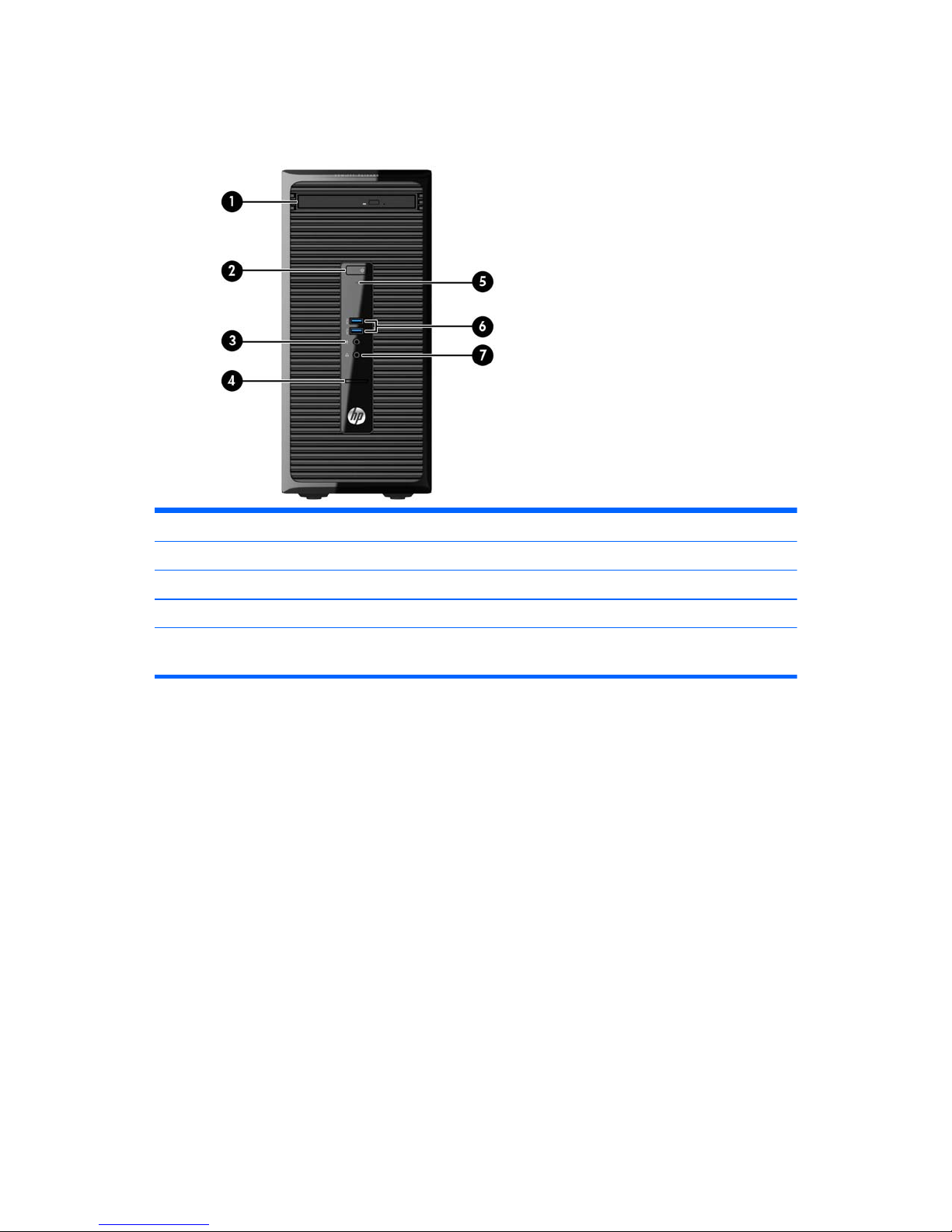
Front panel components
Drive configuration may vary by model. Some models have a bezel blank covering the optical drive bay.
1 Slim Optical Drive (optional) 5 Hard Drive Activity Light
2 Dual-State Power Button 6 USB 3.0 Ports (blue)
3 Microphone Connector 7 Headphone Connector
4SD Card Reader
NOTE: The Power On Light is normally white when the power is on. If it is flashing red, there is a problem with the
computer and it is displaying a diagnostic code.
2 Chapter 1 Product features

Rear panel components
1 Power Cord Connector 7 Voltage Select Switch (included on some
models only)
2
Line-In Audio Connector (blue) 8 Line-Out Connector for powered audio
devices (green)
3
DisplayPort Monitor Connector 9 USB 2.0 Ports (black)
4
Serial Connector 10 VGA Monitor Connector
5
RJ-45 Network Connector 11 PS/2 Keyboard Connector (purple)
6
PS/2 Mouse Connector (green)
NOTE: An optional second serial port and an optional parallel port are available from HP.
The integrated graphics cannot be enabled when a discrete graphics card is installed.
Rear panel components 3

Serial number location
Each computer has a unique serial number and a product ID number that are located on the exterior of the
computer. Keep these numbers available for use when contacting customer service for assistance.
4 Chapter 1 Product features

2 Activating and Customizing the Software
NOTE: This chapter provides information for both Windows 7 and Windows 8.
Activating and customizing the software in Windows 7
If your computer was not shipped with a Windows® operating system, some portions of this documentation
do not apply. Additional information is available in online help after you activate the operating system.
CAUTION: Do not add optional hardware or third-party devices to the computer until the operating system
is successfully activated. Doing so may cause errors and prevent the operating system from installing
properly.
NOTE: Be sure there is a 10.2 cm (4 inch) clearance at the back of the unit and above the monitor to permit
the required airflow.
Activating the Windows operating system
The first time you turn on the computer, the operating system is set up and activated automatically. This
process takes about 5 to 10 minutes. Carefully read and follow the instructions on the screen to complete the
activation.
We recommend that you register your computer with HP during operating system setup so you can receive
important software updates, facilitate support questions, and sign up for special offers.
CAUTION: After the activation process has begun, DO NOT TURN OFF THE COMPUTER UNTIL THE PROCESS IS
COMPLETE. Turning off the computer during the activation process may damage the software that runs the
computer or prevent its proper installation.
NOTE: If the computer shipped with more than one operating system language on the hard drive, the
activation process could take up to 60 minutes.
Downloading Windows 7 updates
Microsoft may release updates to the operating system. To help keep the computer running optimally, HP
recommends checking for the latest updates during the initial installation and periodically throughout the life
of the computer.
1. To set up your Internet connection, click Start > Internet Explorer and follow the instructions on the
screen.
2. After an Internet connection has been established, click the Start > All Programs > Windows Update.
3. Run Windows Update monthly thereafter.
Activating and customizing the software in Windows 7 5

Installing or upgrading device drivers
When installing optional hardware devices after the operating system installation is complete, you must also
install the drivers for each of the devices.
In Windows 7, if prompted for the i386 directory, replace the path specification with C:\i386, or use the
Browse button in the dialog box to locate the i386 folder. This action points the operating system to the
appropriate drivers.
Obtain the latest support software, including support software for the operating system, from
http://www.hp.com/support. Select your country and language, select Download drivers and software (and
firmware), enter the model number of the computer, and press Enter.
Customizing the monitor display
If you wish, you can select or change the monitor refresh rates, screen resolution, color settings, font sizes,
and power management settings.
For more information, refer to the online documentation provided with the graphics controller utility or the
documentation that came with your monitor.
Right-click on the Windows desktop, then click Personalize to change display settings.
Activating and customizing the software in Windows 8
Additional information is available in online help after you activate the operating system.
NOTE: Be sure there is a 10.2 cm (4 inch) clearance at the back of the unit and above the monitor to permit
the required airflow.
Activating the Windows Operating System
The first time you turn on the computer, the operating system is set up and activated automatically. This
process takes about 5 to 10 minutes. Carefully read and follow the instructions on the screen to complete the
activation.
We recommend that you register your computer with HP during operating system set up so you can receive
important software updates, facilitate support questions, and sign up for special offers. You can also register
your computer with HP using the Register with HP app on the Start screen.
CAUTION: After the activation process has begun, DO NOT TURN OFF THE COMPUTER UNTIL THE PROCESS IS
COMPLETE. Turning off the computer during the activation process may damage the software that runs the
computer or prevent its proper installation.
Downloading Windows 8 updates
Microsoft may release updates to the operating system. To help keep the computer running optimally, HP
recommends checking for the latest updates during the initial installation and periodically throughout the life
of the computer.
Run Windows Update as soon as possible after you set up your computer.
1. Point to the upper-right or lower-right corner of the Start screen to display the charms.
2. Click Settings > Change PC Settings > Windows Update.
3. Run Windows Update monthly thereafter.
6 Chapter 2 Activating and Customizing the Software

Customizing the monitor display
You can customize display settings for Windows 8 separately for the Start screen and the Desktop.
To customize the Start screen:
1. Point to the upper-right or lower-right corner of the Start screen to display the charms.
2. Click Settings > Change PC Settings.
3. Click Personalize to change the display settings.
To customize the Desktop:
1. Click the Desktop app on the Start screen.
2. Right-click on the desktop, and then click Personalize to change display settings.
Activating and customizing the software in Windows 8 7
3 Illustrated parts catalog
NOTE: HP continually improves and changes product parts. For complete and current information on
supported parts for your computer, go to
http://partsurfer.hp.com, select your country or region, and then
follow the on-screen instructions.
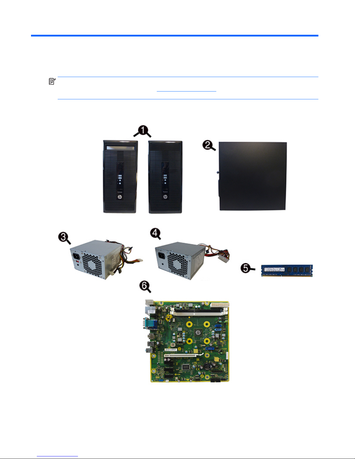
Computer major components
8 Chapter 3 Illustrated parts catalog

Item Description
(1) Front bezel
For use in all countries and regions except for the People’s Republic of China
For use in the People’s Republic of China
(2) Access panel
Power supply
(3) 300W, Active PFC + SEPA
(4) 180W, regular
180W, Energy Star 5.0
180W, Active PFC
(5) Memory modules (PC3,12800, CL11)
8-GB
4-GB
2-GB
System board (includes replacement thermal material)
(6) System board with AMD Quad-Core A8-6410 Accelerated Processor with AMD Radeon HD 8400 Discrete-Class Graphics
(2.4GHz, 2MB L2 cache, 25W)
For use in models without Windows 8.1
For use in models with Windows 8.1 Standard
For use in models with Windows 8.1 Professional
For use in models with NetClone (the People’s Republic of China only)
System board with AMD Quad-Core A4-6250 Accelerated Processor with AMD Radeon HD 8330 Discrete-Class Graphics
(2.0GHz, 2MB L2 cache, 25W)
For use in models without Windows 8.1
For use in models with Windows 8.1 Standard
For use in models with Windows 8.1 Professional
For use in models with NetClone (the People’s Republic of China only)
System board with AMD Dual-Core E1-6050 Accelerated Processor with AMD Radeon HD 8240 Discrete-Class Graphics
(2.0GHz, 1MB L2 cache, 25W)
For use in models without Windows 8.1
For use in models with Windows 8.1 Standard
For use in models with Windows 8.1 Professional
For use in models with NetClone (the People’s Republic of China only)
Computer major components 9

Cables
Item Description
(1) SATA data cable, hard drive, 10 inch, two straight ends
(2) SATA data cable, 10 inch, one straight end, one right angled end
SATA data cable, 14 inch, two straight ends
DisplayPort cable
DMS-59 to dual VGA cable
DMS-59 to dual DVI cable
Adapters
USB 3.0-to-USB 2.0 (200 mm)
USB 3.0-to-USB 2.0 (China only)
DisplayPort to VGA
DisplayPort to DVI
DisplayPort to HDMI
DVI to VGA
DVI-I to VGA (BFR/PVC free)
DVI-I to VGA (Standard)
10 Chapter 3 Illustrated parts catalog
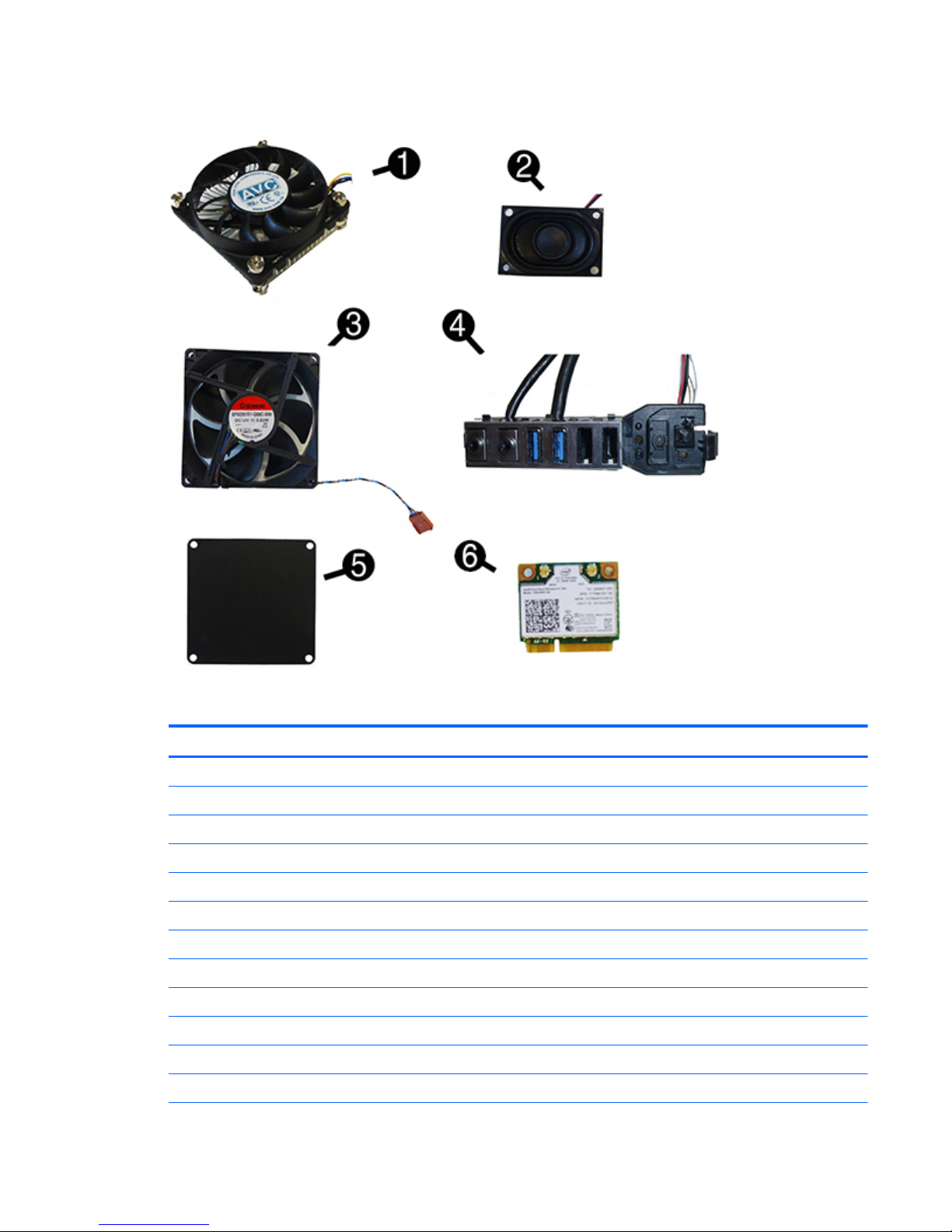
Misc parts
Item Description
(1) Fan sink (includes replacement thermal material)
Standard
BFR/PVC free
(2) Speaker
(3) Fan
(4) Front I/O assembly
(5) Fan vent cover for use in models without a chassis fan
(6) WLAN modules
HP WLAN 802.11 a/b/g/n + Bluetooth 4.0
Intel Dual Band Wireless-N 7260NB 802.11 a/b/g/n 2x2 WiFi + BT4.0
Card reader
Optical drive bezel blank
Misc parts 11

Item Description
Grommet (hard drive screw, blue)
WLAN antennas
Clamp lock
HP Ultraslim Keyed Cable Lock
Thin USB powered speakers
HP Webcam, 720p
Drive adapters:
Hard drive carrier, 2.5-inch to 3.5-inch
Removable frame carrier (installs in optical drive bay; includes adapter for 2.5-inch hard drives)
Mouse
PS2, optical
USB, optical
USB, laser
Washable
Keyboards
PS/2
USB
USB, unbranded, Katydid
Smart card, CCID
Wireless keyboard, mouse, and dongle kit (for use in all countries except for Brazil)
Washable
12 Chapter 3 Illustrated parts catalog

Drives
Description
Hard drives and solid-state drives (SSDs)
2 TB, 7200 rpm, 3.5 inch
1 TB, hybrid SSD, 2.5-inch
1 TB, 7200 rpm, 3.5 inch
500 GB, 10000 rpm
500 GB, 7200 rpm, 2.5 inch, self-encrypting (SED)
500 GB, hybrid SSD, 2.5 inch
500 GB, 7200 rpm, 3.5 inch
500 GB, 7200 rpm, 2.5 inch
256 GB Solid-state Drive (SSD), self-encrypting (SED)
256 GB Solid-state Drive (SSD)
180 GB Solid-state Drive (SSD)
128 GB Solid-state Drive (SSD), self-encrypting (SED)
128 GB Solid-state Drive (SSD)
120 GB Solid-state Drive (SSD)
Optical drive
Blu-ray BD-RW SuperMulti XL Drive
DVD±RW drive
DVD-ROM drive
Drives 13
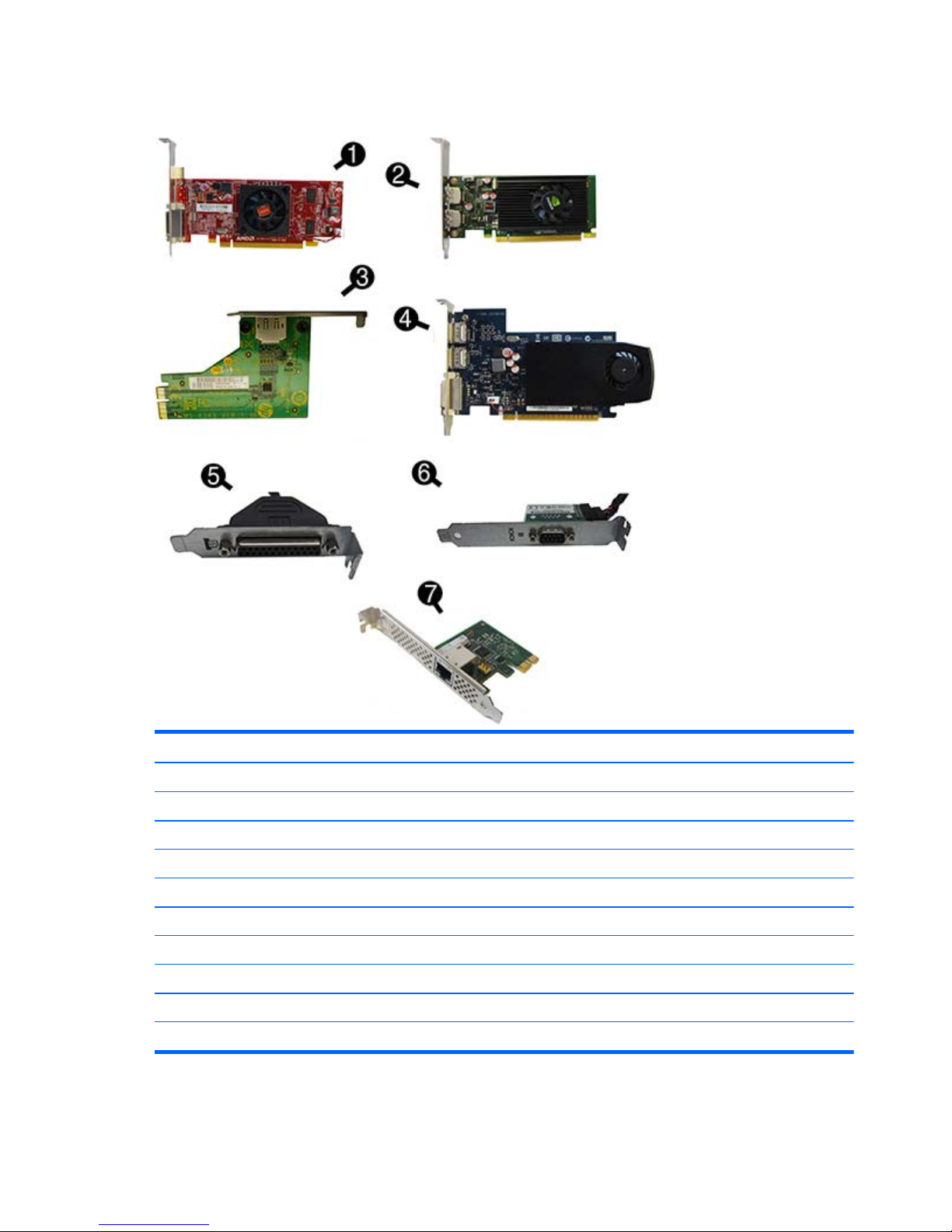
PCI boards
Description
(1) AMD Radeon HD8350 DH PCIe x16 graphics card, 1 GB
(2) Nvidia NVS310 PCIe x16 graphics card, 512 MB
Nvidia NVS315 PCIe x16 graphics card, 1 GB
AMD Radeon HD8490 DP PCIe x16 graphics card, 1 GB
AMD Radeon HD8470 PCIe x16 graphics card, 2 GB (for use only in the People’s Republic of China)
(3) DisplayPort connector module
(4) Nvidia GeForce GT630 DP PCIe x16 graphics card, 2 GB
(5) Printer port, PCI card
(6) Serial port, PCI card
(7) Intel PRO/1000 single port GbE NIC, includes bracket
14 Chapter 3 Illustrated parts catalog

4 Routine care, SATA drive guidelines, and
disassembly preparation
This chapter provides general service information for the computer. Adherence to the procedures and
precautions described in this chapter is essential for proper service.
CAUTION: When the computer is plugged into an AC power source, voltage is always applied to the system
board. You must disconnect the power cord from the power source before opening the computer to prevent
system board or component damage.
Electrostatic discharge information
A sudden discharge of static electricity from your finger or other conductor can destroy static-sensitive
devices or microcircuitry. Often the spark is neither felt nor heard, but damage occurs. An electronic device
exposed to electrostatic discharge (ESD) may not appear to be affected at all and can work perfectly
throughout a normal cycle. The device may function normally for a while, but it has been degraded in the
internal layers, reducing its life expectancy.
Networks built into many integrated circuits provide some protection, but in many cases, the discharge
contains enough power to alter device parameters or melt silicon junctions.
Generating static
The following table shows that:
●
Different activities generate different amounts of static electricity.
●
Static electricity increases as humidity decreases.
Relative Humidity
Event 55% 40% 10%
Walking across carpet
Walking across vinyl floor
Motions of bench worker
Removing DIPs from plastic tube
7,500 V
3,000 V
400 V
400 V
15,000 V
5,000 V
800 V
700 V
35,000 V
12,000 V
6,000 V
2,000 V
Removing DIPs from vinyl tray
Removing DIPs from Styrofoam
Removing bubble pack from PCB
Packing PCBs in foam-lined box
2,000 V
3,500 V
7,000 V
5,000 V
4,000 V
5,000 V
20,000 V
11,000 V
11,500 V
14,500 V
26,500 V
21,000 V
These are then multi-packaged inside plastic tubes, trays, or Styrofoam.
NOTE: 700 volts can degrade a product.
Electrostatic discharge information 15

Preventing electrostatic damage to equipment
Many electronic components are sensitive to ESD. Circuitry design and structure determine the degree of
sensitivity. The following packaging and grounding precautions are necessary to prevent damage to electric
components and accessories.
●
To avoid hand contact, transport products in static-safe containers such as tubes, bags, or boxes.
●
Protect all electrostatic parts and assemblies with conductive or approved containers or packaging.
●
Keep electrostatic sensitive parts in their containers until they arrive at static-free stations.
●
Place items on a grounded surface before removing them from their container.
●
Always be properly grounded when touching a sensitive component or assembly.
●
Avoid contact with pins, leads, or circuitry.
●
Place reusable electrostatic-sensitive parts from assemblies in protective packaging or conductive
foam.
Personal grounding methods and equipment
Use the following equipment to prevent static electricity damage to equipment:
●
Wrist straps are flexible straps with a maximum of one-megohm ± 10% resistance in the ground cords.
To provide proper ground, a strap must be worn snug against bare skin. The ground cord must be
connected and fit snugly into the banana plug connector on the grounding mat or workstation.
●
Heel straps/Toe straps/Boot straps can be used at standing workstations and are compatible with
most types of shoes or boots. On conductive floors or dissipative floor mats, use them on both feet with
a maximum of one-megohm ± 10% resistance between the operator and ground.
Static Shielding Protection Levels
Method Voltage
Antistatic plastic
Carbon-loaded plastic
Metallized laminate
1,500
7,500
15,000
Grounding the work area
To prevent static damage at the work area, use the following precautions:
●
Cover the work surface with approved static-dissipative material. Provide a wrist strap connected to the
work surface and properly grounded tools and equipment.
●
Use static-dissipative mats, foot straps, or air ionizers to give added protection.
●
Handle electrostatic sensitive components, parts, and assemblies by the case or PCB laminate. Handle
them only at static-free work areas.
●
Turn off power and input signals before inserting and removing connectors or test equipment.
●
Use fixtures made of static-safe materials when fixtures must directly contact dissipative surfaces.
●
Keep work area free of nonconductive materials such as ordinary plastic assembly aids and Styrofoam.
●
Use field service tools, such as cutters, screwdrivers, and vacuums, that are conductive.
16 Chapter 4 Routine care, SATA drive guidelines, and disassembly preparation

Recommended materials and equipment
Materials and equipment that are recommended for use in preventing static electricity include:
●
Antistatic tape
●
Antistatic smocks, aprons, or sleeve protectors
●
Conductive bins and other assembly or soldering aids
●
Conductive foam
●
Conductive tabletop workstations with ground cord of one-megohm +/- 10% resistance
●
Static-dissipative table or floor mats with hard tie to ground
●
Field service kits
●
Static awareness labels
●
Wrist straps and footwear straps providing one-megohm +/- 10% resistance
●
Material handling packages
●
Conductive plastic bags
●
Conductive plastic tubes
●
Conductive tote boxes
●
Opaque shielding bags
●
Transparent metallized shielding bags
●
Transparent shielding tubes
Operating guidelines
To prevent overheating and to help prolong the life of the computer:
●
Keep the computer away from excessive moisture, direct sunlight, and extremes of heat and cold.
●
Operate the computer on a sturdy, level surface. Leave a 10.2-cm (4-inch) clearance on all vented sides
of the computer and above the monitor to permit the required airflow.
●
Never restrict the airflow into the computer by blocking any vents or air intakes. Do not place the
keyboard, with the keyboard feet down, directly against the front of the desktop unit as this also
restricts airflow.
●
Occasionally clean the air vents on all vented sides of the computer. Lint, dust, and other foreign matter
can block the vents and limit the airflow. Be sure to unplug the computer before cleaning the air vents.
●
Never operate the computer with the cover or side panel removed.
●
Do not stack computers on top of each other or place computers so near each other that they are
subject to each other’s re-circulated or preheated air.
●
If the computer is to be operated within a separate enclosure, intake and exhaust ventilation must be
provided on the enclosure, and the same operating guidelines listed above will still apply.
●
Keep liquids away from the computer and keyboard.
Operating guidelines 17

●
Never cover the ventilation slots on the monitor with any type of material.
●
Install or enable power management functions of the operating system or other software, including
sleep states.
Routine care
General cleaning safety precautions
1. Never use solvents or flammable solutions to clean the computer.
2. Never immerse any parts in water or cleaning solutions; apply any liquids to a clean cloth and then use
the cloth on the component.
3. Always unplug the computer when cleaning with liquids or damp cloths.
4. Always unplug the computer before cleaning the keyboard, mouse, or air vents.
5. Disconnect the keyboard before cleaning it.
6. Wear safety glasses equipped with side shields when cleaning the keyboard.
Cleaning the Computer Case
Follow all safety precautions in General cleaning safety precautions on page 18 before cleaning the
computer.
To clean the computer case, follow the procedures described below:
●
To remove light stains or dirt, use plain water with a clean, lint-free cloth or swab.
●
For stronger stains, use a mild dishwashing liquid diluted with water. Rinse well by wiping it with a cloth
or swab dampened with clear water.
●
For stubborn stains, use isopropyl (rubbing) alcohol. No rinsing is needed as the alcohol will evaporate
quickly and not leave a residue.
●
After cleaning, always wipe the unit with a clean, lint-free cloth.
●
Occasionally clean the air vents on the computer. Lint and other foreign matter can block the vents and
limit the airflow.
Cleaning the keyboard
Follow all safety precautions in General cleaning safety precautions on page 18 before cleaning the
keyboard.
To clean the tops of the keys or the keyboard body, follow the procedures described in
Cleaning the
Computer Case on page 18.
When cleaning debris from under the keys, review all rules in
General cleaning safety precautions on page 18
before following these procedures:
CAUTION: Use safety glasses equipped with side shields before attempting to clean debris from under the
keys.
●
Visible debris underneath or between the keys may be removed by vacuuming or shaking.
●
Canned, pressurized air may be used to clean debris from under the keys. Caution should be used as too
much air pressure can dislodge lubricants applied under the wide keys.
18 Chapter 4 Routine care, SATA drive guidelines, and disassembly preparation

●
If you remove a key, use a specially designed key puller to prevent damage to the keys. This tool is
available through many electronic supply outlets.
CAUTION: Never remove a wide leveled key (like the space bar) from the keyboard. If these keys are
improperly removed or installed, the keyboard may not function properly.
●
Cleaning under a key may be done with a swab moistened with isopropyl alcohol and squeezed out. Be
careful not to wipe away lubricants necessary for proper key functions. Use tweezers to remove any
fibers or dirt in confined areas. Allow the parts to air dry before reassembly.
Cleaning the monitor
●
Wipe the monitor screen with a clean cloth moistened with water or with a towelette designed for
cleaning monitors. Do not use sprays or aerosols directly on the screen; the liquid may seep into the
housing and damage a component. Never use solvents or flammable liquids on the monitor.
●
To clean the monitor body follow the procedures in
Cleaning the Computer Case on page 18.
Cleaning the mouse
Before cleaning the mouse, ensure that the power to the computer is turned off.
●
Clean the mouse ball by first removing the retaining plate and the ball from the housing. Pull out any
debris from the ball socket and wipe the ball with a clean, dry cloth before reassembly.
●
To clean the mouse body, follow the procedures in
Cleaning the Computer Case on page 18.
Service considerations
Listed below are some of the considerations that you should keep in mind during the disassembly and
assembly of the computer.
Power supply fan
The power supply fan is a variable-speed fan based on the temperature in the power supply.
CAUTION: The cooling fan is always on when the computer is in the “On” mode. The cooling fan is off when
the computer is in “Standby,” “Suspend,” or “Off” modes.
You must disconnect the power cord from the power source before opening the computer to prevent system
board or component damage.
Tools and software Requirements
To service the computer, you need the following:
●
Torx T-15 screwdriver
●
Torx T-15 screwdriver with small diameter shank (for certain front bezel removal)
●
Flat-bladed screwdriver (may sometimes be used in place of the Torx screwdriver)
●
Phillips #2 screwdriver
●
Diagnostics software
●
Tamper-resistant T-15 wrench
Service considerations 19

Screws
The screws used in the computer are not interchangeable. They may have standard or metric threads and
may be of different lengths. If an incorrect screw is used during the reassembly process, it can damage the
unit. HP strongly recommends that all screws removed during disassembly be kept with the part that was
removed, then returned to their proper locations.
CAUTION: Metric screws have a black finish. U.S. screws have a silver finish and are used on hard drives
only.
CAUTION: As each subassembly is removed from the computer, it should be placed away from the work
area to prevent damage.
Cables and connectors
Most cables used throughout the unit are flat, flexible cables. These cables must be handled with care to
avoid damage. Apply only the tension required to seat or unseat the cables during insertion or removal from
the connector. Handle cables by the connector whenever possible. In all cases, avoid bending or twisting the
cables, and ensure that the cables are routed in such a way that they cannot be caught or snagged by parts
being removed or replaced.
CAUTION: When servicing this computer, ensure that cables are placed in their proper location during the
reassembly process. Improper cable placement can damage the computer.
Hard Drives
Handle hard drives as delicate, precision components, avoiding all physical shock and vibration. This applies
to failed drives as well as replacement spares.
●
If a drive must be mailed, place the drive in a bubble-pack mailer or other suitable protective packaging
and label the package “Fragile: Handle With Care.”
●
Do not remove hard drives from the shipping package for storage. Keep hard drives in their protective
packaging until they are actually mounted in the computer.
●
Avoid dropping drives from any height onto any surface.
●
If you are inserting or removing a hard drive, turn off the computer. Do not remove a hard drive while
the computer is on or in standby mode.
●
Before handling a drive, ensure that you are discharged of static electricity. While handling a drive,
avoid touching the connector.
●
Do not use excessive force when inserting a drive.
●
Avoid exposing a hard drive to liquids, temperature extremes, or products that have magnetic fields
such as monitors or speakers.
Lithium coin cell battery
The battery that comes with the computer provides power to the real-time clock and has a minimum lifetime
of about three years.
See the appropriate removal and replacement chapter for the chassis you are working on in this guide for
instructions on the replacement procedures.
WARNING! This computer contains a lithium battery. There is a risk of fire and chemical burn if the battery
is handled improperly. Do not disassemble, crush, puncture, short external contacts, dispose in water or fire,
or expose it to temperatures higher than 140ºF (60ºC). Do not attempt to recharge the battery.
20 Chapter 4 Routine care, SATA drive guidelines, and disassembly preparation

NOTE: Batteries, battery packs, and accumulators should not be disposed of together with the general
household waste. In order to forward them to recycling or proper disposal, please use the public collection
system or return them to HP, their authorized partners, or their agents.
SATA hard drives
Serial ATA Hard Drive Characteristics
Number of pins/conductors in data cable 7/7
Number of pins in power cable 15
Maximum data cable length 39.37 in (100 cm)
Data interface voltage differential 400-700 mV
Drive voltages 3.3 V, 5 V, 12 V
Jumpers for configuring drive N/A
Data transfer rate 6.0 Gb/s
SATA hard drive cables
SATA data cable
Always use an HP approved SATA 6.0 Gb/s cable as it is fully backwards compatible with the SATA 1.5 Gb/s
drives.
Current HP desktop products ship with SATA 6.0 Gb/s hard drives.
SATA data cables are susceptible to damage if overflexed. Never crease a SATA data cable and never bend it
tighter than a 30 mm (1.18 in) radius.
The SATA data cable is a thin, 7-pin cable designed to transmit data for only a single drive.
SMART ATA drives
The Self Monitoring Analysis and Recording Technology (SMART) ATA drives for the HP Personal Computers
have built-in drive failure prediction that warns the user or network administrator of an impending failure or
crash of the hard drive. The SMART drive tracks fault prediction and failure indication parameters such as
reallocated sector count, spin retry count, and calibration retry count. If the drive determines that a failure is
imminent, it generates a fault alert.
Cable management
Always follow good cable management practices when working inside the computer.
●
Keep cables away from major heat sources like the heat sink.
●
Do not jam cables on top of expansion cards or memory modules. Printed circuit cards like these are not
designed to take excessive pressure on them.
●
Keep cables clear of sliding or moveable parts to prevent them from being cut or crimped when the
parts are moved.
●
When folding a flat ribbon cable, never fold to a sharp crease. Sharp creases may damage the wires.
SATA hard drives 21

●
Some flat ribbon cables come prefolded. Never change the folds on these cables.
●
Do not bend any cable sharply. A sharp bend can break the internal wires.
●
Never bend a SATA data cable tighter than a 30 mm (1.18 in) radius.
●
Never crease a SATA data cable.
●
Do not rely on components like the drive cage, power supply, or computer cover to push cables down
into the chassis. Always position the cables to lay properly by themselves.
22 Chapter 4 Routine care, SATA drive guidelines, and disassembly preparation
 Loading...