

HP ProDesk 400 G3 MT, EliteDesk 705 G2 MT Hardware Reference Manual

Hardware Reference Guide
HP ProDesk 400 G3 MT Business PC

© Copyright 2015 HP Development Company,
L.P.
Microsoft and Windows are either registered
trademarks or trademarks of Microsoft
Corporation in the United States and/or other
countries.
The information contained herein is subject to
change without notice. The only warranties for
HP products and services are set forth in the
express warranty statements accompanying
such products and services. Nothing herein
should be construed as constituting an
additional warranty. HP shall not be liable for
technical or editorial errors or omissions
contained herein.
First Edition: July 2015
Document part number: 822842-001
Product notice
This guide describes features that are common
to most models. Some features may not be
available on your computer.
Not all features are available in all editions of
Windows 8. This computer may require
upgraded and/or separately purchased
hardware, drivers and/or software to take full
advantage of Windows 8 functionality. See
http://www.microsoft.com for details.
This computer may require upgraded and/or
separately purchased hardware and/or a DVD
drive to install the Windows 7 software and
take full advantage of Windows 7 functionality.
See http://windows.microsoft.com/en-us/
windows7/get-know-windows-7 for details.
Software terms
By installing, copying, downloading, or
otherwise using any software product
preinstalled on this computer, you agree to be
bound by the terms of the HP End User License
Agreement (EULA). If you do not accept these
license terms, your sole remedy is to return the
entire unused product (hardware and
software) within 14 days for a refund subject
to the refund policy of your place of purchase.
For any further information or to request a full
refund of the computer, please contact your
local point of sale (the seller).

About This Book
This guide provides basic information for upgrading the HP ProDesk Business PC.
WARNING! Text set off in this manner indicates that failure to follow directions could result in bodily harm
or loss of life.
CAUTION: Text set off in this manner indicates that failure to follow directions could result in damage to
equipment or loss of information.
NOTE: Text set off in this manner provides important supplemental information.
iii

iv About This Book

Table of contents
1 Product features ........................................................................................................................................... 1
Standard configuration features ........................................................................................................................... 1
Front panel components ....................................................................................................................................... 2
Rear panel components ......................................................................................................................................... 3
Serial number location .......................................................................................................................................... 4
2 Hardware upgrades ....................................................................................................................................... 5
Serviceability features ........................................................................................................................................... 5
Warnings and cautions .......................................................................................................................................... 5
Removing the computer access panel .................................................................................................................. 6
Replacing the computer access panel ................................................................................................................... 7
Removing the front bezel ...................................................................................................................................... 8
Removing an optical drive bezel blank ................................................................................................................. 9
Replacing the front bezel ...................................................................................................................................... 9
System board connections .................................................................................................................................. 10
Installing additional memory .............................................................................................................................. 11
DIMMs ................................................................................................................................................ 11
DDR4-SDRAM DIMMs ......................................................................................................................... 11
Populating DIMM sockets .................................................................................................................. 11
Installing DIMMs ................................................................................................................................ 12
Removing or installing an expansion card .......................................................................................................... 14
Drive positions ..................................................................................................................................................... 18
Removing and Installing drives ........................................................................................................................... 19
Removing a 9.5mm slim optical drive .............................................................................................. 20
Installing a 9.5mm slim optical drive ............................................................................................... 21
Removing a 3.5-inch hard drive ........................................................................................................ 23
Installing a 3.5-inch hard drive ......................................................................................................... 24
Removing a 2.5-inch hard drive ........................................................................................................ 25
Installing a 2.5-inch hard drive ......................................................................................................... 26
Installing a security lock ...................................................................................................................................... 28
Cable lock .......................................................................................................................................... 28
Padlock .............................................................................................................................................. 28
HP Business PC Security Lock V2 ...................................................................................................... 29
Appendix A Battery replacement ..................................................................................................................... 34
v

Appendix B Electrostatic discharge .................................................................................................................. 37
Preventing electrostatic damage ........................................................................................................................ 37
Grounding methods ............................................................................................................................................. 37
Appendix C Computer operating guidelines, routine care and shipping preparation ............................................. 38
Computer operating guidelines and routine care ............................................................................................... 38
Optical drive precautions .................................................................................................................................... 39
Operation ........................................................................................................................................... 39
Cleaning ............................................................................................................................................. 39
Safety ................................................................................................................................................ 39
Shipping preparation ........................................................................................................................................... 39
Appendix D Accessibility ................................................................................................................................. 40
Supported assistive technologies ....................................................................................................................... 40
Contacting support .............................................................................................................................................. 40
Index ............................................................................................................................................................. 41
vi
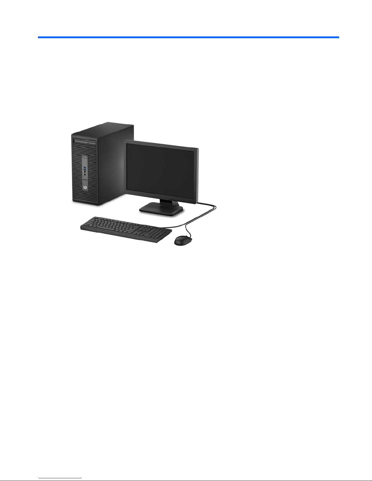
1 Product features
Standard configuration features
Features may vary depending on the model. For support assistance and to learn more about the hardware
and software installed on your computer model, run the HP Support Assistant utility.
Standard configuration features 1
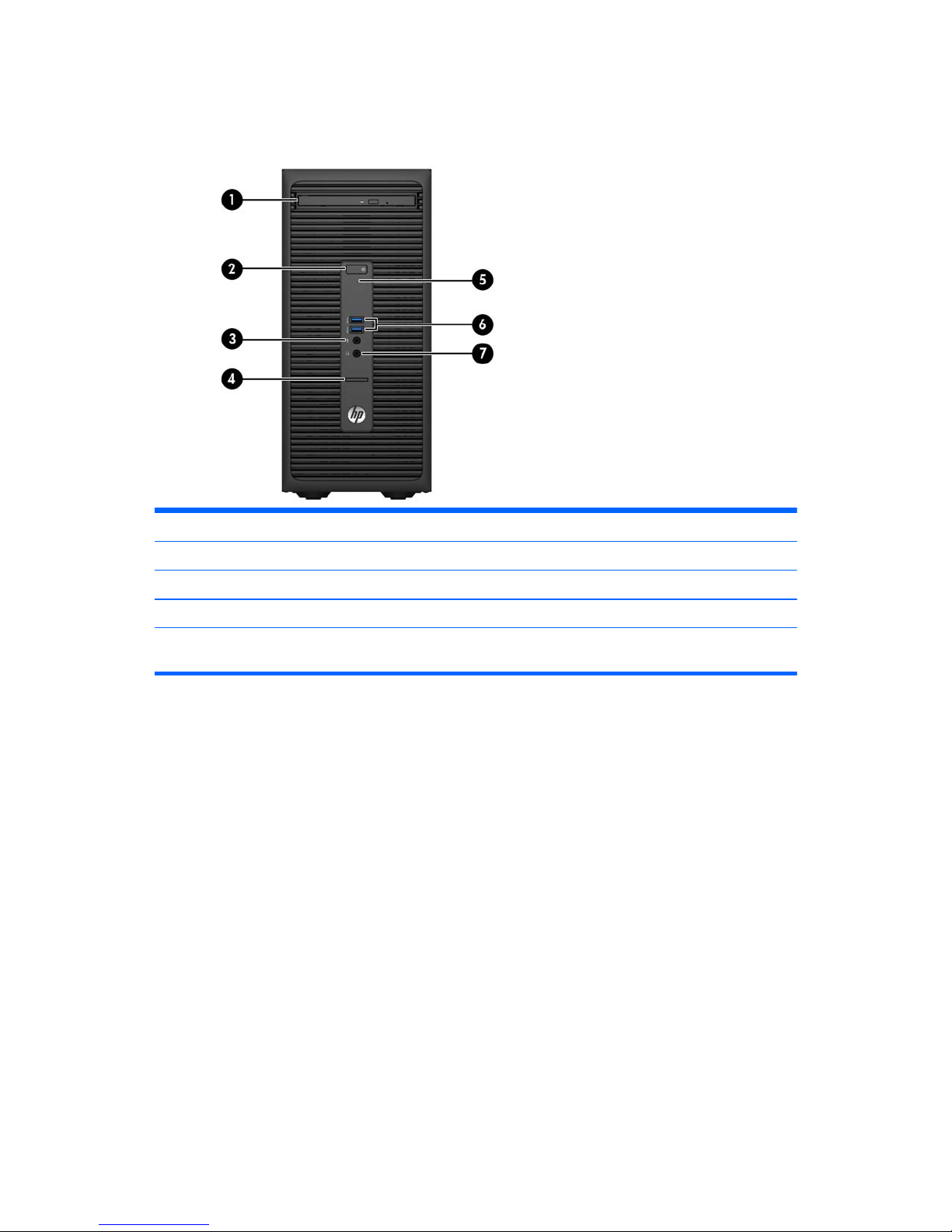
Front panel components
Drive configuration may vary by model. Some models have a bezel blank covering the optical drive bay.
1 Slim Optical Drive (optional) 5 Hard Drive Activity Light
2 Dual-State Power Button 6 USB 3.0 Ports (blue)
3 Microphone Connector 7 Headphone Connector
4SD Card Reader (optional)
NOTE: The Power On Light is normally white when the power is on. If it is flashing red, there is a problem with the
computer and it is displaying a diagnostic code. Refer to the Maintenance and Service Guide to interpret the code.
2 Chapter 1 Product features
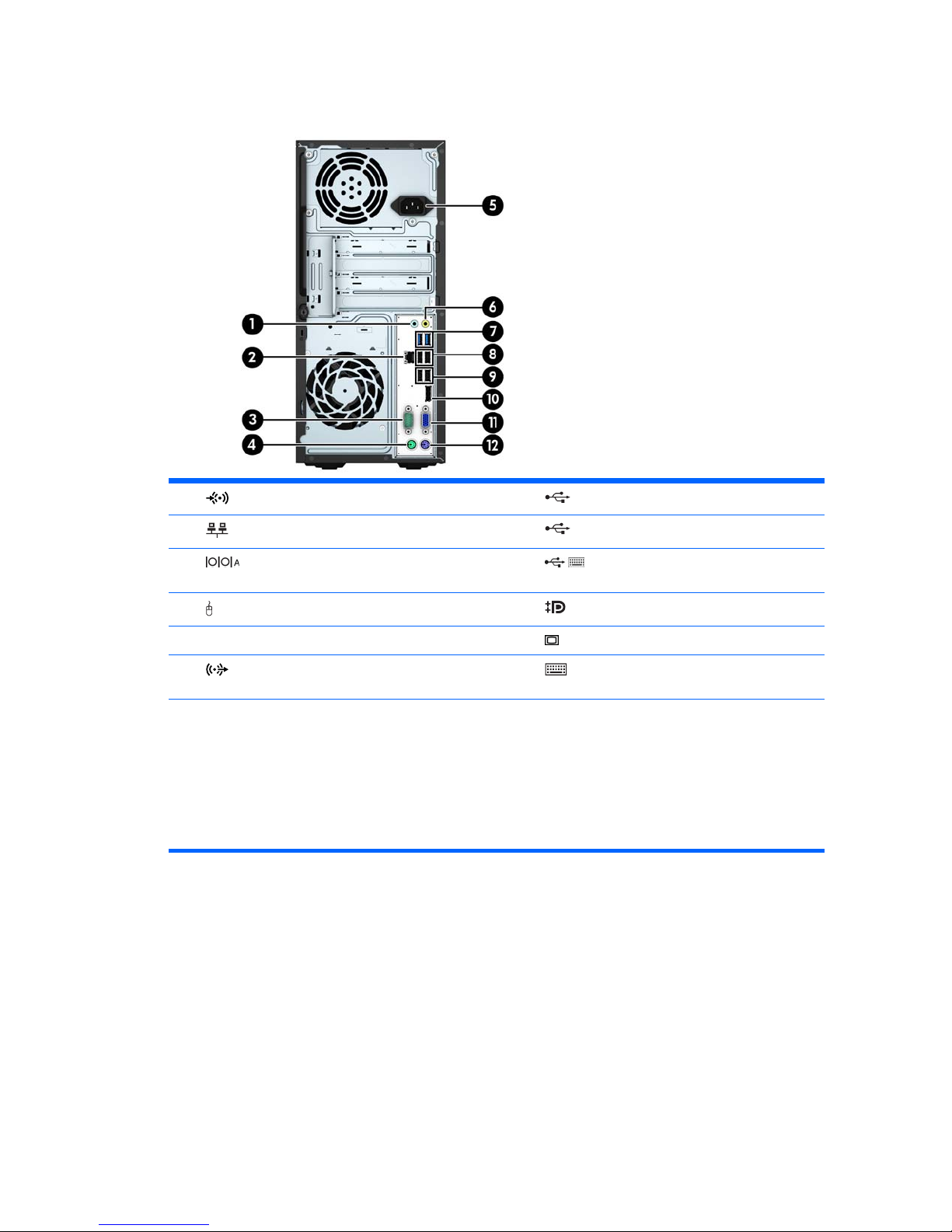
Rear panel components
1 Line-In Audio Connector (blue) 7 USB 3.0 Ports (blue)
2
RJ-45 Network Connector 8 USB 2.0 Ports (black)
3
Serial Connector 9 USB 2.0 Ports with Wake from S4/S5
feature (black)
4
PS/2 Mouse Connector (green) 10 DisplayPort Monitor Connector
5 Power Cord Connector 11
VGA Monitor Connector
6
Line-Out Connector for powered audio devices
(green)
12 PS/2 Keyboard Connector (purple)
NOTE: An optional second serial port and an optional parallel port are available from HP.
If using a USB keyboard, HP recommends connecting the keyboard to one of the USB 2.0 ports with the wake from S4/S5
feature. The wake from S4/S5 feature is also supported on the PS/2 connectors if enabled in BIOS F10 Setup.
When a graphics card is installed in one of the system board slots, the video connectors on the graphics card and the
integrated graphics on the system board may be used at the same time. However, for such a configuration, only the display
connected to the discrete graphics card will display POST messages.
The system board graphics can be disabled by changing settings in Computer Setup.
Rear panel components 3
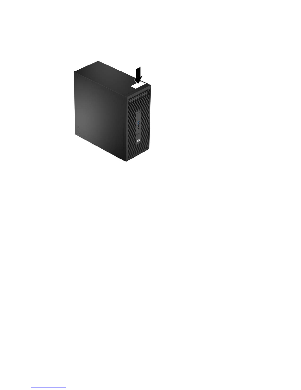
Serial number location
Each computer has a unique serial number and a product ID number that are located on the exterior of the
computer. Keep these numbers available for use when contacting customer service for assistance.
4 Chapter 1 Product features

2 Hardware upgrades
Serviceability features
The computer includes features that make it easy to upgrade and service. A Torx T15 or flathead screwdriver
is needed for many of the installation procedures described in this chapter.
Warnings and cautions
Before performing upgrades be sure to carefully read all of the applicable instructions, cautions, and
warnings in this guide.
WARNING! To reduce the risk of personal injury from electrical shock, hot surfaces, or fire:
Disconnect the power cord from the wall outlet and allow the internal system components to cool before
touching.
Do not plug telecommunications or telephone connectors into the network interface controller (NIC)
receptacles.
Do not disable the power cord grounding plug. The grounding plug is an important safety feature.
Plug the power cord in a grounded (earthed) outlet that is easily accessible at all times.
To reduce the risk of serious injury, read the Safety & Comfort Guide. It describes proper workstation, setup,
posture, and health and work habits for computer users, and provides important electrical and mechanical
safety information. This guide is located on the Web at
http://www.hp.com/ergo.
WARNING! Energized and moving parts inside.
Disconnect power to the equipment before removing the enclosure.
Replace and secure the enclosure before re-energizing the equipment.
CAUTION: Static electricity can damage the electrical components of the computer or optional equipment.
Before beginning these procedures, ensure that you are discharged of static electricity by briefly touching a
grounded metal object. See
Electrostatic discharge on page 37 for more information.
When the computer is plugged into an AC power source, voltage is always applied to the system board. You
must disconnect the power cord from the power source before opening the computer to prevent damage to
internal components.
Serviceability features 5
Removing the computer access panel
To access internal components, you must remove the access panel:
1. Remove/disengage any security devices that prohibit opening the computer.
2. Remove all removable media, such as compact discs or USB flash drives, from the computer.
3. Turn off the computer properly through the operating system, then turn off any external devices.
4. Disconnect the power cord from the power outlet and disconnect any external devices.
CAUTION: Regardless of the power-on state, voltage is always present on the system board as long as
the system is plugged into an active AC outlet. You must disconnect the power cord to avoid damage to
the internal components of the computer.
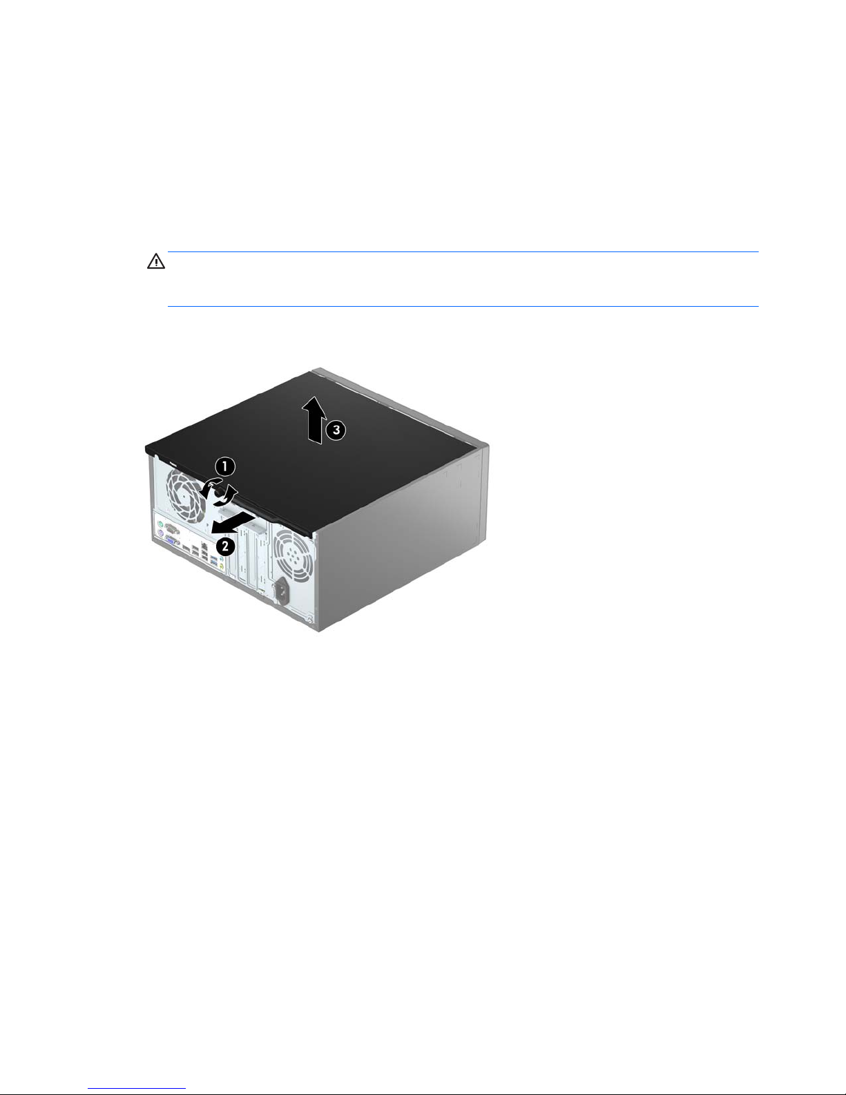
5. Loosen the thumbscrew on the rear of the computer (1), and then slide the panel back (2) and lift if off
the computer (3).
6 Chapter 2 Hardware upgrades
Replacing the computer access panel
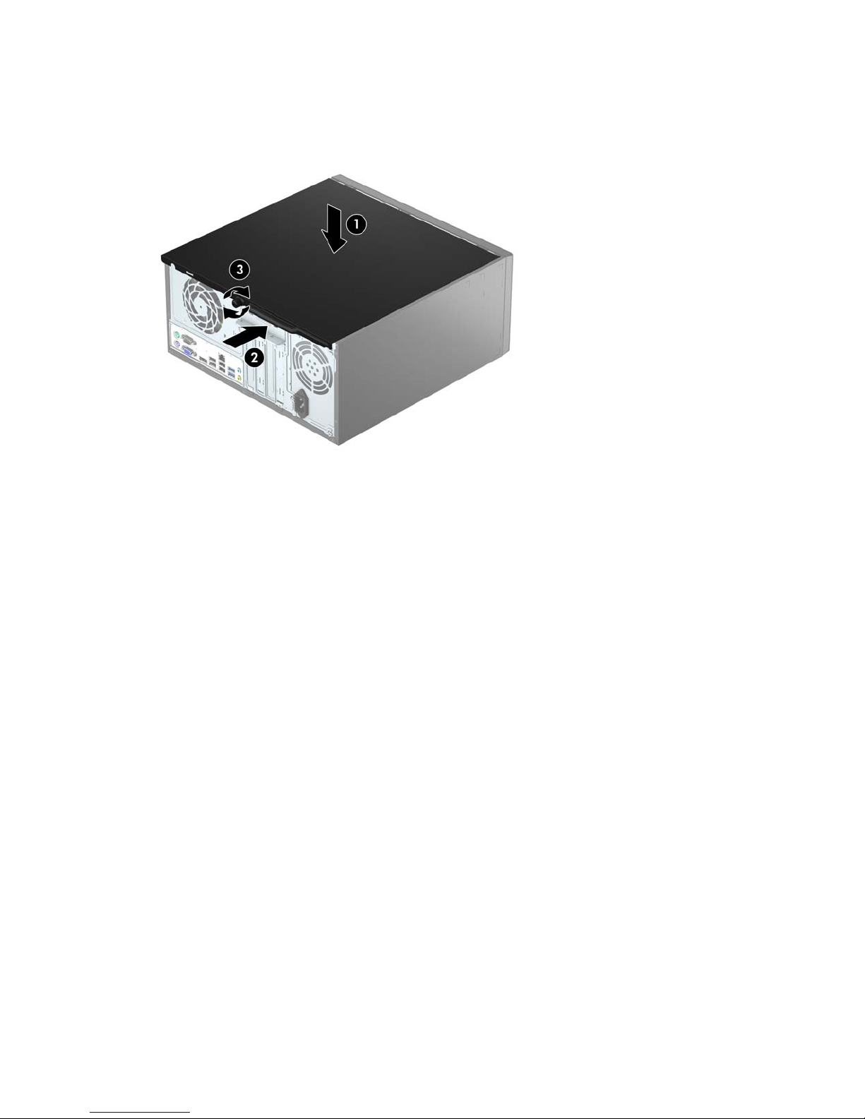
Place the panel on the computer (1), and then slide it forward (2) and tighten the thumbscrew (3) to secure
the panel in place.
Replacing the computer access panel 7
Removing the front bezel
1. Remove/disengage any security devices that prohibit opening the computer.
2. Remove all removable media, such as compact discs or USB flash drives, from the computer.
3. Turn off the computer properly through the operating system, then turn off any external devices.
4. Disconnect the power cord from the power outlet and disconnect any external devices.
CAUTION: Regardless of the power-on state, voltage is always present on the system board as long as
the system is plugged into an active AC outlet. You must disconnect the power cord to avoid damage to
the internal components of the computer.
5. Remove the computer access panel.
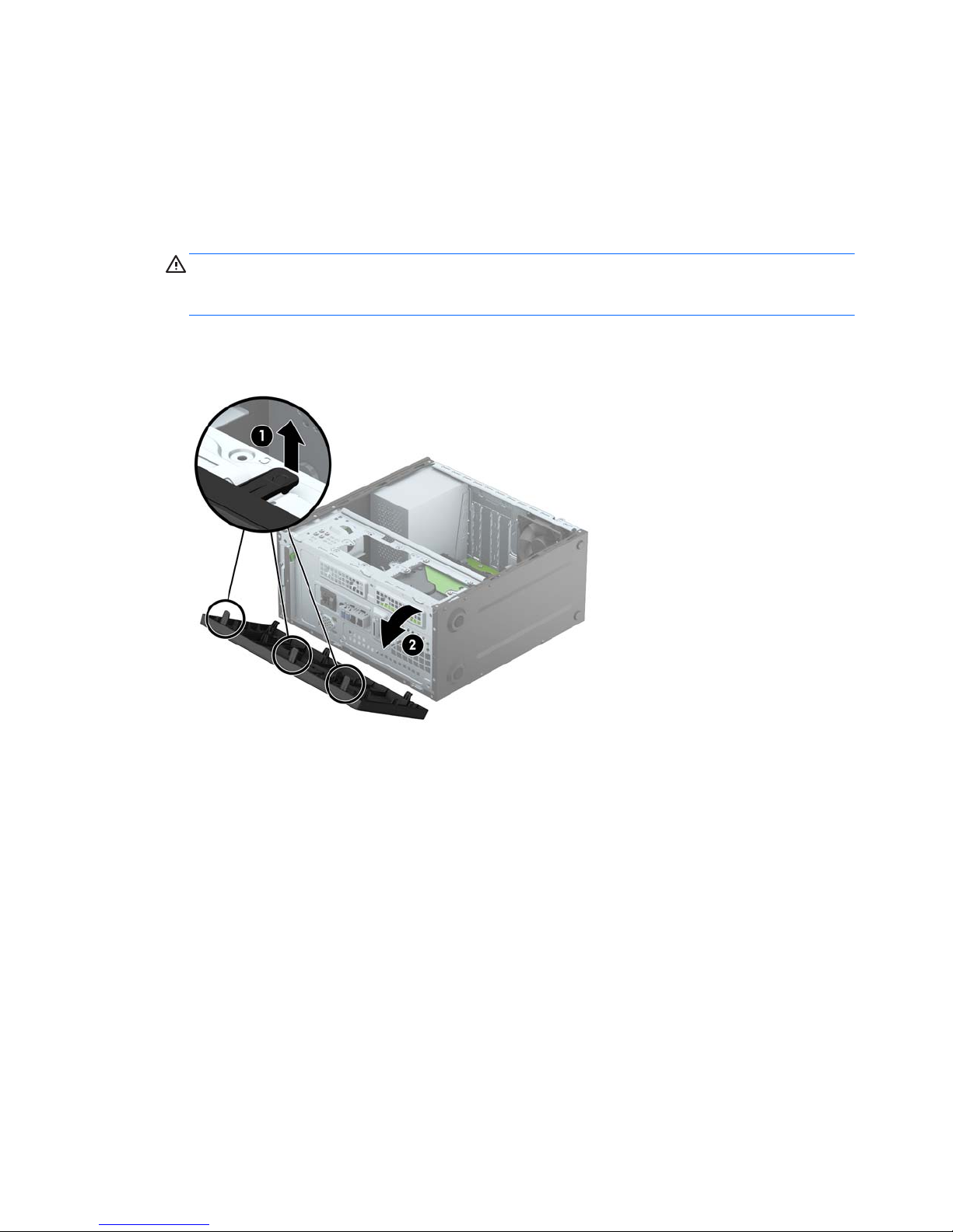
6. Lift up the three tabs on the side of the bezel (1), and then rotate the bezel off the chassis (2).
8 Chapter 2 Hardware upgrades
Removing an optical drive bezel blank
On some models, there is a bezel blank covering the slim optical drive bay. Remove the bezel blank before
installing an optical drive. To remove the bezel blank:
1. Remove the computer access panel and front bezel.
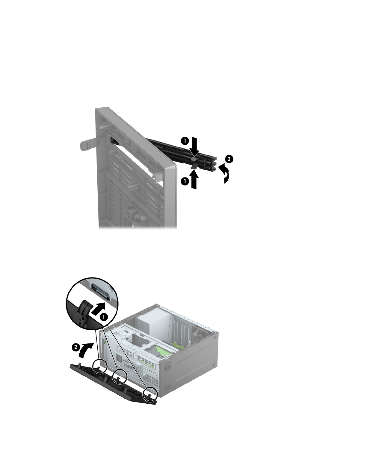
2. To remove the bezel blank, press upward on the bottom tab and press downward on the top tab on the
side of the blank (1), and then rotate the blank off the front of the bezel (2).
Replacing the front bezel
Insert the three hooks on the bottom edge of the bezel into the rectangular holes on the chassis (1), and then
rotate the top side of the bezel onto the chassis (2) and snap it into place.
Removing an optical drive bezel blank 9
 Loading...