

HP ProCurve 745wl, ProCUrve Secure Access 700wl, ProCurve XL Installation And Getting Started Manual
Page 1
Installation and
Getting Started Guide
ProCurve Secure Access 700wl Series
www.procurve.com
Page 2

Page 3

PROCURVE
SECURE ACCESS 700WL SERIES
INSTALLATION AND GETTING
STARTED GUIDE
Page 4

© Copyright 2004, 2006 Hewlett-Packard Development
Company, L.P. The information contained herein is
subject to change without notice.
Publication Number
5991-4756
June, 2006
Edition 1
Applicable Products
ProCurve Access Control Server 745wl (J9038A)
ProCurve XL Access Controller Module (J8162A)
Trademark Credits
Windows NT®, Windows®, and MS Windows® are US
registered trademarks of Microsoft Corporation.
Disclaimer
The only warranties for HP products and services are set
forth in the express warranty statements accompanying such
products and services. Nothing herein should be construed
as constituting an additional warranty. HP shall not be liable
for technical or editorial errors or omissions contained
herein.
Warranty
See the Customer Support/Warranty booklet included with
the product.
A copy of the specific warranty terms applicable to your
Hewlett-Packard products and replacement parts can be
obtained from your HP Sales and Service Office or
authorized dealer.
ii
Page 5

CONTENTS
Preface vii
Audience vii
Document Objectives vii
Organization vii
Related Publications ix
Document Conventions ix
Support Information ix
Compliance and Safety Notices ix
Chapter 1 Introduction to the ProCurve 700wl Series 1-1
Overview 1-1
Centralized Administration of the 700wl Series system 1-1
Order of Network Installation 1-2
Access Control Server with One or More Access Controller
Modules 1-2
Redundant Access Control Servers with One or More Access
Controller Modules 1-2
Tools and Information Required 1-3
Chapter 2 Hardware Installation 2-1
Hardware Description 2-1
System Memory/Storage 2-2
Chassis 2-2
Power Supply 2-2
Fans 2-2
I/O Ports 2-2
Controls and Indicators 2-3
Rear Chassis 2-4
Site Planning Checklist 2-4
Site Power Requirements and Heat Dissipation 2-5
Installing a 700wl Series System 2-6
Unpacking 2-6
iii
Page 6

Rack Mounting the Chassis 2-6
Connecting Power to the Chassis 2-7
Chapter 3 Network Setup 3-1
Getting Started 3-1
Access Control Server Setup 3-2
IP Addressing Considerations 3-2
Initial Configuration Using the CLI 3-3
Initial Configuration Using the Administrative Console 3-8
Access Controller Module Setup 3-14
IP Addressing Considerations 3-14
Initial Configuration Using the CLI 3-15
Completing the Installation 3-15
Chapter 4 Basic Configuration 4-1
Procedure Overview 4-1
Preparation 4-2
Creating a User Account in the Built-In Database 4-2
User Authentication Through the Default Logon Page 4-3
PPTP Gateway Configuration 4-4
Configuring Access Policies for Encryption 4-5
PPTP Client Configuration 4-8
User Authentication Via PPTP Connection 4-11
External Authentication Service Configuration 4-11
Verify the External Authentication Service 4-15
Appendix A Troubleshooting A-1
Appendix B LCD Display Description B-1
Display Description B-1
Button Functionality B-1
Powering On and System Boot B-2
Default Display B-2
Main Menus B-2
System Shutdown B-3
Appendix C Technical Specifications, Safety and Compliance C-1
Technical Specifications C-1
Environmental Ranges C-1
iv Installation and Getting Started Guide
Page 7

Power Requirements C-1
Physical Dimensions C-1
Safety and Regulatory Compliance C-2
Physical Interface C-2
Appendix D Cable and Connector Specifications D-1
Serial Console Port D-1
10/100 Downlink Ethernet Cables D-2
Power Crossover Connector D-2
Appendix E Safety and EMC Regulatory Statements E-1
Safety Information E-1
U.S.A. E-9
Canada E-9
Australia/New Zealand E-9
Japan E-9
Korea E-9
BSMI E-10
Regulatory Model Identification Number E-10
European Community E-11
Appendix F Recycle Statements F-1
Waste Electrical and Electronic Equipment (WEEE) Statements F-1
Index IX-1
Installation and Getting Started Guide v
Page 8

Page 9

PREFACE
This preface describes the objective, audience, use, and organization of the Installation and Getting Started
Guide. It also outlines the document conventions, related documentation, and support information.
Audience
The audience for this document is the network administrator who wants to enable network users to
communicate using the 700wl Series system. This document is intended for authorized personnel who
have previous experience working with network telecommunications systems or similar equipment. It is
assumed that the personnel using this document have the appropriate background and knowledge to
complete the procedures described in this document.
Document Objectives
This document contains procedural information describing the installation and configuration of the
ProCurve Access Control Server 745wl and XL Access Controller Module. Each procedure is written in a
task-oriented format consisting of numbered step-by-step instructions. In most cases, several procedures
are required to complete one overall task. All procedures should be performed in the order they appear in
this document, unless otherwise instructed.
This document also provides instructions for the creation of a basic configuration of the ProCurve Secure
Access 700wl Series that allows a user to:
• Connect to the 700wl Series system (optionally using the PPTP secure protocol)
• Log in and be authenticated through the ProCurve 700wl Series built-in database
• Pass IP traffic and have access to network resources.
A system running with this configuration is suitable for basic evaluation or demonstration purposes.
Organization
This document is organized as follows:
Chapter 1— Introduction
This chapter gives an overview of the 700wl Series system installation procedure.
vii
Page 10

Chapter 2— Hardware Installation
This chapter describes the installation of the ProCurve Access Control Server 745wl. Installation of the XL
Access Controller Module is described in the ProCurve Series 5300xl Switches Installation and Getting Started
Guide.
Chapter 3— Network Setup
This chapter describes the network configuration of the Access Control Server after it has been physically
installed.
Chapter 4—Basic Configuration
This chapter leads you through the configuration of a basic system setup that includes user accounts and
user authentication, as well as a PPTP gateway, and support for an external authentication service. such
as LDAP.
Appendix A—Troubleshooting
This chapter presents troubleshooting procedures for the 700wl Series system.
Appendix B—LCD Display Description
This appendix describes the LCD display on the Access Control Server 745wl. The display can be used to
view the system’s network parameters, and to power down the system.
Appendix C—Technical Specifications, Safety and Compliance
This appendix describes the technical specifications of the system, and provides safety and compliance
information.
Appendix D—Cable and Connector Specifications
This appendix describes the Serial Connector and the Standard Ethernet cables for use with the 700wl Series
system.
Appendix E—Safety and EMC Regulatory Statements
This appendix describes safety and EMC regulatory information for the 700wl Series system.
Appendix F—Recycle Statements
This appendix describes Waste Electrical and Electronic Equipment (WEEE) information for the 700wl
Series system.
viii ProCurve Secure Access 700wl Series Installation and Getting Started Guide
Page 11
Related Publications
The following publications provide additional information:
• ProCurve Secure Access 700wl Series Management and Configuration Guide
• ProCurve 700wl Series Release Notes
• ProCurve Series 5300xl Switches Installation and Getting Started Guide
Document Conventions
The following text conventions are used in this document:
Convention Definition
Boldface Arial Screen menus that you click to select, field names, and commands that
you select are in boldface Arial.
Italic Palatino New terms that are defined in the text, and emphasized terms are in italic
Palatino.
Courier Filenames and commands or text that you type are in Courier.
The following icons are used to alert you to important information:
Icon Notice Type Alerts you to...
None Note Helpful suggestions or information that is of special importance in
certain situations.
None Caution Risk of personal injury, loss of system functionality, or loss of data.
Warning Risk of severe personal injury, system damage, or irrecoverable
loss of data.
Support Information
See the ProCurve Networking web site at www.procurve.com. Click on technical support and select
support services for a list of available support resources and options for contacting HP.
Compliance and Safety Notices
Technical specifications, safety information, and regulatory compliance statements can be found in
Appendix C, “Technical Specifications”. This information should be read thoroughly before installing
the HP system equipment.
ProCurve Secure Access 700wl Series Installation and Getting Started Guide ix
Page 12

Page 13

INTRODUCTION TO THE PROCURVE
1
700WL SERIES
This chapter gives a brief description of the installation procedures for ProCurve 700wl Series products. It
consists of the following sections
Overview . . . . . . . . . . . . . . . . . . . . . . . . . . . . . . . . . . . . . . . . . . . . . . . . . . . . . . . . . . . . . . . . . . 1-1
Order of Network Installation . . . . . . . . . . . . . . . . . . . . . . . . . . . . . . . . . . . . . . . . . . . . . . . . . 1-2
Tools and Information Required . . . . . . . . . . . . . . . . . . . . . . . . . . . . . . . . . . . . . . . . . . . . . . . 1-3
Overview
Two products make up the ProCurve 700wl Series:
• ProCurve Access Control Server 745wl
• ProCurve XL Access Controller Module
The physical installation of the Access Control Server 745wl is described fully in Chapter 2, “Hardware
Installation”. The hardware installation is always performed first, before the network installation. The XL
Access Controller Module is installed in the 5300xl switches, and, therefore, its installation is described in
the ProCurve Series 5300xl Switches Installation and Getting Started Guide.
Centralized Administration of the 700wl Series system
Wireless network clients physically connect through Access Controller Modules, but authentication and
rights administration for these clients is handled centrally from the Access Control Server. In addition, all
configuration of the Access Controller Modules connected to the system is handled by the Administrative
Console located in the Access Control Server. Once you have installed an Access Controller Module onto
your network, you should not need to perform any administration functions directly on the Access
Controller Module.
From the centralized Administrative Console on your Access Control Server you can perform the
following configuration functions:
• Configure the 700wl Series system setup, including bridging, DHCP Network for NAT Clients,
Forwarding of IP Address broadcasts, setting up HTTP proxies, configuring SNMP settings, and
setting the system date & time
• Update the 700wl Series system software or return to a previous version
• Set up a Wireless Data Privacy policy for clients using VPN protocols
• Set up Authentication Policies for how users authenticate themselves to the system
• Set up Access Policies to control what users can do over the network
1-1
Page 14

Introduction to the ProCurve 700wl Series
• Set up Identity Profiles to put users in groups that share the same access policies
• Set up Connection Profiles that allow you to specify different Access Policies for users based on
location, time of day, VLAN tags, and Authentication Policies
• Set up redundant Access Control Servers to provide failover
Additionally, the Administrative Console provides functions for monitoring the status of the system
components, as well as monitoring clients logged onto the system and their sessions.
Order of Network Installation
The order of installation depends on the complement of equipment you wish to install. There are two
basic configurations, and for each, there is an order of network installation as follows:
• Access Control Server 745wl with at least one XL Access Controller Module
• Two redundant Access Control Server 745wls with at least one XL Access Controller Module
Access Control Server with One or More Access Controller Modules
If you are installing one Access Control Server 745wl and one or more XL Access Controller Modules,
perform installation in the following order:
Step 1. Install the Access Control Server, following the steps in Chapter 2, “Hardware Installation” in this
manual.
Step 2. Perform the network setup for the Access Control Server, following the steps in “Access Control
Server Setup” on page 3-2.
Step 3. Install the Access Controller Modules following the steps in the ProCurve Series 5300xl Switches
Installation and Getting Started Guide.
Step 4. Once the Access Controller Modules are recognized by the Access Control Server and appear in
the Access Control Server Administrative Console, perform any additional setup required,
following the steps in“Completing the Installation” on page 3-15.
Redundant Access Control Servers with One or More Access Controller Modules
Step 1. Install each Access Control Server, following the steps in Chapter 2, “Hardware Installation” in
this manual.
Note: It is strongly recommended that an Access Control Server 745wl be used as the
secondary Access Control Server. If you use an Access Control Server 740wl as the redundant
Access Control Server, transferring the primary 745wl workload to a secondary 740wl may
result in the working integrity being compromised due to 740wl limitations.
Step 2. Perform the network setup for each Access Control Server, following the steps in“Access Control
Server Setup” on page 3-2.
1-2 ProCurve Secure Access 700wl Series Installation and Getting Started Guide
Page 15

Introduction to the ProCurve 700wl Series
Note the IP address and shared secret of the Access Control Server that you plan to designate as
the Primary Access Control Server. Do not configure the Access Control Servers (yet) as
redundant peers.
Step 3. Install the Access Controller Modules following the steps in the ProCurve Series 5300xl Switches
Installation and Getting Started Guide.
Configure the Access Controller Modules with the IP address and shared secret of the Primary
Access Control Server.
Step 4. Once the Access Controller Module is recognized by the Primary Access Control Server and
appears in the Access Control Server Administrative Console, perform any additional setup
required, following the steps in “Completing the Installation” on page 3-15.
Step 5. On the Access Control Server that is to be the redundant (non-Primary) Access Control Server, set
the shared secret to be the same as the Primary Access Control Server.
Step 6. On the Primary Access Control Server, configure redundancy, following the steps in Chapter 6,
“Configuring the Network” in the ProCurve Secure Access 700wl Series Management and
Configuration Guide.
Tools and Information Required
To perform network installation for an Access Control Server or Access Controller Module, the
information defined in Table 1-1 may be required:
Note: The information you gather here is required during configuration and is presented here as a
reminder to find it before beginning the network installation.
Table 1-1. Installation Parameters
Parameter Form
Hostname (Fully-Qualified) Not required. Must be fully-qualified if provided.
Example: am21b.corp.com
Note: A hostname is required only for Access Control Servers that will have a
real Secure Socket Layer (SSL) certificate installed. If you install a signed SSL
certificate, the hostname must match that on the SSL certificate.
Domain name Defines the system’s domain if a hostname is not provided. This is optional.
Example: xyzcorp.com
IP address Can be configured as a static IP address or can be obtained via DHCP.
Note: The IP address of the Access Control Server will be needed to configure
Access Controller Modules.
Subnet Mask Defines the system’s subnet range. Can be obtained via DHCP. Example:
255.255.255.0.
Gateway (router) IP address Defines the default router. Can be obtained via DHCP.
Primary and Secondary DNS
server IP addresses
ProCurve Secure Access 700wl Series Installation and Getting Started Guide 1-3
Defines the location of the primary and backup DNS servers. Can be obtained
via DHCP.
Page 16

Introduction to the ProCurve 700wl Series
Table 1-1. Installation Parameters
Parameter Form
Shared Secret Secret key used to establish trust relationship between an Access Control
Server and an Access Controller Module. Alphanumeric string. The same
shared secret must be configured on each system.
Many of these parameters can be supplied by the DHCP server if the system is configured to obtain its IP
address via DHCP. If the system is configured to use a static IP address, then all the parameters shown in
the table must be provided when the system is configured for the network.
The following tools and equipment are required to install a 700wl Series system in a rack:
• Tape measure and level
• Number 2 Phillips screwdriver
1-4 ProCurve Secure Access 700wl Series Installation and Getting Started Guide
Page 17
HARDWARE INSTALLATION
This chapter describes the hardware installation of the ProCurve Access Control Server 745wl. (The XL
Access Controller Module is installed in the 5300xl switches, and, therefore, its installation is described in
the ProCurve Series 5300xl Switches Installation and Getting Started Guide.) You must be sure that the site
requirements are met and carefully follow the procedures described to physically install the equipment.
This chapter consists of the following sections:
Hardware Description . . . . . . . . . . . . . . . . . . . . . . . . . . . . . . . . . . . . . . . . . . . . . . . . . . . . . . . 2-1
Site Planning Checklist . . . . . . . . . . . . . . . . . . . . . . . . . . . . . . . . . . . . . . . . . . . . . . . . . . . . . . . 2-4
Installing a 700wl Series System . . . . . . . . . . . . . . . . . . . . . . . . . . . . . . . . . . . . . . . . . . . . . . . 2-6
2
Hardware Description
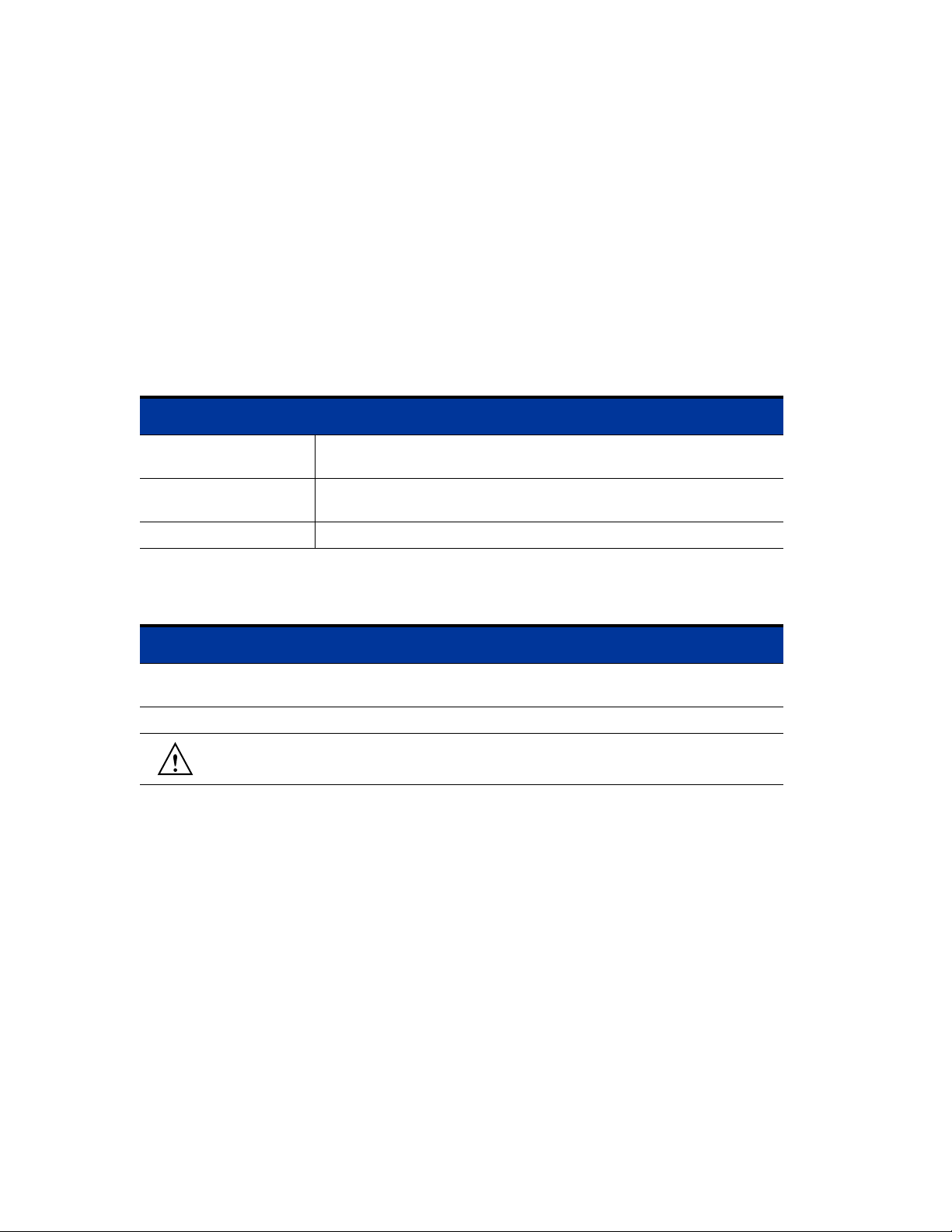
This section describes the hardware features of the Access Control Server 745wl, which is designed for
high-performance, high-density wiring-closet applications. Figure 2-1 shows an Access Control Server
745wl.
Figure 2-1. Access Control Server 745wl
The Access Control Server 745wl consists of a chassis, power supply, fans, I/O ports, indicators, and
switches. This unit has two RJ-45 connectors—one for the network uplink, used to connect the unit to the
network, and one that is used for the redundant Access Control Server.
2-1
Page 18
Hardware Installation
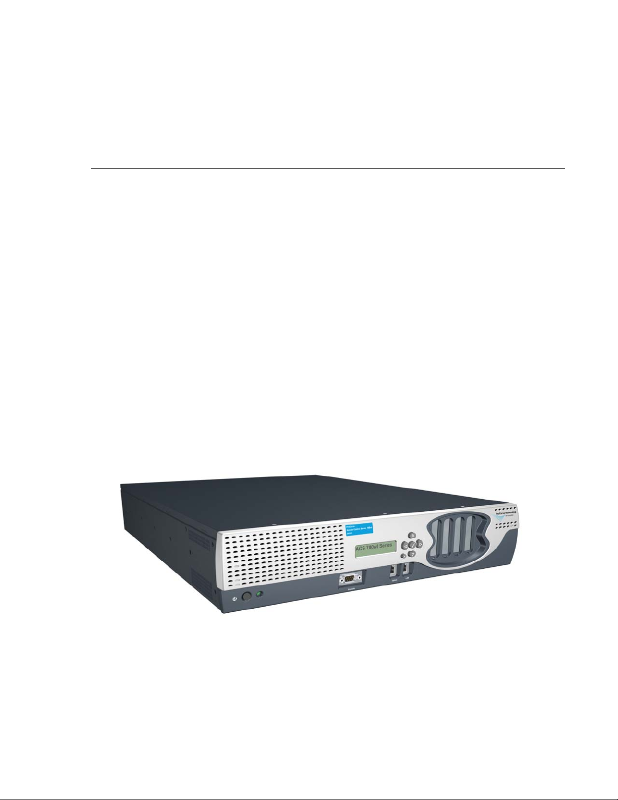
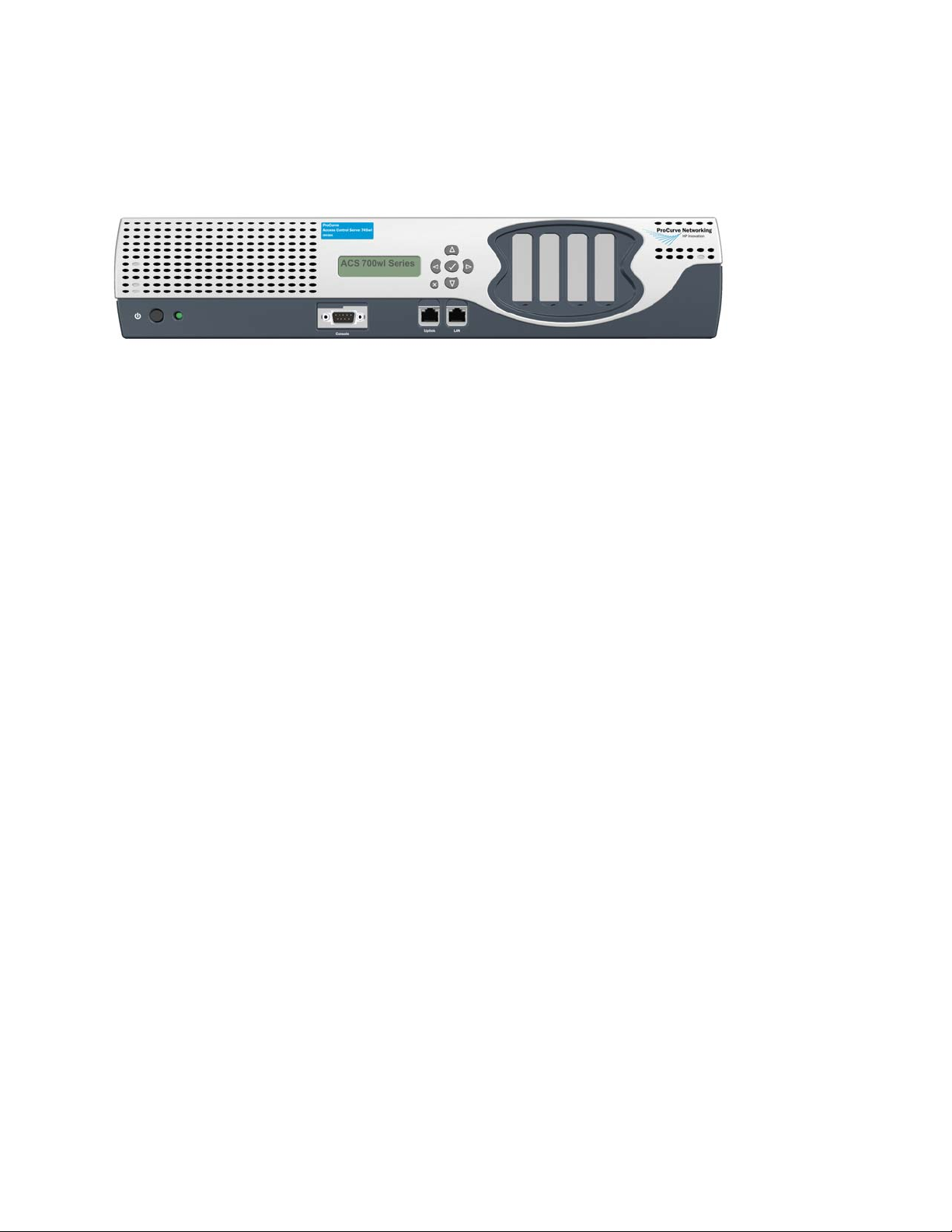
Figure 2-2 shows a front panel view of the Access Control Server 745wl.
Figure 2-2. Front panel view—Access Control Server 745wl
System Memory/Storage
The Access Control Server 745wl is equipped with a hard disk.
Chassis
The chassis is 17.00” (43.2 cm) wide, 22.00” (55.9 cm) deep, and 3.5” (8.9 cm) high, which is 2 rack units
(RU) high. It weighs approximately 35 lbs (15.9 kg). It can be rack-mounted using the front brackets
provided.
Power Supply
TheAccess Control Server 745wl contains an auto voltage sensing power supply. Input is 100-220 volts,
2.5A, 50/60 Hz, with a measured 350 watts output.
Fans
Note: For environmental specifications, see “Site Power Requirements and Heat Dissipation” on
page 2-5.
The system fan assembly provides cooling air for the internal chassis components. The fans exhaust warm
air from the back and draw in cool air at the front. The Access Control Server 745wl monitors its internal
fan speeds, internal chassis temperature, and power supply voltages. The status of these values are
reported by system software.
I/O Ports
Table 2-1 summarizes the functional I/O ports on the Access Control Server 745wl.
2-2 ProCurve Secure Access 700wl Series Installation and Getting Started Guide
Page 19
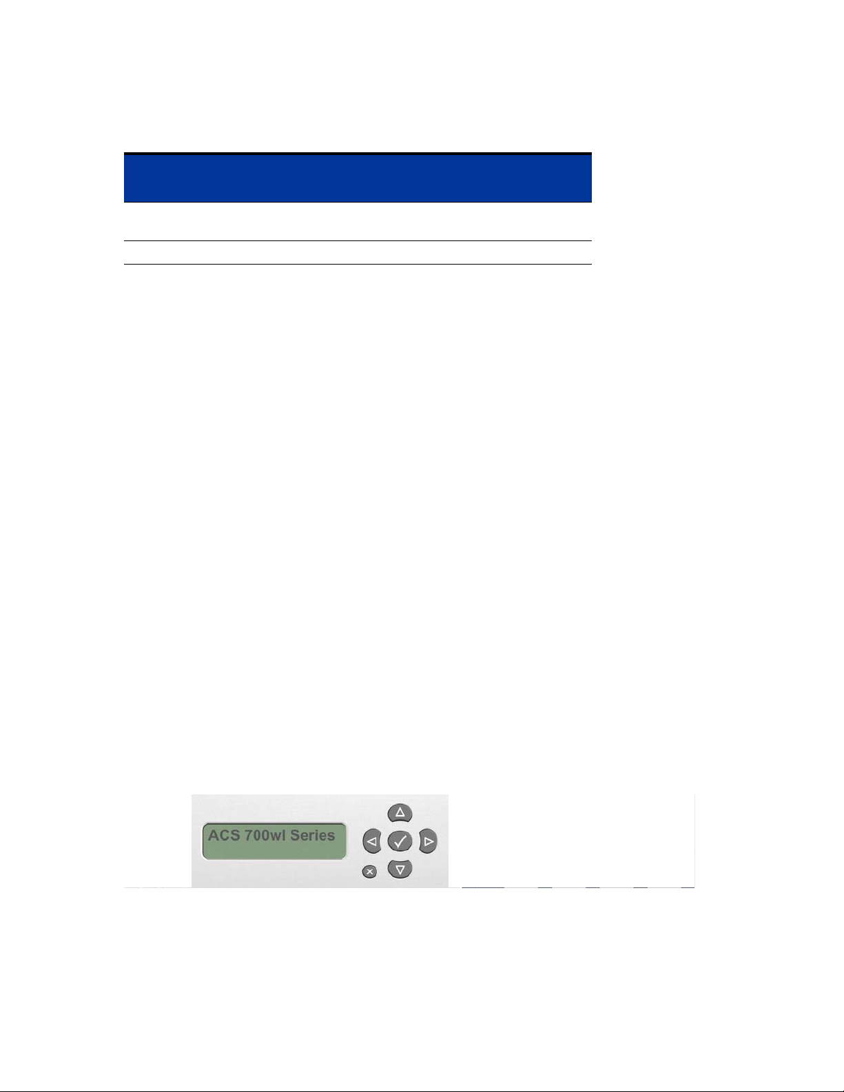
Table 2-1. I/O Ports
Port Function Description
Hardware Installation
Number
of Ports
Network Uplink RJ-45, 10Base-T/
100Base-TX/1000Base-T
Serial Console DB9, Serial Port 1
1
Controls and Indicators
Controls
There is only one control on the front of the chassis, a power button, labeled I/0. The power button is a
momentary switch and is used to turn on the system.
Note: The front panel power button should not be used to power off the system. Turning off the
system should be performed through software.
There is also a power supply switch on the rear of the Access Control Server 745wl, next to the power
cord socket. This switch must be left in the On (
used to power on the system. When this switch is in the Off (0) position, the front panel power button
will not function.
System Status Indicator
There is one system status LED indicator on the front of the chassis—Power (ON). ON is lit when the
power supply is plugged into a live outlet, the rear panel On/Off switch is in the On position, and the
power is turned on by the front panel On/Off button.
I) position for the unit to be operational, and cannot be
LCD Display
The LCD display can be used to view the system’s network parameters, and to power down the system.
The LCD display is located in the middle of the front panel of the Access Control Server 745wl. It is a 16character by two-line display, with six buttons located to the right of the display (Figure 2-3).
Figure 2-3. LCD Display
Appendix B, “LCD Display Description” describes the messages and operation of the LCD display panel.
ProCurve Secure Access 700wl Series Installation and Getting Started Guide 2-3
Page 20
Hardware Installation
Network Uplink Status Indicators
A detailed view of the network interface (uplink port) is shown in Figure 2-4.
Figure 2-4. Network Uplink port
LED1 LED2
The two LEDs, LED1 and LED2, provide information on the port speed and data connection state of the
default network uplink port as shown in Table 2-2.
Table 2-2. Network uplink LED status
LED State LED1 (Port Speed) LED2 (Connection)
On Green: 10 Mbps, 1000 Mbps Link 100 Mbps, 1000 Mbps Link
Off 100 Mbps Link and Activity 10 Mbps Link and Activity
Blinking Green (Blink): 10 Mbps, 1000 Mbps Activity 100 Mbps, 1000 Mbps Link
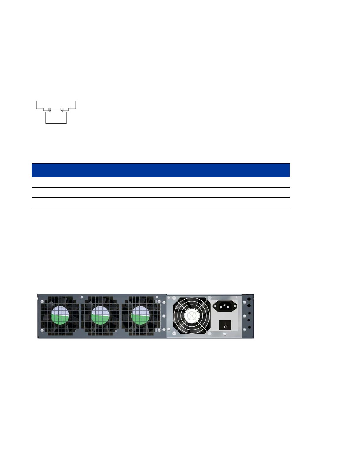
Rear Chassis
Figure 2-5 shows the rear of the Access Control Server 745wl. There is one control on the rear of the
chassis, a power switch. This switch cannot be used to power on the system. When this switch is in the
Off (0) position, the front panel power button will not function.
Note:
Figure 2-5. Rear chassis of an Access Control Server 745wl
The power switch must be left in the On (I) position for the unit to be operational.
Site Planning Checklist
Before installing an Access Control Server 745wl or XL Access Controller Module, you should evaluate
the items in the following site planning checklist:
Space Evaluation
•Space and layout
2-4 ProCurve Secure Access 700wl Series Installation and Getting Started Guide
Page 21

• Floor covering
• Impact and vibration
• Lighting
• Maintenance access
Environmental Evaluation
• Ambient temperature
•Humidity
• Altitude
• Atmospheric contamination
•Airflow
Power Evaluation
•Input power type
• Proximity of receptacle to equipment
Hardware Installation
• UPS for power failures
Grounding Evaluation
• Circuit breaker size
Cable and Interface Equipment Evaluation
•Cable type
• Connector type
• Cable distance limitations
• Interface equipment (transceivers)
EMI Evaluation
• Distance limitations for signaling
•Site wiring
• RFI levels
Site Power Requirements and Heat Dissipation
Table 2-3 shows the site power requirements and heat dissipation for the Access Control Server 745wl.
ProCurve Secure Access 700wl Series Installation and Getting Started Guide 2-5
Page 22

Hardware Installation
Table 2-3. Site Power Requirements, Temperature and Heat Dissipation Parameters
Parameter Value
AC Input Power (Watts) 170
Heat Dissipation (BTU/Hr.) 580
AC Input Current at 120 VAC (Amps) 1.4
AC Input Current at 240 VAC (Amps) .70
Operating Temperature Range, ×C 5 to +50
Storage Temperature Range, ×C -40 to +65
Humidity Range, non-condensing, percent 5 to 90
°
C
°
C
Installing a 700wl Series System
Unpacking
Carefully unpack the contents of the shipping containers, and save the containers and all packing
materials. To save storage space, you may want to flatten the containers. Check that the following is
included:
•Chassis
• Hardware and Accessories Kit
— 12-24 x 5/8 inch Phillips pan-head bolts, zinc (quantity: 4)
— 10-32 x 5/8 Phillips washer-head bolts, black (quantity: 4)
— Mounting Slide Kit
—U.S. power cord
— AT null modem cable (DB-9 female/DB-9 female)
• Documentation Kit
— Documentation CD-ROM
— Software License Agreement
— Software Release Notes
— ProCurve Secure Access 700wl Series Installation and Getting Started Guide (this document)
If any of the above are missing, contact HP immediately and do not attempt installation.
Rack Mounting the Chassis
Each Access Control Server 745wl comes with a steel mounting kit suitable for mounting the chassis in a
standard 19-inch (48.3 cm) equipment rack. Rack mounting instructions are included in the kit.
2-6 ProCurve Secure Access 700wl Series Installation and Getting Started Guide
Page 23

Hardware Installation
Due to the weight of the unit, we highly recommend using these rails to mount the unit. This unit is not
suitable for mounting in racks with obstructions (such as a power strip) that could impair access to the
device. The air space in the front and rear of system should be 6.00 inches minimum.
Caution: Ground the chassis properly with the supplied power cord.
Caution: Be sure to position the power cord so that you can easily disconnect the chassis.
Caution: Do not install the chassis in an environment where the operating temperature might exceed
°
10
C (104°F).
Caution: Do not restrict air flow around the side and rear of the chassis. The air space in front and rear
of system should be 6.00 inches minimum.
Connecting Power to the Chassis
Follow these steps to connect power to the chassis:
Step 1. Before you connect the power supply to a power source, ensure that all site power and grounding
requirements listed in “Site Power Requirements, Temperature and Heat Dissipation
Parameters” on page 2-6 have been met.
Step 2. Plug the power cord into the rear of the chassis.
Step 3. Connect the other end of the power cord to an AC-power input source.
Caution: Ground the chassis properly with the supplied power cord.
Step 4. Be sure to position the power cord so that you can easily disconnect it from the chassis.
ProCurve Secure Access 700wl Series Installation and Getting Started Guide 2-7
Page 24

Page 25

NETWORK SETUP
This chapter describes the network setup of your 700wl Series system on an existing network to allow
interoperability and proper network security for all equipment.
It consists of the following sections:
Getting Started . . . . . . . . . . . . . . . . . . . . . . . . . . . . . . . . . . . . . . . . . . . . . . . . . . . . . . . . . . . . . . 3-1
Access Control Server Setup . . . . . . . . . . . . . . . . . . . . . . . . . . . . . . . . . . . . . . . . . . . . . . . . . . 3-2
Access Controller Module Setup . . . . . . . . . . . . . . . . . . . . . . . . . . . . . . . . . . . . . . . . . . . . . 3-14
3
Getting Started
The network configuration procedures in this chapter are performed after the hardware has been
installed. Access Control Server installation is described in Chapter 2, “Hardware Installation”, and
Access Controller Module installation is described in the ProCurve Series 5300xl Switches Installation and
Getting Started Guide. These network configuration procedures make a 700wl Series system (an Access
Control Server and associated Access Controller Modules) usable on your network.
The Access Control Server must always be installed before any Access Controller Modules are installed.
700wl Series system components are configured and managed centrally from the Administrative Console
that runs on the primary Access Control Server. Therefore, the initial network configuration includes only
the steps necessary to make the component accessible from the Access Control Server Administrative
Console.
• For an Access Control Server, you may be able to access the Administrative Console immediately upon
connecting the unit to your network, as the unit is configured by default to request an IP address using
the Dynamic Host Configuration Protocol (DHCP). If a DHCP server is reachable, and an address is
assigned to the ProCurve unit, you can point your browser to that IP address and access the
Administrative Console. You can determine the IP address by looking at the LCD panel on the front of
the unit.
If you want to assign a static IP address to the unit, you can connect a serial console to the unit’s
serial console port, and assign an IP address prior to connecting the unit to the network. Once you
have provided the necessary addressing information, you can connect to the Administrative
Console using a browser and complete the configuration.
• Management and configuration of an Access Controller Module is also performed from the centralized
Administrative Console on the Access Control Server. However, for the Access Control Server and the
Access Controller Module to communicate, the Access Controller Module must first be configured with
the IP address of the Access Control Server, and the shared secret used to validate the Access Controller
Module to its Access Control Server. Initial configuration is provided in the ProCurve Series 5300xl
Switches Installation and Getting Started Guide.
3-1
Page 26

Network Setup
Access Control Server Setup
You can perform the initial network configuration of an Access Control Server in one of three ways:
• Connect a serial console to the Access Control Server’s serial console port and use the Command Line
Interface (CLI). See “Initial Configuration Using the CLI” on page 3-3 for detailed instructions.
• Connect the Access Control Server to your network, allowing it to get an IP address using the Dynamic
Host Configuration Protocol (DHCP). Then connect to its Administrative Console with a web browser.
See “Initial Configuration Using the Administrative Console” on page 3-8 for detailed instructions.
• Connect the Access Control Server to your network, allowing it to get an IP address using the
Dynamic Host Configuration Protocol (DHCP). Then open an SSH connection and log into the CLI.
The 700wl Series system supports SecureCRT 3.3 with the Auto Detect or Standard SSH server
options. See “Connecting Using SSH” on page 3-6 for detailed instructions.
Configuration beyond basic network installation, specifically the process of customizing the function of a
ProCurve 700wl Series system to a particular end-user environment, is not described in this manual.
Configuration performed after initial network installation is described in the ProCurve Secure Access 700wl
Series Management and Configuration Guide.
IP Addressing Considerations
An Access Control Server requires a stable IP address, so the Access Controller Modules under its control
can readily identify and communicate with the server. You can either arrange for DHCP to always assign
the same IP address to the Access Control Server, or you can manually enter a static IP address. Most
commonly, a static IP address is used.
A 700wl Series system ships configured by default to obtain its IP address and other information from a
Dynamic Host Configuration Protocol (DHCP) server. This means the system will attempt to obtain an IP
address as soon as it is connected to the network and is powered up.
Note: If you do not want the Access Control Server to attempt to use DHCP, you must configure its IP
address before you connect it to the network for the first time. You can configure the Access Control
Server without connecting it to the network using a serial console connected to the serial port.
If you elect to obtain the Access Control Server IP address using DHCP, the Access Control Server can
also obtain the hostname, domain name, subnet mask, and the IP addresses of the gateway, DNS servers,
WINS server, and NTP server from the DHCP server. The information it receives depends on how you
configured your DHCP server.
If you configure your DHCP server to assign the same IP address to the Access Control Server every time,
then even after a factory reset (which clears all configuration changes and returns the system to its default
settings) the Access Control Server will obtain the correct IP address upon a reboot. If you elect to use a
static IP address, you will need to reconfigure the address after a factory reset.
3-2 ProCurve Secure Access 700wl Series Installation and Getting Started Guide
Page 27

Network Setup
To install an Access Control Server onto a network, you need the information shown in Table 3-1:
Table 3-1. Installation Parameters
Parameter Description
Access Control Server hostname
(optional)
Domain name (optional) Defines the Access Control Server’s domain if a
IP address This can be assigned as a static IP address or can be
Subnet mask (Netmask) Defines the Access Control Server’s subnet range. Can
Gateway (default router) IP address Defines the default router. Can be obtained via DHCP.
Primary and secondary DNS server IP
addresses
Access Control Server shared secret Secret key used to establish trust relationship with an
Must be fully-qualified if provided. Example:
am21b.corp.com
hostname is not provided. Example: corp.com
obtained via DHCP (the default).
be obtained via DHCP. Example: 255.255.255.0.
Defines the location of the primary and backup DNS
servers. Can be obtained via DHCP.
Access Controller Module. Alphanumeric string. The
same shared secret must be configured on the Access
Controller Module.
Initial Configuration Using the CLI
Note: If you want your system to receive its IP address via DHCP, and you do not plan to reconfigure
the uplink port, you can simply connect the unit to your network. By default a new unit requests an
address via DHCP. You can then follow the instructions in the section “Initial Configuration Using the
Administrative Console” on page 3-8.
The remainder of this section assumes you plan to assign a static IP address to the unit.
You can connect a serial console to the Access Control Server’s serial console port, and then configure the
Access Control Server’s network settings using the CLI.
You can use the CLI to perform both basic and advanced network configuration on an Access Control
Server. However, it is recommended that management and configuration normally be done through the
browser-based Administrative Console. Therefore, this section includes configuration of only those
parameters necessary to allow the Access Control Server to be recognized and communicate on the
network.
Note: See Appendix A in the ProCurve Secure Access 700wl Series Management and Configuration
Guide for full documentation of the commands available from the CLI.
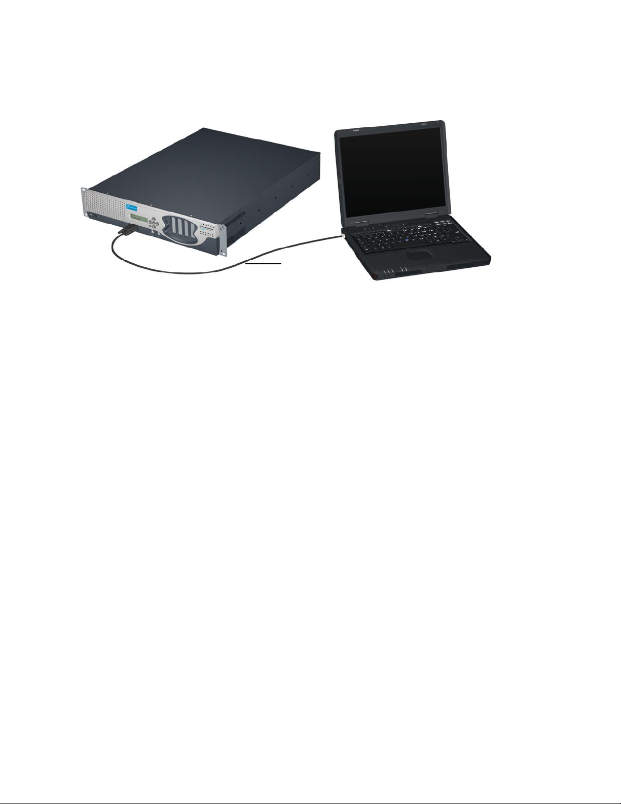
Connecting a Serial Console
To use the CLI, you must first connect a null modem serial cable from the serial port male DB-9 connector
on the Access Control Server to a serial console. (Figure 3-1).
ProCurve Secure Access 700wl Series Installation and Getting Started Guide 3-3
Page 28
Network Setup
Figure 3-1. Connecting an Access Control Server to a Serial Console
External
Management
System
Serial Cable
Access Control Server 745wl
Use a craft terminal or a computer with a terminal emulation application to access the CLI. You will need
a serial cable with DB-9 female connectors on both ends to connect to the Access Control Server. A serial
crossover cable with DB-9 female connectors is included in the accessory kit shipped with the unit. See
Appendix D, “Cable and Connector Specifications” for the pinout specifications for this connector.
Configure the terminal session on your management computer as follows:
• Baud rate: 9600
• Data Bits: 8
• Stop bits: 1
• Flow Control: None
•Parity: None
Issuing Network Setup Commands from the Serial Console
After you have connected the serial console, follow these steps to configure the Access Control Server
network parameters. These instructions assume you have not connected the unit to the network.
Step 1. Power up the Access Control Server. You will see a series of messages on the terminal emulator
as the system boots and initializes itself.
At the end of the boot and initialization sequence you will see a prompt:
Serial Console
login:
Step 2. At the login prompt, enter admin as the login and then enter admin as the password.
login:admin
Password: xxxxx
The system then displays the command prompt:
HP ProCurve Access Control Server 700wl Series #<MAC address>
HP 700wl Series@[0.0.0.0]:
Step 3.
To configure the system with a static IP address, enter the following commands:
3-4 ProCurve Secure Access 700wl Series Installation and Getting Started Guide
Page 29
Network Setup
set ip <ip address> <netmask>
<ip address>
is the IP address you want to assign to the Access Control Server. Make sure
you assign an IP address that is valid for use as a device address. For example, IP addresses
ending in .0 (xxx.xxx.xxx.0) are normally used as broadcast addresses and should not be
used as a device address.
<netmask> is the subnet mask that defines the subnet address range for the Access Control
Server. It must be entered in the format xxx.xxx.xxx.xxx — for example, 255.255.255.0.
set hostname <fully qualified hostname>
The hostname must be a valid, fully qualified name that correctly resolves to the IP address
you assign to this Access Control Server. This parameter is optional.
set gateway <ip address>
<ip address>
set dns <primary dns ip address> <secondary dns ip address>
is the address of the default router.
The two DNS IP addresses are the addresses of your primary and secondary DNS servers.
The secondary IP address is optional.
Step 4. Change the administrator login and password by entering the following command:
set admin <login-name> <password> <password>
You must enter the password twice.
The built-in administrator logon cannot be deleted.
Step 5. Set the shared secret the Access Controller Modules will use to validate themselves to the Access
Control Server as follows:
set sharedsecret <secret> <secret>
You must enter the shared secret twice.
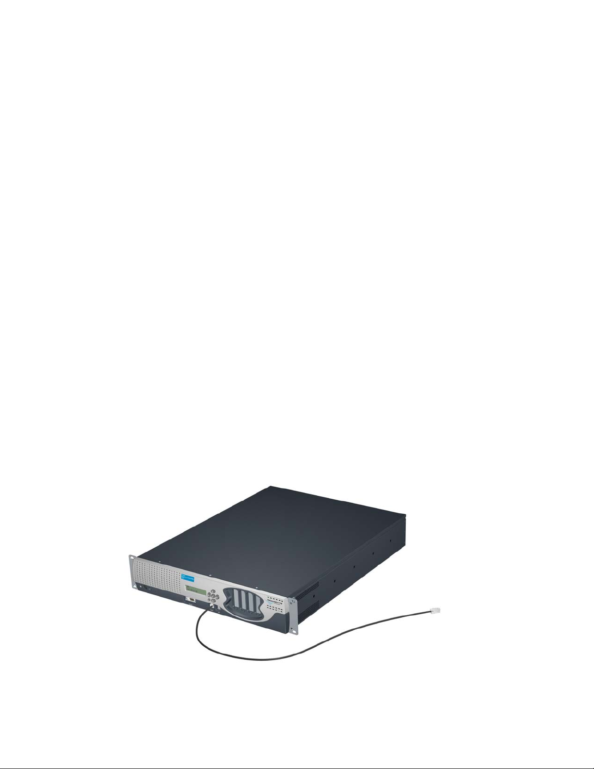
Step 6. Connect the Access Control Server Network Uplink port to your network (Figure 3-2).
Figure 3-2. Connecting the Access Control Server to the Network
Access Control Server
To Network
Default
Network Uplink
Port
ProCurve Secure Access 700wl Series Installation and Getting Started Guide 3-5
Standard Ethernet Cable
Page 30
Network Setup
Step 7.
Verify that you can access the Administrative Console from a browser running on a computer
system connected to your network by entering the IP address of the unit:
http://<ip address>
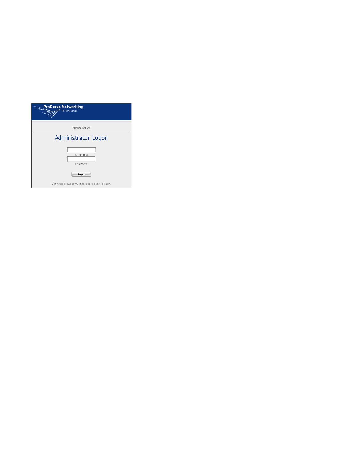
The Administrator Logon page should appear (see Figure 3-3).
Figure 3-3. Administrator Logon
Step 8.
Step 9. You can now use the browser-based Administrative Console to complete the configuration of
Log on using the username and password you set in Step 4.
other settings such as advanced network features, session logging, SNMP management, the
HTTP proxy feature, Wireless Data Privacy settings, and setting up authentication and access
policies for client network access. For example, see Step 18 on page 3-13 in the section“Initial
Configuration Using the Administrative Console” for information on setting the system date,
time and time zone.
See the ProCurve Secure Access 700wl Series Management and Configuration Guide for detailed
information on the features of the Administrative Console.
Connecting Using SSH
To use SSH to access the CLI, you must first connect an Ethernet cable from the uplink port on the
Access Control Server to the network. (Figure 3-2). The 700wl Series system supports SecureCRT 4.05
with the Auto Detect or Standard SSH server options.
Issuing Network Setup Commands Using SSH
After you have connected the Access Control Server to the network, follow these steps to configure the
Access Control Server network shared secret. These instructions assume you have used DHCP to obtain
the IP address and other network parameters depending on how you have configured your DHCP
server. The Access Control Server ships configured by default to obtain its IP address and other
information from a DHCP server.
Step 1. Power up the Access Control Server. After the Access Control Server has completed its
initialization, start an SSH tunnel using the IP address displayed in the LCD panel and admin as
the login.
Step 2. You will be prompted to enter the password, enter admin as the initial password.
3-6 ProCurve Secure Access 700wl Series Installation and Getting Started Guide
Page 31
Network Setup
Password: xxxxx
The system then displays the command prompt:
HP ProCurve Access Control Server 700wl Series #<MAC address>
HP 700wl Series@[0.0.0.0]:
Note: The IP address of the Access Control Server will be reflected in the prompt instead of the
0.0.0.0 address.
Step 3.
Change the administrator login and password by entering the following command:
set admin <login-name> <password> <password>
You must enter the password twice. The built-in administrator logon cannot be deleted.
Step 4. Set the shared secret the Access Controller Modules will use to validate themselves to the
Access Control Server as follows:
set sharedsecret <secret> <secret>
You must enter the shared secret twice.
Step 5. Verify that you can access the Administrative Console from a browser program running on a
computer connected to your network by entering the IP address of the unit:
http://<ip address>
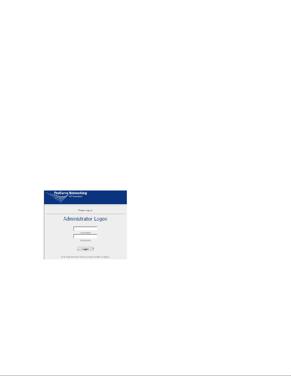
The Administrator Logon page should appear (see Figure 3-4).
Figure 3-4. Administrator Logon
Step 6. Log on using the username and password you set in Step 3.
Step 7. You can now use the browser-based Administrative Console to complete the configuration of
other settings such as advanced network features, session logging, SNMP management, the
HTTP proxy feature, Wireless Data Privacy settings, and setting up authentication and access
policies for client network access.
For example, see Step 18 on page 3-13 in the section “Initial Configuration Using the
Administrative Console” for information on setting the system date, time and time zone.
See the ProCurve Secure Access 700wl Series Management and Configuration Guide for detailed
information on the features of the Administrative Console.
ProCurve Secure Access 700wl Series Installation and Getting Started Guide 3-7
Page 32

Network Setup
Initial Configuration Using the Administrative Console
If you want to perform network installation of your Access Control Server using the browser-based
Administrative Console, you must connect to the Access Control Server over the network. This requires
that you know the IP address (or valid hostname) of your Access Control Server. Since the Access Control
Server by default requests an IP address from a DHCP server, you can use the IP address assigned by the
DHCP server to connect to the Administrative Console.
Before you connect your Access Control Server to the network, you can configure the DHCP server to
provide a fixed IP address to the Access Control Server. The DHCP server can also provide the netmask,
default gateway (router) IP address, and primary and secondary DNS IP addresses. You will only need to
change the administrator user ID and password (strongly recommended) and configure the shared secret
that enables Access Controller Modules to communicate with the Access Control Server.
If you cannot or do not wish to configure your DHCP server to provide a known address, then in order to
connect to the Access Control Server you must determine the IP address supplied by DHCP. The easiest
way to do this is by looking at the LCD display on the Access Control Server. The LCD alternates the
display of the IP address with the display of the date/time and software version number.
If you do not have access to the Access Control Server itself, you can find the IP address by examining the
logs on your DHCP server to determine which address was given to the Access Control Server. An
alternate method is to connect a serial console as described in “Initial Configuration Using the CLI”, and
note the IP address that is contained as part of the CLI prompt.
To perform the initial configuration using the Administrative Console, do the following:
Step 1. Connect the Access Control Server Network Uplink port to your network (Figure 3-2).
Step 2. Point a web browser to the Access Control Server by entering a URL of the form:
http://<ip address>
where <ip address> is the address assigned to the Access Control Server, or
http://<fully-qualified hostname>
if your DNS server is set to resolve the hostname to the IP address provided by your DHCP
server.
The Administrator Logon page appears (Figure 3-5).
Figure 3-5. Administrator Logon
3-8 ProCurve Secure Access 700wl Series Installation and Getting Started Guide
Page 33

Network Setup
Step 3.
For both the username and password, enter admin, and click Logon. The initial Administrative
Console page appears, as shown in Figure 3-6.
The Access Control Server will be displayed in the left panel of the page.
Figure 3-6. Initial Administrative Console Page (Equipment Status)
Access Controller Modules appear here.
Step 4.
Access Control Server appears here.
Click the NETWORK button. The System Components page appears, as shown in Figure 3-7.
ProCurve Secure Access 700wl Series Installation and Getting Started Guide 3-9
Page 34

Network Setup
Figure 3-7. System Components Page
Step 5.
Click the Local Networks tab below the navigation bar. This brings up the Local Networks page
(see Figure 3-8).
3-10 ProCurve Secure Access 700wl Series Installation and Getting Started Guide
Page 35

Figure 3-8. Local Networks Page
Network Setup
Step 6.
Step 7. Enter the name of the domain in which this Access Control Server resides.
Step 8. To use DHCP to obtain an IP address for this unit, select Using DHCP from the Configure drop-
If appropriate, enter a fully-qualified hostname for this Access Control Server.
down list.
When
Configure is set to Using DHCP, you cannot change the IP Address, Subnet Mask, or
Gateway. You can change the DNS and WINS server IP addresses, if necessary.
If your DHCP server is configured appropriately, the IP address, subnet mask (netmask),
gateway, and primary and secondary DNS addresses will already be filled in.
Step 9. To set a static IP address, select Manually from the Configure drop-down list, then type the IP
Address and other values, as appropriate, in the fields on this page.
Step 10. Click Save.
ProCurve Secure Access 700wl Series Installation and Getting Started Guide 3-11
Page 36

Network Setup
Step 11.
Return to the System Component page (Figure 3-7), and in the Component Name column, click the
IP address link for the Access Control Server.
The Edit Access Control Server page appears (Figure 3-9).
Figure 3-9. Edit Access Control Server Page
Step 12.
To give the Access Control Server a descriptive name, replace the IP address in the Name field
with the name you want to use.
Step 13. In the Shared Secret field, type the shared secret that Access Controller Modules will use to
validate themselves to this Access Control Server.
Step 14. Retype the shared secret in the Confirm Shared Secret field.
Step 15. Change the administrator username and password by typing a new username and password, and
confirming the new password in the appropriate fields.
3-12 ProCurve Secure Access 700wl Series Installation and Getting Started Guide
Page 37

Network Setup
Step 16.
If you want to allow remote access to the CLI on this unit via a remote SSH client, leave the check
in the
Enable SSH command line interface box (this is the default). To disable remote access,
uncheck the box.
Enable technical support access only if requested to do so by an authorized ProCurve support
engineer.
Step 17. Click Save.
Note: You must enter and confirm a shared secret—the 700wl Series system does not let you
save this configuration without one.
Step 18. To set the system date and time, and time zone if necessary, click the Date & Time tab. The Date &
Time page appears (see Figure 3-10).
Figure 3-10. Date & Time Page
Step 19.
Step 20. To configure an NTP server, click the Set time using network time server check box, and type the
To set the time zone, select the appropriate setting from the Time Zone drop-down list.
IP address of a primary and (optionally) a secondary NTP server.
Step 21. Click Save.
Step 22. To set the date and time immediately, select the appropriate values and click Set Time Now.
ProCurve Secure Access 700wl Series Installation and Getting Started Guide 3-13
Page 38

Network Setup
Note: You cannot set the time zone or NTP server in the same operation as manually setting
the time.
Note: If you are using NTP to get the date and time, the underlying GMT/UTC time difference
between the Access Control Server and its associated Access Controller Modules should be
less than 900 seconds for the clocks to be synchronized. A variance in (GMT/UTC) time
between the Access Control Server and the Access Controller Module clocks greater than 900
seconds generally cannot be synchronized by NTP without rebooting the Access Controller
Module. Having Access Controller Module and Access Control Server clocks start off with a
high initial variance is not recommended.
There may be a delay of several minutes before all 700wl Series system units are initially
synchronized.
This completes the basic configuration of an Access Control Server. You can now configure Access
Controller Modules to communicate with this Access Control Server using the IP address and shared
secret set in the previous steps.
To complete the configuration of the 700wl Series system, you will need to configure other settings such
as advanced network features, session logging, SNMP management, the HTTP proxy feature, wireless
data privacy settings, and set up authentication and access policies for client network access.
See the ProCurve Secure Access 700wl Series Management and Configuration Guide for detailed information on
the features of the Administrative Console.
Access Controller Module Setup
Configuration of an Access Controller Module is done primarily through the Administrative Console
running on the Access Control Server. However, in order for an Access Controller Module to be
recognized by the Access Control Server, the Access Controller Module must be configured with the
Access Control Server’s IP address and shared secret. Until this is done, the Access Control Server and
Access Controller Module will not be able to communicate. Therefore, the initial configuration must be
done through the CLI, as explained in the ProCurve Series 5300xl Switches Installation and Getting Started
Guide. Because an Access Controller Module does not provide its own browser-based Administrative
Console, it is managed through the Access Control Server.
IP Addressing Considerations
An Access Controller Module requires a stable IP address so that the Access Control Server can readily
identify and communicate with it. Set up a static IP address for an Access Controller Module using the
CLI, as explained in the ProCurve Series 5300xl Switches Installation and Getting Started Guide. A static IP
address must be reconfigured after a factory reset.
To install an Access Controller Module onto a network, you need the information shown in Table 3-2.
3-14 ProCurve Secure Access 700wl Series Installation and Getting Started Guide
Page 39

Table 3-2. Installation Parameters
Parameter Description
Access Controller Module IP address This is assigned as a static IP address.
Subnet mask (Netmask) Defines the Access Control Server’s subnet range. Can
be obtained via DHCP. Example: 255.255.255.0.
Gateway (default router) IP address Defines the default router. Can be obtained via DHCP.
Primary and secondary DNS server IP
addresses
Access Control Server IP Address The IP address of the Access Control Server that will
Access Control Server shared secret Secret key used to establish trust relationship between
Defines the location of the primary and backup DNS
servers. Can be obtained via DHCP.
manage this Access Controller Module. In an
environment with redundant Access Control Servers, this
must be the IP address of the Primary Access Control
Server.
the Access Control Server and an Access Controller
Module. Alphanumeric string. This must match exactly
the shared secret configured on the Access Control
Server.
Network Setup
Initial Configuration Using the CLI
Because an Access Controller Module does not provide its own browser-based Administrative Console,
the initial system configuration must be done using the CLI, as explained in the ProCurve Series 5300xl
Switches Installation and Getting Started Guide.
Note: See Appendix A in the “ProCurve Secure Access 700wl Series Management and Configuration
Guide” for a complete list of CLI commands.
Completing the Installation
You can complete the configuration of your Access Controller Module through the Administrative
Console.
Note: Beyond the basic setup, all Access Controller Module configuration must be done through the
Access Control Server Administrative Console.
Once the Access Controller Module is initially configured using the CLI, the Access Controller Module
should initiate communication with the Access Control Server. Once this has occurred, the Access
Controller Module should appear as a system component in the Access Control Server’s Administrative
Console.
Note: You can access online Help from within the Administrative Console at any time by clicking the
HELP button. This displays a separate window containing Help about the page you are viewing.
Step 1. Point your browser to the IP address of the Access Control Server, and log on to the
Administrative Console.
ProCurve Secure Access 700wl Series Installation and Getting Started Guide 3-15
Page 40

Network Setup
Step 2.
When the initial Administrative Console page appears (the Equipment Status page shown in
Figure 3-11), verify that this Access Controller Module appears in the list of Access Controller
Modules.
Figure 3-11. Initial Administrative Console Page (Equipment Status)
Access Controller Modules appear here.
Step 3.
You can now use the Administrative Console to complete the Access Controller Module
configuration, such as setting the system time and date, and configuring other necessary settings:
a. Click the NETWORK button. The System Components page appears, as shown in Figure 3-12.
3-16 ProCurve Secure Access 700wl Series Installation and Getting Started Guide
Page 41

Figure 3-12. System Components Page
Network Setup
Click the Local Networks tab below the Navigation bar. This brings up the Local Networks
b.
page (see Figure 3-13).
ProCurve Secure Access 700wl Series Installation and Getting Started Guide 3-17
Page 42

Network Setup
Figure 3-13. Local Networks Page
c.
From the System Components List in the left panel under the Local Networks heading, select
the Access Controller Module you just installed. The
d. Verify that the information for the Access Controller Module is correct, or enter additional
settings as necessary. From the
Advanced Setup sub-tab you can configure Bridging, IP
broadcast forwarding, and client polling; from the
Basic Setup page is displayed.
SSL sub-tab you can configure the address
of a proxy server for HTTP requests.
e. Click Save to save any changes you have made to any of the sub-tabs on this page.
Step 4. Complete the installation by connecting one or more wireless access points to the Access
Controller Module ports on the 5300xl switch, using standard (either crossover or straightthrough) 10Base-T/100Base-TX Ethernet cables.
See the ProCurve Secure Access 700wl Series Management and Configuration Guide for detailed information on
the features of the Administrative Console.
3-18 ProCurve Secure Access 700wl Series Installation and Getting Started Guide
Page 43

Network Setup
See the next chapter, “Basic Configuration” for instructions on configuring your 700wl Series system with
a demonstration user account, setting up wireless data privacy using PPTP, and allowing a user to
connect to the system as the demonstration user.
ProCurve Secure Access 700wl Series Installation and Getting Started Guide 3-19
Page 44

Page 45

BASIC CONFIGURATION
This chapter will help you accomplish the following:
• Create a demonstration user account that can log on and be authenticated through the 700wl Series
system built-in user database
• Configure the 700wl Series system as a VPN gateway using PPTP encryption
• Configure a Windows client system to establish a network connection using the PPTP protocol
• Connect to the 700wl Series system as a client using the PPTP protocol, and authenticate the
demonstration user against the built-in database
• (Optional) Configure the 700wl Series system to use a RADIUS server for user authentication, and log
on a user that can be authenticated by the RADIUS server.
This chapter includes the following sections:
Procedure Overview . . . . . . . . . . . . . . . . . . . . . . . . . . . . . . . . . . . . . . . . . . . . . . . . . . . . . . . . . 4-1
Preparation . . . . . . . . . . . . . . . . . . . . . . . . . . . . . . . . . . . . . . . . . . . . . . . . . . . . . . . . . . . . . . . . . 4-2
Creating a User Account in the Built-In Database . . . . . . . . . . . . . . . . . . . . . . . . . . . . . . . . 4-2
4
User Authentication Through the Default Logon Page . . . . . . . . . . . . . . . . . . . . . . . . . . . 4-3
PPTP Gateway Configuration . . . . . . . . . . . . . . . . . . . . . . . . . . . . . . . . . . . . . . . . . . . . . . . . . 4-4
Configuring Access Policies for Encryption . . . . . . . . . . . . . . . . . . . . . . . . . . . . . . . . . . . . . 4-5
PPTP Client Configuration . . . . . . . . . . . . . . . . . . . . . . . . . . . . . . . . . . . . . . . . . . . . . . . . . . . 4-8
User Authentication Via PPTP Connection . . . . . . . . . . . . . . . . . . . . . . . . . . . . . . . . . . . . . 4-11
External Authentication Service Configuration . . . . . . . . . . . . . . . . . . . . . . . . . . . . . . . . . 4-11
Verify the External Authentication Service . . . . . . . . . . . . . . . . . . . . . . . . . . . . . . . . . . . . . 4-15
Procedure Overview
This chapter assumes that you have installed an Access Control Server and an Access Controller Module
and have performed the basic configuration following the instructions in the previous chapters. It
assumes you have verified that the Access Controller Module appears in the Access Control Server’s
Administrative Console.
To accomplish the objectives of this chapter, the instructions lead you through the following steps:
Step 1. Create a demonstration user account (username and password) in the Rights Manager's built-in
database.
4-1
Page 46

Basic Configuration
Step 2.
Step 3. Log the user on using the default browser-based logon page.
Step 4. Configure the 700wl Series system to act as a VPN gateway using PPTP encryption.
Step 5. Configure the Windows client to establish a PPTP connection with the 700wl Series system.
Step 6. Connect the client to the 700wl Series system using the PPTP connection process.
Step 7. (Optional) Configure the 700wl Series system to use a RADIUS server for user authentication.
Step 8. (Optional) Verify that the RADIUS Authentication Service is set up correctly using the Trace
Step 9. (Optional) Log on using a user account known to the RADIUS authentication server, and verify
The following procedures can be performed using an Access Control Server.
Directly connect a Windows client to the 700wl Series system through an Access Controller
Module downlink port.
The user should have full IP access to the network. This shows that the user can successfully
connect to the system and gain network access.
The user should have full IP access to the network. Again, this shows that the client can connect
to the system and gain access to the network.
Transaction
network access.
feature.
Preparation
Before you begin the system configuration process, review the following list to make sure you have the
required components available and configured as specified:
• A management workstation running the Windows IE 6 or Netscape 7.1 browser, to be used to perform
configuration tasks on the 700wl Series system.
• One Windows-based PC or Laptop preset to obtain an IP address automatically (via DHCP). This
system will be used to function as a client once the configuration is complete.
• One standard Ethernet cable to connect the PC/laptop to an Access Controller Module downlink port.
• (Optional) One RADIUS server. You must configure the RADIUS server to accept authentication
requests from the Access Control Server, which acts as a RADIUS client. A user account must be created
in the RADIUS database. Please consult the ProCurve Secure Access 700wl Series Management and
Configuration Guide for more information on other supported external authentication servers.
Note: If you want to use the same PC or laptop as both the management station and a demonstration
client, you will need to alternately connect it either to the network (for use as a management station) or
to an Access Controller Module downlink port (for use as a client). You will also need to force a renewal
of your IP configuration each time you move from one connection to the other.
Creating a User Account in the Built-In Database
In order for a user to log in, the 700wl Series system must be able to authenticate the user through some
authentication service. The simplest form of authentication service is the built-in database included in the
700wl Series system Rights Manager. In this step, you add a user to the built-in database so you can log
on to your network as that user through the 700wl Series system.
4-2 ProCurve Secure Access 700wl Series Installation and Getting Started Guide
Page 47

Basic Configuration
Step 1.
Point your browser to the IP address or hostname of your Access Control Server, and log on to
the Administrative Console.
Step 2. From the initial page, click the RIGHTS button to go to the Rights Manager.
The Rights Setup page appears.
Step 3. Click the Identity Profiles tab below the Navigation bar.
The Identity Profiles page appears, showing a list of the currently-defined Identity Profiles.
Step 4. Click the Users link in the left panel of the page.
The Users page appears, with an empty Users list.
Step 5. Click the New User button.
The New User page appears.
Step 6. Enter the following information:
•
Name: A descriptive name, such as Demonstration User. This is not the logon name.
•
Username/MAC Address: Demo (or a different user name). This is the logon name.
Do not check the MAC Address User check box.
•
Password: password (or any password you like)
Confirm Password: must be the same as that entered into the first password field.
Step 7. Click Save.
User Authentication Through the Default Logon Page
In this step, you connect your Windows PC to an Access Controller Module downlink port and log onto
your network using the username and password you added to the built-in database. If this is successful,
you should be able to access the Internet and other resources on your network as normal.
Note: If you are using the same Windows PC as a client that you have been using for configuration,
and the PC’s network interface is configured to use a static IP address, you must change its properties
so that it will obtain an IP address automatically using DHCP.
Step 1. Plug the Ethernet cable from your PC into one of the Access Controller downlink ports.
If you are using the same PC as both a client and a management station, you must release the
existing IP configuration (in Windows) from the network interface of the PC as follows:
From the Windows Start menu, click Run then enter the command:
ipconfig /release
Step 2.
Step 3. Start your web browser and go to any web site. After a moment the web browser will display the
Power on the PC to obtain a new IP configuration from DHCP through the Access Controller, or
do the following:
From the Start menu, click Run, then enter the command:
ipconfig /renew
The PC should receive an IP address in the 42.x.x.x range.
ProCurve 700wl Series Logon page (Figure 4-1).
ProCurve Secure Access 700wl Series Installation and Getting Started Guide 4-3
Page 48

Basic Configuration
Note: It may be necessary to remove any proxy configuration to successfully connect to the
Logon Page.
Note: The 700wl Series system comes with a self-signed SSL certificate. As a result, the client
browser may display a security alert warning that the certificate is not from a trusted source.
Click Yes to proceed.
Figure 4-1. ProCurve 700wl Series User Logon Page
Step 4.
Enter demo and password, or the username and password you created, in the Username and
Password text boxes and click
Logon User.
At this point, the web page you requested should appear, and you should be able to access the
network normally.
To prepare for logging on again using the PPTP connection interface, log the client off the 700wl Series
system, as shown in the following steps.
Step 5. Set your web browser to the URL http://1.1.1.1. The ProCurve Logon window appears,
showing the user as logged on, and displaying a
Step 6. Click the Logoff button to log the client off the system.
Logoff button at the top right of the window.
PPTP Gateway Configuration
This step configures the 700wl Series system to act as a VPN termination for PPTP. After configuring the
PPTP client on your PC (see “PPTP Client Configuration” on page 4-8), you should be able to logon to the
network via the PPTP connection interface.
The steps below have you change the setting for the default Authenticated Access Policy so that it uses
PPTP. Optionally, you can set up a new Access Policy to use PPTP. See the ProCurve Secure Access 700wl
Series Management and Configuration Guide for further details, if needed.
Step 1. From your management station, point your browser to the IP address or hostname of your Access
Control Server, and logon to the Administrative Console. The initial page of the Administrative
Console appears.
Step 2. Click the VPN button to go to the Wireless Data Privacy configuration page (see Figure 4-2).
4-4 ProCurve Secure Access 700wl Series Installation and Getting Started Guide
Page 49

Figure 4-2. Enabling PPTP for the 700wl Series system
Basic Configuration
Step 3. Under Encryption Protocols, put a check mark in the Enable PPTP check box, then click Save.
Configuring Access Policies for Encryption
The next step is to configure the appropriate Access Policies to allow the use of encryption. You must
allow encryption for the “Unauthenticated” Access Policy so that an unknown client using encryption
can connect to the 700wl Series system, and you must enable encryption for the relevant Access Policy
that will take effect once the client has been successfully authenticated—in this case, the “Authenticated”
Access Policy.
Step 1. From the Navigation toolbar, click the RIGHTS button to go to the Rights Manager.
Step 2. Click the Access Policies tab to go to the Access Policies page, as shown in Figure 4-3.
ProCurve Secure Access 700wl Series Installation and Getting Started Guide 4-5
Page 50

Basic Configuration
Figure 4-3. Access Policies page
Step 3.
Click on the name Unauthenticated in the list of Access Policies to bring up the Edit Access Policy
page for the Unauthenticated Access Policy. See Figure 4-4.
4-6 ProCurve Secure Access 700wl Series Installation and Getting Started Guide
Page 51

Figure 4-4. Edit Unauthenticated Access Policy Page
Basic Configuration
Step 4.
Step 5. Under Encryption Protocols, put a check mark in the PPTP check box.
From the Encryption drop-down list, select Allowed, but not required.
Leave the other settings as they are.
Step 6. Click Save to save your changes to the Unauthenticated Access Policy. You will be returned to the
Access Policies page.
Step 7. Select the Authenticated Access Policy and make the same changes (Steps 4 through 7).
ProCurve Secure Access 700wl Series Installation and Getting Started Guide 4-7
Page 52

Basic Configuration
Now users will be able to log on either with PPTP or without encryption. In order to use PPTP, the client
must be configured to use PPTP, as described in the following section.
PPTP Client Configuration
This next set of steps configures the PPTP client on the Windows PC. These instructions are for Windows
XP, but the process is similar for Windows 2000.
Step 1. Open the Network Connections window:
•Click the
• From the Control Panel window, double-click
The Network Connections dialog box appears.
Step 2. Click the New Connection Wizard link on the Network Connections dialog box.
The New Connection Wizard window appears.
Step 3. Click Next to go to the Network Connection Type dialog box.
Start button and select Control Panel.
Network Connections.
Figure 4-5. Connection Wizard—Network Connection Type
Step 4. Select the Connect to the network at my workplace option and then click Next.
Step 5. Select the Virtual Private Network connection option. Click Next.
Step 6. Enter the desired connection name in the Company Name text box and then click Next.
Step 7. You should now be at the VPN Server Selection dialog box. Enter 42.0.0.1 in the Host name or IP
address
4-8 ProCurve Secure Access 700wl Series Installation and Getting Started Guide
text box and then click Next.
Page 53

Figure 4-6. Connection Wizard—VPN Server Selection
Basic Configuration
Step 8.
The Completing the New Connection Wizard dialog box appears. You may choose to add a
shortcut to this connection on the desktop, then click Finish
An icon representing the new connection appears in the Network Connections window under the
Virtual Private Network section. In addition, the Sign-on dialog box should appear on the screen;
if it does not, double-click the new connection icon.
Figure 4-7. Connection Sign-On Dialog Box
Step 9.
ProCurve Secure Access 700wl Series Installation and Getting Started Guide 4-9
Click Properties to open the connection’s properties dialog box.
Page 54
Basic Configuration
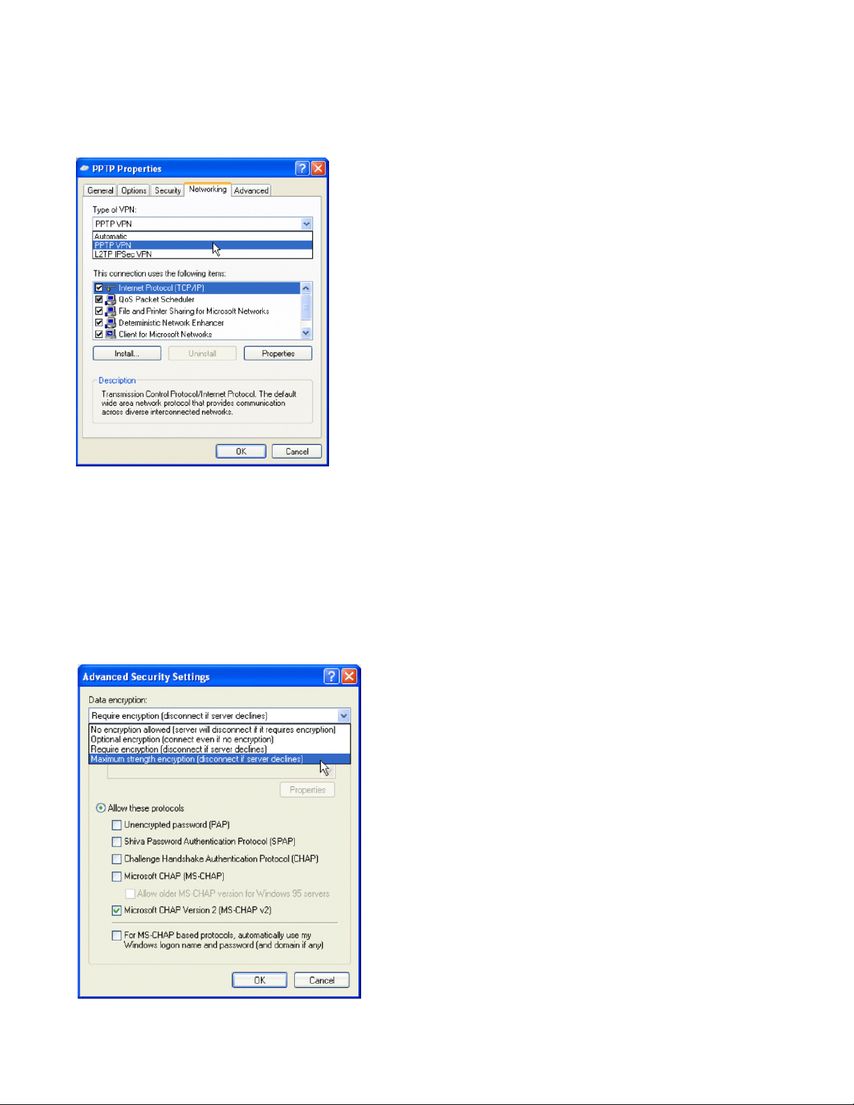
Figure 4-8. Connection Dialog Box—PPTP Properties
Step 10.
Step 11. Select PPTP VPN from the drop-down list for Type of VPN.
Click the Networking tab to specify the type of VPN.
Make sure that Internet Protocol (TCP/IP) is selected.
Step 12. Click the Security tab to customize the security protocols.
Step 13. Select Advanced (custom settings) on the Security tab and click Settings. The Advanced Security
Settings dialog box appears. See Figure 4-9.
Figure 4-9. Connection Dialog Box—Advanced Security Settings
4-10 ProCurve Secure Access 700wl Series Installation and Getting Started Guide
Page 55

Basic Configuration
Step 14.
Deselect the Microsoft CHAP (MS-CHAP) protocol option (this protocol is selected by default).
Leave Microsoft CHAP Version 2 selected. Only MS-CHAP v2 is set for use with the
Authenticated Access Policy.
Step 15. In the Data Encryption drop-down list, select Maximum strength encryption (disconnect if server
declines)
Step 16. Click OK to go back to the connection’s properties dialog box.
Step 17. Click OK to go back to the Properties dialog box.
Step 18. Click OK to close the Connect dialog box.
. This sets the length of the encryption key to 128 bits.
User Authentication Via PPTP Connection
Before starting the VPN connection, make sure your system has established a network connection with
the Access Control Server. You can use the
ipconfig /renew command to obtain an IP address from the Access Control Server.
Step 1. Open the PPTP connection you created in “PPTP Client Configuration” on page 4-8 by using the
shortcut on your desktop or open the connection from the Network Connections dialog box in
the Control Panel.
The Connect dialog box appears.
Step 2. Ty pe demo and password, or the user name and password you created in the built-in database, in
the
User name and Password text boxes, and click Connect to connect.
ipconfig command to verify the IP settings or use the
You may choose to save this user name and password for future use by checking the
Password
check box before clicking Connect.
Save
After the connection is successful, the connection icon appears in the system tray on the lower-right
corner of your screen as shown in Figure 4-10.
Figure 4-10. Connection Icon
External Authentication Service Configuration
If you use an external RADIUS authentication service and your user account already exists in the
RADIUS server’s database, you can configure the 700wl Series system to authenticate using the RADIUS
server rather than the built-in database.
Once you have successfully completed this configuration, you should be able to log on to the network
through the 700wl Series system using any legitimate user name and password recognized by your
RADIUS server.
ProCurve Secure Access 700wl Series Installation and Getting Started Guide 4-11
Page 56

Basic Configuration
Note: Your RADIUS server must be configured to recognize the Access Control Server as a RADIUS
client.
To configure the Rights Manager to use a RADIUS server for authentication, do the following:
Step 1. From your management station, point your browser to the IP address or hostname of your Access
Control Server, and logon to the Administrative Console.
The initial page of the Administrative Console appears.
Step 2. Click the RIGHTS button to go to the Rights Manager.
Step 3. Click Authentication Policies tab to go to the Authentication Policies page (Figure 4-11).
Figure 4-11. Authentication Policies Page
Step 4.
Click the Authentication Services link in the left panel.
The Authentication Services page appears.
Step 5. Click New.
The New Authentication Service—LDAP page appears.
Step 6. Click the RADIUS link to display the New Authentication Service—RADIUS page (Figure 4-12).
4-12 ProCurve Secure Access 700wl Series Installation and Getting Started Guide
Page 57

Figure 4-12. New RADIUS Authentication Service
Basic Configuration
Step 7.
Type the required information into the appropriate fields.
•Enter a
• Enter the
• Enter the
• Leave the
Name for this authentication service.
Server and Port information for your RADIUS server.
Secret that matches the RADIUS server secret, and enter it again in Confirm Secret.
Group Identity Field blank. This field is used to specify the name of a RADIUS
attribute that contains group information used to assign the authenticated user to an Identity
Profile.
If you elect to use this field, you must also create an Identity Profile to match the group
name that will be returned, and then add a row to the Rights Assignment Table to associate
an Access Policy with that Identity Profile.
• You can leave the default attribute name for the
Reauthentication Field. This field refers to the
name of a RADIUS attribute that specifies the duration (in seconds) after which the client is
forced to reauthenticate.
• Enter the authentication time-out period (in seconds) in
Step 8. Click Save. The Authentication Services page will reappear.
Step 9. Click the Authentication Policies link in the left panel. The Authentication Policies page will
Timeout, or leave the default.
appear.
ProCurve Secure Access 700wl Series Installation and Getting Started Guide 4-13
Page 58

Basic Configuration
Step 10.
Click System Authentication Policy in the Authentication Policies table to display the Edit
Authentication Policy page (Figure 4-13).
The newly added authentication service appears at the bottom of the list of available
Authentication Services for the System Authentication Policy.
Figure 4-13. Edit Authentication Policy Page
Step 11.
Use the row up/down buttons to move the newly added RADIUS service ahead of the Built-in
service, and put a check next to this service. (Leave the Built-in service checked as well.)
Step 12. Click Save.
The new RADIUS authentication service will now be the first service used to authenticate users
who are being authenticated by the System Authentication Policy. The System Authentication
Policy is used by the default Connection Profile “Any.”
Note: After you complete this step you will still be able to log in using the “demo” user name, because
the built-in database will still be searched if the user was not authenticated by the RADIUS server.
4-14 ProCurve Secure Access 700wl Series Installation and Getting Started Guide
Page 59
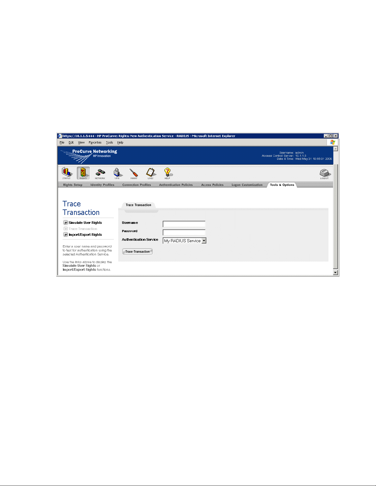
Basic Configuration
Verify the External Authentication Service
This procedure verifies that your RADIUS server will correctly authenticate users:
Step 1. Click the RIGHTS button to go to the Rights Manager.
Step 2. Click the To o ls & Option s tab, then click the Trace Transaction link in the left panel. The Trace
Transaction page appears, as shown in Figure 4-14.
Figure 4-14. Trace Transaction Page
Step 3.
Step 4. Make sure the RADIUS authentication service you created is selected in the Authentication
Enter a known user name and password into Username and Password.
Service drop-down list and click
Trace Transaction.
This function displays both the information sent to the Authentication Service and the returned
results. If something is incorrect, the Results Parameters will indicate an error. Possible reasons
for the error include:
• Invalid Username or Password or both
• RADIUS authentication service is not configured correctly
• RADIUS Server does not recognize the Access Control Server
If an error occurs, return to “External Authentication Service Configuration” on page 4-11 and
verify the RADIUS server configuration. Make sure to use a legitimate user name and password
recognized by the RADIUS server to test the RADIUS server.
If the RADIUS service works correctly, you should now be able to log the user off by going to URL
http://1.1.1.1 and log on again as a valid RADIUS user.
ProCurve Secure Access 700wl Series Installation and Getting Started Guide 4-15
Page 60

Page 61

TROUBLESHOOTING
This chapter presents troubleshooting procedures for the 700wl Series system. Table A-1 shows the
symptoms, probable cause and recommended action for a non-responsive unit.
Table A-1. Troubleshooting Guide
Symptom(s) Probable Cause Recommended Action
Power LED Off No Power Check power cord and AC outlet
Power LED on but fans
not running
Unit inaccessible from
customer network after
configuration
Unit inaccessible from
management system
after configuration
Defective Fan Replace Fan
Incorrect Cabling 1. Use straight-through Ethernet Cable
2. Ensure connectivity to network
Incorrect configuration Access system through network uplink,
check configuration. Check in particular
that IP address and hostname are
correct, and that hostname agrees with
IP address.
Incorrect network
configuration
1. Check default router
2. Check DNS server configuration
3. Check subnet mask
4. Check configuration of unit to use
DHCP or static ip address
A
Can’t get to Access
Control Server
Administrative Console
If all else fails 1. Reboot using command line
interface
2. Restart management system
3. Restore to factory defaults and start
over
Incorrect password 1. Check configuration, particularly
passwords
2. Reset to factory defaults
A-1
Page 62

Troubleshooting
Table A-1. Troubleshooting Guide (Continued)
Symptom(s) Probable Cause Recommended Action
No traffic through access
point
No initial web page Access Controller Module
No connection 1. Check cabling to access point.
Access point requires server
for WEP Key
Access Point requires
configuration
sees no web request
Browser problems Internet Explorer 5.01 with DLL
2. Use cross-over cable if required
3. Check power to Access Point
Create Identity Profile for MAC address
of access point that allows this traffic for
each access point.
If Access point uses static IP or wants
a dynamic IP address from network
DHCP server, make sure 700wl Series
system system is not doing NAT for
Access Point (create Identity Profile for
MAC address of Access Point that
allows Real IP Mode)
Use a browser to request http://1.1.1.1
schannel.dll version 4.86.1959.1877 is
known to have broken SSL
Certain downrev versions of MAC
OS/X browsers have broken SSL
A-2 ProCurve Secure Access 700wl Series Installation and Getting Started Guide
Page 63
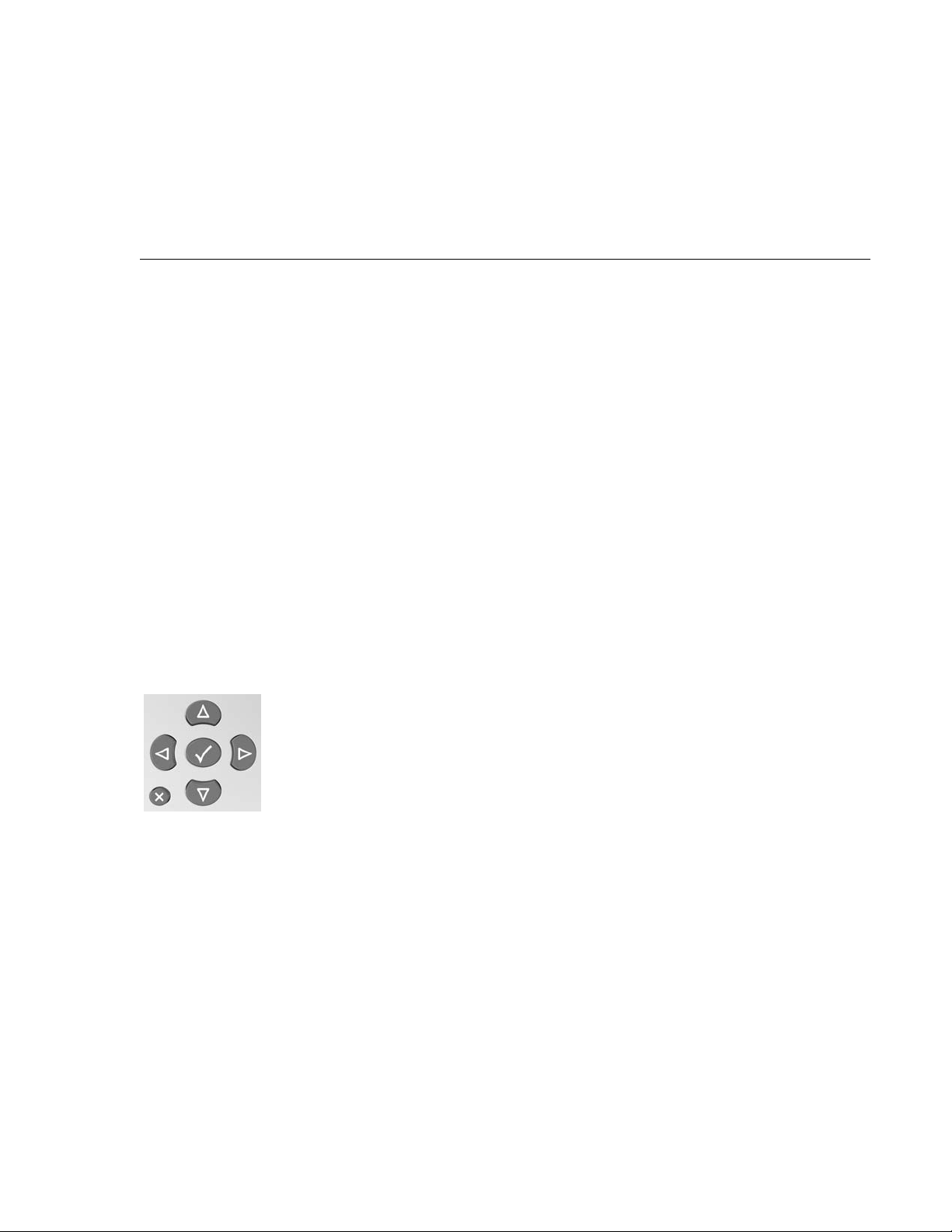
LCD DISPLAY DESCRIPTION
This appendix describes the LCD display on the Access Control Server. The display can be used to view
the system’s network parameters, and to power down the system. This appendix contains the following
sections:
Display Description . . . . . . . . . . . . . . . . . . . . . . . . . . . . . . . . . . . . . . . . . . . . . . . . . . . . . . . . . B-1
Powering On and System Boot . . . . . . . . . . . . . . . . . . . . . . . . . . . . . . . . . . . . . . . . . . . . . . . . B-2
Default Display . . . . . . . . . . . . . . . . . . . . . . . . . . . . . . . . . . . . . . . . . . . . . . . . . . . . . . . . . . . . . B-2
Main Menus . . . . . . . . . . . . . . . . . . . . . . . . . . . . . . . . . . . . . . . . . . . . . . . . . . . . . . . . . . . . . . . . B-2
System Shutdown . . . . . . . . . . . . . . . . . . . . . . . . . . . . . . . . . . . . . . . . . . . . . . . . . . . . . . . . . . . B-3
B
Display Description
The LCD display is located in the middle of the front panel of the Access Control Server. It is a 16character by two-line display, with six buttons located to the right of the display.
Figure B-1. LCD Controls
Button Functionality
Up and Down Arrows
These arrows allow the user to navigate between menus.
Left and Right Arrows
These arrows pressed together will initiate a SHUTDOWN. They are only available in the SHUTDOWN
submenu.
B-1
Page 64

Checkmark
The checkmark acts as a selection for a particular menu. When the checkmark is pressed, the display
goes into a submenu. Currently only SHUTDOWN has a submenu.
The X
This button cancels the current menu.
Powering On and System Boot
At power-on, the display remains blank until the system has initialized itself and displays Status:
Initializing.
The system then goes to the default display within a few seconds.
Default Display
Once the system has finished booting, the LCD will alternate between displaying the system type, for
example 700wl Series, the hardware number, for example 745wl and the uptime in days, hours and
minutes (ddd hh:mm) and the IP address.
Main Menus
When the default display is showing, repeatedly pressing the up or down arrow buttons will cycle
through the Main Menus of the display. The following lists the menus and what is displayed:
•IP: <IP ADDRESS>
•NETMASK: <NETMASK>
•MAC: <MAC ADDRESS>
•GATEWAY: <GATEWAY IP>
•DNS: <DNS IP ADDRESS>
•DATE & TIME: <CURRENT TIME and DATE>
• S/W VERSION: <CURRENT SOFTWARE VERSION>
• STATUS: <CURRENT STATUS>
Status can be one of the following:
— Rebooting. This status is when the system has been reset from the CLI.
— Running. Normal running state.
— Upgrading. During S/W upgrades.
— Initializing. When the LCD daemon starts for the first time after bootup.
— Error. When the LCD daemon fails to read the status file on disk.
— Invalid. When status is in an unrecognized state.
B-2 ProCurve Secure Access 700wl Series Installation and Getting Started Guide
Page 65

•SHUTDOWN?
Pressing the Checkmark button, the display becomes: ARE YOU SURE?
This command will reset the system when the proper key sequence is pushed (press left and right
buttons simultaneously).
System Shutdown
Pressing the up or down arrow button selects the SHUTDOWN? menu. This allows you to shut down
and power off the system. After pressing the checkmark button, ARE YOU SURE? displays.
If you are sure you want to shut down and power off the system, press left and right buttons
simultaneously. Otherwise, press the X button, and the display returns to the main display.
A system can take up to 30 seconds to perform the shutdown and power-off sequence.
ProCurve Secure Access 700wl Series Installation and Getting Started Guide B-3
Page 66

Page 67

TECHNICAL SPECIFICATIONS, SAFETY
AND COMPLIANCE
This appendix describes the technical specifications for the ProCurve 700wl Series. This appendix
includes the following sections:
Technical Specifications . . . . . . . . . . . . . . . . . . . . . . . . . . . . . . . . . . . . . . . . . . . . . . . . . . . . . . C-1
Safety and Regulatory Compliance . . . . . . . . . . . . . . . . . . . . . . . . . . . . . . . . . . . . . . . . . . . . C-2
Technical Specifications
Environmental Ranges
Operating Temperature Range 5 to +50°C
°
Storage Temperature Range -40 to +65
Humidity Range, non-condensing 5% to 90%
C
C
Operating Altitude Up to 10,000 ft. (3000 m)
Storage Altitude Up to 15,000 ft. (4570 m)
Power Requirements
AC Voltage 100-240 VAC
Power Supply Rating 6.3A max
Frequency Range 50/60 Hz
Heat Dissipation 580 BTU/Hr
Power Consumption (Nominal) 170W
Physical Dimensions
Weight 30 to 40 pounds (13.6 - 18.1 kg)
Height 3.5 in. (8.9 cm)
Width 17.0 inches (43.2 cm)
Depth 22 inches (55.9 cm)
C-1
Page 68

Safety and Regulatory Compliance
Safety Standards
UL 60950 - 1:2001
CAN/CSA 22.2 No. 60950
EMC Compliance
FCC Part 15 Class A
CE
EN 55022 (1998) Class A
EN 61000-3-2 (2000)
EN 61000-3-3 (1995)
Physical Interface
To the Access Control Server RJ45 10/100/1000 Base-T
Downlink Interfaces 2-port 10/100/1000 Copper
Ethernet card
2-port 1000 Base SX Fiber card
(LC connector)
1-port 1000 Base LX Fiber card
(LC Connector)
Management Console port DB-9, male
Encryption Acceleration Card
LEDs Power
Management Display 2-line LCD
C-2 ProCurve Secure Access 700wl Series Installation and Getting Started Guide
Page 69

CABLE AND CONNECTOR SPECIFICATIONS
This appendix describes the console port and the standard Ethernet cables to be used. This appendix
contains the following sections:
Serial Console Port . . . . . . . . . . . . . . . . . . . . . . . . . . . . . . . . . . . . . . . . . . . . . . . . . . . . . . . . . . D-1
10/100 Downlink Ethernet Cables . . . . . . . . . . . . . . . . . . . . . . . . . . . . . . . . . . . . . . . . . . . . . D-2
D
Serial Console Port
Table D-1 shows the pin assignments for the DB-9 serial console port, and Figure D-1 shows the pin
configuration. The console port is configured as an EIA/TIA-232 data terminal equipment (DTE) adapter.
If you are connecting a console device such as a laptop, you must use a serial crossover cable (null
modem cable).
Table D-1. Pin Assignments for Console Port
Pin Assignment Symbol
1 Data Carrier Detect DCD
2 Receive Data RXD
3 Transmit Data TXD
4 Data Terminal Ready DTR
5 Signal Ground GND
6 Data Set Ready DSR
7 Request to Send RTS
8 Clear to Send CTS
9 Ring Indicator RI
Figure D-1. Console Port Pin Configuration
D-1
Page 70

10/100 Downlink Ethernet Cables
Table D-2 shows the RJ-45 pin assignments for 10/100 Ethernet cables.
Table D-2. Pin Assignment for Ethernet Cables
Pin
Number
1 Incoming Data + (RD+)
2 Incoming Data - (RD-)
3 Outgoing Data + (TD+)
4 No Connection (NC)
5 No Connection (NC)
6 Outgoing Data - (TD-)
7 No Connection (NC)
Standard Ethernet
8 No Connection (NC)
Power Crossover Connector
Figure D-2 shows the schematic for a power crossover connector. In normal circumstances a crossover
connector should not be required. However, if for any reason you need to plug a +48VDC (IEEE 802.3af)
device into a -48VDC (Cisco-compatible) port, or vice versa, you will need to use a crossover connector.
Figure D-2. Pin assignment for a power crossover connector.
Pin Pin
1 RD+ 1 TD+
2 RD- 2 TD-
3 TD+ 3 RD+
4 +48VDC 4 -48VDC
5 +48VDC 5 -48VDC
6TD- 6 RD-
7 -48VDC 7 +48VDC
8 -48vdc 8 +48vdc
D-2 ProCurve Secure Access 700wl Series Installation and Getting Started Guide
Page 71
SAFETY AND EMC REGULATORY
E
STATEMENTS
Safety Information
Documentation reference symbol. If the product is marked with this symbol, refer to
the product documentation to get more information about the product.
WARNING A WARNING in the manual denotes a hazard that can cause injury or death.
CAUTION A CAUTION in the manual denotes a hazard that can damage equipment.
Do not proceed beyond a WARNING or CAUTION notice until you have understood
the hazardous conditions and have taken appropriate steps.
Grounding
These are safety class I products and have protective earthing terminals. There must be an uninterruptible
safety earth ground from the main power source to the product's input wiring terminals, power cord, or
supplied power cord set. Whenever it is likely that the protection has been impaired, disconnect the
power cord until the ground has been restored.
For LAN cable grounding:
• If your LAN covers an area served by more than one power distribution system, be sure their safety
grounds are securely interconnected.
• LAN cables may occasionally be subject to hazardous transient voltages (such as lightning or
disturbances in the electrical utilities power grid). Handle exposed metal components of the network
with caution.
Shielded Signal Cables
Use only shielded cables for connecting peripherals to any HP ProCurve 700wl Series device to reduce
the possibility of interference with radio communications services. Using shielded cables ensures that you
maintain the appropriate EMC classification for the intended environment.
Pluggable Equipment
For pluggable equipment, the socket outlet shall be installed near the equipment and shall be easily
accessible.
E-1
Page 72

Servicing
There are no user-serviceable parts inside these products. Any servicing, adjustment, maintenance, or
repair must be performed only by service-trained personnel.
Note for Service Personnel
Caution: There is a danger of a new battery exploding if it is incorrectly installed. Replace the battery
only with the same or equivalent type recommended by the manufacturer. Discard used batteries
according to the manufacturer’s instructions.
E-2 ProCurve Secure Access 700wl Series Installation and Getting Started Guide
Page 73

Informations concernant la sécurité
Symbole de référence à la documentation. Si le produit est marqué de ce
symbole, reportez-vous à la documentation du produit afin d'obtenir des
informations plus détaillées.
WARNING Dans la documentation, un WARNING indique un danger susceptible
d'entraîner des dommages corporels ou la mort.
CAUTION Un texte de mise en garde intitulé CAUTION indique un danger susceptible de
causer des dommages à l'équipement.
Ne continuez pas au-delà d'une rubrique WARNING ou CAUTION avant
d'avoir bien compris les conditions présentant un danger et pris les mesures
appropriées.
Cet appareil est un produit de classe I et possède une borne de mise à la terre. La source d'alimentation
principale doit être munie d'une prise de terre de sécurité installée aux bornes du câblage d'entrée, sur le
cordon d'alimentation ou le cordon de raccordement fourni avec le produit. Lorsque cette protection
semble avoir été endommagée, débrancher le cordon d'alimentation jusqu'à ce que la mise à la terre ait
été réparée.
Mise à la terre du câble de réseau local:
• si votre réseau local s'étend sur une zone desservie par plus d'un système de distribution de puissance,
assurez-vous que les prises de terre de sécurité soient convenablement interconnectées.
• Les câbles de réseaux locaux peuvent occasionnellement être soumis à des surtensions transitoires
dangereuses (telles que la foudre ou des perturbations dans le réseau d'alimentation public).
Manipulez les composants métalliques du réseau avec précautions.
Aucune pièce contenue à l'intérieur de ce produit ne peut être réparée par l'utilisateur. Tout dépannage,
réglage, entretien ou réparation devra être confié exclusivement à un personnel qualifié.
Attention: Ce produit contient une pile au Lithium remplacable. Risque d'explosion si la pile est
remplacee par un modele incorrect. Disposez des piles usagees selon les instructions.
ProCurve Secure Access 700wl Series Installation and Getting Started Guide E-3
Page 74

Hinweise zur Sicherheit
Symbol für Dokumentationsverweis. Wenn das Produkt mit diesem Symbol markiert
ist, schlagen Sie bitte in der Produktdokumentation nach, um mehr Informationen
über das Produkt zu erhalten.
WARNING Symbol für Dokumentationsverweis. Wenn das Produkt mit diesem Symbol markiert
ist, schlagen Sie bitte in der Produktdokumentation nach, um mehr Informationen
über das Produkt zu erhalten.
CAUTION Symbol für Dokumentationsverweis. Wenn das Produkt mit diesem Symbol markiert
ist, schlagen Sie bitte in der Produktdokumentation nach, um mehr Informationen
über das Produkt zu erhalten.
Fahren Sie nach dem Hinweis WARNING oder CAUTION erst fort, nachdem Sie den
Gefahrenzustand verstanden und die entsprechenden Maßnahmen ergriffen haben.
Dies ist ein Gerät der Sicherheitsklasse I und verfügt über einen schützenden Erdungsterminal. Der
Betrieb des Geräts erfordert eine ununterbrochene Sicherheitserdung von der Hauptstromquelle zu den
Geräteingabeterminals, den Netzkabeln oder dem mit Strom belieferten Netzkabelsatz voraus. Sobald
Grund zur Annahme besteht, daß der Schutz beeinträchtigt worden ist, das Netzkabel aus der
Wandsteckdose herausziehen, bis die Erdung wiederhergestellt ist.
Für LAN-Kabelerdung:
• Wenn Ihr LAN ein Gebiet umfaßt, das von mehr als einem Stromverteilungssystem beliefert wird,
müssen Sie sich vergewissern, daß die Sicherheitserdungen fest untereinander verbunden sind.
• LAN-Kabel können gelegentlich gefährlichen Übergangsspannungen ausgesetzt werden
(beispielsweise durch Blitz oder Störungen in dem Starkstromnetz des Elektrizitätswerks). Bei der
Handhabung exponierter Metallbestandteile des Netzwerkes Vorsicht walten lassen.
Dieses Gerät enthält innen keine durch den Benutzer zu wartenden Teile. Wartungs-, Anpassungs-,
Instandhaltungs- oder Reparaturarbeiten dürfen nur von geschultem Bedienungspersonal durchgeführt
werden.
Vorsicht: Dieses Produkt enhalt eine wechselbare Lithium Batterie. Es besteht Explosionsgefahr wenn
die Batterie durch einen falschen Typ ersetzt wird. Entsorgen Sie gebrauchte Batterien nach den
Anweisungen.
E-4 ProCurve Secure Access 700wl Series Installation and Getting Started Guide
Page 75

Considerazioni sulla sicurezza
Simbolo di riferimento alla documentazione. Se il prodotto è contrassegnato da
questo simbolo, fare riferimento alla documentazione sul prodotto per ulteriori
informazioni su di esso.
WARNING La dicitura WARNINGdenota un pericolo che può causare lesioni o morte.
CAUTION La dicituraCAUTION denota un pericolo che può danneggiare le attrezzature.
Non procedere oltre un avviso di WARNING o di CAUTIONprima di aver compreso
le condizioni di rischio e aver provveduto alle misure del caso.
Questo prodotto è omologato nella classe di sicurezza I ed ha un terminale protettivo di collegamento a
terra. Dev'essere installato un collegamento a terra di sicurezza, non interrompibile che vada dalla fonte
d'alimentazione principale ai terminali d'entrata, al cavo d'alimentazione oppure al set cavo
d'alimentazione fornito con il prodotto. Ogniqualvolta vi sia probabilità di danneggiamento della
protezione, disinserite il cavo d'alimentazione fino a quando il collegaento a terra non sia stato
ripristinato.
Per la messa a terra dei cavi LAN:
• se la vostra LAN copre un'area servita da più di un sistema di distribuzione elettrica, accertatevi che i
collegamenti a terra di sicurezza siano ben collegati fra loro;
• i cavi LAN possono occasionalmente andare soggetti a pericolose tensioni transitorie (ad esempio,
provocate da lampi o disturbi nella griglia d'alimentazione della società elettrica); siate cauti nel toccare
parti esposte in metallo della rete.
Nessun componente di questo prodotto può essere riparato dall'utente. Qualsiasi lavoro di riparazione,
messa a punto, manutenzione o assistenza va effettuato esclusivamente da personale specializzato.
Attenzione: questo prodotto contiene batterie ricaricabili al Litio. Se vengono utilizzate delle batterie
non adatte vi e' rischio di esplosione. Eliminare le batterie usate seguendo le istruzioni fornite a
riguardo.
ProCurve Secure Access 700wl Series Installation and Getting Started Guide E-5
Page 76

Consideraciones sobre seguridad
Símbolo de referencia a la documentación. Si el producto va marcado con este
símbolo, consultar la documentación del producto a fin de obtener mayor
información sobre el producto.
WARNING Una WARNING en la documentación señala un riesgo que podría resultar en
lesiones o la muerte.
CAUTION Una CAUTION en la documentación señala un riesgo que podría resultar en averías
al equipo.
No proseguir después de un símbolo de WARNING o CAUTION hasta no haber
entendido las condiciones peligrosas y haber tomado las medidas apropiadas.
Este aparato se enmarca dentro de la clase I de seguridad y se encuentra protegido por una borna de
puesta a tierra. Es preciso que exista una puesta a tierra continua desde la toma de alimentación eléctrica
hasta las bornas de los cables de entrada del aparato, el cable de alimentación o el juego de cable de
alimentación suministrado. Si existe la probabilidad de que la protección a tierra haya sufrido
desperfectos, desenchufar el cable de alimentación hasta haberse subsanado el problema.
Puesta a tierra del cable de la red local (LAN):
• Si la LAN abarca un área cuyo suministro eléctrico proviene de más de una red de distribución de
electricidad, cerciorarse de que las puestas a tierra estén conectadas entre sí de modo seguro.
• Es posible que los cables de la LAN se vean sometidos de vez en cuando a voltajes momentáneos que
entrañen peligro (rayos o alteraciones en la red de energía eléctrica). Manejar con precaución los
componentes de metal de la LAN que estén al descubierto.
Este aparato no contiene pieza alguna susceptible de reparación por parte del usuario. Todas las
reparaciones, ajustes o servicio de mantenimiento debe realizarlos solamente el técnico.
Curdado: Este producto contiente pilas remplasables de Lithium. Riesgo de exposion si la pila es
remplasada con el tipo incorrecto. Deseche la pilas usadas de accuerdo a las instrucciones.
E-6 ProCurve Secure Access 700wl Series Installation and Getting Started Guide
Page 77
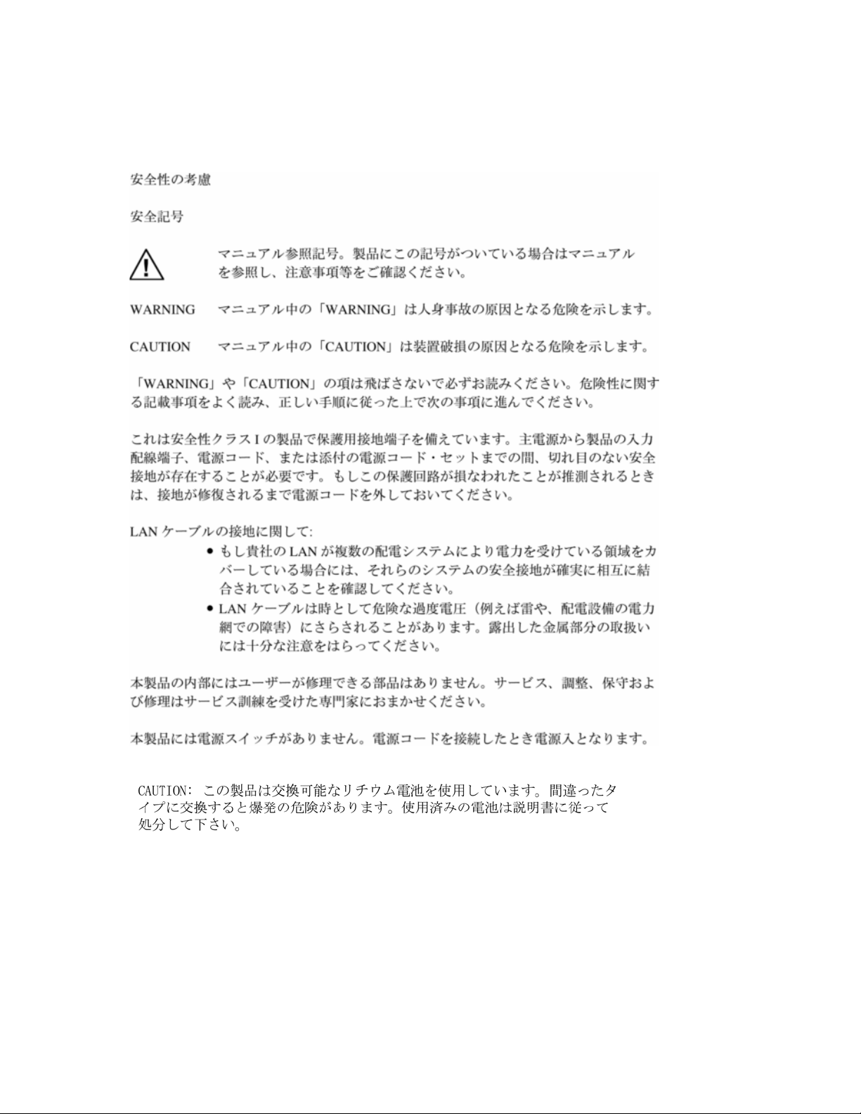
Safety Information (Japan)
ProCurve Secure Access 700wl Series Installation and Getting Started Guide E-7
Page 78

Safety Information (China)
E-8 ProCurve Secure Access 700wl Series Installation and Getting Started Guide
Page 79
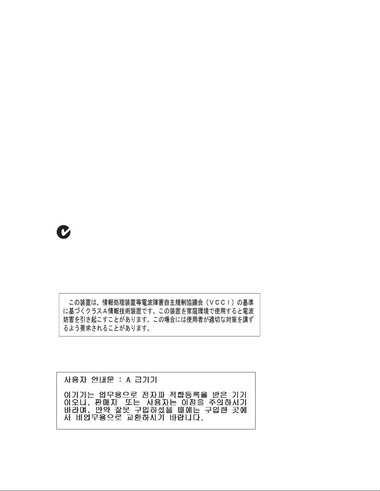
EMC Regulatory Statements
U.S.A.
FCC Class A
This equipment has been tested and found to comply with the limits for a Class A digital device,
pursuant to Part 15 of the FCC Rules. These limits are designed to provide reasonable protection against
interference when the equipment is operated in a commercial environment. This equipment generates,
uses, and can radiate radio frequency energy and, if not installed and used in accordance with the
instruction manual, may cause interference to radio communications. Operation of this equipment in a
residential area may cause interference in which case the user will be required to correct the interference
at his own expense.
Canada
This product complies with Class A Canadian EMC requirements.
Australia/New Zealand
This product complies with Australia/New Zealand EMC Class A requirements.
Japan
VCCI Class A
Korea
ProCurve Secure Access 700wl Series Installation and Getting Started Guide E-9
Page 80

BSMI
Regulatory Model Identification Number
For regulatory identification purposes, the ProCurve
Secure Access 700wl Series system components (Access
Controller 720wl, Access Control Server 740wl, 745wl,
Integrated Access Manager 760wl) are assigned a
Regulatory Model Number. The Regulatory Model
Number for these components areRSVLC-0206 and
RSVLC-0601.
This regulatory number should not be confused with the
marketing name or product numbers (J8153A, J8154A,
J8155A, J9038A)
E-10 ProCurve Secure Access 700wl Series Installation and Getting Started Guide
Page 81

European Community
ProCurve Secure Access 700wl Series Installation and Getting Started Guide E-11
Page 82

E-12 ProCurve Secure Access 700wl Series Installation and Getting Started Guide F-1
Page 83

RECYCLE STATEMENTS
F
Waste Electrical and Electronic Equipment (WEEE) Statements
Disposal of Waste Equipment by Users in Private Household in the European Union
This symbol on the product or on its packaging indicates that this product must not be disposed of with
your other household waste. Instead, it is your responsibility to dispose of your waste equipment by
handing it over to a designated collection point for the recycling of waste electrical and electronic
equipment. The separate collection and recycling of your waste equipment at the time of disposal will
help to conserve natural resources and ensure that it is recycled in a manner that protects human health
and the environment. For more information about where you can drop off your waste equipment for
recycling, please contact your local city office, your household waste disposal service or the shop where
you purchased the product.
Likvidace zařízení soukromými domácími uživateli v Evropské unii
Tento symbol na produktu nebo balení označuje výrobek, který nesmí být vyhozen spolu s ostatním
domácím odpadem. Povinností uživatele je předat takto označený odpad na předem určené sběrné
místo pro recyklaci elektrických a elektronických zařízení. Okamžité třídění a recyklace odpadu
pomůže uchovat přírodní prostředí a zajistí takový způsob recyklace, který ochrání zdraví a životní
prostředí člověka. Další informace o možnostech odevzdání odpadu k recyklaci získáte na
příslušném obecním nebo městském úřadě, od firmy zabývající se sběrem a svozem odpadu nebo v
obchodě, kde jste produkt zakoupili.
Bortskaffelse af affald fra husstande i den Europæiske Union
Hvis produktet eller dets emballage er forsynet med dette symbol, angiver det, at produktet ikke må
bortskaffes med andet almindeligt husholdningsaffald. I stedet er det dit ansvar at bortskaffe kasseret
udstyr ved at aflevere det på den kommunale genbrugsstation, der forestår genvinding af kasseret
elektrisk og elektronisk udstyr. Den centrale modtagelse og genvinding af kasseret udstyr i forbindelse
med bortskaffelsen bidrager til bevarelse af naturlige ressourcer og sikrer, at udstyret genvindes på en
måde, der beskytter både mennesker og miljø. Yderligere oplysninger om, hvor du kan aflevere kasseret
udstyr til genvinding, kan du få hos kommunen, den lokale genbrugsstation eller i den butik, hvor du
købte produktet.
Seadmete jäätmete kõrvaldamine eramajapidamistes Euroopa Liidus
See tootel või selle pakendil olev sümbol näitab, et kõnealust toodet ei tohi koos teiste majapidamisjäätmetega kõrvaldada. Teie kohus on oma seadmete jäätmed kõrvaldada, viies need elektri- ja elektroonikaseadmete jäätmete ringlussevõtmiseks selleks ettenähtud kogumispunkti. Seadmete jäätmete eraldi
kogumine ja ringlussevõtmine kõrvaldamise ajal aitab kaitsta loodusvarasid ning tagada, et ringlussevõtmine toimub viisil, mis kaitseb inimeste tervist ning keskkonda. Lisateabe saamiseks selle kohta, kuhu
oma seadmete jäätmed ringlussevõtmiseks viia, võtke palun ühendust oma kohaliku linnakantselei,
majapidamisjäätmete kõrvaldamise teenistuse või kauplusega, kust Te toote ostsite.
Laitteiden hävittäminen kotitalouksissa Euroopan unionin alueella
Jos tuotteessa tai sen pakkauksessa on tämä merkki, tuotetta ei saa hävittää kotitalousjätteiden mukana.
Tällöin hävitettävä laite on toimitettava sähkölaitteiden ja elektronisten laitteiden kierrätyspisteeseen.
Hävitettävien laitteiden erillinen käsittely ja kierrätys auttavat säästämään luonnonvaroja ja
varmistamaan, että laite kierrätetään tavalla, joka estää terveyshaitat ja suojelee luontoa. Lisätietoja
paikoista, joihin hävitettävät laitteet voi toimittaa kierrätettäväksi, saa ottamalla yhteyttä jätehuoltoon
tai liikkeeseen, josta tuote on ostettu.
Page 84

Έ
A
A
A
Élimination des appareils mis au rebut par les ménages dans l'Union européenne
Le symbole apposé sur ce produit ou sur son emballage indique que ce produit ne doit pas être jeté avec
les déchets ménagers ordinaires. Il est de votre responsabilité de mettre au rebut vos appareils en les
déposant dans les centres de collecte publique désignés pour le recyclage des équipements électriques
et électroniques. La collecte et le recyclage de vos appareils mis au rebut indépendamment du reste des
déchets contribue à la préservation des ressources naturelles et garantit que ces appareils seront recyclés
dans le respect de la santé humaine et de l'environnement. Pour obtenir plus d'informations sur les centres
de collecte et de recyclage des appareils mis au rebut, veuillez contacter les autorités locales de votre
région, les services de collecte des ordures ménagères ou le magasin dans lequel vous avez acheté ce
produit.
Entsorgung von Altgeräten aus privaten Haushalten in der EU
Das Symbol auf dem Produkt oder seiner Verpackung weist darauf hin, dass das Produkt nicht über den
normalen Hausmüll entsorgt werden darf. Benutzer sind verpflichtet, die Altgeräte an einer Rücknahmestelle für Elektro- und Elektronik-Altgeräte abzugeben. Die getrennte Sammlung und ordnungsgemäße Entsorgung Ihrer Altgeräte trägt zur Erhaltung der natürlichen Ressourcen bei und garantiert
eine Wiederverwertung, die die Gesundheit des Menschen und die Umwelt schützt. Informationen dazu,
wo Sie Rücknahmestellen für Ihre Altgeräte finden, erhalten Sie bei Ihrer Stadtverwaltung, den örtlichen
Müllentsorgungsbetrieben oder im Geschäft, in dem Sie das Gerät erworben haben
Απόρριψη άχρηστου εξοπλισµού από χρήστες σε ιδιωτικά νοικοκυριά στην Ευρωπαϊκή
νωση
Το σύµβολο αυτό στο προϊόν ή τη συσκευασία του υποδεικνύει ότι το συγκεκριµένο προϊόν δεν
πρέπει να διατίθεται µαζί µε τα άλλα οικιακά σας απορρίµµατα. Αντίθετα, είναι δική σας ευθύνη να
απορρίψετε τον άχρηστο εξοπλισµό σας παραδίδοντάς τον σε καθορισµένο σηµείο συλλογής για την
ανακύκλωση άχρηστου ηλεκτρικού και ηλεκτρονικού εξοπλισµού. Η ξεχωριστή συλλογή και
ανακύκλωση του άχρηστου εξοπλισµού σας κατά την απόρριψη θα συµβάλει στη διατήρηση των
φυσικών πόρων και θα διασφαλίσει ότι η ανακύκλωση γίνεται µε τρόπο που προστατεύει την
ανθρώπινη υγεία και το περιβάλλον. Για περισσότερες πληροφορίες σχετικά µε το πού µπορείτε να
παραδώσετε τον άχρηστο εξοπλισµό σας για ανακύκλωση, επικοινωνήστε µε το αρµόδιο τοπικό
γραφείο, την τοπική υπηρεσία διάθεσης οικιακών απορριµµάτων ή το κατάστηµα όπου αγοράσατε το
προϊόν.
Készülékek magánháztartásban történő selejtezése az Európai Unió területén
készüléken, illetve a készülék csomagolásán látható azonos szimbólum annak jelzésére szolgál,
hogy a készülék a selejtezés során az egyéb háztartási hulladéktól eltérő módon kezelendő. A
vásárló a hulladékká vált készüléket köteles a kijelölt gyűjtőhelyre szállítani az elektromos és
elektronikai készülékek újrahasznosítása céljából. A hulladékká vált készülékek selejtezéskori
begyűjtése és újrahasznosítása hozzájárul a természeti erőforrások megőrzéséhez, valamint
biztosítja a selejtezett termékek környezetre és emberi egészségre nézve biztonságos feldolgozását.
begyűjtés pontos helyéről bővebb tájékoztatást a lakhelye szerint illetékes önkormányzattól, az
illetékes szemételtakarító vállalattól, illetve a terméket elárusító helyen kaphat.
Smaltimento delle apparecchiature da parte di privati nel territorio dell'Unione Europea
Questo simbolo presente sul prodotto o sulla sua confezione indica che il prodotto non può essere smaltito
insieme ai rifiuti domestici. È responsabilità dell'utente smaltire le apparecchiature consegnandole presso
un punto di raccolta designato al riciclo e allo smaltimento di apparecchiature elettriche ed elettroniche.
La raccolta differenziata e il corretto riciclo delle apparecchiature da smaltire permette di proteggere la
salute degli individui e l'ecosistema. Per ulteriori informazioni relative ai punti di raccolta delle
apparecchiature, contattare l'ente locale per lo smaltimento dei rifiuti, oppure il negozio presso il quale
è stato acquistato il prodotto.
Nolietotu iekārtu iznīcināšanas noteikumi lietotājiem Eiropas Savienības privātajās
mājsaimniecībās
Šāds simbols uz izstrādājuma vai uz tā iesaiņojuma norāda, ka šo izstrādājumu nedrīkst izmest kopā ar
citiem sadzīves atkritumiem. Jūs atbildat par to, lai nolietotās iekārtas tiktu nodotas speciāli iekārtotos
punktos, kas paredzēti izmantoto elektrisko un elektronisko iekārtu savākšanai otrreizējai pārstrādei.
tsevišķa nolietoto iekārtu savākšana un otrreizējā pārstrāde palīdzēs saglabāt dabas resursus un
garantēs, ka šīs iekārtas tiks otrreizēji pārstrādātas tādā veidā, lai pasargātu vidi un cilvēku veselību.
Lai uzzinātu, kur nolietotās iekārtas var izmest otrreizējai pārstrādei, jāvēršas savas dzīves vietas
pašvaldībā, sadzīves atkritumu savākšanas dienestā vai veikalā, kurā izstrādājums tika nopirkts.
F-2 ProCurve Secure Access 700wl Series Installation and Getting Started Guide
Page 85

V
artotojų iš privačių namų ūkių įrangos atliekų šalinimas Europos Sąjungoje
Šis simbolis ant gaminio arba jo pakuotės rodo, kad šio gaminio šalinti kartu su kitomis namų ūkio
atliekomis negalima. Šalintinas įrangos atliekas privalote pristatyti į specialią surinkimo vietą elektros ir
elektroninės įrangos atliekoms perdirbti. Atskirai surenkamos ir perdirbamos šalintinos įrangos atliekos
padės saugoti gamtinius išteklius ir užtikrinti, kad jos bus perdirbtos tokiu būdu, kuris nekenkia žmonių
sveikatai ir aplinkai. Jeigu norite sužinoti daugiau apie tai, kur galima pristatyti perdirbtinas įrangos
atliekas, kreipkitės į savo seniūniją, namų ūkio atliekų šalinimo tarnybą arba parduotuvę, kurioje
įsigijote gaminį.
Verwijdering van afgedankte apparatuur door privé-gebruikers in de Europese Unie
Dit symbool op het product of de verpakking geeft aan dat dit product niet mag worden gedeponeerd bij
het normale huishoudelijke afval. U bent zelf verantwoordelijk voor het inleveren van uw afgedankte
apparatuur bij een inzamelingspunt voor het recyclen van oude elektrische en elektronische apparatuur.
Door uw oude apparatuur apart aan te bieden en te recyclen, kunnen natuurlijke bronnen worden
behouden en kan het materiaal worden hergebruikt op een manier waarmee de volksgezondheid en het
milieu worden beschermd. Neem contact op met uw gemeente, het afvalinzamelingsbedrijf of de winkel
waar u het product hebt gekocht voor meer informatie over inzamelingspunten waar u oude apparatuur
kunt aanbieden voor recycling.
Pozbywanie się zużytego sprzętu przez użytkowników w prywatnych gospodarstwach
domowych w Unii Europejskiej
Ten symbol na produkcie lub jego opakowaniu oznacza, że produktu nie wolno wyrzucać do zwykłych
pojemników na śmieci. Obowiązkiem użytkownika jest przekazanie zużytego sprzętu do
wyznaczonego punktu zbiórki w celu recyklingu odpadów powstałych ze sprzętu elektrycznego i
elektronicznego. Osobna zbiórka oraz recykling zużytego sprzętu pomogą w ochronie zasobów
naturalnych i zapewnią ponowne wprowadzenie go do obiegu w sposób chroniący zdrowie człowieka
i środowisko. Aby uzyskać więcej informacji o tym, gdzie można przekazać zużyty sprzęt do
recyklingu, należy się skontaktować z urzędem miasta, zakładem gospodarki odpadami lub sklepem,
w którym zakupiono produkt.
Descarte de Lixo Elétrico na Comunidade Européia
Este símbolo encontrado no produto ou na embalagem indica que o produto não deve ser descartado no
lixo doméstico comum. É responsabilidade do cliente descartar o material usado (lixo elétrico),
encaminhando-o para um ponto de coleta para reciclagem. A coleta e a reciclagem seletivas desse tipo
de lixo ajudarão a conservar as reservas naturais; sendo assim, a reciclagem será feita de uma forma
segura, protegendo o ambiente e a saúde das pessoas. Para obter mais informações sobre locais que
reciclam esse tipo de material, entre em contato com o escritório da HP em sua cidade, com o serviço
de coleta de lixo ou com a loja em que o produto foi adquirido.
Likvidácia vyradených zariadení v domácnostiach v Európskej únii
Symbol na výrobku alebo jeho balení označuje, že daný výrobok sa nesmie likvidovať s domovým
odpadom. Povinnosťou spotrebiteľa je odovzdať vyradené zariadenie v zbernom mieste, ktoré je
určené na recykláciu vyradených elektrických a elektronických zariadení. Separovaný zber a
recyklácia vyradených zariadení prispieva k ochrane prírodných zdrojov a zabezpečuje, že recyklácia
sa vykonáva spôsobom chrániacim ľudské zdravie a životné prostredie. Informácie o zberných
miestach na recykláciu vyradených zariadení vám poskytne miestne zastupiteľstvo, spoločnosť
zabezpečujúca odvoz domového odpadu alebo obchod, v ktorom ste si výrobok zakúpili.
Odstranjevanje odslužene opreme uporabnikov v zasebnih gospodinjstvih v Evropski uniji
Ta znak na izdelku ali njegovi embalaži pomeni, da izdelka ne smete odvreči med gospodinjske
odpadke. Nasprotno, odsluženo opremo morate predati na zbirališče, pooblaščeno za recikliranje
odslužene električne in elektronske opreme. Ločeno zbiranje in recikliranje odslužene opreme
prispeva k ohranjanju naravnih virov in zagotavlja recikliranje te opreme na zdravju in okolju neškodljiv
način. Za podrobnejše informacije o tem, kam lahko odpeljete odsluženo opremo na recikliranje, se
obrnite na pristojni organ, komunalno službo ali trgovino, kjer ste izdelek kupili.
ProCurve Secure Access 700wl Series Installation and Getting Started Guide F-3
Page 86

Eliminación de residuos de equipos eléctricos y electrónicos por parte de usuarios particulares en
la Unión Europea
Este símbolo en el producto o en su envase indica que no debe eliminarse junto con los desperdicios
generales de la casa. Es responsabilidad del usuario eliminar los residuos de este tipo depositándolos
en un "punto limpio" para el reciclado de residuos eléctricos y electrónicos. La recogida y el reciclado
selectivos de los residuos de aparatos eléctricos en el momento de su eliminación contribuirá a conservar
los recursos naturales y a garantizar el reciclado de estos residuos de forma que se proteja el medio
ambiente y la salud. Para obtener más información sobre los puntos de recogida de residuos eléctricos
y electrónicos para reciclado, póngase en contacto con su ayuntamiento, con el servicio de eliminación
de residuos domésticos o con el establecimiento en el que adquirió el producto.
Bortskaffande av avfallsprodukter från användare i privathushåll inom Europeiska Unionen
Om den här symbolen visas på produkten eller förpackningen betyder det att produkten inte får
slängas på samma ställe som hushållssopor. I stället är det ditt ansvar att bortskaffa avfallet genom att
överlämna det till ett uppsamlingsställe avsett för återvinning av avfall från elektriska och elektroniska
produkter. Separat insamling och återvinning av avfallet hjälper till att spara på våra naturresurser och
gör att avfallet återvinns på ett sätt som skyddar människors hälsa och miljön. Kontakta ditt lokala
kommunkontor, din närmsta återvinningsstation för hushållsavfall eller affären där du köpte produkten
för att få mer information om var du kan lämna ditt avfall för återvinning.
F-4 ProCurve Secure Access 700wl Series Installation and Getting Started Guide
Page 87

INDEX
Numerics
1/0 button 2-3
10/100/1000 ports 2-3
10/100BaseTx 3-18
A
Access Control Server
accessing via browser
connecting a serial console 3-3
connecting to network 3-5
default router 3-3
DNS server addresses 3-3, 3-15
domain name 3-3
front panel illustrated 2-2
gateway address 3-3
hostname 3-3
information required for network installation
3-3, 3-14
IP address 3-15
IP address considerations 3-2
network installation procedure 3-4
obtaining IP address via DHCP 3-2
order of installation 1-2, 3-1
shared secret 3-3, 3-12, 3-15
static IP address, using 3-2, 3-14
subnet range 3-3
system ID (MAC address) 3-4
Access Controller A-2
default router 3-15
gateway address 3-15
IP address considerations 3-14
subnet range 3-15
Access Point A-2
administrator interface
login to
administrator login
changing via browser interface
changing via CLI 3-5, 3-7
default name and password 3-9
to browser interface 3-9
air flow 2-7
air space 2-7
audience 3-vii
3-6, 3-8
3-9
3-12
B
boot prompt, serial console 3-4
booting
system booting message, LCD
browser interface
accessing Access Control Server using
accessing Control Server using 3-7
network installation using 3-8
browser-interface
login to
B-2
3-6, 3-8
3-9
C
cables
null modem
serial crossover 2-6
shielded signal cable advisory E-1
caution
air space and flow
chassis grounding 2-7
operating temperature 2-7
power cord 2-7
changing administrator login/password
via browser interface
via CLI 3-5, 3-7
chassis
dimensions
front panel, illustrated 2-2
front power button 2-3
grounding 2-7
mounting 2-6
rack-mounting 2-6 to 2-7
rear power switch 2-4
weight 2-2
Command Line
for network installation, Access Control Server
3-3, 3-15
Command Line Interface (CLI)
for network installation
connecting
power
power cord 2-7
connectors
DB9
Network Uplink 2-1
2-6
2-7
3-12
2-2
3-14
2-7
2-3, 3-3
IX-1
Page 88

reserved 2-1
RJ45 2-1, 2-3
Control Server
accessing via browser
3-7
network installation procedure 3-6
system ID (MAC address) 3-7
D
DB9 connector 2-3, 3-3
default router
Access Control Server
Access Controller 3-15
setting via CLI 3-5
DHCP
Access Control Server address
and Access Control Server network installation
3-8
obtaining IP address using 3-2
setting on/off in browser interface 3-11
display, LCD 2-3, B-1 to B-3
DNS server
addresses for, Access Control Server
setting address via CLI 3-5
setting addresses via browser interface 3-11
document conventions 3-ix
document organization 3-vii
documentation
CD-ROM
related publications 3-ix
documentation kit 2-6
domain name
Access Control Server
setting via browser interface 3-11
Dynamic Host Configuration Protocol, see DHCP
3-3
3-8
3-3, 3-15
2-6
3-3
Access Control Server
3-3
setting via browser interface 3-11
setting via CLI 3-5
humidity 2-6, C-1
I
I/O ports. See downlink ports
Identity Profile
A-2
Incorrect configuration A-1
Incorrect network configuration A-1
Incorrect password A-1
input voltage 2-2
installation, hardware
package contents
2-6
unpacking 2-6
installation, network. See network installation
Integrated Access Manager
hard disk drive
2-2
IP address
and LCD display
3-8
considerations 3-2, 3-14
DHCP-provided 3-8
for Access Control Server 3-3
for Access Manager 3-15
obtaining via DHCP 3-2
of Access Control Server 3-15
setting via CLI 3-5
IP address, Access Control Server
using static IP address
3-2, 3-14
K
kit
documentation
hardware and accessories 2-6
2-6
E
EMC regulatory statements E-9
L
LCD 2-3, B-1 to B-3
are you sure? display B-3
F
front panel
LCD display
B-1 to B-3
default display B-2
system booting message B-2
system powering down message B-3
LED
G
gateway
Access Control Server
3-3
Access Controller 3-15
setting via CLI 3-5
grounding, chassis 2-7
H
power
LEDs
Network Uplink status
power status 2-3
system status 2-3
login
to administrator interface
to serial console 3-4
A-1
2-4
3-9
hard disk drive 2-2
hardware and accessories kit 2-6
heat dissipation 2-6, C-1
hostname
IX-2 ProCurve Secure Access 700wl Series Installation and Getting Started Guide
M
MAC address
Access Control Server system ID
3-4
Page 89

Control Server system ID 3-7
mounting the chassis 2-6
N
netmask
setting in browser interface
3-11
network installation
and DHCP
3-8
order of 1-2, 3-1
procedure using CLI 3-4, 3-6
procedure, Control Server 3-1
required information 1-3, 3-3, 3-14
using CLI 3-14
using CLI, Access Control Server 3-3, 3-15
via browser interface 3-8
network interface, see network uplink
Network Uplink
2-1
status LEDs 2-4
network uplink
illustrated
2-4
Network Uplink port 2-3
connecting to network 3-5, 3-8
No connection A-2
O
operating temperature caution 2-7
output voltage 2-2
P
package contents 2-6
password
changing via browser interface
changing via CLI 3-5, 3-7
pin assignments D-1
pin configuration D-1
pluggable equipment advisory E-1
ports
10/100/1000BASET
description 2-3
Network Uplink 2-1, 2-3
Reserved 2-1
serial console 2-3
serial console on Control Server 3-3
uplink port on Control Server 3-6
power
connecting
front panel button 2-3
input (AC) 2-6
input current (AC) 2-6
LED indicator A-1
rear chassis switch 2-3, 2-4
site requirements 2-5
specifications 2-5
status LED 2-3
power button 2-3
3-12
2-3
2-7
power cord
connecting
2-7
power cord caution 2-7
power switch 2-3, 2-4
powering a system on/off 2-3
R
rack-mounting 2-6 to 2-7
regulatory statements E-9
related publications 3-ix
Reserved port 2-1
RJ45 connector 2-1, 2-3
pinouts D-2
S
safety and regulatory statements E-1
serial cable 3-4
serial console
boot prompt
3-4
connecting to a Access Control Server 3-3
issuing commands from 3-4
logging on 3-4
serial console port, see serial port
serial port
2-3, 3-3
shared secret
on Access Control Server
3-3, 3-15
setting via browser interface 3-12
setting via CLI 3-5, 3-7
shielded signal cable advisory E-1
site planning 2-4
specifications
air space
2-7
humidity 2-6, C-1
power 2-5
temperature 2-6, C-1
SSH 3-6
issuing commands from 3-6
static IP address
for Access Control Server
3-2, 3-14
subnet mask
setting in browser interface
3-11
subnet range
for Access Control Server
3-3
for Access Controller 3-15
system status indicators 2-3
T
temperature 2-6, C-1
U
Unit inaccessible A-1
unpacking 2-6
uplink port 3-6
ProCurve Secure Access 700wl Series Installation and Getting Started Guide IX-3
Page 90

V
voltage
input
output 2-2
2-2
W
warranty 1-ii
web interface, see browser interface
WEP Key
A-2
IX-4 ProCurve Secure Access 700wl Series Installation and Getting Started Guide
Page 91

Page 92

Technical information in this document
is subject to change without notice.
© Copyright 2004, 2006 Hewlett-Packard
Development Company, L.P. Reproduction,
adaptation, or translation without prior
written permission is prohibited except as
allowed under the copyright laws.
Printed in the US
June 2006
Manual Part Number
5991-4756
*5991-4756*
 Loading...